goce - earth online - esaearth.esa.int/workshops/goce06/participants/337/pres_popescu_337.pdf ·...
TRANSCRIPT

EOEP Science Review Meeting 14 and 15 June 2005
GOCE
Gravity field
and steady-state
Ocean Circulation Explorer
Alex Popescu ESA/ESTEC
www.esa.int/livingplanet/goce
Satellite Design and Status

GOCE Mission Objectives
- Determine the Earth’s gravity field with an accuracy of 1 mgal
(I.e. 1 millionth of the Earth Gravity) via the measurement of
the diagonal components of the gravity gradient tensor
- Determine the geoid (I.e. the equipotential surface for a
hypothetical ocean at rest ) with a radial accuracy of 1 to2 cm
- Achieve this at length scales down to 100 km

GOCE: Main Payload Characteristics
- The Gradiometer (EGG): Measuring the diagonal components of
the gravity gradient tensor with an accuracy of 6 mE/sqrt(Hz)
within a bandwidth of 5 mHz to 100 mHz, i.e. consistent with
degree and order 10 to 200
- The High-to-Low Satellite to Satellite Tracking Receiver (SSTI):
Orbit reconstitution with an accuracy of 1-2 cm

GOCE payload and satellite
• Electrostatic GravityGradiometer
• 6 tri-axial electrostaticaccelerometers for themeasurement of thegravity gradient tensor
• Satellite-to-Satellite-Tracking Instrument(SSTI)
• 3 Star trackers
• GPS antenna & 12-channel L1/L2 receiverfor precise orbitdetermination
• Laser Retroreflector

GOCE Satellite: Main Requirements
Orbit: Circular and as low as possible but still compatible
with capability to:
• compensate the drag
• not loose the satellite in case of an on-board anomaly
Injection altitude = 275 km, geodetic measurement altitude =
250/260 km
Other orbit characteristics: * 96.5deg inclination for near global
coverage
* Dawn-dusk sun-synchronous orbit to allow for maximum solar
power
Total measurement time:
2 times 6 months with additional 6 months possible extension
Design requirement: No moving parts and ultra-high thermo-elastic
stability

GOCE Satellite: Main Design Divers
• Spacecraft Cross Section minimized in the flight direction
• Accommodation of Gradiometer Instrument (close to C.o.M)
• High thermo-elastic stability
• Provisions to minimize Micro-disturbance Effects
• High level of Autonomy (up to 72 hours)
• Autonomous Survival Capability up to 8 days

… feeling for the numbers
0.2 gram
~2E-03 N
1 000 000 tonne
Downforce
Super-tanker acceleration:
29
3
s
m 102
kg 101
N 102 12!!
"#"
"

GOCE Spacecraft


Gradiometer configuration and data processing
ZJ2000
YJ2000
XJ2000
!
i
u
XO
YO
ZO
OO
XGR
ZGR
YGR
A1
A4
A2
A5
A3
A6
Linear accelerations measured by the six
accelerometers of the Electrostatic Gravity
Gradiometer: a'1,X, a'1,Y , a'1,Z , ……., a'6,X, a'6,Y , a'6,Z
Application of Gradiometer Calibration
Matrices: M14, M25, M36, containing the
accelerometer scale factors, sensitive axes
alignments (during on-orbit calibration only)
Measured accelerations corrected by means of the
Calibration Matrices ! actual accelerations experienced
by the proof masses: a1,X, a1,Y , a1,Z , ……., a6,X, a6,Y , a6,Z
Reconstruction of centrifugal accelerations measured bythe Gradiometer & star tracker along 3 axes: "X
2, "Y2, "
Z2
Reconstruction of the Gravity Gradient
Tensor components (Level 1b product):
,…….2
Z
2
Y
X
X,14,
XXˆˆ
ˆ
ˆ2U !! """=L
ad

The 6 accelerometers are situated around the
center of mass of the satellite
Electrostatic Gravity Gradiometer

3 pairs of GOCE Accelerometers
q Pt-Rh proof mass of 4x4x1 cm and 320 gmass
q Accelerometer cage made of ULE ceramicswith gold electrodes for 6 DOF control
q Sole plate in INVAR
q 8 electrode pairs per sensitive element (forredundancy reasons)
q Proof mass grounded by a 25 mm long and5 micron “thick” gold wire

Accelerometer Sensor Head: Assembled

ASH FM 1

Carbon-Carbon Arm Structurewith Accelerometer Pair, includingmagnetic shielding and connectors
OAGY: Y-direction
One-Axis Gradiometer

Gradiometer Structural Model

Gradiometer Electrical Sub-System FM

SSTI configuration and data processing
Science Data Processing
L1, L2 carrier phases and
pseudo-range (code) measured
by the GPS receiver for up to
12 GPS satellites, and receiver
temperatures
Determination of the inter-
frequency bias calibration
parameter from the receiver
temperatures
L1, L2 carrier phase measurements corrected by means of the
estimated inter-frequency bias, satellite positions and reconstructed
orbit (Level 1b product)
Satellite position determination
from the pseudo-range
measurements and orbit
reconstruction
GPS


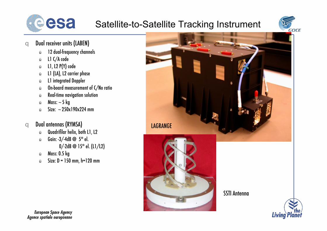
Satellite-to-Satellite Tracking Instrument
q Dual receiver units (LABEN)
ü 12 dual-frequency channels
ü L1 C/A code
ü L1, L2 P(Y) code
ü L1 (LA), L2 carrier phase
ü L1 integrated Doppler
ü On-board measurement of C/No ratio
ü Real-time navigation solution
ü Mass: ~ 5 kg
ü Size: ~ 250x190x224!mm
q Dual antennas (RYMSA)ü Quadrifilar helix, both L1, L2
ü Gain: -3/-4dB @ 5° el.
0/-2dB @ 15° el. (L1/L2)
ü Mass: 0.5 kg
ü Size: D = 150 mm, h=120 mm
LAGRANGE
SSTI Antenna


Star Trackers: Attitude Knowledge
TECHNICAL CHARACTERISTICS
Power DPU + CHU 6.9 W
CHU mass 300 g
DPU mass 835 g
Baffle mass 330 g
CHU dimension 50x50x57mm
DPU dimension 102x100x100mm
Baffle dimension 76x76x130mm
Input voltage 6.8V to 75V
Data I/F RS422
Processor board 486DX4/100
PERFORMANCE REQUIREMENTS
Precision (1 !) Cross-axis BoresightBias 1.03 arcsec 1.03 arcsecBias Stability 0.62 arcsec 0.62 arcsecShort Term 3 arcsec 10 arcsecNEA 2 arcsec 20 arcsec
Output data rate 2 Hz
Data latency ~900 ms
Slew rate 2 o/s
Exclusion angles 30o Sun; 20o Earth
Flight heritage:
CHAMP, GRACE 1 & 2,
ADEOS-2, PROBA

Laser Retroreflector

Ion Propulsion
Key PerformanceRequirements– Thrust Range 1.5 - 20 mN,
commanded
@ 10 Hz
– Thrust Error: # ±8%
– Thrust Vector Stability: < 0.2°half cone
Implementation Features
– ITA: Qinetiq´s T5 Mk-5
• dished grid system
• hollow cathodes
• magnetic field system
– IPCU:
• 11 ITA power supplies (2
regulated)
• PXFA drive & read-out
interfaces
• processor controlled thrust
regulation,
incl. special FDIR
– PXFA:
• linearly controlled Xe main
flow
• branch isolation by latch
valves
– XST:
• 40 kg Xenon storage
capability

Ion Motor Testing
