…going one step further - 3b scientific · el modelo de 2 piezas representa de manera...
TRANSCRIPT

(1000312)
K24
…go i ng one s t ep f u r t he r

2

®
Latin
1 Venacentralis 2 Lobulusportalis 3 Canalisportalis 4 Acinushepatis 5 Zona1 6 Zona2 7 Zona3 8 Lobulushepatis 9 Ductusinterlobularisbilifer10 Arteriainterlobularis11 Venainterlobularis12 CellofKupffer13 Hepaticocytus14 Terminalbileduct(Herring’scanal)15 Vasasinusoidea16 Canaliculibiliferi
3

®
English
4
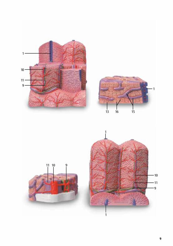
This2-partmodelshowsahighlymagnifieddiagrammaticviewofasectionoftheliver.Itillustratesthestructureofthefunctionalandstructuralcomponentsoftheliverintwodifferentenlargements.Theleftpartofthemodelshowsasectionoftheliverthatcomprisesseveralliverlobules.Theimportantmorpho-logicalandfunctionalregionsaredepictedonvariouslevels:Thecentralveinisatthecenteroftheclassicliverlobule.Locatedatthecenteroftheportalliverlobuleistheportalcanalwiththeinterlobulararteryandveinandaninterlobularbileduct(hepatictriad,Glisson’striad).Theliveracinusconsistsofthreezonesanditsaxisisdefinedbyonesidebrancheachoftheinterlobulararteryandoftheinterlobularvein.Therightpartofthemodelisahighlymagnifiedviewofthesectionedliverlobuleontheleft.
3B MICROanatomy™ Liver
1 Centralvein 2 Portalliverlobule 3 Portalcanal 4 Liveracinus 5 Zone1 6 Zone2 7 Zone3 8 Classicliverlobule 9 Interlobularbileduct10 Interlobularartery11 Interlobularvein12 CellofKupffer13 Hepatocyte14 Terminalbileduct(Herring’scanal)15 Liversinusoids16 Bilecanaliculi

®
Deutsch
5
3B MICROanatomy™ LeberDas2-teiligeModellzeigteinenschematischdargestelltenAusschnittderLeberinstarkerVergrößerung.EsdientderVeranschaulichungdesAufbausderFunktions-undBaueinheitenderLeberinzweiunter-schiedlichenVergrößerungen.DerlinkeModellteilstellteinenLeberausschnittdar,dermehrereLeberläppchenumfasst.Diemorpho-logischundfunktionellwichtigenRegionenwurdeninverschiedenenAbstufungenherausgearbeitet:DieZentralveneistdasZentrumdesZentralvenen-Leberläppchens(klassischesLeberläppchen).ImMittelpunktdesPortalvenenläppchensstehtdasperiportaleFeldmitderA.undV.interlobularissowieeineminter-lobulärenGallengang(Triashepatica,Glisson-Trias).DerLeberazinusbestehtausdreiZonen,wobeiseineAchsedurchjeeinenSeitenzweigderA.undV.interlobularisgebildetwird.DerrechteModellteilistdiestarkeVergrößerungdesangeschnittenenLeberläppchenslinks.
1 Zentralvene 2 Portalvenenläppchen 3 PeriportalesFeld 4 Leberazinus 5 Zone1 6 Zone2 7 Zone3 8 Zentralvenen-Leberläppchen 9 InterlobulärerGallengang10 Arteriainterlobularis11 Venainterlobularis12 Kupffer-Zelle13 Leberzelle14 Herring-Kanal15 Lebersinusoide16 Gallenkanälchen

®
6
Elmodelode2piezasrepresentademaneraesquemáticayagranaumentounsectordelhígado.Sirveparavisualizarlaestructuradelasunidadesfuncionalesyconstructivasdelhígadocondosdiferentesmagnificaciones.Laparteizquierdadelmodelorepresentaunsectordelhígadoqueincluyevarioslobulilloshepáticos.Lasregionesdeimportanciamorfológicayfuncionalsehanpuestoderelievecondiferentesniveles:lavenacentralconstituyeelcentrodellobulilloclásico.Enelcentrodellobulilloportalseencuentraelespa-cioperiportalconlaarteriayvenainterlobularesasícomounconductobiliarinterlobular(tríadahepática,triángulodeGlisson).Elácinohepáticoconstadetreszonas,estandosuejeformadoporunaramalateraldelaarteriayvenainterlobulares,respectivamente.Lapartederechadelmodelorepresentaagranaumentouncorteincisivodellobulillohepáticoalaizquierda.
1 Venacentral 2 Lobulilloportal 3 Espacioperiportal 4 Ácinohepático 5 Zona1 6 Zona2 7 Zona3 8 Lobulilloclásico 9 Conductobiliarinterlobular10 Arteriainterlobular11 Venainterlobular12 CéluladeKupffer13 Hepatocito14 CanaldeHering15 Sinusoideshepáticos16 Canalículobiliar
Lengua 3B MICROanatomy™ Español
®
7
Français Foie 3B MICROanatomy™Lemodèleen2partiesmontreunecoupedufoiefortementagrandie.Ellepermetl’examendelastructuredesunitésfonctionnellesetstructurellesdufoiesousdeuxagrandissementsdifférents.Lapartiegauchedumodèlereprésenteunecoupedufoiecomprenantplusieurslobules.Lesrégionsimportantesauplanmorphologiqueetfonctionnelontétéélaboréesendégradés:laveinecentraleestlecentredelaveinecentraledulobulehépatique(lobulehépatiqueclassique).Lechamppériportalavecl’artèreetlaveineinterlobulairesainsiqu’uncanalcholédoque(triadehépatique,triadedeGlisson)setrouventaucentredelaveineportedulobule.L’acinushépatiquesecomposedetroiszones;sonaxeestforméparunebranchelatéraledel’artèreetdelaveineinterlobulaires.Lapartiedroitedumodèleestunfortagrandissementdulobulehépatiquesectionnéàgauche.
1 Veinecentrale 2 Veineporteinterlobulaire 3 Champpériportal 4 Acinushépatique 5 Zone1 6 Zone2 7 Zone3 8 Veinecentraleinterlobulaire 9 Canalcholédoqueinterlobulaire10 Artèreinterlobulaire11 Veineinterlobulaire12 CelluledeKupffer13 Cellulehépatique14 CanaldeHerring15 Sinusoïdehépatique16 Caniculesbiliaires

8
8
1
6
4
3
2
1
7
5
1211109
13
15
16
1
14
10
11
9
9
911
10
1
10
11
9
1
151613
1
1
91011

®
10
PortuguêsFígado 3B MICROanatomy™Questomodelloinduepartimostraunasezioneschematicaefortementeingranditadelfegato.Ilmodelloillustralacomposizionedelleunitàstrutturaliefunzionalidelfegatoconduediversiingrandimenti.Lapartesinistradelmodellorappresentaunasezionedelfegatocomprendentediversilobuliepatici.Leregioniimportantidalpuntodivistamorfologicoefunzionalesonostateevidenziateindiversegradazi-oni:lavenacentraleèilnucleodellobuloepatico(lobuloepaticoclassico).Alcentrodellobulodellavenaportalec’èlospaziointerlobulareoportaleconl’a.elav.interlobularieundottointerlobulare(triadeepatica,triadediGlisson).L’acinoepaticoècompostoda3zoneeilsuoasseèformatodaramificazionilateralidell’a.edellav.interlobulari.Lapartedestradelmodelloèunforteingrandimentodellobuloepaticosinistroinsezione.
1 Veiacentral 2 Lóbuloportal 3 Áreaperiportal 4 Ácinohepático 5 Zona1 6 Zona2 7 Zona3 8 Lóbulohepáticodaveiacentral 9 Ductobiliarinterlobular10 Artériainterlobular11 Veiainterlobular12 CéluladeKupffer13 Hepatócito14 Canalbiliarterminal15 Senóidehepática16 Canaisbiliares

®
English
11
Italiano Fegato MICROanatomy™ 3B Questomodelloinduepartimostraunasezioneschematicaefortementeingranditadelfegato.Ilmodelloillustralacomposizionedelleunitàstrutturaliefunzionalidelfegatoconduediversiingrandimenti.Lapartesinistradelmodellorappresentaunasezionedelfegatocomprendentediversilobuliepatici.Leregioniimportantidalpuntodivistamorfologicoefunzionalesonostateevidenziateindiversegradazi-oni:lavenacentraleèilnucleodellobuloepatico(lobuloepaticoclassico).Alcentrodellobulodellavenaportalec’èlospaziointerlobulareoportaleconl’a.elav.interlobularieundottointerlobulare(triadeepatica,triadediGlisson).L’acinoepaticoècompostoda3zoneeilsuoasseèformatodaramificazionilateralidell’a.edellav.interlobulari.Lapartedestradelmodelloèunforteingrandimentodellobuloepaticosinistroinsezione.
1 Venacentrale 2 Lobuloportale 3 Spaziointerlobulareoportale 4 Acinoepatico 5 Zona1 6 Zona2 7 Zona3 8 Lobuloepatico 9 Dottointerlobulare10 Arteriainterlobulare11 Venainterlobulare12 CelluledeKupffer13 Cellulehépatique14 CanaldeHerring15 Sinusoïdehépatique16 Caniculesbiliaires

12

®
DeutschРусский 3B MICROanatomy™ печени Эта модель, состоящая из 2 частей, в сильном увеличении демонстрирует схематическое строение печени в разрезе. Она иллюстрирует строение функционально-структурных единиц печени в двух различных увеличениях. Левая часть модели показывает разрез печени, на котором видны несколько печеночных долек. Важные морфологические и функциональные участки представлены на различных уровнях: центральная вена расположена в центре классической печеночной дольки. В центре портальной печеночной дольки расположен портальный канал с междольковой артерией и веной и междольковый желчный проток (печеночная триада, триада Глиссона). Печеночный ацинус состоит из трех зон, и его ось формируется одной боковой ветвью междольковой артерии и междольковой вены соответственно. Правая часть модели представляет собой многократно увеличенную печеночную дольку (показанную слева) в разрезе.
1 Центральная вена 2 Портальная печеночная долька 3 Портальный канал 4 Печеночный ацинус 5 Зона 1 6 Зона 2 7 Зона 3 8 Классическая печеночная долька 9 Междольковый желчный проток 10 Междольковая артерия 11 Междольковая вена 12 Клетка Купфера 13 Гепатоцит 14 Терминальный желчный проток (канал Геринга) 15 Печеночные синусоиды 16 Желчные канальцы
13

®
14
中文肝 3B MICROanatomy™这两个部分的模型显示了肝脏一个部分的放大示图。他们分别显示了肝脏的结构和功能组成。模型左边的部分显示了一个由几个肝脏小叶组成的切面。重要的形态学和功能部分分几层描述:中央静脉在传统的肝小叶中间。位于肝小叶入口中间的管道是肝内动脉、肝内静脉和肝内胆管(肝脏的三个重要组成部分,格利森三元素)。肝脏腺泡由三个区域组成,每个区域间由小叶间动脉和小叶间静脉分开。右边的模型是左边部分肝脏小叶的放大图。
1 中央静脉 2 肝门小叶 3 肝门管 4 肝腺泡 5 区域 1 6 区域2 7 区域3 8 肝门管 9 肝小叶间胆管 10 肝小叶间动脉 11 肝小叶间静脉 12 库普菲尔氏细胞 13 肝细胞 14 终端胆管 15 肝窦 16 胆小管


K2
4 (
10
00
31
2)-1
0/1
3-3
© Copyright 2002 / 2011 / 2013 for instruction manual and design
of product: 3B Scientific GmbH, Germany
3B Scientific GmbH
Rudorffweg 8 • 21031 Hamburg • Germany
Tel.: + 49-40-73966-0 • Fax: + 49-40-73966-100
www.3bscientific.com • [email protected]
© Copyright 2011 for instruction manual and design of product:
3B Scientific GmbH, Germany
A w o r l d w i d e g r o u p o f c o m p a n i e s3B Scientific
50
02
01
5