gold gv - api.ferguson.com
TRANSCRIPT

Do not store or use gasoline or other flammable vapors and liquids in the vicinity of this or any other appliance.
WHAT TO DO IF YOU SMELL GAS• Do not try to light any appliance.• Do not touch any electrical switch; do not use any phone in your
building.• Immediately call your gas supplier from a neighbor’s phone. Follow
the gas supplier’s instructions.• If you cannot reach your gas supplier, call the fire department.
Installation and service must be performed by a qualified installer, service agency or the gas supplier.
If the information in this manual is not followed exactly, a fire or explosion may result, causing property damage, personal injury or loss of life.
GOLD ™
Water Boiler — Series 4
GVUser’s
Information Manual
Part No. 550-141-866/0809

2 Part number 550-141-866/0809
GOLD™ GV Series 4 — User’s Information Manual
The following defined terms are used throughout this manual to bring attention to the presence of hazards of various risk levels or to important information concerning the life of the product.
Hazard definitions
Please read this page first
Indicates presence of hazards that will cause severe personal injury, death or substantial property damage.
Indicates presence of hazards that can cause severe personal injury, death or substantial property damage.
Indicates presence of hazards that will or can cause minor personal injury or property damage.
Indicates special instructions on installation, operation or maintenance that are important but not related to personal injury or property damage.
The User’s Information Manual provides information to the boiler owner/user for routine operation and maintenance and emergency shutdown. Detailed information on boiler instal-lation, operation, start-up, service and parts is included in the GV Boiler Manual. The GV Boiler Manual is intended only for use by a qualified service technician.
Boiler service and maintenance
How to use this manual . . .
To . . . Read/use . . . Pages . . .
Learnprecautions
Warnings and definitions 1, 2, and 3
Prevent aircontamination
Laundry room or pool — make sure boiler air is piped to boiler per manual.Read list of air contaminants you must avoid. Have boiler air piped in if you can’t avoid.
4
Maintainboiler
Set up a plan for maintaining the boiler using the schedule included in this manual.Schedule an annual start-up by a qualified ser-vice technician before every heating season.
5 – 9
Locate boilercomponents
How the boiler works and illustration. 10 – 11
Start — or —Shutdownboiler
Follow the Lighting instruction sheet details to start or shutdown your boiler.
12 – 13
Troubleshootcommonproblems
Use the common problems/solutions table to resolve typical heating system/boiler problems.
14 – 15

Part number 550-141-866/0809 3
GOLD™ GV Series 4 — User’s Information Manual
Failure to adhere to the guidelines on this page can result in severe personal injury, death or substantial property damage.
Boiler service and maintenance —
• Toavoidelectricshock,disconnect electrical supply before per-forming maintenance.
• Toavoidsevereburns,allow boiler to cool before performing main-tenance.
• Youmustmaintain the boiler as outlined in the manual and have the boiler started up and serviced at least annually by a qualified service technician to ensure boiler/system reliability.
Boiler operation —
• Donotblockflowofcombustionorventilationair to boiler. This boiler is equipped with a control which will automatically shut down the boiler should air or vent be blocked. If vent or air blockage is easily accessible and removable, remove it. The boiler should attempt to restart within an hour. If blockage is not obvious or cannot be removed, have the boiler and system checked by a qualified service technician.
• Shouldoverheating occur or gas supply fail to shut off, do not turn off or disconnect electrical supply to pump. Instead, shut off the gas supply at a location external to the appliance.
• Do not use this boiler if any part has been under water. Im-mediately call a qualified service technician to inspect the boiler and to replace any part of the control system and any gas control, which has been under water.
Boiler water —
• DONOTusepetroleum-based cleaning or sealing compounds in boiler system. Water seal deterioration will occur, causing leakage between sections and damage to heating system components. This can result in substantial property damage.
• DONOTuse“homemade cures”or“boiler patent medicines”. Seriousdamagetoboiler,personneland/orpropertymayresult.
• Continual freshmakeup water will reduce boiler life. Mineral build-up in sections reduces heat transfer, overheats cast iron, and causes section failure. Addition of oxygen and other gases can cause internal corrosion. Leaks in boiler or piping must be repaired at once
to prevent makeup water.
• Do not add cold water to hot boiler. Thermal shock can cause
sections to crack.
STOP!! — Read before proceeding

4 Part number 550-141-866/0809
GOLD™ GV Series 4 — User’s Information Manual
Air contaminationCommonhouseholdandhobbyproductsoftencontainfluorineorchlorinecompounds.Whenthesechemicalspass through the boiler, they can form strong acids in the vent system or boiler. The acid can eat through the vent or boiler wall, causing serious damage and presenting a
If the boiler is installed in any area likely to cause contamination, or if products which would contaminate the air cannot be removed, you must pipe combustion air to the boiler airintake.Contaminatedcombustionairwilldamagetheboilerandventsystem,resultinginpossible severe personal injury, death or substantial property damage.
Do not operate a GV boiler in a laundry room or pool facility, for example, without using ducted outside air. These areas will always contain contaminants.
possiblethreatoffluegasspillageintothebuilding.
Please read the information below. If the contaminating chemicals will be present, have your installer pipe the boiler air from outside per the Boiler manual.
Prevent combustion air contamination —
Products to avoid Areas likely to have contaminants
Spray cans containing chloro/fluorocarbons Dry cleaning/laundry areas and establishments
Permanent wave solutions Swimming pools
Chlorinated waxes/cleaners Metal fabrication plants
Chlorine-based swimming pool chemicals Beauty shops
Calcium chloride used for thawing Refrigeration repair shops
Sodium chloride used for water softening Photo processing plants
Refrigerant leaks Auto body shops
Paint or varnish removers Plastic manufacturing plants
Hydrochloric acid/muriatic acid Furniture refinishing areas and establishments
Cements and glues New building construction
Antistatic fabric softeners used in clothes dryers Remodeling areas
Chlorine-type bleaches, detergents, and cleaning solvents found in household laundry rooms
Garages with workshops
Adhesives used to fasten building products and other similar products

Part number 550-141-866/0809 5
GOLD™ GV Series 4 — User’s Information Manual
Perform maintenance per schedule below
Service technician(see following pages for instructions)
Owner maintenance(see following pages for instructions)
AN
NN
UA
L S
TA
RT-U
P
Inspect:
• Any problems reported by owner
• Boiler area
• Air openings
• Flue gas vent
• Boiler heating surfaces
• Water piping
• Condensate drain system
Service:
• Lubricate blower motor
• Lubricate any circulators requiring oil
Start-up:
• Perform start-up per manual
Check/test:
• Check gas piping for leaks
• Check cold fill & operating pressures
• Check temperature mixing system
• Check/maintain components - vents,
limits, expansion tank, gauges, igniter
• Inspect & operate relief valve
Review:
• Review maintenance procedures with
owner
Daily
• Check boiler area
• Check air openings
• Check pressure gauge
Monthly
• Check boiler interior piping
• Check venting system
• Check air vents
• Check condensate drain system
• Check relief valve
Periodically
• Test low water cutoff (if used)
• Clean vent termination/air intake
screens
Every 6 months• Oil blower motor
• Operate relief valve
End of season • Shut down procedure
6 Part number 550-141-866/0809
GOLD™ GV Series 4 — User’s Information Manual
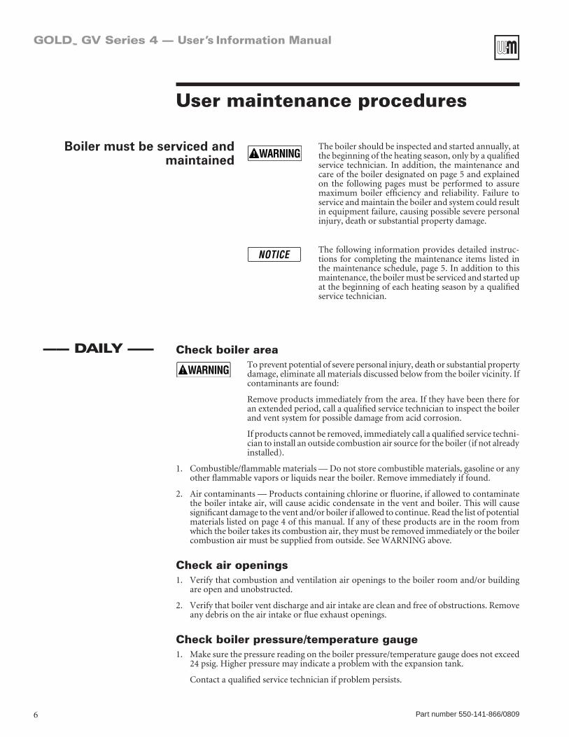
Check boiler area To prevent potential of severe personal injury, death or substantial property
damage, eliminate all materials discussed below from the boiler vicinity. If contaminants are found:
Remove products immediately from the area. If they have been there for an extended period, call a qualified service technician to inspect the boiler and vent system for possible damage from acid corrosion.
If products cannot be removed, immediately call a qualified service techni-cian to install an outside combustion air source for the boiler (if not already installed).
1. Combustible/flammablematerials—Donotstorecombustiblematerials,gasolineoranyotherflammablevaporsorliquidsneartheboiler.Removeimmediatelyiffound.
2. Aircontaminants—Productscontainingchlorineorfluorine,ifallowedtocontaminatethe boiler intake air, will cause acidic condensate in the vent and boiler. This will cause significant damage to the vent and/or boiler if allowed to continue. Read the list of potential materials listed on page 4 of this manual. If any of these products are in the room from which the boiler takes its combustion air, they must be removed immediately or the boiler combustionairmustbesuppliedfromoutside.SeeWARNINGabove.
Check air openings1. Verify that combustion and ventilation air openings to the boiler room and/or building
are open and unobstructed.
2. Verify that boiler vent discharge and air intake are clean and free of obstructions. Remove anydebrisontheairintakeorflueexhaustopenings.
Check boiler pressure/temperature gauge1. Make sure the pressure reading on the boiler pressure/temperature gauge does not exceed
24 psig. Higher pressure may indicate a problem with the expansion tank.
Contactaqualifiedservicetechnicianifproblempersists.
Boiler must be serviced and maintained
User maintenance procedures
The boiler should be inspected and started annually, at the beginning of the heating season, only by a qualified service technician. In addition, the maintenance and care of the boiler designated on page 5 and explained on the following pages must be performed to assure maximum boiler efficiency and reliability. Failure to service and maintain the boiler and system could result in equipment failure, causing possible severe personal injury, death or substantial property damage.
The following information provides detailed instruc-tions for completing the maintenance items listed in the maintenance schedule, page 5. In addition to this maintenance, the boiler must be serviced and started up at the beginning of each heating season by a qualified service technician.
—— DAILY ——

Part number 550-141-866/0809 7
GOLD™ GV Series 4 — User’s Information Manual
Check boiler interior piping1. Remove boiler jacket top.
2. Visually inspect for leaks around internal piping, circulators, relief valve and other fittings. Immediately call a qualified service technician to repair any leaks.
Haveleaksfixedatoncebyaqualifedservicetechnician.Continualfreshmakeup water will reduce boiler life. Minerals can build up in sections, reducing heat transfer, overheating cast iron, and causing section failure.
Do not use petroleum-based cleaning or sealing compounds in boilersystem.Severedamagetoboilerandsystemcomponentscanoccur,resulting in possible severe personal injury, death or substantial property damage.
— MONTHLY —
User maintenance procedures (cont.)
Check venting system1. Visuallyinspectthefluegasventpipingforanysignsofblockage,leakageordeterioration
ofthepiping.Notifyyourqualifiedservicetechnicianatonceifyoufindanyproblem.
Failure to inspect the vent system as noted above and have them repaired by a qualifed service technician can result in vent system failure, causing severe personal injury or death.
Check automatic air vents (if used — use automatic air vents with diaghragm-type expansion tanks only)1. SeeFigure1.
2. Remove the cap from any automatic air vent in the system and check operation by depress-ingvalve“B”slightlywiththetipofascrewdriver.
3. Iftheairventvalveappearstobeworkingfreelyandnotleaking,replacecap“A”,twistingall the way on.
4. Loosencap“A”oneturntoallowventtooperate.
5. Have vent replaced if it does not operate correctly.
Figure 1 Automatic air vent
85036
A
B

8 Part number 550-141-866/0809
GOLD™ GV Series 4 — User’s Information Manual
Check condensate drain system1. While the boiler is running check the discharge end of the condensate drain tubing.
2. Makesurenofluegasisescapingfromthecondensatedraintubingbyholdingyourfingersin front of the tubing discharge.
3. Ifyoudonoticefluegasescapingfromthedraintubing,thisindicatesadrydraintrap.CallyourqualifiedservicetechniciantoinstallaWeil-McLaincondensatedrainlinecheckvalve kit.
UndersomecircumstancesaGVventsystemmaynotproduceenoughcondensate to keep the condensate trap full of liquid. If the trap is not full, smallamountsofflueproductscanbeemittedintotheboilerroomthroughthecondensatedrainline.Contactaqualifiedservicetechniciantoinstalla Weil-McLain condensate drain line check valve kit.
4. Verifythatthecondensatedraintubingisunobstructedbysqueezingit.Checktheentirelength of the condensate drain tubing, including the corrugated tube between the boiler vent outlet tee and the boiler jacket side.
Check boiler relief valve1. Inspect the boiler relief valve and the relief valve discharge pipe for signs of weeping or
leakage.
2. If the relief valve often weeps, the expansion tank may not be working properly. Immedi-ately contact your qualified service technician to inspect the boiler and system.
— MONTHLY —
Test low water cutoff (if installed)1. If the system is equipped with a low water cutoff, test the low water cutoff periodically
during the heating season, following the low water cutoff manufacturer’s instructions.
Clean vent termination & air intake screens1. Removealllintanddebrisfromboththeboilerairintakescreenandthefluedischarge
screen.
2. Theboilercontrolmodulewillsenseblockageoftheairintakeorflueandlockoutiftheblockageisexcessive.Itwillsignalthefailurebyflashingtheappropriateindicatorlightson the control board.
3. If removing the debris does not allow the boiler to operate correctly afterwards, contact your qualifed service technician to inspect the boiler and vent/air systems.
PERIODICALLY
User maintenance procedures (cont.)

Part number 550-141-866/0809 9
GOLD™ GV Series 4 — User’s Information Manual
Operate boiler relief valve1. Before proceeding, verify that the relief valve outlet has been piped to a safe place of dis-
charge, avoiding any possibility of scalding from hot water.
To avoid water damage or scalding due to valve operation, a metal discharge line must be connected to relief valve outlet and run to a safe place of dis-posal. This discharge line must be installed by a qualifed heating installer or service technician in accordance with the instructions in the GV Boiler Manual. The discharge line must be terminated so as to eliminate possibility of severe burns should the valve discharge.
2. Read the boiler pressure/temperature gauge to make sure the system is pressurized.
3. Lift the relief valve top lever slightly, allowing water to relieve through the valve and dis-charge piping.
4. Ifwaterflowsfreely,releasetheleverandallowthevalvetoseat.Watchtheendofthereliefvalve discharge pipe to ensure that the valve does not weep after the line has had time to drain. If the valve weeps, lift the seat again to attempt to clean the valve seat. If the valve continues to weep afterwards, contact your qualified service technician to inspect the valve and system.
5. If water does not flow from the valve when you lift the lever completely, the valve ordischarge line may be blocked. Immediately shutdown the boiler, following the lighting instructionsontheinsidejackettop.Callyourqualifiedservicetechniciantoinspecttheboiler and system.
EvERY 6 MONTHS
Follow boiler shutdown procedure1. Follow“TO TURN OFF GAS TO APPLIANCE” on the Lighting instruction on the inside
ofthejackettoppanel.Youwillalsofindtheseinstructionsonpage12ofthismanual.
2. Do not drain system unless exposure to freezing temperatures will occur.
3. Do not drain the system if it is filled with an antifreeze solution.
4. Do not shut down boilers used for domestic water heating. They must operate year-round.
ENDOF SEASON
User maintenance procedures (cont.)
Oil blower motor1. Remove the jacket top panel to access the blower
motor.
2. UseonlyS.A.E.20motoroil.DONOTusehouse-hold universal oils.
UseonlyS.A.E.20motoroiltolu-bricate the blower motor. Do not use common universal household oils.
3. SeeFigure2.
4. Place a few drops of oil in each of the two oiler cups on the side of the blower motor.
Figure 2 Blower motor

10 Part number 550-141-866/0809
GOLD™ GV Series 4 — User’s Information Manual
① Control moduleTheGOLDControlModule(GCM)respondstosignalsfromtheroomthermostat,airpressureswitch, inlet water sensor and boiler limit circuit to operate the circulators, gas valve, igniter andblower.Whenaroomthermostatcallsforheat,theGCMstartsthesystemcirculatorandblower.
TheGCMrunstheblowerlongenoughtopurgetheboilerfluepassages,thenturnsontheigniterand lets it warm up.
Aftera15-secondwarmup,theGCMopensthegasvalve,turnstheigniteroff,andchecksforflame.Theflamemustcomeonwithin4secondsortheGCMwillshutdownandtrythefullcycle again.
Whentheroomthermostatissatisfied,theGCMturnsofftheboilercomponentsandwaitsforthe next heat call.
TheGCMindicatorlightsshownormalsequencewhenthelightsareonsteady.Whenaproblemoccurs,theGCMflashescombinationsof lightswhichindicatethemost likelyreasonfortheproblem.
② TransformerThe control transformer reduces line voltage to 24 volts for the gas valve and limit circuit.
③ BlowerThe blower pulls in air and mixes it with gas from the gas valve. The blower forces this mixture into the burner for combustion inside the boiler chamber.
④ Air pressure switchThe air pressure switch signals the control module, telling the control module whether air is moving through the blower.
⑤ Water temperature limit switchThe water temperature limit switch turns off the gas valve if the temperature in the boiler goes above its setting. (The circulators will continue to run as long as there is a call for heat.)
⑥ System circulatorThesystemcirculatorcirculateswaterthroughtheexternal(system)piping.TheflowrateofthecirculatoriscontrolledbytheGCM,dependingonthetemperatureofthewaterenteringtheboilersections.Pumpmustremainonboiler—donotremove.
⑦ Bypass circulatorTheGCMoperatesthebypasscirculatortomixhotwaterfromtheboileroutletwithcolderreturnwaterfromthesystemwhenneededtopreventcondensationoffluegasesintheboiler.
Whenthewaterreturningtotheboilerisbelow140°F,theGCMregulatesthebypasscirculatorandsystemcirculatorflowratestoraisethewatertemperatureupto140°Fbeforeitenterstheboilersections.Bybalancingtheseflowrates,theGCMcanprotectagainstcondensationevenifreturnwaterisaslowas60°F.
Pumpmustremainonboiler—donotremove.
⑧ Water temperature sensorThe water temperature sensor monitors the temperature of the water entering the boiler sections. ThesensorsendsthisinformationtotheGCM,tellingtheGCMhowmuchtoadjustthecircula-torflowratestoprovideatleast140°Fenteringwater.
How the boiler works . . .

Part number 550-141-866/0809 11
GOLD™ GV Series 4 — User’s Information Manual
GOLD GV Water boiler — Series 4
12 Part number 550-141-866/0809
GOLD™ GV Series 4 — User’s Information Manual
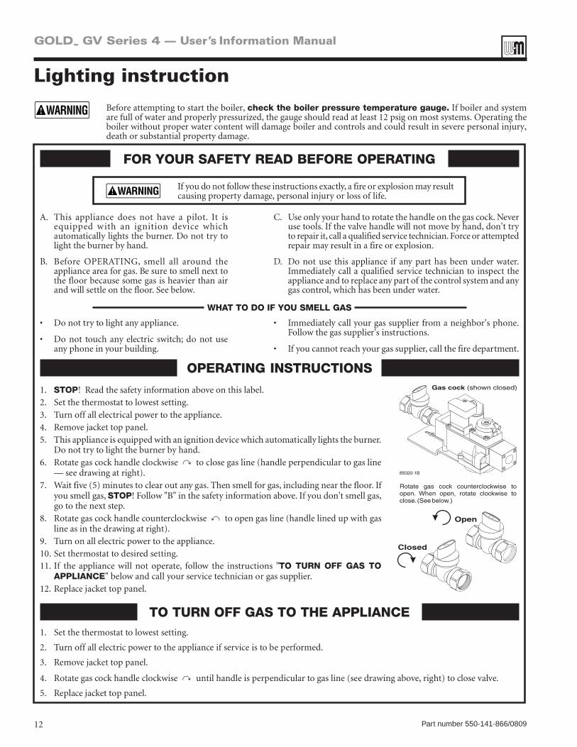
Lighting instruction
Before attempting to start the boiler, check the boiler pressure temperature gauge. If boiler and system arefullofwaterandproperlypressurized,thegaugeshouldreadatleast12psigonmostsystems.Operatingtheboiler without proper water content will damage boiler and controls and could result in severe personal injury, death or substantial property damage.

Part number 550-141-866/0809 13
GOLD™ GV Series 4 — User’s Information Manual

Symptom Common Causes Possible Corrections
Rapid cycling — boiler turns on and off frequently
Thermostat installed where drafts or heat affect reading
Locate thermostat on inner wall away from heat sources or cool drafts.
Heat anticipator in thermostat adjusted incorrectly
Adjust thermostat per manufacturer’s instructions.
Incorrect limit setting Set limit according to system needs. Maximum setting is 220˚F. Increase limit setting to decrease cycling.
Insufficient water flow through boiler
Check all valves to and from boiler. Return to proper setting.
Confirm circulator size.
Frequent release of water through relief valve
Expansion tank sized too small Call qualified service technician to check expansion tank operation and size.
Flooded expansion tank Call qualified service technician to check expansion tank operation.
Inoperative limit control Call qualified service technician to replace limit control.
Need to frequently add makeup water
Leaks in boiler or piping Have qualified service technician repair leaks at once to avoid constant use of makeup water. Makeup water can cause mineral deposits which, in turn, can cause boiler section failure. Do not use petroleum-base stop-leak compounds.
Black water condition Oxygen corrosion due to leaks in boiler and piping
Have qualified service technician repair at once. Keep pH of water between 7.0 to 8.5.
14 Part number 550-141-866/0809
GOLD™ GV Series 4 — User’s Information Manual
Common problems and solutions

Symptom Common Causes Possible Corrections
Popping or percolating noise heard in boiler
Mineral deposits in sections due to constant use of makeup water
Call qualified service technician to de-lime boiler, if necessary. In some cases, deposits will be too heavy to remove with de-liming procedures.
Have qualified service technician repair leaks to eliminate need for constant makeup water.
Incorrect pH of boiler water Call qualified service technician to check pH level and correct. pH should be maintained between 7.0 to 8.5.
Insufficient water flow through boiler
Check all valves to and from boiler. Return to proper setting.
Confirm circulator size.
Metal flakes found in vent outlet or vent starter tee — flueway corrosion
Contaminated combustion air supply — See page 4 in this manual.
Remove any contaminating products. See page 4 in this manual.
Provide outside air for combustion. Have qualified service technician pipe-up kit.
Condensation of combustion gases in boiler sections
Have qualified service technician check operation of mixing system. Repair/replace if necessary.
Some radiators or baseboard units do not heat or are noisy
Air in system Bleed air from system through air vents in radiators or baseboard units.
Low system pressure Fill to correct pressure.
Check for leaks in boiler or piping. Have qualified service technician repair at once.
High limit set too low Adjust high limit to higher setting.
Part number 550-141-866/0809 15
GOLD™ GV Series 4 — User’s Information Manual
Common problems and solutions (continued)

16 Part number 550-141-866/0809