goto products focused delivery program - bosch rexroth · goto products focused delivery program...
TRANSCRIPT

GoTo ProductsFocused Delivery Program
Electric Drivesand Controls
Linear Motion and Assembly Technologies
Pneumatics
Hydraulics

Electric Drives and Controls GoTo 74460 EN1012Bosch Rexroth Corporation2
Electric Drives and Controls GoTo Catalog
Bosch Rexroth is pleased to provide our Automation GoTo Product catalog as part of our GoTo Focused Delivery Program. The GoTo Program provides you with fast delivery of the industry’s most widely used automation products, and lets you “go to” quick reference web pages for more information, technical specifications and ordering details.
Bosch Rexroth Corporation, Electric Drives and Controls Distributor List
For additional information on the GoTo Program and a complete list of other quality Rexroth products available in the Focused Delivery Program just go to:www.boschrexroth-us.com/GoTo
Maine
VTNH
New York
Pennsylvania
MA
NJ
DEMD
CT RISouth Dakota
Iowa
Nebraska
Kansas MissouriColorado
New Mexico
Texas
OklahomaArkansas
Louisiana
North Dakota
Minnesota
Wisconsin
Michigan
IndianaOhio
Kentucky
Virginia
WestVirginia
North Carolina
South Carolina
Mississippi
MI Upper Peninsula
Wyoming
Montana
Idaho
Utah
Arizona
Washington
Oregon
Nevada
California
Tennessee
Alabama
Georgia
Florida
Illinois
Alaska
HawaiiPuerto Rico
AAP Automation2901 S. Tejon St. Englewood, CO 80110 (303) 778-0800www.aapautomation.com
CMA/Flodyne/Hydradyne3265 Gateway Road, Suite. 300 Brookfield, WI 53045 (262) 781-1815www.cmafh.com
Livingston & Haven, LLC11529 Wilmar Blvd Charlotte, NC 28273 (704) 588-3670www.lhtech.com
Womack Machine Supply Co.13835 Senlac Drive Farmers Branch, TX 75234(800) 569-9801 www.womackmachine.com
ACP Automation, LLC10052 Commerce Park Drive Cincinnati, OH 45246 (513) 777-7075www.acpautomation.com
CMA/Flodyne/Hydradyne1000 Muirfield Drive Hanover Park, IL 60133 (630) 563-3600www.cmafh.com
Morrell, Inc.3333 Bald Mountain Road Auburn Hills, MI 48326(248) 373-1600www.morrellinc.com
Womack Machine Supply Co.1615 Yeager Ave LaVerne, CA 91750 (909) 593-7304www.womackmachine.com
Airline Hydraulics Corp.3557 Progress Drive Bensalem, PA 19020 (215) 638-4700www.airlinehyd.com
Gulf Controls Company, LLC5201 Tampa W. Blvd Tampa, FL 33634 (813) 884-0471www.gulfcontrols.com
Motion Tech Automation, Inc.7166 4th Street North Oakdale, MN 55128 (651) 730-9010www.motiontech.com
Womack Machine Supply Co.4272 West Nike Drive West Jordan, UT 84088 (801) 566-4333www.womackmachine.com
Bosch Rexroth Corporation Eastern Regional Office99 Rainbow Road East Granby, CT 06026 (860) 844-8377www.boschrexroth-us.com
Hydrotech, Inc. DynaDrive Division135 East Ascot Lane Cuyahoga Falls, OH 44223 (330) 920-6290www.hydrotech.com
Northwest Motion, Inc.815 7th Ave NW Issaquah, WA 98027 (425) 837-9150www.nwmotion.com
Bosch Rexroth Corporation Western Regional Office7901 Stoneridge Drive, Suite 220 Pleasanton, CA 94588 (925) 227-1074www.boschrexroth-us.com
HiTech Automation, Inc.914 South Highway Drive Fenton, MO 63026 (636) 305-9988www.hitech-automation.com
Womack Machine Supply Co.1417 Forestdale Blvd. Birmingham, AL 35214 (205) 798-9440www.womackmachine.com
74460 EN1012 Electric Drives and Controls GoTo Bosch Rexroth Corporation 3
GoTo Focused Delivery Program
The GoTo Focused Delivery Program streamlines everything to make it easier for you to get a selection of our most popular Rexroth products faster. You’ll benefit from quicker access to product information, reliable lead times that meet or beat the expectations of the market, simplified pricing and enhanced
customer service. Go to our website at: www.boschrexroth-us.com/GoTo for information on GoTo products from among all of Rexroth’s technologies. It’s the fastest and easiest way to get started on your next application.
WARNING!
Failure, improper selection or improper use of the products and/or systems described herein or of related items may cause personal injury or property damage.
This document and other information from Bosch Rexroth Corporation and its divisions provide products and/or system options for further investigation by users having technical expertise. It is important that you analyze all aspects of your application and review the information concerning the products or systems in Rexroth’s Data Sheets. Due to the variety of operating conditions and applications for these products or systems, the user, through his own analysis and testing, is solely responsible for making the final selection of the products and systems, and assuring that all performance, safety and warning requirements are met.
The products described herein, including without limitation, product features, specifications, designs and pricing are subject to change at anytime without notice.
• Current GoTo program content and guidelines are specified at: www.boschrexroth-us.com/GoTo
• How to Order: Please state clearly for each line item on the purchase order that GoTo lead times are required.
• Orders for products exceeding the current program quantity limits may be acknowledged with extended delivery.
• Items listed in this catalog will be shipped from your local distributor or Bosch Rexroth location within the time frame stated in this catalog. For urgent delivery requirements, please check with your local sales office.
• Order via the Rexroth Distributors listed on the inside front cover.
All items subject to prior sale. It is advisable to confirm critical delivery requirements at time of order. All sales subject to Bosch Rexroth Corporation Terms & Conditions of sales, which you can read at: www.boschrexroth-us.com/terms
Bosch Rexroth reserves the right to make program changes at any time without notice.
GoTo Program Delivery Conditions
Distributed by:
For our complete product portfolio please visit our website at: www.boschrexroth-us.com and select “Products and Solutions”
or call 1.800.REXROTH (739-7684)


74460 EN1012 Electric Drives and Controls GoTo Bosch Rexroth Corporation 5
Table of Contents
Liability:In no event can the manufacturer accept warranty claims or liability claims for damages resulting from improper use or misuse of the equipment or as a result of changes made to the equipment other than those authorized by the manufacturer. The manufacturer will accept no claim in which non-original spare parts have been used.
©2012, Bosch Rexroth CorporationAll rights are held by ROBERT BOSCH GMBH and BOSCH REXROTH CORPORATION, also regarding patent claims. We reserve the right to make technical changes at any time without notice. Errors and omissions excepted.
Page No.
Drive Systems
Drives (IndraDrive Cs, IndraDrive C) 7Motors (IndraDyn S) 11Additional Components 14Cables 15
Motion Control PAC
IndraControl L 17IndraMotion MLC 18
I/O
Inline – Cabinet Mount (IP20)
Power Modules 19Bus Couplers 20Block I/O 21Digital Input Modules 23Digital Output Modules 24Analog Input Modules 26Analog Output Modules 27Temperature Modules 28Communication Modules 29Motion and Counter Modules 30

Electric Drives and Controls GoTo 74460 EN1012Bosch Rexroth Corporation6
Table of Contents (continued)
Page No.
IndraControl S67 – Machine Mount (IP67)
Power Divider 31Bus Coupler 32Digital Input Modules (M8, M12) 34Digital Output Modules (M8, M12) 36Analog Input Modules (M12) 38Analog Output Modules (M12) 40Temperature Modules (M12) 42Cables and Connectors 44
HMI
Standard HMI 45WinCE-based HMI 46
Software
IndraWorks 47VI-Composer 48
Part Numbers 49
Liability:In no event can the manufacturer accept warranty claims or liability claims for damages resulting from improper use or misuse of the equipment or as a result of changes made to the equipment other than those authorized by the manufacturer. The manufacturer will accept no claim in which non-original spare parts have been used.
©2012, Bosch Rexroth CorporationAll rights are held by ROBERT BOSCH GMBH and BOSCH REXROTH CORPORATION, also regarding patent claims. We reserve the right to make technical changes at any time without notice. Errors and omissions excepted.
74460 EN1012 Electric Drives and Controls GoTo Bosch Rexroth Corporation 7
GoTo Focused Delivery Program: Drive Systems
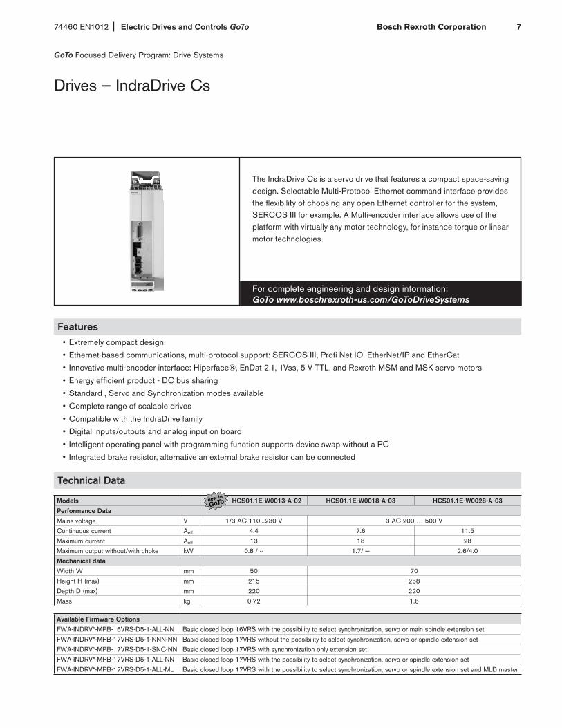
Drives – IndraDrive Cs
The IndraDrive Cs is a servo drive that features a compact space-saving design. Selectable Multi-Protocol Ethernet command interface provides the flexibility of choosing any open Ethernet controller for the system, SERCOS III for example. A Multi-encoder interface allows use of the platform with virtually any motor technology, for instance torque or linear motor technologies.
For complete engineering and design information: GoTo www.boschrexroth-us.com/GoToDriveSystems
Features• Extremely compact design
• Ethernet-based communications, multi-protocol support: SERCOS III, Profi Net IO, EtherNet/IP and EtherCat
• Innovative multi-encoder interface: Hiperface®, EnDat 2.1, 1Vss, 5 V TTL, and Rexroth MSM and MSK servo motors
• Energy efficient product - DC bus sharing
• Standard , Servo and Synchronization modes available
• Complete range of scalable drives
• Compatible with the IndraDrive family
• Digital inputs/outputs and analog input on board
• Intelligent operating panel with programming function supports device swap without a PC
• Integrated brake resistor, alternative an external brake resistor can be connected
Technical Data
Models HCS01.1E-W0013-A-02 HCS01.1E-W0018-A-03 HCS01.1E-W0028-A-03Performance DataMains voltage V 1/3 AC 110...230 V 3 AC 200 … 500 V
Continuous current Aeff 4.4 7.6 11.5
Maximum current Aeff 13 18 28
Maximum output without/with choke kW 0.8 / -- 1.7/ — 2.6/4.0
Mechanical dataWidth W mm 50 70
Height H (max) mm 215 268
Depth D (max) mm 220 220
Mass kg 0.72 1.6
Available Firmware OptionsFWA-INDRV*-MPB-16VRS-D5-1-ALL-NN Basic closed loop 16VRS with the possibility to select synchronization, servo or main spindle extension set
FWA-INDRV*-MPB-17VRS-D5-1-NNN-NN Basic closed loop 17VRS without the possibility to select synchronization, servo or spindle extension set
FWA-INDRV*-MPB-17VRS-D5-1-SNC-NN Basic closed loop 17VRS with synchronization only extension set
FWA-INDRV*-MPB-17VRS-D5-1-ALL-NN Basic closed loop 17VRS with the possibility to select synchronization, servo or spindle extension set
FWA-INDRV*-MPB-17VRS-D5-1-ALL-ML Basic closed loop 17VRS with the possibility to select synchronization, servo or spindle extension set and MLD master
Electric Drives and Controls GoTo 74460 EN1012Bosch Rexroth Corporation8
GoTo Focused Delivery Program: Drive Systems
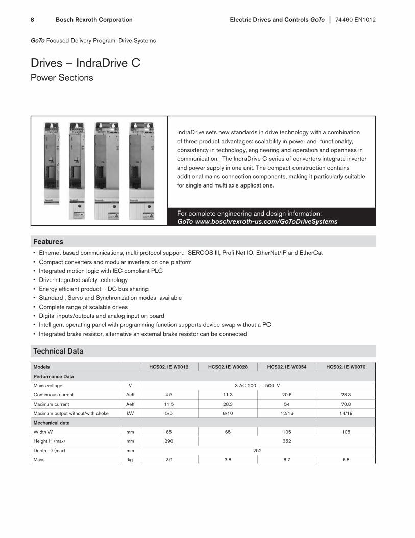
Drives – IndraDrive CPower Sections
IndraDrive sets new standards in drive technology with a combination of three product advantages: scalability in power and functionality, consistency in technology, engineering and operation and openness in communication. The IndraDrive C series of converters integrate inverter and power supply in one unit. The compact construction contains additional mains connection components, making it particularly suitable for single and multi axis applications.
For complete engineering and design information: GoTo www.boschrexroth-us.com/GoToDriveSystems
Features• Ethernet-based communications, multi-protocol support: SERCOS III, Profi Net IO, EtherNet/IP and EtherCat• Compact converters and modular inverters on one platform• Integrated motion logic with IEC-compliant PLC• Drive-integrated safety technology• Energy efficient product - DC bus sharing• Standard , Servo and Synchronization modes available• Complete range of scalable drives• Digital inputs/outputs and analog input on board• Intelligent operating panel with programming function supports device swap without a PC• Integrated brake resistor, alternative an external brake resistor can be connected
Technical Data
Models HCS02.1E-W0012 HCS02.1E-W0028 HCS02.1E-W0054 HCS02.1E-W0070
Performance Data
Mains voltage V 3 AC 200 … 500 V
Continuous current Aeff 4.5 11.3 20.6 28.3
Maximum current Aeff 11.5 28.3 54 70.8
Maximum output without/with choke kW 5/5 8/10 12/16 14/19
Mechanical data
Width W mm 65 65 105 105
Height H (max) mm 290 352
Depth D (max) mm 252
Mass kg 2.9 3.8 6.7 6.8
74460 EN1012 Electric Drives and Controls GoTo Bosch Rexroth Corporation 9
GoTo Focused Delivery Program: Drive Systems
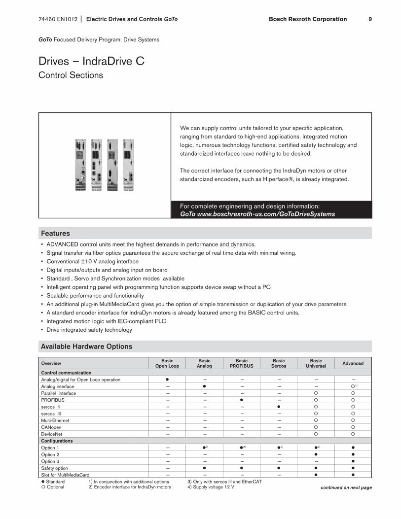
Drives – IndraDrive CControl Sections
We can supply control units tailored to your specific application, ranging from standard to high-end applications. Integrated motion logic, numerous technology functions, certified safety technology and standardized interfaces leave nothing to be desired.
The correct interface for connecting the IndraDyn motors or other standardized encoders, such as Hiperface®, is already integrated.
For complete engineering and design information: GoTo www.boschrexroth-us.com/GoToDriveSystems
Features• ADVANCED control units meet the highest demands in performance and dynamics.• Signal transfer via fiber optics guarantees the secure exchange of real-time data with minimal wiring.• Conventional ±10 V analog interface• Digital inputs/outputs and analog input on board• Standard , Servo and Synchronization modes available• Intelligent operating panel with programming function supports device swap without a PC• Scalable performance and functionality• An additional plug-in MultiMediaCard gives you the option of simple transmission or duplication of your drive parameters.• A standard encoder interface for IndraDyn motors is already featured among the BASIC control units.• Integrated motion logic with IEC-compliant PLC• Drive-integrated safety technology
Available Hardware Options
Overview BasicOpen Loop
Basic Analog
Basic PROFIBUS
Basic Sercos
Basic Universal Advanced
Control communicationAnalog/digital for Open Loop operation l — — — — — Analog interface — l — — — 1)
Parallel interface — — — —
PROFIBUS — — l —
sercos II — — — l
sercos III — — — —
Multi-Ethernet — — — —
CANopen — — — —
DeviceNet — — — —
ConfigurationsOption 1 — l2) l2) l2) l2) l
Option 2 — — — — l l
Option 3 — — — — — l
Safety option — l l l l l
Slot for MultiMediaCard — — — — l l
l Standard 1) In conjunction with additional options 3) Only with sercos III and EtherCAT Optional 2) Encoder interface for IndraDyn motors 4) Supply voltage 12 V continued on next page

Electric Drives and Controls GoTo 74460 EN1012Bosch Rexroth Corporation10
GoTo Focused Delivery Program: Drive Systems
Drives – IndraDrive C (continued)Control Sections
Available Hardware Options (continued)
Encoder interfacesIndraDyn motors MSK, MKE, MAD and MAF, Hiperface®, 1 Vpp and 5 V TTL4)
— l l l l
MHD and MKD motors — — — —
EnDat 2.1, 1 Vpp — — — —
Safety options compliant with EN 13849-1 and EN 62061 Safe Torque Off (category 3 PL e/SIL 3) —
Safe Motion (category 3 PL d/SIL 2) — — — — —
ExtensionsEncoder emulation — l — —
Analog I/O extension — — — —
Digital I/O extension — — — — —
Digital I/O with SSI interface — — — — —
Cross communication — — — — —
Software moduleMultiMediaCard — — — —
Operator panelStandard l l l l l l
Cycle times Current control [µs] 125 62.5Speed control [µs] 250 125Position control [µs] 500 250PWM frequency4/8 kHz l/l l/l l/l l/l l/l l/l12/16 kHz —/— —/— —/— —/— —/— l/lInputs/outputsDigital inputs/of which utilizable for probes 8/— 5/— 5/1 5/1 5/1 7/2 Digital inputs/outputs (user-defined settings) — 4 3 3 3 4 Analog inputs 2 2 — — — 1 Analog outputs 2 — — — — 2 Relay outputs 3 1 1 1 1 1 InterfacesRS232 l l l l l l
Control voltage dataControl voltage [V] DC 24Power consumption without options [W] 7.5 8 7.5 7.5 6.5 6 Continuous current without options [A] 0.31 0.33 0.31 0.31 0.27 0.25 l Standard 1) In conjunction with additional options 3) Only with sercos III and EtherCAT Optional 2) Encoder interface for IndraDyn motors 4) Supply voltage 12 V
Available Firmware Options
FWA-INDRV*-MPB-05VRS-D5-1-NNN-NN Basic closed loop 05VRS without the possibility to select synchronization, servo or main spindle extension setFWA-INDRV*-MPB-05VRS-D5-1-SNC-NN Basic closed loop 05VRS with synchronization only extension setFWA-INDRV*-MPB-07VRS-D5-0-NNN-NN Basic open loop 07VRS FWA-INDRV*-MPB-07VRS-D5-1-NNN-NN Basic closed loop 07VRS without the possibility to select synchronization, servo or main spindle extension setFWA-INDRV*-MPB-07VRS-D5-1-SNC-NN Basic closed loop 07VRS with synchronization extension setFWA-INDRV*-MPC-07VRS-D5-1-SNC-ML Advanced closed loop 07VRS with synchronization extension set for MLD master (software module PFM…-FW reqd.)FWA-INDRV*-MPC-07VRS-D5-1-ALL-MA Advanced closed loop 07VRS with all extension sets for MLD master (software module PFM…-FW required)
Software module
MultiMediaCard - PFM02.1-016-FWOptional with Basic Universal and Advanced control sectionsRequired for control sections and MPC-firmware with MLD master
74460 EN1012 Electric Drives and Controls GoTo Bosch Rexroth Corporation 11
GoTo Focused Delivery Program: Drive Systems
Motors – IndraDyn SMSK Motor
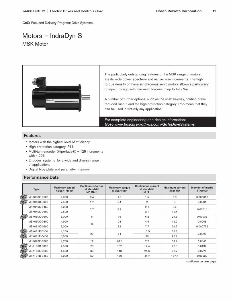
The particularly outstanding features of the MSK range of motors are its wide power spectrum and narrow size increments. The high torque density of these synchronous servo motors allows a particularly compact design with maximum torques of up to 495 Nm.
A number of further options, such as the shaft keyway, holding brake, reduced runout and the high protection category IP65 mean that they can be used in virtually any application.
For complete engineering and design information: GoTo www.boschrexroth-us.com/GoToDriveSystems
Features• Motors with the highest level of efficiency• High protection category IP65• Multi-turn encoder (Hiperface®) – 128 increments with 4,096 • Encoder systems for a wide and diverse range of applications • Digital type plate and parameter memory
Performance Data
Type Maximum speednMax (1/min)
Continuous torque at standstill
M0 (Nm)
Maximum torqueMMax (Nm)
Continuous current at standstill
I0 (A)
Maximum currentIMax (A)
Moment of inertiaJ (kgm2)
MSK030C-0900 9,000 0.4 1.8 1.5 6.8 0.000013
MSK040B-0600 7,500 1.7 5.1 2 8 0.0001
MSK040C-0450 6,0002.7 8.1
2.4 9.60.00014
MSK040C-0600 7,500 3.1 12.4
MSK050C-0600 6,000 5 15 6.2 24.8 0.00033
MSK060C-0300 4,9008
24 4.8 19.2 0.0008
MSK061C-0600 6,000 32 7.7 34.7 0.000752
MSK071E-0300 4,20023 84
12.5 56.30.0029
MSK071E-0450 6,000 20 90.1
MSK076C-0300 4,700 12 43.5 7.2 32.4 0.0043
MSK100B-0300 4,500 28 102 17.4 78.3 0.0192
MSK100C-0300 4,500 38 148 21.6 97.2 0.0273
MSK101D-0450 6,000 50 160 41.7 187.7 0.00932
continued on next page

Electric Drives and Controls GoTo 74460 EN1012Bosch Rexroth Corporation12
Dimensional Data
Type A (mm) B (mm) C (mm) Ø D (mm) Ø E (mm) Ø F (mm) Ø G (mm) H (mm) Weight (kg)MSK030C-0900 54 152.5 20 9 40 63 4.5 98.5 1.3MSK040B-0600 82 155.5 30 14 50 95 6.6 124.5 2.8MSK040C-0450
82 185.5 30 14 50 95 6.6 124.5 3.6MSK040C-0600MSK050C-0600 98 203 40 19 95 115 9 134.5 5.4MSK060C-0300 116 226 50 24 95 130 9 156 8.4MSK061C-0600 116 264 40 19 95 130 9 156 8.3MSK071E-0300
140 352 58 32 130 165 11 202 23.5MSK071E-0450MSK076C-0300 140 292.5 50 24 110 165 11 180 13.8MSK100B-0300 192 368 60 32 130 215 14 211.5 34MSK100C-0300 192 434 60 32 130 215 14 211.5 45.1MSK101D-0450 192 410 80 38 180 215 14 262 40
Motors – IndraDyn S (continued)MSK Motor
GoTo Focused Delivery Program: Drive Systems

74460 EN1012 Electric Drives and Controls GoTo Bosch Rexroth Corporation 13
GoTo Focused Delivery Program: Drive Systems
Motors – IndraDyn SMSM Motor
Maintenance-free MSM motors are available in five sizes rated at up to 750 W continuous mechanical power. These short-length motors feature high power density and minimized flange dimensions, making them the ideal choice in a wide range of application scenarios.
The IP54 motors come with an absolute encoder and optional holding brake, and they can easily be connected to IndraDrive Cs power units with a 3 AC 230 V line input.
For complete engineering and design information: GoTo www.boschrexroth-us.com/GoToDriveSystems
Features• Torque up to 7.1 Nm• Speed up to 5,000 rpm• Multi-turn absolute encoder• High dynamic performance• High performance density
Performance Data
TypeRated power Continuous torque
at standstill Maximum torque Maximum speed Moment of inertia
PN (W) M0 (Nm) MMax (Nm) nMax (1/min) J (kgm2)MSM019B 100 0.32 0.95 5,000 0.0000025MSM031B 200 0.64 1.91 5,000 0.0000051MSM031C 400 1.3 3.8 5,000 0.000014MSM041B 750 2.4 7.1 4,500 0.000087
Dimensional Data
Type A (mm) B (mm) 1) C (mm) Ø D (mm) Ø E (mm) Ø F (mm) Ø G (mm) H (mm) Weight (kg) 1)
MSM019B 38 92 / 122 25 8 30 45 3.4 51 0.47 / 0.68MSM031B 60 79 / 115.5 30 11 50 70 4.5 73 0.82 / 1.3MSM031C 60 98.5 / 135 30 14 50 70 4.5 73 1.2 / 1.7MSM041B 80 112 / 149 35 19 70 90 6 93 2.3 / 3.1
1) dimensions with / without brake.

Electric Drives and Controls GoTo 74460 EN1012Bosch Rexroth Corporation14
GoTo Focused Delivery Program: Drive Systems
Additional Components
The NFD line filter. Mains filters ensure that the EMC limit values are adhered to and suppress leakage current generated by line capacitors. Our mains filters are optimally coordinated with the power units and are scalable in regards to current, number of drives and motor cable length. They can be combined with our shielded motor cables for trouble-free operation conforming to EN 61800-3, Class A, Group 2, even with single cable lengths of up to 75 m.
For complete engineering and design information: GoTo www.boschrexroth-us.com/GoToDriveSystems
Technical Data
Main filters for HCS converters
TypeContinuous current Power dissipation Width Height Depth Mass
A W mm mm mm kg
NFD03.1-480-016 16 6.4 55 220 90 1
NFD03.1-480-030 30 11.9 60 270 100 1.4
NFD03.1-480-055 55 25.9 90 220 105 2
Accessories
Basic accessories HAS01 The basic accessories contain all the mounting parts and fixing elements for installing the HCS02.1 drive controllers (not needed for HCS01.1)
Shield connection HAS02 The shield connection plate is an EMC-compatible method of connecting the motor power cable to the HCS02.1 drive controllers. It also serves as a cord grip (not needed for HCS01.1).
Connection Points HAS05 Universal adapter for safety technology for easier X41 wiring of 2nd channel
Basic accessories HAS01
Type needed with
HAS01.1-065-NNN-CN HCS02.1...W0012/W0028
HAS01.1-105-NNN-CN HCS02.1...W0054/W0070
Shield connection HAS02
Type needed with
HAS02.1-002-NNN-NN HCS02.1...W0054/W0070
Connection Points HAS05
Type optional (for control sections with L2/S2 safety - X41 adapter )
HAS05.1-007-NNL-NN Adapter from D-Sub to terminal connector – fitting direction: left-hand
HAS05.1-007-NNR-NN Adapter from D-Sub to terminal connector – fitting direction: right-hand

74460 EN1012 Electric Drives and Controls GoTo Bosch Rexroth Corporation 15
Motor Power- and Feedback Cable assemblies for IndraDrive C and Cs drives with IndraDyn S motors in the GoTo program are offered in multiple lengths and are completely assembled with connectors for easy installation.
Interface/Communication cables for connection of control units and system peripherals or start-up/commissioning via PC as described by type.
For complete engineering and design information: GoTo www.boschrexroth-us.com/GoToDriveSystems
GoTo Focused Delivery Program: Drive Systems
Cables
Technical Data
Motor power Cable Length 1)Connecting
Drives Motors
RKL0013/005.0 fixed 5mIndraDrive Cs - HCS01.1…W0013 MSM019,031,041
RKL0013/000.0 configurable 1–75m
RKL0014/005.0 fixed 5mIndraDrive Cs - HCS01.1…W0013 MSK030,040,050,060,061
RKL0014/000.0 configurable 1–75m
RKL0019/005.0 fixed 5m
IndraDrive Cs - HCS01.1…W0018 and W0028 MSK030,040,050,060,061,076RKL0019/010.0 fixed 10m
RKL0019/000.0 configurable 1–75m
RKL4302/005.0 fixed 5m
IndraDrive C - HCS02.1…W0012 and W0028 MSK030,040,050,060,061,076RKL4302/010.0 fixed 10m
RKL4302/000.0 configurable 1–75m
RKL4303/005.0 fixed 5m
IndraDrive C - HCS02.1…W0054 and W0070 MSK030,040,050,060,061,076RKL4303/010.0 fixed 10m
RKL4303/000.0 configurable 1–75m
RKL4309/005.0 fixed 5mIndraDrive C - HCS02.1…W0054 and W0070 MSK071E-300,450
RKL4309/000.0 configurable 1–75m
RKL4324/005.0 fixed 5mIndraDrive C - HCS02.1…W0054 and W0070 MSK100,101
RKL4324/000.0 configurable 1–75m
Motor Feedback Cable Length 1)Connecting
Drives Motors
RKG4200/005.0 fixed 5m
IndraDrive C and Cs any MSK motorRKG4200/010.0 fixed 10m
RKG4200/000.0 configurable 1–75m
RKG0033/005.0 fixed 5mIndraDrive Cs…W0013 MSM019,031,041
RKG0033/000.0 configurable 1–75m
RKG0034/000.0 configurable 1–2m IndraDrive Cs…W0013 MSM019,031,041 for absolute encoder function in conjunction with SUP-E01-MSM-BATTERYBOX
1) Cables marked "fixed" are sized to the length stated; cables marked "configurable" can be ordered based on length needed within the range given and 0.5m increments
continued on next page

Electric Drives and Controls GoTo 74460 EN1012Bosch Rexroth Corporation16
Technical Data (continued)
Interface cable (optical – Sercos II) Length Connecting
RKO0100/00.25 0.25m Drives and peripherals with Sercos II (optical) communication interface, inside cabinet
RKO0101/005.0 5mDrives and peripherals with Sercos II (optical) communication interface, outside cabinet
RKO0101/010.0 10m
Interface cable (Ethernet based) Length Connecting
RKB0011/005.0 5mDrives and peripherals with Sercos III or other Ethernet based communication interface
RKB0013/00.25 0.25m
Interface cable (RS232 - Serial) Length Connecting
IKB0041/002.0 2m A PC or a separate control terminal directly to the RS232 serial interface of the control unit for start-up or operation
Battery box (HCS01.1 - MSM)
SUP-E01-MSM-BATTERYBOX External battery for absolute encoder function with HCS01.1 and MSM, connected in feedback circuit between RKG0033 and MSM or between RKG0033 and optional RKG0034
Cables (continued)
GoTo Focused Delivery Program: Drive Systems

74460 EN1012 Electric Drives and Controls GoTo Bosch Rexroth Corporation 17
GoTo Focused Delivery Program: Motion Control PAC
IndraControl L
IndraControl L the rack-based platform from Rexroth allows easy and consistent automation for all centralized and distributed architectures.
IndraControl L is the flexible configurable hardware platform for open control architectures. Whether you intend to implement a motion control, a CNC or a PLC application – it is always the same hardware you use. Your application is only defined by the software.
For complete engineering and design information: GoTo www.boschrexroth-us.com/GoToMotionControl_PAC
Features• Scalable hardware platform
• Standardized communication interfaces
• Optional expansion through function and technology modules
• Ideal for centralized and distributed control
• Individually expandable with high-grade Human-Machine Interface (HMI) components
• Modular I/O units
Technical Data
Control hardware L40 IndraLogic 1G L25 IndraLogic 2G L45 IndraLogic 2G
Memory
Application: 64 MB 128 MB 256 MB
Retentive memory: 128 kB 256 kB 256 kB
Buffered: 1 MB -- 8 MB
Flash size: 128 MB 1 GB 1 GB
Interfaces
Ethernet: 1 x Ethernet TCP/IP (Standard)
Ready: 1 x ready contact (Standard)
Others --- 2 x Ethernet TCP/IP
I/O
Digital inputs 8 DC-decoupled inputs (with interrupt capability)
--- 8 DC-decoupled inputs (with interrupt capability)
Digital outputs 8 DC-decoupled outputs --- 8 DC-decoupled outputs
Channels, used Max. 256
I/O extension Max. no. of
Inline modules63
Max. no. of bytes 64
Function Modules Max. 4 2 4
Fieldbus
Sercos: 1 x Sercos II 1 x Sercos III
ProfiNet: --- 1 x ProfiNet IO Controller/-Device (Option)
EtherNet/IP: --- 1 x EtherNet/IP Scanner/-Adapter (Option)
Profibus: 1 x Profibus-Master/-Slave --- 1 x Profibus-Master/-Slave

Electric Drives and Controls GoTo 74460 EN1012Bosch Rexroth Corporation18
GoTo Focused Delivery Program: Motion Control PAC
IndraMotion MLC
For complete engineering and design information: GoTo www.boschrexroth-us.com/GoToMotionControl_PAC
IndraMotion MLC is the integrated controller-based system solution from Rexroth. It uses PLC programming according to IEC 61131-3 with object oriented programming such as: Function Block Diagrams (FBD), Ladder Diagrams (LD), Sequential Function Chart (SFC), and Structured Text (ST).
The compact Rexroth IndraMotion MLC motion logic system gives you any freedom you wish for your consistent and modern machine automation. Innovative software and firmware functions, easy engineering and open system interfaces provide maximum flexibility in all motion applications.
Technical Data
Control Hardware MLC L40 MLC L25 MLC L45PLC runtime systemIndraLogic 1G kernel Conforming with IEC 61131-3 • --- ---IndraLogic 2G kernel Conforming with IEC 61131-3 with extensions --- • •Task management
Freely projectable tasks (priority 0-20) Cyclic, free-running, event-controlled, extern event-controlled
8
Cycle-synchronous processing of the I/O process image •sercos III synchronous processing of the I/O process image •min. PLC cycle time Synchronous with system cycle 1 msmin. Motion cycle time Setpoint generator 1 ms 2 ms 1 msPLC processing time
Typical processing time for 1,000 instructions/µsCommand mix (Real, Integer, Bool etc.) 50 35 30Bool-Operation 50 20 30Word-Operation 50 20 30
Motion ControlNumber of axes Real, virtual, encoder, grouping 32 16 32
Synchronization (ELS – electronic line shaft)
real axes (Servo drives) •Virtual axes (Virtual masters) •Encoder axes (Real masters) •real axes (Cross-communication) •Dynamic synchronization •Master axis cascading •
Positioning Single-axis •Electronic gears •
Intermediate point tables (In the drive, max. 1,024 intermediate points)
4
Electronic Motion Profile (in the output drive, motion profiles with max. 16 segments)
2
FlexProfile (In the control, master-/time-based motion profiles with max. 16 segments)
4
Drive systemsIndraDrive • • •IndraDrive Mi Firmware MPB • • •IndraDrive Cs • • •EcoDrive Cs • • •SERCOS Pack-Profile • • •HNC100.3 Hydraulic drive • • •
74460 EN1012 Electric Drives and Controls GoTo Bosch Rexroth Corporation 19
For complete engineering and design information: GoTo www.boschrexroth-us.com/GoToIO
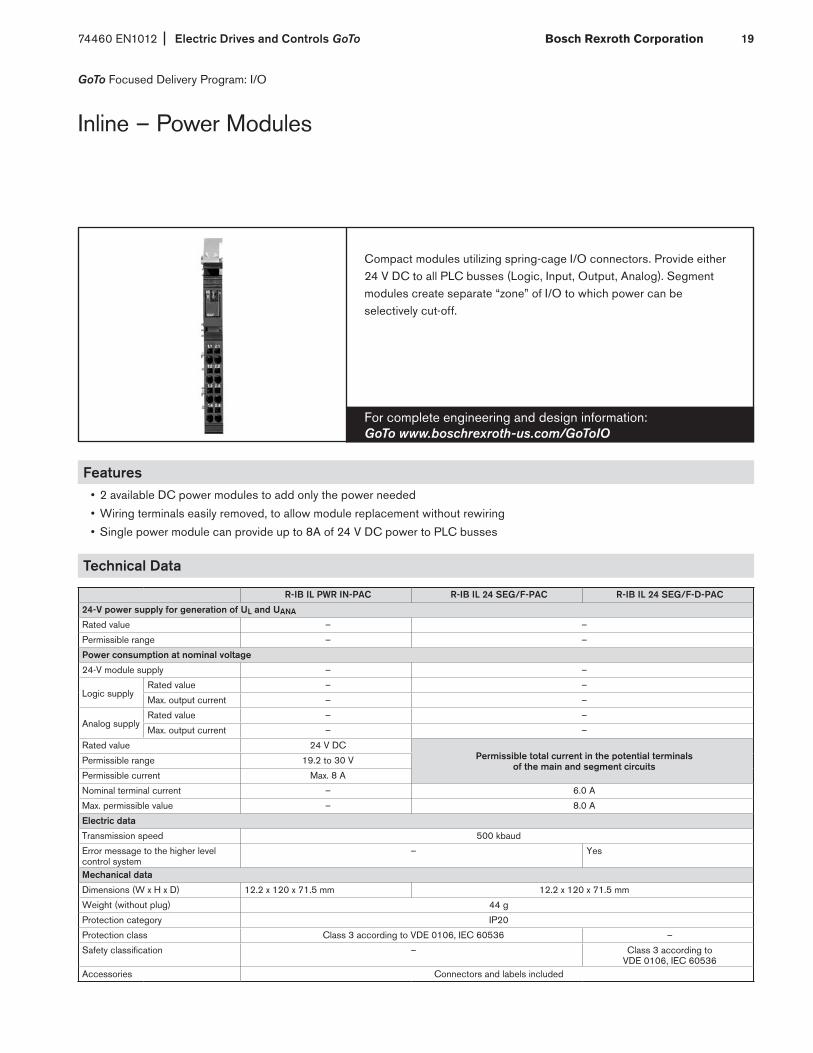
Compact modules utilizing spring-cage I/O connectors. Provide either 24 V DC to all PLC busses (Logic, Input, Output, Analog). Segment modules create separate “zone” of I/O to which power can be selectively cut-off.
Inline – Power Modules
GoTo Focused Delivery Program: I/O
Features• 2 available DC power modules to add only the power needed
• Wiring terminals easily removed, to allow module replacement without rewiring
• Single power module can provide up to 8A of 24 V DC power to PLC busses
Technical Data
R-IB IL PWR IN-PAC R-IB IL 24 SEG/F-PAC R-IB IL 24 SEG/F-D-PAC
24-V power supply for generation of UL and UANA
Rated value – –
Permissible range – –
Power consumption at nominal voltage
24-V module supply – –
Logic supply Rated value – –
Max. output current – –
Analog supplyRated value – –
Max. output current – –
Rated value 24 V DC Permissible total current in the potential terminals
of the main and segment circuits Permissible range 19.2 to 30 V
Permissible current Max. 8 A
Nominal terminal current – 6.0 A
Max. permissible value – 8.0 A
Electric data
Transmission speed 500 kbaud
Error message to the higher level control system
– Yes
Mechanical data
Dimensions (W x H x D) 12.2 x 120 x 71.5 mm 12.2 x 120 x 71.5 mm
Weight (without plug) 44 g
Protection category IP20
Protection class Class 3 according to VDE 0106, IEC 60536 –
Safety classification – Class 3 according to VDE 0106, IEC 60536
Accessories Connectors and labels included

Electric Drives and Controls GoTo 74460 EN1012Bosch Rexroth Corporation20
Features• Wiring terminals easily removed to allow module replacement without rewiring• Sercos III bus coupler for an entire Sercos III fieldbus architechture• Configurable network speeds
Technical Data
R-IL S3 BK DI8 DO4-PAC R-IL PB BK DI8 DO4/CN-PAC R-IL PB BK DP/V1-PACCommunication Interfaces Sercos III PROFIBUS DP PROFIBUS DP
Local bus System data Number of segments per station Max. 63 (incl. 2 at bus coupler) Max. 63Total of all I/O data per station Max. 244 bytes max 176/184 bytes, dep. modeTransmission speed in the local bus 500 kbaud Auto. to master speedDigital outputs Number 4 — Nominal output voltage UOut 24 VDC — Total current 2 A — Protection Short-circuit, overload — Actuator connection type 2-, 3-wire connection — Digital inputs Number 8 — Nominal input voltage UINom 24 VDC — Permissible nominal input voltage range –30 < UINom < +30 VDC — Nominal input current at UINom Typ. 3 mA — Permissible line length 30 m — Sensor connection type 2-, 3-wire connection — Segment feed US/UM Nominal value 24 VDC Tolerances –15/+20 % Load current Max. 8 A Mechanical data Dimensions (W x H x D) 80 x 121 x 70 mm 91 x 120 x 71.5 mm Protection category IP20 Protection class Class 3 according to VDE 0106, IEC 60536 Accessories
Connectors and labels included
For complete engineering and design information: GoTo www.boschrexroth-us.com/GoToIO
Sercos III and Profibus I/O bus couplers available. Bus couplers provide network drops that are expandable with using the same Inline I/O that is used locally with a PLC.
Inline – Bus Couplers
GoTo Focused Delivery Program: I/O
74460 EN1012 Electric Drives and Controls GoTo Bosch Rexroth Corporation 21
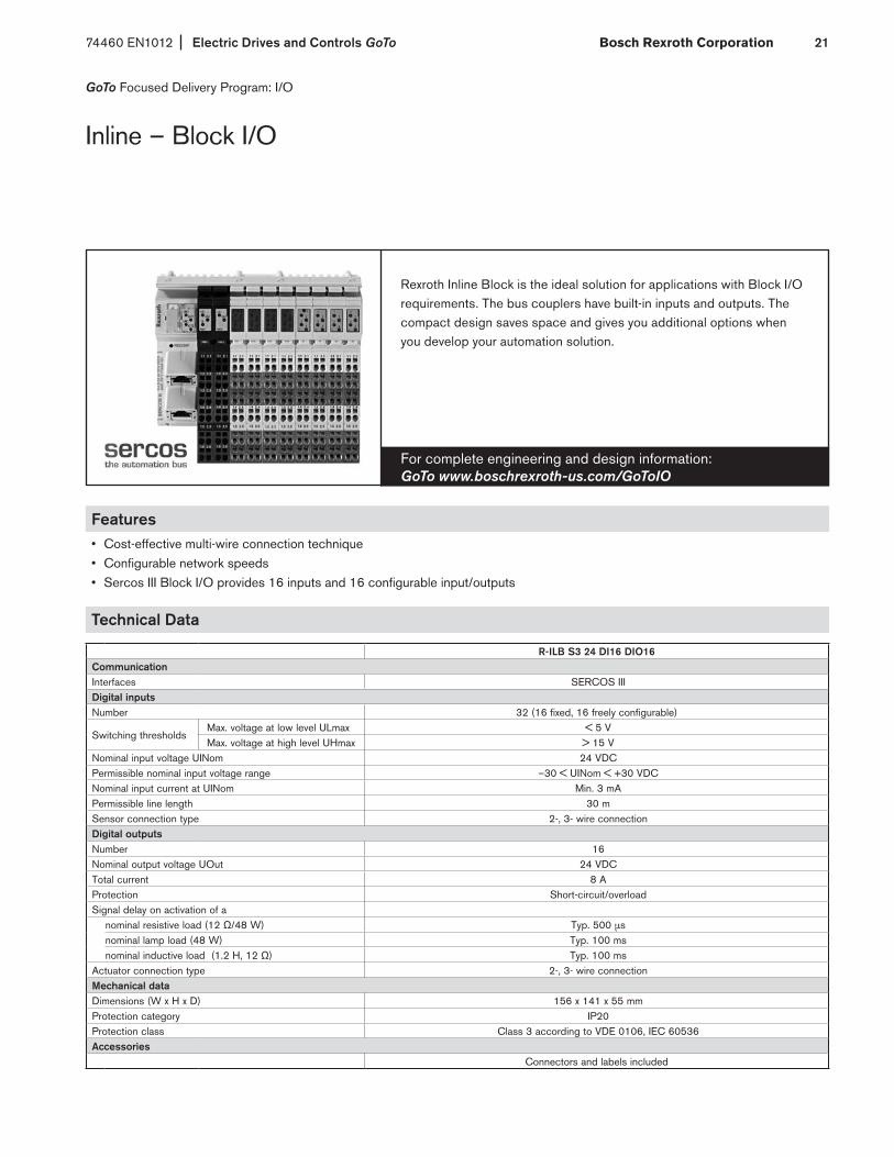
Features• Cost-effective multi-wire connection technique• Configurable network speeds• Sercos III Block I/O provides 16 inputs and 16 configurable input/outputs
Technical Data
R-ILB S3 24 DI16 DIO16Communication Interfaces SERCOS III Digital inputs Number 32 (16 fixed, 16 freely configurable)
Switching thresholds Max. voltage at low level ULmax < 5 V Max. voltage at high level UHmax > 15 V
Nominal input voltage UINom 24 VDCPermissible nominal input voltage range –30 < UINom < +30 VDCNominal input current at UINom Min. 3 mAPermissible line length 30 m Sensor connection type 2-, 3- wire connectionDigital outputsNumber 16Nominal output voltage UOut 24 VDCTotal current 8 AProtection Short-circuit/overloadSignal delay on activation of a
nominal resistive load (12 Ω/48 W) Typ. 500 µsnominal lamp load (48 W) Typ. 100 msnominal inductive load (1.2 H, 12 Ω) Typ. 100 ms
Actuator connection type 2-, 3- wire connectionMechanical dataDimensions (W x H x D) 156 x 141 x 55 mm Protection category IP20Protection class Class 3 according to VDE 0106, IEC 60536 Accessories
Connectors and labels included
For complete engineering and design information: GoTo www.boschrexroth-us.com/GoToIO
Rexroth Inline Block is the ideal solution for applications with Block I/O requirements. The bus couplers have built-in inputs and outputs. The compact design saves space and gives you additional options when you develop your automation solution.
GoTo Focused Delivery Program: I/O
Inline – Block I/O

Electric Drives and Controls GoTo 74460 EN1012Bosch Rexroth Corporation22
Features• 2 x Ethernet twisted pair according to 802.3u with
auto negotiation and auto crossing• Transmission speed of 100 Mbps
• I/O areas can be parameterized individually for each channel • 4 analog inputs• 2 analog outputs
Technical Data
R-ILB S3 AI4 A02Communication Interfaces Sercos III Analog inputs Number 4 analog differential inputs Conversion time of A/D converter 180 µs Signal connection type 2-, 3- and 4-wire connection Analog differential voltage inputs Number 4 Input range 0 to 10 V, ±10 V, 0 to 5 V, ±5 V Input resistance > 240 kΩ Analog differential current inputs Number 4 Input range 0 to 20 mA, ±20 mA, 4 to 20 mA Input resistance < 100 Ω Analog differential RTD inputs Number 4 Input range PT 100, PT 500, PT 1,000, Ni 100, Ni 1,000 L&G, 0 to 2,500 Ω, 0 to 9.500 Ω Analog outputs Number 2 Conversion time of D/A converter Max. 70 µs
Output load : Voltage ouput RLmin 2 kΩ Current output RLB 0 to 500 Ω
Signal connection type 2-wire connection Mechanical data Dimensions (W x H x D) 156 x 141 x 55 mm Protection category IP20 Protection class Class 3 according to VDE 0106, IEC 60536 Accessories
Connectors and labels included
For complete engineering and design information: GoTo www.boschrexroth-us.com/GoToIO
The R-ILB S3 AI4 AO2 module is designed for use within a SERCOS III network. It is used to acquire analog input signals and output analog signals.
GoTo Focused Delivery Program: I/O
Inline – Block I/O Analog

74460 EN1012 Electric Drives and Controls GoTo Bosch Rexroth Corporation 23
For complete engineering and design information: GoTo www.boschrexroth-us.com/GoToIO
Modules of varying input counts, utilizing spring-cage I/O connectors. Buy only what you need. Only 24 V DC is available through GoTo program, but AC I/O is available.
Inline – Digital Input Modules
GoTo Focused Delivery Program: I/O
Features• Input modules with up to 32 inputs available
• EDI module includes diagnostic LEDs
• Wiring terminals easily removed, to allow module replacement without rewiring
• 2-, 3-, 4-wire inputs available depending on your needs
Technical Data
R-IB IL 24 DI 4-PAC
R-IB IL 24 DI 8-PAC
R-IB IL 24 DI 16-PAC
R-IB IL 24 DI 32/HD-PAC
Digital inputs
Number 4 8 16 32
Switching thresholds
max. voltage at low level ULmax < 5 V < 5 V DC
max. voltage at high level UHmax > 15 V > 15 V DC
Common potentials Segment supply, ground
Nominal input voltage UINom 24 V DC
Nominal input current at UINom Min. 3 mA 2.8 mA
Delay time tOn — 2 ms
Delay time tOff — 4 ms
Permissible line length 30 m
Sensor connection type 2-, 3- or 4-wire connection 1-wire connection
Electric data
Logic voltage UL 7.5 V
Power consumption from local bus UL 40 mA 50 mA 60 mA 90 mA
Nominal current consumption from US Max. 1.0 A Max. 2.0 A Max. 4.0 A –
Mechanical data
Dimensions (W x H x D) 12.2 x 141 x 71.5 mm 48.8 x 120 x 71.5 mm 48.8 x 141 x 71.5 mm 48.8 x 120 x 71.5 mm
Protection category IP20
Protection class Class 3 according to VDE 0106, IEC 60536
Accessories Connectors and labels included

Electric Drives and Controls GoTo 74460 EN1012Bosch Rexroth Corporation24
For complete engineering and design information: GoTo www.boschrexroth-us.com/GoToIO
Modules of varying output counts, utilizing spring-cage I/O connectors. Buy only what you need. 24 V DC, 120 V AC and 240 V AC available.
Inline – Digital Output Modules
GoTo Focused Delivery Program: I/O
Features• Output modules with up to 32 outputs available
• Transistor, Triac, Relay outputs available
• Wiring terminals easily removed to allow module replacement without rewiring
• Single-, 2-, 3-, 4-wire outputs available depending on your needs
Technical Data
R-IB IL 24 DO 2-2A
R-IB IL 24 DO 4-PAC
R-IB IL 24 DO 8-PAC
R-IB IL 24 DO 8-2A-PAC
R-IB IL 24 DO 16-PAC
R-IB IL 24 DO 32/HD-PAC
Digital outputs
Number 2 4 8 16 32
Nominal output voltage UOut 24 V DC
Nominal current INom per channel 2 A 0.5 A 2 A 0.5 A
Total current 4 A 2 A 4 A 8 A (at 50 % synchronism)
8 A
Protection Short-circuit/overload
Signal delay upon power on of
nominal resistive load (12 Ω/48 W)
Typ. 200 µs Typ. 100 µs Typ. 50 µs Typ. 500 µs
nominal lamp load (48 W)
Typ. 200 ms Typ. 100 ms Typ. 75 ms Typ. 100 ms
nominal inductive load (1.2 H, 12 Ω)
Typ. 250 ms Typ. 100 ms Typ. 50 ms Typ. 100 ms
Signal delay uponpower down of
nominal resistive load (12 Ω/48 W)
Typ. 200 µs Typ. 1 ms Typ. 500 µs Typ. 1 ms
nominal lamp load (48 W)
Typ. 200 µs Typ. 1 ms Typ. 500 µs Typ. 1 ms
nominal inductive load (1.2 H, 12 Ω)
Typ. 250 ms Typ. 50 ms Typ. 150 ms Typ. 50 ms
Actuator connection type 2-, 3- or 4-wire 2-, 3-wire 2-, 3- or 4-wire 2-, 3- or 4-wire 2-, 3-wire 1-wire
Electric data
Logic voltage 7.5 V
Power consumption from local bus UL Max. 35 mA Max. 44 mA Max. 60 mA Max. 60 mA Max. 90 mA Max. 140 mA
Segment supply voltage US 24 V DC (nominal value)
Nominal current consumption from US Max. 4 A (2 x 2 A)
Max. 2 A (2 x 0.5 A)
Max. 4 A (8 x 0.5 A)
Max. 8 A Max. 8 A (16 x 0.5 A)
Max. 8 A (16 x 0.5 A or 32 x 0.25 A)
Error message to the higher level control system
Short-circuit/overload of an output – Short-circuit/overload of an output
continued on next page

74460 EN1012 Electric Drives and Controls GoTo Bosch Rexroth Corporation 25
Technical Data (continued)
Inline – Digital Output Modules (continued)
GoTo Focused Delivery Program: I/O
R-IB IL 24 DO 2-2A
R-IB IL 24 DO 4-PAC
R-IB IL 24 DO 8-PAC
R-IB IL 24 DO 8-2A-PAC
R-IB IL 24 DO 16-PAC
R-IB IL 24 DO 32/HD-PAC
Mechanical data
Dimensions (W x H x D) 12.2 x 120 x 71.5 mm
12.2 x 141 x 71.5 mm
48.8 x 120 x 71.5 mm
48.8 x 120 x 71.5 mm
48.8 x 141 x 71.5 mm
48.8 x 120 x 71.5 mm
Protection category IP20
Protection class Class 3 according to VDE 0106, IEC 60536
Accessories Connectors and labels included
R-IB IL 24/230 DOR 1/W-PAC R-IB IL 24/230 DOR 4/W-PAC
Relay output
Number 1 4
Max. switching voltage 253 V AC, 250 V DC
Max. switching capacity 750 VA
Electric data
Logic voltage UL 7.5 V
Power consumption from local bus UL Max. 60 mA Max. 187 mA
Operating mode: process data mode 2 bits 2 bits
Transmission speed 500 kbaud
Ambient conditions
Permissible temperature (operation) –25 to +55 °C
Permissible temperature (storage) –25 to +85 °C
Permissible relative humidity (operation) 5 to 90 %
Permissible relative humidity (storage) 5 to 95 %
Mechanical data
Dimensions (W x H x D) 12.2 x 120 x 71.5 mm
Weight (without plug) 46 g
Protection category IP20
Protection class Class 3 according to VDE 0106, IEC 60536
Accessories Connectors and labels included
Electric Drives and Controls GoTo 74460 EN1012Bosch Rexroth Corporation26
For complete engineering and design information: GoTo www.boschrexroth-us.com/GoToIO
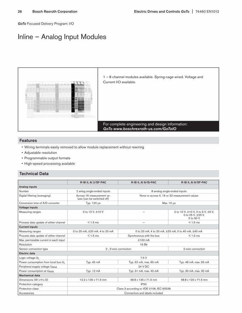
1 – 8 channel modules available. Spring-cage wired. Voltage and Current I/O available.
Inline – Analog Input Modules
GoTo Focused Delivery Program: I/O
Features• Wiring terminals easily removed to allow module replacement without rewiring
• Adjustable resolution
• Programmable output formats
• High-speed processing available
Technical Data
R-IB IL AI 2/SF-PAC R-IB IL AI 8/IS-PAC R-IB IL AI 8/SF-PAC
Analog inputs
Number 2 anlog single-ended inputs 8 analog single-ended inputs
Digital filtering (averaging) Across 16 measurement va-lues (can be switched off)
None or across 4, 16 or 32 measurement values
Conversion time of A/D converter Typ. 120 µs Max. 10 µs
Voltage inputs
Measuring ranges 0 to 10 V, ±10 V — 0 to 10 V, ±10 V, 0 to 5 V, ±5 V, 0 to 25 V, ±25 V,
0 to 50 V Process data update of either channel < 1.5 ms — < 1.5 ms
Current inputs
Measuring ranges 0 to 20 mA, ±20 mA, 4 to 20 mA 0 to 20 mA, 4 to 20 mA, ±20 mA, 0 to 40 mA, ±40 mA
Process data update of either channel < 1.5 ms Synchronous with the bus < 1.5 ms
Max. permissible current in each input ±100 mA
Resolution 16 Bit
Sensor connection type 2-, 3-wire connection 2-wire connection
Electric data
Logic voltage UL 7.5 V
Power consumption from local bus UL Typ. 45 mA Typ. 52 mA, max. 65 mA Typ. 48 mA, max. 55 mA
Peripheral supply voltage UANA 24 V DC
Power consumption at UANA Typ. 12 mA Typ. 31 mA, max. 40 mA Typ. 30 mA, max. 35 mA
Mechanical data
Dimensions (W x H x D) 12.2 x 135 x 71.5 mm 48.8 x 135 x 71.5 mm 48.8 x 120 x 71.5 mm
Protection category IP20
Protection class Class 3 according to VDE 0106, IEC 60536
Accessories Connectors and labels included
74460 EN1012 Electric Drives and Controls GoTo Bosch Rexroth Corporation 27
For complete engineering and design information: GoTo www.boschrexroth-us.com/GoToIO
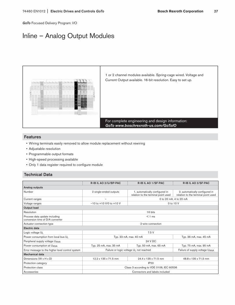
1 or 2 channel modules available. Spring-cage wired. Voltage and Current Output available. 16-bit resolution. Easy to set up.
Inline – Analog Output Modules
GoTo Focused Delivery Program: I/O
Features• Wiring terminals easily removed to allow module replacement without rewiring
• Adjustable resolution
• Programmable output formats
• High-speed processing available
• Only 1 data register required to configure module
Technical Data
R-IB IL AO 2/U/BP-PAC R-IB IL AO 1/SF-PAC R-IB IL AO 2/SF-PAC
Analog outputs
Number 2 single-ended outputs 1, automatically configured in relation to the terminal point used
2, automatically configured in relation to the terminal point used
Current ranges – 0 to 20 mA, 4 to 20 mA
Voltage ranges –10 to +10 V/0 to +10 V 0 to 10 V
Output load
Resolution 16 bits
Process data update including conversion time of D/A converter
< 1 ms
Actuator connection type 2-wire connection
Electric data
Logic voltage UL 7.5 V
Power consumption from local bus UL Typ. 33 mA, max. 40 mA Typ. 36 mA, max. 45 mA
Peripheral supply voltage UANA 24 V DC
Power consumption at UANA Typ. 25 mA, max. 35 mA Typ. 50 mA, max. 65 mA Typ. 75 mA, max. 95 mA
Error message to the higher level control system Failure or logic voltage UL not reached Failure of supply voltage UANA
Mechanical data
Dimensions (W x H x D) 12.2 x 135 x 71.5 mm 24.4 x 135 x 71.5 mm 48.8 x 135 x 71.5 mm
Protection category IP20
Protection class Class 3 according to VDE 0106, IEC 60536
Accessories Connectors and labels included
Electric Drives and Controls GoTo 74460 EN1012Bosch Rexroth Corporation28
For complete engineering and design information: GoTo www.boschrexroth-us.com/GoToIO
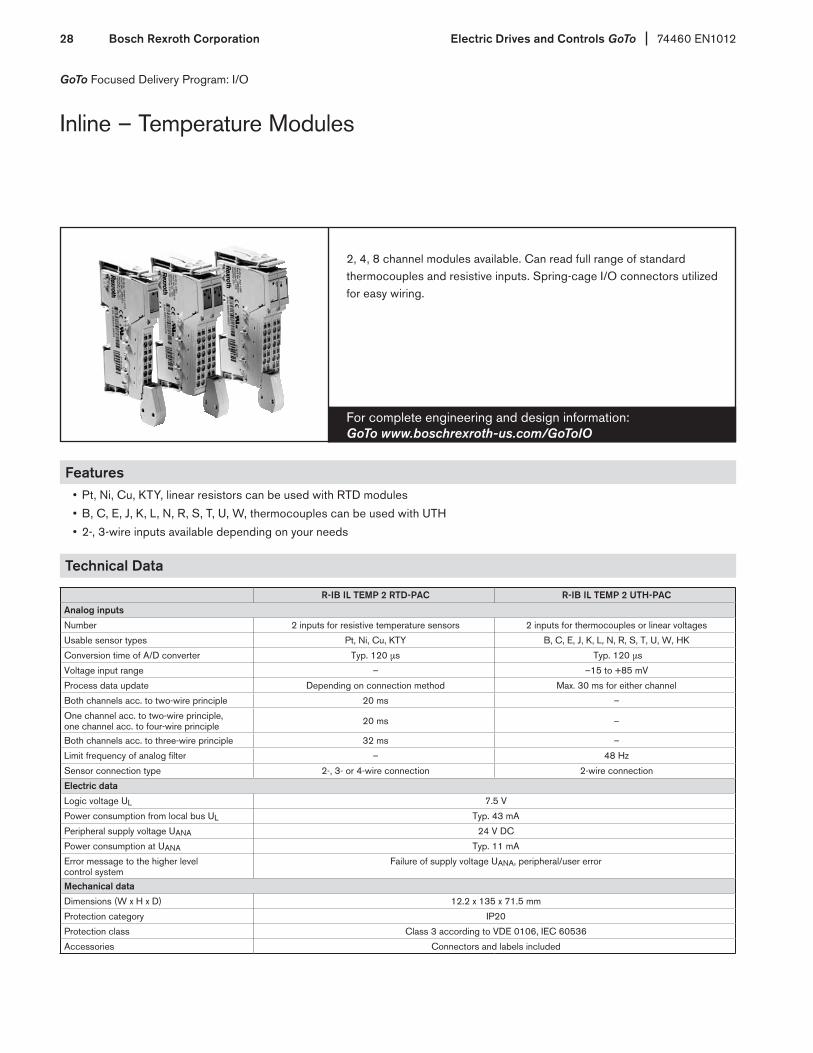
2, 4, 8 channel modules available. Can read full range of standard thermocouples and resistive inputs. Spring-cage I/O connectors utilized for easy wiring.
Inline – Temperature Modules
GoTo Focused Delivery Program: I/O
Features• Pt, Ni, Cu, KTY, linear resistors can be used with RTD modules
• B, C, E, J, K, L, N, R, S, T, U, W, thermocouples can be used with UTH
• 2-, 3-wire inputs available depending on your needs
Technical Data
R-IB IL TEMP 2 RTD-PAC R-IB IL TEMP 2 UTH-PAC
Analog inputs
Number 2 inputs for resistive temperature sensors 2 inputs for thermocouples or linear voltages
Usable sensor types Pt, Ni, Cu, KTY B, C, E, J, K, L, N, R, S, T, U, W, HK
Conversion time of A/D converter Typ. 120 µs Typ. 120 µs
Voltage input range – –15 to +85 mV
Process data update Depending on connection method Max. 30 ms for either channel
Both channels acc. to two-wire principle 20 ms –
One channel acc. to two-wire principle, one channel acc. to four-wire principle 20 ms –
Both channels acc. to three-wire principle 32 ms –
Limit frequency of analog filter – 48 Hz
Sensor connection type 2-, 3- or 4-wire connection 2-wire connection
Electric data
Logic voltage UL 7.5 V
Power consumption from local bus UL Typ. 43 mA
Peripheral supply voltage UANA 24 V DC
Power consumption at UANA Typ. 11 mA
Error message to the higher level control system
Failure of supply voltage UANA, peripheral/user error
Mechanical data
Dimensions (W x H x D) 12.2 x 135 x 71.5 mm
Protection category IP20
Protection class Class 3 according to VDE 0106, IEC 60536
Accessories Connectors and labels included
74460 EN1012 Electric Drives and Controls GoTo Bosch Rexroth Corporation 29
For complete engineering and design information: GoTo www.boschrexroth-us.com/GoToIO
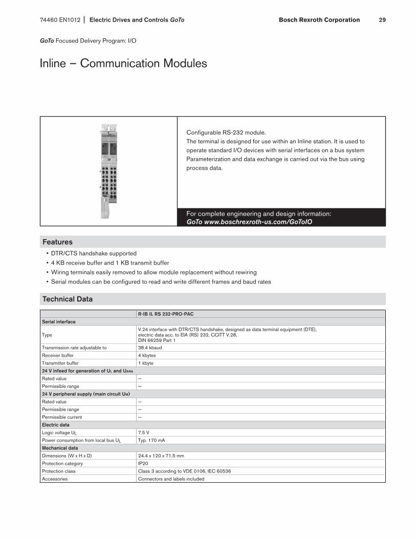
Configurable RS-232 module.The terminal is designed for use within an Inline station. It is used to operate standard I/O devices with serial interfaces on a bus systemParameterization and data exchange is carried out via the bus using process data.
Inline – Communication Modules
GoTo Focused Delivery Program: I/O
Features• DTR/CTS handshake supported
• 4 KB receive buffer and 1 KB transmit buffer
• Wiring terminals easily removed to allow module replacement without rewiring
• Serial modules can be configured to read and write different frames and baud rates
Technical Data
R-IB IL RS 232-PRO-PAC
Serial interface
Type V.24 interface with DTR/CTS handshake, designed as data terminal equipment (DTE), electric data acc. to EIA (RS) 232, CCITT V.28, DIN 66259 Part 1
Transmission rate adjustable to 38.4 kbaud
Receiver buffer 4 kbytes
Transmitter buffer 1 kbyte
24 V infeed for generation of UL and UANA
Rated value —
Permissible range —
24 V peripheral supply (main circuit UM)
Rated value —
Permissible range —
Permissible current —
Electric data
Logic voltage UL 7.5 V
Power consumption from local bus UL Typ. 170 mA
Mechanical data
Dimensions (W x H x D) 24.4 x 120 x 71.5 mm
Protection category IP20
Protection class Class 3 according to VDE 0106, IEC 60536
Accessories Connectors and labels included
Electric Drives and Controls GoTo 74460 EN1012Bosch Rexroth Corporation30
For complete engineering and design information: GoTo www.boschrexroth-us.com/GoToIO
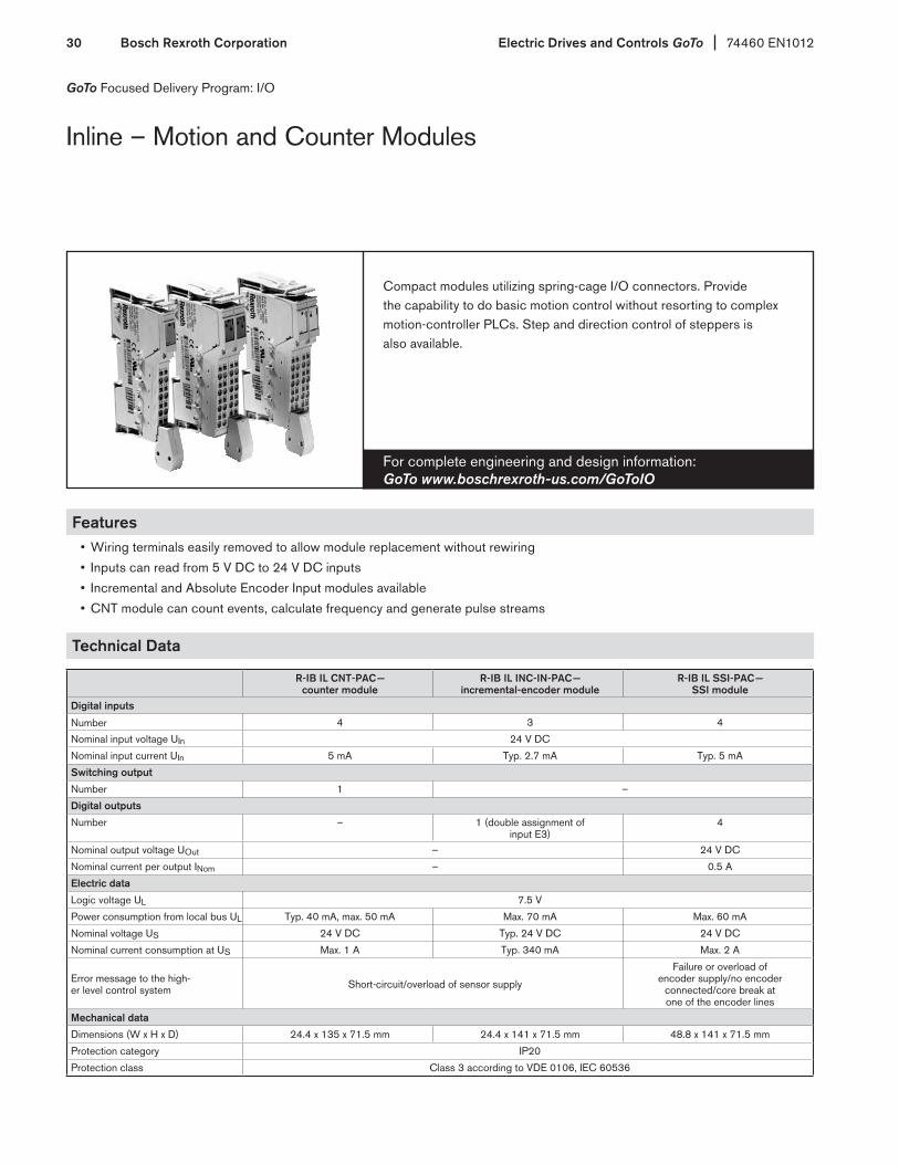
Compact modules utilizing spring-cage I/O connectors. Provide the capability to do basic motion control without resorting to complex motion-controller PLCs. Step and direction control of steppers is also available.
Inline – Motion and Counter Modules
GoTo Focused Delivery Program: I/O
Features• Wiring terminals easily removed to allow module replacement without rewiring
• Inputs can read from 5 V DC to 24 V DC inputs
• Incremental and Absolute Encoder Input modules available
• CNT module can count events, calculate frequency and generate pulse streams
Technical Data
R-IB IL CNT-PAC — counter module
R-IB IL INC-IN-PAC — incremental-encoder module
R-IB IL SSI-PAC — SSI module
Digital inputs
Number 4 3 4
Nominal input voltage UIn 24 V DC
Nominal input current UIn 5 mA Typ. 2.7 mA Typ. 5 mA
Switching output
Number 1 –
Digital outputs
Number – 1 (double assignment of input E3)
4
Nominal output voltage UOut – 24 V DC
Nominal current per output INom – 0.5 A
Electric data
Logic voltage UL 7.5 V
Power consumption from local bus UL Typ. 40 mA, max. 50 mA Max. 70 mA Max. 60 mA
Nominal voltage US 24 V DC Typ. 24 V DC 24 V DC
Nominal current consumption at US Max. 1 A Typ. 340 mA Max. 2 A
Error message to the high-er level control system Short-circuit/overload of sensor supply
Failure or overload of encoder supply/no encoder
connected/core break at one of the encoder lines
Mechanical data
Dimensions (W x H x D) 24.4 x 135 x 71.5 mm 24.4 x 141 x 71.5 mm 48.8 x 141 x 71.5 mm
Protection category IP20
Protection class Class 3 according to VDE 0106, IEC 60536

74460 EN1012 Electric Drives and Controls GoTo Bosch Rexroth Corporation 31
GoTo Focused Delivery Program: I/O
For complete engineering and design information: GoTo www.boschrexroth-us.com/GoToIO
Feed Module – For supplying IndraControl S67 components mounted on the machine with 24 V DC for expansion of the I/O system.
IndraControl S67 – Power Divider
Features• Allow for one 24V DC cable run out to the machine for I/O power distribution
• IP 67 rating for harsh machine environments
Technical Data
Power Divider S67-PWR-IN-M12Connection type M23 connectors, 6 polesSupply voltageLogic and sensor voltage ULS 24 V DC (–25 to +30%)Actuator Voltage UA 24 V DC (–25 to +30%)Supply currentLogic and sensor current ILS Typ. 4 mAActuator current IA Typ. 4 mASupply outputsNumber 6Connection type M12 connectors, A coded, 4 polesCurrent carrying capacity (connector) Max. 8 A (ULS: 4 A, UA: 4 A)Current carrying capacity (module) Max. 24 A (ULS: msx. 8 A, UA: max. 16 A)Short circuit protection NoElectrical isolationULS – UA 500 V DCAmbient conditionsPermissible temperature (operation) –25 to +80 °CPermissible relative humidity (operation) 5 to 95 %Permissible air pressure (operation) 795 to 1,080 hPaMechanical dataDimensions (W x H x D) 50 x 117 x 35 mmDimensional drawing Type 2Weight 240 gProtection class IP67 (NEMA 6&6P), DIN40050 (EN60529)Vibration resistance According to IEC 60068-2-6Shock resistance (temporary) According to IEC 60068-2-27LED indicatorsULS + UA – Supply status LED (green)LED indicators Non-latching

Electric Drives and Controls GoTo 74460 EN1012Bosch Rexroth Corporation32
GoTo Focused Delivery Program: I/O
For complete engineering and design information: GoTo www.boschrexroth-us.com/GoToIO
IP67 Fieldbus Coupler – Mounted on the machine for connecting local I/O modules to a higher-level fieldbus system.
IndraControl S67 – Bus Coupler
Features• 8 on board inputs included with the Profibus bus coupler
• Built in status light to troubleshoot module out on the machine
• Up to 64 I/O modules can be operated from a single Fieldbus coupler
Technical Data
Fieldbus coupler S67-PB-BK-DI8-M8Type PROFIBUS slaveConnection type M12 connectors, B coded, 5 polesTansmission speed 12 Mbit/s (automatic recognition) Transmission medium Copper cable Digital inputs Number 8Connection type M8 connectors, A coded, 3 polesSensor connection type 2-, 3-wire connectionInput filter ParametrizableInput characteristic Type 1, acc. to IEC 61131-2Signal voltage (0) –30 to +5 V DCSignal voltage (1) +11 to +30 V DCInput circuit High-side switchingInput voltage 24 V DC (–30 < UIN < +30 V DC) Input current Typ. 2.8 mACable length, unshielded ≤ 30 mModule supplyConnection type M12 connectors, A coded, 4 polesCurrent carrying capacity of supply connections Max. 8 A (ULS: 4 A, UA: 4 A) Logic and sensor voltage ULS 24 V DC (–25 to +30 %) Actuator voltage UA 24 V DC (–25 to +30 %) Logic and sensor current ILS Typ. 110 mA + sensor (max. 400 mA) Actuator current IA 5 mAProtection Reverse voltage protection for ULS + UA short circuit protection for sensor supplySystem busNumber of expandable modules 63Connection type M12 connectors, B coded, 5 poles, shieldedElectrical isolationChannel – Channel NoULS, UA, system bus, fieldbus 500 V DC each
continued on next page
74460 EN1012 Electric Drives and Controls GoTo Bosch Rexroth Corporation 33
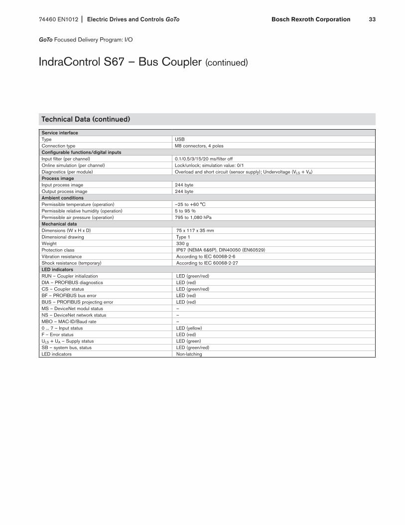
GoTo Focused Delivery Program: I/O
IndraControl S67 – Bus Coupler (continued)
Technical Data (continued)
Service interfaceType USBConnection type M8 connectors, 4 polesConfigurable functions/digital inputsInput filter (per channel) 0.1/0.5/3/15/20 ms/filter offOnline simulation (per channel) Lock/unlock; simulation value: 0/1Diagnostics (per module) Overload and short circuit (sensor supply); Undervoltage (VLS + VA) Process imageInput process image 244 byteOutput process image 244 byteAmbient conditions Permissible temperature (operation) –25 to +60 °C Permissible relative humidity (operation) 5 to 95 %Permissible air pressure (operation) 795 to 1,080 hPaMechanical data Dimensions (W x H x D) 75 x 117 x 35 mm Dimensional drawing Type 1 Weight 330 g Protection class IP67 (NEMA 6&6P), DIN40050 (EN60529) Vibration resistance According to IEC 60068-2-6 Shock resistance (temporary) According to IEC 60068-2-27 LED indicators RUN – Coupler initialization LED (green/red) DIA – PROFIBUS diagnostics LED (red) CS – Coupler status LED (green/red) BF – PROFIBUS bus error LED (red) BUS – PROFIBUS projecting error LED (red) MS – DeviceNet modul status – NS – DeviceNet network status – MBO – MAC-ID/Baud rate – 0 ... 7 – Input status LED (yellow) F – Error status LED (red) ULS + UA – Supply status LED (green) SB – system bus, status LED (green/red) LED indicators Non-latching

Electric Drives and Controls GoTo 74460 EN1012Bosch Rexroth Corporation34
GoTo Focused Delivery Program: I/O
For complete engineering and design information: GoTo www.boschrexroth-us.com/GoToIO
IP67 Digital Input Modules – Mounted on the machine for acquiring digital signals, e.g. buttons limit or proximity switches.
IndraControl S67 – Digital Input Modules
Features• Expandable to 500 m per I/O station
• M12 and M8 connection technology in compact housing design
Digital Inputs
Technical data S67-DI8-M8 S67-DI8-M12Digital inputs Number 8 4Connection type M8 connectors, A coded, 3 poles M12 connectors, A coded, 5 polesSensor connection type 2-, 3-wire connection 2-, 3-wire connectionInput filter Parametrizable ParametrizableInput characteristic Type 2, acc. to IEC 61131-2 Type 2, acc. to IEC 61131-2Signal voltage (0) –30 to +5 V DC –30 to +5 V DC Signal voltage (1) +11 to +30 V DC +11 to +30 V DC Input circuit High-side switching High-side switchingInput voltage 24 VDC (–30 V DC < UIN < +30 V DC) 24 VDC (–30 V DC < UIN < +30 V DC) Input current Typ. 7.3 mA Typ. 7.3 mACable length, unshielded ≤ 30 m ≤ 30 mModule supplyConnection type M12 connectors, A coded, 4 poles M12 connectors, A coded, 4 polesCurrent carrying capacity of supply connections Max. 8 A (ULS: 4 A, UA: 4 A) Max. 8 A (ULS: 4 A, UA: 4 A) Logic and sensor voltage ULS 24 V DC 24 V DC Actuator voltage UA 24 V DC 24 V DC Logic and sensor current ILS Typ. 40 mA + sensor (max. 400 mA) Typ. 40 mA + sensor (max. 400 mA) Actuator current IA 5 mA 5 mAProtection Reverse voltage protection for ULS + UA short
circuit protection for sensor supplyReverse voltage protection for ULS + UA short
circuit protection for sensor supplySystem busConnection type M12 connectors, B coded, 5 poles, shielded M12 connectors, B coded, 5 poles, shieldedElectrical isolationChannel – Channel No NoULS, UA, system bus 500 V DC each 500 V DC each
continued on next page

74460 EN1012 Electric Drives and Controls GoTo Bosch Rexroth Corporation 35
GoTo Focused Delivery Program: I/O
IndraControl S67 – Digital Input Modules (continued)
Digital Inputs (continued)
Configurable functions Input filter (per channel) 0.1/0.5/3/15/20 ms/filter off 0.1/0.5/3/15/20 ms/filter offOnline simulation (per channel) Lock/unlock; simulation value: 0/1 Lock/unlock; simulation value: 0/1Diagnostics (per module) Overload and short circuit (sensor supply),
Undervoltage (ULS + UA)Overload and short circuit (sensor supply),
Undervoltage (ULS + UA)Process imageProcess data width 1 byte data + status 1 byte data + statusAmbient conditions Permissible temperature (operation) –25 to +60 °C –25 to +60 °C Permissible relative humidity (operation) 5 to 95 % 5 to 95 %Permissible air pressure (operation) 795 to 1,080 hPa 795 to 1,080 hPaMechanical data Dimensions (W x H x D) 50 x 117 x 35 mm 50 x 117 x 35 mmDimensional drawing Type 2 Type 2Weight 230 g 230 gProtection class IP67 (NEMA 6&6P), DIN40050 (EN60529) IP67 (NEMA 6&6P), DIN40050 (EN60529)Vibration resistance According to IEC 60068-2-6 According to IEC 60068-2-6Shock resistance (temporary) According to IEC 60068-2-27 According to IEC 60068-2-27LED indicators0 ... 7 – Input status LED (yellow) LED (yellow)F – Error status LED (red) LED (red)ULS + UA – Supply status LED (green) LED (green)SB – system bus, status LED (green/red) LED (green/red) LED indicators Non-latching Non-latching
Electric Drives and Controls GoTo 74460 EN1012Bosch Rexroth Corporation36
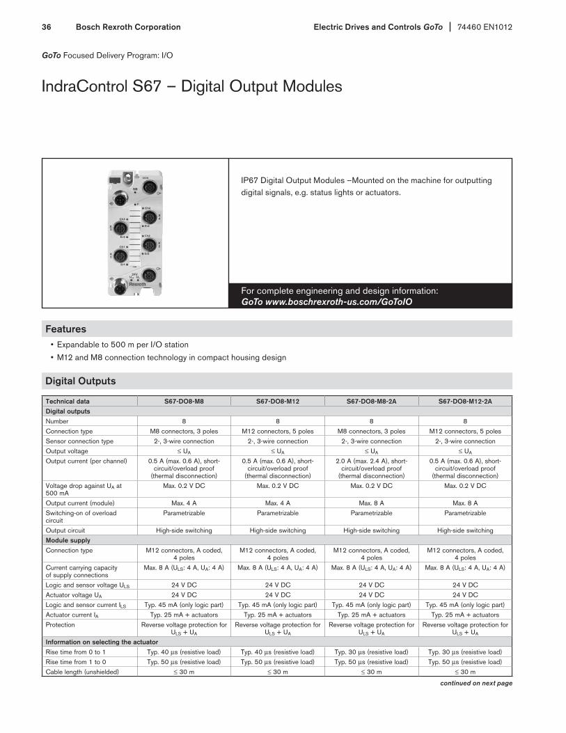
For complete engineering and design information: GoTo www.boschrexroth-us.com/GoToIO
IP67 Digital Output Modules –Mounted on the machine for outputting digital signals, e.g. status lights or actuators.
GoTo Focused Delivery Program: I/O
IndraControl S67 – Digital Output Modules
Features• Expandable to 500 m per I/O station
• M12 and M8 connection technology in compact housing design
Digital Outputs
Technical data S67-DO8-M8 S67-DO8-M12 S67-DO8-M8-2A S67-DO8-M12-2ADigital outputsNumber 8 8 8 8Connection type M8 connectors, 3 poles M12 connectors, 5 poles M8 connectors, 3 poles M12 connectors, 5 polesSensor connection type 2-, 3-wire connection 2-, 3-wire connection 2-, 3-wire connection 2-, 3-wire connectionOutput voltage ≤ UA ≤ UA ≤ UA ≤ UA
Output current (per channel) 0.5 A (max. 0.6 A), short-circuit/overload proof
(thermal disconnection)
0.5 A (max. 0.6 A), short-circuit/overload proof
(thermal disconnection)
2.0 A (max. 2.4 A), short-circuit/overload proof
(thermal disconnection)
0.5 A (max. 0.6 A), short-circuit/overload proof
(thermal disconnection)Voltage drop against UA at 500 mA
Max. 0.2 V DC Max. 0.2 V DC Max. 0.2 V DC Max. 0.2 V DC
Output current (module) Max. 4 A Max. 4 A Max. 8 A Max. 8 A Switching-on of overload circuit
Parametrizable Parametrizable Parametrizable Parametrizable
Output circuit High-side switching High-side switching High-side switching High-side switchingModule supplyConnection type M12 connectors, A coded,
4 polesM12 connectors, A coded,
4 polesM12 connectors, A coded,
4 polesM12 connectors, A coded,
4 polesCurrent carrying capacity of supply connections
Max. 8 A (ULS: 4 A, UA: 4 A) Max. 8 A (ULS: 4 A, UA: 4 A) Max. 8 A (ULS: 4 A, UA: 4 A) Max. 8 A (ULS: 4 A, UA: 4 A)
Logic and sensor voltage ULS 24 V DC 24 V DC 24 V DC 24 V DCActuator voltage UA 24 V DC 24 V DC 24 V DC 24 V DCLogic and sensor current ILS Typ. 45 mA (only logic part) Typ. 45 mA (only logic part) Typ. 45 mA (only logic part) Typ. 45 mA (only logic part) Actuator current IA Typ. 25 mA + actuators Typ. 25 mA + actuators Typ. 25 mA + actuators Typ. 25 mA + actuatorsProtection Reverse voltage protection for
ULS + UA
Reverse voltage protection for ULS + UA
Reverse voltage protection for ULS + UA
Reverse voltage protection for ULS + UA
Information on selecting the actuatorRise time from 0 to 1 Typ. 40 µs (resistive load) Typ. 40 µs (resistive load) Typ. 30 µs (resistive load) Typ. 30 µs (resistive load)Rise time from 1 to 0 Typ. 50 µs (resistive load) Typ. 50 µs (resistive load) Typ. 50 µs (resistive load) Typ. 50 µs (resistive load) Cable length (unshielded) ≤ 30 m ≤ 30 m ≤ 30 m ≤ 30 m
continued on next page
74460 EN1012 Electric Drives and Controls GoTo Bosch Rexroth Corporation 37
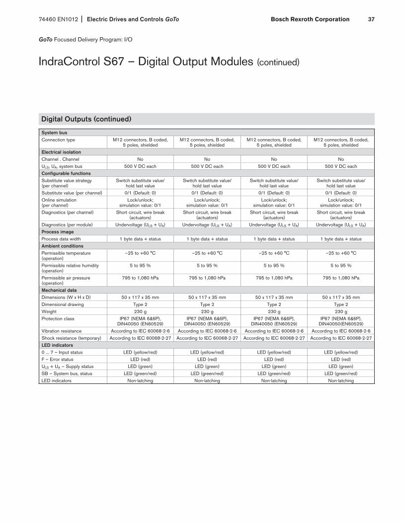
GoTo Focused Delivery Program: I/O
IndraControl S67 – Digital Output Modules (continued)
Digital Outputs (continued)
System busConnection type M12 connectors, B coded,
5 poles, shieldedM12 connectors, B coded,
5 poles, shieldedM12 connectors, B coded,
5 poles, shieldedM12 connectors, B coded,
5 poles, shieldedElectrical isolationChannel . Channel No No No NoULS, UA, system bus 500 V DC each 500 V DC each 500 V DC each 500 V DC eachConfigurable functions Substitute value strategy (per channel)
Switch substitute value/ hold last value
Switch substitute value/ hold last value
Switch substitute value/ hold last value
Switch substitute value/ hold last value
Substitute value (per channel) 0/1 (Default: 0) 0/1 (Default: 0) 0/1 (Default: 0) 0/1 (Default: 0) Online simulation (per channel)
Lock/unlock; simulation value: 0/1
Lock/unlock; simulation value: 0/1
Lock/unlock; simulation value: 0/1
Lock/unlock; simulation value: 0/1
Diagnostics (per channel) Short circuit, wire break (actuators)
Short circuit, wire break (actuators)
Short circuit, wire break (actuators)
Short circuit, wire break (actuators)
Diagnostics (per module) Undervoltage (ULS + UA) Undervoltage (ULS + UA) Undervoltage (ULS + UA) Undervoltage (ULS + UA) Process imageProcess data width 1 byte data + status 1 byte data + status 1 byte data + status 1 byte data + statusAmbient conditions Permissible temperature (operation)
–25 to +60 °C –25 to +60 °C –25 to +60 °C –25 to +60 °C
Permissible relative humidity (operation)
5 to 95 % 5 to 95 % 5 to 95 % 5 to 95 %
Permissible air pressure (operation)
795 to 1,080 hPa 795 to 1,080 hPa 795 to 1,080 hPa 795 to 1,080 hPa
Mechanical data Dimensions (W x H x D) 50 x 117 x 35 mm 50 x 117 x 35 mm 50 x 117 x 35 mm 50 x 117 x 35 mm Dimensional drawing Type 2 Type 2 Type 2 Type 2 Weight 230 g 230 g 230 g 230 g Protection class IP67 (NEMA 6&6P),
DIN40050 (EN60529) IP67 (NEMA 6&6P),
DIN40050 (EN60529) IP67 (NEMA 6&6P),
DIN40050 (EN60529) IP67 (NEMA 6&6P),
DIN40050(EN60529) Vibration resistance According to IEC 60068-2-6 According to IEC 60068-2-6 According to IEC 60068-2-6 According to IEC 60068-2-6 Shock resistance (temporary) According to IEC 60068-2-27 According to IEC 60068-2-27 According to IEC 60068-2-27 According to IEC 60068-2-27 LED indicators 0 ... 7 – Input status LED (yellow/red) LED (yellow/red) LED (yellow/red) LED (yellow/red) F – Error status LED (red) LED (red) LED (red) LED (red) ULS + UA – Supply status LED (green) LED (green) LED (green) LED (green) SB – System bus, status LED (green/red) LED (green/red) LED (green/red) LED (green/red) LED indicators Non-latching Non-latching Non-latching Non-latching
Electric Drives and Controls GoTo 74460 EN1012Bosch Rexroth Corporation38
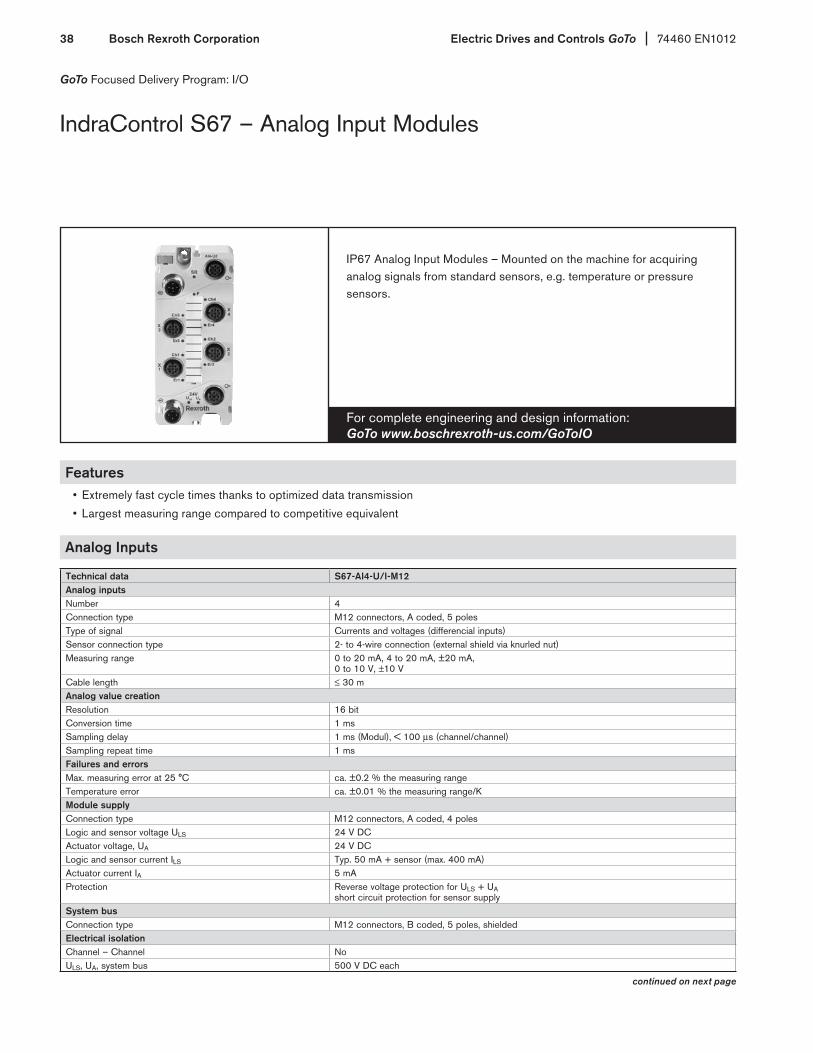
GoTo Focused Delivery Program: I/O
For complete engineering and design information: GoTo www.boschrexroth-us.com/GoToIO
IP67 Analog Input Modules – Mounted on the machine for acquiring analog signals from standard sensors, e.g. temperature or pressure sensors.
IndraControl S67 – Analog Input Modules
Features• Extremely fast cycle times thanks to optimized data transmission
• Largest measuring range compared to competitive equivalent
Analog Inputs
Technical data S67-AI4-U/I-M12Analog inputsNumber 4Connection type M12 connectors, A coded, 5 polesType of signal Currents and voltages (differencial inputs)Sensor connection type 2- to 4-wire connection (external shield via knurled nut)Measuring range 0 to 20 mA, 4 to 20 mA, ±20 mA,
0 to 10 V, ±10 VCable length ≤ 30 mAnalog value creationResolution 16 bitConversion time 1 msSampling delay 1 ms (Modul), < 100 µs (channel/channel) Sampling repeat time 1 msFailures and errorsMax. measuring error at 25 °C ca. ±0.2 % the measuring rangeTemperature error ca. ±0.01 % the measuring range/KModule supplyConnection type M12 connectors, A coded, 4 polesLogic and sensor voltage ULS 24 V DCActuator voltage, UA 24 V DCLogic and sensor current ILS Typ. 50 mA + sensor (max. 400 mA)Actuator current IA 5 mAProtection Reverse voltage protection for ULS + UA
short circuit protection for sensor supplySystem bus Connection type M12 connectors, B coded, 5 poles, shieldedElectrical isolationChannel – Channel NoULS, UA, system bus 500 V DC each
continued on next page
74460 EN1012 Electric Drives and Controls GoTo Bosch Rexroth Corporation 39
GoTo Focused Delivery Program: I/O
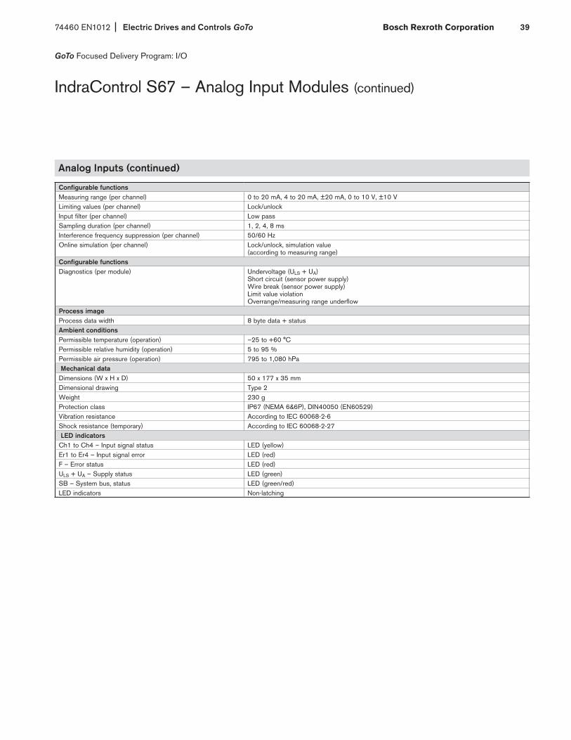
IndraControl S67 – Analog Input Modules (continued)
Analog Inputs (continued)
Configurable functions Measuring range (per channel) 0 to 20 mA, 4 to 20 mA, ±20 mA, 0 to 10 V, ±10 VLimiting values (per channel) Lock/unlockInput filter (per channel) Low passSampling duration (per channel) 1, 2, 4, 8 msInterference frequency suppression (per channel) 50/60 HzOnline simulation (per channel) Lock/unlock, simulation value
(according to measuring range)Configurable functions Diagnostics (per module) Undervoltage (ULS + UA)
Short circuit (sensor power supply) Wire break (sensor power supply) Limit value violation Overrange/measuring range underflow
Process image Process data width 8 byte data + status Ambient conditions Permissible temperature (operation) –25 to +60 °C Permissible relative humidity (operation) 5 to 95 % Permissible air pressure (operation) 795 to 1,080 hPa Mechanical dataDimensions (W x H x D) 50 x 177 x 35 mm Dimensional drawing Type 2 Weight 230 g Protection class IP67 (NEMA 6&6P), DIN40050 (EN60529) Vibration resistance According to IEC 60068-2-6 Shock resistance (temporary) According to IEC 60068-2-27 LED indicators Ch1 to Ch4 – Input signal status LED (yellow) Er1 to Er4 – Input signal error LED (red) F – Error status LED (red) ULS + UA – Supply status LED (green) SB – System bus, status LED (green/red) LED indicators Non-latching

Electric Drives and Controls GoTo 74460 EN1012Bosch Rexroth Corporation40
GoTo Focused Delivery Program: I/O
IndraControl S67 – Analog Output Modules
For complete engineering and design information: GoTo www.boschrexroth-us.com/GoToIO
IP67 Analog Output Modules – Mounted on the machine for outputting analog signals for external controls.
Features• Online simulation
• Event driven signal substitution
• Largest measuring range compared to competition
Analog Outputs
Technical data S67-AO4-U/I-M12Analog outputsNumber 4Connection type M12 connectors, A coded, 5 polesType of signal Currents and voltages Sensor connection type 2- to 4-wire connection (external shield via knurled nut)Measuring range 0 to 20 mA, 4 to 20 mA, ±20 mA, 0 to 10 V, ±10 VOutput load (load impedance) ≤ 500 Ω (current) ; ≥ 5 kΩ (voltage) Maximum capacitive load (at voltage outputs) 10 nFMaximum inductive load (at current outputs) 1 mHCable length ≤ 30 mAnalog value creationResolution 15 bit (unipolar), 16 bit (bipolar)Monotony YesCycle time Typ. 1 msRecovery time for resistive, inductive and capacitive loads Typ. 1 msFailures and errorsMax. measuring error at 25 °C ≤ ±0.2 % the measuring rangeOvershooting Typ. ±0.05 % the measuring rangeOutput ripple Typ. ±0.02 % the measuring rangeCrosstalk between the channels at DC voltage and AC voltage 50 Hz and 60 Hz
–90 dB
Short circuit protection ElectronicNominal output current Max. 1 A
continued on next page

74460 EN1012 Electric Drives and Controls GoTo Bosch Rexroth Corporation 41
GoTo Focused Delivery Program: I/O
IndraControl S67 – Analog Output Modules (continued)
Analog Outputs (continued)
Module supplyConnection type M12 connectors, A coded, 4 polesLogic and sensor voltage ULS 24 V DCActuator voltage UA 24 V DCLogic and sensor current ILS Typ. 28 mA (only logic part) Actuator current IA 34 mA + actuatorsProtection Reverse voltage protection for ULS + UA, overload and short circuit protection for sensor supplySystem busConnection type M12 connectors, B coded, 5 poles, shieldedElectrical isolationChannel . Channel NoULS, UA, system bus 500 VDC eachConfigurable functions Measuring range (per channel) 0 to 20 mA, 4 to 20 mA, ±20 mA, 0 to 10 V, ±10 VSubstitute value strategy (per channel) Switch substitute value/hold last value Substitute value (per channel) 0 mA or 0 V/substitute value according to measuring range (Default: 0 mA or 0 V)Online simulation (per channel) Lock/unlock, simulation value (according to measuring range)Diagnostics (per module) Short circuit (actuator supply), wire break (current), undervoltage (ULS + UA)Process imageProcess data width 8 byte data + statusAmbient conditions Permissible temperature (operation) –25 to +60 °C Permissible relative humidity (operation) 5 to 95 % Permissible air pressure (operation) 795 to 1,080 hPa Mechanical data Dimensions (W x H x D) 50 x 117 x 35 mm Dimensional drawing Type 2 Weight 230 g Protection class IP67 (NEMA 6&6P), DIN40050 (EN60529) Vibration resistance According to IEC 60068-2-6 Shock resistance (temporary) According to IEC 60068-2-27 LED indicators Ch1 to Ch4 – Input signal status LED (yellow) Er1 to Er4 – Input signal error LED (red) F – Error status LED (red) ULS + UA – Supply status LED (green) SB – System bus, status LED (green/red) LED indicators Non-latching

Electric Drives and Controls GoTo 74460 EN1012Bosch Rexroth Corporation42
GoTo Focused Delivery Program: I/O
IndraControl S67 – Temperature Modules
For complete engineering and design information: GoTo www.boschrexroth-us.com/GoToIO
IP67 RTD Signal Input Modules – Mounted on the machine for analog signals from temperature sensors.
Features• Configurable diagnostic threshold• Online simulation• Largest measuring range compared to competition
Temperature Modules
Technical data S67-AI4-RTD-M12Analog inputsNumber 4Connection type M12 connectors, A coded, 5 polesType of signal Resistance thermometers, resistors, potentiometersSensor connection type 2- to 4-wire connection (external shield via knurled nut)Signal measuring range Resistance thermometer: PT100, PT200, PT500, PT1000,
NI100, NI120, NI1000; Resistors: 1 kΩ and 4 kΩ; Potentiometer: 0 to 100 % setting angle (for 1.25 kΩ and 4 kΩ); Free characteristics: PT 3000, NTC etc.
Temperature range PT: –200 to +850 °C, NI: –60 to +250 °CCable length ≤ 30 mAnalog value creationResolution 16 bitInput filter 16.7 Hz, 33 Hz, 50 Hz, 60 Hz, 120 Hz, 250 Hz, 500 HzFailures and errorsMax. measuring error at 25 °C ±0.1 % the measuring rangeTemperature error ±0.001 % the measuring range/KModule supplyConnection type M12 connectors, A coded, 4 polesLogic and sensor voltage ULS 24 V DCActuator voltage, UA 24 V DCLogic and sensor current ILS Typ. 40 mA + sensor (max. 400 mA)Actuator current IA 5 mAProtection Reverse voltage protection for ULS + UA
short circuit protection for sensor supplySystem bus Connection type M12 connectors, B coded, 5 poles, shieldedElectrical isolationChannel – Channel NoULS, UA, system bus 500 V DC each
continued on next page
74460 EN1012 Electric Drives and Controls GoTo Bosch Rexroth Corporation 43
GoTo Focused Delivery Program: I/O
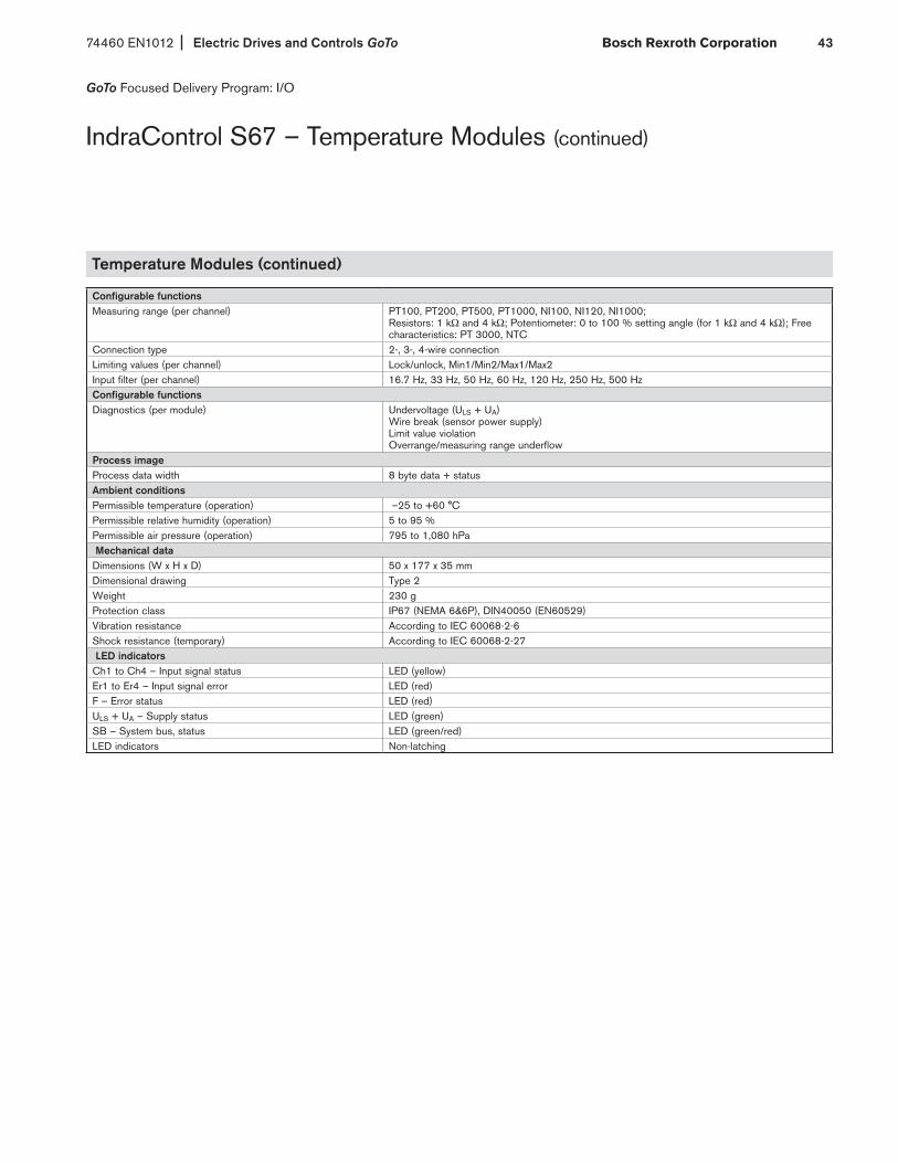
IndraControl S67 – Temperature Modules (continued)
Temperature Modules (continued)
Configurable functions Measuring range (per channel) PT100, PT200, PT500, PT1000, NI100, NI120, NI1000;
Resistors: 1 kΩ and 4 kΩ; Potentiometer: 0 to 100 % setting angle (for 1 kΩ and 4 kΩ); Free characteristics: PT 3000, NTC
Connection type 2-, 3-, 4-wire connectionLimiting values (per channel) Lock/unlock, Min1/Min2/Max1/Max2Input filter (per channel) 16.7 Hz, 33 Hz, 50 Hz, 60 Hz, 120 Hz, 250 Hz, 500 HzConfigurable functions Diagnostics (per module) Undervoltage (ULS + UA)
Wire break (sensor power supply) Limit value violation Overrange/measuring range underflow
Process image Process data width 8 byte data + status Ambient conditions Permissible temperature (operation) –25 to +60 °C Permissible relative humidity (operation) 5 to 95 % Permissible air pressure (operation) 795 to 1,080 hPa Mechanical dataDimensions (W x H x D) 50 x 177 x 35 mm Dimensional drawing Type 2 Weight 230 g Protection class IP67 (NEMA 6&6P), DIN40050 (EN60529) Vibration resistance According to IEC 60068-2-6 Shock resistance (temporary) According to IEC 60068-2-27 LED indicators Ch1 to Ch4 – Input signal status LED (yellow) Er1 to Er4 – Input signal error LED (red) F – Error status LED (red) ULS + UA – Supply status LED (green) SB – System bus, status LED (green/red) LED indicators Non-latching
Electric Drives and Controls GoTo 74460 EN1012Bosch Rexroth Corporation44
GoTo Focused Delivery Program: I/O
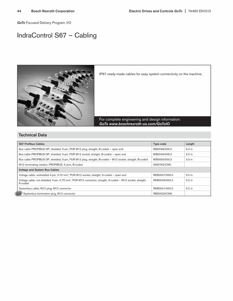
IndraControl S67 – Cabling
For complete engineering and design information: GoTo www.boschrexroth-us.com/GoToIO
IP67 ready-made cables for easy system connectivity on the machine.
Technical Data
S67 Profibus Cables Type code Length
Bus cable PROFIBUS DP, shielded, 5-pin, PUR M12 plug, straight, B-coded – open end IKB0048/005.0 5.0 m
Bus cable PROFIBUS DP, shielded, 5-pin, PUR M12 socket, straight, B-coded – open end IKB0049/005.0 5.0 m
Bus cable PROFIBUS DP, shielded, 5-pin, PUR M12 plug, straight, B-coded – M12 socket, straight, B-coded IKB0050/000.3 0.3 m
M12 terminating resistor, PROFIBUS, 5 pins, B-coded INS0762/CNN
Voltage and System Bus Cables
Voltage cable, unshielded 4-pin, 0.75 mm2, PUR M12 socket, straight, A-coded – open end RKB0047/005.0 5.0 m
Voltage cable, not shielded, 4-pin, 0.75 mm2, PUR M12 connector, straight, A-coded – M12 socket, straight, A-coded
RKB0046/000.2 0.2 m
Systembus cable, M12 plug, M12 connector RKB0041/000.2 0.2 m
Systembus termination plug, M12 connector RBS0020/CNN

74460 EN1012 Electric Drives and Controls GoTo Bosch Rexroth Corporation 45
For complete engineering and design information: GoTo www.boschrexroth-us.com/GoToHMI
Operator Terminals with small footprints to save on panel space. Can connect to a number of 3rd party products. Recipes and other powerful capabilities available.
Standard HMI
GoTo Focused Delivery Program: HMI
Features• Pushbutton and Touchscreen available
• Color and Greyscale available
• All terminals have Ethernet and USB ports
Technical Data
VCP 02 VCP 05 VCP 08 VCP 11 VCP 25 VCP 35
Display
FSTN FSTN-Touch STN-color-Touch TFT-Touch
5 grey tones 5 grey tones 125 colors 65,535 colors
3'' 3'' 3.8'' 3.8" 5.7'' 10.4''
Resolution 160 x 80 160 x 80 320 x 240 320 x 240 320 x 240, 1/4 VGA 640 x 480
Keyboard/touch Foil keys Touchscreen Touchscreen Touchscreen
Application memory 3 MB
Flash memory 16 MB
Slot for expansions 1
Line voltage 24 V DC
Interfaces* 1 x Ethernet TCP/IP, 2 x USB host
Front protection degree IP65
Dimensions (W x H x D) 144 x 96 x 58 mm 120 x 168 x 55 mm 155 x 205 x 55 mm 130 x 96 x 55 mm 203 x 147 x 66 mm 328 x 249 x 60 mm
*Additional communication options available, but not covered by GoTo program

Electric Drives and Controls GoTo 74460 EN1012Bosch Rexroth Corporation46
For complete engineering and design information: GoTo www.boschrexroth-us.com/GoToHMI
Powerful HMIs with great networking and 3rd party connectivity. Recipes, trending and other MES-like functionality available and easily implemented.
WinCE-based HMI
GoTo Focused Delivery Program: HMI
Features• Touchscreens
• Mulitple ports including USB, Ethernet, Serial and Profibus available onboard
• WinCE platform allows for connection to any product that supports OPC
Technical Data
VEP 30.4 VEP 40.4 VEP 50.4
Display 8.4'' – TFT 12.1'' – TFT 15'' – TFT
Resolution 800 x 600, SVGA 800 x 600, SVGA 1,024 x 768, XGA
Touchscreen Yes
Processor Intel Atom Prozessor 1,1 GHz.
RAM 1 GB
Compact flash 2 CF-Sockel, Standard 1 GB CF-Card , or optional 4 GB CF-Card
Module slots —
USB 3 (1 x Front)
Ethernet TCP/IP 1
Supply voltage 24 V DC
Operating system Windows CE 6.0.NET
Approvals CE/UL/CSA
Front protection degree IP65
Dimensions (W x H x D) 296 x 200 x 53 mm 350 x 290 x 51 mm 407 x 370 x 53 mm
Firmware
FWA-VEP*04-CWN-10VRS-D0-A* Windows CE 6.0.NET and WinStudio 7 Lite Runtime License
Software
SWS-WINSTU-RUN-07VRS-D0-WCE1K5 WinStudio 7 Runtime, single license 1,500 tags

74460 EN1012 Electric Drives and Controls GoTo Bosch Rexroth Corporation 47
For complete engineering and design information: GoTo www.boschrexroth-us.com/GoToSoftware
IndraWorks – a complete software suite can program HMIs, PLCs, drives and I/O systems in one IEC61131-3 environment.
IndraWorks
GoTo Focused Delivery Program: Software
FeaturesRexroth IndraWorks allows you to solve all tasks in a uniform and in tuitive software environment — from project planning and programming to visualization and diagnostics.
The uniform engineering framework IndraWorks is consistently available for all systems from the Rexroth Automation House. You, as a user, profit from the fast and transparent access to all functions and system data of the automation components. The standard ized tools and interfaces help you to solve all engineering tasks centrally with a single piece of software.
Your benefits:• Available for all systems and solutions from the Rexroth Automation House• Integrated framework for all engineering tasks• Consistent operating environment for project planning, programming, visualization and diagnostics• Central project management with intuitive system navigation• Intelligent operation with wizard support• Comprehensive online help• Uniform programming according to the PLC standard IEC 61131-3• PLCopen-conforming function block and technology libraries• Standardized interfaces for communication• Transparent access to all system components• Integrated FDT/DTM interface for integration of the DTM of third party manufacturers• Software programs all Bosch Rexroth PLCs and VEP HMIs• Optional IndraWorks Tool CamBuilder for IndraMotion available

Electric Drives and Controls GoTo 74460 EN1012Bosch Rexroth Corporation48
GoTo Focused Delivery Program: Software
VI-Composer
VI-Composer — efficient programming of your application in a convenient development environment.
For complete engineering and design information: GoTo www.boschrexroth-us.com/GoToSoftware
FeaturesVI-Composer is an easy but powerful project development tool for the visualization and parameterization of system-related data of the IndraControl VCP and VCH devices. In this convenient development environment, you can efficiently create your individual application, based on the usual Windows look-and-feel. The programming result can then be used on the various IndraControl VCP and VCH devices as often as desired.
The fully graphical VI-Composer software allows you to develop projects for IndraControl VCP and VCH devices according to the WYSIWYG (What You See Is What You Get) principle: text, variables and graphics are immediately represented just as they will be displayed by the IndraControl VCP and VCH devices. Predefined masks and comprehensive graphics libraries with numerous industry-compatible screen objects facilitate the creation of your applications. Based on Windows-conforming operation, you describe all variables depending on the particular control, whereas masks, graphics, re cipes and the like can be created independently of any control. VI-Composer provides direct access to the IndraWorks database and, thus, to all variables of the controls and drives. The performance is completed by comprehensive help functions. The VCP HMIs are programmed via the VI-Composer.
Your benefits:• Language management of the application with up to 16 languages• Messaging and recording system• Font editor for creating your own character sets• Easy graphics incorporation via OLE• Direct access to all control and drive variables• Project and firmware download for reloadable functions• Integrated creation of documenta tion and online help• Predefined masks, curves and bar graphs• Definition of free menu structures• Screen elements: texts, variables, graphics, switches,
buttons, drop-down list boxes, tables, etc.
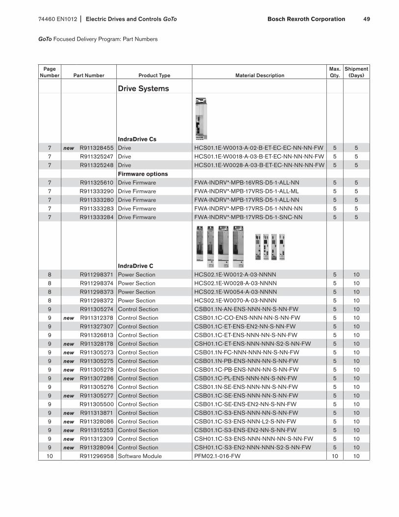
74460 EN1012 Electric Drives and Controls GoTo Bosch Rexroth Corporation 49
GoTo Focused Delivery Program: Part Numbers
Page Number Part Number Product Type Material Description
Max. Qty.
Shipment (Days)
Drive Systems
IndraDrive Cs7 new R911328455 Drive HCS01.1E-W0013-A-02-B-ET-EC-EC-NN-NN-FW 5 57 R911325247 Drive HCS01.1E-W0018-A-03-B-ET-EC-NN-NN-NN-FW 5 57 R911325248 Drive HCS01.1E-W0028-A-03-B-ET-EC-NN-NN-NN-FW 5 5
Firmware options7 R911325610 Drive Firmware FWA-INDRV*-MPB-16VRS-D5-1-ALL-NN 5 57 R911333290 Drive Firmware FWA-INDRV*-MPB-17VRS-D5-1-ALL-ML 5 57 R911333280 Drive Firmware FWA-INDRV*-MPB-17VRS-D5-1-ALL-NN 5 57 R911333283 Drive Firmware FWA-INDRV*-MPB-17VRS-D5-1-NNN-NN 5 57 R911333284 Drive Firmware FWA-INDRV*-MPB-17VRS-D5-1-SNC-NN 5 5
IndraDrive C 8 R911298371 Power Section HCS02.1E-W0012-A-03-NNNN 5 108 R911298374 Power Section HCS02.1E-W0028-A-03-NNNN 5 108 R911298373 Power Section HCS02.1E-W0054-A-03-NNNN 5 108 R911298372 Power Section HCS02.1E-W0070-A-03-NNNN 5 109 R911305274 Control Section CSB01.1N-AN-ENS-NNN-NN-S-NN-FW 5 109 new R911312378 Control Section CSB01.1C-CO-ENS-NNN-NN-S-NN-FW 5 109 R911327307 Control Section CSB01.1C-ET-ENS-EN2-NN-S-NN-FW 5 109 R911326813 Control Section CSB01.1C-ET-ENS-NNN-NN-S-NN-FW 5 109 new R911328178 Control Section CSH01.1C-ET-ENS-NNN-NNN-S2-S-NN-FW 5 109 new R911305273 Control Section CSB01.1N-FC-NNN-NNN-NN-S-NN-FW 5 109 new R911305275 Control Section CSB01.1N-PB-ENS-NNN-NN-S-NN-FW 5 109 new R911305278 Control Section CSB01.1C-PB-ENS-NNN-NN-S-NN-FW 5 109 new R911307286 Control Section CSB01.1C-PL-ENS-NNN-NN-S-NN-FW 5 109 R911305276 Control Section CSB01.1N-SE-ENS-NNN-NN-S-NN-FW 5 109 new R911305277 Control Section CSB01.1C-SE-ENS-NNN-NN-S-NN-FW 5 109 R911305500 Control Section CSB01.1C-SE-ENS-EN2-NN-S-NN-FW 5 109 new R911313871 Control Section CSB01.1C-S3-ENS-NNN-NN-S-NN-FW 5 109 new R911328086 Control Section CSB01.1C-S3-ENS-NNN-L2-S-NN-FW 5 109 new R911315253 Control Section CSB01.1C-S3-ENS-EN2-NN-S-NN-FW 5 109 new R911312309 Control Section CSH01.1C-S3-ENS-NNN-NNN-NN-S-NN-FW 5 109 new R911328094 Control Section CSH01.1C-S3-EN2-NNN-NNN-S2-S-NN-FW 5 1010 R911296958 Software Module PFM02.1-016-FW 10 10
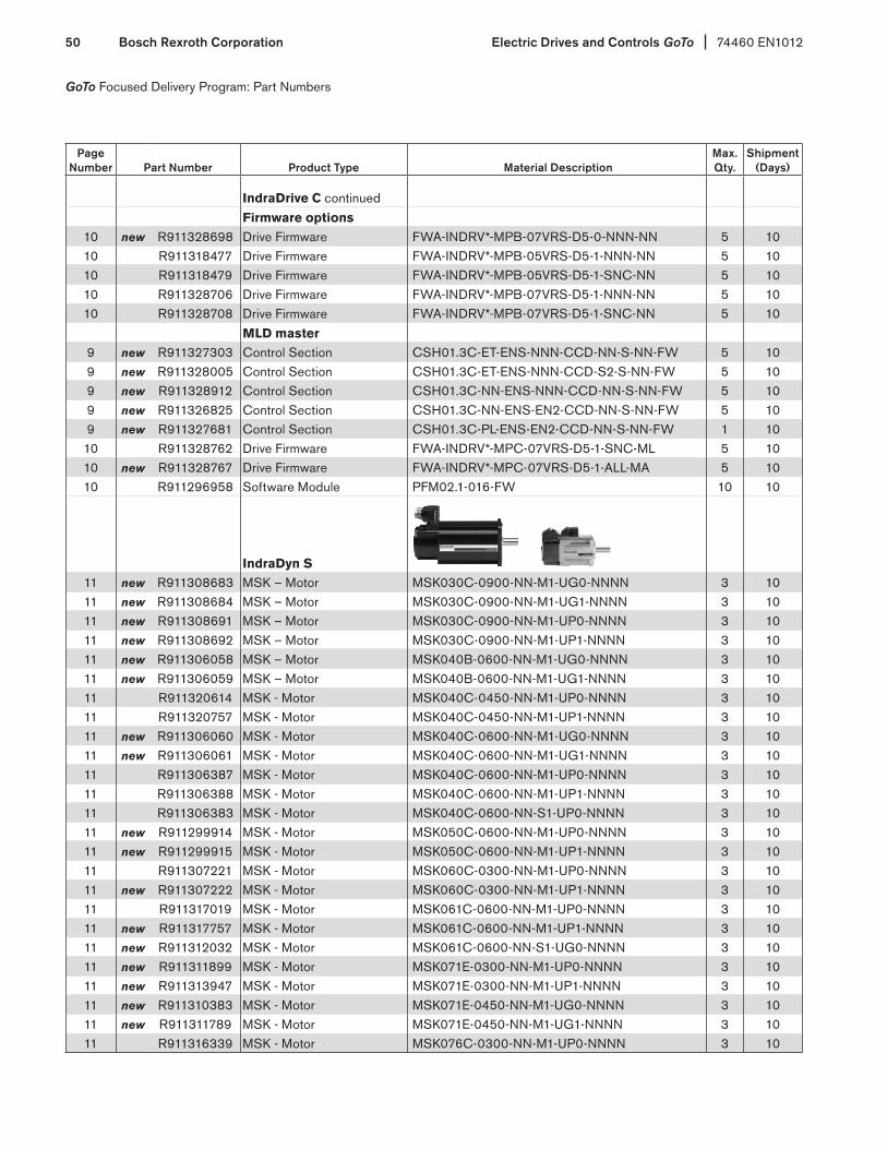
Electric Drives and Controls GoTo 74460 EN1012Bosch Rexroth Corporation50
GoTo Focused Delivery Program: Part Numbers
Page Number Part Number Product Type Material Description
Max. Qty.
Shipment (Days)
IndraDrive C continuedFirmware options
10 new R911328698 Drive Firmware FWA-INDRV*-MPB-07VRS-D5-0-NNN-NN 5 1010 R911318477 Drive Firmware FWA-INDRV*-MPB-05VRS-D5-1-NNN-NN 5 1010 R911318479 Drive Firmware FWA-INDRV*-MPB-05VRS-D5-1-SNC-NN 5 1010 R911328706 Drive Firmware FWA-INDRV*-MPB-07VRS-D5-1-NNN-NN 5 1010 R911328708 Drive Firmware FWA-INDRV*-MPB-07VRS-D5-1-SNC-NN 5 10
MLD master9 new R911327303 Control Section CSH01.3C-ET-ENS-NNN-CCD-NN-S-NN-FW 5 109 new R911328005 Control Section CSH01.3C-ET-ENS-NNN-CCD-S2-S-NN-FW 5 109 new R911328912 Control Section CSH01.3C-NN-ENS-NNN-CCD-NN-S-NN-FW 5 109 new R911326825 Control Section CSH01.3C-NN-ENS-EN2-CCD-NN-S-NN-FW 5 109 new R911327681 Control Section CSH01.3C-PL-ENS-EN2-CCD-NN-S-NN-FW 1 1010 R911328762 Drive Firmware FWA-INDRV*-MPC-07VRS-D5-1-SNC-ML 5 1010 new R911328767 Drive Firmware FWA-INDRV*-MPC-07VRS-D5-1-ALL-MA 5 1010 R911296958 Software Module PFM02.1-016-FW 10 10
IndraDyn S 11 new R911308683 MSK – Motor MSK030C-0900-NN-M1-UG0-NNNN 3 1011 new R911308684 MSK – Motor MSK030C-0900-NN-M1-UG1-NNNN 3 1011 new R911308691 MSK – Motor MSK030C-0900-NN-M1-UP0-NNNN 3 1011 new R911308692 MSK – Motor MSK030C-0900-NN-M1-UP1-NNNN 3 1011 new R911306058 MSK – Motor MSK040B-0600-NN-M1-UG0-NNNN 3 1011 new R911306059 MSK – Motor MSK040B-0600-NN-M1-UG1-NNNN 3 1011 R911320614 MSK - Motor MSK040C-0450-NN-M1-UP0-NNNN 3 1011 R911320757 MSK - Motor MSK040C-0450-NN-M1-UP1-NNNN 3 1011 new R911306060 MSK - Motor MSK040C-0600-NN-M1-UG0-NNNN 3 1011 new R911306061 MSK - Motor MSK040C-0600-NN-M1-UG1-NNNN 3 1011 R911306387 MSK - Motor MSK040C-0600-NN-M1-UP0-NNNN 3 1011 R911306388 MSK - Motor MSK040C-0600-NN-M1-UP1-NNNN 3 1011 R911306383 MSK - Motor MSK040C-0600-NN-S1-UP0-NNNN 3 1011 new R911299914 MSK - Motor MSK050C-0600-NN-M1-UP0-NNNN 3 1011 new R911299915 MSK - Motor MSK050C-0600-NN-M1-UP1-NNNN 3 1011 R911307221 MSK - Motor MSK060C-0300-NN-M1-UP0-NNNN 3 1011 new R911307222 MSK - Motor MSK060C-0300-NN-M1-UP1-NNNN 3 1011 R911317019 MSK - Motor MSK061C-0600-NN-M1-UP0-NNNN 3 1011 new R911317757 MSK - Motor MSK061C-0600-NN-M1-UP1-NNNN 3 1011 new R911312032 MSK - Motor MSK061C-0600-NN-S1-UG0-NNNN 3 1011 new R911311899 MSK - Motor MSK071E-0300-NN-M1-UP0-NNNN 3 1011 new R911313947 MSK - Motor MSK071E-0300-NN-M1-UP1-NNNN 3 1011 new R911310383 MSK - Motor MSK071E-0450-NN-M1-UG0-NNNN 3 1011 new R911311789 MSK - Motor MSK071E-0450-NN-M1-UG1-NNNN 3 1011 R911316339 MSK - Motor MSK076C-0300-NN-M1-UP0-NNNN 3 10

74460 EN1012 Electric Drives and Controls GoTo Bosch Rexroth Corporation 51
GoTo Focused Delivery Program: Part Numbers
Page Number Part Number Product Type Material Description
Max. Qty.
Shipment (Days)
IndraDyn S continued11 new R911317624 MSK – Motor MSK076C-0300-NN-M1-UP1-NNNN 3 1011 new R911315350 MSK – Motor MSK100B-0300-NN-M1-BP0-NNNN 2 1011 new R911316856 MSK – Motor MSK100B-0300-NN-M1-BP1-NNNN 2 1011 new R911311545 MSK – Motor MSK100C-0300-NN-M1-BP0-NNNN 2 1011 new R911317729 MSK – Motor MSK100C-0300-NN-M1-BP2-NNNN 2 1011 new R911311852 MSK – Motor MSK101D-0450-NN-M1-BP0-NNNN 2 1011 new R911333387 MSK – Motor MSK101D-0450-NN-M1-BP2-NNNN 2 1013 new R911325131 MSM – Motor MSM019B-0300-NN-M0-CH0 3 1013 new R911325132 MSM – Motor MSM019B-0300-NN-M0-CH1 3 1013 new R911325135 MSM – Motor MSM031B-0300-NN-M0-CH0 3 1013 new R911325139 MSM – Motor MSM031C-0300-NN-M0-CH0 3 1013 new R911325140 MSM – Motor MSM031C-0300-NN-M0-CH1 3 1013 new R911325143 MSM – Motor MSM041B-0300-NN-M0-CH0 3 1013 new R911325144 MSM – Motor MSM041B-0300-NN-M0-CH1 3 10
Additional Components14 R911286918 Line Filter NFD03.1-480-016 2 314 R911286919 Line Filter NFD03.1-480-030 2 314 R911286920 Line Filter NFD03.1-480-055 2 314 R911306007 Basic Kit HAS01.1-065-NNN-CN 5 514 R911306008 Basic Kit HAS01.1-105-NNN-CN 5 512 R911306106 Shield Kit HAS02.1-002-NNN-NN 5 514 new R911321502 X41 connection adapter HAS05.1-007-NNL-NN 10 1014 new R911319770 X41 connection adapter HAS05.1-007-NNR-NN 10 10
Cables15 new R985003832 Motor Power RKL0013/005.0 (5m length) 3 1015 new R911324290 Motor Power RKL0013/000.0 (configurable length) 3 1215 new R985003490 Motor Power RKL0014/005.0 (5m length) 5 515 new R911324291 Motor Power RKL0014/000.0 (configurable length) 5 1215 R911331348 Motor Power RKL0019/005.0 (5m length) 5 515 R911331349 Motor Power RKL0019/010.0 (10m length) 5 515 new R911325407 Motor Power RKL0019/000.0 (configurable length) 5 1215 R911310648 Motor Power RKL4302/005.0 (5m length) 5 515 R911310649 Motor Power RKL4302/010.0 (10m length) 5 515 new R911305799 Motor Power RKL4302/000.0 (configurable length) 5 1215 R911310652 Motor Power RKL4303/005.0 (5m length) 5 515 R911310653 Motor Power RKL4303/010.0 (10m length) 5 515 new R911305798 Motor Power RKL4303/000.0 (configurable length) 5 1215 new R911312870 Motor Power RKL4309/005.0 (5m length) 5 515 new R911305180 Motor Power RKL4309/000.0 (configurable length) 5 1215 new R911337991 Motor Power RKL4324/005.0 (5m length) 5 515 new R911310116 Motor Power RKL4324/000.0 (configurable length) 5 12
15 R911310645 Motor Feedback RKG4200/005.0 (5m length) 5 5

Electric Drives and Controls GoTo 74460 EN1012Bosch Rexroth Corporation52
GoTo Focused Delivery Program: Part Numbers
Page Number Part Number Product Type Material Description
Max. Qty.
Shipment (Days)
Cables continued
15 R911310646 Motor Feedback RKG4200/010.0 (10m length) 5 515 new R911299435 Motor Feedback RKG4200/000.0 (configurable length) 5 1215 new R985003831 Motor Feedback RKG0033/005.0 (5m length) 3 1015 new R911324269 Motor Feedback RKG0033/000.0 (configurable length) 3 1215 new R911326091 Motor Feedback RKG0034/000.0 (configurable length) 3 1216 R911308248 Interface (optical) RKO0100/00.25 (0.25m length) 5 516 R911308242 Interface (optical) RKO0101/005.0 (5m length) 5 516 R911308243 Interface (optical) RKO0101/010.0 (10m length) 5 516 R911321548 Interface (Ethernet) RKB0011/005.0 (5m length) 5 516 R911317797 Interface (Ethernet) RKB0013/00.25 (0.25m length) 5 516 R911296708 Interface (RS232-Serial) IKB0041/002.0 (2m length) 5 516 new R911324240 Battery box SUP-E01-MSM-BATTERYBOX 3 10
Motion Control PAC
IndraControl L17 R911171363 IndraControl L25 CML25.1-3N-400-NN-NNC1-NW 1 518 R911331629 IndraMotion MLC Firmware FWA-CML25*-MLC-11VRS-D0 1 517 R911170255 IndraControl L40 CML40.2-SP-330-NA-NNNN-NW 1 5
R911299856 Connector Set R-IB IL CML S01-PLSET 10 518 R911320567 IndraMotion MLC Firmware FWA-CML402-MLC-04VRS-D0 1 517 R911170828 IndraControl L45 CML45.1-3P-500-NA-NNNN-NW 1 5
R911299856 Connector Set R-IB IL CML S01-PLSET 10 518 R911331630 IndraMotion MLC Firmware FWA-CML45*-MLC-11VRS-D0 1 5
I/O
Inline (IP20)19 R911170789 Power Module R-IB IL 24 PWR IN-PAC 5 319 R911170790 Power Module R-IB IL 24 SEG/F-PAC 5 319 R911170710 Power Module R-IB IL 24 SEG/F-D-PAC 5 320 R911170875 Bus Coupler R-IL S3 BK DI8 DO4-PAC 5 320 new R911172194 Bus Coupler R-IL PB BK DI8 DO4/CN-PAC 5 320 R911170971 Bus Coupler R-IL PB BK DP/V1-PAC 5 321 R911170826 Block I/O R-ILB S3 24 DI16 DIO16 5 322 R911170874 Block I/O analog R-ILB S3 AI4 A02 5 323 R911170750 Digital Input Module R-IB IL 24 DI 4-PAC 5 3

74460 EN1012 Electric Drives and Controls GoTo Bosch Rexroth Corporation 53
GoTo Focused Delivery Program: Part Numbers
Page Number Part Number Product Type Material Description
Max. Qty.
Shipment (Days)
Inline (IP20) continued23 R911170751 Digital Input Module R-IB IL 24 DI 8-PAC 5 323 R911170752 Digital Input Module R-IB IL 24 DI 16-PAC 5 323 R911170753 Digital Input Module R-IB IL 24 DI 32/HD-PAC 5 324 R911170754 Digital Output Module R-IB IL 24 DO 2-2A-PAC 5 324 R911170755 Digital Output Module R-IB IL 24 DO 4-PAC 5 324 R911170756 Digital Output Module R-IB IL 24 DO 8-PAC 5 324 R911170759 Digital Output Module R-IB IL 24 DO 8-2A-PAC 5 324 R911170757 Digital Output Module R-IB IL 24 DO 16-PAC 5 324 R911170768 Digital Output Module R-IB IL 24 DO 32/HD-PAC 5 325 R911170769 Digital Output Module R-IB IL 24/230 DOR 1/W-PAC 5 325 R911170758 Digital Output Module R-IB IL 24/230 DOR4/W-PAC 5 326 R911170784 Analog Input Module R-IB IL AI 2/SF-PAC 5 326 R911308494 Analog Input Module R-IB IL AI 8/IS-PAC 5 326 R911308493 Analog Input Module R-IB IL AI 8/SF-PAC 5 327 R911170786 Analog Output Module R-IB IL AO 2/U/BP-PAC 5 327 R911170787 Analog Output Module R-IB IL AO 1/SF-PAC 5 327 R911170436 Analog Output Module R-IB IL AO 2/SF-PAC 5 328 R911170785 Temperature Module R-IB IL TEMP 2 RTD-PAC 5 328 R911170431 Temperature Module R-IB IL TEMP 2 UTH-PAC 5 329 R911170440 Communication Module R-IB IL RS232-PRO-PAC 5 330 R911170788 Counter Module R-IB IL CNT-PAC 5 330 R911308491 Counter Module R-IB IL INC-IN-PAC 5 330 R911308594 Counter Module R-IB IL SSI-PAC 5 3
IndraControl S67 (IP67)31 R911171796 Power Divider S67-PWR-IN-M12 5 332 R911171782 Bus Coupler S67-PB-BK-DI8-M8 5 334 R911171787 Digital Input Module S67-DI8-M8 5 334 R911171788 Digital Input Module S67-DI8-M12 5 336 R911171789 Digital Output Module S67-DO8-M8 5 336 R911171790 Digital Output Module S67-DO8-M12 5 336 R911171791 Digital Output Module S67-DO8-M8-2A 5 336 R911171792 Digital Output Module S67-DO8-M12-2A 5 338 R911171793 Analog Input Module S67-AI4-U/I-M12 5 340 R911171795 Analog Output Module S67-AO4-U/I-M12 5 342 R911171794 Temperature Module S67-AI4-RTD-M12 5 344 R911308301 Profibus cable IKB0048/005.0 (5m length) 3 544 R911308300 Profibus cable IKB0049/005.0 (5m length) 3 544 R911308250 Profibus cable IKB0050/000.3 (0.3m length) 3 5
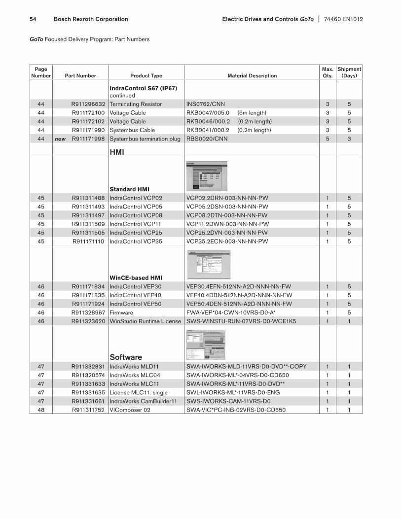
Electric Drives and Controls GoTo 74460 EN1012Bosch Rexroth Corporation54
GoTo Focused Delivery Program: Part Numbers
Page Number Part Number Product Type Material Description
Max. Qty.
Shipment (Days)
IndraControl S67 (IP67) continued
44 R911296632 Terminating Resistor INS0762/CNN 3 544 R911172100 Voltage Cable RKB0047/005.0 (5m length) 3 544 R911172102 Voltage Cable RKB0046/000.2 (0.2m length) 3 544 R911171990 Systembus Cable RKB0041/000.2 (0.2m length) 3 544 new R911171998 Systembus termination plug RBS0020/CNN 5 3
HMI
Standard HMI45 R911311488 IndraControl VCP02 VCP02.2DRN-003-NN-NN-PW 1 545 R911311493 IndraControl VCP05 VCP05.2DSN-003-NN-NN-PW 1 545 R911311497 IndraControl VCP08 VCP08.2DTN-003-NN-NN-PW 1 545 R911311509 IndraControl VCP11 VCP11.2DWN-003-NN-NN-PW 1 545 R911311505 IndraControl VCP25 VCP25.2DVN-003-NN-NN-PW 1 545 R911171110 IndraControl VCP35 VCP35.2ECN-003-NN-NN-PW 1 5
WinCE-based HMI46 R911171834 IndraControl VEP30 VEP30.4EFN-512NN-A2D-NNN-NN-FW 1 546 R911171835 IndraControl VEP40 VEP40.4DBN-512NN-A2D-NNN-NN-FW 1 546 R911171924 IndraControl VEP50 VEP50.4DEN-512NN-A2D-NNN-NN-FW 1 546 R911328967 Firmware FWA-VEP*04-CWN-10VRS-D0-A* 1 546 R911323620 WinStudio Runtime License SWS-WINSTU-RUN-07VRS-D0-WCE1K5 1 1
Software47 R911332831 IndraWorks MLD11 SWA-IWORKS-MLD-11VRS-D0-DVD**-COPY 1 147 R911320574 IndraWorks MLC04 SWA-IWORKS-ML*-04VRS-D0-CD650 1 147 R911331633 IndraWorks MLC11 SWA-IWORKS-ML*-11VRS-D0-DVD** 1 147 R911331635 License MLC11. single SWL-IWORKS-ML*-11VRS-D0-ENG 1 147 R911331661 IndraWorks CamBuilder11 SWS-IWORKS-CAM-11VRS-D0 1 148 R911311752 VIComposer 02 SWA-VIC*PC-INB-02VRS-D0-CD650 1 1

For engineers and OEM project managers on the go, Bosch Rexroth has a GoTo Products app in the iTunes® App Store. It’s now faster and easier than ever for Rexroth customers to browse the industry’s most popular collection of products for manufacturing, automation, and machinery engineering.
The GoTo app helps users find the information they need quickly and easily: User friendly search tools make it easy to find the right technology or part number from among Rexroth’s thousands of Drive & Control products and jump instantly to basic product and technical information. The app lets users build product lists and e-mail them, create “favorites” lists, view helpful product videos, and connect with Bosch Rexroth in the U.S. on Facebook, Twitter, and You- Tube—all from one easy interface. And the Sync-on-Demand feature ensures that you always have the latest data.
Bosch Rexroth’s GoTo Focused Delivery Program stream-lines everything to make it easier to get a selection of Rexroth’s most popular products faster. The GoTo Products app carries the program a significant step further by putting critical GoTo information at the ready, anywhere at anytime. Look for it in the iTunes App Store by searching for “Bosch Rexroth” or “GoTo Products.”
For more information on our GoTo Program and the apps for iPhone® and iPad®, visit www.boschrexroth-us.com/GoTo
GoTo Products app: New digital tools add even more speed to GoTo Focused Delivery ProgramThe GoTo Products apps for iPhone® and iPad® put the power of Rexroth’s GoTo Focused Delivery Program at your fingertips. Find products, connect with your distributor, get GoTo updates, and more.

USABosch Rexroth CorporationElectric Drives and Controls5150 Prairie Stone ParkwayHoffman Estates, IL 60192-3707Telephone (847) 645-3600Facsimile (847) 645-6201
Bosch Rexroth CorporationHydraulics2315 City Line RoadBethlehem, PA 18017-2131Telephone (610) 694-8300Facsimile (610) 694-8467
Bosch Rexroth CorporationLinear Motion and Assembly Technologies14001 South Lakes DriveCharlotte, NC 28273Telephone (800) 438-5983Facsimile (704) 583-0523
Bosch Rexroth CorporationHydraulics8 Southchase CourtFountain Inn, SC 29644-9018Telephone (864) 967-2777Facsimile (864) 967-8900
Bosch Rexroth CorporationPneumatics1953 Mercer RoadLexington, KY 40511-1021Telephone (859) 254-8031Facsimile (859) 281-3491
Bosch Rexroth CorporationCorporate Headquarters 14001 South Lakes DriveCharlotte, NC 28273Telephone (800) 438-5983Facsimile (704) 583-0523 www.boschrexroth-us.com
74460 EN1012 Replaces: 74460 EN0512© Bosch Rexroth Corporation 2012 Printed in the United States
Bosch Rexroth Regional Sales Offices:Central Bosch Rexroth Corporation 5150 Prairie Stone ParkwayHoffman Estates, IL 60192-3707Telephone (847) 645-3600Facsimile (847) 645-6201
Great LakesBosch Rexroth Corporation2730 Research DriveRochester Hills, MI 48309Telephone (248) 267-4000Facsimile (248) 853-2033
NortheastBosch Rexroth Corporation99 Rainbow RoadEast Granby, CT 06026Telephone (860) 844-8377Facsimile (860) 844-8595
Bosch Rexroth Corporation2315 City Line RoadBethlehem, PA 18017-2131Telephone (610) 694-8300Facsimile (610) 694-8467
Southeast Bosch Rexroth Corporation 14001 South Lakes DriveCharlotte, NC 28273Telephone (800) 438-5983Facsimile (704) 583-0523
Southwest Bosch Rexroth Corporation 1520 Selene Drive, Suite 104 Carrollton, TX 75006 Telephone (972) 245-6718Facsimile (972) 242-2850
West Bosch Rexroth Corporation7901 Stoneridge Drive, Suite 220Pleasanton, CA 94588Telephone (925) 227-1074Facsimile (925) 227-1081
Bosch Rexroth Corporation15271 Barranca ParkwayIrvine, CA 92618Telephone (949) 585-5460
The data specified herein only serves to describe the product. No statements concerning a certain condition or suitability for a certain application can be derived from our information. The given information does not release the user from obligation of own judgment and verifica-tion. It must be remembered that our products are subject to a natural process of wear and aging.
©This document, as well as the data, specifications and other information set forth in it, are the exclusive property of Bosch Rexroth Corpation. Without their consent it may not be repro-duced or given to third parties.