government of meghalaya - megphed.gov.in
TRANSCRIPT

Government of Meghalaya
Public Health Engineering Department
Turnkey Contract for
LAYING OF CLEAR WATER FEEDER MAINS AND REPLACEMENT OF
EXISTING DAMAGED CI FEEDER MAINS WITH DI PIPES FROM TREATMENT
PLANT TO DIFFERENT ZONAL RESERVOIR UNDER TURA PHASE-I & II W.S.S.
Bid Document
(General Technical Specification, Detailed Technical Specification & Drawings)
VOLUME : II

Executing Agency
Meghalaya State PHED

Contents Page i
CONTENTS
Chapter Descriptions Page
No.
Chapter : 1 General Technical Specification 1-28
Chapter : 2 Submittals 29-30
Chapter : 3 Site Preparation 31-32
Chapter : 4 Dismantling 33
Chapter : 5 Earth Work 34-43
Chapter : 6 Brick Work 44-48
Chapter : 7 Concrete Works 49-65
Chapter : 8 Form Work 66-69
Chapter : 9 Reinforcement 70-74
Chapter :10 Plastering 75-82
Chapter :11 Laying and Jointing of DI pipes 83-90
Chapter :12 Appurtenances 91-94
Chapter :13 Miscellaneous 95-96
Chapter :14 Technical specification for laying of clear water feeder
mains & replacement of old damaged CI Pipes
97
Drawing No.1 Legendary Map showing clear water feeder main &
replacement of old CI pipes.
GTS : General Technical Specification Page 1
Chapter 1
General Technical Specification
1.1 Materials.
The term “Materials” shall mean all materials, goods and articles of every kind whether raw,
processed or manufactured and equipment and plant of every kind to be supplied by the Contractor for incorporation in the works.
All materials shall be new and of the kinds and qualities described in the contract and shall be at least equal to approved samples.
Materials shall be transported, handled and stored in such a manner as to prevent deterioration, damage or contamination failing which such damaged materials will be rejected and shall not be used on any part of the works under this contract.
1.2 Samples and tests of materials.
The Contractor shall submit samples of such materials as may be required by the Engineer and shall carry out the specified tests directed by the Engineer at the site, at the supplier’s
premises or at a laboratory approved by the Engineer.
Samples shall be submitted and tests shall be carried out sufficiently early to enable further samples to be submitted and tested if required by the Engineer.
The Contractor shall give the Engineer minimum fifteen days notice in writing of the date on which any of the materials will be ready for testing or inspection at the supplier’s premises or
at a laboratory approved by the Engineer. The Engineer or his nominee shall attend the test at the appointed place within fifteen days of the said date on which the materials are expected to be ready for testing or inspection according to the Contractor, failing which the test may proceed in his absence unless instructed by the Engineer to carry out such a test on a mutually agreed upon date in his presence. The Contractor shall in any case submit to the Engineer within seven days of every test such number of certified copies (not exceeding six) of the test readings as the Engineer may require.

GTS : General Technical Specification Page 2
Approval by the Engineer for placing orders for materials or for samples or tests shall not prejudice any of the Engineer’s powers under the Contract particularly under the provisions of General Conditions of Contract.
The provisions of this clause shall also apply to materials supplied under any nominated sub-contract.
1.3 Standards.
The special attention of the Contractor is drawn to the relevant sections and clauses of the National Building Code of India (latest revision) and latest I.S. Specifications (latest editions as amended) and should follow all the specifications and conditions strictly.
Materials and workmanship shall comply with the relevant Indian Standards or any other National standards equivalent or higher than Indian standard (with amendments) current on the date of submission of bid only.
Where the relevant standard provides for the furnishing of a certificate to the Employer at his request, stating that the materials supplied comply in all respects with the standards, the Contractor shall obtain the certificate and forward it to the Engineer.
The specifications, standard and codes listed below are made a part of this specification. All standards, tentative specifications, specifications, code of practice referred to herein shall be the latest editions including all applicable official amendments and revisions.
If no standard is indicated, the relevant Indian Standard, if any, shall apply, Indian standards are published by:
Bureau of Indian StandardsManak Bhavan,9, Bahadur Shah Zafar Marg,NEW DELHI – 110 002.
In case of discrepancy between the specification and the Standards referred to herein, the Specification shall govern.

GTS : General Technical Specification Page 3
i) Materials – Applicable Indian Standards:
IS: 455 - 1989 Specification for Portland slag cement
IS: 1489 - 1991 Specification for Portland pozzolana cement
IS: 6909 - 1990 Specification for super sulphated cement
IS: 8041 - 1990 Specification for rapid hardening Portland cement
IS: 8043 - 1991 Specification for hydrophobic Portland cement
IS: 8112 - 1989 Specification for 43 grade ordinary Portland cement
IS: 12269 - 1987 Specification for 53 grade ordinary Portland cement
IS: 383 - 1970 Specification for coarse and fine aggregates from natural sources for concrete.
IS: 432 - 1982 Specification for mild (part I & II) steel and medium tensile steel bars and hard drawn steel wire for concrete reinforcement.
IS: 1786 - 1985 Specification for high strength deformed steel bars and wires for concrete reinforcement
IS: 4990 - 1993 Specification for plywood for concrete shuttering work.
IS: 1726 - 1991 Specification for Cast Iron Manhole Covers and Frames.
IS: 883 - 1994 Code of practice for design of structural timber in building.
IS: 1077 - 1992 Common Burnt Clay Building Bricks – Specification.
ii) Tests
IS: 516 - 1959 Method of test for strength of concrete
IS: 1199 - 1959 Method of sampling and analysis of concrete
IS: 2386 - 1963 Method of test for (Part I & VIII) aggregate for Concrete
IS: 5640 - 1970 Method of test for determining aggregate impact value of soft coarse aggregates
IS: 2720 Methods of test for soils (Parts I & XLI) (latest revisions)
IS: 3025 - 1964 Method for sampling and test (physical and chemical) for water used in construction.
iii) Code of practice
IS: 456 - 2000 Plain and Reinforced concrete – Code of Practice
IS: 800 - 1984 Code of practice for general construction in steel
IS: 2502 - 1963 Code of practice for bending and fixing of bars for concrete reinforcement
IS: 3558 - 1983 Code of practice for use of immersion vibrators for consolidating concrete
IS: 10005 - 1994 SI Units and Recommendations for the use of their Multiples and of certain other units.
IS: 10262 - 1982 Recommended guidelines for concrete mix design

GTS : General Technical Specification Page 4
iv) Construction Safety
IS: 3696 Safety code of scaffolds (Parts I & II) and ladders (latest revisions)
IS: 2750 - 1964 Specification for steel scaffolding
IS: 3764 - 1992 Code of safety for excavation work
v) Steel
IS: 2751 - 1979 Code of practice for welding of M.S. Plain & Deformed Bars for reinforced concrete construction
IS: 9417 - 1989 Recommendations for welding cold worked steel bars for reinforced concrete construction
IS:10790 - 1984 Methods of sampling of steel for prestressed and reinforced concrete part 2 reinforcing steel.
IS: 1566 - 1982 Specification for Hard-drawn steel wire fabric concrete reinforcement.
IS: 280 - 1978 Specification for Mild Steel Wire for General Engineering.
vi) Brickwork plastering
IS: 2116 - 1980 Specification for Sand for masonry mortars.
IS: 3495 - 1992 Methods of test of Burnt clay Building Bricks. (Part 1 – 4)
vii) Mass Concrete Dam :
IS: 6512 - 1984 Criteria for Design of solid Gravity Dams.
IS: 457 - 1957 Code of Practice for general construction of plain and reinforced concrete for Dams and other massive structures.
IS: 14591 - 1999 Specification for temperature control of Mass Concrete Dams-Guideline.
IS: 12966 (Pt-II) - 1990 Code of Practice for galleries and other openings in Dams.
IS: 4623 - 2000 Recommendations for structural design of Radial Gates.
viii) Sluice Valves
IS: 1364 Hexagon Head Bolts, Screws and Nuts of product Grade A and B (Part 1-latest revision)
IS: 638 - 1979 Specification for sheet rubber jointing and rubber insertion jointing.
GTS : General Technical Specification Page 5
IS: 2685 - 1971 Code of practice for selection, installation and maintenance of sluice valves.
IS: 14846 - 2000 Sluice valve for water works purposes (50 to 1200mm size) –
Specification.
ix) Butterfly Valves
IS: 13095 - 1991 Butterfly for general purpose
x) Ductile Iron Pipes
IS: 8329 - 2000 Centrifugally cast (spun) Ductile Iron pressure pipes for water, gas and sewage – Specification
IS: 5382 - 1985 Specification for Rubber sealing rings for gas mains, water mains and sewers.
IS: 3400 Methods of test for vulcanized rubbers (Part 1- 23 – latest revisions)
IS: 13655 - 1993 Guidelines for Heat Treatment of Cast Iron.
IS: 1500 - 2005 Methods for brinell hardness test for metallic materials.
IS: 9523 - 2000 Ductile Iron fittings for pressure pipes for Water, Gas & Sewage –Specification.
IS: 12288 - 1987 Code of practice for use and laying of Ductile Iron Pipes.
IS: 2062 - 1999 Steel for General Structural purposes – Specification.
xi) MS Pipes.
IS: 3589 - 1991 Electrically welded steel pipes for water, gas and sewage (200 to 2000mm nominal diameter)
IS: 3589 - 2001 Steel pipes for water, gas and sewage (168.3 to 2540mm outside diameter)
IS: 5822 - 1970 Code of Practice for laying of welded steel pipes for water supply
GTS : General Technical Specification Page 6
xii) MDPE Pipes and fittings
IS: 781 - 1984 Specification for cast copper alloy screw down bib taps and stop valves for water services.
IS: 778 - 1984 Specification for copper alloy gate, globe and check valves for water work purposes.
IS: 2692 - 1989 Specification for Ferrules for Water Services
xiii) Manuals
Manual on Water Supply and Treatment - CPHEEO (Central Public Health Environmental Engineering Organization)
1.4 Description of materials.
Bricks.
The bricks shall be class designation – 50, kiln-burnt bricks of regular and uniform size, shape and colour, well burnt throughout. They shall be free from cracks or other flaws viz. lumps of lime, laminations, soluble salts causing efflorescence, air-holes which may in any way impair their strength durability, appearance etc.
They shall give a clear metallic ringing sound when struck together.
After absorbing water the bricks shall not exceed 16% of their dry weight as per IS:No. 1077-19970. According to IS:No. 1077-1970 crushing load shall not be less than 50 Kg./Sqcm.
The brick to be used for the entire work shall be approved by the Engineer-in- Charge (EIC).
Sand.
The source from which sand is to be obtained shall be subject to the approval of Engineer-in-charge. The sand shall be clean, sharp and gritty to touch and be freed from earth and other impurities by washing.
GTS : General Technical Specification Page 7
The sand shall be washed to such a degree that when a handful is mixed with clean water in a glass and allowed to stand for an hour the precipitate of mud over the sand shall not exceed 5%.
Coarse sand : It is to be screened through a sieve of 64 meshes to the square inch so as to exclude large particles form the work. The fineness modulus shall not be less than 1.0. The size of Coarse Sand shall be within 4.75 mm to 2.00 mm.
Fine sand : It is to be screened through a sieve of 64 meshes to the square inch so as to exclude large particles from the work. The fineness modulus shall not be less than 2.5. The size of the fine sand shall be within 425 micron to 75 micron. The sand should conform to IS 382-1982 for fine and course aggregates from natural sources.
Stone chips.
It shall be obtained from crushing trap quartzite or hand stones and from quarries approved by Engineer-in-charge. It shall be of approved quality and proper grade. It shall pass through 20mm mesh and retained on 6mm mesh. It shall be free from dirt, leaves, clay and any organic matter. The material conforming generally to IS:383 1983 for course and fine aggregate from natural sources or IS:515-1959 for natural and manufactured aggregates for use in mass concrete with latest revisions.
Cement.
For all type of cement related to work. 43 grade Ordinary Portland Cement (OPC) conforming to relevant IS Codes is to be used depending upon the type of the structures.
Cement bags brought to the site must be stored in water tight shed as approved by the EIC. Any cement damage by water or otherwise, defective cement shall have to be removed from the site of work at once. Grade of cement to be used in the work as stated above shall be approved by the EIC before use.
Reinforcement.
Reinforcement steel bars : Fe 415 HYSD conforming to IS: 1786 shall be used. The bidder shall inform the Engineer incharge prior to start of work, regarding the type of steel to be used by him in the works and get them approved accordingly.

GTS : General Technical Specification Page 8
Straightening, shaping to form and Cutting steel works : The steel section shall be straightened and cut to lengths specified and measured with a steel tape. The cut ends shall be finished smooth. No two pieces shall be welded to make up the required length of a member.
Hoisting and placing in Position the steel bars : Steel work shall be hoisted and placed in position carefully and in most cases mechanical appliances such as lifting tackle, winch and derrick, etc. shall be used. Minimum diameter/thickness of steel members including angles, which comes in contract with water, will not be less than 6 mm. R.S. Joist shall be used where necessary as per specification.
All types of steel material shall be of tested quality as per specification stated above. The steel materials shall be free from oil, dirt and loose rust. Any scale or loose rust shall be removed before use for which extra claim shall not be entertained.
Painting.
Painting for prevention of rust : Before hoisting, steel work including RSJ shall be thoroughly cleaned by giving one coat of red oxide paint of approved quality and after erection two coats of synthetic enamel paint. However covered surfaces shall be given 2 coats of synthetic enamel paint before erection. The paint shall be of approved manufacturer and as per the direction of Engineer-in-Charge.
Under water structural steel work shall be finished with anticorrosive paint of approved make before erection except for the surface coming in contact with concrete. Special care shall be taken for cleaning of corners. Painting shall be carried out during dry weather and according to the manufacturer’s specification and relevant IS code.
Hand railing of parapets and elevated floor of the Electrical panel shall be painted with two coats of approved synthetic enamel paint over a coat of zinc chromate.
All other steel surfaces shall have two coats of synthetic enamel paint over a coat of priming as specified by the manufacturer of the paint.
The make, shade and color of the paints shall have to be approved by the Engineer-in-charge before use.
Water.

GTS : General Technical Specification Page 9
The water to be used in making and curing of concrete, mortar etc. shall be free from objectionable quantities of silts, organic matter, injurious amount of oils, acids, salts and other impurities etc. as per IS-456-1978.
The Engineer-in-charge or his authorized representatives will determine whether or not such quantities of impurities are objectionable.
Such comparison will usually be made by comparison of compressive strength, water requirement, time of setting and other properties of concrete made with distilled or every clean water and concrete made with the water proposed for use, Permissible limit for solids when tested in accordance with I.S. 3025-1964 shall be as tabulated below:
1. Organic Permissible limit for solids maximum permissible limit
200 mg/litre.
2. Inorganic 3000 mg/litre.
3. Sulphate (As So 4) 500 mg/litre.
4. Chloride (As CI.) 2000 mg/litre for P.C.C and 1000 mg/litre for R.C.C. work
5. Suspended matter 2000 mg/litre.
If any water to be used in concrete, suspected by the engineer-in-charge/or his authorized representative of exceeding the permissible limits of solids, samples of water will be obtained and get it tested by Engineer-in-charge in accordance with IS- 3025-1964.
Cement Concrete.
The concrete shall consist of an aggregate of the proportion by volume defined in relevant schedule item or work. Only measured quantity shall be used.
Laying : The cement, sand and stone chips shall be mixed properly in mechanical mixer in such a manner as to avoid loss of water. The concrete shall be mixed until it is of even colour and uniform consistency throughout. As soon as the concrete is mixed it should be removed to the work in iron vessels as rapidly as practicable. The concrete laid will be vibrated for compaction by the vibrators. Slum test will be carried at site during execution of work.

GTS : General Technical Specification Page 10
Curing : The concrete laid shall not be disturbed and shall be kept thoroughly damped by means of wet matting and sand until it shall have become thoroughly set and hard enough toprevent its drying and cracking.
The aggregate shall consist of stone ballast of quality approved by Engineer-in-charge and shall consist of graded size 20 mm and down wards as per specification or the size mentioned in the item description
Contractor shall furnish on the site of work sufficient number of centering, moulds or templates for its expeditious execution. The forms shall be made in such a way and of such materials as will ensure a smooth surface on the finished concrete. Forms and centering shall be left in place until the concrete has set sufficiently to permit the removal without danger to the structure.
Curing of concrete should be done as per IS:456.
1.5 Brick Masonry Works.
Materials:
The brick works shall consist of bricks and motor in accordance with general specification and plans.
Soaking bricks:
All bricks shall be soaked in clean water in tank for a period of at least twelve hour immediately before use.
The contractor shall provide at his expense tanks of sufficient capacity to admit of the simultaneous immersion to two days supply of bricks for the work its normal rate of progress.
Laying :
All the best-shaped uniformly colored bricks shall be picked out and used for face work without any extra payment to the contractor. All bricks work shall be constructed in English bond and shall follow the type bond junctions etc.
GTS : General Technical Specification Page 11
Brickwork shall be laid in English bond with mortar in proportion to 4:1 i.e. (4 sand:1 cement) unless otherwise specified. No brickwork shall be carried out more than one scaffolding height of 1.5 meter in any stage.
Brickwork in foundation and superstructure not in contact with water shall be provided with 19 mm and 12-mm. thick plaster at inside and outside faces respectively. Cement and sand material ratio shall be 1:6 for structures not in contact with water and 1:4 with 20 mm. thick plaster cement punning in the waterside face and 12 mm. thick plastering prop at the other face shall be provided all courses unless other wise specified or ordered by the Engineer, shall be truly horizontal and the walls shall be taken up truly plumb. Mortar joints shall never exceed 10 mm in thickness and this thickness shall be uniform throughout.
Vertical joints in alternate courses shall come directly over one another.
The joints shall be racked out not less than 12mm deep when the mortar is green so as to provide proper key for the plaster or pointing to be done.
Each face brick shall be set with both bed and vertical joints quite full of motor.
No damaged or broken brick shall be used in any part of the work except such as may be cut to size for closing the course. Closers shall be clean out to size an indicated in English bond and shall be situated near the end of walls.
The masonry shall be carried up regularly and no step shall be allowed more than 60cm. where the masonry of one part has to be delayed, the work must be raked back at an angle not exceeding 45º Angles and Junctions.
At all angles forming the junction of walls, the brick shall at each alternate course be carried into their respective walls so as to thoroughly unite the work with English bond.
Care shall be taken that when a brick is left out to allow support for the scaffold pole on the wall face, such brick shall always be a header and that not more than one header for each pole shall be left out.
GTS : General Technical Specification Page 12
Scaffolding:
Proper scaffolding shall be provided whenever necessary having two sets of vertical supports and shall be subject to the approval of the Engineer; who may order the contractor to alter orstrengthen the scaffolding if he considers it necessary, without thus becoming responsible either for the safety of the work or workmen or for any additional payment.
Holes shall be made good by bricks to match the face work when scaffolding is removed.
1.6 Reinforced Cement Concrete.
All R.C.C. work shall be of the grade not leaner than, M20 & M25 as given in the schedule and specifications and as per IS code 456-2000. The materials will be measured by weight when dry. The stone chips shall be thoroughly screened before use. If necessary, it shall be washed with water and stacked as per direction of E.I.C.
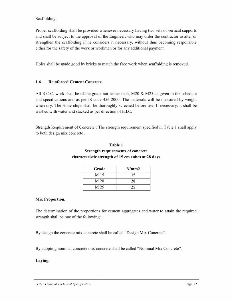
Strength Requirement of Concrete : The strength requirement specified in Table 1 shall apply to both design mix concrete .
Table 1Strength requirements of concrete
characteristic strength of 15 cm cubes at 28 days
Grade N/mm2M 15 15M 20 20M 25 25
Mix Proportion.
The determination of the proportions for cement aggregates and water to attain the required strength shall be one of the following:
By design the concrete mix concrete shall be called “Design Mix Concrete”.
By adopting nominal concrete mix concrete shall be called “Nominal Mix Concrete”.
Laying.
GTS : General Technical Specification Page 13
Cement, sand and stone chips shall be mixed properly in a mechanical mixer in such a manner as to avoid loss of water. The concrete shall be mixed for minimum period of 2 minutes or until it is of even color and uniform consistency throughout. As soon as the concrete is mixed it should be removed to the work in iron vessels as rapidly as practicable. The concrete laid will be vibrated for compaction by vibrators. Slum test will be carried at site during execution of work and confirm to IS – 456 – 2000.
Curing.
The concrete laid should not be disturbed and shall be kept damped by means of wet matting and sand until it shall have become thoroughly set and hard enough to prevent its during and cracking.
The aggregate shall consist of stone ballast of quality approved by Engineer-in-charge and shall consist of graded size 20 mm and downwards as per PWD specification or the size mentioned in the item description.
Form Work.
Contractor shall furnish on the site of work sufficient number of centering, forms, moulds or templates for its expeditious prosecution, the forms shall be made in such a way and such material as will ensure a very smooth surface on the finished concrete.
Forms and centering shall be left in place until the concrete has set sufficiently to permit the removal without danger to the structure.
1.7 Construction Joints.
Construction joints shall be provided, where directed and approved by the Engineer-in-charge. Such joints shall be kept minimum and shall be right angles to the direction of main reinforcement. In case of column and walls the joint shall be horizontal and 8 to 15 cm below the bottom of the beam or slab running into the column or wall head or below the anchor reinforcement of beam and slab coming into the column and wall and the portion of the column or wall between the stopping level and the top of slab shall be concreted with the beam or slab.Vertical Joints :
GTS : General Technical Specification Page 14
At the end of any days work or run of concrete, the concrete should be finished off against temporary shutter stop, which should be vertical and securely fixed. This stop should be removed as early as weather permits.
Horizontal Joints :
Horizontal joints should be washed down two hours after a casting in the manner described above for vertical joints.
If the concrete has been allowed to hard excessively, the surface shall be chipped over its whole surface to depth of at least 10 mm and there after thoroughly washed. Before fresh concrete is added on the other side of a construction joints, the surface of the old concrete will be thoroughly wetted then covered with a thin layer of cement mortar (1 cement : 2 sand).
All the construction joints in all concrete structure in contact with water or earth shall be provided with approved PVC water stops on both side with hot asphalt or approved metallic strips. The longitudinal joints in water stops shall be preferably hot welled.
Expansion joints.
Expansion joints shall be provided wherever directed by the engineer in charge, on where necessary as per standard specification and practice. The filler to be used shall be of approved material.
1.8 Cement plaster.
12 mm thick cement plaster in (1:4) proportion shall be applied on outside surface of all concrete works from 30cm below ground level up to top. The surface in contact with water will have 12 mm thick cement plaster of not less than (1:3) proportion with 3% water proofing compound. The concrete surface shall be properly hacked, washed, cleaned and applied with thick cement slurry before applying. All brick work unless otherwise specified will be plastered externally and internally with 12mm cement plaster (1:6) proportion.
The plaster shall be protected from sun, rain and frost at the contractors expense by such means as the engineer may approve. To protect the plaster from the sun, ordinarily the whole surface shall be covered with wet sakes.

GTS : General Technical Specification Page 15
The contractor shall keep the plaster continuously waited for a period of seven days after application.
1.9 Flooring.
Except where in otherwise specified flooring will have minimum 15cm thick sand filling, one brick flat soling and 75 mm thick PCC (1:2:4). In case flooring in raw water pump house 40 mm heavy duty patent stone flooring shall be provided directly over R.C.C. slab in strip placed in suitable manner to avoid construction cracks.
1.10 Door and window.
All windows shall be provided with aluminium grill of approved design.
All rolling shutter shall be of approved make and size with pusher and pull operated properly fabricated including all accessories and necessary fitting of approved quality.
All the doors and windows shall be painted with two coats of enamel paints over a coat of primer. Engineer in Charge shall approve the materials, the size, the shape and the fitting of doors and windows before put in position.
1.11 Roof and roof treatment.
R.C.C. roof slab of M 25 grade concrete of adequate thickness shall be constructed. The roof shall be treated with water proofing treatment as per CPWD specification and as per direction of E.I.C.
40 mm thick fine dressed stone flooring over 20mm (average thickness) base of cement mortar (1:2 proportion; 1 cement and 2 stone dust.) with an admixture of pigment shall be added.1.12 Snowcem washing.
The Raw water pump house shall have two coat of snowcem wash of approved shade over a coat of cement primer including preparing the plastered surface smooth with sand paper, scaffolding, centering etc. all complete as per building specification.
GTS : General Technical Specification Page 16
1.13 Moorum.
Moorum shall be of the best quality free from clay and must not be too brittle when dry nor too sticky when wet.
1.14 Jhama metals (for road works).
Jhama metals shall be obtained from uniformly vitrified and heavy picked Jhama brick bats. The colour of jhama metal shall be Copper red to black and shall not be spongy or with any coating of foreign materials. The jhama metals shall be more or less cubical in shape and size shall be well graded in between 90 mm to 45 mm.
1.15 Stone Aggregates (for road works).
Stone aggregates for road work shall be hard, clean, uniform and fine texture. These must be free from loam, clay or any surface coating, and free from organic matter and other impurities. Stone aggregates shall be well graded and size between 63 mm to 45 mm.
The quality and size of all road metals shall be approved by EIC.
Special Conditions
1.16 Conservation water.
The Contractor shall make his own arrangement for the fresh water required for construction of civil works and testing of pipeline and hydraulic structures as well as for the potable water required for his labour camps.
1.17 Construction power.
When supply of electrical energy is not possible for any reason the Contractor shall make his own arrangement for supply of electrical energy required at his sites and the works.
1.18 Temporary fencing.
GTS : General Technical Specification Page 17
The Contractor shall, at his own expense, erect and maintain in good condition temporary fences and gates along the boundaries of the areas assigned, if any, to him by the employer for the purpose of the execution of the works.
The Contractor shall, except when authorized by the Engineer, confine his men, materials and plant within the site of which he is given possession. The Contractor shall not use any part of the site for purposes not connected with the works unless prior written consent of the Engineer has been obtained. Access shall be made to such areas only by way of approved gateways.
1.19 Sanitary facilities.
The Contractor shall provide and maintain in clean and sanitary condition adequate W.C.’s
and wash places, which may be required on the various parts of the site or use of his employees, to the satisfaction of the Engineer. The Contractor shall make all arrangements for the disposal of sewage of drainage in accordance with the directions of the Engineer.
1.20 Restricted entry to site.
The Contractor shall get the prior permission of the Engineer before any person not directly connected with the works to visit the site.
1.21 Existing services.
Drains, pipes, cables, overhead electric wires and similar services encountered in the course of the works shall be guarded from injury by the Contractor at his own cost, so that they may continue in full and uninterrupted use to the satisfaction of the Employer and the Contractor shall not store materials or otherwise occupy any part of the ‘site’ in a manner likely to hinder
the operation of such services. The Contractor must make good or bear the cost of making good, the damage done by him on any mains, pipes, cables or lines (whether above or below ground), whether shown or not shown in the drawings, without delay to the satisfaction of the Engineer and the Employer.
1.22 Electric power supply.
The Contractor is forewarned that there can be interruptions in power supply for reasons beyond the control of the State Electricity Board and therefore the contractor is advised to make his standby arrangement to provide and maintain all essential power supply for his
GTS : General Technical Specification Page 18
work area at his expense. The contractor shall not be entitled to any compensation for any loss or damage to his machinery or any equipment or any consequential loss in progress of work and idle labour as a result of any interruptions in Power supply.
1.23 Notice to telephone & electricity supply under taking.
Before commencing operations, the contractor has to obtain permission from State PWD when he wants to cut any section of the road. The employer will give necessary assistance such as sending letters and attending meetings if required. The employer will also pay necessary charges towards restoration of roads to the State Highways and National Highways. Any delay in getting the permission from the State PWD, Electricity Board, BSNL Telecom Department, Traffic Department attached to the police and other departments for carrying out the work will be to the account of contractor.
The contractor before taking up operations, which involve cutting of roads, shifting utilities etc., during the progress of the work, shall give notice to the concerned authorities viz. State PWD, Electricity Board, Telecom Department, Traffic Department attached to the police and other departments as may be affected by the work. The notice should identify the specific details so that the necessary diversion of traffic may be arranged and permissions obtained. The contractor shall co-operate with the department concerned and provide for necessary barricading of roads, protection to existing underground cables etc., met with during the excavation of trenches. The contractor shall provide at his own expenses watching and lighting arrangements during day and night and erect required notice board such as “Caution
Road closed for Traffic” etc.. He should also provide and maintain at his own cost the necessary supports for underground cables etc., to afford best protection to them in consultation with the authorities in charge of the properties and to their best satisfaction. The contractor should obtain all approvals for installation and commissioning of machinery and accessories offered by them from the respective inspecting authorities such as Inspectorate of Electricity, etc.. Fees if any, to be paid to the inspecting authorities will be reimbursed by the Employer.1.24 Permission for road cuts.
Wherever the Contractor considers that it is necessary to cut through an existing road he shall submit details to the Engineer for approval, a minimum of seven days before such work commences. In the event of cutting a road by the Contractor without the written permission from the Engineer, the Contractor shall be responsible for the cost of reinstating the road as undertaken by the State PWD, as the case may be, notwithstanding the general proceduresincluded in Chapter 5, Earthwork. Where all permissions are correctly obtained the cost of such reinstatement will be paid directly by the employer.
GTS : General Technical Specification Page 19
1.25 Temporary diversion of roads.
During the execution of the work the Contractor shall make at his cost all necessary provision for the temporary diversion of roads, footpaths, drains, water courses, channels etc., if he fails to do so, the same shall be done by the Engineer and the cost thereof will be recovered from the Contractor.
1.26 Barricading.
The manhole/trench shall be barricaded on all four sides. The Contractor who has dug up the trench shall be responsible for any mishap, which may occur. Non-barricading of trenches by the Contractor shall be liable for a fine of Rs.500/- per day, per location from the interim payment. Such deduction will not relieve the Contractor of any liability or duty under the Contract.
1.27 Filling in holes and trenches etc.
The Contractor immediately upon completion of the Works shall fill up holes and trenches which may have been made or dug, level the mounds, or heaps or earth that may have been raised or made, and clear away all rubbish which may have become superfluous or have been occasioned or made in the execution of the works, and the Contractor shall bear and pay all costs, charges etc.
1.28 Accidents.
It shall be the duty of the Contractor to arrange for the execution of the works in such a manner as to avoid the possibility of the accidents to persons or damage to the properties at any state of the progress of work. Nevertheless he shall be held wholly responsible for any injury or damage to persons and properties, which may occur irrespective of any precautions he may take during the execution of the works. The Contractor shall make good all claims and loss arising out of such accidents and indemnify the Employer from all such claims and expenses on account thereof.
1.29 Water and lighting.
GTS : General Technical Specification Page 20
The Contractor shall pay all fees and provide water and light as required from Municipal mains or other sources and shall pay all charges, thereof (including storage tanks, meters etc.) for the use of the works and workmen, unless otherwise specified elsewhere in these documents or arranged and decided on by writing with Engineer.
The water used for the works shall be free from earthy vegetable or organic matter and from salts or other substances likely to interfere with the setting of mortar or otherwise prove harmful to the work and conform to relevant standards.
1.30 Payment to labourers.
The Contractor should note, that in the event of emergency, he shall pay all labourers every day. The Contractor shall not employ any labourer below age of 15 years.
1.31 Equivalence of standards and codes.
Whenever reference is made in the contract to the respective standards and codes in accordance with which plant, equipment or materials are to be furnished and work is to be performed or tested the provisions of the latest current edition or revision of the relevant standards and codes in effect shall apply, unless otherwise expressly set forth in the contract. Where such standards and codes are national in character, or relate to a particular country or region, other authoritative standards which ensure equal or higher quality than the standards and codes specified will be accepted subject to the prior review and written approval by the

GTS : General Technical Specification Page 21
Engineer. Difference between the standards specified and the proposed authoritative standards must be fully described in writing by the Contractor and submitted to the Engineerwell in advance for approval. If on the prior review, the Engineer determines that such proposed deviations do not ensure equal or higher quality; the Contractor shall comply with the standards set forth in the contract documents.
The Contractor should use only accepted makes of materials and plant and should construct the entire Works according to Specifications, Standards, data sheets, drawings etc. If no makes are specified then only manufacturers of Plant and materials corresponding to the state of the Art technology and/or confirming to the latest Indian/International standards shall be used. Providing materials of approved quality and confirming to the standards does not relieve the Contractor from being responsible for the successful performance of all system components.
1.32 Safety provision.
General requirements for health and safety.
The safety provision shall be brought to the notice of all concerned by displaying on a notice board at a prominent place at the work spot, persons responsible for ensuring compliance with the safety provision shall be named therein by the Contractor.
To ensure effective enforcement of the rules and regulations relating to safety precautions, arrangements made by the Contractor shall be open to inspection by the Engineer or his representative and the inspecting officer.
Notwithstanding the above provision Contractor is not exempted from the operation of any other act or rules in force relating to safety provisions.
Protection of the public.
No material on any of the sites shall be so stocked or placed as to cause danger or inconvenience to any person or to the public. The contractor shall provide all necessary fencing and lights to protect public from accidents and shall be bound to bear expenses of defense of every suit, action or proceedings of law that may be brought by any person for injury sustaining, owing to neglect the above precautions and to any such suit, action or proceedings to any such person or which may with the consent of the Contractor be paid to compromise any claim by any such person.Scaffolding and ladders.
GTS : General Technical Specification Page 22
The Contractor shall ensure that suitable scaffolds are being provided for workers for all the works, which cannot safely be done from the ground or from solid construction, except suchshort period work, as can be done safely from ladders.
When a ladder is used an extra mazdoor shall be engaged for holding the ladder and if the ladder is used for carrying materials as well, suitable footholds and handholds shall be provided on the ladder and the ladder shall be given an inclination not steeper than ¼ to 1 (¼ horizontal to 1 vertical). IS code for scaffolding and ladders, IS:3696 Part-I and Part-II and its latest revision is to be followed. Every ladder shall be securely fixed. No portable single ladder shall be over 7m in length. Width between side rails in rung ladders shall in no case be less than 30cm. for ladders; this width shall be increased by atleast 6mm for each additional 30cm length. Uniform steps spacing shall not exceed 30cm.
Scaffolding or staging more than 3.25 metres above the ground or floor swung or suspended from an overhead support or erection with stationary support shall have guard rail properly attached bolted, braced or otherwise secured atleast at 1 metre high above the floor or platform and the scaffolding of staging and extending along the entire length of the outside and ends thereof with only such openings as may be necessary for the delivery of materials. Such scaffolding or staging shall be so fastened as to prevent it from swaying from the building or the structure.
All scaffolds, ladders and other safety devices mentioned or described herein shall be maintained in a safe condition and no scaffold, ladder of equipment shall be altered or removed while it is in use.
Working platforms.
Working platform, gangways and stairways shall be so constructed that they do not sag unduly or unequally and if height of a platform or gangways or stairway is more than 3.25 meters above ground level, it shall be closely boarded having adequate width and be suitably fenced. Every opening in the floor of a building or in a working platform shall be provided with suitable means to prevent fall of persons or materials by providing suitable fencing or railing with a minimum height of 1 meter. Safe means of access shall be provided to all working platforms and other working places.
GTS : General Technical Specification Page 23
Precautions when using electrical equipment’s.
Adequate precautions shall be taken to prevent danger from electrical equipment. When workers are employed on electrical installations, which are already energised, insulating mats, wearing apparel such as gloves, sleeves and boots, as may be necessary shall be provided. Workers shall not wear any rings, watches and carry keys or other materials, which are good conductors of electricity.
1.33 Demolition.
Before commencing any demolition work and also during the process of the work, safety code for demolition of building IS: 4130 of the latest revision shall be followed:
a) All roads and open areas adjacent to the work site shall either be closed or suitably protected.
b) No electric cable or apparatus, which is liable to be a source of danger for a cable or apparatus used by operator, shall remain electrically charged.
c) All practical steps shall be taken to prevent danger to persons employed from risk or fire or explosion or flooding. No floor, roof or other part of a building shall be so overloaded with debris or materials as to render it unsafe.
1.34 Safety equipment.
General requirements.
All necessary personal safety equipment as considered adequate by the Engineer shall be available for use of persons employed on the site and maintained in a condition suitable for immediate use and the Contractor shall take adequate steps to ensure proper use of equipment by those concerned.
a) Workers employed on mixing asphaltic materials, cement and lime mortars/concrete shall be provided with protective footwear, hand gloves and goggles
b) Those engaged in handling any materials which is injurious to eyes shall be provided with protective goggles.
c) Stone breakers shall be provided with protective goggles and protective clothing.
d) When workers are employed in confined spaces (sewers, manholes etc.), which are in use, the Contractor shall ensure that manhole covers are opened and manholes are ventilated atleast

GTS : General Technical Specification Page 24
for an hour before workers are allowed to get into them. Manholes so opened shall be cordoned-off with suitable railing and warning signals of boards provided to prevent accident to public. Before entry by any worker the Contractor shall ensure that a gas detector is lowered into the confined space and the atmosphere is shown to be safe.
e) The Contractor shall not employ men below the age of 15 and women on the work of painting with products containing lead in any form. Whenever men above the age of 18 are employed on the work of lead painting the following precautions shall be taken:
i) No paint containing lead or lead products shall be used except in the form of paste of ready-made paint.
ii) Suitable face masks shall be supplied for use by workers when paint is applied in the form of spray or a surface having lead paints dry rubbed and scarped.
iii) Contractor shall supply overalls to workmen and adequate facilities shall be provided to enable working painters to wash during and on cessation of working periods.
Working near water.
When the work is done near any place where there is risk of drowning, all necessary equipment shall be provided and kept ready for use and all necessary steps taken for prompt rescue of any person in danger and adequate provisions made for prompt first aid treatment of all injuries likely to be sustained during the course of the work.
Hoisting machines.
Use of hoisting machines and tackles including their attachments, anchorage and supports shall conform to the following:
a) i) These shall be of good mechanical construction, sound material and adequate strength and free from patent defects and shall be kept in good repair and in good working order.
ii) Every rope used in hoisting or lowering materials or as a means of suspension shall be of durable quality and adequate strength, and free from patent defects.
b) Every crane driver or hoisting appliance operator shall be properly qualified and no person under the age of 21 years shall be in-charge of an hoisting machine, including any scaffold winch or giving signals to operator.
c) In case of every hoisting machine and of every chain ring hook, shackle, swivel and pulley block used in hoisting machine or lowering or as means of suspension, safe working load shall be ascertained by adequate means. Every hoisting machine and all gear referred to above shall be plainly marked with safe working load in case of hoisting with safe working load. In case of

GTS : General Technical Specification Page 25
hoisting machine having a variable safe working load and the conditions under which it is applicable shall be clearly indicated. No part of any machine or of any gear referred to above in this paragraph shall be loaded beyond safe working load except for the purpose to testing.
d) Engineer shall notify the safe working load of the machine in case of departmental machine. As regards Contractor’s machine, the Contractor shall notify safe working load of each
machine to the Engineer. Whenever he brings to the site of work and get it verified by the Engineer.
Motors, gearing, transmission, electrical wiring and other dangerous parts or hoisting appliance shall be provided with such means so as to reduce to the minimum risk and accident descend of load; adequate precautions shall be taken to reduce to the minimum risk of any part of a suspended load becoming accidentally displaced.
1.35 Working with explosives.
The Contractor shall obtain prior permission of the competent authority for the site, manner and method of storing explosives near the site of work. All handling of explosives including storage, transport shall be carried out under the rules approved by the “Concerned
Department of the Government”.
1.36 Environmental protection work.
The Contractor have to take following measures during construction and commissioning of works for protection of environment as to avoid environmental impacts on air, water and land:
Site clearance.
The site clearance shall be done with minimum damage to existing structures flora and fauna, electricity and telephone lines and other infrastructure service.
Earthwork and excavation.
The Contractor shall inform the local authorities/government if any fossils, coins artifacts of value or antiquity, structures and other remains of geological or archaeological interests and excavation shall be stopped until identification of cultural relics by the authorized institution is complete.
GTS : General Technical Specification Page 26
The Contractor shall dispose off surplus/waste material at identified sites approved by the Engineer. The Contractor shall ensure that their is minimum hindrance to normal activities and business. The Contractor shall avoid damage to permanent structures and shall avoid loss of standing crops along the road.
Replanting of Trees and Bushes: The Contractor shall carry out replantation on areas/on the periphery of construction sites to minimize visual impact and soil erosion. The Contractor shall pay special attention to the type of trees to be replanted to prevent fouling of water through falling leaves and bird droppings A list showing the type of trees to be replanted shall be submitted to the Engineer for approval prior for undertaking any replantation.
Soil Erosion and Water Quality : The Contractor shall ensure that earth and stone do not siltup existing irrigation/drainage systems. The Contractor shall take suitable measures to prevent direct discharge of polluted waters from construction activity into lakes/rivers/irrigation channels.
The Contractor shall minimize exposure of soil types susceptible to wind and water erosion. The Contractor shall control run-off and erosion through proper drainage channels and structures.
Soil compaction.
The Contractor shall restrict traffic movements and use low ground pressure machines. The Contractor shall preserve topsoil to be replaced after completion of construction activity. The Contractor shall avoid wet soils as far as possible.
Social disruption.
The Contractor shall minimize interruptions to utility services through proper planning and scheduling of activities. The Contractor shall provide temporary roads and diversions as may be necessary for smooth flow of traffic and people.Dust/air pollution.
The Contractor shall provide effective dust control through sprinkling/washing of construction sites and access roads. The Contractor shall cover/water stockpiles and storage areas to prevent dust pollution. The Contractor shall cover trucks transporting construction materials to minimize spills. The Contractor shall have a preventive maintenance programme
GTS : General Technical Specification Page 27
for construction equipment and vehicles to meet emission standards. Oil shall not be used to control dust.
Noise Pollution : The Contractor shall normally undertake construction work during daytime only (between 7.30 to 18.00 hrs.) and when authorised to work beyond these hours adopt suitable noise control methods during such works. The Contractor shall maintain machines and trucks to keep them with low noise. The Contractor shall install sound barriers and plant tree as appropriate during construction. The Contractor shall monitor the level of noise near the construction site, factory sites and sensitive areas with the following frequency.
a) During construction period : 12 times a year each time including day and night.
b) During commissioning period : 4 times adhoc monitoring
Construction Camps :The Contractor shall take adequate measures such as provision of septic tank/pit latrines at construction site/camps. The Contractor shall provide crèches to working women labour. The Contractor shall provide drinking water conforming to IS:10500-1991.
The Contractor shall provide garbage can at suitable fixed place and the garbage shall be disposed off regularly.
Aesthetic Improvement: The Contractor shall through proper house keeping enhance aesthetic appearance of construction sites. The Contractor shall dispose off construction wastes at approved disposal sites. The Contractor shall repair pavements immediately following construction of pipeline and appurtenant structures.
The Contractor shall remove after completion of construction, all temporary structures and restore the project and surrounding areas nearest possible to the reconstruction condition.
GTS : General Technical Specification Page 28
Conservation of Ecological Resources: The Contractor shall not use farmland and forest belts as materials borrow sites. The Contractor shall not select arable land as material borrow site. In case excavation in arable land is unavoidable, topsoil layer (30cms depth) shall be saved and returned after construction work is completed so as to minimize impacts on ecosystem, agriculture and animal husbandry. The Contractor shall educate construction workers to protect natural resources, wild plants and animals.
1.37 Use of trade names.
Wherever reference is made in the contract to specific manufacturers or trade names the Contractor shall be entitled to substitute Plant and materials supplied by other manufacturers or producers. Such substitution shall be to the approvals of the Engineer, which will not be unreasonably withheld. At the request of the Engineer the Contractor shall provide information to establish that the substituted Plant and materials are equivalent or better than those referred to.
1.38 Direction by the engineer.
The Contractor is responsible for all activities relating to the construction of the works. Any reference in this Specification to the Engineer directing or ordering, prescribing etc. the Contractor shall be deemed to mean “Contractor to propose a methodology of construction
and to submit to the Engineer for approval”. Any such approval by the Engineer shall not limit the Contractor’s responsibilities relating to construction of the Works. Notwithstanding
this clause the Engineer shall be entitled to instruct the Contractor whenever the Engineer considers it necessary to do so. Where such an instruction is considered by the Contractor to represent additional work he shall inform the Engineer of his opinion before undertaking the work. No claim for additional work on the basis of an instruction by the Engineer can be considered where the Contractor has failed to provide such prior notification.
1.39 Definition of the engineer.
Any reference in the Contract Documents to the Engineer in charge, or Executive Engineer, or departmental officers, shall be taken to mean the Engineer.
GTS : General Technical Specification Page 29
Chapter 2
Submittals
2.1 Description.
This section covers additional requirements for submission of schedules, samples, certificates, etc., and forms a part of all other sections in which submittals are required. It is subjected to General Conditions of Contract.
Requirements of submissions to be included.
1. PERT/CPM Progress Schedule
2. Samples of all materials pertaining to this work
3. Material lists and equipment
4. Factory test reports
5. Certificates
6. Laboratory test reports
2.2 Requirements - CPM progress schedule.
Within 30 days of award of the tender, the Contractor shall submit a critical path method analysis for construction progress control and make such revisions as are required for approval. He shall clearly indicate all construction activities, sub activities and mileposts on a time-oriented basis, with the critical path fully identified for all activities. He shall update and resubmit the charts monthly, flag all slippages and mileposts and attach a narrative description of the proposed corrective actions to the resubmitted charts. The Contractor shall include the following minimum information for each activity and critical path item:
i. Date and initial submittal, as applicable.
ii. Ordering dates for long lead time items.
iii. Dates for materials on site.
iv. Testing and clean up.
v. Final completion and handing over.

GTS : General Technical Specification Page 30
2.3 Samples.
The Contractor has to submit samples of all materials used for the work prior to start of the works and get the approval of the Engineer in charge. He shall label or tag each sample or set of samples, identifying the manufacturer’s name and address, brand name, catalogue number,
project title he intends use.
2.4 Material lists and equipment data.
The Contractor has to submit all material lists, equipment lists etc. well in advance before starting the work and get the approval of the Engineer in charge.
GTS : General Technical Specification Page 31
Chapter 3
Site preparation
3.1 Clearing site.
Preliminary work are required to be done before laying of pipes including pegging out, clearing and disposal of shrubs, grasses, bushes, hedges, boulders, debris from the route.
This shall also include the removal of stumps, etc. or parts thereof lying along the alignment of pipe. The Contractor should inform the Engineer in charge before removing shrubs, grasses, etc. well in advance. The alignment of the mains shall be so fixed as to avoid cutting of any trees.
3.2 Removal of top soil, shrubs and other vegetation.
All shrubs, vegetation and other plants shall be removed and cleared from the selected stretch of the site. All debris and unsuitable material upto a depth of 30cm between ground level or road level shall be removed. All debris and unsuitable material shall be carted away from the site as per the direction of Engineer to a distance of 10 kms.
3.3 Utilities protection.
All utility lines and structures, which are to remain in service shall be protected by the contractor from any damage likely to result from his operations. Relocation wherever necessary will be done by the respective Service Departments on payment of compensation. No extra payment will be made for minor relocation, which does not require dislocation from existing condition and shifting to other location. In such a condition, the service lines shall be pushed slightly to facilitate laying of main and brought back to original position after the work is completed wherever necessary. The service lines should be supported at bottom with planks, posts, etc. and tied with ropes properly. Any damage to any utility resulting from the Contractor's operations shall be repaired at the Contractor's expense.
GTS : General Technical Specification Page 32
3.4 Pavement removal.
The Contractor must inform the other concerned departments well in advance before starting the work. The Contractor must provide and maintain proper and efficient traffic control system such as safety lamps, sign boards etc. operating day and night for the full duration of work. The employer shall not be responsible under any circumstances for any mishappenings therefore. For the purpose of payment for removal of pavement, steel tapes are to be used and the Engineer’s representative and Contractor or his representative shall take the measurement
jointly. The width of trenches shall be as per the specification drawing and only such widths shall be taken into account for computing quantities for payment. The Contractor has to pay restoration charges for width excavated in excess of prescribed width. For other elements of work such as making cross connections, fixing other appurtenances etc. the Engineer shall prescribe the dimensions for removal of pavement from time to time.
3.5 Maintenance of traffic and closing of streets.
The work shall be carried out in such a manner, which will cause the least interruption to traffic, and road/street may be closed in such a manner that it causes the least interruption to traffic. Where it is necessary for traffic to cross open trenches, suitable bridges shall be provided. Suitable signs indicating that a street is closed shall be placed and necessary detoursigns for the proper maintenance of traffic shall be provided.
3.6 Interruption to service.
No valve or other control of the existing services shall be operated with out the permission of the authority.
3.7 Work during nights.
No extra payment will be made for doing the work in the nights. The Contractor shall get prior approval from the Engineer in charge before starting the work during nights.
GTS : General Technical Specification Page 33
Chapter 4
Dismantling
4.1 Dismantling of existing structures.
The structure shall be dismantled carefully and materials removed without causing damage to the serviceable material to be salvaged, the part of the structure to be retained and any properties of structures nearby. Any avoidable damage to the articles to be salvaged and part of the structure shall be made good by the Contractor without extra claims. The Contractor shall be responsible for any injury to the lookers or the public.
Structure should be removed 45cm below Ground and portion which in any way comes within new construction shall be removed entirely. Contractor shall maintain register or the salvaged material, which shall have signature of the Engineer on entries made.
All the material obtained from the removed structure shall be the property of client. Serviceable materials shall be stacked neatly in such a manner as to avoid deterioration at site or at other places. Non-serviceable materials shall be disposed off by the Contractor without causing any inconvenience.
All rubbish shall be cleared off the site and the Ground let clean and clear and Rubbish and non-serviceable materials shall be carted away upto a distance of 10kms as per the direction of Engineer.
4.2 Measurement and payment.
The measurements of work shall be exact length and width and height of the dismantled structure. It shall be priced per unit of the Cubic metre. Any excavation that may be necessary for dismantling the structure below 45cm from ground level shall be paid under the item of Excavation and shall include labour for refilling, watering and ramming, spreading on site if required and for disposal of surplus earth.
Chapter 5
GTS : General Technical Specification Page 34
Earth Work
5.1 Description.
The work specified in this section includes the provision of all labour, machinery, construction equipment and other appliances required to perform all earthwork specified or required, in a sound, workmanlike manner.
5.2 General.
Excavation shall be required to be done for the following works:
a) Excavation for underground pipelines.
b) Excavations for valve chambers, Thrust blocks and Special structure
No separate payment shall be made for removal of shrubs, which are less than 100mm in diameter at breast height, grass, small bushes and stumps. The alignment of the main shall be so fixed as to avoid cutting of any trees. No extra payment shall be made to the Contractor for working in a confined space.
5.3 Classification.
The excavation work shall be classified into the following categories by inspection of faces of cutting:
i) Loamy, clayey soils like black cotton soils, red earth, hard gravel, mixture of gravel and soft disintegrated rock like shale, ordinary gravel, stony earth and earth mixed with fair sized boulders, except rock requiring blasting, chiseling, wedging etc.
ii) Hard rock and boulders to be removed by benching, chipping, chiseling, edging, barring and by controlled blasting wherever permissible.

GTS : General Technical Specification Page 35
5.4 Trench excavation.
General: Trench excavation means excavation of trenches into which the pipe is to be laid. Before commencing trench excavation, the route of the trenches shall be pegged out accurately and the natural ground levels and the alignment shall be agreed with the Engineer in charge. The contractor shall dig probing pits or appropriate size and depth including cutting the road at every 100m interval or as directed by Engineer in charge.
Stripping surface materials: Before the surface of any part of the site is disturbed or the works there on are started, the Contractor shall take and record levels in the presence of the Engineer or his representative. Before commencing the excavation, the surface materials shall be carefully stripped and set aside for reuse as directed by the Engineer.
5.5 Width of trench.
The width of the trench at bottom between the faces of sheeting shall be nominal diameter of the pipe plus 300mm clearance on either side of the pipe. Trenches shall be of such extra width, when required as will permit the convenient placing of timber supports, strutting and planking and handling of specials. The width of trenches measured at the crown of the pipeshall permit adequate working space. The trenches shall be widened at sockets and other structures as may be found necessary.
Care should be taken to avoid excessive trench width and thereby increasing the load on the pipes.
5.6 Depth of excavation of trenches.
The depths for the trenches will be calculated from the surface to the bed of the pipes and in case when a layer of bedding is to be placed below the pipeline, the depth to the bottom of the bedding will be paid.
The trench shall be so dug that the pipeline may be laid to the required gradient and to the required depth, mentioned in the Table below. A minimum cover of 1.2m is to be provided above the crown level of pipe upto the Ground level / Road level.
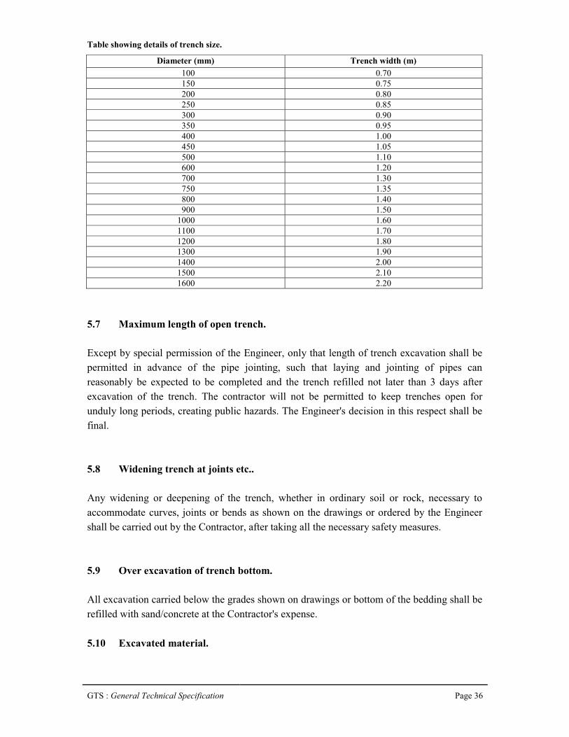
GTS : General Technical Specification Page 36
Table showing details of trench size.
Diameter (mm) Trench width (m)100 0.70150 0.75200 0.80250 0.85300 0.90350 0.95400 1.00450 1.05500 1.10600 1.20700 1.30750 1.35800 1.40900 1.50
1000 1.601100 1.701200 1.801300 1.901400 2.001500 2.101600 2.20
5.7 Maximum length of open trench.
Except by special permission of the Engineer, only that length of trench excavation shall be permitted in advance of the pipe jointing, such that laying and jointing of pipes can reasonably be expected to be completed and the trench refilled not later than 3 days after excavation of the trench. The contractor will not be permitted to keep trenches open for unduly long periods, creating public hazards. The Engineer's decision in this respect shall be final.
5.8 Widening trench at joints etc..
Any widening or deepening of the trench, whether in ordinary soil or rock, necessary to accommodate curves, joints or bends as shown on the drawings or ordered by the Engineer shall be carried out by the Contractor, after taking all the necessary safety measures.
5.9 Over excavation of trench bottom.
All excavation carried below the grades shown on drawings or bottom of the bedding shall be refilled with sand/concrete at the Contractor's expense.
5.10 Excavated material.
GTS : General Technical Specification Page 37
The material from the excavation shall be deposited on either side of the trench leaving clear berm on one side at least 40cm wide or at such further distance from the edges of the trench as may be necessary to prevent the weight of materials from causing the side of the trench to slip or fall, or at such a distance and such a manner as to avoid any wall or structure or causing inconvenience to the public or other persons or otherwise as the Engineer may direct, till it is carted away.
The excavated soil should be so placed and handled as not to inconvenience the usual traffic, till it is carted away. The Contractor should also provide necessary bridging over the excavated trenches for the house-holders and pedestrians to cross over and vehicular crossings if and where required at no extra cost; if the Engineer decides that there is no hindrance to traffic due to not carting away the excavated earth, he will give instructions to that effect. The Contractor shall be responsible for making all arrangements for the disposal of surplus excavated material upto a distance of 10kms.
5.11 Pipe bedding.
Sand Bedding: Where specified, the river sand bedding the required thickness and level shall be provided below pipe prior to laying the pipe in trenches. It shall be compacted with a light hand hammer. Any reduction in compaction shall be made up by adding sand during ramming. For the purpose of bedding under this item, only screened fine sand of grain size not larger than 2mm shall be used. The sand shall be clean, uncoated and free from clay lumps, injurious amount of dust, soft particles, organic matter, loam or other deleterious substances.
If the sand supplied is unclean, it shall be washed. In no case shall sand containing more than 3.5% by dry volume or 5% by wet volume of clay, loam or silt be accepted. Tests specified for determining silt in sand and organic impurities described in IS: 383 shall apply. Sieved and washed sand shall be stored on the works in such a manner as to prevent intrusion of any foreign matter, including coarser particle of sand or any clay or metal or chips. Tests as indicated above shall be performed if called for by the Engineer at the expense of the Contractor.
5.12 Excavation for appurtenance.
Excavation in trenches for foundation of valve chambers, pedestals etc. shall be as per the plan or as directed by the Engineer. The dimensions of the excavation shall be measured as the projection in plan of the outermost edges of the structure.5.13 Keep excavation clear of water.
GTS : General Technical Specification Page 38
Where ground water is encountered or anticipated, the Contractor shall provide sufficient pumps to handle the ingress of water and must provide and maintain in working order. Standby pumping units are to be made available and employed in the event of mechanical failure. The Contractor must also arrange for night and day operation of the pumps wherever necessary to ensure that the work proceeds at all times.
5.14 Dewatering in areas of high water table.
The Contractor shall perform dewatering as required so that all works of the contract are installed on dry areas and excavations, including without limitation the construction of all structures and underground piping. The Contractor shall ensure that dewatering is carried out only to a depth sufficient for the required excavation. The Contractor shall also ensure that, at all times, during construction, no groundwater shall come into contact with any concrete surface or reinforcement and that any structure shall be capable of withstanding any hydrostatic pressure to which it may be subjected during construction and until completed.
The Contractor shall be deemed to have included in the tender price for maintaining all works in a dry condition during construction. Any water removed from excavations shall wherever practicable, be pumped directly to the natural drainage channel or to storm sewers if approved via an efficient system of discharge lines. No water may be discharged into the sewerage system or onto open spaces.
The Contractor shall include for the diversion of all water courses encountered in the work until the scheme is completed and put into operation.
Notwithstanding any previous approval, the Contractor shall be fully responsible for maintaining dry excavations.
Where deemed necessary by the Engineer, working drawings and data shall be submitted for review or approval showing the intended plan for dewatering operations. Details of locations and capacities of dewatering wells, well points, pumps, sumps, collection and discharge lines, standby units, water disposal methods, monitoring and settlement shall be included. These shall be submitted not less than 30 days prior to start of dewatering operations.
The static water level shall be drawn down to a minimum of 300mm below the bottom of the excavation so as to maintain the undisturbed state of the foundation soils and allow the placement of any fill or backfill to the required density. The dewatering system shall be
GTS : General Technical Specification Page 39
installed and operated so that the groundwater level outside the excavation is not reduced to the extent that would damage or endanger adjacent structures or property.
5.15 Unsound foundations, soft spots.
When the specified levels of trench or structure are reached, the Engineer will inspect the ground exposed and if he considers that any part of the ground is by its nature unsuitable, he may direct the Contractor to excavate further and the further excavation shall be filled with concrete M-10 or river sand. Should the bottom of any trench or structure excavation, while acceptable to the Engineer at the time of his inspection subsequently become unacceptable due to exposure to weather conditions or due to flooding or have become puddled, soft or loose during the progress of the works, the Contractor shall remove such damaged, softened or loosened material and excavate further by hand. In this case, the cost of the extra excavation and of the additional foundation materials required will be the Contractor's responsibility if necessitated by his negligence.
The omission by the Engineer to give an instruction under this Clause shall not relieve the Contractor from any responsibility for defect in the works due to the construction being placed upon an unsuitable formation if prior to the construction of the work the Contractor shall have failed to call the attention of the Engineer thereto in writing.
If in the opinion of the Engineer, a formation is unsound as a result of the Contractor failing to keep the excavation free from water, the Engineer will order the removal and disposal of the unsound material and filling of the resulting void. The Contractor shall execute the work as directed and shall have no claim against the Board for any costs thus incurred.
5.16 Caution cum information boards.
Before commencing an excavation, "Caution-Cum-Information" board shall be installed at site by the Contractor. Such board shall remain at site as long as the trench remains open. The board shall be installed at both the ends of the trench atleast 100m before the approach to the area, if the trench is less than 600m in length. Additional boards at every 300m shall be installed, if the length of the trench exceeds 600m. If the streetlight is inadequate, lettering with fluorescent paint shall be used for these boards. The boards shall also contain information regarding dates of commencement and completion of the work, name and phone number of the Engineer in charge of the work. See also Clause 5.19. The size of lettering shall be adequate to be read by passing vehicles.
GTS : General Technical Specification Page 40
5.17 Barricading.
To prevent persons from injury and to avoid damage to the property, adequate barricades, construction sign, torches, red lanterns and guards as required shall be provided and maintained during the progress of the construction work and until it is safe for traffic to use the roadways. The manhole trench shall be barricaded on all four sides. Barricading for laying pipe lines consists of fixing casuarina posts 8-10cm dia. and 1.52m high at 1.53m centre to centre tied with coir ropes in two rows or by any other method as approved by the Engineer. Barrication also includes watching during night, fixing danger flags, danger lights/reflector and painting in different colours. The Contractor who has dug up the trench shall be responsible for any mishap, which may occur.
5.18 Fencing, watching, lighting.
The parts of the fencing shall be of timber, securely fixed in the ground not more than 2.50m apart, they shall not be less than 10cm in dia. or not less than 1.25m above the surface of the ground. There shall be no two rails, one near the top of the posts and the other about 0.50m above the ground and each shall be of 5cm to 10cm in diameter and sufficiently long to run from post to post to which they shall be tied with strong ropes. The method of projecting rails beyond the posts and tying together where they meet will not be allowed on any account. All along the edges of the excavated trenches, a bund of earth about 1m high shall be formed when so required by the Engineer for further protection. Proper provision shall be made for lighting at night and watchmen shall be kept to see that this is properly done and maintained. In addition to the normal lighting arrangements, the Contractor shall provide, whenever such work is in progress, battery operated blinking lights (6 volts) in the beginning and end of a trench with a view to provide suitable indication to the vehicular traffic. The Contractor shall also provide and display special boards printed with fluorescent prints indicating the progress of work along the road. In the event of the Contractor not complying with the provisions of the clause, it may be carried out by the Engineer and the cost recovered from the Contractor besides claiming liquidity damages from the contractor. In all such cases the work may be carried out by Board. The Contractor shall be held responsible for all claims for compensation as a result of accident or injury to persons/non-provision of red flags.
The Contractor shall at his own cost provide all notice boards before opening of roads as directed by the Engineer.
Arrangements shall be made by the Contractor to obtain permission from traffic authorities for working and to direct traffic when work is in progress. No separate payment shall be paid for this item of work.5.19 Refilling trenches.

GTS : General Technical Specification Page 41
a) With a view to restrict the length of open trenches, on completion of the pipe laying operations, refilling of trenches shall be started immediately by the Contractor. Pipe laying and testing shall follow closely upon the progress of trench excavation and the Contractor shall not be permitted more than 500 metres of trench excavation to remain open while awaiting testing of the pipe line.
b) Care shall be taken while back filling, not to injure or disturb the pipe. Filling shall be carried out simultaneously on both the sides of the pipes so that unequal pressure does not occur.
c) Walking or working on the completed pipelines shall not be permitted unless the trench has been filled to a height of at least 30cm over the top of the pipe except as may be necessary for tamping etc., during back filling work.
d) Filling-in shall be done in layers not exceeding 150mm in thickness accompanied by adequate watering, ramming etc. so as to get good compaction upto 300mm above the top of the pipe. Above this level, river sand shall be placed in layers of 200mm watered and compacted by tamping.
e) The trench shall be refilled so as to build up to the original ground level, keeping due allowance for subsequent settlement likely to take place.
f) Before and during the backfilling of the trench, precautions shall be taken against the floatation of the pipeline due to the entry of large quantities of water into the trench causing an uplift of the empty or the partly filled pipeline.
5.20 Permanent reinstatement.
a) Highways : Restoration and re-instatement of Highways head and sidewalk surface shall be done either by concerned Department and employer will pay the cost or by employer with due permission from concerned authority.
b) State roads : The reinstatement of the State roads, i.e. Asphalt and WBM roads and side walk surface will be carried out either by the concerned Department and employer will pay the cost or by employer with due permission from concerned authority.c) Private properties : However, any damages to the private properties such as compound wall, fencing, etc. during the execution or immediately afterwards due to

GTS : General Technical Specification Page 42
contractor carelessness, the same has to be restored by the Contractor to the original shape at Contractor’s own cost.
5.21 Shorting and strutting.
Open cuttings and trenches shall be suitably shored, sheeted and braced, if required by the Engineer or by site conditions or to meet local laws, for protecting life, property of the work.
Adequate shoring and strutting shall be provided by the Contractors at their own cost. Warped or deformed timber shall not be used. The shoring shall project at least 150mm above ground level and shall extend to a suitable depth below the bottom of the trench. Wherever necessary, the planks or struts shall be driven by compressed air pile drivers. The planks shall be fixed close enough to avoid any running in of sand earth through the joints. The shoring material shall not be of sizes less than those specified below, unless steel sheet piling is used or unless approved by the Engineer in writing.
a) Planks : 38mm thick
b) Walling pieces : 100 cm x 100 cm
c) Struts : 15 cm x 20 cm
For walling pieces round timber shall not be allowed. In a vertical plane, there shall be at least three struts or more as directed by the Engineer. They shall rest on walling pieces. The spacing of the struts shall be as per the requirement of the design. At the bottom, extra struts shall have to be provided if ordered by the Engineer. The rates for excavation do not include the cost of shoring, which shall be paid for separately as per relevant item of the bill of quantities. The contractors shall be held responsible for providing secure shoring, and for adopting every other precaution, which may be necessary for protecting nearby structures, which are likely to be damaged as a result of excavation. The contractors shall design the shoring required for actual site conditions and shall provide shoring accordingly. The design shall be submitted to the Engineer on demand. The shoring shall be so designed that lowering of pipe of normal length or any other pipe laying operation does not necessitate the removal of any strut or any other member of shoring. If the Engineer requires the adoption of any special measures or precautions, the contractor will comply with the same immediately. If any part of a nearby structure is cut out or removed for facility of work, the same shall be made good on completion of the work by the contractors at their cost.
In the event of the contractors not complying with the provisions of this contract in respect of shoring the Engineering may, with or without notice to the contractors, put up shoring or improve shoring already put up or adopt such other measures as he may deem necessary, the

GTS : General Technical Specification Page 43
cost of which shall be recovered from the contractors. Such action on the part of the Engineer, shall not, however absolve the contractors of their responsibilities under this contract.
No part of the shoring shall, at any time, be removed by the contractors without obtaining permission from the Engineer. While taking out shoring planks, the hollows formed shall be simultaneously filled in with soft earth and shall be well compacted as directed.
5.22 Quality control test.
Trenches other than in roads and paved areas shall be backfilled as specified in Clause 5.19.
GTS : General Technical Specification Page 44
Chapter 6
Brick Work
6.1 Brick work.
Masonry Mortars:
Proportioning:
Mix proportion of cement sand mortar shall be as indicated. The mixes specified are by volume. 50 kg. of cement shall be taken as equal to 0.035 cum. To determine bulk. The quantity of water to be added to cement sand mortar shall be such that working consistency is obtained. Excess water shall be avoided.
Preparation of cement mortar:
Mixing shall be done preferably in a mechanical mixer. If done by hand, mixing operation shall be carried out on a clean watertight platform. Cement and sand shall be mixed dry in the required proportion to obtain a uniform colour. The required quantity of water shall then be added and the mortar hoed back and forth for 5 to 10 minutes with additions of water to a workable consistency. In the case of mechanical mixing, the mortar shall be mixed for atleast three minutes after addition of water. Cement mortar shall be freshly mixed for immediately use. Any mortar, which has commenced to set, shall be discarded and removed from the site.
Time of use of mortar:
Mortars with cement as an ingredient shall be used as early as possible after mixing, preferably within half and hour from the time water is added to the mix or at the latest within one hour of its mixing.
Workability of masonry mortar:
The working consistency of the mortar is usually judged by the work during application. The water used shall be enough to maintain the fluidity of the mortar during application, but at the same time it shall not be excessive leading to segregation of aggregates from the cement.
6.2 Brick masonry:

GTS : General Technical Specification Page 45
a) Manufacture : Common burnt clay building bricks shall conform to the requirements of IS:1077 and shall be of quality not less than class 20 with moisture absorption rate not exceeding 15 percent as defined in IS:1077. The bricks shall be chamber burnt and shall have sharp corners and smooth faces and shall not be damaged in any manner and sizes shall conform to the works sizes specified with tolerances as given in 6.2 IS:1077.
b) Samples : The Contractor shall deliver samples of each type of brick to the Engineer, and no orders shall be placed without the written approval of the Engineer. All the bricks used in the works shall be of the same standard as the approved samples. The samples shall be preserved on site, and subsequent deliveries shall be checked for uniformity of shape, colour and texture against the samples. If in the opinion of the Engineer any deliveries vary from the standard of the samples, such bricks shall be rejected and removed from the site. Samples of bricks shall be tested in accordance with IS:3495 by the contractor.
c) Uniformity : The bricks selected for exposed pointed brickwork walls shall be of uniform colour, deep cherry red or copper colour, and uniform texture. Only such bricks as are permitted by the Engineer shall be used.
6.3 Setting out.
All brickworks shall be set out and built to the respective dimensions, thickness and heights as indicated.
6.4 Scaffolding.
Scaffolding shall be strong to withstand all dead, live and impact loads, which are likely to come on them. Scaffolding shall be provided to allow easy approach to every part of the work overhand work shall not be allowed.
For exposed brick facing double scaffolding having two sets of vertical supports shall be provided. For brickwork, which is to be plastered over, single scaffolding may be provided. In single scaffolding one end of the putlogs shall rest in the hole provided in the header course of brick masonry. Not more than one header for each putlog shall be left out. Such holes shall not be allowed in the case of pillars of narrow masonry portions between openings, which are less than one metre in width or are immediately under or near the structural member supported by the walls. The holes left shall be made good on removal of scaffolding to match with the face work/surrounding area.Timber or bamboo scaffolds shall be erected in accordance with the provisions contained in IS: 3696 (Part I)-1987. Safety code for scaffolds and ladders, Part I - Scaffolds, to ensure safety of workmen and others. Steel scaffolding shall be erected in accordance with the provisions contained in IS:2750-1964. Specifications for steel scaffolding and relevant
GTS : General Technical Specification Page 46
provisions of IS: 3696 (Part I) - 1987 for safety code for scaffolds (Parts I & II) and ladders shall be followed.
6.5 Soaking of bricks.
Bricks shall be soaked in water before use for a period of the water to just penetrate the whole depth of the bricks. Alternatively bricks may be adequately soaked in stacks by profusely spraying with clean water at regular intervals for a period not less than six hours. The bricks required for masonry work using mud mortar shall not be soaked. When bricks are soaked, they shall be removed from the tank sufficiently early so that at the time of laying they are skin-dry. Such soaked bricks shall be stacked-on clean place, where they are not again spoiled by dirt, earth, etc.
6.6 Laying.
All loose materials, dirt and set lumps of mortar which may be laying over the surface on which brickwork is to be freshly started, shall be removed with a wire brush and surface wetted slightly. Bricks shall be laid on a full bed of mortar. When laying, the bricks shall be properly bedded and slightly pressed with handle of trowel so that the mortar can get into all the pores of the brick surface to ensure proper adhesion. All the joints shall be properly flushed and packed with mortar so that no hollow spaces are left.
Care shall be taken to see that the required quantity of water is added to the mortar at the mixing platform to obtain required consistency. Addition of water during laying of the course shall not be permitted. In the case of walls two bricks thick and over, the joints shall be grouted at every course in addition to bedding and flushing with mortar.
Bricks shall be laid with frog up. However if the top course is exposed, bricks shall be laid with frog down. Care shall be taken to fill the frogs with mortar before embedding the bricks in position.
All quoins shall be accurately constructed and the height of courses checked with storey rods as the work proceeds. Acute and obtuse quoins shall be bonded, where practicable, in thesame way square quoins; obtuse quoins shall be formed with squint showing a three quarter brick on one face and quarter brick on the other.6.7 Bond.
All brickwork shall be built in English Bond, unless otherwise indicated. Half brick walls shall be built in stretcher bond. Header bond shall be used for walls curved on plan for better alignment. Header bond shall also be used in foundation footings, stretchers may be used
GTS : General Technical Specification Page 47
when the thickness of wall renders use of headers impracticable. Where the thickness of footings is uniform for a number of course of the footings shall be headers.
Half or cut bricks shall not be used except where necessary to complete the bond.
Overlap in stretcher bond is usually half brick and is obtained by commencing each alternate course with a half brick. The overlap in header bond which is usually half the width of the brick is obtained by introducing a three quarter brick in each alternate course at quoins. In general, the cross joints in any course of brickwork shall not be nearer than a quarter of brick length from those in the course below or above it.
6.8 Uniformity.
The brickwork shall be built in uniform layers; corners and other advanced work shall be raked back. No part of a wall during its construction shall be raised more than one metre above the general construction level, to avoid unequal settlement. Parts of walls left at different levels shall be properly raked back. Toothing may be done where future extension is contemplated but shall not be used as an alternative to taking back.
For half brick partition to be keyed into main walls, indents shall be left in the main walls.
6.9. Thickness of joints.
The thickness of joints shall be 10mm + 3 or – 3mm, unless otherwise specified. Thickness of joints shall be kept uniform. Slight difference to thickness of bricks shall be adjusted within joint thickness. Where brickwork is to match the existing work, the joints shall be of the same thickness as in the existing work.
6.10 Striking joints.
Where no pointing, plastering or other finish is indicted, the green mortar shall be neatly struck flush. Where pointing, plastering or other finish is indicated, the joints shall be squarely raked out to a depth not less than 10mm for plastering and 15mm for pointing.6.11 Curing.
The brickwork shall be constantly kept wet for atleast 7 days.
6.12 Facing.

GTS : General Technical Specification Page 48
In case of walls one brick thick and under, atleast one face shall be kept even and in proper plane, while the other face may be slightly rough. In case of walls more than one brick thick, both the face shall be kept even and in proper plane. For exposed brickwork selected bricks of the specified class and sub-class shall be used for the face work, where however, use of facing bricks is indicated, brick walls shall be faced with facing bricks. No rubbing down of brickwork shall be allowed.
Brick walls shall be plastered pointed or otherwise finished, as indicated. Joints of external faces of brick walls in foundation upto 15cm below ground level and of internal faces of brick walls in foundation and plinth below sub-floor level shall be struck flush when the mortar is green, as the work proceeds.
6.13 Cleaning.
Face of brickwork shall be cleaned on the same day it is laid and all mortar droppings removed.
6.14 Construction details.
Holes for Pipes etc.
All necessary holes for pipes, air flues, ventilators, etc. shall be cut or formed as work proceeds and grouted in cement and sand mortar 1:3 of cement concrete 1:2:4 as required and made good.

GTS : General Technical Specification Page 49
Chapter : 7
Concrete Works
7.1 Concrete.
General:
The quality of materials and method and control of manufacture and transportation of all concrete work irrespective of mix whether reinforced or otherwise, shall conform to the applicable portions of this Specification.
The Engineer shall have the right to inspect the sources of materials, the layout and operation of procurement and storage of materials, the concrete batching and mixing equipment, and the quality control system. Such an inspection shall be arranged and Engineer’s approval
obtained, prior to starting of concrete work.
7.2 Materials for standard concrete.
The ingredients to be used in the manufacture of concrete shall consist solely of Portland cement, clean sand, natural coarse aggregate, clean water, and admixtures, if specifically called for and conditions at site warrant its use.
a. Cement : Cement shall conform to IS: 12269 – 1987.
b. Aggregates : Aggregates shall comply with the requirements of IS:383-1970.
i. General
a) “Aggregate” in general designates both fine and coarse inert materials used in the manufacture of concrete.
b) “Coarse Aggregate” is aggregate most of which is not passed through on 4.75mm IS
sieve.
c) “Fine aggregate” is aggregate most of which is passed through on 4.75mm IS sieve.
d) All fine and coarse aggregate proposed for use in the works shall be subject to the Engineer’s approval and after specific materials have been accepted, the source of
supply of such materials shall not be changed without prior approval of the Engineer.

GTS : General Technical Specification Page 50
e) Aggregates shall, except as noted above, consist of natural sands, crushed stone from a source known to produce satisfactory aggregate for concrete and shall be chemically inert, strong, hand, durable against weathering of limited porosity and free from deleterious materials that may cause corrosion of the reinforcement or may impair the strength and or durability of concrete. The grading of aggregates shall be such as to produce a dense concrete of specified strength and consistency that will work readily into position without segregation and shall be based on the “mix design” and
preliminary tests on concrete specified later.
f) Aggregates having a specific gravity below 2.6 (saturated surface dry basis) shall not be used without the special permission of the Engineer.
ii. Fine Aggregate:
a) General : Fine aggregate shall consist of natural or crushed sand conforming to IS: 383. The sand shall be clean, sharp, hard, strong and durable and shall be free from dust, vegetable substances, adherent coating, clay, alkali, organic matter, mica, salt or other deleterious substances, which can be injurious to the setting qualities/strength/durability of concrete.
(i) Machine-made Sand: Machine-made sand will be acceptable, provided the constituent rock-gravel composition shall be sound, hard, dense, nonorganic, uncoated and durable against weathering.
(ii) Screening and Washing: Sand shall be prepared for use by such screening or washing, or both, as necessary, to remove all objectionable foreign matter while separating the sand grains to the required size fraction.
(iii) Foreign material limitations: The percentage of deleterious substances in sand delivered to the mixer shall not exceed the following:
Percent by weight:Uncrushed Crushed
(A) Material finer than 75 micron I.S. Sieve 3.00 15.00
(B) Shale 1.00 --
(C) Coal and lignite 1.00 1.00
(D) Clay lumps -- --
(E) Total of all above substances including items (A) to (D) for uncrushed sand and items (C) and (D) for crushed sand
5.00 1.00

GTS : General Technical Specification Page 51
b) Gradation:
(I) Unless otherwise directed or approved by the Engineer, the grading of sand shall be within the limits indicated under here:
IS Sieve Percentage passing for
Grading Grading Grading Grading
Designation Zone – I Zone – II Zone – II Zone AVE
10 mm 100 100 100 100
4.75 mm 90 – 100 90 – 100 90 – 100 95 – 100
2.36 mm 60 – 95 75 – 100 85 – 100 95 – 100
1.18 mm 30 – 70 55 – 90 75 – 100 90 – 100
600 micron 15 – 34 35 – 59 60 – 79 80 – 100
300 micron 5 – 20 8 – 30 12 – 40 15 – 50
150 micron 0 – 10 0 – 10 0 – 10 0 – 15
(II) Where the grading falls outside the limits of any particular grading zone of sieves, other than 600 micron I.S. sieve, by total amount not exceeding 5 percent, it shall be regarded as falling within that grading zone. This tolerance shall not be applied to percentage passing the 600 micron I.S. sieve or to percentage passing any other sieve size on the coarser limit of Grading Zone I or the finer limit of Grading Zone AVE. Fine aggregates conforming to Grading Zone AVE shall be used. Mix designs and preliminary tests shall show its suitability for producing concrete of specified strength and workability.
c) Fineness modulus:
The sand shall have a fineness modulus of not less than 2.2 or more than 4.2. The fineness modulus is determined by adding the cumulative percentages retained on the following I.S. sieve sizes (4.75mm, 2.36mm, 1.18mm, 600micron, 300micron and 150micron) and dividing the sum by 100.
(III) Coarse aggregate:
a) Coarse aggregate for concrete, except as noted above, shall conform to IS: 383. This shall consist of crushed stone and shall be hard, strong, durable clean and free from elongated, flaky or laminated pieces, adhering coatings, clay lumps, coal residue, clinkers, slag, alkali, mica, organic matter or other deleterious matter.
b) Screening and washing: Crushed rock shall be screened and or washed for the removal of dirt or dust coating, if so requested by the Engineer.
c) Grading: Coarse aggregate shall be either in single size or graded, in both cases the grading shall be within the following limits.
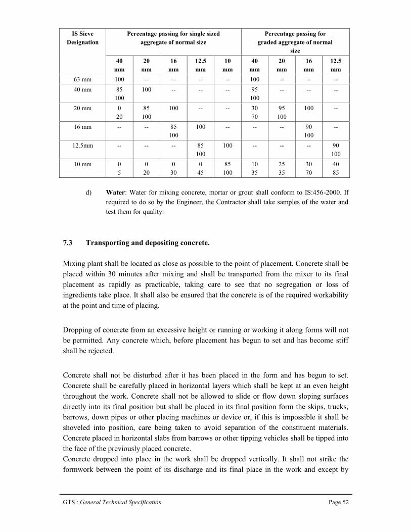
GTS : General Technical Specification Page 52
IS SieveDesignation
Percentage passing for single sizedaggregate of normal size
Percentage passing forgraded aggregate of normal
size40
mm20
mm16
mm12.5mm
10mm
40mm
20mm
16mm
12.5mm
63 mm 100 -- -- -- -- 100 -- -- --40 mm 85
100100 -- -- -- 95
100-- -- --
20 mm 020
85100
100 -- -- 3070
95100
100 --
16 mm -- -- 85100
100 -- -- -- 90100
--
12.5mm -- -- -- 85100
100 -- -- -- 90100
10 mm 05
020
030
045
85100
1035
2535
3070
4085
d) Water: Water for mixing concrete, mortar or grout shall conform to IS:456-2000. If required to do so by the Engineer, the Contractor shall take samples of the water and test them for quality.
7.3 Transporting and depositing concrete.
Mixing plant shall be located as close as possible to the point of placement. Concrete shall be placed within 30 minutes after mixing and shall be transported from the mixer to its final placement as rapidly as practicable, taking care to see that no segregation or loss of ingredients take place. It shall also be ensured that the concrete is of the required workability at the point and time of placing.
Dropping of concrete from an excessive height or running or working it along forms will not be permitted. Any concrete which, before placement has begun to set and has become stiff shall be rejected.
Concrete shall not be disturbed after it has been placed in the form and has begun to set. Concrete shall be carefully placed in horizontal layers which shall be kept at an even height throughout the work. Concrete shall not be allowed to slide or flow down sloping surfaces directly into its final position but shall be placed in its final position form the skips, trucks, barrows, down pipes or other placing machines or device or, if this is impossible it shall be shoveled into position, care being taken to avoid separation of the constituent materials. Concrete placed in horizontal slabs from barrows or other tipping vehicles shall be tipped into the face of the previously placed concrete.Concrete dropped into place in the work shall be dropped vertically. It shall not strike the formwork between the point of its discharge and its final place in the work and except by

GTS : General Technical Specification Page 53
approval of the Engineer, it shall not be dropped freely through a height greater than 1.5 metres. Chutes & Conveyor belts shall be so designed that there is no segregation or loss of mortar and shall be provided with a vertical tapered down pipe or other device to ensure that concrete is discharged vertically into place.
Where a lift of concrete is built up in layers each layer shall be properly merged into the proceeding layer before initial set takes place.
7.4 Quality assurance.
General procedure:
General : In order to achieve the required strength and associated properties of concrete, proper control of the Water/Cement ratio by weight need be enforced. The strength shall be prime consideration and W.C. ratio as prescribed by Engineer in charge shall have to be observed.
Operators : At no time whatsoever will the mixer operator or those supervising or inspecting the works be permitted to alter the quantity of water specified by the Engineer for mixing the concrete. Batching shall be accurate and as specified by the Engineer.
Water/cement ratio : The water/cement ratio will be determined after mix trials by the Contractor in the presence of the Engineer or his representative. If batching is by volume, the Contractor shall be required to fabricate such volumetric batches and water containers as the Engineer may determine and require so as to simulate the ideals of the trial mix without recourse to assessments by site staff and workmen.
Weighing : The Contractor shall make available always a weighing machine if so required, guaranteed by the Contractor for its accuracy, for weighing cement and batches of aggregate as and when the Engineer or his representative or his assistant may require. The machine shall be capable of weighing upto 75kilograms and shall be accurate to half (0.5) kilogram.
Compaction : All concrete shall be thoroughly compacted and fully worked round the reinforcement by vibration just sufficiently so that the appearance of laitance is kept to a minimum and in such manner as directed by the Engineer’s Representative. Under no circumstances shall concrete be compacted by trowels or the like.Transport and placing : Fresh concrete from the mixer shall be transported where required by the quickest and most efficient means so as to prevent pre-set or segregation or any loss of ingredients and shall maintain required workability. Any laitance from previous mixes shall be removed.
GTS : General Technical Specification Page 54
7.5 Sampling, testing and storage of materials.
Samples of aggregates for mix design and determination of suitability shall be taken under the supervision of Engineer and delivered to the laboratory well in advance of the scheduled placing of concrete. Records of tests made on proposed aggregates and on concrete made from this source of aggregates shall be furnished to the Engineer in advance of the work for use in determining aggregate suitability. The cost of all such tests, sampling etc. shall be borne by the Contractor.
Materials shall be tested as hereinafter specified and unless specified otherwise, all sampling and testing shall be performed by testing laboratory approved by employer at the contractor’s
expense.
Cement : Cement shall, whether supplied by the employer or not, comply with the requirements of IS:8041, IS:455, IS:8043, IS:6909, IS:1489, IS:12269. The testing laboratory at the discretion by the Engineer, shall perform such tests as are deemed necessary. Cement bags or bulk silos shall be tagged for identification at location of sampling. Tests will include tensile tests and weighing the cement supply to check for net weight received at site and used in the works.
On arrival at site, cement shall be stored in weatherproof silos designed for the purpose or in dry weather-tight and properly ventilated structures with floors raised 15 to 20cm above ground level, 30cm away from walls and with adequate provision to prevent absorption of moisture or flooding. All storage facilities shall be subject to approval by the Engineer and shall be such as to permit easy access for inspection and identification. Each consignment ofcement shall be kept separately and the Contractor shall use the consignments in the order in which they are received. Any cement in drums or bags, which have been opened, shall be used immediately. Different types of cement shall be kept in clearly marked separate storage facilities. Not more than 15 bags shall be stacked vertically in one pile. Cement shall be stored in double locking arrangement, so that cement transactions can be with the knowledge of supervisory staff. Daily account of cement shall be maintained by the Contractor in the prescribed register and shall be made available to inspecting authorities for store verification.
The Contractor shall provide from each consignment of cement delivered to the site such samples as the Engineer may require for testing. Any cement which is, in the opinion of the Engineer, lumpy or partially set shall be rejected and the Contractor shall promptly remove such cement from the site.
GTS : General Technical Specification Page 55
Cement which has been stored on the site for more than ninety (90) days and cement which in the opinion of the Engineer is of doubtful quality shall not be used in the works until it has been retested and test sheets showing that it complies in all respects with the relevant standard have been delivered to the Engineer.
Water for concrete mixing & curing : Water shall be clean, clear and free from injurious quantities of salt, traces of oil, acids, alkalies, organic matter and other deleterious materials. The sources of water shall be approved by the Engineer and the containers for conveyance; storage and handling shall be clean. If necessary, standard cement tests shall be conducted using the water intended to be used, in comparison with those adding distilled water to check quality of water.
Water shall meet the requirement of 4.3 of IS:456-2000. Generally potable water is fit for mixing and curing.
Aggregates: Aggregate will be tested before and after concrete mix is established and whenever character or source of material is changed. Tests will include a sieve analysis to determine conformity with limits of gradation.
Samples of aggregates 50 kg. in weight will be taken by the contractor at source of supply and submitted to the Engineer before placing orders. These samples if approved shall remain preserved in the Engineer’s care for reference and the type of aggregate used in the works may not be altered without Engineer’s prior approval.
Aggregate shall be obtained from an approved source and shall conform to the requirements of IS:383.
For the aggregate, grading in table of IS:383-1970 shall be applicable. Aggregate shall not be flaky or elongated particles, defined as particles having a maximum dimension greater than five times the minimum dimension. Aggregate shall have water absorption not exceeding two percent when tested in accordance with IS 383.The contractor shall sample and carry out analysis in the presence of the Engineer’s
representative, or the fine aggregate and each nominal size of coarse aggregate in use employing the methods described in IS:383 and 2386 at least once in each week when concreting is in progress and such more frequent intervals as the Engineer may require. The grading of all aggregates shall be within the respective limits specified in the codes. For aggregates, which vary more than the approved fineness modulus, the Engineer may instruct
GTS : General Technical Specification Page 56
the contractor to alter the relative proportions of the aggregate in the mix to allow for such difference, or may require further trial mixes.
Storage of aggregates shall be provided at each point where concrete is made such that each nominal size of coarse aggregate and the fine aggregate shall be kept separated at all times. Contamination of the aggregates by the ground or other foreign matter shall be effectively prevented at all times, and each heap of aggregate shall be capable of draining freely. The contractor shall ensure that graded coarse aggregates are dumped, stored and removed from store in manner that does not cause segregation.
Coarse aggregate shall be piled in layers not exceeding 1.2m in height to prevent coning or segregation. The aggregates must be of specified quality not only at the time of receiving at site but more so as the time of loading into mixer.
Wet fine aggregate shall not be used until, in the opinion of the Engineer, it has drained to a constant and uniform moisture content, unless the contractor with the knowledge of the Engineer measures the moisture content of fine aggregate and adds water in each batch of concrete mixed to allow for the water contained in the fine aggregate.
7.6 Mix design.
Mix design is normally a prerequisite to any concreting job and will be required on all major works. If so required, an approved testing laboratory shall, at the Contractor’s expense,
design a mix for each class of concrete and shall submit full details of the mix designs to the Engineer for his approval. The Engineer’s representative and the contractor shall clearly code
each approved mix with a number and date, and file all details for identifying and reproducing exactly the same mix.
General : Each mix design shall be such that the aggregate shall comprise fine aggregate and coarse aggregate of the size specified and the combined aggregate grading shall be continuous. Aggregate shall be calculated by weight, and batching procedures shall be
GTS : General Technical Specification Page 57
established. The cement content by weight shall not be outside the minimum and maximum limits calculated from the minimum and maximum dry aggregate to cement ratios specified. The mixes shall be designed to produce average concrete cube strength at twenty eighth day after manufacture not less than the trail mix test strength specified. The water/cement ratio shall be in the region of 0.45 to 0.55 and shall never exceed 0.60.
Preliminary Mix : The proportions of cement, aggregate and water determined by the Contractor in his mix design shall be used in preliminary mix of concrete made and tested for strength and workability under laboratory conditions observing the appropriate requirements. These preliminary mixes shall be repeated with adjusted proportions as necessary until concrete mixes meeting the requirements of the preliminary and trial mix tests specified and with the workability defined herein have been produced. If at any time during construction of the works, the source of cement or aggregates is changed, or the grading of the aggregate alters, then further preliminary mixes shall be undertaken.
Trials : After the Engineer’s approval of the preliminary concrete mix design for each class
of concrete and during or following the carrying out of the preliminary tests, the contractor shall prepare a trial mix of each class in the presence of the Engineer. The trial mixes shall be mixed for the same time and handled by means of the same plant that the contractor propose to use in the works. The proportion of cement, aggregates and water shall be carefully determined by weight in accordance with the approved mix design (or modified mix design after preliminary tests) and sieve analyses shall be made, by approved methods of the find aggregate and each nominal size of coarse aggregate used.
Admixtures : Admixtures shall mean material added to the concrete materials during mixing for the purpose of altering the properties of normal concrete mixes. If the Contractor wishes to use admixtures, otherwise than as expressly ordered by the Engineer, he shall first obtain the Engineer’s written permission. The methods of use and the quantities of admixture used
shall be subject to the Engineer’s approval, which approval or otherwise shall in no way limit the contractor’s obligations under the contract to produce concrete with the specified strength
and workability. Concrete of any class containing an admixture shall be separately designed and have separate preliminary tests and trial mixes made and tested for approval by the Engineer as if it were a separate class of concrete.
Waiver of mix design and weigh batching : On certain works, the Engineer may waive the requirement of designing mixes and may allow the use of established nominal mix proportion, provided always that preliminary trials are made to establish the volumetric batching procedure and mix strengths. The Contractor will ensure that any established
GTS : General Technical Specification Page 58
procedure approved by the Engineer is strictly adhered to, so as to achieve consistent strength, durability and economy of the concrete while ensuring approved workability of the mix. Any waiver of mix design or weigh batching will not relieve the Contractor of his obligations to consistently produce concrete of the specified and approved strength and durability as determined by works tests. However in any particular work/part of work, the Engineer may decide to adopt mix design (mix) concrete.
Workability : The workability of each class of concrete shall be such that satisfactory compaction can be obtained when the concrete is placed and vibrated in the works. There shall be no tendency to segregate when it is handled, transported and compacted by the methods, which the Contractor proposes to use when handling, transporting and compacting that class of concrete in the works.
Grades of concrete : The concrete shall be in grades designed in Table 2 IS:456- 2000.
Concrete mix design : Procedure for designing concrete mixes shall be as per IS:10262-82. “Recommended guidelines for concrete mix design”.
7.7 Batching.
Cement : All cement used in making concrete shall be measured by weight either with an approved weighing machine or by making the size of each batch of concrete such as to require an integral number of complete bags of cement of weight consistent with the requirements of cl 9 of IS:12269-1987. In case of ordinary mixes, the cement bag shall be taken to be 50 kg. (35 litres).
Aggregate : The find and coarse aggregate shall be measured separately either by volume in gauge boxes or by weight using machines with weigh batching attachments. For high grade concrete, the fine aggregate shall be measured singly or cumulatively by weight. The Engineer will rule on this requirement.
Gauge Boxes : Gauge boxes shall be soundly constructed by the Contractor, with the approval of the Engineer and shall be of timber or of steel to contain exactly the volume of the various aggregates required for one batch of each mix. Each gauge shall be clearly marked with the mix code and the aggregate for which it is intended. When calculating the size of the gauge box for fine aggregate, allowance shall be made for the bulking of the fine aggregate due to the average amount of moisture contained in the stockpiles on the site. Before the Contractor shall put any gauge box into use on the site, he shall obtain the approval of the Engineer of the size and construction of such gauge box.
GTS : General Technical Specification Page 59
Water container : Containers for measuring water shall be soundly constructed of metal to contain the exact quantity of water required for a batch of mix, due allowance having been made for the moisture content of the aggregates, or such fractions of the quantity as are approved by the Engineer. Containers shall have spouts, the pill levels of which determine the quantity. Fixed containers shall be elevated and have overflow pipes, which determine the quantity held in the container, and shall have an outlet valve and hose fixed to the bottom of the container. Before any container is put into use, the approval of the Engineer shall be obtained.
Weigh-batching : Weigh batching machines shall provide facilities for the accurate control and measurement of the materials either singly or cumulatively and shall be capable of immediate adjustment by operators in order to permit variations if ordered by the Engineer. All weight dials shall be easily visible from the place at which filling and emptying of the hoppers are controlled.
Addition of water and mixing :
Water : The addition of water to a mixer shall be controlled such that between five and ten percent of the water enters the mixer before the cement and aggregate and a further five to ten percent of water enters the mixer after the said materials have been batched. The remainder of the water shall be added at a uniform rate with the said materials. The water-measuring device shall also be readily adjustable so that the quantity of water added to the mixer can, if necessary in the opinion of the witnessing Engineer’s representative be varied. The natural moisture contents of the aggregates shall be determined before the commencement of concreting or at such intervals as may be necessary or as required by the Engineer. The Contractor shall make due allowance for the water contained in the aggregate when determining in consultation with the Engineer’s representative, the quantity of water to be
added to each mix, and shall adjust the amount of water added to each mix to maintain consistently the approved water/cement ratio of the mixed concrete. All important concrete shall be machine mixed to give complete coating of cement mortar on each coarse aggregate particle and to produce uniform coloured concrete with uniform distribution of materials. The mixer shall be run minimum 1½ minutes. In case, for a minor job, hand mixing is permitted by the Engineer, it shall be done on smooth watertight platform not allowing the added water to flow out. The fine aggregate shall be spread in uniform thickness layer over which cement as required shall be placed and they shall be mixed thoroughly to give dry mortar.
Water is then added gradually in required proportion, turning the mass, to give desired consistency mortar. The required quantity of coarse aggregate is then placed on mixing platform, wetted and mortar added. The entire mass is turned and returned to give uniform

GTS : General Technical Specification Page 60
concrete of required consistency. 5% additional cement shall be used for hand mixed concrete.
Admixtures : Any admixtures approved by the Engineer, which may be used, shall be measured separately in calibrated dispensers and shall be added to the mixture together with the water.
Uniformity of mix : Concrete shall be mixed in batches in plant capable of mixing the aggregates, cement and water (including admixtures, if any) into a mixture uniform in colour and consistency and of discharging the mixture without segregation.
Contractor’s returns : The contractor shall render to the Engineer, daily return for each class of concrete of the number of batches mixed, and total volume of concrete placed, thenumber of batches wasted or rejected and the weight of cement used. In case of ordinary mixes, where permitted, the cement bags consumed for quantities of various classes of concrete shall be furnished. In addition daily details of time of starting concrete, closure, no. of batches through mixer, W.C. ratio, slump, date of striking form works etc. shall be maintained. This day-to-day record shall be authenticated by responsible supervisory staff.
Plant and equipment generally : All mixing and batching plants boxes, containers and other equipment shall be maintained free of defects or of set concrete or cement and shall be cleaned before commencing mixing. At such intervals as may be directed by the Engineer, the contractor shall provide weights, containers and equipment necessary for testing the accuracy of the weighting plant, water measuring plant and admixture dispenser.
7.8 Concreting.
Preparation : The Contractor shall clear from the surface of the foundations or previously placed concrete all oil, loose fragments of rock, earth, mud, timber and any other foreign matter and shall clear standing water and wash the surface of a previous lift of concrete to the satisfaction of the Engineer.
Laitance: Where laitance on a lift of concrete is evident or if a substantial bond between this lift or bay or concrete and the next is required, in the opinion of the Engineer’s representative,
the Contractor shall have the surface wire brushed after initial set of the concrete or have it bush-hammered at no extra cost to the employer. Any reinforcing bars covered in laitance shall be wire brushed to clean the surface of the metal.

GTS : General Technical Specification Page 61
Blinding: The formation surfaces on which concrete is to be placed shall be covered with either blinding concrete not less than 75mm thick, or waterproof, building paper, or polythene sheeting immediately after completion of the final trimming of the excavation.
7.9 Inspection.
Concrete shall not be placed until the Engineer has inspected the formwork and the reinforcing steel, and taken necessary measurements of the latter, and has approved the surface upon which the concrete is to be placed.
Transporting:
Fresh concrete shall be transported from the mixer to its place in the works as quickly and as efficiently as possible by methods, which will prevent pre-set or segregation. If segregation has nevertheless occurred in any instance, the materials shall be remixed or discarded at the opinion of the Engineer.
Placing:
Fresh concrete shall be placed and compacted before initial set has occurred and in any event, not later than thirty minutes from the time of mixing. Concrete shall be carefully placed in horizontal layers which shall not be allowed to slide or flow down sloping surfaces but shall be placed in its final position from skips, or similar devices. If this is impracticable, it shall be shoveled into position care being taken to avoid segregation. No concrete shall be dropped more than 1.5m. If greater drops are necessary approved chutes may be used. If the concrete abuts against earth or any other material liable to become loose or to slip, care shall be taken to avoid falls of materials on the surface of the wet concrete.
As far as possible concrete for any particular portion shall be done in one continuous operation leaving construction joints, if specified by drawing.
Before commencing subsequent concrete on the one left incomplete, all the loose particles, laitance etc. shall be removed and surface shall be covered with thick cement slurry. The concrete compacted manually shall be laid in layers not more than 15 to 20cm. The successive layer shall follow within 30 minutes or earlier.

GTS : General Technical Specification Page 62
7.10 Compaction.
All concrete placed in-situ shall be compacted with power driven or pneumatic internal type vibrators unless otherwise approved by the Engineer in writing, and shall be supplemented by hand spading and tamping where required. Vibrating by screed type vibrators may be used for thin slabs. There shall be sufficient and spare vibrators of adequate capacity to compact the work in hand.
Vibration :
Vibrators shall be inserted into the uncompacted concrete vertically and at regular intervals. Where the uncompacted concrete is in a layer above freshly compacted concrete, the vibrator shall be allowed to penetrate vertically for about 75mm into the previous freshly compacted layer. The vibrators shall not be allowed to come into contact with the reinforcement of formwork nor shall they be withdrawn quickly from the mass of concrete but shall be drawn back slowly while in motion so as to leave no voids. Internal type vibrators shall not be placed in the concrete in any arbitrary manner nor shall concrete be moved from one part of the work to another by means of the vibrators. The vibrators shall have minimum 3600 (preferably 5000) impulses per minute.
Duration:
The duration of vibration shall be limited to that required to produce satisfactory compaction of the concrete without causing segregation. Vibration shall on no account be continued after the appearance of water or grout on the surface.
Hand compaction:
This shall be permitted exceptionally for small jobs by the Engineer. In such cases, compaction shall be attained by means of rodding, tamping, ramming and slicing with suitable tools. The thickness of concrete layers will also be suitably reduced when hand compaction is resorted to.7.11 Under water concreting.
No concrete shall be placed in water without the Engineer’s written permission, which may
only be granted if in his opinion it is not practicable to place the concrete in the dry. Concrete shall not be placed in running water nor shall concrete be allowed to fall through water. Any water entering the area where concrete is being placed shall, at the contractor’s expense, be
kept clear of the concreting works. If under water concreting is permitted, the specified mix of concrete shall be strengthened by increasing the cement content by atleast 10.0% and
GTS : General Technical Specification Page 63
reducing the water/cement ratio to no more than 0.45, and the placing shall be only through a tiemie approved by the Engineer. The volume or mass of the coarse aggregate shall not be less than 1 ½ times not more than twice that of the fine aggregate. The material shall be so proportioned as to produce a concrete having a slump of not less than 100mm and not more than 180mm.
7.12 Curing.
All concrete shall be protected from the effects of sunshine, rain, running water or mechanical damage and cured by covering with jute, hessian or similar absorbent material kept constantly wet or a layer of sand kept covered with water is also permissible for a continuous period of fourteen days at least from the date of placement. Should the Contractor fail to water concrete continuously, the Engineer may provide labour and materials required for curing and recover the cost from the contractor.
7.13 Finishing.
Immediately after removal of forms, any undulations, depressions, cavities, honey combing, broken edges or corners, high spots and defects shall be made good and finished with C.M. 1:2, but the necessity of such finishing must be exceptional and total surface requiring finishing shall not exceed 1%. Where concrete surface is to receive plaster, the surface shall be roughened immediately after removal of forms and within a day thereof to secure a hold for the plaster. The rate of concrete is inclusive of this roughening and finishing. Concrete after finishing shall be cured for the full period.
7.14 Joints.
Construction joints:
Construction joints are defined as joints in the concrete introduced for convenience in construction at which special measures are taken at achieve subsequent continuity without provision for further relative movement.
Submittal:
No concreting shall be started until the Engineer has approved the methods of placing, the positions and form of the construction joints and the size of lifts.
Jointing :
The face of a construction joint shall have all laitance removed and the aggregate exposed prior to the placing of fresh concrete. The laitance shall wherever practicable be removed by
GTS : General Technical Specification Page 64
spraying the concrete surface with water under pressure and brushing whilst the concrete is still green. Where the laitance cannot be removed whilst the concrete is green, the whole of the concrete surface forming part of the joint shall be hacked to expose the aggregate. Where aggregate is damaged during hacking, it shall be removed from the concrete face by further hacking. All loose matter shall be removed and the exposed surface thoroughly cleaned by wire brushing, and washing down, and the surface to which fresh concrete is applied shall be clean and damp.
Expansion joints :
Expansion joints are defined as joints intended to accommodate relative movement between adjoining parts of a structure special provision being made where necessary for maintaining the water tightness of the joint.
a. The joint location and type.
1. The Contractor shall comply with the instructions of manufacturers of proprietary jointing materials and shall, if required by the Engineer, demonstrate that the jointing materials can be applied satisfactorily and will last the life of the structure.
2. Flexible water stops shall be fully supported in the formwork, free of nails and clear of reinforcement and other fixtures. Damaged water stops shall be replaced and during concreting care shall be taken to place the concrete so that water stops do not bend or distort.
b. Jointing :
The surface of set concrete shall not be disturbed and concrete shall be placed against the dry finished surface.
1. If ingress of water or corrosive agents in the joint is possible, the steel, where such steel is continued, shall be cleaned and coated with two coats of an approved bituminous paint to a distance not exceeding 10mm.
2. Where specified, the surface of the set concrete shall be painted with two coats of an approved bituminous paint, which shall be allowed to dry before placing new concrete against it. Care shall be taken to prevent paint getting on the water stop, if any.
3. Expansion joints shall be formed by a separating strip of pre-formed compressible imperishable joint filler, to be approved by the Engineer.
7.15 Testing of concrete.

GTS : General Technical Specification Page 65
Sampling and strength test of concrete shall be as per 14 of IS:456-2000.
GTS : General Technical Specification Page 66
Chapter 8
Form Work
8.1 Material.
All formwork for concrete work shall be mostly of MS Plates. The plates shall be free from wrinkles, lumps or other imperfections. Steel plates shall have sufficient thickness to withstand the construction loads and the pressure exerted by the wet concrete as well as vibration during placing of concrete. Normally the thickness shall not be less than 18 gauge for MS Plates.
The formwork may also be constructed of timber, or other approved material. It shall be firmly supported, adequately strutted, braced and tied to withstand the placing and vibrating of concrete and the effects of weather. One copy of the contractors shoring and formwork drawings shall be submitted to the Employer for record purpose only and not for review or approval. Forms, shoring and false work shall be adequate for imposed live and dead loads including equipment and men, height of concrete drop, concrete and foundation pressures and stresses, wind pressures, lateral stability, and other safety factors during construction. The contractor shall be responsible for the calculations and designs for the formwork.
The contractor shall be held solely responsible for any failure and for the safety of work and workmen. He shall pay necessary compensation, if need be, for damages to work, property and injuries to persons. The scaffolding, hoisting arrangements and ladders shall have easy approach to work spot and afford easy inspection.
All formwork shall be fabricated in compliance with the best modern practice, so that the finished surface is even, unblemished free of fins and true to line, level and shape as shown in the drawings. The forms shall comply with the requirements of IS: 456.
8.2 Arrangements.
All formwork shall conform to the shape, lines, dimensions as shown on the plans of the concrete members. the formwork shall include all wedging, bracing, the rod, clamps, stop off boards and other devices necessary to mould the concrete to the desired shape. The formwork shall be constructed as to remain sufficiently rigid during the placing and compacting of the concrete and shall withstand the necessary pressure, ramming and vibrations without any deflection from the prescribed lines and curves. It shall be properly

GTS : General Technical Specification Page 67
strutted and braced in at least two directions. It shall be sufficiently tight to prevent loss of liquid slurry from the concrete. It shall be strongly and firmly erected. The moulds shall be free from holes, open joints, and other imperfections. The formwork shall be so arranged as to permit easy erection initially and easy removal without jarring or disturbing the concrete finally. Wedges and clamps shall be used wherever practicable instead of nails.
Where the depth of formwork exceeds 1.5 metres, the Contractors shall keep one side partly open, from which the concrete could be placed and the planking on the open side could be raised as the work proceeds. This will avoid segregation of material in concrete and also facilitate its proper vibration.
Before concrete is placed, all rubbish shall be removed from the interior of the form and the surfaces of the formwork in contact with concrete shall be cleaned and thoroughly wetted. The inside surface of the formwork shall be treated with a coat of lime, oil or any other material approved by the Engineer. Care shall be taken to see that the above approved composition is kept out of contact with the reinforcement. The slab centering shall be covered with “Double Wax” water proofing paper or tar paper or polythene sheet as directed by the
Engineer.
Where no special finish is desired and where form finish is acceptable, the formwork may be prepared out of water proof black board, which shall give a good finish to the concrete surface and thus there will be no necessity of providing cement plaster finish. For work, which are of repetitive nature, such as column footings, pedestals for pipes, pedestal footings; the formwork shall be fabricated out of steel plates and structurals to obtain uniform finish throughout the work. In all cases the formwork shall be inspected and approved by the Engineer, before any concreting is started. The contractor shall, however, be solely responsible for the proper design, adequacy and stability of the formwork. If at any time, in the opinion of the Engineer, the formwork provided is not considered sufficiently rigid and / or is defective, the contractor shall improve or strengthen the same in such manner as the Engineer may direct. In no circumstances shall form be struck off until the concrete attains adequate strength as required or without obtaining permission of the Engineer. All formwork shall be removed without such shock or vibration as would damage the concrete. Before the soffit and the struts are removed, the concrete surface shall be exposed where necessary in order to ascertain that the concrete has hardened sufficiently. The responsibility for the removal of the formwork whether whole or part, shall rest, entirely with the Contractor who must nevertheless be guided by the opinion of the Engineer in this regard. The work of striking and the removal of formwork shall be conducted in the presence of the Engineer and under personal supervision of a competent foreman in the employment of the contractor.8.3 Removal of Forms and Shoring.
GTS : General Technical Specification Page 68
Formwork shall be so designed as to permit easy removal without resorting to hammering or levering against the surface of the concrete. The periods of time elapsing between the placing of the concrete and the sticking of the formwork shall be as approved by the Engineer after consideration of the loads likely to be imposed on the concrete and shall be in any case be not less than the periods shown below, depending on the ambient temperature.
1. Vertical surfaces of wall 1 day2. Columns & vertical sides of beams 2 days3. Slab bottoms with props left under 7 days4. Beam bottom with prop left under 7 days5. Removal of props under slabs
Span upto 4.5 m 7 daysSpan over 4.5 m 14 days
6. Removal of props to beam and archesSpan upto 6.0 m 14 daysSpan over 6.0 m 21 days
Sequence of striking formwork shall be approved by the Engineer.
Not withstanding the foregoing, the contractor shall be held responsible for any damage arising from removal of formwork before the structure is capable of carrying its own weight and any incidental loading. The contractor shall be wholly responsible for repairing or reconstruction as directed by the Engineer the section of the works so affected.
Shoring and False work Removal :
In retaining wall construction shoring and false work shall not be removed until 21 days after concrete placement or until concrete has attained at least 90 percent of the 28 days design compressive strength as demonstrated by control test cylinders, whichever is earlier.
Restriction :
Construction equipment, or permanent loads shall not be imposed on columns, supported slabs, or supported beams until concrete has attained the 28 days design compressive strength as demonstrated by control test cylinders.
GTS : General Technical Specification Page 69
Concrete curing during removals:
Concrete shall be thoroughly wetted as soon as forms are first loosened and shall be kept wet during the removal operations and until curing media or sacking is applied. Potable water supply with hoses or buckets shall be ready at each removal location before removal operations are commenced.
8.4 Surface treatment & finish.
When the formwork is struck, all the faces of concrete shall be smooth and sound, free from voids and air holes. Any roughness or irregularity on the exposed surfaces shall be immediately filled up while the concrete is still green with cement grout, cement wash and/or 1:1 mortar properly trowelled and finished. Such patching of the concrete face shall be carried only with the permission of the Engineer. If the concrete is found honey-combed, the honeycombed portion and whatever surrounding concrete that may be considered unsatisfactory by the Engineer shall be dismantled and fresh concrete of proper quality shall be provided at contractor’s cost.

GTS : General Technical Specification Page 70
Chapter : 9
Reinforcement
9.1 General.
Reinforcement shall be either plain round mild steel bars Grade I as per IS:432 (Part-I) or medium tensile steel bars as per IS:432 (Part-I) or high strength deformed bars as per IS:1786. Wire mesh or fabric shall be in accordance with IS:1566. Substitution of reinforcement will not be permitted except upon written approval from the Engineer.
9.2 Storage.
The reinforcement shall not be kept in direct contact with the ground but stacked on top of an arrangement of timber sleepers or the like. If the reinforcing rods have to be stored for a long duration, they shall be coated with cement wash before stacking and/or be kept under cover or stored as directed by the Engineer. Fabricated reinforcement shall be carefully stored to prevent damage, distortion, corrosion and deterioration.
9.3 Quality.
a. All steel shall be of Grade I quality unless specifically permitted by the Engineer. No re-rolled material will be accepted. If requested by the Engineer, the Contractor shall submit the manufacturer’s test certificate for the steel. Random tests on steel supplied by the
contractor may be performed by the Engineer as per relevant Indian Standards. All costs incidental to such tests shall be at the contractor’s expense. Steel not conforming to
specifications shall be rejected.
b. All reinforcements shall be clean, free from grease, oil, paint, dirt, loose mill scale, loose rust, dust, bituminous material or any other substances that will destroy or reduce the bond. All rods shall be thoroughly cleaned before being fabricated. Pitted and defective rods shall not be used. No welding of rods to obtain continuity shall be allowed unless approved by the Engineer. If welding is approved, the work shall be carried out as per IS:2751 according to the best modern practices and as directed by the Engineer. In all cases of important connections, tests shall be made to prove that the joints are of full strength of bars welded. Special precautions, as specified by the Engineer, shall be taken in the welding of cold worked reinforcing bars and bars other than mid steel.

GTS : General Technical Specification Page 71
9.4 Submittal of drawings and samples.
Drawings:
The contractor will furnish detailed drawings of reinforced concrete works for approval by Engineer. Working drawings and bar bending schedules shall be prepared by the Contractor from the drawings approved by the Engineer.
Samples:
At least one month in advance of placing an order by him, the contractor shall submit four samples of reinforcing bars which he intends ordering in case, the steel is to be supplied by the contractor.
The samples shall conform to IS: 10790 Part 2-1984. The Engineer may carry out any test he may require to satisfy that the steel to be brought by the contractor complies with the test Specifications.
9.5 Laps and Splices.
Laps and splices for reinforcement shall be as per IS: 456-2000. Splices in adjacent bars shall be staggered and the locations of all splices, except those specified on the approved drawings, shall be only as approved by the Engineer. The bars shall not be lapped unless the length required exceeds the maximum available lengths of bars at site.
9.6 Dowels.
Where and as designated, steel bar dowels shall be provided for anchorage to previously cast concrete.
For anchorage to existing construction, an approved non-shrink epoxy type grout or approved bolting devices shall be used.
9.7 Bending.
a. Reinforcement bars supplied bent or in coils, shall be straightened before they are cut to size. Straightening of bars shall be done cold and without damaging the bars.
GTS : General Technical Specification Page 72
b. All bars shall be accurately bent according to the sizes and shapes. They shall be bent gradually by machine or other approved means. Reinforcing bars shall not be straightened and in a manner that will injure the material; bars containing cracks or splits shall be rejected. They shall be bend cold, except bars or over 25mm in diameter which may be bent hot if specifically approved by the Engineer. Bars, which depend for their strength on cold working, shall not be bent hot. Bars bent hot shall not be treated beyond cherry red colour (not exceeding 845ºC) and after bending shall be allowed to cool slowly without quenching. Bars incorrectly bent shall be used only if the means used for straightening and rebending be such as shall not, in the opinion of the Engineer, injure the material. No reinforcement shall bebent when in position in the work without approval, whether or not it is partially embedded in hardened concrete. Bars having kinks or bends other than those required by design shall not be used.
9.8 Fixing.
Reinforcement shall be accurately fixed by any approved means and maintained in the correct position by the use of blocks, spacers and chairs, as per IS:2502, to prevent displacement during placing and compaction of concrete. Bars intended to be in contact at crossing points shall be securely bound together at all such points with number 16 gauge annealed soft iron wire. The vertical distances required between successive layers of bars in beams or similar members shall be maintained by the provision of mild steel spacer bars at such intervals that the main bars do no perceptibly sag between adjacent spacer bars.
The contractor shall ensure that all reinforcing bars are thoroughly wire brushed and cleaned free of loose mill scale, loose rust, coats and paints, oils, mud or other coating.
Mesh reinforcement, where specified shall conform to IS:1566-1982.
Binding wire shall be annealed wire conforming to IS:280.
9.9 Cover.
Unless indicated otherwise, clear concrete cover for reinforcement (exclusive of plaster or other decorative finish) shall be as follows:
(i) At each end of a reinforcement bar, not less than 25mm nor less than twice the diameter of the bar.
GTS : General Technical Specification Page 73
(ii) For a longitudinal reinforcing bar in a column not less than 40mm, nor less than the diameter of the bar. In case of columns of minimum dimension of 20cm or under with reinforcing bars of 12mm and less in dia. a cover of 25mm may be used.
(iii) For longitudinal reinforcing bars in a beam, not less than 25mm nor less than the diameter of the bar.
(iv) For tensile, compressive, shear or other reinforcement in a slab, or wall, not less than 15mm, nor less than the diameter of such reinforcement.
(v) For any other reinforcement, not less than 15mm, nor less than the diameter of such reinforcement.
(vi) For footing and other principal structural members in which the concrete is poured on a layer of lean concrete, the bottom cover shall be minimum of 50mm.
(vii) For concrete surfaces exposed to the weather or the ground after removal of forms, such as retaining walls, grade beams, footing sides and tops, etc. not less than 50mm for bars larger than 16mm diameter and not less than 40mm for bars 16mm diameter or smaller.
(viii) Increased cover thickness shall be provided for surfaces exposed to the action of harmful chemicals or exposed to earth contaminated by such chemicals acids, alkalis, saline atmosphere, sulphurous smoke etc. and such increase of cover may be between 15mm and 50mm beyond the figures mentioned here as may be specified by the Engineer.
(ix) For liquid retaining structures, the minimum cover to all steel shall be 40mm or the diameter of the main bar, whichever is greater. In the presence of soils and waters of a corrosive character, the cover shall be increased by 10mm.
(x) The correct cover shall be maintained by cement mortar cubes or other approved means. Reinforcement for footing, grade beams and slabs on sub grade shall be supported on precast concrete blocks as approved by the Engineer. The use of pebbles or stones shall not be permitted.
(xi) The 28 day crushing strength of cement mortar cubes/precast concrete cover blocks shall be at least equal to the specified strength of concrete in which these cubes/blocks are embedded.
(xii) The minimum clear distance between reinforcing bars shall be in accordance with IS:456.
9.10 Inspection.
GTS : General Technical Specification Page 74
All continuous inspections shall be performed by the engineer’s representative. Erected and
secured reinforcement shall be inspected and approved by the Engineer prior to placement of concrete.
9.11 Reinforcement Bars Procurement.
Steel reinforcement, such as M.S. bars, High yield strength deformed bars etc., required for the works shall be procured by the contractor. The contractor shall arrange for transport, loading, unloading and storage at the work sites. The contractor should plan the procurement of steel in such a way that at least required quantity of steel of specified sizes is available at site for 3 months period.
Steel brought on site shall be stored in a proper manner as approved by the engineer so as to avoid distortion, deterioration and corrosion. The contractor shall maintain proper registers for the steel account, showing the steel received at site, steel used, and the balance stock on site, to the entire satisfaction of the Engineer. Further, it shall be obligatory on the part of the contractor to submit monthly, quarterly and yearly statements giving the full account of steel on the works and the balance on hand.
9.12 Anti corrosive treatment for reinforcement.
The item covers providing fusion bonded epoxy coating not less than 175 microns thickness and upto 300 microns to reinforcement steels bars of all diameters as per IS Code 13620-1993 for RTS rods for RCC works including testing of coating at plant.

GTS : General Technical Specification Page 75
Chapter : 10
Plastering
10.1 Definitions.
a) The term “plastering” shall cover all types of rough or fair finished plastering,
rendering, floating and setting coat or finishing coat, screed, etc., in mud, lime, cement lime or cement mortar.
b) “Dubbing out” shall mean filling in hollows in the surface of wall and roughly levelling up irregular or out of plumb surfaces, prior to rendering.
c) “Rendering” or “rendering coat” shall mean the plaster coat, which is applied
following the “Dubbing out” or the final coat in case of one coat work.
d) “Floating coat” shall mean the second coat in a three-coat plasterwork, to bring the rendering coat to a true and even surface before the setting or finishing coat is applied.
e) “Setting of finishing coat” shall mean final coat in a two or three coat plaster work.
f) “Thickness of plaster” shall mean the minimum thickness at any point on a surface.
This does not include thickness of dubbing out.
g) The term “even and fair” as referred to finishing of the plastered surface shall mean a
surface finished with a wooden float.
h) The term “even and smooth” as referred to finishing of the plastered surface shall
mean a surface levelled with wooden float and subsequently smoothened with a steel trowel.
10.2 Scaffolding.
GTS : General Technical Specification Page 76
Where possible, independent scaffolding shall be used to obviate the subsequent restoration of masonry in putlog and other breaks in the work. Stage scaffolding shall be provided for ceiling plaster.
10.3 Preparation of Mortar for Plastering.
Materials:
Cement Mortar:
Cement mortar shall have the proportion of cement to sand as mentioned in the item or in the special provisions and shall comply with following:
Cement:
Cement shall conform to IS:12269-1987 Ordinary Portland Cement shall be used. The weight of ordinary Portland cement shall be taken as 50 kg. per bag. The Contractor shall ensure that the cement is of sound and required quality before using it. Any cement, which has deteriorated, caked or which has been damaged shall not be used. The Specifications coveredunder the section brickwork and concrete work shall be applicable in addition.
Water:
Water shall be clean, clear and free from injurious quantities of salt, traces of oil, acids, alkalis, organic matter and other deleterious materials. The sources of water shall be approved by the Engineer and the containers for conveyance; storage and handling shall be clean. If necessary, standard cement tests shall be conducted using the water intended to be used, in comparison with those adding distilled water to check quality of water.
Water shall meet the requirement of 4.3 of IS:456-2000. Generally potable water is fit for mixing and curing.
Fine Aggregate:
All fine aggregate shall conform to IS:38-1970 and relevant portion of IS:515-1959.Sand shall be clean, well graded, hard, strong, durable and of gritty particles free from injurious amounts of dust, clay, kankar nodules, soft or flaky particles, shale, alkali, salts, organic matter loam mica or other deleterious substances and shall be approved by the
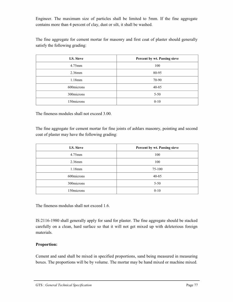
GTS : General Technical Specification Page 77
Engineer. The maximum size of particles shall be limited to 5mm. If the fine aggregate contains more than 4 percent of clay, dust or silt, it shall be washed.
The fine aggregate for cement mortar for masonry and first coat of plaster should generally satisfy the following grading:
I.S. Sieve Percent by wt. Passing sieve
4.75mm 100
2.36mm 80-95
1.18mm 70-90
600microns 40-85
300microns 5-50
150microns 0-10
The fineness modules shall not exceed 3.00.
The fine aggregate for cement mortar for fine joints of ashlars masonry, pointing and second coat of plaster may have the following grading:
I.S. Sieve Percent by wt. Passing sieve
4.75mm 100
2.36mm 100
1.18mm 75-100
600microns 40-85
300microns 5-50
150microns 0-10
The fineness modulus shall not exceed 1.6.
IS:2116-1980 shall generally apply for sand for plaster. The fine aggregate should be stacked carefully on a clean, hard surface so that it will not get mixed up with deleterious foreign materials.
Proportion:
Cement and sand shall be mixed in specified proportions, sand being measured in measuring boxes. The proportions will be by volume. The mortar may be hand mixed or machine mixed.

GTS : General Technical Specification Page 78
Preparation:
In hand mixed mortar, cement and sand in the specified proportions shall be thoroughly mixed dry on a clean impervious platform. Fresh and clean water as specified above shall be added gradually and thoroughly mixed to form a stiff plastic mass of uniform colour so that each particle of sand shall be completely covered with a firm of wet cement.
The water cement ratio may be as under or as directed by the Engineer.
Cement Sand Water - Cement ratio Quantity of water per 50 kg. Of cement
(Litres)1 1 0.25 12.51 1 ½ 0.28 14.01 2 0.30 15.01 1 ½ 0.35 17.51 3 0.40 20.01 4 0.53 26.51 5 0.60 30.01 6 0.70 35.01 8 0.90 45.0
Machine mixed mortar shall be prepared in an approved mixer. Water cement ratio shall be as per hand mixed mortar. The mortar so prepared shall be used within 30 minutes of adding water. The mortar remaining unused after that period, mortar, which has partially hardened or is otherwise damaged shall not be re tempered or remixed. It shall be destroyed or thrown away.
10.4 Preparation of Background for Application of Plaster.
Cleanliness:
All dirt, dust and other foreign matter on masonry and laitance on the concrete surfaces shall be removed by watering and brushing as required. If the background contains soluble salts particularly sulphates, the application of plaster shall be done only after the efflorescence of the salts is complete and the efflorescence is completely removed from the surface.Joints in brickwork, stone masonry and hollow block, masonry shall be raked out to a depth of not less than 10mm as the work proceeds. Local projection in brickwork and masonry beyond the general wall face shall be trimmed off where necessary.
Roughness:
GTS : General Technical Specification Page 79
Smooth surfaces of in-situ concrete walls and ceilings etc. shall be roughened by wire brushing, if it is not hard; and by hacking or bush hammering if it is hard, to provide for proper adhesion. Projecting burrs of mortar because of gaps at joints in shuttering shall be removed. The surface shall be scrubbed clean with wire brushes. In addition concrete surface shall be pock marked with a pointed tool at spacing of about 50mm, the pocks made to be not less than 3mm deep.
Suction Adjustments:
Adequate drying intervals shall be allowed between the erection of masonry and plastering to bring the surface suitable for suction adjustment. High rate of suction makes the plaster weak, porous and friable. The wall shall not be soaked but only damped evenly before applying the plaster. If the surface becomes dry in spots, such areas shall be moistened again to restore uniform suction. Excessive water leads to failure of bond between the plaster and the background.
Evenness:
Any local unevenness must be leveled and projections removed to avoid variance in the thickness of plaster.
Immobility:
Differential movements between the background and the plaster due to moisture change, temperature change, structural settlement, defection, etc. cause cracks. The major part of such movements shall be allowed to set in before the plaster is applied.
10.5 Plastering.
Plastering Generally:
The type and mix of mortar for plastering, the number of coats to be applied, the surface finish of the plaster and the background to which the plaster is to be applied shall be as indicated.The mortar for dubbing out and rendering coat shall be of the same type and mix. Dubbing out may be executed as a separate coat or along with the rendering coat.
Protection:
All existing work and fittings that are likely to be damaged in the application of plastering shall be protected. Care shall be taken to avoid, as far as possible, the splashing of mortar on

GTS : General Technical Specification Page 80
to the finished surfaces such as joinery, paint work and glazing; all such splashes shall be cleaned off immediately.
Screeds 15 x 15cm shall be laid vertically and horizontally not more than 2m apart to serve as guides in bringing the work to an even surface.
Plastering shall be done from top to bottom and care shall be taken to avoid joints in continuous surface.
Maintenance of proper time intervals:
To avoid break down of adhesion between successive coats, drying shrinkage of first coat shall be allowed to be materially completed before a subsequent coat is applied.
All corners, arises, angles, junctions shall be truly vertical or horizontal as the case may be and shall be carefully finished. Rounding or chamfering of corners, arises and junctions shall be carried out with proper templates to the required size. Plastering of cornices, decorative features, etc. shall normally be completed before the finishing coat is applied.
In suspending the work at the end of the day, the plaster shall be cut clean to the line both horizontally and vertically. When recommencing the plastering, the edge of the old work shall be scraped clean and wetted with lime putty or cement slurry before plaster is applied to the adjacent area. Partially set and dried mortar shall not be re tempered for use.
Cleaning of completion:
On completion, all work affected by plastering and pointing shall be left clean, special care shall be taken when removing any set mortar form glass and joinery, etc. to avoid damaging their surface.10.6 One coat plaster work.
Mortar shall be firmly applied to the masonry walls and well pressed into the joints and forcing it into surface depressions to obtain a permanent bond. The plaster shall be laid in a little more than the required thickness and levelled with a wooden float. On concrete walls, rendering shall be dashed on to roughened surface to ensure adequate bond. The dashing of rendering coat shall be done using a strong whipping motion at right angles to the face of walls. The surface shall be finished even and fair. Unless indicated to be finished even and smooth.

GTS : General Technical Specification Page 81
10.7 Two coat plaster work.
First Coat:
The first coat of the specified thickness shall be applied in a manner similar to one coat plasterwork. Before the first coat hardens, the surface of the cement and cement lime plasters shall be scored to provide key for second coat. In case of lime plasters the surface shall be beaten with edges of wooden thapies and close dents shall be made on the surface, to serve as a key to the subsequent coat. The rendering coat shall be kept damp for atleast two days, it shall be allowed to become thoroughly dry.
Second Coat:
Before starting to apply second coat, the surface of the rendering coat shall be damped evenly. The second coat shall be completed to the specified thickness in exactly the same manner as the one coat plaster work.
10.8 Neeru finish.
After applying and finishing the undercoats and before they set, the finishing coat of specially prepared lime putty about 1.5mm thick shall be applied. It shall be well polished with a trowel.
10.9 Sand faced plaster.
After the undercoat of cement and sand mortar 1:4 not less than 10mm thick, has been applied and finished, the final coat of cement and sand mortar 1:4 shall be applied to a thickness not less than 5mm and brought to an even surface with a wooden float. The surface shall then be tapped gently with a wooden float lined with cork to retain a coarse surface texture, care being taken that the tapping is even and uniform.10.10 Curing.
Each coat shall be kept damp continuously for at least two days. Moistening shall commence as soon as the plaster has hardened sufficiently and is not susceptible to injury. The water shall be applied preferably by using a fine fog spray. Soaking of wall shall be avoided and only as much water as can be readily absorbed shall be used. Excessive evaporation on the sunny or wind ward sides of buildings in hot dry weather shall be prevented by hanging matting or gunny bags on the outside of the plaster and keeping them wet.

GTS : General Technical Specification Page 82
After the completion of finishing coat, the plaster shall be kept wet for at least seven days and shall be protected during that period from extremes of temperature and weather.
10.11 Water proofing plaster.
Integral water proofing compound shall be mixed with cement in the proportion indicted by weight. Care shall be taken to ensure waterproofing material gets well and integrally mixed with cement and does not run out separately when water is added.

GTS : General Technical Specification Page 83
Chapter 11
Laying and Jointing of D.I. Pipes
11.1 Transportation.
The transportation of materials to work site and stacking shall be done in such a manner as to cause minimum inconvenience to the traffic and other construction works. Pipes shall be protected during handling against impact, shocks and free fall to avoid cracks and damage. Pipes shall be loaded for transportation is in such a way that they are secured and no movement can take place on the vehicle during transit. The same care shall be taken if pipes are transferred from one vehicle to another, however short the journey may be. The cement mortar lining of pipes that are damaged during transportation is to be repaired by hand application if possible; otherwise it has to be rejected. The decision for rejection shall be taken by the Engineer in charge.
11.2 Unloading of pipes.
Each pipe consignment shall be inventoried and inspected with care upon arrival even though the pipes have been inspected and loaded with care at the factory. Overall examination shall be made during unloading to ensure that the pipes have reached destination in good condition. If there is any sign of rough treatment on the coating, each pipe shall be inspected for damage.
While unloading, pipes shall not be thrown down from the truck to the hard roads. Cranes or mechanical equipment shall be used for unloading the pipes from the truck. If mechanical equipment is not available, care should be taken to unload the pipes on timber skids. Unloading them on timber skids without a steadying rope and thus allowing the pipe to bump hard against one another should not be allowed. In order to avoid damage to the pipes specially to the spigot end, pipe should not be dragged along concrete and similar pavements with hard surfaces. The pipes shall be laid on timber battens and secured with wooden wedges. The pipes shall be stacked with each tier at right angles to the preceding tier.
11.3 Lowering of pipes and fittings.
The pipes shall be lowered cautiously to prevent disturbances of the bed and sides of the trench.

GTS : General Technical Specification Page 84
Proper implements, tools and facilities satisfactory to the Authority shall be provided and used for the safe and convenient execution of the work. All pipes, fittings, valves and hydrants shall be carefully lowered into the trench, piece by piece, by means of a derrick, ropes or other suitable tools or equipment, in such a manner as to prevent damage to pipes materials and protective coatings and linings. Under no circumstances shall pipes materials be dropped or dumped into the trench. Pipes over 300mm diameter shall be handled and lowered into trenches with the help of chain pulley blocks or preferably by cranes. Tripod supports used for this purpose shall be regularly checked to prevent all risks of accidents.
11.4 Cleaning of pipes and fittings.
All lumps, blisters and excess coating material shall be removed from the socket and spigot end of each pipe. The outside of the spigot and the inside of the socket shall be wire-brushed and wiped clean and dry and free from oil and grease before the pipe is laid.
11.5 Laying.
Before lowering the pipe, the trench section shall be got approved from the Engineer in charge. Trenches are to be dug to the specified level / grade. Sufficient cushion shall be provided for protection from surface traffic, future changes in the ground elevation. The width of the trench shall be to the required specifications providing room for pipe laying operation, backfilling, compaction etc., Trenches should be shored and braced when conditions so warrant.
The bottom of the trench shall form a continuous bed for the pipe. Where rock is encountered, trenches shall be dug deeper and then filled and compacted to grade with suitable bedding material. The Contractor shall have to provide and maintain sight rails and boning rods wherever required till the completion of work. The pipe shall be laid in reasonably dry condition and under no circumstances they shall rest on slushy bedding.
The pipes shall be lowered slowly into the trench by means of chain pulley block and tripodstand or with the help of ropes and suitable size of wooden bullies or with the help of cranes. They shall be brought to the required level by giving packing with wooden sleeper pieces and ultimately with well-consolidated hard moorum if required. The chain pulley block and tripod stand must be approved from the Engineer in charge. Under no circumstances pipe shall be allowed to be thrown in the trenches.
At the end of each day, the end of the pipe should be plugged to prevent entry of rodents, foreign substances, water etc.11.6 Support of pipe for nallah/river crossing.
GTS : General Technical Specification Page 85
Venteak piles are proposed for portion of pipeline which crosses the nallah/river or slushy soils. Each pipe shall be supported on a pair of Venteak piles driven upto 3.50m or firmground whichever is met earlier.
One pair of timber piles shall be driven about 150mm behind the shoulder of toe socket and another pair about 750mm in front of the spigot end of the pipe.
The size of timber section to be used for Venteak piles shall be:
100mm x 100mm for pipe sizes upto 300mm150mm x 150mm for pipe sizes above 300mm
A cross piece of section same as that of pile shall be bolted to a pair of piles which have been driven to the required depth.
The level of the cross piece should be such that when the pipe rests on its top, its Invert level coincides with the proposed invert of the pipe.
The pipe shall be aligned for straightness and secured in position by wooden wedges nailed down to the wooden cross piece.
The spigot end of each pipe shall be thoroughly homed in to socket of preceding pipe and jointing made.
The pipe shall be further secured from moving upwards by timber crosspieces bolted to the supporting piles. The section of the crosspiece shall be same as that of pile.
The socket ends of all pipes shall face up hill irrespective of the direction of water flow. Any deviation either in plan or elevation of less than 11 ¼ deg. angle shall usually be effected by laying straight pipes round a flat curve, of such radius that rubber gasket shall not be disturbed in its place.
Wherever new pipes laid are to be jointed with existing pipeline, first pipe laying work of new pipes are to be completed. Jointing of new pipe line with existing pipe line has to be completed within a stipulated time as per the instructions of Engineer in charge to keep the distribution system ready to supply water to the city. No extra payment will be made for this time bound urgent work.11.7 Testing.
GTS : General Technical Specification Page 86
After laying and jointing, the pipeline must be pressure tested to ensure that the pipes and joints are sound enough to withstand the maximum pressure likely to be developed under working conditions. The contractor shall submit for the Engineers approval, details of his proposed methods and programme for testing including details of test equipments and shall arrange for all tests to be witnessed by the Engineer or his representative. The contractor shall provide all things necessary for carrying out testing and cleaning including water pumps, gauges, piped connections, stop ends, and all other temporary works.
Pipelines shall be properly completed and supported before being put under test. No testing will be permitted until ten days after thrust blocks and other holding down works have been completed. In addition to any tests of individual joints or other interim tests which may be specified elsewhere, the contractor shall submit, all parts of the pipelines to a final test. Notwithstanding the foregoing, the contractor may at any stage of construction, carry out such other tests as he considers desirable to check materials and workmanship on the pipeline but this shall not relieve the contractor of his obligations to achieve successful tests under the contract.
All water required for testing and cleaning the pipelines shall be potable water and shall be provided by the contractor at his cost. The test can be carried out by means of a hand pump or a pressure pump.
Pipelines shall be tested in lengths between valve pits or such lengths as the Engineer may direct or permit.
Fittings required for temporarily closing the openings in pipelines to be tested shall be properly designed for this purpose and shall be adequately strutted to withstand the pressure specified.
The completed pipeline may be tested in sections; the length of section should be decided by considering:
(a) The availability of suitable water;(b) The number of joints to be inspected; and(c) The difference in elevation between one part of the pipeline and another.
The maximum length that can be tested in one operation shall be restricted to 500m and minimum length shall be 50m.Where joints are left uncovered until after testing, sufficient materials should be backfilled over the centre of each pipe to prevent movement under the test pressure.
GTS : General Technical Specification Page 87
The contractor shall make his own arrangements to procure necessary equipments, apparatus etc., required for testing and shall provide necessary labour for filling with water the length of pipes to be tested, fixing all apparatus and for carrying on the testing operations until the length of pipe, specials and connections are firmly passed by the Engineer. If the testing apparatus and equipments are available with the employer, they can be hired by the contractor at usual conditions and charges.
The length to be tested shall be provided with two blank flanges fastened on the usual manner by collar bands and bolts to the end pipes or if the length to be tested shall have a sluice valve at each end, such blank flanges may be dispensed with.
The length of pipes to be tested shall first be filled in with water from a higher section of pipes already laid or with clean water obtained from a service connection, as the contractor may arrange with the approval of the Engineer.
Before the actual testing pressure is applied, any air which has logged in the length of pipe to be tested shall be got rid of, by screwing on at the highest part of the length of pipes or temporary air valve, or by opening a temporary stopcock or by other means as the Engineer may direct.
The test pressure shall not be less than 10 kg/cm²
Each pipeline or section thereof, shall be filled with water and all air removed. The pressure in the pipelines shall be raised steadily until the site test pressure is reached in the lowest part of the section. This pressure should be maintained, by pumping if necessary, for a period of not less than 1 hour. The pump should then be disconnected and no further water permitted to enter the pipeline for a period of 1 hour. At the end of this period, the reduced pressure in the pipeline should be measured, the original test pressure restored by pumping and the loss measured by drawing off water from the pipeline until the pressure has fallen to match the reduced pressure previously noted. The loss shall not exceed 0.02 litre per mm diameter per kilometer per 24 hours for each bar of head applied. If the pipeline fails to pass the test, the faults shall be located and repaired and the pipeline retested until it passes the pressure test. All exposed pipe, fittings, valves and joints shall be visually inspected during the tests.If the length of pipeline under test is found to be satisfactory and no leaks or sweating are found at the pipe joints or at the joints of specials and connections, then this length of pipeline will be passed by the Engineer.

GTS : General Technical Specification Page 88
But should any pipe, joint, special or connection be found to sweat or leak, contractor shall make good at his cost such defective joints and the length of pipe line shall be retested until all pipes, joints specials and connections are found to be satisfactory.
After satisfactory test, the contractor shall remove water from the pipeline and clean it after testing at his own cost, without flooding adjoining areas.
Duration of Hydraulic Test:
The test is for 1 hour only. The rate of allowable leakage is given on per day basis. The leakage observed within one hour shall be converted to per day basis and compared with criteria given.
Maximum field test pressure for pipes with flexible joints:
Table : 1 on page 11 of IS:12288 wherever is applicable.
11.8 Interconnection work.
The interconnection work between the existing main and the proposed main to be laid under this contract shall proceed from the new main to the existing main. Before actually proceeding with the interconnection work, the Contractor shall make ready necessary tools and plants required for the work at site, such as pump sets, shoring materials etc. He shall also keep ready at site necessary pipes, jointing materials, specials and valves required for the work. The Contractor shall keep necessary skilled workmen of sufficient strength at site and once the work commenced, the entire interconnection work shall proceed without interruption by engaging labour for carrying out the work on a continuous basis both day and night till the work is completed. The work shall be executed as per programme drawn up by the Engineer and shall be completed within the time ordered by the Engineer, for each individual interconnection. The work shall be carried out under the direction of the Engineer from the beginning to end.
Laying of specials, valves (except straight pipes from the branch of the new main to the connecting point in the existing main) including conveying specials etc. from the stores or site of stacking, excavating, timbering, pumping out water from the trenches, lowering, aligning, jointing specials and valves, cutting the existing mains, dealing with water, inserting the necessary branches, jointing, testing, refilling etc. is included in the item of providing, laying and jointing DI/MS pipes. Any ancillary work either of Temporary or Permanent
GTS : General Technical Specification Page 89
nature required for interconnection and not covered by schedules shall be executed by the Contractor at no extra cost.
11.9 Flanged joints.
Flanged joint should be made by painting the facing of the flange with white lead freely and bolting up evenly on all sides. A thin fibre of lead wool may be very useful in making the joints water tight where facing of the pipes is not true.
When packing must be used, it should be of rubber insertion three ply and of approved thickness. The packing should be of the full diameter of the flange with proper pipe hold and bolt holes cut out evenly on both the inner and outer edges. Where the flange is not full faced, the packing may be of diameter of the packing strip only, proper placing of the packing should be checked before another pipe is jointed on.
11.10 Disinfection of Mains.
Upon completion of a newly laid main or when repairs to existing pipes are made, the main shall be disinfected as directed by the Engineer.
The main shall be flushed prior to disinfection except when the tablet method is used. After initial flushing, the hypochlorite solution shall be applied to the water main with mechanically or electrically powered chemical feed pump designed for feeding chlorine solutions. For small applications, the solution may be fed with a hand pump.
In the case of mains of large diameter, water from the existing distribution system or other approved source shall be made to flow at a constant measured rate into the newly laid pipeline. The water shall receive a dose of chlorine also fed at a constant measured rate. The two rates shall be proportioned so that the concentration in the water entering the pipeline is maintained at not less than 300 mg/l. The chlorine shall be applied continuously and for a sufficient period to develop a solid column of ‘Slug’ of chlorinated water that will, as it
passes along the line, expose all interior surfaces to a concentration of at least 300 mg/l for atleast 3 hours. As the chlorinated water flows through tees and crosses, related valves and hydrants shall be operated so as to disinfect the appurtenances.In the case of newly laid mains in which scrupulous cleanliness has been exercised, the tablet method can be adopted and in this method, the initial flushing is dispensed with. The calcium hypo chlorate tablets, are placed in each section of pipe and also in hydrants, hydrants branches and other appurtenances. The tablets shall be attached by an adhesive and must be at the top of the main. The main shall then be filled with water and the water shall remain in the pipe for atleast 24 hours.
GTS : General Technical Specification Page 90
After the applicable retention period, the heavily chlorinated water shall be flushed from the main until the chlorine concentration in the water leaving the mains is no higher than that generally prevailing in the system or less than 1 mg/l.
After final flushing and before the water main is placed in service, a sample or samples shall be collected from the end of the line and tested for bacteriological quality and shall show the absence of coliform organisms. If the initial disinfection fails to produce satisfactory samples, disinfection shall be repeated until satisfactory samples have been obtained. When the samples are satisfactory, the main may be placed in service.
The contractor is expected to carry out the disinfection work as a part of laying the pipes and his rates for laying the pipes should include the disinfection and other connected works tillthe main is placed in service unless otherwise specified in the schedule.

GTS : General Technical Specification Page 91
Chapter 12
AppurtenancesA. Sluice valves
12.1 General.
All valves shall be double-flanged valves of Indian manufacture and in the size range 50mm to 1000mm conforming to IS: 14846 – 2000 or any other national standard equivalent or higher than the Indian Standards mentioned. The materials used in construction, the design and all other relevant features shall be such that the valves are entirely suitable for use of force mains. Valves shall be of suitable pressure rating which shall not be less than twice the normal operating pressure. The valve shall be fitted with motorise actuator and position indicator for compatibility with proposed automation control and visualization system.
12.2 Design.
The design of the valves will be such that erosion, cavitation, vibration and head loss (in the fully open position) shall be a minimum.
12.3 Sluice valves.
Sluice valves shall generally conform to IS: 14846 - 2000. Valves should close with clockwise rotation of the hand wheel. The direction of closing should be marked on the hand wheel. Valves shall be flanged (flat faced) and drilling shall conform to IS: 1537.
12.4 Materials of Construction.
Body - C.I. to IS: 210 Gr. FG 200Wedge - C.I. to IS: 210 Gr. FG 200Seat Rings - Bronze / SS 304Channel lining - Gun MetalShoe - Gun MetalSpindle - SS A1S1 431
Parameters:
Rating - 10 Bar (PN 1.0)Shop Testing Witnessing:

GTS : General Technical Specification Page 92
Seat leakage test - 10 bar (1.0 M Pa)Body Hydrostatic test - 15 bar (1.5 M Pa)
Back Seat Leakage test - 15 bar (1.5 M Pa)
12.5 Valve bodies.
a. Castings:
The structure of the castings shall be homogeneous and free from non-metallic inclusions and other injurious defects. All surface of casing which are not machined shall be smooth and shall be carefully filed to remove all foundry irregularities.
b. Forgings:
All major stress bearing forgings shall be made to a standard specification, which shall be submitted if required to the Engineer for approval before work is commenced. Forgings shall be subjected to non-destructive tests to detect flaws if any. Forgings shall be heat treated for the relief of residual stresses.
c. Workmanship:
Workmanship and general finish shall be of first class commercial quality and in accordance with best workshop practice.
All similar items of the valve and their component parts shall be completely interchangeable. Spare parts shall be manufactured from the same materials as the originals and shall be accurate and to specified tolerances so that replacements made to manufacturer’s drawings
may be readily installed.
All parts, which can be worn or damaged by dust, shall be totally enclosed in dust proof housings.
d. Protective coating:
Protective coating shall comply with IS: 14846 - 2000.12.6 Lubrication.

GTS : General Technical Specification Page 93
All the points where lubrication is needed, the Contractor shall furnish full details of the method to be employed. The supply of the requisite lubricating equipment and lubricants for commissioning and operating and maintaining the valves shall be furnished.
12.7 Flanges.
Valves of sizes 80mm – 1000mm shall have flat flanges as per relevant IS. The flange-to-flange distances shall be as per IS 14846.
12.8 Jointing Materials.
Each valve shall be supplied under this Contract, with all requisite joint rings, nuts, bolts and washers for making the joints on all the valves to be installed under this Contract. Jointing material between the connecting flanges shall conform to the relevant IS code. Unless otherwise specified bolting used for jointing exposed connections shall be of carbon steel, conforming to IS: 210 Grade 20 Grade B, with galvanized finish.
12.9 Factory Tests.
All the valves shall be tested at the factory for smooth, trouble free operation and operating torque requirements by operating between fully open and fully closed position three times.
The hydrostatic tests shall consists of Closed End Tests where valve is held on both sides. Each valve is subjected to three hydraulic tests.
a. Wedge open and pressure applied for 5 minutes to the whole body of the valve pressure given in Section 19.4.
b. Second Test shall be applied to one face with pressure given in Section 19.4.
c. Third Test shall be similar to second, but pressure applied to the other side of the wedge with same pressure.
For valves having terminal position shall be subjected to open-end test.
B. Air Valves
1. Constructional features.

GTS : General Technical Specification Page 94
Double ball air valves shall be of the kinetic, double orifice type able to release air in small quantities under pressure and in large quantities during filling. They have to allow for large inflow of air during emptying. The type and locations shall be fixed according to the detailed design and after approval by the Engineer in charge. The valves shall have an integrated sluice valve. The possible air velocity (inflow and outflow) must be at least 20 m/s.
Materials of Construction & Pressure Rating:
Body CI to IS Gr. FG 200
Cowl CI to IS Gr. FG 200
Valve seat, nut Leaded tin bronze
Spindle SS. AISI 304
Orifice SS. AISI 304
Ball Seasoned teak wood, covered with neoprene rubber
Ball seat Anti-stick material such as nitrile rubber or equivalent
Pressure Suitable for 16 Kg / sq.cm, Working Pressure.

GTS : General Technical Specification Page 95
Chapter 13
Fixing of Valves
13.1 Fixing of Sluice Valves.
General:
The specification lays down the requirement for lowering, laying and jointing Sluice valves.
Preparation:
The sluice valves and tailpieces shall be examined before laying for cracks and other flaws. Only undamaged S.S. shall be used.
The sluice valve shall be operated and checked before laying. All grit and foreign material shall be removed from the inside before placing. All the four faces shall be thoroughly cleaned and coated with a thin layer of mineral grease. The tightening of gland shall be checked with a pair of inside calipers. Clearance between the top of stuffing box and the underside of the gland shall be uniform on all sides.
Jointing materials:
The Contractor shall provide all the necessary jointing materials such as nuts, bolts, rubber packing, white zinc, jute, lead wool etc. at his cost. All tools and plant required for installation of sluice valve shall be provided by the Contractor at his cost. All the jointing materials shall be got approved from the Engineer in charge before use. The nuts and bolts shall conform to IS: 1364 and the rubber packing shall conform to IS: 638.
Installation:
The sluice valve shall be lowered into trench carefully, so that no part is damaged during lowering operation. If necessary tailpieces shall be fitted with sluice valve first outside the trench and then lowered into the trench.
The rubber packing shall be three ply and of approved thickness. The packing shall be of full diameter of the flange, with necessary holes and the sluice valve bore. It shall be even at both the inner and outer edge. The flange faces shall be thoroughly greased. If flanges are not free the Contractor shall use thin fibres of lead.After placing the packing, nuts and bolts shall be inserted and tightened to make the joint.

GTS : General Technical Specification Page 96
The valve shall be tightly closed being installed to prevent any foreign materials from getting in between the working parts of the valve.
Each flange bolt shall be tightened a little at a time taking care to tighten diametrically opposite bolts alternately.
The sluice valve shall be installed in such a way that spindle shall remain in truly vertical position. The other end of the tailpiece shall be fitted with pipes so that continuous lines canwork. Extra excavation necessary to facilitate the lowering and fixing of sluice valve shall not be paid for.
Testing:
After installation of sluice valve the same is tested to 1 ½ times of its test pressure. The joints of sluice valve shall with stand the test pressure of pipeline.
Defects noticed during test and operation of sluice valve shall be rectified by the Contractor at his own cost, without any extra claim, to the entire satisfaction of the Engineer in charge.
13.2 Fixing of air valves.
General:
The specification placed down requirement for lowering laying and fixing Air Valves.
Preparation:
The air valves and the isolating valves shall be examined before laying for cracks and other flaws. Only undamaged air valve shall be used. The air valves shall be opened and shaken for the air opening below the vulcanite balls on the bronze seats of the balls before fixing. All grid and foreign material shall be removed from the inside before placing. The flanged face shall be thoroughly cleaned and coated with a thin layer of mineral grease. In case of screw down type, the threads shall not be in damaged condition. Jointing Materials:

GTS : General Technical Specification Page 97
The contractor shall provide all the necessary jointing materials, such as nuts, bolts, rubber packing, white zinc jute, lead wool etc. at his cost. All tools and plant required for installation of air valve shall be provided by the contractor at his cost. All the jointing materials shall be got approved from Engineer in charge before use. The nuts and bolts shall conform to IS: 1364 and the rubber packing shall conform to IS: 638.
Installation:
The air valves shall be fixed on a branched flange Tee on the main pipeline. The air valve and isolating sluice valve shall be housed in a chamber.
Testing:
The specification pertaining to sluice valve shall also apply to air valves.
13.3 Fixing of C.I. M.H. Frame and cover in RCC Slab.
General:
The specification includes all requirements of fixing C.I. M.H. frame and cover of specified size and weight in the RCC slab with locking arrangement. For fixing the C.I. M.H. frame and cover of specified size and weight, the frame shall be fixed generally at the time of casting RCC slab with proper anchoring. After fixing the M.H. frame and cover locking arrangement shall be provided as per following unless specified in the wording of the item. The size of the M.S. flat shall be 50mm x 10mm with M.S. bar U shape of 16mm dia. The U shape M.S. bars shall be properly embedded in the RCC roof slab and anchored. The C.I. M.H. frame and cover and the locking arrangement after fixing shall be painted with anticorrosive black paint. The work shall be done to the entire satisfaction of the Engineer in charge.

GTS : General Technical Specification Page 98
Chapter 14
Miscellaneous
14.1 Pressure gauges
Material:
The brief specifications for pressure gauges is as follows:
The pressure gauges shall be of Bourdon type having a range between 0 to 20kg/sq.cm. The diaphragm material should be of 316 SS. Accuracy of the pressure gauge shall be 1% with a dial diameter of 150mm. The case shall be of IP 65, die cast AI. The pressure gauge shall be directly mounted with connection of ½ “ N.P.T.M.
Erection:
The pressure gauges shall be, mounted as near to the process as possible. Impulse tubing/piping length shall be minimum possible. The pressure gauges shall be mounted in a vibration free location. They shall be readily accessible from grade, platform, fixed walkway or fixed ladder and shall be visible from where related equipment is operated.
The pressure gauges shall have one isolating valve and one drain/vent valves for depressuring. The drain/vent valve shall be plugged. The valves used shall be having ½ “NPTF connections and the material shall be ASTM A 216 GR. WCB or ASTM A 105
unless otherwise specified. The trim shall be AISI 410 unless otherwise specified. All connection shall be made using thread seals preferably PTFE tape. Right tools shall be used and any limits regarding torque for tightening shall be strictly adhered to. Impulse piping shall be done using ½“ o.d seamless annealed ss tubing to ASTM A 269 GR.TP -136 L with minimum wall thickness of 1.65mm. Compression fittings shall be used. The impulse piping must be supported by an angle of channel and strapped at every meter length. The angle/channel itself must be supported by welding it to some structure. The pressure gauge shall be covered with box.

GTS : General Technical Specification Page 99
14.2 Electromagnetic flow meter.
Electromagnetic flow meter shall measure and indicate both instantaneous and cumulative flow and provided with flanged ends. Measurement flow shall be independent of pressure, temperature, density and viscosity. It shall be compatible for short inlet outlet connections and also for free pipe cross section. There should not be any additional pressure losses in the pipeline due to installation of electromagnetic flow meters. The calibration of flow meters shall be direct comparison of volume with high accuracy of up to ± 0.2% of actual value. Electromagnetic flow meter shall be complied with IP 68 protection class for submerged operations.
DTS : Detail Tender Specification Page 100
Chapter : 15
Technical specification for laying of clear water feeder mains and replacement of existing damaged CI feeder mains with DI pipes from
the treatment plant to different Zonal reservoirs under Tura Phase-I & II w.s.s
The Intent of this Tender is distribute to convey the treated clear water from clear water from clear water reservoirs of treatment plant of Tura Phase-I and Phase-II w.s.s. to different Zonal reservoirs and also to replace old existing damaged feeder mains with new D.I feeder mains . 15.1 INTRODUCTION The clear water feeder mains shall consist of DI pipes of sizes 150mmф which shall convey water from CWR near the Treatment plant of Tura w.s.s through gravitational flow for a total length of 150mmф-13,950 Rm and 100mmф-12,800Rm to different Zonal reservoirs. Replacement of old existing damaged CI pipes with new D.I pipes from CWR to different Zonal reservoir for a total length of
(a) 250mmф pipe – 8200Rm (b) 200mmф pipe _ 2700Rm (c) 150mmф pipe _ 1550Rm
15.2 Scope of work. Scope of work includes survey, layout, design, engineering and laying of DI Pipes clear water feeder mains and replacement of damaged old C.I feeder mains with new D.I pipes as mentioned above, D.I pipes are already available at the store and contractor shall supply only the specials and fittings like bends, expansion joints and valves viz. Sluice Valves for the main, sectionalizing and scouring of the line and also Air Valves. Providing pipe supports and anchor block wherever is necessary is within the scope of the tender.
Detailed design and drawings clearly showing the plan and L-Section of the pipeline indicating the location of valves, air valves and anchor block etc. including structural drawings of anchor block, valve chamber are required to be submitted. The work can be started only after the approval of the design & drawing by the Engineer-in-Charge. 15.3 Site preparation. Preliminary work required to be done before pipe laying is started, includes pegging out, clearing and disposal of all shrub, grass, large and small bushes, trees, hedges, fences, gates, portions of old masonry and debris from the route.
DTS : Detail Tender Specification Page 101
Where trees have been felled, the resulting timber shall be stacked properly and disposed off as directed by the Engineer-in-charge. Tree roots within a distance of about half metre from the side of the pipe line shall be removed or killed.
All other serviceable materials, such as wood work, bricks and masonry, recovered during the operation of clearing the site shall be separately stacked and disposed off as directed by the Engineer-in-charge. 15.4 Formation.
Before pipe line is laid, proper formation shall be prepared. For underground pipe-line, suitable trenches should be excavated, pipe line above ground may be laid in cutting or on embankments or be supported by pillars as the case may be.
Excavation and preparation of trenches for laying underground pipe line. The trench shall be so dug that the pipe may be laid to the required alignment and at required depth. When the pipe line is under a roadway, a minimum cover of 1.2 m is recommended, but it may be modified to suit local conditions by taking necessary precautions. The trench shall be shored, wherever necessary, and kept dry so that the workman may work therein safely, and efficiently. The discharge of the trench dewatering pumps shall be conveyed either to drainage channels or to natural drains, and shall not be allowed to be spread in the vicinity of the work-site.
Trenching :
Trenching includes all excavation which is carried out by hand or by machine. The width of the trench shall be kept to a minimum consistent with the working space required. At the bottom between the faces, it shall be such as to provide not less than 200mm clearance on either side of the pipe. Each case should, however, be considered on its merits, having regard to the safety of the trench the method of laying and jointing the pipe and the need to avoid damage to pipe coating. The bottom of the trench shall be properly trimmed to permit even bedding of the pipe line. Where rock or boulders are encountered, the trench shall be trimmed to a depth of at least 100mm below the level at which the bottom of the barrel of the pipe is to be laid and filled to a like depth with lean cement concrete or with non-compressible material like sand of adequate depth to give the curved seating.
DTS : Detail Tender Specification Page 102
Special foundations in poor soil :
Where the bottom of the trench at subgrade is found to consist of material which is unstable to such a degree that, in the opinion of the Engineer-in-charge, it cannot be removed and replaced with an approved material thoroughly compacted in place to support the pipe properly, a suitable foundation for the pipe, consisting of piling, timbers or other materials shall be constructed.
Braced and sheeted trenches :
Open cut trenches shall be sheeted and braced as required and as may be necessary to protect life, property or the work. When close sheeting is required, it shall be so driven as to prevent adjacent soil from entering the trench either below or through such sheeting.
The Engineer-in-charge shall have the right to order the sheeting to be driven to the full depth of the trench or to such additional depths as may be required for protection of the work. Where the soil in the lower limits of a trench has the necessary stability, the Engineer-in-charge at his discretion may permit stopping of the driving of sheeting at some designated elevation above the trench bottom.
Sheeting and bracing which have been ordered to be left in place should be removed for a distance of 0.9m below the established street level or the existing surface of the street, whichever is lower. Trench bracing, except that which should be left in place, may be removed when the backfilling has reached the respective levels of such bracing. Sheeting, except that which has been left in place may be removed after the backfilling has been completed or has been brought up to such an elevation as to permit its safe removal. Sheeting and bracing may be removed before filling the trench, but only in such a manner as will ensure adequate protection of the completed work and adjacent structures.
Care of surface material for re-use :
All surface materials which, in the opinion of the Engineer-in-charge, are suitable for re-use in restoring the surface shall be kept separate from the general excavation materials as directed by the Engineer-in-charge.

DTS : Detail Tender Specification Page 103
Stacking excavated materials :
All excavated material shall be stacked in such a manner that it does not endanger the work and avoids obstructing footpaths and roads. Hydrants under pressure, surface boxes, fire or other utility controls shall be left unobstructed and accessible until the work is completed. Gutters shall be kept clear or other satisfactory provisions made for street drainage and natural water-courses shall not be obstructed.
Barricades Guards and safety provisions :
To protect persons from injury and to avoid damage to property, adequate barricades, construction signs, torches, red lanterns and guards, as required, shall be placed and maintained during the progress of the construction work and until it is safe for traffic to use the roadway. All materials, piles, equipment and pipes which may serve as obstructions to traffic shall be enclosed by fences or barricades and shall be protected by proper lights when the visibility is poor. The rules and regulations of the local authorities regarding safety provisions shall be observed.
Maintenance of traffic and closing streets :
The work shall be carried in such a manner that it causes the least interruption to traffic, and the road street may be closed in such a manner that it causes the least interruption to the traffic.
Suitable signs indicating that a street is closed shall be placed and necessary detour signs for the proper maintenance of traffic shall be provided.
Structure protection :
Temporary support, adequate protection and maintenance of all underground and surface structures, drains, sewers and other obstruction encountered in the progress of the work shall be furnished under the direction of the Engineer-incharge. The structures which may have been disturbed shall be restored upon completion of the work.

DTS : Detail Tender Specification Page 104
Protection of property : Trees, shrubbery fences, poles and all other property shall be protected unless their removal is shown on the drawings or authorized by the Engineer-in-charge. When it is necessary to cut roots and tree branches; such cutting shall be done under the supervision and direction of the Engineer-in-charge.
Avoidance of the existing service : As far as possible, the pipe line shall be laid below existing services, such as water pipes, cables, cable ducts and drains but not below sewers, which are usually laid at great depth; if it is unavoidable pipe line should be suitably protected. A minimum clearance of 150mm shall be provided between the pipe line and such other services. Where thrust of auger boring is used for laying pipe line across roads, or other utilities, larger clearance as required by the Engineer-in- charge shall be provided. Adequate arrangements shall be made to protect and support the other services during laying operations. The pipe line shall be so laid as not to obstruct access to the other services for inspection, repair and replacement. When such utilities are met with during excavation, the Engineer-in- charge concerned shall be intimated and arrangements made to support the utilities in consultation with them.
Preparation of formation for pipe line above ground : Formation should be prepared by cutting high grounds and filling in low areas. Care shall be taken while fixing the alignment and gradient of the pipe line, to balance the cutting and filling quantities, as far as possible, with minimum of lead. Care should also be taken to ensure that the pipe rests fully either on cutting or on bank.
Cutting high grounds : Excavation for the formation in cutting should be done in such a manner as to obtain sufficient width at the bottom to accommodate the pipe line, its supports, a service passage and side drains. The sides of the cutting should generally have the following slopes:
● Earth murum and boulders : 1:1 ● Hard murum and soft rocks : ½:1 ● Hard rock : ¼:1
All excavated materials shall be the property of the Department and shall be stacked or disposed off as directed.

DTS : Detail Tender Specification Page 105
Preparation of embankment : Material used for embankment shall be spread in horizontal layers not more than 300mm thick. Each layer shall be consolidated by watering, ramming and rolling before the next layer is laid. Mechanical consolidation is recommended. The consolidation obtained shall not be less than 90 percent of the proctor density in accordance with IS:2720 (Part 7)-1980. Any wash-outs during rains shall be replaced with suitable materials. The embankment shall be finished to the correct dimensions and gradients prescribed by the Engineer-in-charge. If banking is to be done on the sloping ground or on embankment, it shall be cut in steps of not less than 300mm deep and 450mm wide to give a proper bond. Side slopes of the embankment shall be steeper than 1½ horizontal to 1 vertical. The slopes of embankment should be protected by pitching or any other method, if so required by the Engineer-in-charge. Width of embankment : The width of the embankment at top shall be such as to accommodate the pipe line and the service passage. Materials for embankment : Materials used for embankment shall be such that it does not harm the pipe line. It shall not swell when moisture laden or shrink and crack when dry and shall have self-draining properties. Mud, clay, slush and decaying vegetable matter shall not be used. The materials shall also be free from cinders, ashes, refuse, rubbish, organic material, frozen material or material which in the opinion of the Engineer-in-charge is unsuitable or deleterious. All lumps and clods shall be broken to allow uniform subsidence of the earth work throughout the embankment. Stability of embankment : Embankment shall rest on good foundation which shall be capable of taking load of the earth fill, the pipe line, service road, etc. when embankment is laid on soft ground, such as marshy clay or marine clay, such soft foundation shall be stabilized by providing sand piles or rubble piles. In the alternative, RCC or wooden piles should be driven to transfer load to harder substrata.

DTS : Detail Tender Specification Page 106
16.5 Pipe laying.
Laying of pipes underground : The procedure for trenching as described earlier shall be carefully followed. Before the pipe is lowered, the trench shall be carefully examined to determine that an even bedding is provided for the pipe line and that the pipe may be lowered into it without damaging the pipe.
Lowering and assembling of pipes : The procedure for lowering varies with the method adopted for coating the pipe line. Where the coating is to be done in the trench, the pipe may be lowered in the trench on supports sufficiently high so as to facilitate out coating. The pipe should be lowered progressively with the help or shear legs or cranes using wide belts or slings. Slings may be removed progressively without the necessity of digging under the pipe. Where the trench is sheeted, the pipes shall be lowered into the trench by removing at a time, one or two struts only, care being taken to see that no part of the shoring is disturbed or damaged. If necessary, additional struts may be fixed during lowering. After the pipe is lowered, it shall be laid in correct line and level by use of leveling instruments, sight rails theodolites etc. Care shall be taken to see that the longitudinal joints of the consecutive pipes are staggered by at least 30° and should be kept in upper third of the pipe line, if there are two longitudinal joints they should be on the sides. While assembling, the pipe faces shall be brought close enough to leave a uniform gap not exceeding 3mm. The spiders from inside and tightening rings from outside or other suitable equipment should be used to keep the two faces in shape and position till at least one runoff welding is carried out. The pipe faces shall first be tack-welded alternately at one or more diametrically opposite pairs of points. After completing tack-welding, full welding shall be carried out in suitable runs following a sequence of welding portions of segments diametrically opposite.
Backfilling : Backfilling should closely follows the welding of joints of the pipe so that the protective coating does not subsequently damaged. Material harmful to the pipe line shall not be used for backfilling. Refilling shall be done in layers not exceeding 300mm. Each layer shall be consolidated by watering and ramming, care being taken to prevent damage to the pipe line. The filling on the two sides of the pipe line should be carried out simultaneously.
DTS : Detail Tender Specification Page 107
The spiders provided during assembly and welding shall be retained until the trench is refilled and consolidated. Where timbers are placed under the pipe line to aid alignment, these shall be removed before backfilling. For further precautions material to be used, backfilling reference should be in accordance with IS:3114-1985. Laying of pipes above ground: The procedure for handling the pipes as described earlier for lowering and assembling the pipes underground as described earlier should be followed for lifting and laying the pipes on supports or on ground. The pipe line may be allowed to rest on ground if the soil is non-aggressive. The ground should, however, be dressed to match the curvature of the pipe shell for an arch length substanding an angle of 120° at the center of pipes. Alternatively, the pipe line should be laid either on saddle or roller and rocker supports as specified by the Engineer-in-charge. Anchorages : The pipe shall be anchored by concrete anchor blocks or other means to resist unbalanced water pressures and temperature stresses. Provision should be made to anchor the main during construction and in service where floatation could occur. The above ground installations of spigot and socket pipes be provided with one support per pipe, the supports being positioned behind the socket of each pipe. This result in a normal distance between supports of 4m. Pipes should be fixed to the supports with mild steel straps so that axial movement due to expansion or contraction resulting from temperature fluctuation, is taken up at individual joints in the pipeline. In addition, joints should be assembled with the spigot end withdrawn 5 to 10 mm from the bottom of the socket to accommodate these thermal movements. Pipes supported in this way are capable of free deflection and axial movement at the joints which accommodate small movements of the pipe supports. The designed anchorage shall be provided to resist the thrusts developed by internal pressure at bends, tees, etc. Where a pipeline crosses a watercourse, the design and method of construction should take into account the characteristics, of the watercourse. The concerned department may be consulted to ascertain the nature of bed, scour levels, maximum velocities, high flood levels, seasonal variation, etc, which affect the design and laying of pipeline. Cutting of Pipes : The cutting of pipe for inserting valves, fittings, etc, shall be done in a neat and workman like manner without damage to the pipe or lining so as to leave a smooth end at right angles to the axis of the pipe. Methods of cutting ductile iron pipes are given below.
i) By Hacksaw : Hand or power operated hacksaw should be used with blades having teeth at a pitch of 1 mm.
DTS : Detail Tender Specification Page 108
ii) By Manually Operated Wheel Cutter : The type of cutting wheel used for cast iron pipes is not suitable for ductile iron pipe. Special wheels, as used for cutting steel pipes, shall be used and cut ends are trimmed with a file.
iii) By Pipe Cutting Machine : Machines with cutter heads or abrasive wheels shall be used. Cutter head should have a front rake angle of 7° as used for steel pipes.
End Preparation of Cut Pipes for Jointing : The burr left after cutting should be trimmed off by light grinding or by filling. Pipeline Markers : Distinctive markers should be erected at all roads, river and elsewhere as required to identify the pipeline and to indicate its position. Markers should be placed at field boundaries, preferably in such a way that they are not obscured by vegetation. At all valve installations, plates should be provided to give the same information as on the makers. Markers should not be treated with any substance likely to be harmful to livestock. Pipeline Anchorage : All pipelines having unanchored flexible joints require anchorage at changes of direction and at dead ends to resist the static thrusts developed by internal pressure. Dynamic thrusts caused by flowing water act in the same direction as static thrusts. This thrust is of sufficient magnitude at high velocities to warrant safety consideration. Anchorages to resist the thrust should be designed taking into account the maximum pressure the main is to carry in service or on test, and the safe bearing pressure of the surrounding soil. Where possible, concrete anchor blocks should be of such a shape as to allow sufficient space for the remaking of the joints. Pipeline should be securely anchored at dead ends, tees, bends, tapers and valves to resist thrust arising from internal pressure. Anchors and thrust blocks should be designed in accordance with IS : 5330-1984*. Steeply inclined pipelines should be secured by transverse anchors spaced as shown below: Spacing of Transverse Anchors for Steeply Inclined Pipelines.
Gradient Spacing : m 1 in 2 and steeper : 5.5 Below 1 in 2 to I in 4 : 11.0 Below 1 in 4 to 1 in 5 : 16.5 Below 1 in 5 to 1 in 6 : 22.0 Flatter than 1 in 6 : Not usually required
DTS : Detail Tender Specification Page 109
Joints And Jointing. i) Flexible Joint : The spigot and socket flexible joint should be designed to permit angular deflection in direction and axial movement to compensate for ground movement and thermal expansion and contraction. They incorporate gasket of elastomeric materials and the joints may be of the simple push-on-type or the type where the seal is effected by the compression of a rubber gasket between a seating on the inside of the socket and the external surface of spigot.. Flexible joints require to be externally anchored at all changes in direction such as at bends, etc. and at blank end to resist the thrust created by internal pressure and to prevent the withdrawal of spigots. ii) Flanged Joint : Flanged joints are made on pipes or specials having a machined flange at each end of the pipe or specials. The seal is usually effected by means of a flat rubber gasket compressed between two flanges by means of bolts which also serve to connect the pipe rigidly. Gaskets of other materials, both metallic and non-metallic, are used for special applications. iii) Jointing Procedure : The inside of sockets and the outside of spigots should be cleaned and wire brushed for a distance of 150 to 225mm. Glands and gaskets should be wiped clean and inspected for damage. When lifting gear is used to place the pipe in the trench, it should be used to assist in centralizing the spigot in the socket. Where the pipeline is likely to be subjected to movement due to subsidence or temperature variations, the use of flexible joints is recommended. A gap should be left between the end of the spigot and the back of the socket to accommodate such movement.
Transportation. Handling and Inspection. i) General : Ductile iron pipes are less susceptible to cracking or breaking on impact but the precautions set out should be taken to prevent damage to the protective coating and brushing or damage of the jointing surfaces. ii) Transportation : Pipes should be loaded in such a way that they are secured and that no movement should take place on the vehicle during transit. The pipes should be loaded on vehicles in pyramid or straight sided formation. In case of pyramid loading, the pipes in the bottom layer should be restrained by the use of broad wooden wedges secured to the vehicle being loaded. The pyramid is to be formed by resting pipes between the pairs of pieces in the preceding layer with the sockets in layers reversed. Straight sided loading may be used with supports along the sides of the vehicles. The use of straight sided loading is advantageous for utilizing full capacity of the vehicle.
DTS : Detail Tender Specification Page 110
iii) Off-Loading : Cranes should be preferred for off-loading. However, for pipes up to 400 mm nominal bore, skid timbers and ropes may be used. (a) When using mechanical handling equipment, it is necessary to employ sufficient personnel to carry out the operation efficiently with safety. The pipes should be lifted smoothly without any jerking motion and pipe movement should be controlled by the use of guide ropes in order to prevent damage caused by pipes bumping together or against surrounding objects. (b) Where the crane operator does not have a clear view, he should be guided by the personnel supervising the operation. When cranes are used, the whole sequence of operation should be carried out smoothly and without snatch. Properly designed hooks and adequate stead ropes are essential. The hooks should be of suitable shape to ensure positive engagement when entered into the ends of the pipes and then should pass over any protective packing fitted around the pipe ends. (c) The use of slings passed around bundles of pipes is not recommended because bundles become unstable as the sling is drawn tight or released. However, when it is necessary to use the central slinging method for lifting single pipe, a broad webbing sling is recommended which minimizes the risk of the pipe slipping. Chain slings may slip and are dangerous. iv) Stacking : Pipes being taken to a stock ground for storage and held pending further distribution should be arranged into stacks. The first layer of pipes should be laid on a firm foundation consisting of solid timbers set level on the ground. Subsequent layers should be placed according to the method of stacking adopted. Care should be taken so that the pipes do not rest on their sockets. The height of any stack should not exceed 2m. Methods adopted for stacking pipes are described below: (a) Square Stacking: In square stacking method, second and subsequent layers are set at right angles to the previous layer with spigots and sockets alternating in each layer and sockets project beyond spigot end. The pipes rest directly upon those beneath it and care is needed in placing to prevent damage. (b) Parallel Stacking with Timbers : All the pipes are parallel with the sockets of successive layers reversed end-to-end with sockets projecting beyond spigot end. Timber battens, placed about 600 mm from each end at right angles to the pipes, are used to separate the successive layers. Wedges at both ends of each batten prevent pipe movement.
DTS : Detail Tender Specification Page 111
(c) Nested Stacking (Pyramid Stacking) : Nested stacking consists of placing each pipe between the two pipes underneath it, with the sockets being all at one end of each layer and being reversed in successive layers. The bottom layer should be firmly anchored to prevent the stack collapse.
(d) Special Precautions for Bitumen-Sheathed Pipes : Bitumen-sheathed pipes should be handled with care to avoid any damage to the sheathing. They should not be stacked but laid in a single layer supported on timbers placed under the uncoated portions of the spigots and sockets. Sheathed pipes should be lifted by means of properly designed hooks, fittings into the spigot or socket, or by specially designed slings which will not damage the sheathing. Wire rope, chains or hemp slings should not be used. (e) Stringing : Stringing consists of placing pipes on the ground in line ready for laying. Care should be taken to prevent damage during this operation. Hydraulic Testing. i) After a new pipeline is laid and jointed, testing shall be done for :
a) mechanical soundness and leak tightness of pipes and fittings;
b) leak tightness of joints; and
c) soundness of any construction work, in particular that of the anchorages.
ii) Hydrostatic Testing — The completed pipe line may be tested either in one length or in sections; the length of section depending upon :
a) availability of suitable water, b) number of joints to be inspected, and c) difference in elevation between one part of the pipeline and another.
iii) Where the joints are left uncovered until after testing, sufficient material should be backfilled over the centre of each pipe to prevent movement under the test pressure.
iv) It is prudent to begin testing in comparatively short length of test section. Progressively as experience is gained, lengths of about 1.5 km or more, are tested in one section, subject to consideration of length of trench which can be left open in particular circumstances.
DTS : Detail Tender Specification Page 112
v) Each section should be properly sealed-off, preferably with special stop ends secured by adequate temporary anchors. The thrust on the stop ends should be calculated and the anchors designed to resist it. All permanent anchors should be in position and, if of concrete, should have developed adequate strength before testing begins. The section under test should be filled with water, taking care that all the air is displaced either through vents at the high points or by using a pig or a sphere. vi) The test pressure to be applied should be not less than any of the following:
a) The maximum sustained operating pressure,
b) The maximum static pressure plus 5 N/mm², and
c) The sum of the maximum sustained operating pressure (or the maximum static pressure) and the maximum calculated surge pressure.
vii) After filling, the pipeline should be pressurized to the specified operating pressure and left for a period of time to achieve stable conditions. viii) The length of this period of time depends on many factors such as slight movement of the pipeline under pressure whether air is trapped in the pipeline or whether the pipeline has a concrete lining which absorbs water. ix) The pipeline is then pressurized up to the full test pressure and the section under test completely closed off. The test should be maintained for a period of not less than 10 minutes to reveal any defects in the pipes, joints or anchorages. x) The test pressure should be measured at the lowest point of the section under test or alternatively, an allowance should be made for the static head between the lowest point and the point of measurement, to ensure that the required test pressure is not exceeded at the lowest point. xi) In case of extreme temperature conditions, there may be a tendency of hydraulic pressure building up inside the pipeline because of expansion of water during the high day time. This should normally not be of any major concern as the joints and the pipes are manufactured to resist a much high pressure. However, sufficient care should be taken to prevent floating bulging of the pipeline because of building up of such high pressure during the temperature rise. xii) If the test is not satisfactory, the fault should be found and rectified. Where there is difficulty in locating a fault, the section under test should be subdivided and each part tested separately.

DTS : Detail Tender Specification Page 113
Methods employed for finding leaks include: a) Visual inspection of each joint if, not covered by the backfill;
b) Use of a bar probe to detect signs of water in the vicinity of joints, if backfilled;
c) Aural inspection using a stethoscope or listening stick in contact with the pipeline;
d) Use of electronic listening device which detects and amplifies the sound or vibrations due to escaping of water, actual contact between the probe and the pipe is not essential;
e) Injection of a dye into the test water-particularly suitable in water-logged ground; and
f) Introduction of nitrous oxide in solution into the test water and using an infra-red gas concentration indicator to detect the presence of any nitrous oxide that has escaped through the leak .
xiii) After all sections have been joined together on completion of section testing, a test on the complete pipeline should be carried out. This test should be carried out at a pressure not less than the maximum sustained operating pressure or the maximum static pressure of the pipeline and, during the test, inspection made of all work which has not been subject to section tests. During the test, the pressure at the lowest point in the pipeline should not exceed the maximum given in Table below.
Table : Maximum field hydrostatic test pressure for ductile iron pipelines with flexible joints. Nominal Bore
mm Maximum Field Hydrostatic Test Pressure
N/mm² Upto 300 4.5
350 to 600 3.0 700 to 1200 2.1
Note 1: The above pressure are 0.5 N/mm² or higher than the pressure ratings for ductile iron pipes and fitting with flexible joints. Note 2: The field test pressure is applied to ductile iron pipelines only when the pipeline and its fittings are properly anchored.
xiv) It is important to ensure that proper arrangements are made for the disposal of water from the pipeline after completion of hydrostatic testing and that all consents which may be required from Engineer In-charge have been obtained. In some' cases, for example, heavily chlorinated water, some treatment may be necessary before final disposal.

Scanned with CamScanner