government of newfoundland and labrador...section 907 formwork and falsework references to csa...
TRANSCRIPT
1
ERRATA
Holders of the Department of Transportation and Works Specifications Book, dated January 2008 with 2009 Revisions are advised to make the following corrections.
REVISIONS MARCH 2010 1. Section 111 revised to revise counter space requirements of Field Laboratory. 2. Section 190.1.2 revised to change reference to Blaster’s License to Blaster Journey
Person certificate and remove letter of conduct from WHSCC for certified blaster. 3. Section 330 Hot Mix Asphaltic Concrete, Sub-Section 330.02.01.05 revised for variance
to anti-stripping additive for general projects. 4. Section 330 Hot Mix Asphaltic Concrete, Sub-Section 330.05.08 changed for clarifying
requirement for use of the MTD on all highway classifications. 5. Section 330 Hot Mix Asphaltic Concrete, Sub-Section 330.05.09.05 changed for
clarifying requirement for joint construction. 6. Section 330 Hot Mix Asphaltic Concrete, Sub-Section 330.05.09.06.03 changed for
revisions to asphalt density measurement calculation and Unit Price Adjustment Table. 7. Section 330 Hot Mix Asphaltic Concrete, Sub-Section 330.05.09.09 revised for method
of repair for segregated areas to be approved by the Engineer prior to completion. 8. Section 403 Excavation for Foundations, revised to clarify use of material from
excavation excess to requirements of the project. 9. Section 426 Design, Supply & Installation of Long Span Structural Plate Arch,
Update 426.01 Scope to correct loading requirements for design to CL-625 loading from CS-600 loading.
10. Section 450 Concrete Footings for Structural Plate Arches, Add Section 450.12 to
refer to Section 904.11.03 for payment and acceptance criteria for low strength concrete to be consistent with Section 904 of the Specifications.
GOVERNMENT OF NEWFOUNDLAND AND LABRADOR Department of Transportation and Works Highway Design Division
2
11. Section 480 Installation of Concrete Curb and Gutter, add section 480.12 for payment and acceptance criteria for low strength concrete to be consistent with Section 904 of the Specifications.
12. Section 501 Weighing of Materials in Trucks, Update 501.04 to clarify split weighing
practice only to be used for Highway Weight Restriction enforcement not material weighing.
13. Section 570 Installation of Concrete Sidewalk, add section 570.12 for payment and
acceptance criteria for low strength concrete to be consistent with Section 904 of the Specifications.
14. Section 632 Hydroseeding, revised Section 632.08 to clarify holdback requirements on
Hydroseeding for the warranty period. 15. Section 701 Introduction on Temporary Condition Signs and Devices revised
reference to updated Traffic Control Manual for Roadway Work Operations 2010 in Section 701.02.
16.Section 903 Construction Specification for Piling, Sub Section 903.08.02 grammatical
corrections. 17. Section 904 Concrete Structures, Sub-Section 904.02.01 revised for requirement of a
blended Portland, fly ash, silica fume cement, Type GUbF/SF Cement for Superstructure, Substructure, MSE Panels and Reinforced Wharf Deck Concrete. Cement for curb and deck resurfacing to be Portland cement Type GU. Cement for all other concrete shall be Portland cement Type GU, a portion of which may be replaced by fly ash up to 10% by mass of the total cementing material.
18.Section 904 Concrete Structures, Sub-Section 904.02.02 revised for requirement to
submit with concrete mix design relevant test data for all aggregate materials indicating conformance to the requirements of CSA-A23.1 Test results are only considered valid for up to two years in advance of the date of the project mix design submission. See specification for required test data.
19.Section 904 Concrete Structures, Sub-Section 904.04.02 revised for requirement for all
mix designs to be signed by a Professional Engineer registered to practice in Newfoundland and Labrador and valid for a period of two years in advance of the date of the project mix design submission. Requirement for submission of test results on trial mixes of the proposed mix design from various plastic and hardened concrete tests in accordance with CSA -A23.2. See specification for required test data.
20.Section 904 Concrete Structures, Sub-Section 904.05.01 revised so as to permit only
the use of burlap for curing of bridge decks. Non-woven geotextile fabric no longer permitted for curing of bridge decks.
3
21.Section 904 Concrete Structures, Sub-Section 904.05.02 revised so as to require all superstructure concrete to be cured by means of burlap and water and to be covered with vapour barrier within 12 hours of placement.
22. Section 904 Concrete Structures, Sub-Section 904.05.02 revised so as to delete from
the specification curing using a vapour barrier placed over the concrete surface as an acceptable method of moist curing.
23. Section 904 Concrete Structures, Sub-Section 904.05.02 revised so as to clarify that
curing with filter fabric and water will only be an accepted method of moist curing on flat horizontal surfaces where component is not superstructure concrete.
24. Section 904 Concrete Structures, Sub-Section 904.11.03 revised to include a new
formula for calculating “Adjusted Concrete Unit Price” where 28 day tested strength of concrete placed is less than specified strength but concrete is accepted into the work.
25. Section 905 Concrete Reinforcement references to CSA standards updated to reflect
current version of standards. 26. Section 906 Prestressed Concrete Members references to CSA standards updated to
reflect current version of standards. 27. Section 907 Formwork and Falsework references to CSA standards updated to reflect
current version of standards. 28. Form 1200 update additions for new standards for traffic light installation items. 29. Form 1203 to revise counter space requirements of Field Laboratory and ensure
blocking and supporting of the field lab trailer on site. 30. Form 1288 revised to Form 1288a to allow for addition of new standards for traffic light
installation items. 31. Form 1288b add page 1288b for new standard for Traffic Control Prefab Junction Box. 32. Form 1288b add page 1288c for new standard for Type 1 Installation of Preformed
Inductive Loop Placement in New Road. 33. Form 1288b add page 1288d for new standard for Type 2 Installation of Preformed
Inductive Loop Placement in Existing Road. 34. Form 1288b add page 1288e for new standard for Asphalt Cut Inductive Loop.

FORM 110
March 2010
110-1
SECTION 110 ENGINEER'S FIELD OFFICE
On projects having a total estimated tender value of $250 000.00 or over, the Contractor shall supply a Field Office together with furniture for the use of engineering staff. The Field Office and furniture shall be of a standard not less than that shown and described in the plan in Section 1201 "Field Office". Should the Contractor wish to supply an office and furniture other than that shown and described on this plan then prior written approval of the Department must first be obtained before a substitution may be made. The field office is to have a plain paper fax and separate photo copier. The copier must be capable of copying bound field books. On projects having a total estimated tender value of less than $250 000.00 the Contractor must still supply a field office and furniture, but the field office and furniture may be to a lower standard than that shown in Section 1201 "Field Office". Furniture and facilities may be reduced accordingly as agreed to by the Engineer, however, floor area shall not be less than fifteen square metres. On contracts which involve the construction of a concrete bridge or concrete pavement, the Contractor shall equip the office with a concrete test cylinder curing tank of capacity not less than 0.2 cubic metres. The field office must be located on the site of the project and shall be ready for use from the first day the Contractor commences work and it shall remain available for use for the duration of the contract. All doors for accessing the Engineer’s Field Office shall be secured by means of an exterior latch suitable for a Department supplied padlock. Any other means of accessing the Field Office shall be securable and accessible from the inside only. The Contractor shall periodically clean the office and maintain all electric lights, heating, hot and cold water, and the water-closet in good working condition at all times. All costs of providing the office, furniture, and equipment and providing and maintaining the required heat, light, hot and cold water, and sanitary provisions together with periodic clean out shall be borne by the Contractor. No payment will be made for this item. The provision and maintenance of the Field Office shall be considered as part of carrying out the other contract items. SECTION 111 FIELD LABORATORY On projects having a total estimated tender value of $250 000.00 or over and on which soils testing will be required, the Contractor shall supply a field laboratory together with furniture for use by engineering staff. The field laboratory shall be heated, have 110 volts 60 cycle electrical outlets, electric light, work benches, clean running water, washroom facilities, electric laboratory oven, propane table top stove, and be suitable for the type of testing called for in the specifications. The field laboratory and furniture shall be of a standard not less than that shown on the plan in Section 1203 “Field Laboratory”. Should the Contractor wish to supply a field laboratory and furniture other than that shown in Section 1203, then prior written approval of the Engineer must first be obtained. The field laboratory is to have a photo copier capable of copying letter (8.5” x 11”) and legal (8.5” x 14”) sized paper as well as bound field books. The office area in the laboratory shall also be fitted with an air conditioning unit. Whenever asphalt testing is conducted, the Contractor is required to supply a minimum of one asphalt content ignition oven. The asphalt content ignition oven and integrated weighing system must be designed to continuously measure the weight loss of an asphalt paving mixture during combustion and
GOVERNMENT OF NEWFOUNDLAND AND LABRADOR Department of Transportation and Works Highway Design Division
FORM 110
March 2010
110-2
automatically display and print out the asphalt content by percentage. Following cooling, a gradation analysis will be carried out on the remaining aggregate. Ignition ovens models must be approved by the Materials Engineering Division prior to purchase. An acceptable oven is the Troxler New Technology Oven, Model 4730. The ignition oven must come complete with the standard manufacturer’s equipment (e.g. sample baskets, carriers, safety cage, insulated gloves, etc.) Site selection and installation of the oven and exhaust system shall be carried out by the Contractor according to the Manufacturer’s recommendations. The field laboratory shall be equipped with a separate electrical circuit to supply power to the ignition oven. The power supply for the laboratory must be adequate to properly operate all laboratory equipment and building services. The Contractor shall maintain the ignition oven in good working conditions at all times and is responsible for all hardware and software updates for the ignition oven. The Contractor is responsible for decommissioning of the oven on completion of the project. Printer tape and a wet / dry vacuum cleaner, with an appropriate filter must be provided by the Contractor. The field laboratory shall be located on the site of the project and shall be ready for use from the first day the Contractor commences work for which testing is required, and it shall remain available for use for the duration of the contract. All doors for accessing the Field Laboratory shall be secured by means of an exterior latch suitable for a Department supplied padlock. Any other means of accessing the Field Laboratory shall be securable and accessible from the inside only. The Contractor shall supply a separate vented steel storage locker for the Department’s coring machine and mixed gas. The storage unit shall be located near the field laboratory and have a means of properly securing its contents. The Contractor shall periodically clean the laboratory and maintain all electric lights, heating, running water, and sanitary provisions in good working condition during the time the laboratory is required. On projects having a total estimated tender value of less than $250 000.00, the Contractor shall provide and maintain a field laboratory as described, or provide transportation of all Test Samples from the job site to the Department’s Soils Laboratory at LeMarchant Road in St. John’s. Test samples shall be selected by the Engineer, or his representatives, and the number and the frequency of taking test samples shall be at the sole discretion of the Engineer. All costs of providing and maintaining the field laboratory as described, or of transporting test samples shall be borne by the Contractor. No payment will be made for this item. The provision and maintenance of the field laboratory shall be considered as part of carrying out those contract items for which tests are required.
SECTION 112 BOARD AND LODGING FOR DEPARTMENTAL PERSONNEL
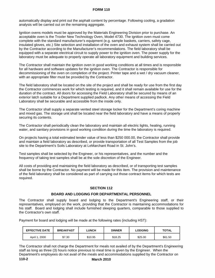
The Contractor shall supply board and lodging to the Department's Engineering staff, or their representatives, employed on the work, providing that the Contractor is maintaining accommodations for his staff. Board and lodging shall include furnished sleeping quarters, comparable to those supplied to the Contractor's own staff. Payment for board and lodging will be made at the following rates (including HST):
EFFECTIVE DATE BREAKFAST LUNCH DINNER LODGING TOTAL
April 1, 2000 $7.30 $10.95 $18.25 $25.00 $61.50
The Contractor shall not charge the Department for meals not availed of by the Department's Engineering staff as long as three (3) hours notice previous to meal time is given by the Engineer. When the Department's employees do not avail of the meals and accommodations supplied by the Contractor on

FORM 110
March 2010
110-3
weekends and holidays, payment will be made for lodging only. Should the Contractor provide accommodations for his staff, and insufficient space is made available for Department personnel, alternate arrangements will be made for Department personnel and costs associated for the alternate arrangements, in excess of the $25.00 for lodging specified above, are to be borne by the Contractor. SECTION 113 SANITARY PROVISIONS The Contractor shall provide and maintain sanitary provisions for the use of his employees. The sanitary provisions shall be in accordance with the various Provincial Government and Municipal Government Regulations.

MARCH 2010
190-1
SECTION 190 OCCUPATIONAL HEALTH AND SAFETY
190.1 GENERAL .1 All work is to be performed in accordance with the requirements of the Newfoundland
Occupational Health and Safety Act and regulations as amended. .2 Subsequent to awarding of the tender and at least 10 (ten) working days prior to
commencement of work, the contractor must submit to the Engineer copies of: .1 A detailed Health and Safety Risk Assessment and Management Plan for the owner. When Blasting is Required .2 Valid Blaster’s Journey Person Certificate and Certificates of Qualification identifying the
Level of Qualification for the project requirements. An acceptable letter of extension of blasters certificate from the Industrial Training Division of the Provincial Department of Education is required when certificate expires(5 years max.). Certificate numbers and names are required for all blasters proposed for the project.
.3 Blaster’s Safety Certificate from the Newfoundland Workplace Health and Safety Compensation Commission within the last 5 years for all blasters proposed for the project.
.4 Temporary Magazine License, when required .5 Explosives Vehicle Certificate, when required, issued by Transport Canada for transport
of explosives regulated under the Transportation of Dangerous Goods Act. .6 Blaster resume which clearly states and demonstrates: .1 Minimum five (5) years of experience in handling, storage and detonation of
explosives. .2 Training at a blaster’s school which is acceptable to the provincial government. When Diving is Required
.8 Diver(s) and dive supervisor (s). .1 Copy of valid Class 1 Diving Certificate or equivalent. .2 Resume which clearly demonstrates years of experience for the specific type
(SCUBA, Surface Supplied Air, etc.) of diving to be performed at the site and projects completed to achieve minimum number of logged bottom time, hours
.3 First aid and CPT Training Certification. .9 Dive tender(s) resume which clearly states relevant training (including first aid and
(CPR) and experience for the specific task (i.e. dive tender log book) .10 Current (less than one year) medical examination certificate (s) from a licensed medical
doctor in the Province of Newfoundland and Labrador who is knowledgeable and competent in diving and hyperbaric medicine for all dives.
.11 Certificates of Analysis for quality/purity of breathing air to be used by diver(s). .12 Documentation showing that diving life support equipment is in good working order and
properly maintained. .13 Copies of documentation shall be forwarded to: .1 Hyperbaric facility as well as standby physician for contingent emergency
response. .2 Copies of confined space entry training certificates where entry to confined
spaces may be required
.3 Acceptance of the Project Health and Safety Risk Assessment and Management Plan and other submitted documents by the Engineer shall only be viewed as acknowledgment that the contractor has submitted the required documentation under this specification section.. The Engineer makes no representation and provides no warranty for the accuracy, completeness and legislative compliance of the Project Health and Safety Risk Management Plan and other submitted documents by this acceptance. Responsibility for errors and omissions in the
GOVERNMENT OF NEWFOUNDLAND AND LABRADOR Department of Transportation and Works Highway Design Division

MARCH 2010
190-2
Project Health and Safety risk Assessment and Management Plan and other submitted documents is not relieved by acceptance by Engineer.
190.2 PROJECT HEALTH AND SAFETY RISK ASSESSMENT AND MANAGEMENT PLANS The contractor shall: .1 Conduct operations in accordance with latest edition of the Newfoundland Occupational Health
and Safety (OH&S) Act and Regulations. .2 Prepare a detailed Project Health and Safety Risk Assessment and Management Plan for the
Owner. The assessment shall identify, evaluate and control job specific hazards and the necessary control measures to be implemented for managing hazards.
.3 Provide a copy of the Project Health and Safety Risk Assessment and Management Plan to the Owner/Engineer. The written Health and Safety Risk Assessment and Management Plan shall incorporate the following:
.1 A site specific health and safety plan, refer Section 190.3 Site Specific Health and Safety Risk Assessment and Management Plan for requirements.
.2 An organizational structure which shall establish the specific chain of command and specify the overall responsibilities of contractors employees at the work site.
.3 A comprehensive work plan which shall: .1 define work tasks and objectives of site activities/operations and the
logistics and resources required to reach these tasks and objectives .2 establish personnel requirements for implementing the plan, and establish
site specific training and notification requirements and schedules. .4 A personal protected equipment (PPE) Program which shall detail PPE: .1 Selection criteria based on site hazards. .2 Use, maintenance, inspection and storage requirements and procedures. .3 Decontamination and disposal procedures. .4 Inspection procedures prior to during and after use, and other appropriate
medical considerations. .5 Limitations during temperature extremes, heat stress and other appropriate
medical consideration. .5 An emergency response procedure .6 A hazard communication program for informing workers, visitors and individuals
outside of the work area as required .7 A diving program which shall contain standard operating procedures to be
followed in the diving operation .8 A health and safety training program .9 General safety rules .4 Periodically review and modify as required each component of the Project Health and Safety
Risk Assessment and Management Plan when a new hazard is identified during completion of work and when an error or omission is identified in any part of the Project Health and Safety Risk Assessment and Management Plan
.5 Implement all requirements of the Project Health and Safety Risk Assessment and Management Plan.
.1 Ensure that every person entering the project site is informed of requirements under the Project Health and Safety Risk Assessment and Management Plan
.2 Take all necessary measures to immediately implement any engineering controls, administrative contacts, personal protective equipment required or termination of work procedures to ensure compliance with the Project Health and Safety Risk Assessment and Management Plan.
190.3 SITE SPECIFIC HEALTH AND SAFETY PLAN The contractor shall: .1 Prepare a detailed site Specific Project Health and Safety Plan which shall: .1 Contain certain hazard assessment results .2 Identify engineering and administrative demonstrative controls (work practices and
procedures) to be implemented for managing identified and potential hazards, and comply with applicable federal and provincial legislation and more stringent requirements that have been specified in these specifications.

MARCH 2010
190-3
.2 Review for completeness the hazard assessment results immediately prior to commencing work, when a new hazard is identified during completion of work and when an error or omission is identified.
.1 Be solely responsible for investigating, evaluation and managing any report of actual or potential hazards
.2 Retain copies of all completed hazard assessments at the project site and provide a copy to the Engineer/Architect
190.4 SUPERVISION AND EMERGENCY RESCUE PROCEDURE The contractor shall: .1 Carry out work under the direct supervision of competent persons responsible for safety by
ensuring the work complies with the appropriate section of OH&S Act and Regulations, latest edition
.2 Assign a sufficient number of supervisory personnel to the work site .3 Provide a suitable means of communications for workers required to work alone .4 Develop an emergency rescue plan for the job site and ensure that supervisors and workers
are trained in the emergency rescue plan .5 The emergency response plan shall address, as a minimum: .1 Pre-emergency planning .2 Personnel roles, lines of authority and communication. .3 Emergency recognition and prevention. .4 Safe distances and places of refuge .5 Site security and control .6 Evacuation routes and procedures .7 Decontamination procedures which are not covered by the site specific safety and
health plan .8 Emergency medical treatment and first aid. .9 Emergency alarm, notification and response procedures including procedures for
reporting incidents to local, provincial and federal government departments. .10 PPE and emergency equipment. .11 Procedures for handling emergency incidents. .12 Site specific emergency response training requirements and schedules. .13 For diving operation, include procedures for: .1 Managing deteriorating environmental conditions .2 Managing unexpected weather or sea state condition .3 Evacuation of diver(s) under pressures greater that atmospheric pressure .4 In water emergency transfers .5 Managing failing of equipment below the surface that impairs the ability of a diver
to complete a dive .6 Managing failure of any major component of diving plant or equipment .7 Emergency signaling between divers involved in the diving program and between
the diver(s) and the attendants using umbilical, tethers or other suitable methods .8 Mobilizing standby divers .9 Mobilizing crafts, standby boats and any other devices to be used for rescue .10 Contacting evacuation, rescue, treatment facilities and medical services that will
be used in the diving program .11 Operation of emergency power and lighting facilities .6 The emergency response procedures shall be rehearsed regularly as part of the overall
training program .7 Provide adequate first aid facilities for the job site and ensure that a minimum number of
workers are trained in first aid in accordance with the First Aid Regulations.
190.5 CONTRACTORS SAFETY OFFICER .1 The contractor’s Safety Officer will be solely responsible for the implementation and monitoring
of the Project Health and Safety Risk Assessment and Management Plan, and will have the authority to implement health and safety changes as directed by the Engineer. The Safety Officer shall have as a minimum:
.1 Completed training in hazardous occurrence management and response/protocols .2 Completed training in the use, maintenance of fall protection systems

MARCH 2010
190-4
.3 Completed training in the design and construction of scaffolding .4 Completed training in confined space entry protocols and techniques. .5 Completed training in First Aid. 190.6 HEALTH AND SAFETY COMMITTEE The contractor shall: .1 Establish an Occupational Health and Safety Committee where ten or more workers are
employed on the job site as per the OH&S Act and Regulations .2 Be responsible for health and safety of persons on site, safety of property on site and for
protection of persons adjacent to site and environment to extent that they may be affected by conduct of Work.
.3 Comply with and enforce compliance by employees with safety requirements of Contract Documents, applicable federal, provincial, territorial and local statutes, regulations, and ordinances, and with site specific Health and Safety Plan.
190.7 RESPONSIBILITY
.1 Should any unforeseen or peculiar safety related factor, hazard, or condition become evident during performance of Work, the contractor must:
.1 Follow procedures in place for Employee's Right to Refuse Work in accordance with Acts and Regulations
.2 Advise Engineer verbally and in writing 190.8 INSTRUCTION AND TRAINING .1 Workers shall not participate in or supervise any activity on the work site until they have been
trained to a level required by this job function and responsibility. Training shall, as a minimum, thoroughly cover the following:
.1 Federal and Provincial Health and Safety Legislation requirements including roles and responsibilities of workers and person(s) responsible for implementing, monitoring and enforcing health and safety requirements.
.2 Safety and health hazards associated with working on a contaminated site including recognition of symptoms and signs which might indicate over exposure to hazards.
.3 Limitations, use, maintenance and disinfection – decontamination of personal protective equipment associated with completing work.
.4 Limitations, use, maintenance and care of engineering controls and equipment. .5 Limitations and use of emergency notifications and response equipment including
emergency response protocol. .6 Work practices and procedures to minimize the risk of an accident and hazardous
occurrence from exposure to a hazard. .2 Contractors must provide and maintain training of workers, as required, by Federal and
Provincial legislation. .3 Copies of all training certificates shall be provided to the Engineer for review, before a worker
is to enter the work site. .4 Authorized visitors shall not access the work site until they have been: .1 Notified of the names of persons responsible for implementing, monitoring and enforcing
the health and Safety Risk Assessment and Management Plan. .2 Briefed on safety and health hazards present on the site. .3 Instructed in the proper use and limitations of personal protective equipment. .4 Briefed as the emergency response protocol including notification and evacuation
process. .5 Informed of practices and procedures to minimize risks from hazards and applicable to
activities performed by visitors. 190.9 CONSTRUCTION SAFETY MEASURES The contractor shall: .1 Observe construction safety measures of Provincial Government, OH&S Act and Regulations,
Workplace Health and Safety and Compensation Commission and Municipal Authority provided that in any case of conflict or discrepancy more stringent requirements shall apply
.2 Administer the project in a manner that will ensure, at all times, full compliance with Federal and Provincial Acts, regulations and applicable safety codes and the site Health and Safety Risk Assessment and Management Plan.

MARCH 2010
190-5
.3 Provide Engineer/Architect with copies of all orders, directions and any other documentation, issued by the Provincial Department of Government Services and Human Resources Development Canada (HRDC).
.4 Forward copies of all orders, directions or any other documentation immediately after receipt. 190.10 POSTING OF DOCUMENTS .1 Ensure applicable items, articles, notices and orders are posted in conspicuous location on
site in accordance with all Acts and Regulations . 190.11 HEALTH AND SAFETY MONITORING .1 Periodic inspections of the contractor’s work may be carried out by the Engineer and/ or the
Department of Transportation and Works Occupational Health and Safety Consultants to maintain compliance with the Health and Safety Program. Inspections will include visual inspections as well as testing and sampling as required.
.2 The contractor shall be responsible for any and all costs associated with delays as a result of contractor’s failure to comply with the requirements outlined in this section.
190.12 NOTIFICATION
.1 For projects exceeding thirty (30) days or more, the contractor shall, prior to the commencement of work, notify in writing the Work Place Health and Safety Division, Department of Government Services with the following information:
.1 Name and location of construction site .2 Company name and mailing address of contractor doing the work .3 The number of workers to be employed .4 A copy of the Health and Safety Risk Assessment and Management Plan if requested 190.13 CORRECTION OF NONCOMPLIANCE .1 Immediately address health and safety non-compliance issues identified by authority having
jurisdiction or by Engineer .2 Provide Engineer/Architect with written report of action taken to correct non-compliance of
health and safety issues identified .3 Engineer/Architect may stop work if noncompliance of health and safety regulations is not
corrected 190.14 WHMIS .1 Ensure that all controlled products are in accordance with the Workplace Hazardous Materials
Information System (WHMIS) Regulations and Chemical Substances of the OH&S Act and Regulations regarding use, handling, labeling, storage, and disposal of hazardous materials
.2 Deliver copies of relevant Material Safety Data Sheets (MSDS) to job site and the Engineer. The MSDS must be acceptable to Labour Canada and Health and Welfare Canada for all controlled products that will be used in the performance of this work.
.3 Train workers required to use or work in close proximity to controlled products as per OH&S Act and Regulations.
.4 Label controlled products at jobsite as per OH&S and Regulations. .5 Provide appropriate emergency facilities as specified in the MSDS where workers might be
exposed to contact with chemicals, e.g. eyewash facilities, emergency shower. .1 Workers to be trained in use of such emergency equipment. .6 Contractor shall provide appropriate personal protective equipment as specified in the MSDS
where workers are required to use controlled products. .1 Properly fit workers for personal protective equipment .2 Train workers in care, use and maintenance of personal protective equipment. .7 No controlled products are to be brought onsite without prior approved MSDS. .8 The MSDS are to remain on site at all times. 190.15 OVERLOADING .1 Ensure no part of work or associated equipment is subjected to loading that will endanger its
safety or will cause permanent deformation. 190.16 FALSEWORK .1 Design and construct falsework in accordance with CSA S269.1.
MARCH 2010
190-6
190.17 SCAFFOLDING .1 Design, erect and maintain scaffolding in accordance with CSA S269.2M87 and Sections 9197
of the OH&S Act and Regulations. .2 Ensure that fall restraint or fall arrest devices are used by all workers working at elevations
greater than 3.05 metres above grade or floor level in accordance with CSA Z259. 190.18 PERSONAL PROTECTIVE EQUIPMENT .1 In addition to those requirements set forth in the Occupational Health and Safety Act and
Regulations, all persons, including those employed by the contractor or sub-contractors, working on projects for The Department of Transportation and Works shall wear the following mandatory Personal Protective Equipment at ALL times while working on the project.
.1 CSA approved safety boots .2 CSA approved hard hat meeting the 1992 standard .3 vest with retro-reflective stripes .4 other personal protective equipment, as may be required from time to time by the
engineer, depending on duties being performed, shall also be worn 190.19 TRAFFIC CONTROL .1 Provide traffic control measures when working on, or adjacent to, roadways. .2 Traffic control measures to conform with “Traffic Control Manual for Roadway Work
Operations”, Department of Transportation and Works. 190.20 EXCAVATION SAFETY .1 Protect excavations more than 1.25 metres deep against cave ins or wall collapse by side wall
sloping to the appropriate angle of repose, an engineered shoring/sheathing system or an approved trench box
.2 Provide a ladder which can extend from the bottom of the excavation to at least 0.91 metres above the top of the excavation.
.3 Ensure that all excavations less than 1.25 metres deep are effectively protected when hazardous ground movement may be expected
.4 Design trench boxes, certified by a registered Professional Engineer, and fabricated by a reputable manufacturer. Provide the manufacturer’s Depth Certificate Statement permanently affixed. Use trench boxes in strict accordance with manufacturer’s instructions and depth certification data
.5 For excavations deeper than six (6) metres, provide a certificate from a registered Professional Engineer stating that the protection methods proposed have been properly designed in accordance with accepted engineering practice. The engineer’s certificate shall verify that the trench boxes, if used, are properly designed and constructed to suit the depth and soil conditions
.6 Ensure that the superintendent and every crew chief, foreperson and lead hand engaged in trenching operations or working in trenches have in his/her possession a copy of the Department of Government Service’s “Trench Excavation Safety Guide”
190.21 BLASTING OPERATIONS .1 Ensure blasting operations are carried out under the direct visual supervision of a qualified
Blaster registered with the Provincial Department of Government Services. Comply with the requirements of:
.1 Explosives Act. .2 Explosives Regulations. .3 Newfoundland Regulation 1165/96, Occupational Health and Safety Regulations. .2 Store explosives in accordance with the “Explosives Act (Canada)” and transport, handle and
use in the manner prescribed by the manufacturer of the substance and subject to specific regulations.
.3 Ensure that workers required to transport explosives have a valid Transportation of Dangerous Goods Training Certification in accordance with the “Act to Promote Public Safety in the Transportation of Dangerous Goods, and the “Explosives Act (Canada)”.
.4 Advise the public by suitable public notices, advertisements, house to house contacts etc. for blasting operations in close proximity to areas occupied by the public. Advise of the warning device to be sounded and the procedure to be used before detonation of individual blasts.
MARCH 2010
190-7
.5 Prior to detonation of a blast, give sufficient warning in every direction and ensure that all persons have reached a place of safety before the blast is fired.
.6 File an Emergency Response Assistance Plan with the Explosives Branch, Natural Resources Canada.
.7 Blaster shall: .1 Be solely responsible for implementation of the Explosives Management Program .2 Have a valid blaster’s safety certificate from the Department of Education Division of
Institutions and Industrial Education, and have a valid temporary Magazine License, when required issued by Natural Resources Canada, for storage and explosives
.3 Possess a thorough working knowledge of the Federal Explosives Act and Provincial Regulations
.4 Possess a specialized training in handling storage and detonation of explosives 190.22 HEAVY EQUIPMENT .1 Ensure mobile equipment used on job site is of the type specified in OH&S Act and
Regulations fitted with a Roll Over Protective Structure (ROPS). .2 Provide certificate of training in Power Line Hazards for operators of heavy equipment. .3 Obtain written clearance from the power utility where equipment is used in close proximity to
(within 5.5 metres) overhead or underground power lines .4 Equip cranes with: .1 A mechanism which will effectively prevent the hook assembly from running into the top
boom pulley. .2 A legible load chart .3 A maintenance log book 190.23 TREE AND BRUSH CLEARING .1 Ensure workers using chain saws wear the following safety equipment: .1 CSA approved safety hat fitted .2 Hearing protection, e.g. ear muffs .3 CSA approved chain saw pants .4 CSA approved chain saw boots .5 Approved eye protection .2 Ensure that all workers using brush saws wear the following safety equipment: .1 CSA approved safety hat fitted with face screen or shield or approved safety glasses .2 Hearing protection, e.g. ear muffs .3 CSA approved safety footwear .3 Chain saws must be equipped with a chain break 190.24 DIVING OPERATIONS .1 Ensure diving operations conform to CSA Z275.292 Occupational Safety Code for Diving
Operations and CSA Z275.497 Competency Standard for Diving Operations. .2 Sampling: .1 Prior to commencing diving activities, sample water and analyze sample(s) for: .1 Fecal Coliforms (Escherichia coli) .2 Total Coliforms. .3 Any health hazard identified during the site specific hazard assessment. .4 Any parameter as directed by the Department of Government Services,
Government of Newfoundland and Labrador. .2 Water will be designated a contaminant if the chemical concentration of a contaminant
exceeds: .1 200 fecal Coliforms (Escherichia coli) per 1000 milliliter of water. .2 100 times the guidelines concentration established in the most recent Guidelines
of Canadian Drinking Water Quality. .3 Any other criteria established by the Newfoundland Department of Government
Services. .3 Sample analysis is to be completed by a laboratory that is accredited by the Canadian
Associates of Environmental and Analytical Laboratories (CAEAL) or other national equivalent. .4 Dive personnel must meet the minimum competency requirements of CSA 275.497.
MARCH 2010
190-8
.1 The Dive supervisor(s) shall as a minimum: .1 Possess a Valid Category 1 Diving Certificate, or equivalent, for a minimum of
three (3) years for the type of diving to be performed. .2 Have completed one hundred and fifty (150) hours of logged diving time for the
type of diving to be performed. .3 Have completed fifty (50 ) hours of dive supervision for the type of diving to be
performed. .2 Diver(s) shall as a minimum: .1 Possess a valid Category 1 Diving Certificate or equivalent, for the type of diving
to be performed. .2 Have completed fifty (50) hours of logged dive time for the type of diving to be
performed. .5 A diving operation shall be interrupted or discontinued or not commenced when: .1 Continuation of the diving operation would or is likely to compromise the safety of any
person involved in the diving operation. .2 The water currents at the underwater work site are likely to compromise the safety of
any person involved in the diving operation. .3 Combustible material is stored too close for safety to any diving plant and equipment
used in the diving operation. .6 A diving operation shall: .1 Not be conducted in the vicinity for any other activity that might pose a danger to any
person involved in the diving operation. .2 Not use any craft that has insufficient power or stability for the safe continuity of the
diving operation. .3 Provide measures for making work area boundary and stopping unauthorized entry into
the work area. .4 Provide adequate illumination of the dive site and the underwater work site of the diving
operation. .7 Provide, at the work site while completing diving operations, a diving operations log book that
is permanently bound and has numbered pages. .1 Produce on request, any log books, records or other documentation associated with the
diving operation, for inspection by Engineer/Architect. .2 As a minimum, for each diving operation enter into the diving operation logbook: .1 date and time the diving operation commenced and terminated including any time
the diving operation was interrupted .2 name of supervisor; names of all other persons involved .3 the procedures followed .4 the decompression table and the schedule in that the decompression table was
used .5 the maximum depth, bottom time, dive time and total dive time for each dive .6 the type of diving plant and equipment and the type of breathing mixture used .7 the type of discomfort, injury or illness including decompression sickness,
suffered by any person involved .8 any environmental conditions that affected or might have affected the diving
operation .9 any other factors relevant to the safety to health of any person involved .8 Diving in free swim mode is not permitted at the work site. .9 Provide separate first aid supplies for dive operation. All dive team personnel shall be trained
in first aid and cardiopulmonary resuscitation (CPR) .10 Provide medical oxygen for emergency response at work site. The dive supervisor shall be
trained in administering medical oxygen. 190.25 The owner shall not be responsible for injury or damage occasioned by a failure of the
Contractor to adhere to these provisions.

FORM 330
MARCH 2010
330-1
SECTION 330
HOT MIX ASPHALT CONCRETE
INDEX
330.01 SCOPE
330.02 MATERIALS
330.02.01 Mixture Materials
330.02.01.01 Asphalt Cement
330.02.01.01.01 Performance Graded Asphalt Binder (PGAB) Sampling
330.02.01.01.02 Asphalt Binder Temperature Viscosity Chart
330.02.01.02 Crushed Aggregate
330.02.01.02.01 Coarse Aggregate
330.02.01.02.02 Fine Aggregate
330.02.01.02.03 Crushing Tolerances
330.02.01.03 Blending Sand (Naturally Occurring Screened Sand)
330.02.01.04 Mineral Filler
330.02.01.05 Anti-Stripping Additive
330.02.01.06 Recycled Asphalt Pavement (RAP)
330.02.02 Composition of Mixture
330.02.02.01 General Requirements for Pavement Mixture
330.02.02.02 Physical Requirements for Mixture
330.03 USE OF PITS, QUARRIES AND STOCKPILES
330.04 ENVIRONMENTAL PROVISIONS
330.04.01 Environmental Requirements for Asphalt Mixing Plants
330.04.02 Environmental Approval
330.05 METHOD SPECIFICATION FOR ASPHALT CONCRETE MIX - HOT PLACED
330.05.01 General
330.05.02 Testing and Inspection
330.05.02.01 Designation of Mixture
330.05.02.02 Unauthorized Tampering with Plant Settings and Materials
330.05.03 Equipment
330.05.03.01 Mixing Plants
330.05.03.01.01 General Requirements and Equipment for Storage of Asphalt Cement
330.05.03.01.02 Cold Bins
330.05.03.01.03 Dryer
GOVERNMENT OF NEWFOUNDLAND AND LABRADOR Department of Transportation and Works Highway Design Division

FORM 330
MARCH 2010
330-2
330.05.03.01.04 Screens
330.05.03.01.05 Hot Aggregate Storage Bins
330.05.03.01.06 Asphalt Cement Control Unit
330.05.03.01.07 Thermometric Equipment
330.05.03.01.08 Dust Collectors
330.05.03.01.09 Safety Requirements
330.05.03.01.10 Capacity
330.05.03.02 Special Requirements for Batching Plants
330.05.03.02.01 Weight Box or Hopper
330.05.03.02.02 Plant Scales
330.05.03.02.03 Mixer Unit
330.05.03.03 Special Requirements for Continuous Mixing Plants
330.05.03.03.01 Gradation Control Unit
330.05.03.03.02 Weight Calibration of Material Feed
330.05.03.03.03 Synchronization of Aggregate and Asphalt Feed
330.05.03.03.04 Mixer Unit
330.05.03.03.05 Discharge Hopper
330.05.03.03.06 Material Level Indicators
330.05.03.04 Special Requirements for Drum Mixer Plants
330.05.03.04.01 Aggregate Feed
330.05.03.04.02 Asphalt Cement Feed
330.05.03.04.03 Asphalt Cement Mixing
330.05.04 Truck Weigh Scales
330.05.05 Haulage Equipment
330.05.06 Spreading Equipment
330.05.07 Rollers
330.05.08 Material Transfer Device/Vehicle
330.05.09 Construction
330.05.09.01 Preparation of Gravel Road Surface
330.05.09.02 Preparation of Old Paved Surface
330.05.09.03 Placing of Asphaltic Courses
330.05.09.04 End of Paving Season for Asphaltic Surface Course
330.05.09.05 Joints
330.05.09.05.01 Keyed Joints
330.05.09.06 General Requirements for Compaction
330.05.09.06.01 Compacting Asphaltic Base, Levelling and Surface Courses
330.05.09.06.02 Compacting with Static Wheel Rollers
FORM 330
MARCH 2010
330-3
330.05.09.06.03 Asphalt Density Measurement and Unit Price Adjustment
330.05.09.07 Requirements for Asphaltic Leveling Course
330.05.09.08 Requirements for Completed Asphaltic Base and Surface Courses
330.05.09.09 Segregation and Other Surface Defects
330.05.10 Pavement Smoothness
330.05.10.01 Pavement Smoothness Measurement
330.05.10.02 Profile Index Limits
330.05.10.03 Surface Deviations (Individual Bumps and Dips)
330.05.10.04 Testing
330.05.10.05 Remedial Action
330.05.11 Asphaltic Patching
330.05.12 Measurement for Payment
330.05.12.01 Measurement for Payment for Asphaltic Surface Course, Asphaltic Base
Course, Asphaltic Leveling Course Type I & Type
330.05.12.02 Measurement for Payment for Asphaltic Patching
330.05.12.03 Measurement for Payment for Asphalt Cement
330.05.12.04 Measurement for Payment for Blending Sand
330.05.12.05 Measurement for Payment for the Cutting and Removal of Asphaltic Pavement
330.05.13 Basis of Payment
330.05.13.01 Basis of Payment for Asphaltic Surface Course, Asphaltic Base Course
Asphaltic Leveling Courses Type I & Type II
330.05.13.02 Basis of Payment for Asphaltic Patching
330.05.13.03 Basis of Payment for Asphalt Cement
330.05.13.04 Basis of Payment for Blending Sand
330.05.13.05 Basis of Payment for the Cutting and Removal of Asphaltic Pavement
330.05.13.06 Basis of Payment for Asphaltic Mix for Department's Maintenance Division
330.05.13.07 Basis of Payment for Rejected Mix
330.06 END PRODUCT SPECIFICATION FOR ASPHALT CONCRETE MIX - HOT PLACED
330.06.01 General
330.06.02 Definitions
330.06.02.01 End Product Specification (EPS)
330.06.02.02 Design Mix Formula (DMF)
330.06.02.03 Job Mix Formula (JMF)
330.06.02.04 Actual Asphalt Binder Content
330.06.02.05 Lot
330.06.02.06 Stratified Random Sample
330.06.02.07 Sample Mean

FORM 330
MARCH 2010
330-4
330.06.02.08 Mean of the Deviations
330.06.02.09 Thickness
330.06.02.10 Mix Property
330.06.02.11 Referee Sample
330.06.03 Materials
330.06.03.01 General
330.06.04 Mix Design Properties
330.06.04.01 Establishing a Design Mix Formula (DMF)
330.06.04.02 Requirements for Design Mix Formula
330.06.04.03 Submission of Design mix Formula
330.06.04.04 Evaluation of Design Mix Formula
330.06.04.05 Establishing a Job Mix Formula (JMF)
330.06.04.06 Approval Job Mix Formula
330.06.04.07 Field Adjustments to the Job Mix Formula
330.06.05 Construction Methods
330.06.05.01 General
330.06.05.02 Production
330.06.05.03 Transportation
330.06.05.04 Placement
330.06.05.05 Joint Construction
330.06.05.05.01 Transverse Construction Joints
330.06.05.05.02 Longitudinal Construction Joints
330.06.05.05.03 Paving in Echelon
330.06.05.05.04 Conventional Paving
330.06.05.05.05 Keyed Joints
330.06.06 Compaction
330.06.07 Surface Defects
330.06.08 Quality Control
330.06.08.01 Quality Control Inspection Testing Plan (ITP)
330.06.08.02 Sampling and Test Results
330.06.09 Quality Assurance
330.06.09.01 Sampling
330.06.09.02 Asphalt Binder Content, Gradation and Air Voids
330.06.09.03 Asphalt Density
330.06.09.04 Thickness (New Construction)
330.06.09.04.01 Material Application Rate (Rehabilitated Pavements)
330.06.09.05 Performance Graded Asphalt Binder (PGAB) Sampling

FORM 330
MARCH 2010
330-5
330.06.09.06 Pavement Smoothness
330.06.09.06.01 Profile Index limits
330.06.09.06.02 Surface Deviations (Individual Bumps and Dips)
330.06.10 Appeals
330.06.10.01 Appeal of Individual Test Results
330.06.10.02 Appeal of Test Results for the Entire Lot
330.06.10.02.01 Appeal of Lot Binder Content, Gradation and Air Void Content
330.06.10.02.02 Appeal of Lot or Trail Mix Density
330.06.10.02.03 Appeal of Lot or Trial Mix Thickness
330.06.10.02.04 Payment of Appeal Testing
330.06.11 Analysis of Rejected Lots
330.06.12 Repairs
330.06.12.01 Removal and Replacement
330.06.12.02 Overlaying
330.06.13 Method of Measurement
330.06.14 Basis of Payment
330.06.14.01 Basis of Payment for Asphaltic Surface, Asphaltic Base Course, Asphaltic
Levelling Course Type I and II, and Patching
330.06.14.02 Basis of Payment for Asphalt Cement
330.06.14.03 Basis of Payment for Rejected Mix
330.01 SCOPE This specification covers the Department's requirements for the production, placing and compaction of hot mix, hot laid base course, surface course and leveling course asphalt concrete for pavement construction. Sections 330.02 to 330.04 provides aggregate and asphalt pavement specifications and general requirements that are common to both method specification and end product specification projects. Section 330.05 provides specifications specific to method specifications projects, whilst Section 330.06 details the specifications for end product projects. Method specification projects are identified as projects where Department personnel conduct all materials testing and engineering services and the contractor’s payment is based upon tonnage of production for a specific project with some minimal performance criteria applied. End product specification projects are defined as projects where the contractor is solely responsible for quality control functions and the Department is responsible for the provision of all quality assurance testing. Payment to the contractor is also based on tonnage of production with a more extensive bonus/penalty system which in turn is based upon the end product quality assurance test results carried out by the Department. The base, surface and leveling course asphaltic concrete pavement shall consist of asphaltic cement, coarse and fine mineral aggregate, blending sand, plus mineral filler if required, combined as hereinafter specified, placed and compacted on a prepared base in conformity with the lines, grades, dimensions and cross sections, as staked by the Engineer. The paving of bridge decks and approach slabs shall be in accordance with Section 922 "Asphaltic Paving of Bridge Decks".
FORM 330
MARCH 2010
330-6
330.02 MATERIALS
330.02.01 Mixture Materials
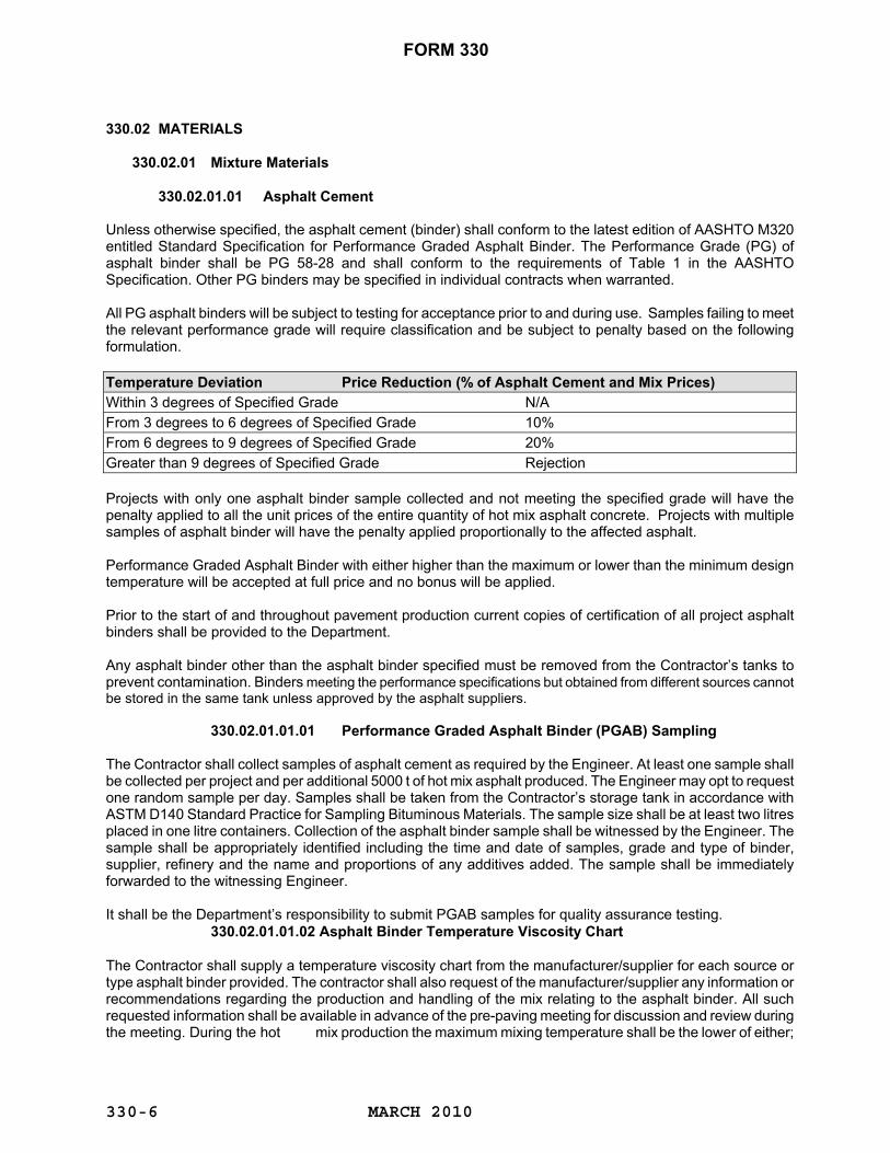
330.02.01.01 Asphalt Cement Unless otherwise specified, the asphalt cement (binder) shall conform to the latest edition of AASHTO M320 entitled Standard Specification for Performance Graded Asphalt Binder. The Performance Grade (PG) of asphalt binder shall be PG 58-28 and shall conform to the requirements of Table 1 in the AASHTO Specification. Other PG binders may be specified in individual contracts when warranted. All PG asphalt binders will be subject to testing for acceptance prior to and during use. Samples failing to meet the relevant performance grade will require classification and be subject to penalty based on the following formulation. Temperature Deviation Price Reduction (% of Asphalt Cement and Mix Prices) Within 3 degrees of Specified Grade N/A From 3 degrees to 6 degrees of Specified Grade 10% From 6 degrees to 9 degrees of Specified Grade 20% Greater than 9 degrees of Specified Grade Rejection Projects with only one asphalt binder sample collected and not meeting the specified grade will have the penalty applied to all the unit prices of the entire quantity of hot mix asphalt concrete. Projects with multiple samples of asphalt binder will have the penalty applied proportionally to the affected asphalt. Performance Graded Asphalt Binder with either higher than the maximum or lower than the minimum design temperature will be accepted at full price and no bonus will be applied. Prior to the start of and throughout pavement production current copies of certification of all project asphalt binders shall be provided to the Department. Any asphalt binder other than the asphalt binder specified must be removed from the Contractor’s tanks to prevent contamination. Binders meeting the performance specifications but obtained from different sources cannot be stored in the same tank unless approved by the asphalt suppliers. 330.02.01.01.01 Performance Graded Asphalt Binder (PGAB) Sampling The Contractor shall collect samples of asphalt cement as required by the Engineer. At least one sample shall be collected per project and per additional 5000 t of hot mix asphalt produced. The Engineer may opt to request one random sample per day. Samples shall be taken from the Contractor’s storage tank in accordance with ASTM D140 Standard Practice for Sampling Bituminous Materials. The sample size shall be at least two litres placed in one litre containers. Collection of the asphalt binder sample shall be witnessed by the Engineer. The sample shall be appropriately identified including the time and date of samples, grade and type of binder, supplier, refinery and the name and proportions of any additives added. The sample shall be immediately forwarded to the witnessing Engineer. It shall be the Department’s responsibility to submit PGAB samples for quality assurance testing. 330.02.01.01.02 Asphalt Binder Temperature Viscosity Chart The Contractor shall supply a temperature viscosity chart from the manufacturer/supplier for each source or type asphalt binder provided. The contractor shall also request of the manufacturer/supplier any information or recommendations regarding the production and handling of the mix relating to the asphalt binder. All such requested information shall be available in advance of the pre-paving meeting for discussion and review during the meeting. During the hot mix production the maximum mixing temperature shall be the lower of either;

FORM 330
MARCH 2010
330-7
the high end temperature for recommended mixing from the temperature viscosity chart provided by manufacturer/supplier or 165° C. 330.02.01.02 Crushed Aggregate Additional to all other requirements, the designated aggregates shall be split on the 4.75 mm screen during crushing operations, and each material shall be stockpiled separately such that intermixing of each size and type does not occur. Where aggregates are processed from pits the naturally occurring fines shall be pre-screened prior to crushing, individually stockpiled and referenced as “naturally occurring fine aggregate“. No more than 5% naturally occurring fine aggregate passing the 4.75 mm screen shall be permitted with the retained naturally occurring screened coarse aggregate prior to crushing. Naturally occurring coarse aggregate must be stockpiled separately prior to crushing. Fine aggregate sizes generated during the crushing phase shall also be individually stockpiled and identified as “crushed fines”. In no cases shall the fine aggregate stockpiles be combined or mixed with other aggregate types.
330.02.01.02.01 Coarse Aggregate
Coarse Aggregate shall consist of hard, durable crushed stone or crushed gravel particles, reasonably uniform in quality and free from soft or disintegrated pieces. The portion of material retained on the 4.75 mm sieve shall be known as coarse aggregate. The coarse aggregate stockpile shall contain no more than 20% passing the 4.75 mm screen. Coarse Aggregates shall be washed if necessary to have clean surfaces free from coatings of foreign matter. Coarse Aggregates shall conform to the physical requirements shown in Table 1. Irrespective of compliance with the physical requirements of Tables 1, any coarse aggregate may be accepted or rejected on the basis of past field performance at the discretion of the department.
TABLE 1 Physical Requirements For Coarse Aggregates
HIGHWAY CLASSIFICATION
RAU & RAD-100 RAU & RAD-90,
RCU-80
RLU-60, RLU-70
RLU-80
TEST METHOD
TEST NO.
SURFACE
BASE
ALL COURSES LOS ANGELES ABRASION - % MAXIMUM (A)
ASTM C131
35
35
35
ABSORPTION - % MAXIMUM
ASTM C127
1.75
2
2
MAGNESIUM SULPHATE - SOUNDNESS - 5 CYCLES - % MAXIMUM (B)
ASTM C88
12
12
12
PETROGRAPHIC NUMBER - MAXIMUM
CSA A23.2-15A
135
135
135
FREEZE-THAW TEST - 5 CYCLES - % MAXIMUM
CSA A23.2-24A
8
10
10
CRUSHED PARTICLES -% MINIMUM (C)
ASTM D5821
90
90
70
FLAT & ELONGATED PARTICLES - % MAXIMUM (D)
ASTM D 4791
20
20
20
LOSS BY WASHING - % MAXIMUM PASSING (E)
ASTM C117
1.75
1.75
1.75
MICRO DEVAL - % MAXIMUM
ASTM D 6928
20
20
20
CLAY LUMPS -% MAXIMIM
CSA A23.2-3A
1
1
1
LOW DENSITY PARTICLES - % MAXIMUM
CSA A23.2-4A
1
1
1
FRIABLE OR SLATEY SILTSTONE - % MAXIMUM
CSA A23.2-15A
1
1
1

FORM 330
MARCH 2010
330-8
Notes: (A) The ratio of the loss after 100 revolutions to the loss after 500 revolutions shall not exceed 0.265. (B) Test to be conducted on basalt rich or highly absorptive (> 1.5%) aggregates. (C) Pieces having two or more freshly fractured faces only will be considered as crushed material.
Pieces with only small chips removed will not be considered as crushed. (D) Flat and elongated pieces are those whose greatest dimension exceeds four times their least
dimension. (E) When only quarried rock is used as a source of coarse aggregate, a maximum of 2 percent passing the
75 μm sieve shall be permitted.
330.02.01.02.02 Fine Aggregate
Fine aggregate shall consist of clean, tough, rough-surfaced grains, free from clay, loam and other foreign matter.The fine aggregate stockpile shall contain no more than 20% retained on the 4.75 mm screen. The maximum allowable percentage of non-crushed fine aggregate in the total combined aggregate shall be 20% inclusive of all natural occurring fines and blending sands. Irrespective of compliance with the physical requirements of Tables 2 any fine aggregate may be accepted or rejected on the basis of past field performance at the discretion of the department.
TABLE 2
Physical Requirements for Fine Aggregates Test Method
Test No.
All Courses
MICRO-DEVAL TEST FOR FINE AGGREGATE - % MAXIMUM
CSA A23.2-23A
20
PLASTICITY INDEX
ASTM D4318
0
SAND EQUIVALENT - % MINIMUM
ASTM D 2419
Min 50
FINE AGGREGATE ANGULARITY - % MINIMUM (A)
ASTM C 1252
45
Note: (A) FAA tests shall be conducted on a representative sample of the total fine aggregate inclusive of all
fine aggregate materials as indicated in the mix design including blending sand. The test will be conducted in accordance with Standard Graded Sample Method A
330.02.01.02.03 Crushing Tolerances After the Contractor starts crushing, an average grading will be determined and tolerances will be applied to subsequent production. The average grading will be determined by averaging at least six washed sieved results on a minimum of 1500 tonnes or 30% of the required amount. The tolerances for subsequent production are as follows:
Tolerance for Production of Asphalt Aggregate Aggregate Passing 25.0 mm to 9.5 mm sieves Aggregate Passing 4.75 mm sieve Aggregate Passing 2.00 mm sieve Aggregate Passing 425 µm sieve Aggregate Passing 150 μm sieve Aggregate Passing 75 µm sieve
± 6% ± 5% ± 4% ± 4% ± 3% ± 2%
FORM 330
MARCH 2010
330-9
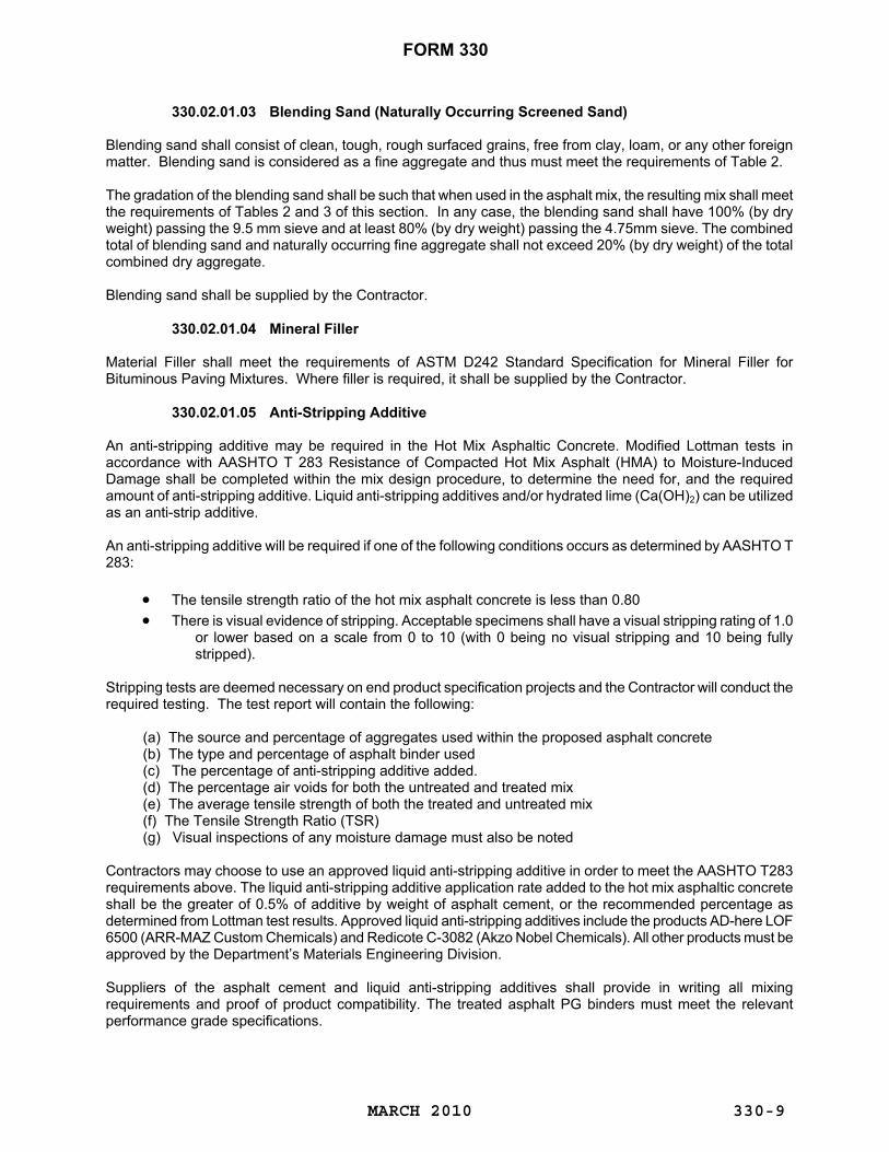
330.02.01.03 Blending Sand (Naturally Occurring Screened Sand) Blending sand shall consist of clean, tough, rough surfaced grains, free from clay, loam, or any other foreign matter. Blending sand is considered as a fine aggregate and thus must meet the requirements of Table 2. The gradation of the blending sand shall be such that when used in the asphalt mix, the resulting mix shall meet the requirements of Tables 2 and 3 of this section. In any case, the blending sand shall have 100% (by dry weight) passing the 9.5 mm sieve and at least 80% (by dry weight) passing the 4.75mm sieve. The combined total of blending sand and naturally occurring fine aggregate shall not exceed 20% (by dry weight) of the total combined dry aggregate. Blending sand shall be supplied by the Contractor.
330.02.01.04 Mineral Filler
Material Filler shall meet the requirements of ASTM D242 Standard Specification for Mineral Filler for Bituminous Paving Mixtures. Where filler is required, it shall be supplied by the Contractor.
330.02.01.05 Anti-Stripping Additive An anti-stripping additive may be required in the Hot Mix Asphaltic Concrete. Modified Lottman tests in accordance with AASHTO T 283 Resistance of Compacted Hot Mix Asphalt (HMA) to Moisture-Induced Damage shall be completed within the mix design procedure, to determine the need for, and the required amount of anti-stripping additive. Liquid anti-stripping additives and/or hydrated lime (Ca(OH)2) can be utilized as an anti-strip additive. An anti-stripping additive will be required if one of the following conditions occurs as determined by AASHTO T 283:
• The tensile strength ratio of the hot mix asphalt concrete is less than 0.80 • There is visual evidence of stripping. Acceptable specimens shall have a visual stripping rating of 1.0
or lower based on a scale from 0 to 10 (with 0 being no visual stripping and 10 being fully stripped).
Stripping tests are deemed necessary on end product specification projects and the Contractor will conduct the required testing. The test report will contain the following:
(a) The source and percentage of aggregates used within the proposed asphalt concrete (b) The type and percentage of asphalt binder used (c) The percentage of anti-stripping additive added. (d) The percentage air voids for both the untreated and treated mix (e) The average tensile strength of both the treated and untreated mix (f) The Tensile Strength Ratio (TSR) (g) Visual inspections of any moisture damage must also be noted
Contractors may choose to use an approved liquid anti-stripping additive in order to meet the AASHTO T283 requirements above. The liquid anti-stripping additive application rate added to the hot mix asphaltic concrete shall be the greater of 0.5% of additive by weight of asphalt cement, or the recommended percentage as determined from Lottman test results. Approved liquid anti-stripping additives include the products AD-here LOF 6500 (ARR-MAZ Custom Chemicals) and Redicote C-3082 (Akzo Nobel Chemicals). All other products must be approved by the Department’s Materials Engineering Division. Suppliers of the asphalt cement and liquid anti-stripping additives shall provide in writing all mixing requirements and proof of product compatibility. The treated asphalt PG binders must meet the relevant performance grade specifications.

FORM 330
MARCH 2010
330-10
Contractors must inform the Engineer and advise workers of the proper procedures, use of protective clothing and equipment when handling anti-stripping additives. Hot mix asphaltic concrete with liquid anti-strip additives is known to produce strong odours. Contractors must ensure the mix materials are used under proper environmental conditions to guarantee the safety and comfort of construction personnel and the public. In addition to AASHTO T 283 requirements, the asphalt hot mix containing liquid anti-stripping additive shall pass a boiling water test in accordance with ASTM D3625 Standard Practice for the Effect of Water on Bituminous-Coated Aggregate Using Boiling Water within the mix design procedure. The pass criterion for ASTM D 3625 is 95% or greater retained bitumen coating of aggregate. An additional rate of liquid anti-strip and/or an alternate anti-stripping additive will also be required if the aggregate is known to be prone to stripping from past performance and the minimum application rate was insufficient. Modified Lottman Tests (AASHTO T 283) and Boiling Water Tests (ASTM D3625) shall also be conducted on field produced samples of hot mix. All field produced samples shall also pass the requirements above. If liquid anti-stripping additive is required as described above and utilized by the contractor payment is set at twenty five dollars ($25) per tonne of asphalt cement based on the quantity of cement as determined under 330.05.12.03 or 330.06.13.02 Measurement for Payment for Asphalt Cement as applicable. This payment price is compensation in full for all labor, materials and equipment to supply the liquid anti-stripping additive, mix the additive with the asphalt cement and utilize in accordance with the requirements set forth above. Hydrated lime (Ca(OH)2) can also be utilized as an anti-strip additive. Where hydrated lime is used as an anti-strip additive the dosage requirement shall be the greater of one half (1/2) percent by mass of total dry aggregate, or the recommended percentage as determined from Lottman test results. Where hydrated lime is utilized the hydrated lime shall be added to all aggregates by either of the following methods:
(a) Hydrated lime slurry shall be homogeneously mixed with the aggregate in a pug-mill or tumble mixer prior to entering the asphalt plant (the hydrated lime slurry shall be produced at the approximate rate of 1 part lime to 3-4 parts water).
(b) Dry hydrated lime shall be homogeneously mixed with wetted aggregate in a pug-mill or tumble mixer prior to entering the asphalt plant. The wetted aggregate shall have a minimum moisture content of 2% by weight for coarse aggregate and 3% by weight for fine aggregate.
Hydrated lime shall be mixed with the aggregate at least 4 hours prior to entering the asphalt plant. Aggregate treated with hydrated lime shall be used within the same construction season. Treatment shall include both coarse and fine aggregate components of the asphalt aggregate. Where hydrated lime is required, the Contractor shall provide the Department with complete information on how the hydrated lime is to be used in the treatment of aggregates. Hot mix produced containing hydrated lime, shall conform to all requirements of the contract before acceptance. The requirement for hydrated lime anti-stripping additive will be determined following the mix design. The design amount of hydrated lime will be added as a percentage of the total dry aggregate weight. Measurement for hydrated lime anti-stripping additives shall be determined by the Department on the basis of the computed quantity calculated from the percentage of anti-stripping additive specified in the mix design and the total asphalt cement or dry aggregate used by the Contractor. If hydrated lime anti-stripping additive is required, payment is set at three hundred seventy five dollars ($375) per tonne. This payment price is compensation in full for all labor, materials and equipment to supply the hydrated lime anti-stripping additive, mix the hydrated lime with water (if necessary) and add the hydrated lime in accordance with the requirements set forth above. If an anti-stripping additive or additional/alternative anti-stripping additives are required, a further 10 working days will be required after the Contractor has advised the Department of its new anti-strip proposal and all

FORM 330
MARCH 2010
330-11
materials have been received by the Materials Engineering Division. The Contractor and his supplier shall provide sample materials, any technical information and Manufacturer’s recommended application rates.
330.02.01.06 Recycled Asphalt Pavement (RAP)
If the Contractor wishes, the Contractor will be permitted to use Recycled Asphalt Pavement (RAP) in levelling or base course asphalt. The amount of RAP in the pavement mixture will be limited to 20% and subject to the following conditions:
Preparation and submission of a Marshall Asphalt Design Mix Formula (including all supporting documentation) for the asphalt mixture containing RAP, for the Department’s approval, is the responsibility of the Contractor. The Contractor shall use professional engineering services and a qualified testing laboratory, to assess the aggregate materials, asphalt binders, blending sands, mineral fillers, anti-stripping agents and asphalt cement rejuvenation agents proposed for use and to carry out the design of the asphalt concrete mix. No compensation will be provided to the Contractor, for the production of the asphalt design mix formula for the asphalt mixture containing RAP.
The asphalt mixture containing RAP shall be designed in accordance with the Ontario Ministry of Transportation, Design Procedure for Recycled Hot Mix Asphalt, latest edition, except that all test methods referred to shall be replaced with the appropriate ASTM Standards. Copies of this document are available from the Departments Materials Engineering Division.
RAP percentages may require the use of asphalt cement rejuvenation agents to ensure the overall asphalt cement characteristics meet the specified Performance Grade. Testing to confirm the rheological characteristics of the combined Performance Graded Asphalt Cement and the RAP asphalt cement shall be supplied as part of the Marshall Mix Design. In all cases the Performance Grade of the asphalt cement shall meet the project specifications.
RAP shall be comprised of asphalt millings and be free of uncoated particles. The use of non-milled reclaimed asphalt pavement is subject to the approval of the Department.
The quality of the aggregate in the RAP and the quality of the final pavement mixture shall meet all requirements set forth in this specification.
Where RAP is included in base or levelling course mixes the following process will be followed: -RAP shall be fractionated into a minimum of three separate sizes. - The gradation of the individual fractionated RAP shall be: - 9.5mm and above - 4.75mm to 9.5mm - minus 4.75mm -The asphalt plant must be equipped with a metering system that allows the fractionated RAP to be added in a controlled manner acceptable to the Department.
The Contractor shall provide the Department with a minimum 30 day notice of his intention to use RAP. The Department reserves the right to accept or reject any particular source of RAP, irrespective of its quality.
330.02.02 Composition of Pavement Mixture
330.02.02.01 General Requirements for Pavement Mixture The mixture shall consist of suitably graded fine and coarse aggregate thoroughly mixed with asphalt cement as specified. Blending sand, filler and chemical additives shall be added when required. Unless otherwise specified, the aggregates shall be combined in such proportions as to produce a mixture conforming to the grading of Table 3.

FORM 330
MARCH 2010
330-12
TABLE 3 Asphalt Aggregate Mixtures
Percent Passing by Dry Weight
Sieve Size Surface Course
Levelling Course
Type I**
Base Course & Levelling Course
Type II*** 22.0 mm
100
100
100
19.0 mm
100
100
90-100 12.5 mm
93-100
75-100
75-90
9.5 mm
75-92
63-84
63-84 4.75 mm 55-75 35-70
35-70
2.00 mm
32-55
20-55 20-55 0.425 mm
12-25
10-25
10-25
0.150 mm 5-12 5-12 5-12
0.075 mm
3-7*
3-7*
3-7*
Asphalt Cement (% By Weight of Total Mixture) 4.5 – 7.0 4.5 – 7.0 4.5 – 7.0
* The dust/effective asphalt ratio of all mixtures shall be between 0.6 and 1.2. Dust is defined as material
passing the 0.075 mm sieve. ** Levelling Course Type I to be used where thickness of compacted lift is to be less than or equal to 30
mm. *** Levelling Course Type II to be used where thickness of compacted lift is to be greater than 30 mm. Once a mix design has been designated or approved by the Engineer, the Contractor shall be required to produce a pavement mixture conforming to the following mix control tolerances. The mix must still fall inside the gradation envelopes of Table 3.
Individual Sample Tolerance for Production of Combined HMA Aggregate Passing 19.0 mm sieve Aggregate Passing 12.5 mm sieve Aggregate Passing 9.5 mm sieve Aggregate Passing 4.75 mm sieve Aggregate Passing 2.00 mm sieve Aggregate Passing 425 µm sieve Aggregate Passing 150 µm sieve Aggregate Passing 75 µm sieve
± 5% ± 5% ± 5% ± 5% ± 4% ± 3% ± 2% ± 1%
330.02.02.02 Physical Requirements for Mixture The aggregates and the asphalt cement shall be mixed in such proportions as to satisfy the criteria contained in Table 4. These criteria are based on the Standard Marshall Test Procedures and using a compactive effort of 75 blows on each face of the specimen. All test procedures used shall be the latest versions of ASTM or AASHTO standards, except where indicated.
TABLE 4 Physical Requirements for Asphaltic Concrete Mixture (All Courses)
Minimum
Maximum MARSHALL STABILITY N. AT 60OC (I) FOR HIGHWAY CLASSIFICATIONS RLU-60, RLU-70, RLU-80
5 400
---

FORM 330
MARCH 2010
330-13
(II) FOR HIGHWAY CLASSIFICATIONS RAU & RAD-100, RAU & RAD-90, RCU-80 8 000 --- MARSHALL FLOW INDEX MM
2.5
4.25
% AIR VOIDS (A) (I) FOR HIGHWAY CLASSIFICATIONS RLU-60, RLU-70, RLU-80 (II) FOR HIGHWAY CLASSIFICATIONS RAU & RAD-100, RAU & RAD-90, RCU-80
2.5 3.0
4.0 5.0
% VOIDS IN COMPACTED MINERAL AGGREGATES (I) LEVELING & BASE COURSE (II) SURFACE COURSE
14.0 15.0
--- ---
MODIFIED LOTMAN AASHTO T283 - TENSILE STRENGTH RATIO
0.7
---
MOISTURE CONTENT OF HOT MIX ASPHALT BY OVEN METHOD, AASHTO T329 AS PERCENT OF HMA
---
0.3
Notes: (A)The test method, ASTM D2041 "Theoretical Maximum Specific Gravity and Density of
Bituminous Paving Mixture", shall be modified as follows: The residual pressure in the vacuum cell shall be 30 mm ±1 mm.
330.03 USE OF PITS, QUARRIES AND STOCKPILES The use of pits and quarries for the production of the aggregates, together with the requirements for the stockpiling of the aggregates shall be in compliance with the provisions of Section 310 "Use of Pits, Quarries and Stockpiles for Production of Materials Supplied by Contractor". 330.04 ENVIRONMENTAL PROVISIONS Pits and quarries shall be stripped, worked and at the completion of the work restored, all in compliance with the provisions of Section 310 "Use of Pits, Quarries and Stockpiles for Production of Materials Supplied by the Contractor". Off-specification asphalt shall be disposed of in accordance with Division 8.
330.04.01 Environmental Requirements for Asphalt Mixing Plants Any asphalt plant being operated within a radius of 1.5 km of a regularly used building, either residential or commercial, or an organized recreational area, must control their dust emissions such that compliance is obtained with the air standards enforced by the Department of Environment and Conservation. In order to comply, the efficient operations of either a bag house dust collector or a water scrubber on the dryer emissions would be necessary. These controls may be waived in an area where there are three or less regularly used buildings if the Contractor makes satisfactory arrangements with the owners and occupiers of all buildings. Under such circumstances, a written agreement between the Contractor and owner/occupier, signed by both parties, must be submitted to both the Department of Transportation and Works and the Department of Environment and Conservation. Contractors are referred to the "Environmental Code of Practice for Asphalt Plant Operations" prepared by the Department of Environment and Conservation (Latest Edition). Hydrocarbon storage shall be in accordance with Section 820. The Contractor shall follow the procedure for spill reporting. All sections of the asphalt plant which could contribute to air or water pollution must be maintained in efficient operating condition. Where a water scrubber is used, the scrubber effluent must be given retention time in suitably sized artificial settling ponds. Such ponds must be sufficiently impermeable to enable seepage water to meet the Environment Control (water and sewage) Regulations, 2003.

FORM 330
MARCH 2010
330-14
All storage tanks for fuel must be drained within one week after production has been completed. Fuel oil must not remain in tanks over the winter.
330.04.02 Environmental Approval Contractors wishing to set up an asphalt mixing plant at a site must first obtain environmental approval before proceeding. Contractors must apply in writing to the Department of Government Services and Lands for a Ministerial Approval as required under the Department of Environment Act, 2002. The following information must be supplied with the application:
For inspection purposes, the Contractor is to notify the Department of Environment and Conservation at least five days prior to site closure. Should the Contractor wish to leave his equipment at the site beyond the completion of his work for this Department, or beyond his proposed completion date as stated in his application, then the Contractor shall state in writing his commitment to undertake the cleanup and restoration requirements of this section and those of Section 310 "Use of Pits, Quarries and Stockpiles for Production of Materials Supplied by Contractor", and also state his updated proposed completion date. Copies of this letter shall be sent to both the Department of Transportation and Works and the Department of Environment and Conservation. 330.05 METHOD SPECIFICATION FOR ASPHALT CONCRETE MIX - HOT PLACED
330.05.01 GENERAL
This item consists of supplying crushed aggregates, sand and mineral filler, anti-stripping additive, asphalt binder, with the production, loading, hauling, placing and compaction of hot mix asphalt concrete. The limits of placement, application rates and the asphalt concrete mixture type shall be as stated in the contract specifications. Production and Placement of hot mix asphalt will be subjected to various quality tests.
All aspects of the production and placement of the Hot Mix Asphalt will be supervised by the Department. All appropriate inspection and testing will be determined by the Department.
1. LOCATION OF THE PROPOSED SITE AND
DESCRIPTION OF ITS SURROUNDINGS WITHIN A RADIUS OF 1.5 KM.
2. SOIL TYPE AND PARTICULARS OF PROTECTIVE DYKING NEAR STORAGE TANKS.
3. SIEVE ANALYSIS OF COLD FEED AGGREGATE OR AT LEAST THE PERCENTAGE OF MINUS 75 F SIEVE.
4. DESCRIPTION OF THE PLANT AND ASSOCIATED EQUIPMENT TO REDUCE AIR CONTAMINANTS (PLANS IF AVAILABLE).
5. CAPACITY OF PLANT IN TONNES PER HOUR. 6. SOURCE OF HEAT (AND SULPHUR CONTENT
IF IT IS OIL). 7. RATE OF AIR FLOW THROUGH THE DRYER
AT OPERATING CONDITIONS AND DIAMETER OF THE DRYER.
8. RELEVANT OPERATION DETAILS OF AIR POLLUTION CONTROL EQUIPMENT (IE. PRESSURE DROP ACROSS CYCLONES OR SCRUBBERS)
9. AIR TO CLOTH RATIO IF BAGHOUSE FILTER IS USED.
10. HEIGHT OF EXHAUST STACKS. 11.TEMPERATURE AND VELOCITY OF EXHAUST
GASES FROM DRYER AND/OR STACK. 12. EXPECTED DATES OF OPERATION OF THE
PLANT: - PROPOSED STARTING DATE
- HOURS IN OPERATION PER DAY - PROPOSED COMPLETION DATE
- TOTAL DAYS IN OPERATION 13.IF USING A WATER SCRUBBER, THE RATE OF
USE OF WATER (L/S),THE NUMBER AND DIMENSIONS OF SETTLING PONDS AND THE METHOD OF LINING OF THE PONDS

FORM 330
MARCH 2010
330-15
The mixing period and temperature shall be such as to produce a uniform mixture in which all the particles are thoroughly coated, and the moisture content of the material as it leaves the mixer must be reduced to 0.3% or less. Facilities for sampling and observing the mix shall be provided. The temperature of the mix immediately after mixing shall not exceed 165oC. Quality control tests shall be performed, by the Department, on random samples taken either at the production site or lay-down site. Asphalt concrete is defined as a carefully controlled mixture of asphalt cement and mineral aggregate thoroughly mixed to be free from segregation and contamination and then placed and compacted to a uniform density and smooth finish. The following sections describe the requirements applicable to quality control and quality assurance, manufacturing, transportation, placing, compaction, finishing and measurement and payment of asphalt concrete. The requirements of specific materials for the asphalt concrete are described in Section 330.02.
330.05.02 TESTING AND INSPECTION The Contractor shall provide a field laboratory in accordance with the provisions of Section 111 "Field Laboratory". The field laboratory shall be provided at the site of the asphalt mixing plant. The requirements for pit and quarry sampling and processed material sampling and approval as set forth in Section 310 "Use of Pits, Quarries and Stockpiles for Production of Materials Supplied by Contractor", shall apply to this section. The Contractor shall send to the Department's Laboratory in St. John's, samples of the proposed paving aggregate for testing as to quality, mix design, and approval by the Engineer. No samples will be accepted for mix design until 100% of the total aggregate required (including filler and blending sand) has been crushed, tested and properly stockpiled. The Contractor shall be notified of the designated composition of the mixture not later than ten (10) working days after the day on which all necessary samples have been received at the Department's Laboratory and shall not commence mix production before such notification.
330.05.02.01 Designation of Mixture The Engineer shall specify or approve a job mixture within the required limits of grading and conforming to the Marshall Test requirements given in Table 4 of Section 330.02.02 for each mix selected. The Engineer may select one or more mix proportions to suit job conditions. The actual grading of the job mix, when plotted, shall so range from course through fine sizes that it will approximate the shape of the plotted average grading for corresponding mix given in Table 3 Section 330.02.02. For that portion of the aggregate passing the 4.75 mm sieve, gradients which range from the maximum of one sieve to the minimum of the next larger sieve, shall not be permitted. 330.05.02.02 Unauthorized Tampering with Plant Settings and Materials
Any person employed by the Contractor, who, in the opinion of the Engineer, alters or causes to be altered, any settings or screens of an asphalt plant after it has been calibrated, or who adds or causes to be added, any unapproved material to a stockpile or aggregate, or in any way hampers the production of the mix as designed, shall at the written request of the Engineer, be forthwith removed from the project and such persons shall not again be employed in the work.
330.05.03 EQUIPMENT
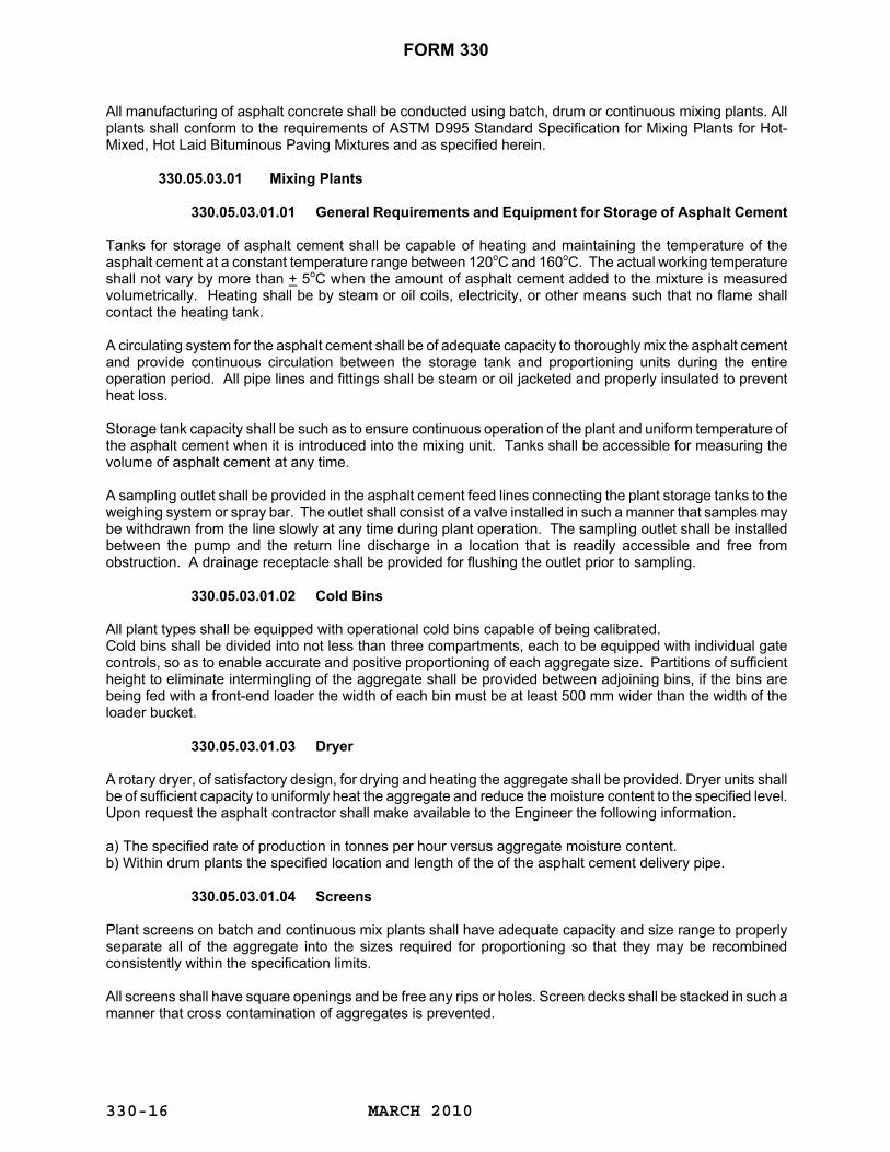
FORM 330
MARCH 2010
330-16
All manufacturing of asphalt concrete shall be conducted using batch, drum or continuous mixing plants. All plants shall conform to the requirements of ASTM D995 Standard Specification for Mixing Plants for Hot-Mixed, Hot Laid Bituminous Paving Mixtures and as specified herein.
330.05.03.01 Mixing Plants
330.05.03.01.01 General Requirements and Equipment for Storage of Asphalt Cement
Tanks for storage of asphalt cement shall be capable of heating and maintaining the temperature of the asphalt cement at a constant temperature range between 120oC and 160oC. The actual working temperature shall not vary by more than + 5oC when the amount of asphalt cement added to the mixture is measured volumetrically. Heating shall be by steam or oil coils, electricity, or other means such that no flame shall contact the heating tank.
A circulating system for the asphalt cement shall be of adequate capacity to thoroughly mix the asphalt cement and provide continuous circulation between the storage tank and proportioning units during the entire operation period. All pipe lines and fittings shall be steam or oil jacketed and properly insulated to prevent heat loss. Storage tank capacity shall be such as to ensure continuous operation of the plant and uniform temperature of the asphalt cement when it is introduced into the mixing unit. Tanks shall be accessible for measuring the volume of asphalt cement at any time. A sampling outlet shall be provided in the asphalt cement feed lines connecting the plant storage tanks to the weighing system or spray bar. The outlet shall consist of a valve installed in such a manner that samples may be withdrawn from the line slowly at any time during plant operation. The sampling outlet shall be installed between the pump and the return line discharge in a location that is readily accessible and free from obstruction. A drainage receptacle shall be provided for flushing the outlet prior to sampling.
330.05.03.01.02 Cold Bins
All plant types shall be equipped with operational cold bins capable of being calibrated. Cold bins shall be divided into not less than three compartments, each to be equipped with individual gate controls, so as to enable accurate and positive proportioning of each aggregate size. Partitions of sufficient height to eliminate intermingling of the aggregate shall be provided between adjoining bins, if the bins are being fed with a front-end loader the width of each bin must be at least 500 mm wider than the width of the loader bucket.
330.05.03.01.03 Dryer A rotary dryer, of satisfactory design, for drying and heating the aggregate shall be provided. Dryer units shall be of sufficient capacity to uniformly heat the aggregate and reduce the moisture content to the specified level. Upon request the asphalt contractor shall make available to the Engineer the following information. a) The specified rate of production in tonnes per hour versus aggregate moisture content. b) Within drum plants the specified location and length of the of the asphalt cement delivery pipe.
330.05.03.01.04 Screens Plant screens on batch and continuous mix plants shall have adequate capacity and size range to properly separate all of the aggregate into the sizes required for proportioning so that they may be recombined consistently within the specification limits. All screens shall have square openings and be free any rips or holes. Screen decks shall be stacked in such a manner that cross contamination of aggregates is prevented.

FORM 330
MARCH 2010
330-17
330.05.03.01.05 Hot Aggregate Storage Bins Batch and continuous mix plants shall have hot bin storage of sufficient capacity to ensure uniform and continuous operation. Bins shall be divided into compartments arranged to ensure separate and adequate storage of appropriate fractions of the aggregate. Each compartment shall be provided with an overflow pipe of such size and at such a location to prevent any backing up of material into other bins or into contact with the screen. Adequate and convenient facilities shall be provided for obtaining aggregate samples from each hot bin.
330.05.03.01.06 Asphalt Cement Control Unit Satisfactory means, either by weight, metering or volumetric measurements, shall be provided to obtain the proper amount of asphalt cement. All measuring devices shall prove accurate to within + 2.0% when tested for accuracy.
330.05.03.01.07 Thermometric Equipment An armoured thermometer of suitable range shall be fixed in the asphalt cement feed line at a convenient location near the discharge of the mixer unit. The plant shall be further equipped with approved recording thermometers, pyrometers, or other approved recording thermometric instruments at the discharge chute of the dryer and in the hot fines bin to register and record automatically the temperature of the heated aggregate.
330.05.03.01.08 Dust Collectors Dust collectors shall be provided where required under the provisions of Section 330.04.01 "Environmental Requirements for Asphalt Mixing Plants". Provision shall be made to waste the material so collected, or to return all or any part uniformly to the aggregate mixture.
330.05.03.01.09 Safety Requirements Adequate and safe stairways to the mixer platform shall be provided, and guarded ladders to other plant units shall be located where requested. All gears, pulleys, chains, sprockets, and other dangerous moving parts shall be thoroughly protected. Ample unobstructed passage shall be maintained at all times in and around the truck-loading space. This space shall be kept free of drippings from the mixing platform. A ladder or platform shall be located at the truck-loading space to permit easy and safe inspection of the mixture as it is delivered into the trucks. A suitable sampling platform with stairs or ramp access including railing shall be provided for sampling material in the truck bed. The height of the platform shall be adequate to prevent the inspector from having to climb up on to the truck in order to obtain a sample. The platform shall be constructed such that the truck is able to park on either side. If it is not possible for the platform to be constructed in such a manner, then two separate platforms shall be provided or the truck will be required to reverse direction so that a sample may be obtained. Overhead protection shall be provided where necessary.
330.05.03.01.10 Capacity Unless indicated otherwise asphalt mixing plants must have a minimum rated capacity of 120 tonnes per hour delivered to the spreader, with a production history to support this requirement. 330.05.03.02 Special Requirements for Batching Plants
330.05.03.02.01 Weigh Box or Hopper

FORM 330
MARCH 2010
330-18
The equipment shall include a means for weighing each bin size of aggregate into a weigh box or hopper, suspended on scales, and ample in size to hold a full batch without running over. The weigh box or hopper shall be supported on fulcrums and knife edges that will not easily be thrown out of alignment or adjustment. Gates both on the bins and the hopper shall be constructed to prevent leakage when closed.
330.05.03.02.02 Plant Scales
Scales shall be of the dial or digital type and of a standard make and design. Scales for weighing aggregates shall be accurate and sensitive to 0.5% of the maximum loading required. All scales shall provide a positive means of balancing the tare weight of the hopper or asphalt bucket. After each plant set-up and prior to batching any materials, and whenever deemed necessary by the Engineer, the Contractor shall, at his own expense, have the plant scales tested to the satisfaction of the Engineer. 330.05.03.02.03 Mixer Unit The plant shall include a batch mixer of an approved twin shaft pug mill type capable of producing a uniform mixture within the permissible job mix tolerances. The clearance between the mixer blades and liner plates shall not exceed 20 mm. The mixer shall be constructed to prevent leakage of the contents. Mixer discharge shall not cause appreciable segregation. The mixer shall be fitted with separate dry and wet mixing cycle timers and locking devices so that asphalt cement cannot be discharged and the pug mill gate cannot be opened until the desired mixing times have elapsed. 330.05.03.03 Special Requirements for Continuous Mixer Plants 330.05.03.03.01 Gradation Control Unit The plant shall include means for accurately proportioning by volumetric measurement the aggregate discharged from each hot bin. The unit shall include a feeder, mounted under the compartment bins. Each bin shall have an accurately controlled individual gate to form an orifice for volumetrically measuring the material drawn from each respective bin compartment. The orifice shall be rectangular with dimension adjustable by positive mechanical means. Indicators shall be provided on each gate to show the gate opening in millimetres. Each gate will be provided with a lock.
330.05.03.03.02 Weight Calibration of Material Feed The plant shall include a means for calibration of gate openings by weighted test samples. The equipment shall include a method of obtaining hot aggregates from the bins fully representative of the flow from the specific gate openings. It shall also include platform scales capable of accurately weighing test samples of aggregates and asphalt cement. All calibration equipment, including revolution counters, shall be kept in good operating order at all times and shall be available whenever required.
330.05.03.03.03 Synchronization of Aggregate and Asphalt Feed In order to ensure the correct flow of aggregate from the bins and the flow of asphalt from the meter or other proportioning sources, satisfactory means shall be provided to afford positive interlocking control between the flow of aggregate from the bins and the flow of asphalt from the meter or other proportioning sources. In order to ensure the correct flow of asphalt cement to the mixer at all times, the plant shall be equipped with means of maintaining a constant head of asphalt cement to the metering device. A satisfactory pressure gauge shall be installed on the asphalt line between the metering device and the spray bar.

FORM 330
MARCH 2010
330-19
330.05.03.03.04 Mixer Unit The plant shall include a continuous mixer of an approved twin shaft pug mill type that shall be capable of producing a uniform mixture within the specified tolerances. The clearance of the blades from the inner surfaces of the pug mill liners shall not exceed 20 mm. The paddles shall be of a type adjustable for angular position on the shafts and reversible to retard the flow of the mixture. The mixer shall be equipped with an adjustable dam gate at the discharge end to control the level of the material. The mixer shall carry a manufacturer's plate giving the net volumetric contents of the mixer at several heights. Unless otherwise required, determination of mixing time shall be by weight method under the following formula. The weights shall be determined for the job by tests made by the Engineer.
Pug mill capacity in kg Mixing time in seconds =
Pug mill output in kg/s 330.05.03.03.05 Discharge Hopper
All continuous mix plants shall be equipped with a controlled discharge storage hopper. The minimum capacity of the hopper in tonnes shall be equal to 1.5% of the hourly production rate of the plant but shall not be less than one tonne. This hopper shall be kept in satisfactory operating condition at all times and operated to prevent segregation of the mixture.
330.05.03.03.06 Material Level Indicators Material level indicators shall be installed in each hot aggregate bin at the one-third full level and at the two-thirds full level and they shall be connected to remote high-low indicator lights mounted at the operator's station. Operation of the mixer shall not be permitted when the low-level indicator shows any bin to be less than one-third full. 330.05.03.04 Special Requirements for Drum Mixer Plants
330.05.03.04.01 Aggregate Feed
Aggregates shall be fed to the dryer drum by means of a multi bin (minimum 3 or 4 bins) cold feed unit and shall be blended to meet the design mix proportions by adjustment of variable speed feed belts and gates on each bin. There shall be no overflow from one bin to another. A reliable moisture probe shall be installed in the fine aggregate cold feed bin with a meter mounted in the plant control panel. The total flow of aggregate shall be metered by an electronic weigh belt system with an indicator that can be monitored by the plant operator and which is interlocked with a variable speed asphalt pump so that the proportions of aggregate and asphalt entering the mixer remain constant. Cold feed calibration and asphalt cement pump calibration shall be performed at the start of each contract and whenever deemed necessary by the Engineer. The calibration shall be done in the presence of the plant inspector. The cold feed shall be recalibrated whenever the weighing conveyor is moved. A positive interlocked automatic shut off shall be provided so that the plant shuts down automatically if there is any disruption in the flow of aggregate or asphalt cement. A vibrating screen of adequate capacity shall be provided to remove oversize from the combined cold feed.
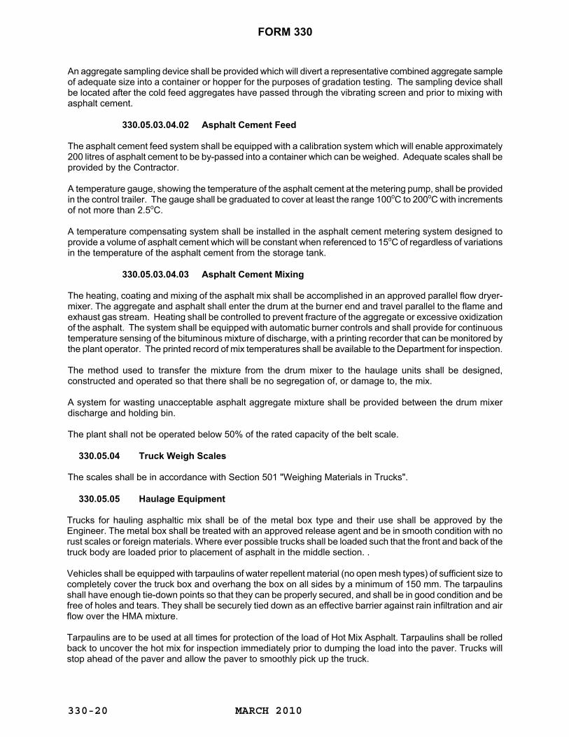
FORM 330
MARCH 2010
330-20
An aggregate sampling device shall be provided which will divert a representative combined aggregate sample of adequate size into a container or hopper for the purposes of gradation testing. The sampling device shall be located after the cold feed aggregates have passed through the vibrating screen and prior to mixing with asphalt cement.
330.05.03.04.02 Asphalt Cement Feed The asphalt cement feed system shall be equipped with a calibration system which will enable approximately 200 litres of asphalt cement to be by-passed into a container which can be weighed. Adequate scales shall be provided by the Contractor. A temperature gauge, showing the temperature of the asphalt cement at the metering pump, shall be provided in the control trailer. The gauge shall be graduated to cover at least the range 100oC to 200oC with increments of not more than 2.5oC. A temperature compensating system shall be installed in the asphalt cement metering system designed to provide a volume of asphalt cement which will be constant when referenced to 15oC of regardless of variations in the temperature of the asphalt cement from the storage tank. 330.05.03.04.03 Asphalt Cement Mixing The heating, coating and mixing of the asphalt mix shall be accomplished in an approved parallel flow dryer-mixer. The aggregate and asphalt shall enter the drum at the burner end and travel parallel to the flame and exhaust gas stream. Heating shall be controlled to prevent fracture of the aggregate or excessive oxidization of the asphalt. The system shall be equipped with automatic burner controls and shall provide for continuous temperature sensing of the bituminous mixture of discharge, with a printing recorder that can be monitored by the plant operator. The printed record of mix temperatures shall be available to the Department for inspection. The method used to transfer the mixture from the drum mixer to the haulage units shall be designed, constructed and operated so that there shall be no segregation of, or damage to, the mix. A system for wasting unacceptable asphalt aggregate mixture shall be provided between the drum mixer discharge and holding bin. The plant shall not be operated below 50% of the rated capacity of the belt scale. 330.05.04 Truck Weigh Scales The scales shall be in accordance with Section 501 "Weighing Materials in Trucks".
330.05.05 Haulage Equipment
Trucks for hauling asphaltic mix shall be of the metal box type and their use shall be approved by the Engineer. The metal box shall be treated with an approved release agent and be in smooth condition with no rust scales or foreign materials. Where ever possible trucks shall be loaded such that the front and back of the truck body are loaded prior to placement of asphalt in the middle section. . Vehicles shall be equipped with tarpaulins of water repellent material (no open mesh types) of sufficient size to completely cover the truck box and overhang the box on all sides by a minimum of 150 mm. The tarpaulins shall have enough tie-down points so that they can be properly secured, and shall be in good condition and be free of holes and tears. They shall be securely tied down as an effective barrier against rain infiltration and air flow over the HMA mixture. Tarpaulins are to be used at all times for protection of the load of Hot Mix Asphalt. Tarpaulins shall be rolled back to uncover the hot mix for inspection immediately prior to dumping the load into the paver. Trucks will stop ahead of the paver and allow the paver to smoothly pick up the truck.
FORM 330
MARCH 2010
330-21
330.05.06 Spreading Equipment Mechanical self-powered pavers shall be used which are capable of spreading the mixture true to line, grade and crown as specified and as directed by the Engineer. Pavers shall be equipped with hoppers and reversing distributing screws to place the mixture evenly in front of the screed. The distributor screws shall always be kept 1/3 to 2/3 covered. Asphalt concrete shall be dumped into the middle of the paver hopper. The hopper shall not be emptied to less than 25% of its capacity when moving except when the spreading operation is suspended. All cold or segregated asphalt must be shovelled out and wasted. In no case shall cold asphalt be allowed in the pavement mix. Pavers shall be equipped with heated vibrating screeds and shall be capable of spreading the mixture, without segregation, in thickness of from 10 mm to 200 mm and in widths of from 2500 mm to the greater of the maximum width of the project travel lane and paved shoulder combined or 4000 mm, in increments of 150 mm. The Contractor shall provide on each paver a 3 m straight edge with a level recessed in its upper surface parallel to the lower face and capable of detecting a variation from the horizontal of 3 mm in 1000 mm. The term "screed" shall mean any strike-off device operated by cutting, crowding, or other practical action which is effective on the mixture and which produces a finished surface of the evenness and texture required. The screed shall have an approved vibratory application and be adjustable as to level and crown and shall be heated in an approved manner. Pavers shall be equipped with automatic screed controls, as recommended by the paver manufacturer, for the control of longitudinal grade and transverse slope. The longitudinal grade control shall be equipped to operate from a joint matching shoe except when a spreader with ski is required by the specifications. Longitudinal joints shall be matched by the spreader with ski where ever a spreader with ski is required or specified. The transverse slope control shall be capable of operating from either side of the paver. A paver with a ski shall be required for paving base course and surface course on the Trans Canada Highway. On other projects, a paver with a ski will also be required where the contract item description includes the phrase "Spreader with Ski". The paver with a ski shall be equipped with an approved 12 m ski. Where such a ski is a flexible unit, it shall be equipped with a spring tensioned wire extending between brackets fitted on and slightly above each end of the ski. The sensing grid shall ride on the wire, not on the ski.
330.05.07 Rollers All rollers shall be of the types specifically designed for asphalt compaction. All rollers shall be in good condition and capable of reversing without backlash. They should be operated at all times by competent and experienced operators. All rollers shall be weighed in the presence of the Engineer and ballasted, if required, immediately before commencing work and whenever subsequently required by the Engineer. Steel drum rollers shall be equipped with satisfactory means to supply sufficient water to the drum to prevent adhesion of asphalt mixture. The rear wheels of combination rollers shall each be not less than 450 mm in width, drums of tandem rollers shall each be not less than 1250 mm in width. Steel drum rollers shall weigh at least 12 tonnes and shall exert a load on the compression roll of at least 6 tonnes per metre of wheel width. All pneumatic tired rollers shall be self-propelled and shall have not less than nine wheels revolving on two axles. The tires on the front and rear axles shall be staggered to cover the entire area over which the roller travels
FORM 330
MARCH 2010
330-22
with a minimum overlap of 15 mm. Under working conditions, the roller shall exert a load of not less than 5 tonnes per metre of tire width on the asphalt surface. The tires shall be inflated to an air pressure of not less than 400 kPa. The roller shall be equipped with an adequate scraping or cleaning device on each tire to prevent the bituminous mixture from accumulating on the tires. The roller shall be equipped with a water system which will keep all tires uniformly wet, and which will have a capacity that will provide not less than two hours continuous operations without refilling.
330.05.08 Material Transfer Device/Vehicle For all highway classifications, a Material Transfer Device/Vehicle shall be used at no extra cost to transfer the project’s top lift of asphalt mixture (base, leveling or surface material) from the transport vehicles to the asphalt spreader. The purpose of the Materials Transfer Device is to minimize segregation during placement of the asphalt pavement and to increase the smoothness of the pavement surface by reducing the number of stops and starts during the placement of the asphalt pavement. The Material Transfer Device shall be utilized in conjunction with a hopper insert in the asphalt spreader. The hopper insert on the asphalt paver shall be kept full at all times. Cycling the hopper wings of the asphalt paver shall be kept to a minimum. When required to pave on granulars, a self-propelled transfer vehicle is required. Prior to being utilized the Material Transfer Device/Vehicle shall be approved for use by the Engineer.
330.05.09 CONSTRUCTION 330.05.09.01 Preparation of Gravel Road Surface Where paving is to take place directly on top of a gravel surface, then the Contractor shall prepare the road to the satisfaction of the Engineer before paving. Not less than 300 m of prepared grade shall be maintained in front of the paver at all times, except at the end of the paving operation for that day. Where the top layer of Granular “A" is placed under the same contract as the paving, then the preparation of the Granular "A" prior to paving shall be carried out in accordance with Section 315 "Selected Granular Base Course". However, where the paving is to take place directly on top of materials that were not placed in the paving contract, then such preparation prior to paving as the Engineer may require shall be carried out in accordance with Section 301 "Scarifying and Reshaping".
330.05.09.02 Preparation of Old Paved Surface When required by the Engineer, old paved surfaces shall be cleaned and treated with tack coat prior to repaving with asphaltic concrete. Such treatment with tack coat as may be required shall be carried out in accordance with Section 320 "Tack Coat". 330.05.09.03 Placing of Asphaltic Courses The base on which paving is to take place shall be cleaned of all loose or foreign material before paving may take place. The asphaltic mixture shall be laid only upon a base which is dry or at least free from standing water, and when weather conditions are suitable. No paving shall take place during rain. No course shall be placed upon a previously laid course less than 12 hours after final compaction of the latter, except with the permission of the Engineer in circumstances where in his opinion this requirement would be impractical. No hot mix shall be placed unless the air temperature at the surface of the road is 7oC or above without the written permission of the Engineer. The temperature of the mixture immediately after spreading and prior to initial rolling shall not be less than 125oC.

FORM 330
MARCH 2010
330-23
The longitudinal joints in the surface course shall correspond to the demarcation between driving lanes, speed change lanes, tapers, etc. indicated in the contract or as directed by the Engineer. The width of succeeding courses shall be adjusted by an offset of width of from 150 mm to 300 mm so that longitudinal joints do not coincide. Immediately after any pavement course is laid and before roller compaction is started the surface and edges shall be checked and any irregularities adjusted by the addition or removal of mixture. Pavers must be equipped with heated vibratory screeds. There should be no allowance for pavers with non- vibratory screeds. All mechanical apparatus designed to aid compaction of the mixture shall have such devices operating continuously when the mixture is being placed unless otherwise directed by the Engineer. Where screed extensions are used, such extensions shall be designed so that the tamping or vibratory action of the screed is effectively transferred to the extensions in such manner as to provide a uniform degree of initial compaction across the full width of the freshly laid mat. To ensure continuous operation of the pavers, they shall operate at whatever speed necessary to match the output of the plant provided that a consistent and satisfactory mat is being laid. However, in no case shall the speed of the paver exceed 0.7 km/h. When two or more pavers are in echelon in order to match longitudinal joints, pavers following the lead paver shall use joint matching shoes, or an approved 12 m ski as per the contract requirements, designed for the purpose, which shall ride on the previously placed undisturbed mat. Pavers are considered to be paving in echelon when the lead paver is not more than 60 m in advance of an adjacent succeeding paver. Mixtures may be spread by hand only in places inaccessible to the paver. Hand placing shall be from a steel dump board by means of hot shovels. Hand spreading shall be with rakes of suitable design. The mixture shall be spread to the depth required to give the compacted design thickness after rolling. No loads of mixture shall leave the plant so late in the day as to preclude the spreading and compacting of the mixture during daylight. Paving of intersections, ramps and driveway tie-ins are integral with the work. No separate payment or compensation will be provided for this work.
330.05.09.04 End of Paving Season for Asphaltic Surface Course The season for laying asphaltic surface course shall end on the 30th of September each year, unless extended by the Engineer. No paving of asphaltic surface course shall take place beyond the designated end of the asphaltic surface course paving season. No pavement shall be removed from a roadway that cannot meet the requirement of replacing the asphalt before the end of the paving season. 330.05.09.05 Joints All joints shall be made in such a manner as to ensure a thorough and continuous bond and to provide a smooth riding surface. All foreign material and all loose material shall be removed from all faces against which joints are to be made. All cold faces against which joints are to be made shall be cut back to full depth to expose a fresh vertical face and painted with emulsified asphalt (tack coat). Longitudinal joints shall be rolled immediately upon placement of the fresh mixture and before the adjacent strip has completely cooled. The joint shall be set up with the back of a rake or lute at proper height and grade to receive the required compression under rolling. The depth of the newly laid mat shall be adjusted to allow for compaction. The paver shall overlap the existing mat by approximately 25 to 40 mm.
FORM 330
MARCH 2010
330-24
Prior to placing the adjacent mat, the exposed edge of each longitudinal joint must be coated with emulsified asphalt (tack coat). Upon completion of each day’s paving, the maximum length of exposed joint edge shall be 60 meters. Asphalt mat edges having companion longitudinal joints shall be matched within the maximum allotted time period as determined by the engineer. The maximum allotted time period shall be restricted to a lower limit of one hour with an upper limit of two hours. The allotted time limit will be proportioned on the paving lay-down conditions; with the lower time limit applied to least favorable placement conditions and the upper time limit applied to favorable placement conditions. Lay-down conditions considered by the engineer in establishing the time limit will include ground surface temperature, hot mix lay-down temperature, placement capacity, ultraviolet intensity, wind speed and air temperature. Longitudinal joints shall be matched by the end of each day’s operations. Unmatched asphalt longitudinal joints left exposed at the end of the day, or exposed to moisture, also shall be cut back to full depth to expose a fresh vertical face, and painted with a continuous thin coating of hot asphalt cement to the full fresh vertical face. All joints shall be constructed such that any excess material is not scattered on the surface of the freshly laid mat. Such excess material shall be carefully removed and disposed of as directed. Transverse joints shall be checked with a straight edge immediately after initial rolling. Any irregularity in the pavement surface at the joint shall immediately be corrected by the addition of or removal of mixture. When possible, the transverse joints shall be initially rolled in a direction perpendicular to the direction of paving. 330.05.09.05.01 Keyed Joints When overlaying existing asphalt concrete pavement, keyed joints shall be constructed at both ends of the project, at all intersecting roads, ramps and at all bridge decks in the repaving area. Keyed joints will only be required between the final lift of pavement and the existing pavement, unless otherwise directed by the Engineer. When existing pavement has been removed in advance of paving the joint area, the Contractor shall construct a temporary (hot mix asphalt concrete ramp) taper at the joint area to a slope of at least 50 horizontal to 1 vertical (50H:1V). Temporary tapers (ramps) shall be installed immediately following milling of the keyed joint and prior to opening the area to traffic.
330.05.09.06 General Requirements for Compaction The pavement mixture shall be compacted to a density of 92.5% of the Maximum Theoretical Density of the comparative laboratory Marshall mixture based on the criteria given in Section 330.02.02.02 "Physical Requirements for Mixture". Steel drum rollers shall have vibratory capabilities acceptable to the project engineer. Static rolling will only be allowed on bridge decks or where shallow underground utilities are present. The decision to use static rolling will be the responsibility of the project engineer. It is an express condition of this specification that all mixtures be compacted to the specified density immediately following placement. If, during the course of the paving operation, measured insitu field densities fall below the specified minimum, the Contractor shall revise his compaction process by (a) increasing the number of passes of the compaction train; (b) adjusting the frequency amplitude or tire pressure of individual rollers; or (c) by adding additional rollers to the compaction train. Steel drum rollers should operate with the drive wheel forward in the direction of paving. In all cases, the production and placing of the pavement mixture shall be controlled so that all rolling shall be completed before the pavement mat temperature falls below 80 degrees Celsius. The compaction process shall be completed before sunset. 330.05.09.06.01 Compacting Asphaltic Base, Levelling and Surface Courses Unless otherwise approved by the Engineer as per Section 330.05.09.06.02, the Contractor shall supply a minimum of two vibratory rollers and one pneumatic tired roller.

FORM 330
MARCH 2010
330-25
The initial compaction shall be obtained by the vibratory roller followed by the pneumatic tired roller. Rolling shall commence as soon after placing as the mixture will bear the roller without checking or undue displacement. Final rolling will be with a roller operating in static mode. Static rolling will be conducted only to remove any irregularities in the pavement surface. The initial breakdown rolling by a steel wheel roller shall commence as soon after placing as the mixture will bear the roller without checking or undue displacement. Rolling shall start longitudinally at the lower edge and proceed towards the higher edge of the course, overlapping on successive passes. Alternate passes of the roller shall be staggered. Intermediate rolling, using a pneumatic tire roller, shall follow the breakdown roller as closely as possible. Passes shall be so arranged as to ensure overlapping successive tire paths. The Contractor shall be responsible for ensuring that the tires are in proper condition at all times to prevent pick up of the mixture. Finishing rolling, using a steel wheel roller, shall be accomplished with the minimum number of passes required to produce a satisfactory surface. Rolling shall start longitudinally at the higher edge and proceed towards the lower edge. While rolling longitudinal joints, steel drums or rubber tires shall extend 150 mm over the previously placed mat. When paving in echelon the contactor shall provide sufficient rollers required to compact the asphalt pavement to the required degree of compaction. As a minimum there shall be four vibratory rollers and one pneumatic roller on site.
330.05.09.06.02 Compacting With Static Wheel Rollers In areas where a vibratory roller cannot operate (i.e. shallow utilities and bridge decks) compaction shall be obtained using suitable static steel wheel rollers but only under approval from the Engineer. Where approved by the Engineer (as per above) to compact the mixture using static wheel rollers, a minimum of 2 steel wheel and 1 pneumatic tire rollers will be required to operate with each paver used. The operating speed of static steel wheel rollers shall not exceed 5 km/h and shall be slow enough to avoid displacement of the mix.
330.05.09.06.03 Asphalt Density Measurement and Unit Price Adjustment
The Contractor shall be responsible for the compaction stage of the work to ensure that the density conforms to requirements. Compaction testing and unit price adjustments shall be based on daily production. Daily production is defined as the production and placement of 200 tonnes or more of asphalt concrete. If the daily production is less than 200 tonnes, the quantity for that day will be added to the next day or days in accordance with Table 1. If it is the last day of production for the project, the quantity for that day will be added to the previous day’s production. If the total quantity of asphalt mix is less than 200 tonnes for the project, two cores will be used to determine asphalt core density. Test coring must be completed prior to placement of the next lift of asphalt concrete. If the Contractor believes that certain areas to be tested should be excluded from unit price adjustments, then those areas should be identified and submitted to the Department in writing prior to the pre-paving meeting with the Department. Pavement samples will be taken on the road by Department personnel at random sample locations. Cores shall be a nominal 100 mm diameter. Sample locations will be determined by the Engineer using random sample procedures, in which the daily production is divided into segments as shown in Table 1. A
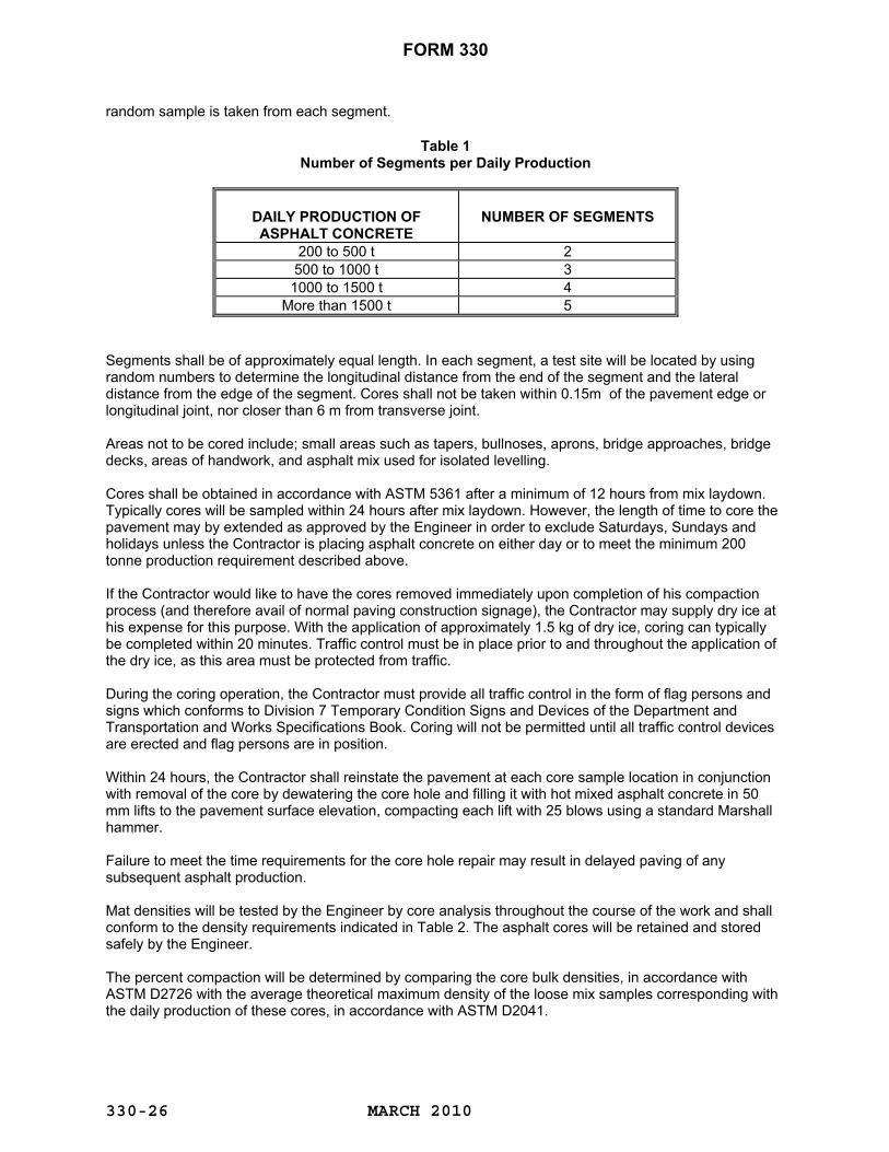
FORM 330
MARCH 2010
330-26
random sample is taken from each segment.
Table 1 Number of Segments per Daily Production
DAILY PRODUCTION OF ASPHALT CONCRETE
NUMBER OF SEGMENTS
200 to 500 t 2 500 to 1000 t 3 1000 to 1500 t 4
More than 1500 t 5
Segments shall be of approximately equal length. In each segment, a test site will be located by using random numbers to determine the longitudinal distance from the end of the segment and the lateral distance from the edge of the segment. Cores shall not be taken within 0.15m of the pavement edge or longitudinal joint, nor closer than 6 m from transverse joint. Areas not to be cored include; small areas such as tapers, bullnoses, aprons, bridge approaches, bridge decks, areas of handwork, and asphalt mix used for isolated levelling. Cores shall be obtained in accordance with ASTM 5361 after a minimum of 12 hours from mix laydown. Typically cores will be sampled within 24 hours after mix laydown. However, the length of time to core the pavement may by extended as approved by the Engineer in order to exclude Saturdays, Sundays and holidays unless the Contractor is placing asphalt concrete on either day or to meet the minimum 200 tonne production requirement described above. If the Contractor would like to have the cores removed immediately upon completion of his compaction process (and therefore avail of normal paving construction signage), the Contractor may supply dry ice at his expense for this purpose. With the application of approximately 1.5 kg of dry ice, coring can typically be completed within 20 minutes. Traffic control must be in place prior to and throughout the application of the dry ice, as this area must be protected from traffic. During the coring operation, the Contractor must provide all traffic control in the form of flag persons and signs which conforms to Division 7 Temporary Condition Signs and Devices of the Department and Transportation and Works Specifications Book. Coring will not be permitted until all traffic control devices are erected and flag persons are in position. Within 24 hours, the Contractor shall reinstate the pavement at each core sample location in conjunction with removal of the core by dewatering the core hole and filling it with hot mixed asphalt concrete in 50 mm lifts to the pavement surface elevation, compacting each lift with 25 blows using a standard Marshall hammer. Failure to meet the time requirements for the core hole repair may result in delayed paving of any subsequent asphalt production. Mat densities will be tested by the Engineer by core analysis throughout the course of the work and shall conform to the density requirements indicated in Table 2. The asphalt cores will be retained and stored safely by the Engineer. The percent compaction will be determined by comparing the core bulk densities, in accordance with ASTM D2726 with the average theoretical maximum density of the loose mix samples corresponding with the daily production of these cores, in accordance with ASTM D2041.

FORM 330
MARCH 2010
330-27
The Engineer will provide the Contractor with a copy of the results of acceptance tests within one working day of their availability. For asphaltic base and leveling courses unit price adjustments will be applied utilizing Table 2 to each tonne of asphalt mix for the day (or days if daily production is less than 200 tonne) represented by the segments cored and the percent compaction averaged. For asphaltic surface courses unit price adjustments will be applied utilizing Table 2 for each individual core’s percent of maximum theoretical, and the unit price adjustment will be applied to each tonne of asphalt mix for the day divided by the daily segments cored (or days if daily production is less than 200 tonne).
Table 2
Unit Price Adjustment for Density
% OF MAXIMUM THEORETICAL
DENSITY
UNIT PRICE
ADJUSTMENT ($ PER TONNE)
% OF MAXIMUM THEORETICAL
DENSITY
UNIT PRICE
ADJUSTMENT ($ PER TONNE)
% OF MAXIMUM THEORETICAL
DENSITY
UNIT PRICE
ADJUSTMENT ($ PER TONNE)
>98.5 REJECT 92.7 + 0.20 90.7 - 3.20 98.5 -5.00 92.6 + 0.10 90.6 - 3.60 98.4 -4.00 92.5 0.00 90.5 - 4.00 98.3 -3.00 92.4 - 0.10 90.4 - 4.40 98.2 -2.00 92.3 - 0.20 90.3 - 4.80 98.1 -1.00 92.2 - 0.30 90.2 - 5.20 98.0 -0.50 92.1 - 0.40 90.1 - 5.60 97.9 -0.40 92.0 - 0.50 90.0 - 6.00 97.8 -0.30 91.9 - 0.60 89.9 -7.00 97.7 -0.20 91.8 - 0.70 89.8 -8.00 97.6 -0.10 91.7 - 0.80 89.7 -9.00 97.5 0.00 91.6 - 0.90 89.6 -10.00 97.4 +0.10 91.5 - 1.00 89.5 -11.00 97.3 +0.20 91.4 - 1.20 89.4 -12.00 97.2 +0.30 91.3 - 1.40 89.3 -13.00 97.1 +0.40 91.2 - 1.60 89.2 -14.00
≤97.0 thru +0.50 91.1 - 1.80 89.1 -15.00 to ≥93.0 + 0.50 91.0 - 2.00 89.0 -16.00
92.9 + 0.40 90.9 - 2.40 <89.0 REJECT 92.8 + 0.30 90.8 - 2.80
330.05.09.07 Requirement for Asphaltic Leveling Course Asphaltic Leveling Course shall be used to fill surface depressions on old pavement, to restore the surface to the original profile and cross section. Patching and leveling shall not be carried out simultaneously at the same place. The patch shall be placed and fully compacted before leveling operations may proceed over the patch.
330.05.09.08 Requirements for Completed Asphaltic Base and Surface Courses Each course, after final compaction shall be smooth, true to the established crown and grade, shall have the average thickness specified, and shall at no point vary more than 6 mm from the specified thickness. The surfaces of each base course, and any surface not subjected to smoothness testing under Section 330.07.10, shall be free from deviations exceeding 3 mm as measured with a 3 m straight edge paralleling the centerline of the roadway. Any low or defective locations shall immediately be remedied by removal of the defective area by cutting and replacing it with fresh hot asphalt. The area should be tacked and allowed to cure prior to the placement of any new asphalt. The new asphalt shall immediately be compacted to conform to the surrounding area and be thoroughly bonded to it.
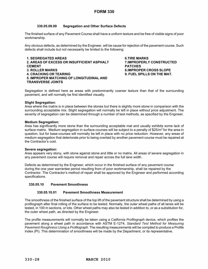
FORM 330
MARCH 2010
330-28
330.05.09.09 Segregation and Other Surface Defects The finished surface of any Pavement Course shall have a uniform texture and be free of visible signs of poor workmanship. Any obvious defects, as determined by the Engineer, will be cause for rejection of the pavement course. Such defects shall include but not necessarily be limited to the following:
1. SEGREGATED AREAS 2. AREAS OF EXCESS OR INSUFFICIENT ASPHALT CEMENT 3. ROLLER MARKS 4. CRACKING OR TEARING 5. IMPROPER MATCHING OF LONGITUDINAL AND TRANSVERSE JOINTS
6.TIRE MARKS 7.IMPROPERLY CONSTRUCTED PATCHES 8.IMPROPER CROSS SLOPE 9. FUEL SPILLS ON THE MAT.
Segregation is defined here as areas with predominantly coarser texture than that of the surrounding pavement, and will normally be first identified visually. Slight Segregation: Area where the matrix is in place between the stones but there is slightly more stone in comparison with the surrounding acceptable mix. Slight segregation will normally be left in place without price adjustment. The severity of segregation can be determined through a number of test methods, as specified by the Engineer. Medium Segregation: Area has significantly more stone than the surrounding acceptable mat and usually exhibits some lack of surface matrix. Medium segregation in surface-courses will be subject to a penalty of $25/m2 for the area in question, but for base-courses will normally be left in place with no price reduction. However, any areas of medium segregation that deteriorate prior to being overlaid by another pavement course must be repaired at the Contractor’s cost. Severe segregation: Area appears very stony, with stone against stone and little or no matrix. All areas of severe segregation in any pavement course will require removal and repair across the full lane width. Defects as determined by the Engineer, which occur in the finished surface of any pavement course during the one year warrantee period resulting from of poor workmanship, shall be repaired by the Contractor. The Contractor’s method of repair shall be approved by the Engineer and performed according specifications. 330.05.10 Pavement Smoothness 330.05.10.01 Pavement Smoothness Measurement The smoothness of the finished surface of the top lift of the pavement structure shall be determined by using a profilograph after final rolling of the surface to be tested. Normally, the outer wheel paths of all lanes will be tested, in 100 m sections, or lots. Other wheel paths may also be tested in addition to, or as a substitution for, the outer wheel path, as directed by the Engineer. The profile measurements will normally be taken using a California Profilograph device, which profiles the pavement along a wheel path in accordance with ASTM E-1274, Standard Test Method for Measuring Pavement Roughness Using a Profilograph. The resulting measurements will be compiled to produce a Profile Index (PI). This determination of smoothness will be made by the Department, or its representative.

FORM 330
MARCH 2010
330-29
The Profile Index (PI) for each lane is the cumulative profile reading of the outer wheel path in millimeters per 100 m section, in excess of the 5 mm blanking band. 330.05.10.02 Profile Index Limits The surface of the profiled pavement shall conform to the following Smoothness requirements:
Table 5 – Smoothness Requirements
Roadway Alignment Section
Profile Index (mm /
100 m) RLU-80 CLASSIFICATION AND ABOVE
15 mm OR LESS
INTERCHANGE RAMPS, TAPERS*, AND HIGHWAYS OF LOWER CLASSIFICATION THAN RLU-80
N/A
If the Smoothness requirements are not met, the Contractor shall repair the sections, or pay a price adjustment based on the Profile Index. These price adjustments will be applied based on the square meters of the final pavement surface as outlined in Table 6. For price adjustment purposes, the width of the final pavement surface includes the driving lane and adjacent shoulders.
Table 6 Profile Index Price Adjustment Schedule
PROFILE INDEX PI (
mm / 100m)
PRICE ADJUSTMENT $ PER
SQUARE METER
PROFILE INDEX PI (
mm / 100m)
PRICE ADJUSTMENT $ PER
SQUARE METER
< 4.0
$0.338
18.1 to 21.0
-$0.540 4.1 to 5.5 incl.
$0.270
21.1 to 22.5
-$0.810
5.6 to 7.0
$0.203
22.6 to 24.0
-$1.080 7.1 to 8.5
$0.135
24.1 to 25.5
-$1.350
8.6 to 10.0
$0.068
25.6 to 27.0
-$1.620 10.1 to 15.0
$0.00
27.1 to 28.5
-$1.890
15.1 to 18.0
-$0.270
28.6 to 30.0
-$2.160 EACH ADDITIONAL 1.5mm INCREMENT ABOVE 30.0
-(NO OF INCREMENTS X $0.54 +$2.160)
330.05.10.03 Surface Deviations (Individual Bumps and Dips) Individual bumps and dips shall not exceed 8 mm in 7.6 m in the vertical direction as measured by the Profilograph. Where individual bumps and dips exceed 8 mm in 7.6 m, they may be corrected or the Contractor may elect to accept a penalty as per Table 7. The 5 mm blanking band is not applied to the bump and dip measurements. Not withstanding, transverse joints are still subject to Section 330.05.09.05 and any irregularity should be immediately corrected.
Table 7 Bump and Dip Penalties
Bumps / Dips Measured in the Vertical Direction
Penalty
Bumps / Dips Measured in the
Vertical Direction Penalty
8.1 - 9 mm
$ 200
13.1 - 14 mm
$1200 9.1 - 10 mm
$ 400
14.1 - 15 mm
$1400

FORM 330
MARCH 2010
330-30
10.1 - 11 mm $ 600 15.1 - 16 mm $1600 11.1 - 12 mm
$ 800
16.1 - 17 mm
$1800
12.1 - 13 mm
$1000
17.1 - 18 mm
$2000 Each Additional 1 mm Increment Above 18 mm
(No. of Increments x $500) + $2000
330.05.10.04 Testing Testing and Evaluation: Profilograph testing will be performed as soon as possible after final rolling of the surface. Profile measurements will terminate 15 metres from the end of each bridge deck, or from a joint between existing pavement and the new pavement. Profiles will be taken at approximately the outer wheel path for every lane of traffic, or as designated by the Engineer. Repeat profiles may be taken only to define the limits of an out-of-tolerance surface variation. Some sections may be omitted from testing, as determined by the Engineer. Tapers will be excluded from testing unless otherwise directed by the Engineer. The Contractor shall give the Department at least 5 days notice prior to laying the final course of asphalt. A pre-paving meeting shall be convened on-site between the Contractor, the Engineer, and the Manager of Materials (or their representatives) to discuss any concerns either party might have regarding placement of the final course of asphalt. If the Contractor believes certain areas to be tested should be excluded from price adjustments, then those concerns should be submitted in writing for discussion at that meeting. Failure to submit those concerns in writing shall mean all areas shall be subject to price adjustments. Re-testing to Verify Original Testing Results: Should the Contractor request retesting of pavement sections due to an excessive PI or excessive bump and dip heights, and the Department approves the re-test, then the Contractor shall bear all costs associated with testing if the original results are confirmed. If the retest results determine an improved PI or improved bump and dip heights over the original test, then testing costs shall be borne equally by the Contractor and the Department, and the average of the two results will be accepted as final. Only one retest, using the same profilograph is permitted. 330.05.10.05 Remedial Action Where the Profile Index (PI) and / or the bump and dip heights are greater than the limits specified, then the Contractor may elect to correct the smoothness of the deficient sections by i) rolling, ii) cold milling and replacing, iii) overlaying, or iv) removing and replacing. Remedial Action Plan: Prior to initiating any remedial work, the Contractor shall submit to the Engineer for approval a detailed plan outlining the methods to be used to improve the smoothness. All remedial actions shall be done at the Contractor’s expense, and shall comply with the following requirements: Rolling: Additional rolling will only be permitted while asphalt is still workable, i.e., during the same day’s paving operations, and at the sole direction of the Engineer. Additional rolling may be used only to correct deviations in transverse joints or excessive bump and dip deviations. Rolling shall not be used solely to reduce the overall PI of a section - rolling is to be used only for correction of individual bumps and dips, not 100 m sections or lots. Rolling must not cause any damage, such as but not limited to, crushing, cracking, or displacing the asphalt concrete. Should the rolling cause damage, the Contractor shall remove and replace the damaged area, at his expense. Cold Milling and Replacing: Any section to be repaired by cold milling and replacing shall be milled the full lane width and a minimum length of 20 meters, to the full thickness of the lift of asphalt to be replaced. All replacement asphalt concrete shall be of the same material and mix design as originally used on the section undergoing repairs.

FORM 330
MARCH 2010
330-31
Materials removed by cold milling shall become the property of the Contractor. Overlaying: When an additional lift of asphalt concrete is used to improve smoothness, it shall extend the full width of the pavement surface and have a finished compacted thickness sufficient to produce compliance with smoothness limits, and produce a uniform final surface closely matching the existing asphalt pavement. Butt joints will be required at each end of the overlay. All asphalt concrete used for overlay shall be of the same material and mix design as originally used on the section undergoing repairs. Removing and Replacing: Where the remedial action involves removal and replacement, the lift shall be removed to its full thickness and lane width. All asphalt removed shall become the property of the Contractor. Asphalt concrete shall be replaced to its original thickness and shall be of the same material and mix design as used originally in the section to be replaced. Retesting Following Remedial Action: Where Remedial Action is conducted, then the Contractor shall bear all costs associated with the verification of smoothness of the remedial work. The test results of the remedial work shall be accepted as final and replace the initial test results for price adjustment purposes. Time Limits for Remedial Action: All remedial work should be completed within 30 days of receipt by the Contractor of Profilograph testing results, but in no case later than September 30. 330.05.11 ASPHALTIC PATCHING Asphaltic patching involves patching pot holes in bituminous pavement, patching cuts for culverts or patching transverse cracks with hot mix asphaltic concrete. Holes to be patched shall have loose material removed and be cleaned of dirt and gravel. Tack coat shall be applied to all edges to be repaired. Surfaces shall be thoroughly dry before tack coat is applied. Asphaltic concrete for use in patching shall conform to the requirements of Asphaltic Surface Course or Asphaltic Leveling Course Type I. Asphaltic concrete shall be placed and leveled in the hole in one lift, so that when compacted, the repaired hole is level with the surrounding surface. The patches shall be compacted in accordance with the requirements of 330.05.09.06 "General Requirements for Compaction".
330.05.12 MEASUREMENT FOR PAYMENT 330.05.12.01 Measurement for Payment for Asphaltic Surface, Asphaltic Base Course,
Asphaltic Leveling Courses Type I and Type II Measurement for payment will only be made for those materials accepted for use under this specification and then only when incorporated into the work at the required locations. Measurement for payment for the particular type of asphaltic course shall be by the weight of that material in tonnes, rounded to one decimal place. Payment Adjustment Factors, if applicable, shall be as described throughout this specification. The material shall be weighed by means of the truck scales. The Department will supply scale tickets and the Department
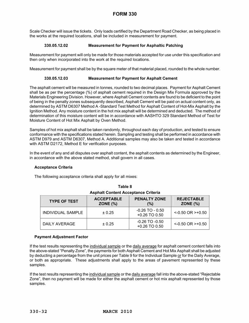
FORM 330
MARCH 2010
330-32
Scale Checker will issue the tickets. Only loads certified by the Department Road Checker, as being placed in the works at the required locations, shall be included in measurement for payment.
330.05.12.02 Measurement for Payment for Asphaltic Patching Measurement for payment will only be made for those materials accepted for use under this specification and then only when incorporated into the work at the required locations. Measurement for payment shall be by the square meter of that material placed, rounded to the whole number.
330.05.12.03 Measurement for Payment for Asphalt Cement The asphalt cement will be measured in tonnes, rounded to two decimal places. Payment for Asphalt Cement shall be as per the percentage (%) of asphalt cement required in the Design Mix Formula approved by the Materials Engineering Division. However, where Asphalt Cement contents are found to be deficient to the point of being in the penalty zones subsequently described, Asphalt Cement will be paid on actual content only, as determined by ASTM D6307 Method A -Standard Test Method for Asphalt Content of Hot-Mix Asphalt by the Ignition Method. Any moisture content in the hot mix asphalt will be determined and deducted. The method of determination of this moisture content will be in accordance with AASHTO 329 Standard Method of Test for Moisture Content of Hot Mix Asphalt by Oven Method. Samples of hot mix asphalt shall be taken randomly, throughout each day of production, and tested to ensure conformance with the specifications stated herein. Sampling and testing shall be performed in accordance with ASTM D979 and ASTM D6307, Method A. Additional samples may also be taken and tested in accordance with ASTM D2172, Method E for verification purposes. In the event of any and all disputes over asphalt content, the asphalt contents as determined by the Engineer, in accordance with the above stated method, shall govern in all cases.
Acceptance Criteria
The following acceptance criteria shall apply for all mixes:
Table 8 Asphalt Content Acceptance Criteria
TYPE OF TEST ACCEPTABLE ZONE (%)
PENALTY ZONE (%)
REJECTABLE ZONE (%)
INDIVIDUAL SAMPLE ± 0.25 -0.26 TO - 0.50 +0.26 TO 0.50 <-0.50 OR >+0.50
DAILY AVERAGE ± 0.25 -0.26 TO -0.50 +0.26 TO 0.50 <-0.50 OR >+0.50
Payment Adjustment Factor
If the test results representing the individual sample or the daily average for asphalt cement content falls into the above-stated “Penalty Zone”, the payments for both Asphalt Cement and Hot Mix Asphalt shall be adjusted by deducting a percentage from the unit prices per Table 9 for the Individual Sample or for the Daily Average, or both as appropriate. These adjustments shall apply to the areas of pavement represented by these samples. If the test results representing the individual sample or the daily average fall into the above-stated “Rejectable Zone”, then no payment will be made for either the asphalt cement or hot mix asphalt represented by those samples.
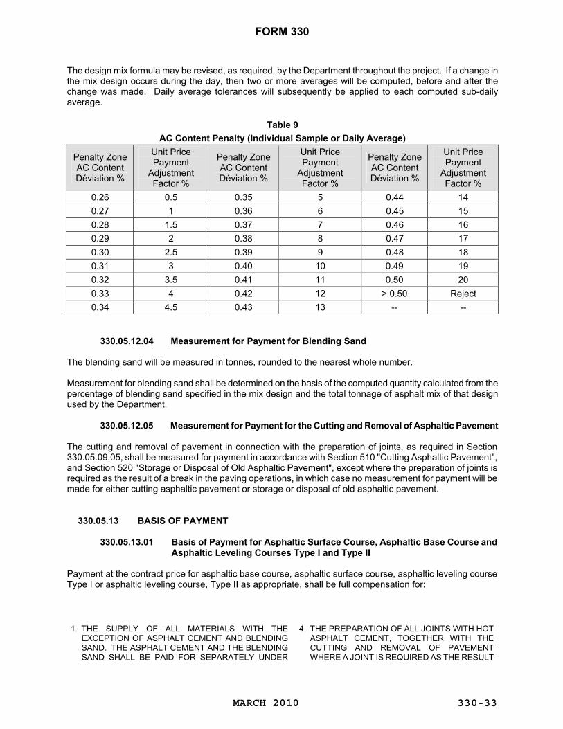
FORM 330
MARCH 2010
330-33
The design mix formula may be revised, as required, by the Department throughout the project. If a change in the mix design occurs during the day, then two or more averages will be computed, before and after the change was made. Daily average tolerances will subsequently be applied to each computed sub-daily average.
Table 9 AC Content Penalty (Individual Sample or Daily Average)
Penalty Zone AC Content Déviation %
Unit Price Payment
Adjustment Factor %
Penalty Zone AC Content Déviation %
Unit Price Payment
Adjustment Factor %
Penalty Zone AC Content Déviation %
Unit Price Payment
Adjustment Factor %
0.26 0.5 0.35 5 0.44 14 0.27 1 0.36 6 0.45 15 0.28 1.5 0.37 7 0.46 16 0.29 2 0.38 8 0.47 17 0.30 2.5 0.39 9 0.48 18 0.31 3 0.40 10 0.49 19 0.32 3.5 0.41 11 0.50 20 0.33 4 0.42 12 > 0.50 Reject 0.34 4.5 0.43 13 -- --
330.05.12.04 Measurement for Payment for Blending Sand The blending sand will be measured in tonnes, rounded to the nearest whole number. Measurement for blending sand shall be determined on the basis of the computed quantity calculated from the percentage of blending sand specified in the mix design and the total tonnage of asphalt mix of that design used by the Department.
330.05.12.05 Measurement for Payment for the Cutting and Removal of Asphaltic Pavement The cutting and removal of pavement in connection with the preparation of joints, as required in Section 330.05.09.05, shall be measured for payment in accordance with Section 510 "Cutting Asphaltic Pavement", and Section 520 "Storage or Disposal of Old Asphaltic Pavement", except where the preparation of joints is required as the result of a break in the paving operations, in which case no measurement for payment will be made for either cutting asphaltic pavement or storage or disposal of old asphaltic pavement.
330.05.13 BASIS OF PAYMENT 330.05.13.01 Basis of Payment for Asphaltic Surface Course, Asphaltic Base Course and
Asphaltic Leveling Courses Type I and Type II Payment at the contract price for asphaltic base course, asphaltic surface course, asphaltic leveling course Type I or asphaltic leveling course, Type II as appropriate, shall be full compensation for: 1. THE SUPPLY OF ALL MATERIALS WITH THE
EXCEPTION OF ASPHALT CEMENT AND BLENDING SAND. THE ASPHALT CEMENT AND THE BLENDING SAND SHALL BE PAID FOR SEPARATELY UNDER
4. THE PREPARATION OF ALL JOINTS WITH HOT
ASPHALT CEMENT, TOGETHER WITH THE CUTTING AND REMOVAL OF PAVEMENT WHERE A JOINT IS REQUIRED AS THE RESULT
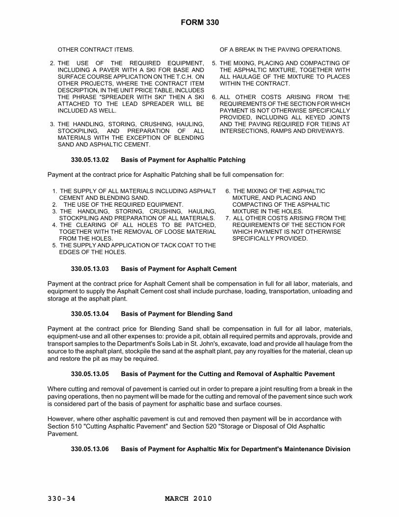
FORM 330
MARCH 2010
330-34
OTHER CONTRACT ITEMS. 2. THE USE OF THE REQUIRED EQUIPMENT,
INCLUDING A PAVER WITH A SKI FOR BASE AND SURFACE COURSE APPLICATION ON THE T.C.H. ON OTHER PROJECTS, WHERE THE CONTRACT ITEM DESCRIPTION, IN THE UNIT PRICE TABLE, INCLUDES THE PHRASE "SPREADER WITH SKI" THEN A SKI ATTACHED TO THE LEAD SPREADER WILL BE INCLUDED AS WELL.
3. THE HANDLING, STORING, CRUSHING, HAULING,
STOCKPILING, AND PREPARATION OF ALL MATERIALS WITH THE EXCEPTION OF BLENDING SAND AND ASPHALTIC CEMENT.
OF A BREAK IN THE PAVING OPERATIONS. 5. THE MIXING, PLACING AND COMPACTING OF
THE ASPHALTIC MIXTURE, TOGETHER WITH ALL HAULAGE OF THE MIXTURE TO PLACES WITHIN THE CONTRACT.
6. ALL OTHER COSTS ARISING FROM THE
REQUIREMENTS OF THE SECTION FOR WHICH PAYMENT IS NOT OTHERWISE SPECIFICALLY PROVIDED, INCLUDING ALL KEYED JOINTS AND THE PAVING REQUIRED FOR TIEINS AT INTERSECTIONS, RAMPS AND DRIVEWAYS.
330.05.13.02 Basis of Payment for Asphaltic Patching
Payment at the contract price for Asphaltic Patching shall be full compensation for:
1. THE SUPPLY OF ALL MATERIALS INCLUDING ASPHALT CEMENT AND BLENDING SAND.
2. THE USE OF THE REQUIRED EQUIPMENT. 3. THE HANDLING, STORING, CRUSHING, HAULING,
STOCKPILING AND PREPARATION OF ALL MATERIALS. 4. THE CLEARING OF ALL HOLES TO BE PATCHED,
TOGETHER WITH THE REMOVAL OF LOOSE MATERIAL FROM THE HOLES.
5. THE SUPPLY AND APPLICATION OF TACK COAT TO THE EDGES OF THE HOLES.
6. THE MIXING OF THE ASPHALTIC
MIXTURE, AND PLACING AND COMPACTING OF THE ASPHALTIC MIXTURE IN THE HOLES.
7. ALL OTHER COSTS ARISING FROM THE REQUIREMENTS OF THE SECTION FOR WHICH PAYMENT IS NOT OTHERWISE SPECIFICALLY PROVIDED.
330.05.13.03 Basis of Payment for Asphalt Cement
Payment at the contract price for Asphalt Cement shall be compensation in full for all labor, materials, and equipment to supply the Asphalt Cement cost shall include purchase, loading, transportation, unloading and storage at the asphalt plant.
330.05.13.04 Basis of Payment for Blending Sand Payment at the contract price for Blending Sand shall be compensation in full for all labor, materials, equipment-use and all other expenses to: provide a pit, obtain all required permits and approvals, provide and transport samples to the Department's Soils Lab in St. John's, excavate, load and provide all haulage from the source to the asphalt plant, stockpile the sand at the asphalt plant, pay any royalties for the material, clean up and restore the pit as may be required.
330.05.13.05 Basis of Payment for the Cutting and Removal of Asphaltic Pavement
Where cutting and removal of pavement is carried out in order to prepare a joint resulting from a break in the paving operations, then no payment will be made for the cutting and removal of the pavement since such work is considered part of the basis of payment for asphaltic base and surface courses. However, where other asphaltic pavement is cut and removed then payment will be in accordance with Section 510 "Cutting Asphaltic Pavement" and Section 520 "Storage or Disposal of Old Asphaltic Pavement.
330.05.13.06 Basis of Payment for Asphaltic Mix for Department's Maintenance Division
FORM 330
MARCH 2010
330-35
The Department's Maintenance Division may, on occasion have need for asphalt in the areas of a project. The Contractor will allow Department trucks along with his own trucks to pick up asphalt from the plant as required. Payment will be made to the Contractor by the tonne weighed over the scales and invoiced to the Department based on the tendered unit price in the Contract except in cases where the Contractor has a Standing Offer Agreement with the Department for supply of asphalt and the Unit Price in the Standing Offer Agreement is less than the Unit Price Table in the highway contract, then the Unit Price in the Standing Offer Agreement will apply.
330.05.13.07 Basis of Payment for Rejected Mix The Department will pay for only the original mix quantity. The Contractor is fully responsible to bear all costs associated with repair of rejected areas, including all materials, equipment, plant, labour, traffic control and incidentals necessary to complete the work to the satisfaction of Engineer. If the Department determines the rejected material may remain in the work, and the Contractor elects not to repair the affected area, payment for the rejected mix components will be at 50% of the various contract unit prices.
330.06 END PRODUCT SPECIFICATION (EPS) FOR ASPHALT CONCRETE MIX – HOT PLACED
330.06.01 General This item consists of supplying crushed aggregates, blending materials, anti-stripping agent, asphalt binder, and the production, loading, hauling, placing and compaction of hot mix asphalt concrete. The limits of placement, application rates and the asphalt concrete mixture type shall be as stated in the contract specifications. Areas constructed will be subjected to various quality assurance testing.
It shall be the Contractor’s responsibility to provide an acceptable product as specified. In order to achieve this, the Contractor shall implement and maintain a quality control system that will provide assurance that all components, as well as end result products, submitted to the Department for acceptance, conform to the contract requirements. This is without regard to whether the products are manufactured by the Contractor or purchased from suppliers or subcontractors. The Contractor’s Quality Control System proposed for each project shall be provided to the Department in the form of a written Quality Control plan. Quality assurance tests shall be performed, by the Department, on random samples taken either at the production site or lay down site.
330.06.02 Definitions
330.06.02.01 End Product Specification (EPS) An end product specification is a specification under which the Contractor has control of the processes that produce the items of construction. The Department accepts or rejects the end product according to identified bonus / penalty items. The Contractor is entirely responsible for quality control. End product acceptance is the responsibility of the Department based on a program of quality assurance testing.
330.06.02.02 Design Mix Formula (DMF) The DMF is defined as the laboratory determination of the precise proportions of asphalt binder, additives and aggregates to be blended together to meet the specified properties for a given asphalt concrete mix.
330.06.02.03 Job Mix Formula (JMF)

FORM 330
MARCH 2010
330-36
The JMF is the resultant establishment of the single definite percentage for each sieve fraction of aggregate and asphalt binder content that will produce the desired asphalt concrete mix properties under field conditions.
330.06.02.04 Actual Asphalt Binder Content This is the percentage of asphalt binder in the asphalt concrete mixture, determined from quality assurance testing in accordance with ASTM D6307.
330.06.02.05 Lot For each mixture type specified, a Lot is defined as the quantity of asphalt concrete plant production, to a total of 1600 tonnes, where approved changes to the Job Mix Formula have not occurred. For loose samples, each Lot shall be divided into 4 (four) approximately equal segments and one loose sample is randomly selected from each segment. For core samples, each Lot shall be divided into 4 (four) approximately equal segments and three adjacent core samples are taken from each segment at a single random location. If it is the last time the mix is produced and this criterion cannot be met (i.e. less than 1600 tonnes of mix remain), the following shall apply:
• If the remaining plant production is 400 tonnes or less, the production will be added to the previous Lot. The adjusted Lot shall be divided into 5 (five) approximately equal segments and one loose sample is randomly selected from each segment. For core samples, the adjusted Lot shall be divided into 4 (four) approximately equal segments and three adjacent core samples are taken from each segment at a single random location.
• If the remaining plant production is between 400 and 800 tonnes, the production will be added to the
previous Lot. The adjusted Lot shall be divided into 6 (six) approximately equal segments and one loose sample is randomly selected from each segment. For core samples, the adjusted Lot shall be divided into 4 (four) approximately equal segments and three adjacent core samples are taken from each segment at a single random location.
• If the remaining plant production is greater than 800 tonnes, but less than 1600 tonnes, the production
will be designated as a separate Lot. The separate Lot shall be divided into 4 (four) approximately equal segments and one loose sample is randomly selected from each segment. For core samples, the adjusted Lot shall be divided into 4 (four) approximately equal segments and three adjacent core samples are taken from each segment at a single random location.
In all cases above, the lot size shall be equally segmented and random samples selected from each segment. A separate Lot will be established at the discretion of the Engineer if conditions of construction indicate that it is likely that a portion of the Lot production is significantly different from the remainder of the Lot production. 330.06.02.06 Stratified Random Sample A stratified random sample is defined as a representative sample taken in an unbiased manner, by dividing a Lot into approximately equal segments. A random sample is taken from each area or segment.
330.06.02.07 Sample Mean This is the arithmetic mean of the group of test results derived from the randomly selected samples.
330.06.02.08 Mean of the Deviations

FORM 330
MARCH 2010
330-37
This is the sum of the absolute values of the deviations divided by the number of tests in the Lot.
330.06.02.09 Thickness Thickness is defined as the specified application rate indicated in the contract documents divided by the average bulk relative density obtained from the core samples for a given Lot. Price adjustments for thickness will be applied to new construction only.
330.06.02.10 Mix Property Mix properties measured for product acceptance and price adjustments are as follows: Gradation: Passing 4.75 mm and 75 μm sieves, Asphalt Binder Content, Binder Grade, Marshall Air Voids, Thickness, Application Rate, Density and Smoothness.
330.06.02.11 Referee Sample A referee sample is defined as the portion of the loose or core sample that is set aside by the Department representative’s laboratory in the case of an appeal of binder content, gradation, and/or density by the Contractor.
330.06.03 Materials
330.06.03.01 General All materials required to produce the asphalt concrete will be supplied by the contractor. Details regarding the property requirements for the asphalt cement, course aggregate, fine aggregate, blending sand, anti-stripping admixtures are presented in section 330.02. 330.06.04 Mix Design Requirements 330.06.04.01 Establishing a Design Mix Formula (DMF)
Preparation and submission of the asphalt DMF for the Department’s approval is the responsibility of the Contractor. The Contractor shall use professional engineering services and a qualified testing laboratory, to assess the aggregate materials, asphalt binders, blending sands, mineral fillers and anti-stripping agents proposed for use and to carry out the design of the asphalt concrete mix.
330.06.04.02 Requirements for Design Mix Formula The asphalt mix design shall follow the Marshall method of the DMF as outlined in the latest edition of the Asphalt Institute Manual Series No. 2 (MS-2). The mix design, at the design asphalt binder content, shall meet the requirements presented in section 330.02 for each asphalt concrete mix specified. The Design Air Voids shall be chosen as the lowest value, within the range of 3.5 to 4.0% inclusive, such that all other mix design criteria are met.
330.06.04.03 Submission of Design Mix Formula The Contractor’s submission shall include the following information/materials:
• The specific gravity and the percentage by mass of each aggregate (including natural sand, lime) to be used in the mix.
• The mix design gradation of the combined aggregate (including natural sand, lime). • Physical properties of the aggregates specified, in accordance with Section 330.02.

FORM 330
MARCH 2010
330-38
• All Marshall mix design characteristics, including graphs used in arriving at the final mix design, the bulk relative density of the combined aggregates, and the asphalt absorption of the combined aggregates.
• Pit identification consisting of its name, name of owner, public highway from which it is accessed.
330.06.04.04 Evaluation of Design Mix Formula The Engineer will require up to ten (10) working days from the time of receipt of the DMF, for evaluation by the Department and/or the Department’s representative’s laboratory. The Engineer will advise the Contractor of the acceptability. If the DMF does not meet the requirements of Section 330.02, it shall be rejected. The Engineer shall provide a written explanation to the Contractor that details why the DMF failed. The Contractor shall then provide another complete DMF in accordance with 330.06.04.02 Requirements for Design Mix Formula, and re-submit it to the Engineer for evaluation. Each time a DMF is re-submitted, an additional five (5) working days, from the time of receipt of the revised DMF, shall be required for evaluation by the Department and/or the Department’s representative’s laboratory. The Engineer will not accept any asphalt concrete mix produced prior to the Contractor receiving written approval of the DMF from the Engineer.
330.06.04.05 Establishing a Job Mix Formula (JMF)
The Contractor shall establish a JMF for each mix type by placing a specified quantity of trial mix (asphalt concrete) at a location designated by the Engineer. The maximum allotted quantity of asphalt concrete allowed for establishment of the JMF is as follows:
• Base Course: 600 tonnes • Surface Course: 300 tonnes • Alternatively, the Contractor may elect to waive their trial mix option and submit their JMF (and
supporting documentation) directly to the Engineer for approval.
At the discretion of the Engineer, the Contractor may be permitted to carry over any unused portion of the base course allotment to supplement the surface course allotment. The asphalt concrete placed in the trial sections will be tested with a minimum of 3 QC tests to determine if it meets the requirements of Section 330.02, however, unit price adjustments and repair/replace/reject criteria will be applied to the Thickness and Density properties. The asphalt concrete shall be assessed for surface defects in accordance with 330.06.07 Surface Defects.
330.06.04.06 Approval of Job Mix Formula The Contractor shall submit the JMF in writing to the Engineer for approval. The Contractor’s submission shall include the following information:
• The percentage by mass of each aggregate (including natural sand, lime) to be used in the mix • The JMF target asphalt binder content and gradation • The % Air Voids, Voids in Mineral Aggregate (VMA) and Voids Filled with Asphalt (VFA) from the trial
mix.
The Engineer’s written approval of the JMF will allow the Contractor to start/continue production. Rejection of the JMF shall require the appropriate action based on the Engineer’s assessment.
330.06.04.07 Field Adjustments to the Job Mix Formula.
A field adjustment to the JMF is defined as a change in the target gradation, asphalt binder content and/or proportioning of various aggregate sizes, within specified limits (when compared to the original JMF) as follows, without a redesign of the mix.
FORM 330
MARCH 2010
330-39
• ± 0.2% in asphalt content • ± 5.0% in RAP proportion • ± 5.0% passing the 19.0 mm sieve • ± 4.0% passing the 12.7 and 9.5 mm sieves • ± 3.0% passing the 4.75 and 2.00 mm sieves • ± 2.0% passing the 0.425 and 0.150 mm sieves • ± 1.0% passing the 0.075 mm sieve
The Contractor shall request JMF changes in writing, including supporting test results (a minimum of 3 sets of QC results as per 330.06.04.05 Establishing a Job Mix Formula). Upon approval by the Engineer in writing, revisions to the JMF will be applied to subsequent Lots only. In no case will changes to the JMF be accepted during production of a Lot. The Department will limit the number of field adjustments to the originally approved JMF to two.
The Contractor shall submit a revised DMF in accordance with 330.06.04.02 Requirements for Design Mix Formula, for the following changes:
• A change in the source of asphalt cement used in the asphalt concrete mix. • A change in the source of the aggregate used in the asphalt concrete mix. • A change in material (different aggregate sizes) from the same source. • A change in the percentage of the aggregate components from that established in the JMF. • A change in the asphalt cement content from that established in the JMF • A change in the source of the anti-strip additive used in the asphalt concrete mix.
330.06.05 Construction Methods
330.06.05.01 General Equipment shall be designed and operated to produce an end product complying with the requirements of this specification. Equipment used shall be of adequate rated capacity and shall be in good working order.
330.06.05.02 Production The asphalt mixing plant and its components shall meet the requirements of ASTM D 995 Standard Specification for Mixing Plants for Hot-Mixed, Hot-Laid Bituminous Paving Mixtures. Asphalt concrete exceeding a temperature of 1650C at any point of the operation shall be cause for rejection.
330.06.05.03 Transportation
Vehicles shall be equipped with tarpaulins of water repellent material (no open mesh types) of sufficient size to completely cover the truck box and overhang the box on all sides by a minimum of 150 mm. The tarpaulins shall have enough tie-down points so that they can be properly secured, and shall be in good condition and be free of holes and tears. They shall be securely tied down as an effective barrier against rain infiltration and air flow over the HMA mixture. Tarpaulins are to be used at all times for protection of the load of Hot Mix Asphalt. Tarpaulins shall be rolled back to uncover the hot mix for inspection immediately prior to dumping the load into the paver. Trucks will stop ahead of the paver and allow the paver to smoothly pick up the truck.
FORM 330
MARCH 2010
330-40
Asphalt concrete shall be transported from the paving plant to the work site in trucks that are properly equipped and in good working order. The use of hydrocarbon fuels or solvents to lubricate the truck bodies or to clean tools or equipment, will not be permitted. A biodegradable release agent shall be supplied by the Contractor to clean or lubricate tools, equipment and truck bodies.
330.06.05.04 Placement The Contractor shall not place asphalt concrete during rain, or when the surface is frozen, nor when the pavement surface shows signs of free-standing water or when the air temperature at surface is below 70C. A Material Transfer Device/Vehicle shall be used at no extra cost to transfer the asphalt mixture from the transport vehicles to the asphalt spreader. Asphalt concrete shall be placed upon a prepared surface which is free of any loose or foreign material. The asphalt concrete shall be spread by a mechanical self-powered paver capable of achieving the specified grade, line and crown. Placement of asphalt concrete shall only be conducted during daylight hours, unless specifically noted otherwise in the contract specifications. Contact edges of existing mats and contact faces of curbs, gutters, manholes, sidewalks bridge structures, as well as any new mat joint having a temperature less than 600C shall be coated with a thin film of tack before placing the asphalt concrete. Failed areas in existing surfaces (paved or gravel) shall be repaired, as directed by the Engineer. Areas requiring repair will be identified by the Engineer in consultation with the Contractor. Irregularities in the horizontal alignment and grade along the outside edge of the asphalt concrete shall be corrected by the addition or removal of mix before the edge is rolled. Paving of intersections, extra widths and other variations from standard lane alignment and as defined in the contract, whether by hand spreading or machine laying, shall be carried out concurrently with the machine laying operation of the regular mat, unless otherwise approved by the Engineer. Fuel spills from the Contractor’s equipment shall be immediately repaired by the Contractor to the satisfaction of the Engineer. Paving of intersections, ramps and driveway tie-ins are integral with the work. No separate payment or compensation will be provided for this work. 330.06.05.05 Joint Construction All joints shall be constructed to ensure a dense, well-bonded, continuous seal and to provide a smooth riding surface. 330.06.05.05.01 Transverse Construction Joints Transverse joints shall be butt joints constructed at the end of each day’s work and at other times when paving is halted for a period of time which results in the asphalt concrete cooling to below 120°C. When paving resumes, temporary tapers or ramps from previously placed asphalt concrete shall be cut back to full mat thickness to expose fresh, straight vertical surfaces. Loose or broken material shall be removed and surfaces tacked, at the Contractors expense, in accordance with the latest edition of the Standard Specification.
330.06.05.05.02 Longitudinal Construction Joints
FORM 330
MARCH 2010
330-41
Longitudinal joints in the top lift shall not be constructed within a travel lane except when paving tapers where it can not be avoided, but not in the wheel paths. Joints in preceding lifts shall be offset a minimum of 150 mm to 300 mm for the Trans Canada Highway. Joint offset for all other classes of road shall be a minimum of 150 mm. Longitudinal joints shall be rolled immediately upon placement of the fresh mixture and before the adjacent strip has completely cooled. The joint shall be set up with the back of a rake or lute at proper height and grade to receive the required compression under rolling. The depth of the newly laid mat shall be adjusted to allow for compaction. The paver shall overlap the existing mat by approximately 25 to 40 mm. Asphalt mat edges having companion longitudinal joints shall be matched within the maximum allotted time period as determined by the engineer. All longitudinal joints shall be matched by the spreader with ski. The maximum allotted time period shall be restricted to a lower limit of one hour with an upper limit of two hours. The allotted time limit will be proportioned on the paving lay-down conditions; with the lower time limit applied to least favorable placement conditions and the upper time limit applied to favorable placement conditions. Lay-down conditions considered by the engineer in establishing the time limit will include ground surface temperature, hot mix lay-down temperature, placement capacity, ultraviolet intensity, wind speed and air temperature. Longitudinal joints shall be matched by the end of each day’s operations. Unmatched asphalt longitudinal joints left exposed at the end of the day, or exposed to moisture, shall be cut back to full depth to expose a fresh vertical face, and painted with a continuous thin coating of tack coat or hot asphalt cement to the full fresh vertical face.
330.06.05.05.03 Paving in Echelon
Where described in the contract specifications, pavers shall be used in echelon to lay the mat full width. Upon completion of each day’s paving, the maximum length of exposed joint edge shall be 60 meters.
330.06.05.05.04 Conventional Paving Prior to placing the adjacent mat, the exposed edge of each longitudinal joint must be coated with emulsified asphalt (tack coat). Upon completion of each day’s paving, the maximum length of exposed joint edge shall be 60 meters.
330.06.05.05.05 Keyed Joints
When overlaying existing asphalt concrete pavement, keyed joints shall be constructed at both ends of the project, at all intersecting roads, ramps and at all bridge decks in the repaving area. Keyed joints will only be required between the final lift of pavement and the existing pavement, unless otherwise directed by the Engineer. When existing pavement has been removed in advance of paving the joint area, the Contractor shall construct a temporary (hot mix asphalt concrete ramp) taper at the joint area to a slope of at least 50 horizontal to 1 vertical (50H:1V). Temporary tapers (ramps) shall be installed immediately following milling of the keyed joint and prior to opening the area to traffic. 330.06.06 Compaction Compaction equipment shall consist of at least one of each of the following:
FORM 330
MARCH 2010
330-42
• vibratory roller (a minimum of one roller must have double drum vibratory capacity) • pneumatic-tired roller • finish roller
Along curbs, manholes and similar structures and locations not accessible to full size rollers, the mix shall be compacted with smaller compaction equipment, such as vibrating plate tampers, or by hand tampers.
330.06.07 Surface Defects The finished surface of any pavement course shall have a uniform texture and be free of visible signs of defects. The Engineer will identify any obvious defects and determine remedial requirements, which may include removal and replacement in accordance with 330.06.12.01 Removal and Replacement. Such defects shall include, but not necessarily be limited to, the following:
1. SEGREGATED AREAS 2. AREAS OF EXCESS OR INSUFFICIENT ASPHALT CEMENT 3. ROLLER MARKS 4. CRACKING OR TEARING 5. IMPROPER MATCHING OF LONGITUDINAL AND TRANSVERSE JOINTS
6.TIRE MARKS 7.IMPROPERLY CONSTRUCTED PATCHES 8.IMPROPER CROSS SLOPE 9. FUEL SPILLS ON THE MAT.
Segregation is defined here as areas with predominantly coarser texture than that of the surrounding pavement, and will normally be first identified visually. Slight Segregation: Area where the matrix is in place between the stones but there is slightly more stone in comparison with the surrounding acceptable mix. Slight segregation will normally be left in place without price adjustment. The severity of segregation can be determined through a number of test methods, as specified by the Engineer. Medium Segregation: Area has significantly more stone than the surrounding acceptable mat and usually exhibits some lack of surface matrix. Medium segregation in surface-courses will be subject to a penalty of $25/m2 for the area in question, but for base-courses will normally be left in place with no price reduction. However, any areas of medium segregation that deteriorate prior to being overlaid by another pavement course must be repaired at the Contractor’s cost. Severe segregation: Area appears very stony, with stone against stone and little or no matrix. All areas of severe segregation in any pavement course will require removal and repair across the full lane width.
330.06.08 Quality Control The Contractor shall be totally responsible for quality control testing throughout every stage of the work from the crushing and production of aggregates to final product acceptance, to ensure materials and workmanship comply with the requirements of this specification. At no time, will the Engineer issue instructions to the Contractor as to setting of dials, gauges, scales and meters. However, the Engineer may advise the Contractor against the continuance of any operations or sequences of operations which will result in non-compliance with specification requirements. The Contractor shall also be responsible for Quality Control testing of asphalt concrete patching mix used within the limits of the Contract. Asphalt concrete patching mix shall not be considered as part of a Lot,

FORM 330
MARCH 2010
330-43
however, QC records and documentation shall be made available in accordance with 330.06.08.02 Sampling and Test Results. 330.06.08.01 Quality Control Inspection Testing Plan (ITP) Following award of Contract, and at least 10 (ten) working days prior to commencement of asphalt concrete aggregate production, the Contractor shall submit, in writing to the Engineer, an ITP covering all phases of the contract performance, including the name of the party retained to prepare the ITP. The ITP shall include, but not be limited to, identification and description of inspection and required test procedures to be used to fulfill the conditions of the Contract. The ITP shall be sufficiently comprehensive and detailed to assure the Engineer of the Contractor’s willingness and ability to control the construction production and processes. Once accepted by the Engineer the plan becomes a part of the Contract and shall be enforced accordingly. If the Contractor elects to take loose samples from the roadway, the ITP shall describe the sampling procedure in sufficient detail to ensure that a minimum area is affected. The method used to reinstate the sample area must be outlined such that the resulting mix is uniform, non-segregated, and well compacted. Test methods that the ITP must include are listed in Table 10. The frequency of sampling and/or testing is left to the discretion of the contractor. The Engineer will provide written approval of the ITP within 5 (five) working days of receiving the same. The Contractor may be required to update and resubmit the ITP to the Engineer for approval, as conditions warrant.
Table 10 Quality Control Tests
Aggregate Characteristics/Mix Design Sampling Sieve Analysis Soundness (MgSO4) Los Angeles Abrasion Micro Deval Freeze Thaw Petrographic Number Flat & Elongated Particles (4:1) Specific Gravity and Absorption, Coarse Aggregate Specific Gravity and Absorption, Fine Aggregate Fine Aggregate Angularity, Method A Sand Equivalent Crushed Particles Stripping Test Absorption
Standard ASTM D 75 ASTM C 117, C 136 ASTM C 88 ASTM C 131 ASTM D 6928 CSA A23.2-24A CSA A23.2-15A ASTM D 4791 ASTM C 127 ASTM C 128 (1) ASTM C 1252 ASTM C 2419 ASTM D 5821 AASHTO T283 (and visual) ASTM C 127
Minimum Frequency (A) Preliminary aggregate testing Preliminary aggregate testing Preliminary aggregate testing Preliminary aggregate testing Preliminary aggregate testing Preliminary aggregate testing Preliminary aggregate testing Preliminary aggregate testing Preliminary aggregate testing Preliminary aggregate testing Preliminary aggregate testing Preliminary aggregate testing One per mix design formula Preliminary aggregate testing
Aggregate Production Sampling Sieve Analysis (Crushed) Sieve Analysis (Natural Sand) Fractured Particles (Coarse) Flat & Elongated (Coarse) Fine Aggregate Angularity, Method A Sand Equivalent
ASTM D 75 ASTM C 136 & C 117 ASTM C 136 & C 117 ASTM D 5821 ASTM D 4791 ASTM C 1252 ASTM D 2419
Two coarse & fine agg. per lot One per 300 tonnes One per 1000 tonnes One per 5000 tonnes One per mix design formula One per mix design formula
Cold Feed Sampling Sieve Analysis (Combined Gradation) Aggregate Moisture Content
ASTM D 75 ASTM C 136 & C 117 ASTM D 2216
Two per lot Two per lot Two per day
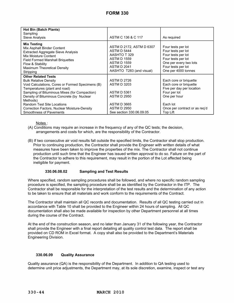
FORM 330
MARCH 2010
330-44
Hot Bin (Batch Plants) Sampling Sieve Analysis
ASTM C 136 & C 117
As required
Mix Testing Mix Asphalt Binder Content Extracted Aggregate Sieve Analysis Mix Moisture Content Field Formed Marshall Briquettes Flow & Stability Maximum Theoretical Density Stripping
ASTM D 2172, ASTM D 6307 ASTM D 5444 AASHTO T 329 ASTM D 1559 ASTM D 1559 ASTM D 2041 AASHTO T283 (and visual)
Four tests per lot Four tests per lot Four tests per lot Four tests per lot One per every two lots Four tests per lot One per 4000 tonnes
Other Related Tests Bulk Relative Density Void Calculations, Cores or Formed Specimens (B) Temperatures (plant and road) Sampling of Bituminous Mixes (for Compaction) Density of Bituminous Concrete (by Nuclear Methods) Random Test Site Locations Correction Factors, Nuclear Moisture-Density Smoothness of Pavements
ASTM D 2726 ASTM D 3203 ASTM D 5361 ASTM D 2950 ASTM D 3665 ASTM D 2950 See section 330.06.09.05
Each core or briquette Each core or briquette Five per day per location Four per lot One per hour Each lot Once per contract or as req’d Top Lift
Notes : (A) Conditions may require an increase in the frequency of any of the QC tests; the decision,
arrangements and costs for which, are the responsibility of the Contractor. (B) If two consecutive air void results fall outside the specified limits, the Contractor shall stop production.
Prior to continuing production, the Contractor shall provide the Engineer with written details of what measures have been taken to improve the properties of the mix. The Contractor shall not continue production until such time that the Engineer has issued written approval to do so. Failure on the part of the Contractor to adhere to this requirement, may result in the portion of the Lot affected being ineligible for payment.
330.06.08.02 Sampling and Test Results Where specified, random sampling procedures shall be followed, and where no specific random sampling procedure is specified, the sampling procedure shall be as identified by the Contractor in the ITP. The Contractor shall be responsible for the interpretation of the test results and the determination of any action to be taken to ensure that all materials and work conform to the requirements of the Contract. The Contractor shall maintain all QC records and documentation. Results of all QC testing carried out in accordance with Table 10 shall be provided to the Engineer within 24 hours of sampling. All QC documentation shall also be made available for inspection by other Department personnel at all times during the course of the Contract.
At the end of the construction season, and no later than January 31 of the following year, the Contractor shall provide the Engineer with a final report detailing all quality control test data. The report shall be provided on CD ROM in Excel format. A copy shall also be provided to the Department’s Materials Engineering Division. 330.06.09 Quality Assurance Quality assurance (QA) is the responsibility of the Department. In addition to QA testing used to determine unit price adjustments, the Department may, at its sole discretion, examine, inspect or test any

FORM 330
MARCH 2010
330-45
aspect of the Contractor’s work as deemed appropriate. Such inspections and testing shall not relieve the Contractor of his responsibilities for quality control. The Contractor shall supply a field laboratory for Quality Assurance purposes only as per Section 111 of the Department’s Specifications Book. The laboratory will be located and setup as approved by the Engineer at the nearest highway depot. The Contractor will make separate arrangements for QC testing. 330.06.09.01 Sampling All QA samples shall be taken and labeled by the Contractor in the presence of the Engineer (or designated representative). Random sample locations (loose samples and core samples) for QA testing shall be generated by the Engineer for each Lot and trial mix. Cores damaged during sampling or handling shall be discarded and new samples shall be taken immediately adjacent (within 0.3 meters) to the original sample location. For the trial mix, a minimum of 1 (one) random loose sample shall be taken for QA testing (i.e. for determination of maximum theoretical density). The Engineer will be responsible for transporting the samples to the Department representative’s laboratory. Neither loose nor core samples will be taken from small areas such as tapers, aprons, bridge approaches, areas of handwork, and asphalt mix used for isolated leveling and repair of failed areas, however, the tonnage contained therein will be included in the Lot. Random samples will not be taken in areas of obvious surface defects as indicated in 330.06.07 Surface Defects. These areas will be marked and repaired in accordance with 330.06.12.01 Removal and Replacement. The Engineer may use discretion in relocating random core locations that fall within areas of severe vertical curvature or grade (i.e. at the base or crest of a hill or >10% grade). 330.06.09.02 Asphalt Binder Content, Gradation and Air Voids Loose samples will be taken on the road behind the paver and retrieved prior to compaction per Section 330.06.02.05. The Engineer will provide the Contractor with approximately 30 minutes advance notice of loose sampling requirements, based on projected tonnage/production rates. Each sample will be split into 2 (two) equal portions. One portion will be tested and the other will be set aside in the event that a re-test is required. For asphalt binder content, the unit price adjustment will be applied to both the individual sample and the lot average as indicated in Table 12. Performance for gradation and air voids will be evaluated for unit price adjustment in accordance to Tables 13 and 14 utilizing the mean of deviations for the lot.
The following acceptance criteria shall apply for all mixes:
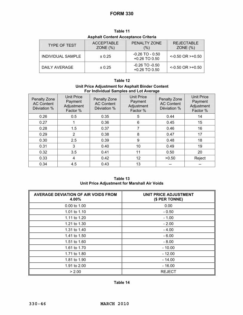
FORM 330
MARCH 2010
330-46
Table 11 Asphalt Content Acceptance Criteria
TYPE OF TEST ACCEPTABLE ZONE (%)
PENALTY ZONE (%)
REJECTABLE ZONE (%)
INDIVIDUAL SAMPLE ± 0.25 -0.26 TO - 0.50 +0.26 TO 0.50 <-0.50 OR >+0.50
DAILY AVERAGE ± 0.25 -0.26 TO -0.50 +0.26 TO 0.50 <-0.50 OR >+0.50
Table 12
Unit Price Adjustment for Asphalt Binder Content For Individual Samples and Lot Average
Penalty Zone AC Content Déviation %
Unit Price Payment
Adjustment Factor %
Penalty Zone AC Content Déviation %
Unit Price Payment
Adjustment Factor %
Penalty Zone AC Content Déviation %
Unit Price Payment
Adjustment Factor %
0.26 0.5 0.35 5 0.44 14 0.27 1 0.36 6 0.45 15 0.28 1.5 0.37 7 0.46 16 0.29 2 0.38 8 0.47 17 0.30 2.5 0.39 9 0.48 18 0.31 3 0.40 10 0.49 19 0.32 3.5 0.41 11 0.50 20 0.33 4 0.42 12 >0.50 Reject 0.34 4.5 0.43 13 -- --
Table 13 Unit Price Adjustment for Marshall Air Voids
AVERAGE DEVIATION OF AIR VOIDS FROM 4.00%
UNIT PRICE ADJUSTMENT
($ PER TONNE)
0.00 to 1.00
0.00 1.01 to 1.10
- 0.50
1.11 to 1.20
- 1.00 1.21 to 1.30
- 2.00
1.31 to 1.40
- 4.00 1.41 to 1.50
- 6.00
1.51 to 1.60
- 8.00 1.61 to 1.70
- 10.00
1.71 to 1.80
- 12.00 1.81 to 1.90
- 14.00
1.91 to 2.00
- 16.00 > 2.00
REJECT
Table 14
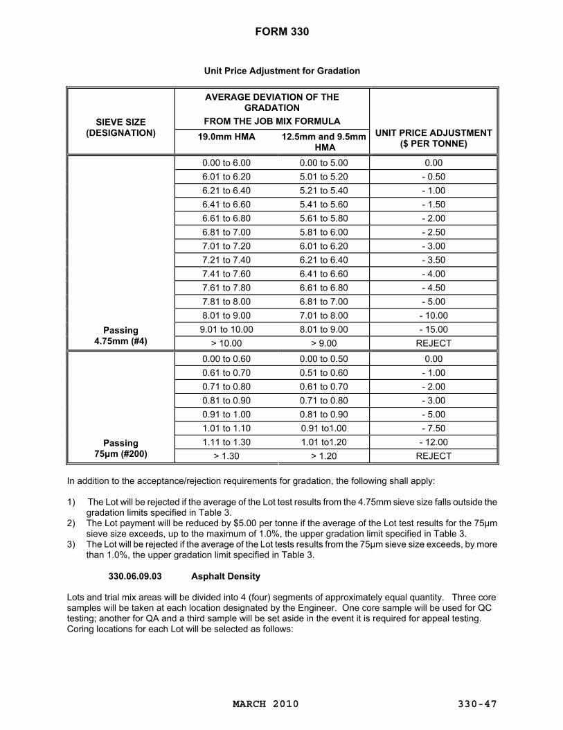
FORM 330
MARCH 2010
330-47
Unit Price Adjustment for Gradation
AVERAGE DEVIATION OF THE
GRADATION FROM THE JOB MIX FORMULA
SIEVE SIZE
(DESIGNATION)
19.0mm HMA
12.5mm and 9.5mm
HMA
UNIT PRICE ADJUSTMENT
($ PER TONNE)
0.00 to 6.00
0.00 to 5.00
0.00 6.01 to 6.20
5.01 to 5.20
- 0.50
6.21 to 6.40
5.21 to 5.40
- 1.00 6.41 to 6.60
5.41 to 5.60
- 1.50
6.61 to 6.80
5.61 to 5.80
- 2.00 6.81 to 7.00
5.81 to 6.00
- 2.50
7.01 to 7.20
6.01 to 6.20
- 3.00 7.21 to 7.40
6.21 to 6.40
- 3.50
7.41 to 7.60
6.41 to 6.60
- 4.00 7.61 to 7.80
6.61 to 6.80
- 4.50
7.81 to 8.00
6.81 to 7.00
- 5.00 8.01 to 9.00
7.01 to 8.00
- 10.00
9.01 to 10.00
8.01 to 9.00
- 15.00
Passing 4.75mm (#4)
> 10.00
> 9.00
REJECT
0.00 to 0.60
0.00 to 0.50
0.00
0.61 to 0.70
0.51 to 0.60
- 1.00 0.71 to 0.80
0.61 to 0.70
- 2.00
0.81 to 0.90
0.71 to 0.80
- 3.00 0.91 to 1.00
0.81 to 0.90
- 5.00
1.01 to 1.10
0.91 to1.00
- 7.50 1.11 to 1.30
1.01 to1.20
- 12.00 Passing
75μm (#200)
> 1.30
> 1.20
REJECT In addition to the acceptance/rejection requirements for gradation, the following shall apply: 1) The Lot will be rejected if the average of the Lot test results from the 4.75mm sieve size falls outside the
gradation limits specified in Table 3. 2) The Lot payment will be reduced by $5.00 per tonne if the average of the Lot test results for the 75μm
sieve size exceeds, up to the maximum of 1.0%, the upper gradation limit specified in Table 3. 3) The Lot will be rejected if the average of the Lot tests results from the 75μm sieve size exceeds, by more
than 1.0%, the upper gradation limit specified in Table 3. 330.06.09.03 Asphalt Density Lots and trial mix areas will be divided into 4 (four) segments of approximately equal quantity. Three core samples will be taken at each location designated by the Engineer. One core sample will be used for QC testing; another for QA and a third sample will be set aside in the event it is required for appeal testing. Coring locations for each Lot will be selected as follows:

FORM 330
MARCH 2010
330-48
The Engineer shall provide the Contractor with sample locations (station and offset) following placement of all asphalt concrete within a given Lot or trial mix area. Where traffic control conditions warrant, consideration shall be given to providing random core sample locations for a given mat (i.e. before all asphalt concrete for the Lot has been placed). Cores shall not be taken within 0.15 m of the pavement edge or longitudinal joint, nor closer than 6 m to a transverse joint. Cores shall not be taken within 10 m of a loose sample location. Cores shall be obtained in accordance with ASTM D5361 within a minimum of 12 hours and a maximum 24 hours after the placement of the asphalt concrete. The Contractor shall have the option of using dry ice to obtain the cores earlier than 12 hours after placement. The Engineer may use discretion in relocating random core locations that fall within areas of severe vertical curvature or grade (i.e. base or crest of a hill). The percent compaction for each core sample shall be determined using the individual core density and the average maximum theoretical density for the Lot. The sample mean of the Lot or trial mix density result will be evaluated for Acceptance and Rejection requirements as indicated in Table 15.
Table 15
Unit Price Adjustment for Density
% OF MAXIMUM THEORETICAL
DENSITY
UNIT PRICE
ADJUSTMENT ($ PER TONNE)
% OF MAXIMUM THEORETICAL
DENSITY
UNIT PRICE
ADJUSTMENT ($ PER TONNE)
% OF MAXIMUM THEORETICAL
DENSITY
UNIT PRICE
ADJUSTMENT ($ PER TONNE)
>98.5 REJECT 92.7 + 0.20 90.7 - 3.20 98.5 -5.00 92.6 + 0.10 90.6 - 3.60 98.4 -4.00 92.5 0.00 90.5 - 4.00 98.3 -3.00 92.4 - 0.10 90.4 - 4.40 98.2 -2.00 92.3 - 0.20 90.3 - 4.80 98.1 -1.00 92.2 - 0.30 90.2 - 5.20 98.0 -0.50 92.1 - 0.40 90.1 - 5.60 97.9 -0.40 92.0 - 0.50 90.0 - 6.00 97.8 -0.30 91.9 - 0.60 89.9 -7.00 97.7 -0.20 91.8 - 0.70 89.8 -8.00 97.6 -0.10 91.7 - 0.80 89.7 -9.00 97.5 0.00 91.6 - 0.90 89.6 -10.00 97.4 +0.10 91.5 - 1.00 89.5 -11.00 97.3 +0.20 91.4 - 1.20 89.4 -12.00 97.2 +0.30 91.3 - 1.40 89.3 -13.00 97.1 +0.40 91.2 - 1.60 89.2 -14.00
≤97.0 thru +0.50 91.1 - 1.80 89.1 -15.00 to ≥93.0 + 0.50 91.0 - 2.00 89.0 -16.00
92.9 + 0.40 90.9 - 2.40 <89.0 REJECT 92.8 + 0.30 90.8 - 2.80
330.06.09.04 Thickness (New Construction) The asphalt concrete shall be placed in lifts at the prescribed thickness as per the contract specifications and/or as directed by the Engineer. The pavement thickness shall be determined from the cores obtained in 330.06.09.03 Asphalt Density. Price adjustments for thickness will be applied to new construction only. The maximum thickness for a Lot shall be determined on a Lot by Lot basis. Individual thickness results will be evaluated for Acceptance and Rejection requirements as indicated in Table 16.

FORM 330
MARCH 2010
330-49
Table 16 Unit Price Adjustment for Thickness
For all hot mix asphalt types the penalty for thickness shall be as follows: Full payment for at least 3 out of 4 samples meeting the below tolerances Repair/Replace/Reject for 2 or more out of 4 samples failing to meet the below tolerances a) Thickness = specified application rate/bulk relative density obtained from core samples b) Lift thickness tolerance for base and surface course only Tolerance = 0.20 x specified thickness (base course) Tolerance = 0.15 x specified thickness (surface course) c) If the Thickness for the first lift of asphalt concrete is less than the tolerance, and a second lift of asphalt concrete is to be placed under the Contract, the Contractor shall place the second lift of the asphalt concrete to achieve a thickness equivalent to the total combined thickness required. The total first lift thickness shall be verified, for the deficient Lot, by the cores taken from the second lift of the identified deficient Lot.
330.06.09.04.01 Material Application Rate (Rehabilitated Pavements) On rehabilitated pavements, hot mix asphalt shall be applied to the roadway at the rate or rates specified in the Tender, or as specified by the Engineer. Material application rates will be determined by the tonnage delivered to the paver as recorded by weigh tickets generated by automated scales, divided by the area covered by the Lot after allowance has been made for entrances and/or intersections The Contractor shall provide the material application rates to the Engineer at the completion of each Lot. The pay adjustment for material application rate is shown in the following table. The acceptance limit is the limiting value of the actual material application rate, expressed as a percentage of the specified material application rate for the Lot, below which the Lot is rejected. If the application rate of a Lot is outside the acceptance limit, the Lot is rejected automatically regardless of the values of other acceptance parameters.
Table 17 Pay Adjustments for Material Application Rate
Actual Application Rate Expressed as % of Specified Application Rate
Unit Price Adjustment ($ per tonne)
Lower Lift or Single Lift Top Lift of Multiple Lifts ≥ 110 -$6.00 for all material in the Lot up to
110% and no payment for product in excess of 110.0%
106.0 – 109.9 -$6.00 for all material in the Lot up to 106% and no payment for product in excess of 106.0%
105.0 – 105.9
-$4.00 for all material in the Lot
-$4.00 for all material in the Lot 104.0 – 104.9 $0.00 -$2.00 for all material 96.0 – 103.9 +$0.50 +$0.50 94.0 – 95.9 -$1.00 -$1.00 92.0 – 93.9 -$2.00 -$2.00 90.0 – 91.9 -$3.00 -$3.00 85.0 – 89.9 -$5.00 -$5.00
< 84.9 Rejected, Mill and Fill and/or rejected with no remedial work required at the discretion of the Engineer
Rejected, Mill and Fill, Overlay and/or rejected with no remedial work required at the discretion of the Engineer

FORM 330
MARCH 2010
330-50
330.06.09.05 Pavement Smoothness The smoothness of the finished surface of the top lift of the pavement structure shall be determined by using a profilograph after final rolling of the surface to be tested. Normally, the outer wheel paths of all lanes will be tested, in 100 m sections, or lots. Other wheel paths may also be tested in addition to, or as a substitution for, the outer wheel path, as directed by the Engineer. The profile measurements will normally be taken using a California Profilograph device, which profiles the pavement along a wheel path in accordance with ASTM E-1274, Standard Test Method for Measuring Pavement Roughness Using a Profilograph. The resulting measurements will be compiled to produce a Profile Index (PI). This determination of smoothness will be made by the Department, or its representative. The Profile Index (PI) for each lane is the cumulative profile reading of the outer wheel path in millimeters per 100 m section, in excess of the 5 mm blanking band. 330.06.09.05.01 Profile Index Limits The surface of the profiled pavement shall conform to the following Smoothness requirements:
Table 18
Smoothness Requirements
Roadway Alignment Section Profile Index (mm / 100 m)
RLU-80 CLASSIFICATION AND ABOVE
12 mm OR LESS INTERCHANGE RAMPS, TAPERS*, AND HIGHWAYS OF LOWER CLASSIFICATION THAN RLU-80
N/A
If the Smoothness requirements are not met, the Contractor shall repair the sections, or pay a price adjustment based on the Profile Index. These price adjustments will be applied based on the square meters of the final pavement surface as outlined in Table 19. For price adjustment purposes, the width of the final pavement surface includes the driving lane and adjacent shoulders.
Table 19
Profile Index Price Adjustment Schedule
PROFILE INDEX PI ( mm / 100m)
PRICE ADJUSTMENT $ PER
SQUARE METER
PROFILE INDEX PI (
mm / 100m)
PRICE ADJUSTMENT $ PER
SQUARE METER
< 4.0
$0.338
18.1 to 21.0
-$0.540 4.1 to 5.5 incl.
$0.270
21.1 to 22.5
-$0.810
5.6 to 7.0
$0.203
22.6 to 24.0
-$1.080 7.1 to 8.5
$0.135
24.1 to 25.5
-$1.350
8.6 to 10.0
$0.068
25.6 to 27.0
-$1.620 10.1 to 15.0
$0.00
27.1 to 28.5
-$1.890
15.1 to 18.0
-$0.270
28.6 to 30.0
-$2.160 EACH ADDITIONAL 1.5mm INCREMENT ABOVE 30.0
-(NO OF INCREMENTS X $0.54 +$2.160)

FORM 330
MARCH 2010
330-51
330.06.09.05.02 Surface Deviations (Individual Bumps and Dips)
Individual bumps and dips shall not exceed 8 mm in 7.6 m in the vertical direction as measured by the Profilograph. Where individual bumps and dips exceed 8 mm in 7.6 m, they may be corrected or the Contractor may elect to accept a penalty as per Table 20. The 5 mm blanking band is not applied to the bump and dip measurements. Not withstanding, transverse joints are still subject to Section 330.06.05.05.01 and any irregularity should be immediately corrected.
Table 20 Bump and Dip Penalties
Bumps / Dips Measured in the
Vertical Direction
Penalty
Bumps / Dips Measured in the
Vertical Direction
Penalty 8.1 - 9 mm
$ 200
13.1 - 14 mm
$ 1200
9.1 - 10 mm
$ 400
14.1 - 15 mm
$ 1400 10.1 - 11 mm
$ 600
15.1 - 16 mm
$ 1600
11.1 - 12 mm
$ 800
16.1 - 17 mm
$ 1800 12.1 - 13 mm
$ 1000
17.1 - 18 mm
$ 2000
Each Additional 1 mm Increment Above 18 mm
(No. of Increments x $ 500) + $ 2000
330.06.09.06 Reporting The Engineer will provide the Contractor with a copy of the results of QA testing within 1 (one) working day of their availability. Acceptance test results for a given Lot will not be reported to the Contractor until the quality control results for that Lot have been reported to the Engineer. Tests performed by the Engineer will not be considered to be quality control tests. If the Lot results for any one of the QA properties are outside the acceptance limits as listed in Tables 11 to 17, the Lot will be evaluated in accordance with 330.06.11 Analysis of Rejected Lots. 330.06.10 Appeals The Contractor may appeal the results of QA testing for density, asphalt binder content, gradation and thickness for any rejected or penalized Lot. The Contractor may appeal the results of QA testing for density and thickness for any rejected or penalized trial mix. In the event of an appeal, the Contractor shall serve notice of appeal to the Engineer, in writing, within 48 hours of receipt of the QA test results. The Contractor may have a representative present during appeal testing. During the period of the testing, the Contractor’s representative shall comment on anything concerning the testing which he or she does not consider to be valid and the Engineer shall respond to all comments in order to resolve them. Prior to leaving the testing laboratory any unresolved comments regarding the testing procedures are to be given to the Engineer in writing. Any comments, with respect to the testing procedures, which are made subsequent to the Contractor’s representative leaving the laboratory, will not be considered. The new Sample Result, Mean or Mean of the Deviations, whichever the case may be, so obtained shall be binding on both the Contractor and the Department. 330.06.10.01 Appeal of Individual Test Results The Contractor may appeal individual results of acceptance testing for the asphalt binder content and gradation properties only. When an individual test result from a Lot is challenged, the validity of the test result in question will be determined in accordance with ASTM E 178, Standard Practice for Dealing with Outlying Observations, using a “t”-test at a 5 (five) percent significance level. If the outlier test procedure shows that the challenged test result is valid, then it will be used in the calculations. If the outlier test procedure shows that the challenged test result is not valid, then the test result will be discarded unless there is an obvious error in the calculations or in transposing of the numbers. If there is no obvious error,
FORM 330
MARCH 2010
330-52
the referee sample will be tested by the Engineer. Regardless of the presence of outlying observations in the re-tested sample and remaining original results, the results from the referee sample will be binding on both the Contractor and the Department and will be used in the calculations. The results from the outlier testing will be used for any subsequent appeals. The referee sample shall be tested for the following mix properties: asphalt binder content, gradation, and maximum density, in the event that the results are needed for additional appeals, if required. A new Mean or Mean of the Deviations, for the combined test results, will be determined and this value will be used for acceptance and unit price adjustments.
330.06.10.02 Appeal of Test Results for the Entire Lot The Contractor may appeal the entire Lot QA test results for the density, binder content, gradation and thickness properties for any rejected or penalized Lot only once. Appeal of test results for the entire Lot will only be considered if just cause can be shown by the Contractor that the acceptance test results are not representative of the product placed. If the Contractor’s quality control test results indicate greater deviations from the JMF than the quality assurance test results, no appeal will be allowed. 330.06.10.02.01 Appeal of Lot Binder Content and Gradation If the individual sample or Lot asphalt binder content and/or Lot gradation, and/or air voids are appealed, the Engineer will submit the referee samples obtained in 330.06.09.02 Asphalt Binder Content, Gradation and Air Voids for testing at the Department representative’s laboratory. All original test results of the property appealed will not be considered. Only the new test results from the appeal will be used.
330.06.10.02.02 Appeal of Lot or Trial Mix Density If the Lot or Trial Mix density is appealed, the Engineer will submit the appeal core samples obtained in 330.06.09.03 Asphalt Density. Only the new test results from the appeal will be used.
330.06.10.02.03 Appeal of Lot or Trial Mix Thickness If the Lot or Trial Mix thickness is appealed, the Contractor will take 7 (seven) more cores at random locations as determined by the Engineer. These cores shall be tested at the Department representative’s laboratory. The high and low test results from the original Lot will be discarded and the remaining test results will be combined with the test results for the new samples. For thickness appeals, 7 (seven) of the 9 (nine) test results must meet or exceed the lift thickness tolerance specified in Table 16. 330.06.10.02.04 Payment of Appeal Testing Costs If the new test results after the appeal process indicate that a penalty no longer applies, then the testing costs incurred by the Department during the appeal process for that Lot shall be borne by the Department. The Contractor shall be responsible for any other costs that they may incur. If the new test results after the appeal process verify that a unit price adjustment or rejection remains valid for that Lot, the sampling and testing costs incurred by the Department during the appeal procedure shall be charged to the Contractor. 330.06.11 Analysis of Rejected Lots Following an appeal of the entire Lot, in accordance with 330.06.10.02 Appeal of Test Results for the Entire Lot, if the new test results continue to indicate rejection, the new test results will be analyzed, at the discretion of the Engineer, to determine whether or not a portion of the Lot is acceptable. An analysis, as determined by the Engineer, will be carried out to determine which segments may be acceptable. If the analysis indicates partial Lot acceptance, only those areas corresponding to the sample segment(s) in which rejected material placement occurred shall be subject to 330.06.12.01 Removal and Replacement.

FORM 330
MARCH 2010
330-53
Any and all price adjustments corresponding to the recalculated test results (excluding those in the rejected segment(s)) shall apply.
330.06.12 Repairs Rejected work shall be repaired, remedied, overlaid, or removed and replaced at the Contractor’s expense. The asphalt concrete replacement or overlay shall be the same asphalt concrete mix designation as that which is removed or overlaid. All joints and the underlying asphalt concrete mat shall be tack-coated prior to repair. The mix tonnage associated with the repair shall be produced in accordance with this specification. The repair tonnage shall be sampled in accordance with 330.06.02.05 Lot. Asphalt concrete comprising repaired areas shall be subject to testing in accordance with 330.06.08 (Quality Control) and 330.06.09 (Quality Assurance.) Unit price adjustments calculated in accordance with Tables 12 to 17 and price adjustments from Tables 19 and 20.
The cost of retesting shall be borne by the Contractor. All costs associated with repairs, removal and replacement, or overlays are the responsibility of the Contractor. 330.06.12.01 Removal and Replacement Rejected Lots or segments of Lots shall be removed by cold milling the full width of the affected mat and full depth of the lift in which the work is being performed. Material removed shall become the property of the Contractor, to haul and stockpile or otherwise dispose of in an environmentally acceptable manner, at the Contractor’s expense.
330.06.12.02 Overlaying Overlaying as a method of repair will only be considered in areas designated by the Engineer, for Lots or segments of Lots which are subject to rejection based on thickness or smoothness. The asphalt concrete mix used to construct the overlay shall meet the same requirements as the pavement which is overlaid. The overlay shall extend the full width of the underlying pavement surface and have a finished compacted thickness of not less than 40 mm. A keyed joint shall be constructed at each end of the overlaid section as per 330.06.05.05.05 Keyed Joints. If an acceptable grade and cross slope cannot be achieved, the Contractor shall repair the area in accordance with 330.06.12.01 Removal and Replacement. If an overlay results in the need for additional shouldering material or adjustments to guide posts and guardrail, this work shall be carried out, at the Contractor’s expense, in accordance with the applicable items as per the Standard Specification. 330.06.13 Measurement for Payment 330.06.13.01 Measurement for Payment for Asphaltic Surface Course, Asphaltic Base
Course, Asphaltic Levelling Course Type I and II The quantity of asphalt concrete to be measured for payment shall be the number of tonnes of mix placed and accepted in accordance with this specification. Unit price adjustments calculated in accordance with Tables 12 to 17 shall apply. 330.06.13.02 Measurement for Payment for Asphalt Cement The asphalt cement will be measured in tonnes, rounded to two decimal places. Payment for Asphalt Cement shall be as per the percentage (%) of asphalt cement required in the approved Job Mix Formula. However, where Asphalt Cement contents are found to be deficient to the point of being in the penalty zones

FORM 330
MARCH 2010
330-54
subsequently described, Asphalt Cement will be paid on actual content only, as determined by ASTM D6307 Standard Test Method for Asphalt Content of Hot-Mix Asphalt by the Ignition Method. Any moisture content in the hot mix asphalt will be determined and deducted. The method of determination of this moisture content will be in accordance with AASHTO 329 Standard Method of Test for Moisture Content of Hot Mix Asphalt by Oven Method. Samples of hot mix asphalt shall be taken randomly, in accordance with 330.06.09.02 and tested to ensure conformance with the specifications stated herein. Sampling and testing shall be performed in accordance with ASTM D979 and ASTM D6307, Method A. Additional samples may also be taken and tested in accordance with ASTM D2172, Method E for verification purposes. If the test results representing the individual sample or the Lot average for asphalt cement content falls into the above-stated “Penalty Zone”, the payments for both Asphalt Cement and Hot Mix Asphalt shall be adjusted by deducting a percentage from the unit prices per Table 12 for the Individual Sample or for the Lot, or both as appropriate. These adjustments shall apply to the areas of pavement represented by these samples. If the test results representing the individual sample or the Lot average fall into the above-stated “Rejectable Zone”, then no payment will be made for either the asphalt cement or hot mix asphalt represented by those samples. In the event of any and all disputes over asphalt content, the asphalt contents as determined by the Engineer, in accordance with the above stated method, shall govern in all cases.
330.06.14 Basis of Payment 330.06.14.01 Basis of Payment for Asphaltic Surface, Asphaltic Base Course, Asphaltic
Leveling Courses Type I and II, and Patching Asphalt concrete will be paid for at the contract unit price per tonne for mix incorporated and accepted in the work, which price shall be full compensation for furnishing and transporting of all materials including aggregates, natural sand, PGAB, heating, handling, mixing, placing and compacting the mix, the supply of all equipment, plant, labour, traffic control and incidentals necessary to complete the work.
All price adjustments determined in accordance with this specification will be calculated and issued on the final progress estimate.
330.06.14.02 Basis of Payment for Asphalt Cement Payment at the contract price for Asphalt Cement shall be compensation in full for all labor, materials, and equipment to supply the Asphalt Cement cost shall include purchase, loading, transportation, unloading and storage at the asphalt plant.
330.06.14.03 Basis of Payment for Rejected Mix
The Department will pay for only the original mix quantity. The Contractor is fully responsible to bear all costs associated with repair of rejected areas, including all materials, equipment, plant, labour, traffic control and incidentals necessary to complete the work to the satisfaction of Engineer. If the Department determines the rejected material may remain in the work, and the Contractor elects not to repair the affected area, payment for the rejected mix components will be at 50% of the various contract unit prices.

FORM 403
403-1MARCH 2010
GOVERNMENT OF NEWFOUNDLAND AND LABRADORDepartment of Transportation and WorksHighway Design Division
SECTION 403EXCAVATION FOR FOUNDATIONS
INDEX403.01 SCOPE403.02 ENVIRONMENTAL REQUIREMENTS403.03 EXCAVATION FOR FOUNDATION
403.03.01 Excavation for Foundation for Culverts Installed in All Places Other than Across Existing Roads403.03.02 Excavation for Foundation for Culverts Installed Across an Existing Road in a Low Fill403.03.03 Excavation for Foundation for Culverts Installed Across an Existing Road in a High Fill403.03.04 Excavation for Foundation for Gabions403.03.05 Excavation for Foundation for Footings403.03.06 Excavation for Foundation for Bin-Type Retaining Wall403.03.07 Excavation for Foundation for Welded Wire Retaining Wall403.03.08 Backfill Material
403.04 CLASSIFICATION403.05 MEASUREMENT FOR PAYMENT
403.05.01 Measurement for Payment for Excavation for Foundation for Culverts Installed in All Places Other than AcrossExisting Roads
403.05.02 Measurement for Payment for Excavation for Foundation for Culverts Installed Across an Existing Road in a Low Fill403.05.03 Measurement for Payment for Excavation for Foundation for Culverts Installed Across an Existing Road in a High Fill403.05.04 Measurement for Payment for Excavation for Foundation for Items Other than Culverts
403.06 BASIS OF PAYMENT
403.01 SCOPE
This work shall include labour, equipment and materials required to carry out excavation such as that required to obtain a foundation forsuch structures as bin-wall, culverts, footings, and gabions, and shall include hauling up to 1 km, handling and incorporation of all suitablematerials into fill construction in accordance with Section 204 "Grading of Fill", and shall include the hauling up to 1 km, and handling of theunsuitable materials and the trimming of such unsuitable materials along embankment slopes or elsewhere, all as directed by the Engineer.
The work shall also include excavation required prior to disposal or salvage of culvert or pipe.
The work shall not include the excavation of those materials which the Contractor had previously placed, of his own choice as a temporarymeasure, and is required to excavate to facilitate the placing of, for example, select granulars. Any such excavation of materials whichwere placed as a temporary measure by choice of the Contractor, shall be at the Contractor's expense.
Where the quantity of excavation exceeds that required in the backfilling operation or to construct the fills as directed by theEngineer, the surplus shall be used to widen the fills or otherwise disposed of as directed by the Engineer.
403.02 ENVIRONMENTAL REQUIREMENTS
The Contractor shall be aware of Division 8. Where unwatering is required, it shall be carried out as specified in Section 180.
FORM 403
403-2 MARCH 2010
403.03 EXCAVATION FOR FOUNDATION
The Contractor shall excavate along the lines, to the width and to the grade required by the Engineer.
403.03.01 Excavation for Foundation for Culverts Installed in All Places Other than Across Existing Roads
In the particular case of excavation for foundation for culverts installed in all places except across existing roads, the Contractor willnormally be required to excavate for a width equal to the nominal diameter of the pipe, or the nominal span of the arch in the case of pipearches, plus a distance of 300 mm on each side of the culvert, unless required otherwise by the Engineer. The depth of the excavationshall be as shown on Form 1236 "Typical Culvert Bedding and Backfill Details", Form 1231 "Typical Structural Plate Round Pipe Beddingand Backfill Details", or Form 1232 "Typical Structural Plate Pipe Arch Bedding and Backfill Details", as appropriate, or as directed by theEngineer.
Excavation in addition to that required by the Engineer, will be considered incidental to the works.
403.03.02 Excavation for Foundation for Culverts Installed Across an Existing Road in a Low Fill
In the particular case of excavation for foundation for culverts installed across an existing road where the excavation is 1.25 m deep, orless, the Contractor will be required to excavate for a width equal to the nominal diameter of the pipe, plus 0.3 m on each side.
The depth of excavation shall be as shown on Form 1236 "Typical Culvert Bedding and Backfill Details", or as directed by the Engineer.
Excavation in addition to that required by the Engineer, will be considered incidental to the works.
403.03.03 Excavation for Foundation for Culverts Installed Across an Existing Road in a High Fill
In the particular case of excavation for foundation for culverts installed across an existing road where the excavation is deeper than 1.25 m,the Contractor will be required to excavate for a width at the bottom of the trench, equal to the nominal diameter of the pipe, plus 0.3 m oneach side. However, at the top of the trench, the width shall be equal to the bottom width plus two times the depth of the trench.
For culverts where the depth of excavation is greater than 5.0m, calculated nominal excavation volumes will include the provision of abench of nominal width 4.0m. The bench is intended to assist in the operation of removing the old culvert and installing the new one. Thelocation of the bench will be such that their will be 5.0m from the bottom of the culvert to the bench or as determined in the field by theengineer.
The depth of excavation shall be as shown on Form 1236 "Typical Culvert Bedding and Backfill Details", Form 1231 "Typical StructuralPlate Round Pipe Bedding and Backfill Details", or Form 1232 "Typical Structural Plate Pipe Arch Bedding and Backfill Details", or Form1226 “Benching Detail” as appropriate, or as directed by the Engineer.
Excavation in addition to that required by the Engineer, will be considered incidental to the works.
403.03.04 Excavation for Foundation for Gabions
In the case of excavation for foundations for gabions, the Contractor will normally be required to excavate an area slightly larger than thenominal base area, to a depth as required by the Engineer.
403.03.05 Excavation for Foundation for Footings
In the case of excavation for concrete footings for structural plate arches, the excavation pay lines shall be the length of the footing plus300 mm on each end times the width of the footing plus 300 mm on each side times the depth between original ground line and foundationelevation or as directed by the Engineer. All excavation in addition to the above will be considered incidental to the works.
When a footing is to rest on an excavated surface other than rock, special care shall be taken not to disturb the bottom of the excavation. In soft or wet conditions, the final removal of material to foundation level shall not be made until the Contractor is ready to proceed with theconstruction of the footing.
When material at the founding elevation is Other Material and has been over excavated, the elevation shall be re-established by replacingwith suitable material and compacting it to the bearing capacity of the original material as approved by the Engineer. When the foundingmaterial is Solid Rock and has been over excavated, the foundation elevation shall be re-established to the original elevation with massconcrete. First, all loose and compressible material shall be removed from the excavation to the satisfaction of the Engineer. Next,

FORM 403
403-3MARCH 2010
concrete shall be placed to the foundation elevation and shall fill the entire volume of the over excavation. Concrete shall be of a qualitycompatible with that used in the footing. No compensation will be provided for the cost of remedial measures required by the Engineer as aresult of over excavation by the Contractor.
403.03.06 Excavation for Foundation for Bin-Type Retaining Wall
In the case of excavation for bin-type retaining wall, the excavation lines shall be the length of the structure plus one metre on each endtimes the width of the structure plus one metre on each side times the actual depth from original ground to the base elevation or 200 mmbelow the base elevation where an unyielding or rock foundation exists. When the foundation is soft or has non-uniform bearing capacity,the lines for the excavation shall be as directed by the Engineer.
All excavation in addition to the above will be considered incidental to the works.
403.03.07 Excavation for Foundation for Welded Wire Retaining Wall
In the case of excavation for welded wire retaining wall, the excavation lines shall be the length of the structure plus 0.3 m on each endtimes the width of the structure plus 0.3 m on each side times the actual depth from original ground to the base elevation or 200 mm belowthe base elevation where an unyielding or rock foundation exists. When the foundation is soft or has non-uniform bearing capacity, thelines for the excavation shall be as directed by the Engineer.
All excavation in addition to the above will be considered incidental to the works.
403.03.08 Backfill Material
Materials excavated as excavation for foundations will be used for backfill if the material is deemed suitable by the Engineer.
If there should be insufficient backfill material available from the excavations, then the Engineer will direct that material from a cut or from aborrow area will be used to complete the backfilling.
Frozen materials shall not be acceptable as backfill material.
403.04 CLASSIFICATION
Excavated materials will be classified as either "Solid Rock" or "Other Material" in accordance with Section 205 "Classification of ExcavatedMaterials".
403.05 MEASUREMENT FOR PAYMENT
Volumes of all classes of excavation described in 403.04 "Classification" will be measured in excavation and computed in cubic metresrounded to the nearest whole number.
During excavation operations whenever the character of material changes from one type to another, as classified in Section 205, then theContractor shall strip the area, within the limits, of all overlying material, and notify the Engineer in order that proper measurements or crosssections may be made. No allowance will be made for material excavated before such measurements or cross sections have been made.
For boulders present in Other Material; the three maximum rectilinear dimensions of boulders, actually excavated, will be measured andthe volume of each so determined. Volumes of the boulders which are equal to, or greater than, zero decimal five cubic metres will beincluded for payment as Excavation for Foundation Solid Rock.
Where excavation for foundation is carried out during existing pipe removal operations, the cross-sectional area of the pipe to be removedshall be determined, and deducted for excavation end areas used in volume of excavation determinations.
403.05.01 Measurement for Payment for Excavation for Foundation for Culverts Installed in All Places Other than AcrossExisting Roads
Measurement for payment for Excavation for Foundation for culverts installed in all places other than across existing roads shall be bymeans of the nominal volume of excavation.

FORM 403
403-4 MARCH 2010
Nominal volume of excavation shall be computed by an adaption of the Average End Area method of volume computation, in which endareas are calculated as the product of the required depth of excavation, times the nominal width of excavation.
The nominal width of excavation shall be taken as either: 1.0 m, or the nominal diameter of the culvert plus 0.6 m, whichever is greater.
403.05.02 Measurement for Payment for Excavation for Foundation for Culverts Installed Across an Existing Road in a Low Fill
Measurement for payment for Excavation for Foundation for culverts installed across an existing road where the excavation is 1.25 m deep,or less, shall be by means of the nominal volume of excavation.
Nominal volume of excavation shall be computed by an adaption of the Average End Area method of volume computation, in which endareas are calculated as the product of the required depth of excavation, times the nominal width of excavation.
The nominal width of excavation shall be taken as either: 1.0 m, or the nominal diameter of the culvert plus 0.6 m, whichever is greater.
403.05.03 Measurement for Payment for Excavation for Foundation for Culverts Installed Across an Existing Road in a HighFill
Measurement for payment for Excavation for Foundation for culverts installed across an existing road where the excavation is 1.25 m deep,or less, shall be by means of the nominal volume of excavation.
Nominal volume of excavation shall be computed by an adaption of the Average End Area method of volume computation, in which the endareas used in the calculations are nominal end areas. For each culvert, the volume shall be calculated using the excavation nominal endarea: at the inlet, at the edge of the road shoulder, at the road center line, at the edge of the other shoulder, and at the outlet. Theseindividual nominal end areas shall each be calculated in accordance with the typical cross section shown on Form 1226, “Typical CulvertExcavation Pay Limit Cross Section for Fills Deeper than 5.0m”.
403.05.04 Measurement for Payment for Excavation for Foundation for Items Other than Culverts
Measurements shall be of the actual amount of material moved from within the limits required by the Engineer.
The quantity to be measured shall be the number of cubic metres of excavated material as shown between the position of the ground linesas cross sectioned after grubbing operations have been completed (or when excavation for foundation is to be carried out in a cut, aftergrading of cut or excavation of muskeg or bog operations have been completed as the case may be), and the completed and acceptedexcavation lines. Material excavated outside of the required limits will not be included in measurement for payment. The volume of theexcavation to be computed by the average end area method of computation or as wedges or pyramids, as the case may be, whenterminating at grade points.
403.06 BASIS OF PAYMENT
Payment shall be at the Contract Unit Price per cubic metre for Excavation For Foundation, Solid Rock or Other Material, as the case maybe, hauled 1 km or under and the backfilling of the same in accordance with the plans or as directed by the Engineer. Such payment shallbe full compensation for all work herein described together with the labour, materials, and equipment-use required for excavating, handling,hauling up to 1 km, placing, and compacting in a fill as described in Section 204 "Grading of Fill" or stockpiling and reuse of the materialsexcavated as excavation for foundations for backfill of the excavation if the material is deemed suitable by the Engineer or disposing overslopes or otherwise directed by the Engineer.
Where the Engineer requires that Excavation for Foundation material be hauled in excess of 1 km, additional payment for overhaul will bemade in accordance with Section 215 "Overhaul on Excavation".
FORM 426
426-1JANUARY 2010
GOVERNMENT OF NEWFOUNDLAND AND LABRADORDepartment of Transportation and WorksHighway Design Division
SECTION 426DESIGN, SUPPLY AND INSTALLATION OF LONG SPAN STRUCTURAL PLATE ARCH
INDEX426.01 SCOPE426.02 DESIGN426.03 ENVIRONMENTAL PERMITS AND AUTHORIZATIONS426.04 MATERIALS426.05 ASSEMBLY AND BACKFILLING426.06 PROTECTION FROM TRAFFIC426.07 MEASUREMENT FOR PAYMENT426.08 BASIS FOR PAYMENT
426.01 SCOPE
This specification covers the requirements for the design, supply, and installation for a structural plate long span arch, box culvert or other typeof large metal pipe structure. The provision of footings for the arch is covered under Section 450 "Concrete Footings for Structural PlateArches". Should headwalls be required, then they may be covered separately under another item and specification. The provision of backfillfor the arch is covered under Section 411 "Select Backfill for Long Span Structural Plate Structures". The design life for the structural plate longspan arch/pipe must be a minimum of 75 years.
426.02 DESIGN
The Contractor shall be responsible for the design of the long span structural plate arch. The long span structure shall be of the stated length,span and rise, although minor variations from the stated span and rise will be considered.
The design shall be carried out in accordance with generally accepted standards of practice to meet CL-625 loading requirements, inaccordance with the Canadian Highway Bridge Design Code.
The design shall be prepared by a Professional Engineer who shall submit shop drawings and installation procedures to the Department at leasttwo weeks prior to start of construction. Shop drawings shall bear the stamp and signature of a Professional Engineer licensed to practice inthe Province of Newfoundland and Labrador.
The shop drawings shall specify the intended plate corrugation profile, together with the plate thickness. The design calculations for platethickness shall be included with the shop drawings.
Where the structure is intended as an underpass, provision shall be made to prevent water from the fill seeping through joins in the plates, andthen leaking on to the road below. This may be accomplished by designing the plate overlap so that the water sheds to the fill side of thestructure, rather than seeping through the joints.
Alternatively, such other means to prevent water seepage that are acceptable to the Engineer may be used.
426.03 ENVIRONMENTAL PERMITS AND AUTHORIZATIONS
Authorization from the Fish Habitat Management Branch, Fisheries and Oceans Canada's required for work in or near any watercourse or waterbody deemed to be viable fish habitat.
Where unwatering is required, the Contractor shall carry out this work in accordance with Section 180 "Unwatering Incidental to Work”.
The Contractor shall be aware of the requirements of Division 8.
426.04 MATERIALS

FORM 426
426-2 JANUARY 2010
The long span structural plate arch shall be of the length, span, rise, corrugation profile and plate thickness, as approved by the Department.
The Contractor will supply the plates, unbalanced channel, nuts, bolts, washers, ribs if required, and all necessary hardware including the boltsnecessary to fasten the structural plate arch to the unbalanced channel. All materials shall be of galvanized steel and conform to CSA StandardCAN3-G401-M81, or latest edition thereof.
426.05 ASSEMBLY AND BACKFILLING
The Contractor shall allow the concrete footings to cure for at least three days before commencing the assembly of the structural plate and thebolting of the plates to the channel embedded in the footing.
The cutting of plates or the drilling of holes in new structural plate arch construction will not be permitted. Any defective plates must be reportedto the supplier and corrective action taken by the supplier or manufacturer.
The Contractor shall assemble and install the structure in accordance with the designer's drawings, using procedures specified by the industryrepresentative and in accordance with the instructions of the Engineer. Prior to starting the work, the Contractor shall provide a copy ofassembly and installation drawings and procedures to the Engineer on site.
Backfilling shall not commence until footings and any concrete headwalls and wingwalls have cured to at least 70% of the specified designstrength at 28 days or cured for seven days, whichever comes first. This requirement may be increased by the Professional Engineer whostamps the design drawings.
Assembly and installation of the culvert shall be monitored by a qualified representative of the steel culvert industry, hereafter referred to asthe industry representative. The industry representative will be responsible for approval of backfill materials; approval of procedures for placingand compacting backfill materials; supervising culvert assembly and installation; and generally ensuring that the culvert is installed in accordancewith the requirements of the culvert designer and the culvert manufacturer. If the structure is intended to be an underpass, then the Contractorshall install such provisions as are required to make the structure watertight.
The industry representative shall monitor the Contractor's operations on a full time basis during backfill operations. The Department will carryout compaction tests on the backfill material under the direction of the industry representative.
Backfill material shall be carefully placed and compacted so that the correct shape of the structure is maintained. Deflections from the specifieddimensions shall be within the tolerances permitted by the culvert designer.
426.06 PROTECTION FROM TRAFFIC
Prior to allowing the movement of construction equipment or any vehicular traffic over the arch the depth of cover over the arch shall not beless than the manufacturer's recommended minimum cover for the particular loading condition.
426.07 MEASUREMENT FOR PAYMENT
Measurement for payment for the long span structural plate arch shall be the actual length of the installed plate arch, measured along the bottomof one side. The measurement shall be computed in metres, rounded to one decimal place.
426.08 BASIS OF PAYMENT
Payment at the contract price for the design, supply, and installation of the long span structural plate arch shall be compensation in full for allmaterials, labour, and use of equipment to: design, supply, transport, assemble, and install the plate arch, provide any required unwatering,and place and compact the backfill, together with the provision of supervision by a qualified representative from the long span structural platestructure industry.
Included in the materials which shall be supplied by the Contractor are all plates, unbalanced channels, nuts, bolts, and washers, together withany thrust beams, distribution slabs, ribs and gaskets, select backfill and such other items which may be included in the design.
FORM 450
450-1MARCH 2010
GOVERNMENT OF NEWFOUNDLAND AND LABRADORDepartment of Transportation and WorksHighway Design Division
SECTION 450CONCRETE FOOTINGS FOR STRUCTURAL PLATE ARCHES
INDEX450.01 SCOPE450.02 MATERIALS
450.02.01 Galvanized Channel450.02.02 Concrete450.02.03 Joints450.02.04 Reinforcing Steel
450.03 EXCAVATION450.04 FORMWORK450.05 PLACING OF REINFORCING STEEL450.06 PLACING CONCRETE AND CHANNEL450.07 JOINTS450.08 CURING THE CONCRETE450.09 TRIMMING450.10 MEASUREMENT FOR PAYMENT450.11 BASIS OF PAYMENT
450.01 SCOPE
This specification covers the Department's requirement for the construction of concrete footings for structural plate arches, and long spanstructural plate arches. The footings incorporating a galvanized channel, reinforcing steel, and dowels if required, shall be as shown on thedrawings, or as directed by the Engineer.
Dowels where required, shall be a separate contract item.
450.02 MATERIALS
450.02.01 Galvanized Channel
The Contractor will supply the galvanized channel sections. Galvanized channel is supplied and paid for under Section 424 of the SpecificationsBook, "Supply and Installation of Structural Plate Arch".
450.02.02 Concrete
Concrete for use in constructing the footings shall be supplied by the Contractor and shall conform to the following specific requirements:
CLASS OF CONCRETE 35 MPa at 28 DAYS
AGGREGATE MAXIMUM SIZE 20mm
AIR CONTENT 6% ± 1%
SLUMP 60mm ± 20mm
All concrete shall conform with Section 904 "Concrete Structures".
450.02.03 Joints
FORM 450
450-2 MARCH 2010
Joint materials shall be supplied by the Contractor. Material for forming isolation joints shall be 12 mm thick bituminous fibre material.
Material for forming control joints shall be 12 mm thick bituminous fibre material for the set-in-place type, or a bituminous filler material for thesaw-cut type.
450.02.04 Reinforcing Steel
Reinforcing steel shall be of the sizes shown in the drawings.
Reinforcing steel shall conform with the requirements of Section 905 "Concrete Reinforcement".
450.03 EXCAVATION
The Contractor shall excavate a foundation within the limits and to the grades as staked by the Engineer.
The excavation shall be carried out and paid for in accordance with Section 403 "Excavation For Foundations".
450.04 FORMWORK
Before placing formwork, the Contractor shall have drilled the required holes removed any dirt and debris that may be in the holes withcompressed air or other acceptable means, inserted the required dowels, free of oil, grease, excessive rust and scale, and grouted themsecurely in place where the contract documents indicate that dowels are required. Holes to be drilled into the rock for the insertion of dowelsshall have a maximum size of 1½-2 times the dowel diameter.
Formwork shall be supplied by the Contractor, and shall conform to the requirements of Section 907 "Formwork and Falsework".
450.05 PLACING OF REINFORCING STEEL
Reinforcing steel shall be placed in accordance with the requirements of Section 905 "Concrete Reinforcement".
450.06 PLACING CONCRETE AND CHANNEL
The Contractor shall load the channel sections at the point of supply and transport them to the installation site.
The lugs on the channels shall be bent down and twisted into the correct position.
The channel sections shall be cut to lengths such that when placed the channel will not be continuous through any of the joints.
The channels shall be placed in the footings to the lines and grades as staked by the Engineer and such that there will be a small gap betweenpieces of channel at all joints, at both the set-in-place type and at any future saw-cut control joints.
Concrete shall be placed in accordance with the requirements of Section 904 "Concrete Structures".
As soon as the concrete has been placed and consolidated, it shall be struck off true to grade on each side of the imbedded channel.
The surface shall then be floated with a wooden float until the mortar flushes to the top, and the entire surface, on each side of the channel,presents a tight and compact appearance.
450.07 JOINTS
The configuration and spacing of joints shall be as shown on the drawings, or as required by the Engineer.
Isolation joints shall extend the full width and depth of the footing. The 12 mm thick bituminous fibre panels comprising the joint shall be setin the forms before the concrete is poured.
Control joints shall extend over at least one quarter the least dimension, and be of length equal to the full length of the dimension perpendicularto the least dimension.
Control joints may be formed using a 12 mm thick bituminous fibre panel cut to size and placed in the forms before the concrete is poured.

FORM 450
450-3MARCH 2010
Alternatively, control joints may be formed by saw-cutting the hardened concrete with a sufficient time of placing to prevent uncontrolledcracking. Saw-cut control joints shall be of thickness between 3 and 5 mm. Saw-cut joints shall be thoroughly cleansed of all dust and particlesof foreign matter and then completely filled with a bituminous filler material.
450.08 CURING THE CONCRETE
Concrete shall be cured in conformity with the requirements of Section 904 "Concrete Structures".
450.09 TRIMMING
After the removal of the forms and after the initial curing of the concrete, the Contractor shall backfill adjacent material into any foundationtrenches which may occur at the ends and at the stream sides of the footings. The ground next to the ends and the stream sides of the footingsshall be made trim to sightly proportions.
450.10 MEASUREMENT FOR PAYMENT
Measurement for payment for Concrete Footings for Structural Plate Arches shall be calculated from the dimensions of the footings as laid outaccording to the instructions of the Engineer and such measurements will be computed to obtain the volume in cubic metres, rounded to twodecimal places.
450.11 BASIS OF PAYMENT
Payment at the contract price for Concrete Footings for Structural Plate Arches shall be full compensation for all labour, materials, andequipment use: to supply and place formwork, to supply reinforcing steel, to protect and clean the reinforcing steel as required, to bend, cutand weld the reinforcing steel, to place the reinforcing steel in the work, to support the reinforcing steel during the placing, to supply and placeconcrete, to construct joints, to provide and place joint filler, to cut and place channel sections, to cure the concrete, to remove the forms andto trim the adjacent ground; together with labour, materials, and equipment use to provide such unwatering provisions that may be necessaryin order to carry out the work according to these specifications.
It should be clearly understood, that the supply of the reinforcing steel is included in the basis of payment for Concrete Footings For StructuralPlate Arches.
Dowels where required, shall be compensated for in a separate contract item.
450.12 CONCRETE ACCEPTANCE AND REDUCED PAYMENT CRITERIA ON CONCRETE FOOTINGS AND HEADWALLS FORSTRUCTURAL PLATE ARCHES
Concrete footings and headwalls, as defined by the contract item and the required specified strength at 28 days, must have an average testedstrength at 28 days equal to or greater than that specified for payment at the bid price.
Concrete of a lower strength will have section 904.11.03 Concrete Acceptance and Reduced Payment Criteria on Concrete Located inNew Structures of the specifications apply for adjustment of the unit price applicable or judgement of the acceptability of the concrete placedfor this item.

FORM 480
480-1MARCH 2010
GOVERNMENT OF NEWFOUNDLAND AND LABRADORDepartment of Transportation and WorksHighway Design Division
SECTION 480INSTALLATION OF CONCRETE CURB AND GUTTER
INDEX480.01 SCOPE480.02 MATERIALS480.03 PREPARATION WORK480.04 FORMWORK480.05 PLACING THE CONCRETE480.06 JOINTS480.07 CURING THE CONCRETE480.08 TRIMMING480.09 PROTECTION OF CURB AND GUTTER FROM TRAFFIC AND PEDESTRIANS480.10 MEASUREMENT FOR PAYMENT480.11 BASIS OF PAYMENT
480.01 SCOPE
This specification covers the requirements for the construction of various types of concrete curb and gutter on a prepared bed of granular basecourse. Curb and gutter of the type as stipulated in the Unit Price Table will include the provision of drop curbs, paraplegic ramps, and taperedends together with the incorporation of catch basins and manhole gratings as staked by the Engineer.
480.02 MATERIALS
Concrete for use in constructing curb and gutter shall conform to the following specific requirements:
CLASS OF CONCRETE 35MPa AT 28 DAYS
AGGREGATE 20mm MAXIMUM SIZE
AIR CONTENT 6% ± 1%
SLUMP 60mm ± 20mm
All concrete shall conform with Section 904 "Concrete Structures".
Material for forming isolation joints shall be 12 mm thick bituminous fibre material.
Material for forming control joints shall be 12 mm thick bituminous fibre material for the set-in-place type, or a bituminous filler material for thegroove or saw-cut type.
All materials including formwork, shall be supplied by the Contractor.
480.03 PREPARATION WORK
Should excavation be required prior to placing the bed for the curb and gutter, then such work shall be carried out and paid for in accordancewith Section 206 "Grading of Cuts" or Section 403 “Excavation for Foundations”.
When fill is required prior to placing the bed for the curb and gutter, then this work shall be carried out in accordance with Section 204 "Gradingof Fill".
After the site has been graded, as described above, a bed shall be laid composed of granular base course Class "B", or Class "A" should the

FORM 480
480-2 MARCH 2010
Engineer so require. The bed shall be laid to the lines and grades as staked by the Engineer.
The compacted depth of the bed should not be less than 100 mm. The bed shall be compacted to not less than 95% of the Standard ProctorDensity (ASTM D698-78).
480.04 FORMWORK
Formwork shall conform to the requirements of Section 907 "Formwork and Falsework".
Forms shall be set to provide curb and gutter of the required type, to the grades and lines as staked by the Engineer.
Curb and gutter shall be of Types "C", "D", "G", or "H" as shown in the drawing in Section 1275 "Concrete Curbs, Types C, D, G & H" or of othertypes shown on the drawings.
At those places where a drop curb or a tapered end is required, the forms shall be set so as to obtain a finished concrete surface as shownin the drawings in Section 1276 "Typical Drop Curb With Sidewalk Layout" or Section 1277 "Typical Curb and Gutter Tapered End Treatment",Section 1278, "Paraplegic Ramps" as the case may be.
480.05 PLACING THE CONCRETE
Concrete shall be placed in accordance with the requirements of Section 904 "Concrete Structures".
The curb and gutter shall be laid so as to incorporate catch basin, and manhole frames and grates which lie on the line of the curb and gutter.
The concrete on the upper surfaces shall be floated to a smooth uniform finish of the required cross section, free of open textured aggregateand local projections. No deviation of greater than 3 mm in a 3 m straight edge shall be tolerated.
Care shall be taken to avoid over finishing or working more mortar to the surface than is actually required.
Back edges shall be rounded by use of a 6 mm radius edging tool.
Neat cement shall not be used as a drier to facilitate finishing.
Any honeycombed areas occurring along the formed surfaces shall be filled with mortar composed of one part Portland Cement and two partssand.
The provisions of this specification may be modified by the Engineer at the Contractor's request to suit construction by extrusion methods ifthe Contractor can demonstrate to the Engineer's satisfaction that by such methods a quality will be achieved at least equal to that producedby standard methods. Notwithstanding approval of such modifications, the Engineer may, at any time, require the Contractor to revert tostandard methods if, in his opinion, the required results are not being obtained.
480.06 JOINTS
When concrete curb and gutter is constructed immediately adjacent to another structure such as concrete pavement, concrete sidewalk, catchbasin frame or gutter outlets, then the Contractor shall construct a full depth isolation joint between the structure and the curb and gutter.Isolation joints shall also be constructed at points of curvature for short radius curves.
Isolation joints shall consist of a 12 mm thick bituminous fibre panel cut to such size so as to provide a full depth joint extending for the full width.The bituminous fibre panels shall be set vertical in the forms before the concrete is poured.
Panels shall be pre-cut to the shape of the joint so as to provide a 6 mm recess on the exposed surfaces. The Contractor has the option ofeither providing a 6 mm deep, 12 mm wide cap strip, to be removed after the concrete has hardened and not edging the joints, or carefullyremoving all concrete immediately above the filler material to form a 6 mm deep, 12 mm wide recess then finishing both edges of each jointto 6 mm radius with a suitable short edging tool.
When concrete curb and gutter is constructed adjacent to asphalt pavement, control joints shall be spaced at intervals not exceeding 6 metres.However, when concrete curb and gutter is constructed adjacent to concrete pavement, control joints shall coincide with joints in the pavement.Control joints may be formed using a 12 mm thick bituminous fibre panel cut to such size so as to provide a joint extending not less than onequarter the depth of the curb and gutter for the full width. The bituminous fibre panel control joints shall be set vertical in the forms before theconcrete is poured.
FORM 480
480-3MARCH 2010
Panels shall be pre-cut to the shape of the joint so as to provide a 6 mm recess on the exposed surfaces. The methods of obtaining these 6mm recesses shall be as previously stipulated for isolation joints.
Alternatively control joints may be formed by the use of a "guillotine" knife in fresh concrete or saw cutting the hardened concrete within asufficient time of placing to prevent uncontrolled cracking. Groove or saw-cut control joints shall be of thickness between 3 and 5 mm, depthnot less than one quarter the depth of the curb and gutter and width the full width of the curb and gutter. When the concrete is dry, the controljoints shall be completely filled with a bituminous filler material. Immediately prior to the filling, the joint shall be thoroughly cleansed of all dust,and particles of foreign matter.
Construction joints shall be built at convenient stopping places in the placement of the concrete. They may be either butt type or isolation jointsand they shall be the full depth and width of the curb and gutter. They shall be built at the end of each day's construction or when there is adelay in the supply of concrete and cold joints might develop.
480.07 CURING THE CONCRETE
Concrete shall be cured in accordance with the requirements of Section 904 "Concrete Structures". Consideration will be given to the use ofwhite pigmented curing compound applied according to the manufacturers recommendations.
480.08 TRIMMING
Trimming of adjacent materials shall be carried out behind the curb and gutter which is to remain in isolation without abutting a sidewalk.
After the removal of the forms and after the initial curing of the concrete, the Contractor shall grade and tamp adjacent granular materials againstthe rear of the curb and gutter to form shoulders to the sidewalk. These shoulders shall be made trim to sightly proportions.
480.09 PROTECTION OF CURB AND GUTTER FROM TRAFFIC AND PEDESTRIANS
The Contractor shall by barricades, security, or other means, protect all curb and gutter from harm by traffic or pedestrians, until the Engineerauthorizes the curb and gutter open to those who wish to cross over the curb and gutter.
The Contractor shall at all times prior to the opening to traffic provide suitable bridging or other means of access to adjacent properties.
480.10 MEASUREMENT FOR PAYMENT
Measurement for payment for the installation of curb and gutter of a particular type of curb and gutter shall be the length in metres, roundedto one decimal place, as measured along the exposed face of the curb of the type in question. Such measurements will include the spaceoccupied by gutter outlets and frames and grates.
Curb and gutter installed outside of the lines and grades as staked by the Engineer will not be measured for payment.
480.11 BASIS OF PAYMENT
Payment at the contract price for curb and gutter for the type in question shall be full compensation for labour, materials and equipment-useto supply and place formwork and concrete, to provide tapered ends and drop curbs as required, to incorporate any catch basin frames intothe curb and gutter, to construct joints, to provide and place joint filler, to cure the concrete, to protect the curb and gutter from traffic, to removethe forms, to shoulder the back of the curb with adjacent material, and to tamp the shoulders behind the curb.
Granular base course for providing the bed shall be paid for in accordance with the contract unit price for Granular "B" or Granular "A", asappropriate, but any additional labour required to place this bed as specified shall be considered compensated for in the contract price for curband gutter.
480.12 Concrete Acceptance and Reduced Payment Criteria on Concrete Located in Curbs and Gutter
Concrete on a project for a specified Type of curb and gutter, and also as defined by its specified strength at 28 days, must have an averagetested strength at 28 days equal to or greater than that specified for payment at the bid price.

FORM 480
480-4 MARCH 2010
Concrete for a certain Type of Curb and Gutter having an average strength of less than that specified will be accepted into the job at a reducedpayment, provided the difference between specified strength and tested strength is no greater than 5MPa. If the average of tests in a particularpredefined portion of curb and gutter is less than that specified by more than 5MPa then that concrete shall be rejected.
When concrete is rejected, those provisions outlined in CSA-A23.l-94 shall be followed to determine whether or not the concrete may remainin the work. Such work will be done at the Contractors cost. Notwithstanding the above, should the concrete remain in the work it will be subjectto a reduction, as outlined below, for having a strength less than that specified.
Concrete of a specific Type of Curb and Gutter and otherwise acceptable but having an average strength deficiency as tested of less than 5MPa compared with that specified, will be accepted but the bid price for all concrete in the predefined portion will be reduced according tothe following procedure:
For concrete work where the Unit Price Table states the unit to be linear metres the adjusted price shall be calculated as follows:
$(Adjusted Concrete Price)=(Tested Strength/Specified Strength) x $(Bid Concrete Unit Price)
Division of the curb and gutter into predefined portions will be done by the Engineer as the concrete placement is carried out. A predefinedportion shall generally be established as that concrete placed within one operation.
There will be no bonus payment under the contract when the average strength is in excess of the specified strength.

FORM 501
MARCH 2010
501-1
SECTION 501 WEIGHING MATERIALS IN TRUCKS INDEX 501.01 SCOPE 501.02 GENERAL 501.03 LOCATION 501.04 WEIGH SCALES 501.05 TESTING AND CERTIFICATION 501.06 DETERMINING TRUCK TARES 501.07 WEIGHING COSTS 501.08 USE OF WEIGH SCALES BY ENFORCEMENT OFFICERS
501.01 SCOPE This specification covers the Department's requirements for weighing materials in trucks for those instances where payment is based on the weight of the material. 501.02 GENERAL Where the contract includes items that require measurement for payment by weighing, the Contractor, as part of the work to be carried out under these items, shall provide, install, and maintain as necessary, truck weigh scales meeting the requirements of the Government of Canada Weights and Measures Act and Regulations, and also the requirements of this specification. On completion of the work, the Contractor shall remove temporary scales and scale ramps and clean up and trim the site on which the scale was located. 501.03 LOCATION Scales for weighing hot mix asphaltic concrete shall be located at a site convenient to the asphalt plant. Scales for weighing other materials shall be installed at locations selected by the Contractor subject to the approval of the Engineer. When, for the above locations, in the opinion of the Engineer, there is a waste or loss of material between the point of origin and the materials intended destination on the contract, the hauling operation may be terminated by the Engineer until the Contractor has, at his own expense, provided on a site approved by the Engineer, a scale which is close enough to the intended destination to preclude the possibility of waste or loss. 501.04 WEIGH SCALES The scales shall be of such capacity to accurately weigh any single loaded truck arriving on the site. The contractor is advised that split weighing will not be permitted under any circumstances. The vehicle being weighed must be fully supported by the scale platform. Split or axle weighing is a method to be used only for highway weight restriction control. The scale shall be equipped with a portable scale house complete with furniture and adequate provision for heat and light.
GOVERNMENT OF NEWFOUNDLAND AND LABRADOR Department of Transportation and Works Highway Design Division

MARCH 2010
501-2
Scale house and furniture shall be of a standard not less than that shown on the Department's Portable Scale House plan which is shown in Section 1202 for Beam type Scales and Section 1204 for Electronic Scales. Should the Contractor wish to supply a scale house or furniture other than that shown on the plan then prior written approval by the department will be required before substitution may be made. Scales may not be used for weighing materials on the contract unless the scale house heater and lights are in working order. The Contractor shall periodically clean the scale house and maintain all lights and heating in good working condition at all times when the scales are in use. The lights shall provide adequate lighting for general office work and the heater must be able to maintain the temperature in the scale house at 20�C. In order to minimize the effect of impact loads on the scale adjustment and to reduce the effect of vehicle braking and kickback on the scale platform and scale adjustments, the approach ramp shall be constructed on a straight and level grade at the same elevation as the scale platform, for a distance at least equal to the length of the scale platform. Vehicles shall enter and leave the platform at a speed not exceeding 8 km/h. The scale platform and mechanism shall at all times be maintained clean and free from encumbrances such as gravel, asphalt, snow, and ice. 501.05 TESTING AND CERTIFICATION The Contractor shall engage an independent company to test and certify the weigh scales in accordance with the current acts and regulations of Measurement Canada. All scales shall be tested by the proper authority at the Contractor's expense after each set-up and prior to use on every contract. After certification, the Contractor must provide, to the Engineer, a certificate of compliance from the scale testing company before the scales may be used. When considered necessary by the Engineer, the Contractor shall have the scales re-tested and re-certified. The re-testing shall be at the Contractor's own expense. 501.06 DETERMINING TRUCK TARES When scales are being used on the contract, the tares of the hauling vehicles will be determined randomly at least once daily, and more frequently if required by the Engineer. Vehicles which are being weighed for the tare shall contain the normal hauling complement of driver and accessories such as spare tires and tools. 501.07 WEIGHING COSTS The Contractor shall supply a scale operator to take measurements for weights. However, Department representatives may also operate the scales and take measurements for weights whenever the Engineer sees fit during weighing operations. Should the Contractor use a scale with electronic controls and readings, the Department may forgo the requirement for the Contractor to provide a scale operator. All costs of providing, installing, maintaining, and finally removing weigh scales complete with scales and furniture, together with all costs of testing and certification in accordance with this specification shall be borne by the Contractor as part of the work to be carried out at the contract price for items which are measured by weighing. The Department shall not be liable for claims caused by delays in testing or certification of the scales.

JANUARY 2008
501-3
501.08 USE OF WEIGH SCALES BY ENFORCEMENT OFFICERS Weigh scales, during weigh scale operating hours, shall be at the disposal of Police Officers and Highway Enforcement Officers of the Department of Government Services and Lands for the purposes of checking the various weights of vehicles hauling materials for use on this contract or on any departmental or private work the Contractor may undertake.

FORM 570
570-1MARCH 2010
GOVERNMENT OF NEWFOUNDLAND AND LABRADORDepartment of Transportation and WorksHighway Design Division
SECTION 570INSTALLATION OF CONCRETE SIDEWALK
INDEX570.01 SCOPE570.02 MATERIALS570.03 PREPARATION WORK570.04 FORMWORK570.05 PLACING THE CONCRETE570.06 JOINTS570.07 CURING THE CONCRETE570.08 TRIMMING570.09 PROTECTION OF SIDEWALK FROM TRAFFIC AND PEDESTRIANS570.10 MEASUREMENT FOR PAYMENT570.11 BASIS OF PAYMENT
570.01 SCOPE
This specification covers the requirements for the construction of concrete sidewalk on a prepared bed of Granular Base Course.
570.02 MATERIALS
Concrete to use in constructing the sidewalk shall conform to the following specific requirements:
CLASS OF CONCRETEAGGREGATEAIR CONTENT
SLUMP
35MPa AT 28 DAYS20mm MAXIMUM SIZE
6% ± 1%60mm ± 20mm
All concrete shall conform with the requirements of Section 904 "Concrete Structures".
Material for forming isolation joints shall be 12 mm thick bituminous fibre material of depth equal to the depth of the sidewalk.
Material for forming control joints shall be 12 mm thick bituminous fibre material for the set-in- place type, or a bituminous filler material for thegroove or saw-cut type.
All materials including formwork, shall be supplied by the Contractor.
570.03 PREPARATION WORK
Should excavation be required prior to placing the bed for the sidewalk, then such work shall be carried out and paid for in accordance withSection 206 "Grading of Cuts".
When fill is required prior to placing the bed for the sidewalk, then this work shall be carried out in accordance with Section 204 "Grading ofFill".
After the site has been graded, as described above, a bed shall be laid composed of Selected Granular Base Course Granular "B” . The bedshall be laid to the lines and grades as staked by the Engineer.

FORM 570
570-2 MARCH 2010
At those places where a sidewalk is to be placed behind a drop curb, then the bed shall be graded in such a way that will allow the finishedsidewalk to have a configuration as shown in the drawing in Section 1276 "Typical Drop Curb with Sidewalk Layout".
The compacted depth of the bed should not be less than 100 mm. The bed shall be compacted to not less than 95% of the Standard ProctorDensity) ASTM D698-78).
570.04 FORMWORK
After the bed has been prepared, suitable forms shall be placed to conform to the lines and graded furnished by the Engineer.
Formwork shall conform to the requirements of Section 907 "Formwork and Falsework".
The forms shall be placed as to provide for a slope of 2% towards the curb, or for such other slopes as may be set by the Engineer.
At those places where a sidewalk is to be placed behind a drop curb, then the forms shall be set so as to obtain a finished concrete surfaceand joints as shown in the drawing in Section 1276 "Typical Drop Curb with Sidewalk Layout", Section 1278 "Paraplegic Ramps".
570.05 PLACING THE CONCRETE
Sidewalk may be placed in isolation or it may be placed adjacent to a curb.
The thickness of the sidewalk slab shall be not less than 125 mm. The width shall be as staked by the Engineer.
Concrete shall be placed in accordance with the requirements of Section 904 "Concrete Structures".
As soon as the concrete has been placed and consolidated, it shall be struck off true to grade and cross-section, by an oscillating movementof a straight-edge or template inclining towards the curbing with an inclination of 2% or such other slope as may be determined by the Engineer.
The surface shall then be floated with a wooden flat until the mortar flushes to the top, and the entire surface presents a tight and compactappearance. No deviation of greater than 3 mm in a 3 m straight edge shall be tolerated. The divisions between each block shall be marked,rounded, and tooled with proper finishing tools in the neatest possible manner, and to the approval of the Engineer. The jointing tool shall havea radius of 12 mm. Under no circumstances will it be permitted to grout any portion the sidewalk which does not in the opinion of the Engineerpresent a satisfactory surface. Such portion or portions must be entirely removed and replaced by the Contractor, to the satisfaction of theEngineer, without extra remuneration.
570.06 JOINTS
When the sidewalk is to be placed adjacent to another structure, such as a curb, then the Contractor shall place a full length isolation jointbetween the back of the structure and the sidewalk. Isolation joints shall be placed at all places where a change in slope on the sidewalk occurssuch as adjacent to drop curbs and tapered curbs. See drawing in Section 1276 "Typical Drop Curb with Sidewalk Layout" for an illustrationof the location of isolation joints behind a curb and also at places where a change in slope of the sidewalk occurs.
Isolation joints shall also be placed around all water services, lamp posts, hydrants, and utility poles which occur within the limits of the sidewalk.The joint material shall be set so as not to protrude above the surface of the sidewalk.
Control joints shall be constructed adjacent to all transverse control or isolation joints in the curb and gutter. In addition control joints shall be placedat intervals not more than 2 m apart. They shall have a depth of not less than one quarter the thickness of the sidewalk, and extend the full widthof the sidewalk. The cast-in -place control joint shall consist of 12 mm wide bituminous filler material of length equal to the width of the sidewalk.Alternative control joints may be cut using a saw or made with a tool before the concrete is completely set. The cuts or groove shall be between3 mm and 5 mm wide. This groove or saw-cut type of control joint shall be completely filled with a bituminous filler material when the concrete isdry. Immediately prior to the filling, the groove or saw-cut shall be thoroughly cleansed of all dust and particles of foreign matter.
Construction joints shall be built at convenient stopping places in the placement of the concrete. They may be either a butt type joints, or anisolation type joint. They shall be built at the end of each day's construction or when there is a delay in the supply of concrete and cold jointsmay develop.
570.07 CURING THE CONCRETE
Concrete shall be cured in accordance with the requirements of Section 904 "Concrete Structures".
FORM 570
570-3MARCH 2010
570.08 TRIMMING
After the removal of the forms and after the initial curing of the concrete, the Contractor shall grade and tamp adjacent other material againstthe exposed edges of the sidewalk to form shoulders to the sidewalk. These shoulders shall be made trim to sightly proportions.
570.09 PROTECTION OF SIDEWALK FROM TRAFFIC AND PEDESTRIANS
The Contractor shall use barricades, watchmen, or other means, to protect all sidewalk surfaces from harm by traffic or pedestrians, until theEngineer authorizes the sidewalk to be opened to public use.
The Contractor shall at all times prior to the opening to traffic provide suitable bridging as other means of access to adjacent properties.
570.10 MEASUREMENT FOR PAYMENT
This item will be measured by the length and width as laid according to the instructions of the Engineer and such measurements will becomputed into square metres, rounded to one decimal place.
570.11 BASIS OF PAYMENT
Payment at the contract price for installation of concrete sidewalk shall be compensation for labour, materials, and equipment-use to supplyand place formwork and concrete, to construct joints, to provide and place joint filler, to cure the concrete, to protect the sidewalk from traffic,to provide suitable bridging, to remove the forms, to shoulder the exposed edges of the sidewalk with adjacent other material, and to tamp theO.M. shoulders of the sidewalk.
Selected Granular Base Course Granular "B", for providing the bed shall be paid for in accordance to the Contract Unit Price for SelectedGranular Base Course Granular "B", but any additional labour required to place this bed as specified shall be considered compensated for inthe contract price for concrete sidewalk.
570.12 Concrete Acceptance and Reduced Payment Criteria on Concrete Located in Concrete Sidewalk
Concrete on a project for sidewalk, and also as defined by its specified strength at 28 days, must have an average tested strength at 28 daysequal to or greater than that specified for payment at the bid price.
Concrete for concrete sidewalk having an average strength of less than that specified will be accepted into the job at a reduced payment,provided the difference between specified strength and tested strength is no greater than 5MPa. If the average of tests in a particular predefinedportion of concrete sidewalk is less than that specified by more than 5MPa then that concrete shall be rejected.
When concrete is rejected, those provisions outlined in CSA-A23.l-94 shall be followed to determine whether or not the concrete may remainin the work. Such work will be done at the Contractors cost. Notwithstanding the above, should the concrete remain in the work it will be subjectto a reduction, as outlined below, for having a strength less than that specified.
Concrete for concrete sidewalk otherwise acceptable but having an average strength deficiency as tested of less than 5 MPa compared withthat specified, will be accepted but the bid price for all concrete in the predefined portion will be reduced according to the following procedure:
For concrete work where the Unit Price Table states the unit to be square metres the adjusted price shall be calculated as follows:
$(Adjusted Concrete Price)=(Tested Strength/Specified Strength) x $(Bid Concrete Unit Price)
Division of the sidewalk into predefined portions will be done by the Engineer as the concrete placement is carried out. A predefined portionshall generally be established as that concrete placed within one operation.
There will be no bonus payment under the contract when the average strength is in excess of the specified strength.
FORM 632
632-1MARCH 2010
GOVERNMENT OF NEWFOUNDLAND AND LABRADORDepartment of Transportation and WorksHighway Design Division
SECTION 632HYDROSEEDING
INDEX632.01 SCOPE632.02 MATERIALS
632.02.01 Grass Seed632.02.02 Fertilizer632.02.03 Mulch632.02.04 Binder632.02.05 Water
632.03 HYDROSEEDING OPERATIONS632.04 PROTECTION OF ENVIRONMENT632.05 MAINTENANCE632.06 CONTRACTOR’S WARRANTY PERIOD632.07 MEASUREMENT FOR PAYMENT632.08 BASIS OF PAYMENT
632.01 SCOPE
This section covers the requirements for the supply and application of fertilizer, grass seed and mulch by hydroseeding and hydromulching,together with the provision of maintenance during a one year warranty period provided by the Contractor.
The supply and application of lime is covered separately in Section 635 "Lime for Hydroseeding".
632.02 MATERIALS
The following materials shall be supplied by the Contractor and shall conform to the requirements as stated:
632.02.01 Grass Seed
Grass seed shall meet the requirements of the Seeds Act for Canada No. 1 seed, and shall be of the following varieties and respective percentagesfor standard applications:
BIRDSFOOT TREFOIL, VARIETY LEOWILD WHITE CLOVERCREEPING RED FESCUE, VARIETY BOREALANNUAL RYE GRASS
45%30%10%15%
The White Clover and Birdsfoot Trefoil seed must be inoculated with the following bacterial cultures at the specified rates in order to producenodules. The inoculum is added to the hydroseed tank with the seed.
WHITE CLOVER INOCULUMBIRDSFOOT TREFOIL INOCULUM:
RATE: 100 GRAMS PER KG. OF WHITE CLOVER SEEDBIRDSFOOT TREFOIL INOCULUM:
For late summer applications of hydroseeding the following seed mixture shall be used for slope treatment with this late condition of application:

FORM 632
632-2 MARCH 2010
BIRDSFOOT TREFOIL, VARIETY LEOWILD WHITE CLOVERCREEPING RED FESCUE, VARIETY BOREALANNUAL RYE GRASSCANADA BLUEGRASSTIMOTHYHARD FESCUE
25%10%20%15%10%10%10%
632.02.02 Fertilizer
Fertilizer shall be granular, non-burning, free flowing and free of lumps.
The fertilizer to be placed in the hydroseeding mixture shall have a plant food ratio of 10 nitrogen, 20 phosphorus and 20 potash plus 2% FrittedTrace Elements or 12 nitrogen, 24 phosphorus, 24 potash plus 2% Fritted Trace Elements. The fertilizer mixture shall be applied at the rateof 400 kg/ha. The fertilizer to be spread the following spring during the maintenance period shall be 5-10-30, applied at the rate of 300 kg/ha,or approved equivalent.
632.02.03 Mulch
The mulch shall be of a type consisting of natural sundried straw or wood fibres.
Straw fibres shall include; oat, barley, alfalfa or wheat fibres and shall be free from any weeds or other foreign matter which may be detrimentalto plant life. Any straw fibre combination shall be maintained in a dry condition to allow even distribution when processed through a blower.The addition of other vegetative material consisting of hay, chopped corn stalks or other similar substances may be used with prior approvalof the Engineer.
Wood fibres shall include any wood or wood cellulose fibres and shall be free from any germination or growth inhibiting components.
Any fibres to be included in a mulch mixture shall be processed in lengths of 20 mm - 40 mm and supplied air dry in packages not exceeding50 kg in weight for proper storage and handling.
The mulch shall be capable of dispersing in water to form a homogeneous slurry and remain in such a state when agitated or mixed with otheradditives.
When applied, the mulch shall be capable of forming an absorptive mat, which will allow moisture to percolate into the underlying soil.
632.02.04 Binder
The binder must be capable of joining seeds, mulch and soil particles together on slopes and erodible surfaces until plant growth has beenestablished. The binder must not form an impervious seal which would prevent the penetration of moisture to the underlying soil.
The binder shall be supplied as a water-soluble powder composed of polymerised and organic substances and must be absolutely non-toxic.
632.02.05 Water
Water used in hydroseeding and hydromulching shall be free of any impurities which would inhibit germination or otherwise adversely affectgrowth.
632.03 HYDROSEEDING OPERATIONS
The Engineer shall designate the boundaries of areas for hydroseeding and mulching treatment. These areas will usually include a 300 mmwide overlap over adjoining vegetation so as to eventually provide a continuous cover of vegetation.
No area shall be hydroseeded until surface preparation has been completed to the approval of the Engineer, and the lime applied.
Hydroseeding shall be carried out as soon as possible after completion of the surface preparation, in order to prevent erosion by wind and water.
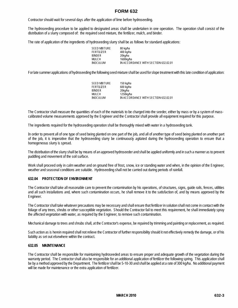
FORM 632
632-3MARCH 2010
Contractor should wait for several days after the application of lime before hydroseeding.
The hydroseeding procedure to be applied to designated areas shall be undertaken in one operation. The operation shall consist of thedistribution of a slurry composed of: the required seed mixture, the fertilizer, mulch, and binder.
The rate of application of the ingredients of hydroseeding slurry shall be as follows for standard applications:SEED MIXTUREFERTILIZERBINDERMULCHINOCULUM
80 kg/ha400 kg/ha20kg/ha1600kg/haIN ACCORDANCE WITH SECTION 632.02.01
For late summer applications of hydroseeding the following seed mixture shall be used for slope treatment with this late condition of application:
SEED MIXTUREFERTILIZERBINDERMULCHINOCULUM
150 kg/ha600 kg/ha20kg/ha1250kg/haIN ACCORDANCE WITH SECTION 632.02.01
The Contractor shall measure the quantities of each of the materials to be charged into the seeder, either by mass or by a system of mass-calibrated volume measurements approved by the Engineer and the Contractor shall provide all equipment required for this purpose.
The ingredients required for the hydroseeding operation shall be thoroughly mixed with water in a hydroseeding tank.
In order to prevent all of one type of seed being planted on one part of the job, and all of another type of seed being planted on another partof the job, it is imperative that the hydroseeding slurry be continuously agitated during the hydroseeding operation to ensure that ahomogeneous slurry is spread.
The distribution of the slurry shall be by means of an approved hydroseeder and shall be applied uniformly and in such a manner as to preventpuddling and movement of the soil surface.
Work shall proceed only in calm weather and on ground free of frost, snow, ice or standing water and when, in the opinion of the Engineer,weather and seasonal conditions are suitable. Hydroseeding shall not be carried out during periods of rainfall.
632.04 PROTECTION OF ENVIRONMENT
The Contractor shall take all reasonable care to prevent the contamination by his operations, of structures, signs, guide rails, fences, utilitiesand all such installations and, where such contamination occurs, he shall remove it to the satisfaction of, and by means approved by theEngineer.
The Contractor shall take whatever precautions may be necessary and shall ensure that fertilizer in solution shall not come in contact with thefoliage of any trees, shrubs or other susceptible vegetation. Should the Contractor fail to meet this requirement, he shall immediately spraythe affected vegetation with water, as required by the Engineer, to remove such contamination.
Mechanical damage to trees and shrubs shall, at the Contractor's expense, be repaired by trimming and painting or replacement, as required.
Such action as is herein required shall not relieve the Contractor of further responsibility should it not effectively remedy the damage, or of hisliability as set out elsewhere within the contract.
632.05 MAINTENANCE
The Contractor shall be responsible for maintaining hydroseeded areas to ensure proper and adequate growth of the vegetation during thewarranty period. The Contractor shall also be responsible for an additional application of fertilizer the following spring. This application shallbe by a method approved by the Department. The fertilizer shall be 5-10-30 and shall be applied at a rate of 300 kg/ha. No additional paymentwill be made for maintenance or the extra application of fertilizer.

FORM 632
632-4 MARCH 2010
632.06 CONTRACTOR'S WARRANTY PERIOD
All areas hydroseeded under this contract shall have a warranty period of one year starting from the date of initial acceptance. This warrantyshall cover any defects in materials and workmanship, and damages caused by the elements of weather. During this period, any defect broughtto the attention of the Contractor by the Engineer shall be fixed, repaired or made good to the satisfaction of the Engineer and at no additionalcost to the Department.
632.07 MEASUREMENT FOR PAYMENT
The slope area actually hydroseeded, from within the limits as staked by the Engineer, will be measured in square metres, rounded to thenearest whole number.
632.08 BASIS OF PAYMENT
Payment of the contract price for hydroseeding shall be compensation in full for all labour, materials and equipment-use for: supplying theinoculated seed mixture as specified; supplying the fertilizer, binder and mulch; carrying-out the hydroseeding operation; and supplying andplacing the fertilizer in the following spring; together with a one year warranty period, during which time the Contractor shall be responsible formaking good any defect to the growth of the vegetation.
Full payment shall not be made until the final acceptance of the work on satisfactory completion at the end of the warranty period. A holdbackin the amount of 15% of the total payment for hydroseeding in addition to the standard required 10% holdback shall be retained for the warrantyperiod.

FORM 701
MARCH 2010 701-1
SECTION 701 INTRODUCTION INDEX 701.01 SCOPE 701.02 FUNDAMENTAL PRINCIPLES 701.03 CLASSIFICATION OF TEMPORARY CONDITION SIGNS 701.04 SPECIFICATIONS 701.05 COLOURS AND SHAPES 701.06 DIMENSIONS OF ALL TEMPORARY CONDITION SIGNS 701.07 USE OF PORTABLE OR REMOVABLE SIGN SUPPORTS 701.08 PERMANENTLY INSTALLED TEMPORARY CONDITION SIGN SUPPORTS 701.09 MOUNTING CHEVRON AND HAZARD MARKERS ON REBAR FOR INSTALLATION ON
PAVED SURFACES 701.10 MOUNTING CHEVRON AND HAZARD MARKERS DURING WINTER SEASON 701.11 BASIS OF PAYMENT 701.01 SCOPE The provisions for public protection established herein are for application by contractors employed under contract by the Department of Transportation & Works. Traffic safety in construction zones should be an integral and high priority element of every project. The goal should be to route traffic through such areas, with temporary condition signs and devices, as nearly as possible comparable to those for normal situations. The responsibility for temporary condition signs and devices rests with the Contractor. Thus, while this specification provides standards for design and application of temporary condition signs and devices installation, it is not a substitute for good engineering judgment. The decision to use a particular device at a particular location should be made on the basis of an engineering study at the location. The provisions for public protection established herein are for application by contractors performing any work for the Department of Transportation & Works. All costs associated with temporary condition signing to standards as outlined in Division 7 shall be the responsibility of the Contractor. Cost of signs, handling, installation, materials, and labour shall be paid by the Contractor and no payment shall be considered by the Department of Transportation & Works. 701.02 FUNDAMENTAL PRINCIPLES 1. All traffic signs used for temporary conditions are designed and erected for the safety and
convenience of the travelling public and for the safety of the workmen on the construction projects. Additional information on temporary condition signage may be found in “Traffic Control Manual for Roadway Work Operations 2010 Field Edition.
2. The Project Engineer shall be contacted three weeks in advance for assistance in signing major
construction detours. 3. Work sites should be carefully checked to make sure that traffic controls are changed to suit
changing construction conditions due to work staging and progress, or if an immediate improvement to the traffic control is needed.
GOVERNMENT OF NEWFOUNDLAND AND LABRADOR Department of Transportation and Works Highway Design Division

FORM 701
MARCH 2010 701-2
4. All signs shall conform to the required standards in shape, colour, size and position as outlined in this division for Temporary Condition Signing and the Department of Transportation & Works Sign Manual.
5. All temporary condition signage anticipated to be in use for longer than five days in duration or
during a weekend period must be installed permanently as outlined in Section 701.08. Portable or removable types of mounting stands may only be used where signage is required for five days or less and are NOT permitted during a weekend period. Sign bases should not be appreciably wider than the signs, must be sound material and designed to adequately support the sign. Bases which require weighting so as not to turn over during wind conditions must be weighted using ONLY sand bags meeting the approval of the Engineer. The use of rocks, boulders, concrete blocks, or metal pieces shall not be permitted. When the sign is removed from the construction zone the sandbags must also be removed. Leaving sandbags along the shoulder of the highway is not permitted. Signs on portable or removable sign stands shall conform to Section 701.07 and must be approved by the Engineer.
6. Poorly maintained, defaced, damaged, or dirty temporary condition signs are ineffective and
shall be replaced, repaired, or cleaned without delay. Signs which have been defaced or damaged and are not replaced within 24 hours of notification shall be expropriated by the Department. All signage expropriated in this manner will remain the property of the Department of Transportation & Works.
7. No construction work will be permitted to commence until all traffic control devices are erected in
position, as shown in this Division and approved by the Engineer. 8. After a work zone is completed all traffic signs used on that construction zone shall be removed
immediately. Any erected signs not applicable during a phase of construction shall be removed or covered. The Department reserves the right to expropriate all highway signs that are left in place after the work zone is completed. In particular the Department especially focuses upon unwarranted and misused speed limit signage and flagperson signage. All signage expropriated in this manner will remain the property of the Department of Transportation & Works.
9. Objects within the roadway or immediately adjacent to the roadway, which constitute a hazard to
traffic shall be marked with "Hazard Markers". 10. Construction Speed Zones shall be implemented only as shown in this Division. 11. After dark all signs shall be checked for visibility and those that cannot be clearly seen shall be
cleaned, replaced, adjusted or illuminated. 12. The end of construction shall be clearly marked with Construction Ends sign TC-4 or custom
signage TC-200 NL.. The end of each construction zone shall be clearly marked with “Construction Zone Ends”.
13. Any signs not supplied by the Department of Transportation & Works shall meet all specifications
in this Division and the Sign Manual of the Department of Transportation & Works. 701.03 CLASSIFICATION OF TEMPORARY CONDITION SIGNS Regulatory Signs - are described in the Manual of Standard Signs and Devices, Department of Transportation & Works. Reference to regulatory signs in this part will be limited to their application on portions of roadway where construction activities or other temporary and unused conditions require road user response. Warning Signs - as described in this Division are temporary condition warning signs. Information Signs - are as described in the Manual of Standard Signs and Devices, Department of Transportation & Works. Reference to information signs in this part is limited to their application for guiding traffic through portions of roadway where construction activities or other temporary and unusual conditions may otherwise create confusion. Application for guiding traffic through detours associated with the above roadway conditions is also included. In all cases detour signing shall be continuous and complete to guide the road user back to his normal route.

FORM 701
MARCH 2010 701-3
701.04 SPECIFICATIONS Unless modified by the following, the specifications outlined in the Manual of Standard Signs and Devices or Metric Edition of Uniform Traffic Control Devices of Canada will apply to temporary conditions signs in all details concerning symbols, lettering, illumination, reflectorization, position, erection, material, support, and maintenance. One sign only shall be placed on each support with the exception of tab signs erected to provide supplementary or complementary information associated with warning signs or detour signs. 701.05 COLOURS, SHAPES AND MATERIALS Warning Signs - shall have black symbols or lettering on an orange retro-reflectorized background of 3M high intensity grade or equivalent. The use of fluorescent paint on signage shall not be considered. Regulatory and Information Signs - which may be used for temporary traffic control or guidance shall have the same colour and shape as described in the Manual of Standard Signs and Devices, Department of Transportation & Works. All temporary construction signage shall be made with a rigid backing consisting of either plywood or aluminum. Flexible or roll up type signs will not be permitted. 701.06 DIMENSIONS OF ALL TEMPORARY CONDITION SIGNS The size and dimensions of temporary condition signage shall be as described in the manual of Standard Signs, Department of Transportation & Works and shall be to approved methods as directed by the Engineer. 701.07 USE OF PORTABLE OR REMOVABLE SIGN SUPPORTS As outlined in Section 701.02.5, the use of portable or removable sign supports shall be permitted for temporary conditions not longer than five days in duration and not over a weekend period. Signs shall be located on the right side of the roadway with the near edge from 1.5 m to 4 m from the edge of the travelled portion of the roadway. Supplementary signs will be located on the left hand side of the roadway on divided highways. Signs 900 mm or less in width shall be erected on a single post to a height of 1.5 m to 2.5 m above the travelled portion of roadway to the bottom edge of the sign. Signs exceeding 900 mm in width shall be erected on two posts at a general height of 1.5 m above the travelled portion of the roadway to the bottom edge of the sign. Signs 1200 mm x 1200 mm may be installed on portable stands so that the bottom of the sign is approximately 1.0 m above the travelled portion of the roadway. Signs on portable stands, which are ONLY used during daylight hours may reduce this mounting height to 450 mm above the travelled portion of the roadway. To compensate for their extremely low mounting height, supports should be located with a minimum of 1 m from the edge of the travelled portion of the roadway. Signs used in this manner shall have two red flags mounted on the top of the sign to compensate for their reduced mounting height. Delineation devices are to be mounted as per Form 710. 701.08 PERMANENTLY INSTALLED TEMPORARY CONDITION SIGN SUPPORTS As outlined in Section 701.02.05, all construction signage intended to remain in a fixed location for longer than five days or over a weekend period shall be installed on a permanent, rigid sign post. Signs shall be located on the right side of roadway with the near edge from 1.5 m to 4 m from the edge of the travelled portion of the roadway. Supplementary signage shall be located on the left hand side of the roadway on divided highways. Signs 1200 mm or less in width/length shall be erected on a single post to a height of 1.5 m to 2.5 m above the travelled portion of the roadway to the bottom edge of the sign. Most signs in this category can be securely installed on 100 mm x 100 mm wooden posts with a minimum of 1 m of the post in the ground. Care should be exercised to ensure that the post is securely anchored in the ground, so that it cannot be "turned" or removed by vandals. Signs longer than 1200 mm in width/length shall be installed according to guidelines in Section 580 - Sign and Signpost Installations for the corresponding size of the sign.

FORM 701
MARCH 2010 701-4
701.09 MOUNTING CHEVRON AND HAZARD MARKERS ON REBAR FOR INSTALLATION ON PAVED SURFACES Where traffic has to be diverted or channelized to cross multi-lanes of paved surfaces, delineator devices, such as hazard markers and chevrons, shall be installed as outlined in this section. Signs 300 mm or less in width, shall be erected on a single piece of 25 mm rebar to a height of 1 m to 2 m above the travelled portion of the roadway to the bottom edge of the sign. Signs greater than 300 mm in width, shall be erected on two pieces of 25 mm rebar to a height of 1 m to 2 m above the travelled portion of the roadway to the bottom edge of the sign. 701.10 MOUNTING CHEVRON AND HAZARD MARKERS DURING WINTER SEASON Signs are to be mounted on rebar or wooden posts in order to delineate traffic through a merger of a major route, after construction has ended. Signs shall be installed as outlined in section’s 701.08 and 701.09. 701.11 BASIS OF PAYMENT All costs associated with temporary condition signing to standards as outlined in this section shall be the responsibility of the Contractor. Costs of the signs, handling, installation, removal, asphalt reinstatement and / or repair, materials, and labour shall be paid by the Contractor and no payment shall be considered by the Department of Transportation & Works.

FORM 903
903-1
GOVERNMENT OF NEWFOUNDLAND AND LABRADORDepartment of Transportation and WorksHighway Design Division
SECTION 903CONSTRUCTION SPECIFICATION FOR PILING
INDEX903.01 SCOPE903.02 MATERIALS
903.02.01 Timber - Round Piles903.02.02 Steel Sheet Piles and H-Piles903.02.03 Steel Tube Piles903.02.04 Pile Tips903.02.05 Concrete And Reinforcement For Steel Tube Piles903.02.06 Storage And Handling
903.03 PILE DRIVING903.03.01 General Requirements And Restrictions903.03.02 Tolerances903.03.03 Driving Equipment903.03.04 Jetting903.03.05 Helmets903.03.06 Records903.03.07 Redriving903.03.08 Driving Of Tube And H-Piles When Boulders Are Anticipated Or Driving To Bedrock
903.04 SPLICES903.04.01 Timber Piles903.04.02 Steel Piles
903.05 CONCRETE FILL IN TUBULAR STEEL PILES903.06 UNASSIGNED903.07 UNASSIGNED903.08 MEASUREMENT FOR PAYMENT
903.08.01 Sheet Piles Supplied903.08.02 Piles Other Than Sheet Piles Supplied
903.08.03 Sheet Piles Installed 903.08.04 Piles Other Than Sheet Piles Installed
903.08.05 Pile Tips And Splices903.08.06 Rejection903.08.07 Vertical Piles903.08.08 Battered Piles
903.09 BASIS OF PAYMENT903.09.01 Sheet Piles Supplied903.09.02 Piles Other Than Sheet Piles Supplied
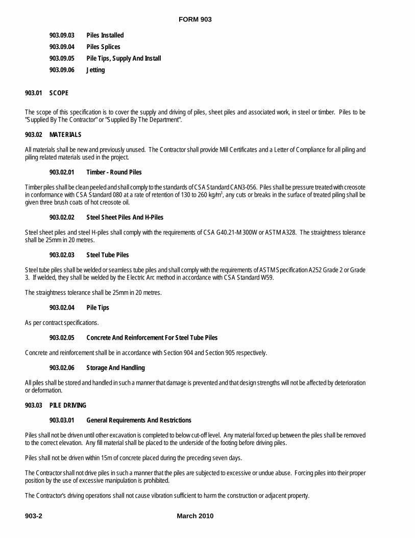
FORM 903
March 2010903-2
903.09.03 Piles Installed903.09.04 Piles Splices903.09.05 Pile Tips, Supply And Install903.09.06 Jetting
903.01 SCOPE
The scope of this specification is to cover the supply and driving of piles, sheet piles and associated work, in steel or timber. Piles to be"Supplied By The Contractor" or "Supplied By The Department".
903.02 MATERIALS
All materials shall be new and previously unused. The Contractor shall provide Mill Certificates and a Letter of Compliance for all piling andpiling related materials used in the project.
903.02.01 Timber - Round Piles
Timber piles shall be clean peeled and shall comply to the standards of CSA Standard CAN3-056. Piles shall be pressure treated with creosotein conformance with CSA Standard 080 at a rate of retention of 130 to 260 kg/m3, any cuts or breaks in the surface of treated piling shall begiven three brush coats of hot creosote oil.
903.02.02 Steel Sheet Piles And H-Piles
Steel sheet piles and steel H-piles shall comply with the requirements of CSA G40.21-M 300W or ASTM A328. The straightness toleranceshall be 25mm in 20 metres.
903.02.03 Steel Tube Piles
Steel tube piles shall be welded or seamless tube piles and shall comply with the requirements of ASTM Specification A252 Grade 2 or Grade3. If welded, they shall be welded by the Electric Arc method in accordance with CSA Standard W59.
The straightness tolerance shall be 25mm in 20 metres.
903.02.04 Pile Tips
As per contract specifications.
903.02.05 Concrete And Reinforcement For Steel Tube Piles
Concrete and reinforcement shall be in accordance with Section 904 and Section 905 respectively.
903.02.06 Storage And Handling
All piles shall be stored and handled in such a manner that damage is prevented and that design strengths will not be affected by deteriorationor deformation.
903.03 PILE DRIVING
903.03.01 General Requirements And Restrictions
Piles shall not be driven until other excavation is completed to below cut-off level. Any material forced up between the piles shall be removedto the correct elevation. Any fill material shall be placed to the underside of the footing before driving piles.
Piles shall not be driven within 15m of concrete placed during the preceding seven days.
The Contractor shall not drive piles in such a manner that the piles are subjected to excessive or undue abuse. Forcing piles into their properposition by the use of excessive manipulation is prohibited.
The Contractor's driving operations shall not cause vibration sufficient to harm the construction or adjacent property.

FORM 903
March 2010 903-3
903.03.02 Tolerances
Piles shall be driven as nearly as possible in the exact position specified on the drawings. After driving, piles at the cut-off elevation shall notbe more than 75mm from the location shown on the drawings.
Deviation from the vertical or required batter shall not be more than 20mm per lineal metre of pile. Any pile so out of line or plumb as to impairits usefulness shall be pulled and redriven or an additional pile shall be driven as required by the Engineer. The piles shall not be jacked orpulled laterally to bring their tops into correct location.
903.03.03 Driving Equipment
All piles shall be driven with a hammer developing an energy per blow of not less than that shown in the contract document. The energy shouldbe capable of remote regulation to prevent damage to the piles. The piles and hammer shall be held securely in the correct alignment by rigidleads extending down to the lowest point the hammer must reach.
903.03.04 Jetting
Jetting shall not be used unless written permission has been given by the Engineer. Appropriate special conditions will be given should jettingbe authorized.
903.03.05 Helmets
Pile heads shall be protected by helmets having adequate cushioning material next to the pile head. The helmet shall distribute the blow ofthe hammer evenly throughout the pile cross-section.
Timber piles shall be prevented from splitting by collars.
903.03.06 Records
The Contractor shall not commence driving piles in the absence of the Engineer.
Blows per 300mm for each 300mm shall be recorded. For the final 300mm the blows per 25mm shall be recorded.
When driving is interrupted before final penetration is reached, the final record of penetration shall not be taken until, on resumption of driving,a further penetration of 300mm has been obtained.
903.03.07 Redriving
Piles pushed up by driving or loosened by jetting of adjacent piles shall be redriven to comply with the requirements of the contract. Similarly, ifa pile(s) is suspected to have hung up on a boulder, the Contractor shall re-drive the pile(s) in question as well as others in the immediate vicinity.
After all piling is complete and all piles are driven to meet project criteria, the contractor shall return to each footing and re-drive at least ten(10) percent of the piles in each footing rounded to the next highest number of piles plus one. The piles selected for re-driving shall berandomly selected by the Engineer. If movement exists on one or more piles, additional piles shall be re-driven until the Engineer is satisfiedthat all piles have met the design criteria as established on the contract drawings or in the specifications.
The contractor is advised that piling shall not be cut-off until all re-driving is complete.
903.03.08 Driving Of Tube And H-Piles When Boulders Are Anticipated Or Driving To Bedrock
When boulders are anticipated, pile tips should be fitted. Driving shall be carried out until the pile tips make contact with rock. Driving energyshall be decreased to about a quarter and the pile shall be subjected to twenty blows. Energy can be increased with approval from theEngineer by about a quarter at twenty blows for each interval until the Engineer is satisfied that the requirements of the contract are compliedwith. Adjacent piles should then be redriven
When steel tube and H-piles are to be driven to and chipped or socketed into bedrock, rock injector pile tips shall be fitted to the ends of thepiles. The piles shall be chipped into the bedrock using low energy. When the piles are firmly seated, the energy shall be increased in stagesor intervals and eventually driven to refusal at the rated energy as stipulated in the contract documents.

FORM 903
March 2010903-4
903.04 SPLICES
903.04.01 Timber Piles
No splices will be permitted for timber piles.
903.04.02 Steel Piles
No splices will be permitted for steel piles except where allowed for in the contract or as authorized by the Engineer in exceptionalcircumstances. In no event will more than two splices per pile be allowed.
Welding shall meet the requirements of CSA Standard W59 and shall be done by a welder qualified according to CSA Standard W47.1.Welding details shall be submitted to and approved by the Engineer.
903.05 CONCRETE FILL IN TUBULAR STEEL PILES
After acceptance by the Engineer, the pile shells including rejected shells left in the ground shall be cut off at the required elevation and shallbe filled with concrete.
Prior to filling each pile, the inside shall be inspected with an electric lamp attached to a drop cord of sufficient length to reach the bottom ofthe pile. Any debris and water shall be removed before placing the concrete.
Reinforcing steel shall be installed in the concrete fill at the top of all the piles as shown on the drawings.
No concrete shall be placed until all driving within a radius of 15m has been completed. If this cannot be done, driving within these limits shallbe stopped until the concrete in the last pile has set for at least seven days.
Concrete shall be placed continuously until the shell is filled.
The concrete shall be worked thoroughly down into place and compacted with a vibrator to the lowest extent of the reinforcement.
After placing, the concrete shall be protected from frost for at least three days.
903.08 MEASUREMENT FOR PAYMENT
903.08.01 Sheet Piles Supplied
The measurement for sheet piles supplied will be in square metres to the nearest one decimal place. For payment purposes the measurementfor sheet piles supplied will be based upon the actual quantity installed provided this quantity equals or exceeds the quantity estimated in theStructure Unit Price Table. If the actual quantity installed is less than the quantity estimated then payment will be made for supplying the quantityinstalled plus the total area of unused sheet piles but not exceeding the estimated quantity. Unused sheet piles will include only uncut sheet pilesin lengths originally supplied to the Contractor and, if necessary, cut-off sections of sheet pile whose lengths are 3 m or longer. For paymentpurposes the length of cut off sections will be calculated based upon the difference between the estimated pile toe elevation as shown on the contractdrawings and the actual pile toe elevation.
903.08.02 Piles Other Than Sheet Piles Supplied
The measurement for piles supplied other than sheet piles will be in linear metres to the nearest one decimal place. For payment purposesthe measurement for piles supplied other than sheet piles will be based upon the actual quantity installed provided this quantity equals orexceeds the quantity estimated in the Structure Unit Price Table. If the actual quantity installed is less than the quantity estimated then paymentwill be made for supplying the quantity installed plus the total length of unused piles but not exceeding the estimated quantity. Unused piles willinclude only uncut piles in lengths originally supplied to the Contractor and, if necessary, cut-off sections of piles whose lengths are 3 m or longer.For payment purposes the length of cut off sections will be calculated based upon the difference between estimated pile toe elevation as shown onthe contract drawings and the actual pile toe elevation.
903.08.03 Sheet Piles Installed
The measurement for sheet piles installed will be in square metres to the nearest one decimal place based upon the actual quantity of pileinstalled and left in place after cut off as approved by the engineer.
903.08.04 Piles Other Than Sheet Piles Installed

FORM 903
March 2010 903-5
The measurement for piles other than sheet piles installed will be in linear metres to the nearest one decimal place based upon the actualquantity of pile installed and left in place after cut off as approved by the engineer..
903.08.05 Pile Tips And Splices
These will be measured according to the actual number used, authorized and accepted by the Engineer.
903.08.06 Rejection
Any piles or tips which are rejected for reasons of improper driving, positioning or damage shall not be included in the above measurements.
903.08.07 Vertical Piles
All piles shown on the plans vertically will be considered and paid for as vertical piles.
903.08.08 Battered Piles
All piles shown on the plans with a batter angle will be considered and paid for as battered piles.
903.09 BASIS OF PAYMENT
903.09.01 Sheet Piles Supplied
Payment at the contract price for sheet piles supplied shall be full compensation for all labour, materials, supplies and equipment required tocomplete the work associated with the supply of piling, loading and transportation to the jobsite, unloading, handling and storage of piling materials.
Unused sheet piles shall be loaded, transported and off-loaded by the Contractor to a designated area at the nearest maintenance depot as partof the demobilization item as per section 157 of the Specifications Book. When the Contractor transports the unused piles he shall present areceipt for the piles, signed by the Depot Foreman, to the Engineer.
The quantity of wastage (defined as the quantity supplied to the site less the pay quantity) shall be the Contractor's responsibility and paymentwill not be made for such. The Engineer shall determine the quantity of wastage.
903.09.02 Piles Other Than Sheet Piles Supplied
Payment at the contract price for piles other than sheet piles supplied shall be full compensation for all labour, materials, supplies and equipmentrequired to complete the work associated with the supply of piling, loading and transportation to the jobsite, unloading, handling and storage of pilingmaterials.
Unused piles shall be loaded, transported and off-loaded by the Contractor to a designated area at the nearest maintenance depot as part of thedemobilization item as per section 157 of the Specifications Book. When the Contractor transports the unused piles he shall present a receipt forthe piles, signed by the Depot Foreman, to the Engineer.
The quantity of wastage (defined as the quantity supplied to the site less the pay quantity) shall be the Contractor's responsibility and payment willnot be made for such. The Engineer shall determine the quantity of wastage. to the Engineer.
903.09.03 Piles Installed
Payment at the contract price per square meter for sheet piles installed and per linear meter for piles other than sheet piles installed shall be fullcompensation for positioning, driving, cleaning, painting, protecting and pile cut-off.
The re-driving of piles shall be considered incidental to the work and extra payment will not be made for the same. However, where the contractorsucceeds in increasing the length of piling in the works he shall be compensated for supply and installation in accordance with the contractspecifications.
Where pile capacity is established by dynamic analysis and relaxation occurs the Contractor shall have the pile capacity re-evaluated. Piles are definedto have relaxed when more than 125 mm average movement occurs in those piles subject to re-driving as defined in Section 903.03.07 above.Dynamic analysis re-evaluation shall be conducted by an agency approved by the Engineer. The cost of the dynamic analysis re-evaluation shall bepaid for by the Department. All other costs including but not limited to the cost of delay shall be considered incidental to the tendered price for pilesdriven.
No payment will be made for falsework piling.

FORM 903
March 2010903-6
All costs involved in filling tube piles with concrete and reinforcing shall be included in the contract price for piles installed.
Payment for pile template(s) shall be considered incidental to the work and payment will not be made for such.
903.09.04 Pile Splices
Payment at the contract price shall be full compensation for all labour, equipment, materials and services necessary to install pile splices whereapproved.
903.09.05 Pile Tips, Supply And Install
Payment at the contract price shall be full compensation for all labour, equipment and materials necessary to supply, deliver and install the pile tips.
903.09.06 Jetting
No additional payment shall be made for jetting, if authorized.0

FORM 904
March 2010 904-1
GOVERNMENT OF NEWFOUNDLAND AND LABRADORDepartment of Transportation and WorksHighway Design Division
SECTION 904CONCRETE STRUCTURES
INDEX904.01 SCOPE904.02 MATERIALS
904.02.01 Cement904.02.02 Aggregate904.02.03 Water904.02.04 Air Entraining Agent904.02.05 Admixtures904.02.06 Reinforcement904.02.07 Formwork and Falsework904.02.08 Burlap904.02.09 Filter Fabric904.02.10 Moisture Barrier904.02.11 Miscellaneous Materials
904.03 EQUIPMENT904.04 CONCRETE PRODUCTION, DELIVERY AND PLACING
904.04.01 Measurement of Materials904.04.02 Concrete Quality904.04.03 Mixing Concrete904.04.04 Placing Concrete904.04.05 Depositing Concrete Under Water904.04.06 Mass Concrete904.04.07 Construction Joints904.04.08 Contraction Joints904.04.09 Concrete Beam Seats and Bearing Surfaces904.04.10 Tolerances904.04.11 Confilm904.04.12 Caulking of Joints
904.05 CURING904.05.01 Fog Misting of Bridge Decks904.05.02 Moist Curing904.05.03 Air Drying904.05.04 Plastic Shrinkage904.05.05 Liquid Membrane Curing
904.06 HOT WEATHER CONCRETING

FORM 904
March 2010904-2
904.07 COLD WEATHER CONCRETING904.07.01 General904.07.02 Placing904.07.03 Protecting Placed Concrete904.07.04 Heating the Protective Housing
904.08 SURFACE FINISHING904.09 SAMPLING AND TESTING904.10 MEASUREMENT FOR PAYMENT
904.10.01 Measurement for Payment for concrete work where the Unit Price Table states the unit to be cubic metres.904.10.02 Measurement for Payment for concrete work where the Unit Price Table states the unit to be a unit other than
cubic metres.904.11 BASIS OF PAYMENT
904.11.01 Basis of Payment for concrete work where the Unit Price Table states the unit to be cubic metres.904.11.02 Basis of Payment for concrete work where the Unit Price Table states the unit to be a unit other than cubic
metres.904.11.03 Concrete Acceptance and Reduced Payment Criteria on Concrete Located in New Structures904.11.04 Concrete Acceptance and Reduced Payment Criteria on Concrete Located in Rehabilitated Structures
904.01 SCOPE
The scope of this specification is to cover the supply of materials for concrete structures, production, delivery, placement, sampling and testingof concrete, curing, and the subsequent protection. All work, plant, equipment and materials shall be in strict accordance with CSA StandardCAN/CSA A23.1-M.
The plant from which the ready mix concrete is supplied shall be certified in accordance with the requirements for certification as publishedby the Atlantic Provinces Ready Mix Concrete Association or equivalent. A copy of the certification of conformance shall be provided to theEngineer prior to the start of delivery under the proposed contract.
In the event that the contractor selects a ready mixed concrete supplier not certified by APRMCA, approval must be obtained from the MaterialsEngineering Division at least 14 days prior to concrete supply.
A job meeting shall be held prior to the deck concrete placement to discuss all aspects of the concrete work including production, supply,delivery, placing, curing and any other related items. This meeting is to be called by the Engineer; the Contractor and all others deemednecessary by the Engineer shall be in attendance.
904.02 MATERIALS
All concrete materials shall be in accordance with CSA Standard CAN/CSA-A23.1-M.
904.02.01 Cement
All cementing materials shall be in accordance with CAN/CSA A3000.
Cement for Superstructure, Substructure, MSE Panels and Reinforced Wharf Deck Concrete (with the exception of Pile, Mass and TremieConcrete) shall be a blended Portland, fly ash, silica fume cement, Type GUbF/SF. Contractors are advised that the minimum proportion bymass of the total cementing materials for silica fume shall be 6% and a maximum of 8%. Contractors are advised that the maximum proportionby mass of the total cementing materials for fly ash is 25%.
Cement for deck and curb resurfacing in Section 919 Rehabilitation of Concrete Structures shall shall be Portland cement Type GU unlessotherwise specified.

FORM 904
March 2010 904-3
Cement for all other concrete shall be Portland cement Type GU, a portion of which may be replaced by fly ash up to 10% by mass of the totalcementing material.
904.02.02 Aggregate
The source of the aggregate will be determined by the Contractor but all aggregate shall meet the requirements of CSA Standard CAN/CSA-A23.1-M. The maximum petrographic number will be 135.
Concrete aggregate shall consist of natural sands and gravels, crushed rock or other inert materials having clean, uncoated grains of strongand durable minerals.
Fine and coarse aggregate shall be stored in separate stock piles sufficiently removed from each other to prevent the materials at the edgesof the piles from becoming intermixed.
Aggregate shall be free from alkali, organic matter or other deleterious substances and shall not contain soft, friable, thin, flaky, elongated orlaminated particles totalling more than 3% nor contain shale in excess of 1½%, nor silt and crusher dust finer than 75:m sieve size, in excessof 2%. The percentages shall be based on the weight of the combined aggregate as used in the concrete. When all three groups of thesedeleterious materials are present, the combined amounts shall not exceed 5% by weight of the combined aggregate.
The maximum size of stone to be used for the different thickness of concrete shall be 20mm unless otherwise ordered by the Engineer. Inno case shall the maximum size of stone used be greater than either 2/3 the clear distance between the reinforcement or 2/3 the clear distancebetween the exterior bars and the face of the structure except for girders where the latter criteria shall be 0.8 times the clear distance betweenthe exterior bars and the face of the structure.
Stock piles of approved fine and coarse aggregate, in amounts of one quarter to one half of that required for the job, shall be placed on thesite of the work at least one month previous to concrete placing operations. The stockpiles shall be protected by tarpaulins or plastic sheetingagainst formations of ice and accumulation of snow.
The Contractor shall provide with the concrete mix design relevant test data for all aggregate materials indicating conformance to therequirements of CSA-A23.1 and this specification. The sources and test results of all aggregate materials shall be clearly identified. Theaggregate tests shall be conducted by a testing laboratory CCIL or CSA Certified in accordance with CSA Standard A-283-06 or latest edition.Test results are only considered valid for up to two years in advance of the date of the project mix design submission. The test data requiredbut not be limited to shall include:
- Sieve Analysis of Fine and Coarse aggregate CSA-A23.2-2A- Amount of Material Finer than 75 :m in Aggregate CSA-A23.2-5A- Bulk Relative Density and Absorption of Fine and Coarse Aggregate (SSD basis) CSA-A23.2-6A- Fineness Modulus of Fine Aggregate CSA-A23.2-2A- Clay Lumps and Light Weight Pieces CSA-A23.2-3A- Test for Organic Impurities in Fine Aggregate CSA-A23.2-7A- Flat and Elongated Particles in Coarse Aggregates CSA-A23.2-13A- Petrographic Analysis of Coarse Aggregate CSA-A23.2-15A- Resistance to Degradation of Coarse Aggregate by Abrasion and Impact in the Los Angelesmachine CSA-A23.2-16A- Micro-Deval test for Coarse and Fine Aggregate CSA-A23.2-23A and 29A- Soundness of Coarse & Fine Aggregate by Use of Magnesium Sulphate CSA-A23.2-9A- Test for Detection of Alkali-Aggregate Reactivity (AAR) on Coarse and Fine Aggregate CSAA23.2-25A - Unconfined Freeze Thaw test CSA-A23.2-24A
904.02.03 Water
All water shall be clear and free from injurious substances and shall be potable.
All water used for curing shall be clean and free of any material which would cause staining or discoloration of the concrete. Thecontractor shall not use water from shallow, stagnant or marshy sources.
904.02.04 Air Entraining Agent
All concrete shall be air entrained with the air entraining agent conforming to CSA Standard CAN3-A266.1-M.

FORM 904
March 2010904-4
904.02.05 Admixtures
Any other admixture must be approved by the Engineer and shall conform to CSA Standard CAN3-A266.2-M.
904.02.06 Reinforcement
Reinforcement shall conform to Section 905, "Concrete Reinforcement".
904.02.07 Form work and Falsework
Form work and falsework shall conform to Section 907, "Form work and Falsework".
904.02.08 Burlap
Burlap shall conform to AASHO M182 "Specification for Burlap Cloth made from Jute or Kenaf".
904.02.09 Filter Fabric
Filter fabric shall be a, non woven geotextile with a minimum mass of 340gm/m² and a minimum thickness of 3.3mm; all properties testedin accordance with C.G.S.B. CAN 24.2-M77 test methods.
Filter fabric or non-woven geotextile may be used for curing on flat horizontal surfaces but not on vertical surfaces. Vertical surfaces, i.e.abutments shall be cured using saturated burlap only.
904.02.10 Moisture Barrier
Moisture barrier shall conform to ASTM C171, "Sheeting Materials for Curing Concrete".
904.02.11 Miscellaneous Materials
The supply and installation of miscellaneous materials shown on the drawings or mentioned in the Supplementary General Conditions but whichhave not been listed on the Unit Price Table, are considered incidental to the work and no separate payment will be made.
This shall include, but not necessarily limited to, all miscellaneous concrete accessories, Confilm evaporation retardant, abutment weep holes,drip grooves and guide rail modified end shoes.
904.02.12 Membrane Curing Compounds
Membrane curing compounds shall meet the requirements of ASTM C309, and shall only be used with the approval of the Engineer.
904.03 EQUIPMENT
The Contractor shall supply the Engineer before commencement of the project with adequate details of all equipment to be used. The intentionis not to limit the Contractor's operation but to ensure adequate planning is undertaken.
The Contractor shall maintain all equipment used for handling, mixing, transporting, depositing, compacting, curing and finishing the concretein a clean condition and in proper working order.
Pumping equipment may be utilized by the Contractor. Details of the pumping equipment and operation must be approved by the Engineer.The Contractor shall submit to the Engineer, manufacturer's specifications detailing pumping capacity and pressure at the required elevations.Aluminum pipelines shall not be used. The Contractor shall be prepared in the event of a breakdown in pumping operations. These emergencypreparations shall be discussed with and approved by the Engineer prior to the commencement of concrete placement utilizing pumpingequipment.
Compaction equipment shall be capable of giving dense concrete in accordance with specification requirements. Internal vibrators shall havea frequency of 160 Hz.
An approved self-propelled mechanical bridge deck finisher shall be used to strike off and finish concrete decks as per specifications. Theapproved machine shall travel on guides or rails supported so that they are completely clear of the finished surface. The guide or rail supportsthat extend through the roadway areas of the deck shall be such that they can be removed to at least 50mm below the top of concrete. Two

FORM 904
March 2010 904-5
work platforms shall be used for finishing and curing operations.
Batching equipment shall be as defined in Section 904.04.03, "Mixing Concrete".
The equipment required for heating materials for Cold Weather Concreting shall be of adequate capacity and be approved by the Engineer;it shall be available, installed and tested ready for use before it is proposed to place concrete. Heating equipment shall be ready for usebetween September 1 and April 30 when so required by the Engineer. Alternative methods of keeping concrete temperatures at acceptablelevels may be approved. Where the heating equipment is to be used for heating the housing as well as the materials at the same time, theterm adequate capacity means that the equipment shall have adequate capacity to heat both materials and housing simultaneously to therequired temperature.
Boilers used for heating materials or housing shall meet the inspection requirements and operating conditions laid down by Provincial Actsand Regulations.
904.04 CONCRETE PRODUCTION, DELIVERY AND PLACING
904.04.01 Measurement of Materials
Materials shall be measured by weighing. Other methods shall be used only if specifically authorized, in writing, by the Engineer.
The apparatus provided for weighing the aggregate shall be suitably designed and constructed for this purpose. Each size of aggregate shallbe weighed separately with a required accuracy of two per cent.
Cement in standard bags need not be weighed.
The mixing water shall be measured by volume or by weight.
All measuring devices shall be subject to approval of the Engineer.
904.04.02 Concrete Quality
Concrete strength shall be as shown on the drawings unless particular specifications require higher strength.
Concrete mixes shall be designed in accordance with CSA Standard CAN/CSA-A23.1 latest edition. Note that ACI standard 211.1 should beused as a guide for determining mix proportions for normal and mass concrete. Verification of the following specified properties through trialbatching will be a requirement as a prerequisite to approval of the mix design. In addition, test cylinders may be requested by the Engineerprior to approval of the concrete mix design.
PARAMETER SUPERSTRUCTURE45MPa (1,4)
SUBSTRUCTURE40MPa (1,4)
SUBSTRUCTURE &REINFORCED WHARF
DECK CONCRETE
PILECONCRETE
MASS & TREMIECONCRETE (2)
WATER/CEMENT RATIO 0.35 MAX. 0.37 MAX. 0.39 MAX. 0.45 MAX. 0.55 MAX.
SLUMP AS PER APPROVEDMIX DESIGN
AS PER APPROVEDMIX DESIGN
AS PER APPROVEDMIX DESIGN 100 + 30 mm* 100 + 30 mm*
COMPRESSIVE STRENGTH AT 28 DAYS 45 MPA 40 MPA 35 MPA 25 MPA 20 MPA
RAPID CHLORIDE PERMEABILITY(ASTM C1202) <1000 COULOMBS <1000 COULOMBS <1000 COULOMBS N/A N/A
AIR CONTENT 6 + 1%* 6 + 1%* 6 + 1%* 4 + 1%* 4 + 1%*
AIR VOID SPACING FACTOR (AVERAGE) 230 µM MAX. 230 µM MAX. 230 µM MAX. N/A N/A
SPECIFIC SURFACE (AVERAGE) 25 mm2/mm3 MIN. 25 mm2/mm3 MIN. 25 mm2/mm3 MIN. N/A N/A
* The above specified tolerances apply to concrete mix production and not to concrete mix design.
NOTES:1. The cementing materials content for 40 and 45 MPa concrete is 480 kg/m3 maximum.2. Tremie concrete shall require an additional 10% cement and slump shall be 180+30mm.3. Concrete for severe exposure conditions (decks, curbs, sidewalks, end blocks, barriers and grade separation columns) which containssuperplasticizer as an admixture to produce flowable concrete, shall have an air content 7 + 1%.

FORM 904
March 2010904-6
4. The above mix parameters do not include required adjustments for prestressed girder concrete.5. N/A - Not applicable
The Contractor will be responsible for the mix design and quality control of concrete production.
The Department will review and approve mix designs and provide quality assurance with regard to concrete testing. All concrete mix designproportioning including the mix quality control operations shall be performed by a Laboratory CCIL or CSA Certified in accordance with CSAStandard A-283 latest edition. All testing shall be as conducted as stated in CAN/CSA-A23.1 and A23.2 latest edition. The proposed mixturedesign shall be signed by a Professional Engineer registered to practice in Newfoundland and Labrador. The Professional Engineer shall attestto the validity of the material test data. Proposed mix designs and test results are only considered valid for up to two years in advance of thedate of the project mix design submission. The Contractor shall provide with the proposed mix design the following information based on actualtrial mixes at least two weeks in advance of concrete placement:
- Slump CSA A23.2-5C- Air Content of Plastic Concrete by Pressure Method CSA A23.2-4C- Mass Density and Yield CSA A23.2-6C- Compressive Strength Testing CSA A23.2-9C- Air Void Analysis on Hardened Concrete tested at 7 days ASTM C457- Electrical Indication of Concrete’s Ability to Resist Chloride Ion Penetration tested at 56 daysASTM C1202- Alkali Reactivity Test Results A23.2-25A
Also to be included with each mix design submission is the following necessary information:
- Project number and title description - Contractor company name with contact information- Ready mix supplier - Certifying laboratory with signing engineer- Type of concrete, intended use, approximate quantity and method of placement- Mix slump and air entraining agent range plus all admixtures with dosage rates- Aggregate test information as per requirements of 904.02.02 Aggregates
No concrete shall be placed until approval of the mix design has been obtained from the Engineer. The Contractor shall submit copies of theconcrete mix design 14 days in advance of any concrete placement operation.
Once approved, no adjustments shall be made to the concrete mix design without the approval of the Engineer. If material characteristicschange after the original mix design approval a revised mix design shall be submitted for approval.
Acceptance by the Engineer of the Contractor's concrete mix design does not relieve the Contractor of the responsibility for providing concretewhich meets the specifications.
High range water reducing agents (superplasticizers) may be used at the Contractor's request, if so indicated when the mix design is submitted.The Contractor must demonstrate competence and experience in their use and specific approval must be obtained. The Contractor shall statehis method of concrete placement when submitting his concrete mix design.
Where 40 and 45 MPa concrete is specified on the contract drawings, a trial batch consisting of a minimum of 20 m3 of superstructure concreteshall be placed in the substructure, i.e. abutments and footings, at least 28 days prior to the placement of any 40 or 45 MPa superstructureconcrete. The purpose of this exercise is to allow for fine tuning of the mix to achieve proper air and slump, and to obtain an early indicationof the expected compressive strength. The additional cost of this trial batch and fine tuning of the mix design shall be considered incidentalto the works.
If superplasticizers are used, the maximum concrete slump in a superplasticized condition shall be limited to 230 mm. The mix design shallstate the design slump before and after the addition of superplasticizers along with the appropriate tolerances. Note that the slump in the abovetable may not be applicable when using superplasticizers.
Samples for concrete testing quality assurance purposes will normally be taken from concrete as delivered to the site (at the point of dischargefrom the delivery equipment). However, depending on the method of placement, random sampling of the concrete as incorporated into thestructure may also be performed to verify the above specified properties. This process shall entail the sampling of fresh concrete as close tothe point of deposit in the structure as is practicable. Coring of the in-place hardened concrete may also be performed to verify the specifiedair void system. The Department reserves the right to designate the point of acceptance, with prior notice given to the Contractor.
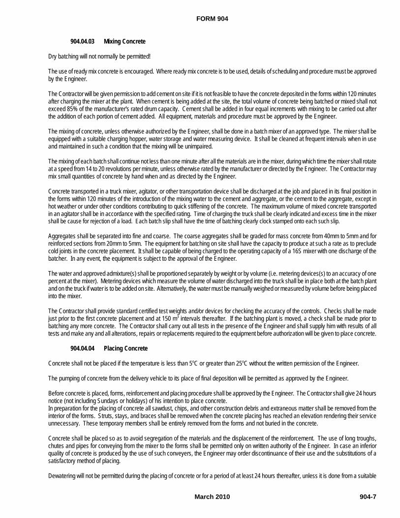
FORM 904
March 2010 904-7
904.04.03 Mixing Concrete
Dry batching will not normally be permitted!
The use of ready mix concrete is encouraged. Where ready mix concrete is to be used, details of scheduling and procedure must be approvedby the Engineer.
The Contractor will be given permission to add cement on site if it is not feasible to have the concrete deposited in the forms within 120 minutesafter charging the mixer at the plant. When cement is being added at the site, the total volume of concrete being batched or mixed shall notexceed 85% of the manufacturer's rated drum capacity. Cement shall be added in four equal increments with mixing to be carried out afterthe addition of each portion of cement added. All equipment, materials and procedure must be approved by the Engineer.
The mixing of concrete, unless otherwise authorized by the Engineer, shall be done in a batch mixer of an approved type. The mixer shall beequipped with a suitable charging hopper, water storage and water measuring device. It shall be cleaned at frequent intervals when in useand maintained in such a condition that the mixing will be unimpaired.
The mixing of each batch shall continue not less than one minute after all the materials are in the mixer, during which time the mixer shall rotateat a speed from 14 to 20 revolutions per minute, unless otherwise rated by the manufacturer or directed by the Engineer. The Contractor maymix small quantities of concrete by hand when and as directed by the Engineer.
Concrete transported in a truck mixer, agitator, or other transportation device shall be discharged at the job and placed in its final position inthe forms within 120 minutes of the introduction of the mixing water to the cement and aggregate, or the cement to the aggregate, except inhot weather or under other conditions contributing to quick stiffening of the concrete. The maximum volume of mixed concrete transportedin an agitator shall be in accordance with the specified rating. Time of charging the truck shall be clearly indicated and excess time in the mixershall be cause for rejection of a load. Each batch slip shall have the time of batching clearly clock stamped onto each such slip.
Aggregates shall be separated into fine and coarse. The coarse aggregates shall be graded for mass concrete from 40mm to 5mm and forreinforced sections from 20mm to 5mm. The equipment for batching on site shall have the capacity to produce at such a rate as to precludecold joints in the concrete placement. It shall be capable of being charged to the operating capacity of a 16S mixer with one discharge of thebatcher. In any event, the equipment is subject to the approval of the Engineer.
The water and approved admixture(s) shall be proportioned separately by weight or by volume (i.e. metering devices(s) to an accuracy of onepercent at the mixer). Metering devices which measure the volume of water discharged into the truck shall be in place both at the batch plantand on the truck if water is to be added on site. Alternatively, the water must be manually weighed or measured by volume before being placedinto the mixer.
The Contractor shall provide standard certified test weights and/or devices for checking the accuracy of the controls. Checks shall be madejust prior to the first concrete placement and at 150 m3 intervals thereafter. If the batching plant is moved, a check shall be made prior tobatching any more concrete. The Contractor shall carry out all tests in the presence of the Engineer and shall supply him with results of alltests and make any and all alterations, repairs or replacements required to the equipment before authorization will be given to place concrete.
904.04.04 Placing Concrete
Concrete shall not be placed if the temperature is less than 5oC or greater than 25oC without the written permission of the Engineer.
The pumping of concrete from the delivery vehicle to its place of final deposition will be permitted as approved by the Engineer.
Before concrete is placed, forms, reinforcement and placing procedure shall be approved by the Engineer. The Contractor shall give 24 hoursnotice (not including Sundays or holidays) of his intention to place concrete.In preparation for the placing of concrete all sawdust, chips, and other construction debris and extraneous matter shall be removed from theinterior of the forms. Struts, stays, and braces shall be removed when the concrete placing has reached an elevation rendering their serviceunnecessary. These temporary members shall be entirely removed from the forms and not buried in the concrete.
Concrete shall be placed so as to avoid segregation of the materials and the displacement of the reinforcement. The use of long troughs,chutes and pipes for conveying from the mixer to the forms shall be permitted only on written authority of the Engineer. In case an inferiorquality of concrete is produced by the use of such conveyers, the Engineer may order discontinuance of their use and the substitutions of asatisfactory method of placing.
Dewatering will not be permitted during the placing of concrete or for a period of at least 24 hours thereafter, unless it is done from a suitable
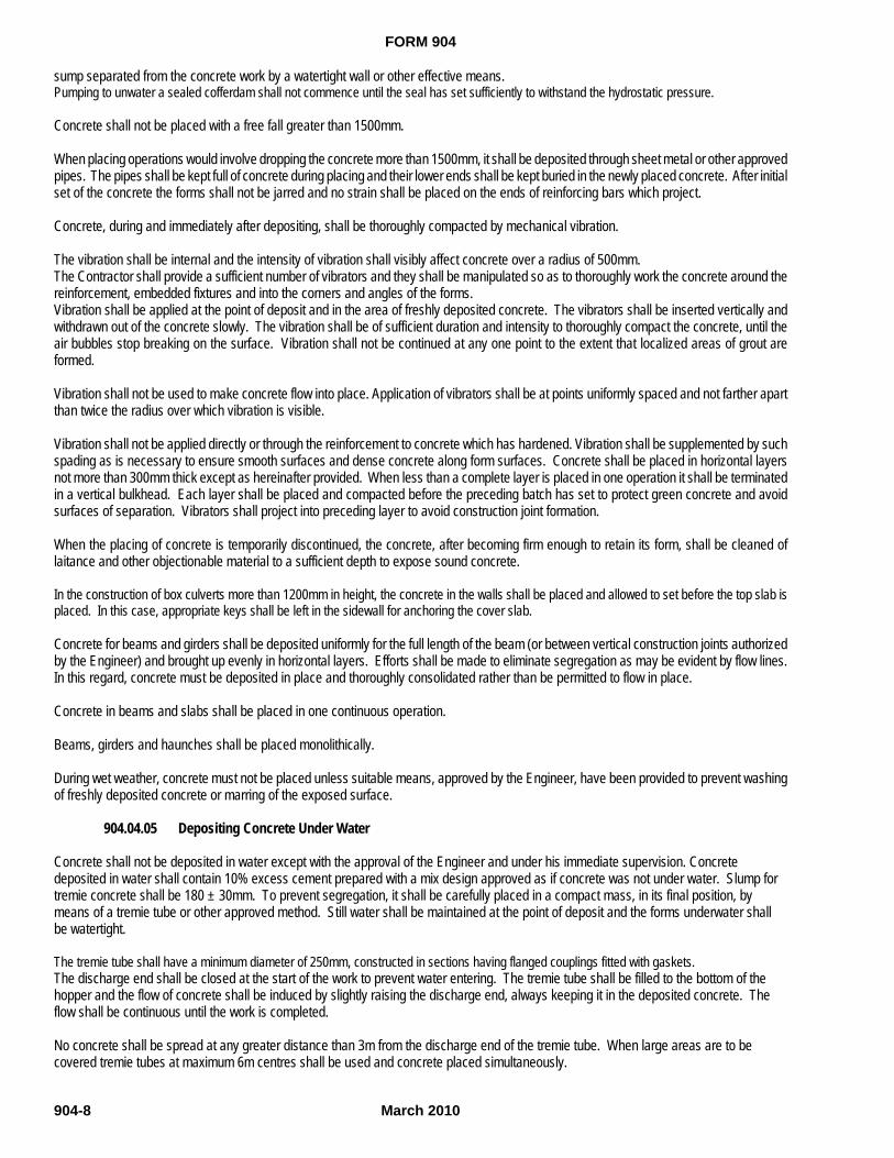
FORM 904
March 2010904-8
sump separated from the concrete work by a watertight wall or other effective means.Pumping to unwater a sealed cofferdam shall not commence until the seal has set sufficiently to withstand the hydrostatic pressure.
Concrete shall not be placed with a free fall greater than 1500mm.
When placing operations would involve dropping the concrete more than 1500mm, it shall be deposited through sheet metal or other approvedpipes. The pipes shall be kept full of concrete during placing and their lower ends shall be kept buried in the newly placed concrete. After initialset of the concrete the forms shall not be jarred and no strain shall be placed on the ends of reinforcing bars which project.
Concrete, during and immediately after depositing, shall be thoroughly compacted by mechanical vibration.
The vibration shall be internal and the intensity of vibration shall visibly affect concrete over a radius of 500mm.The Contractor shall provide a sufficient number of vibrators and they shall be manipulated so as to thoroughly work the concrete around thereinforcement, embedded fixtures and into the corners and angles of the forms.Vibration shall be applied at the point of deposit and in the area of freshly deposited concrete. The vibrators shall be inserted vertically andwithdrawn out of the concrete slowly. The vibration shall be of sufficient duration and intensity to thoroughly compact the concrete, until theair bubbles stop breaking on the surface. Vibration shall not be continued at any one point to the extent that localized areas of grout areformed.
Vibration shall not be used to make concrete flow into place. Application of vibrators shall be at points uniformly spaced and not farther apartthan twice the radius over which vibration is visible.
Vibration shall not be applied directly or through the reinforcement to concrete which has hardened. Vibration shall be supplemented by suchspading as is necessary to ensure smooth surfaces and dense concrete along form surfaces. Concrete shall be placed in horizontal layersnot more than 300mm thick except as hereinafter provided. When less than a complete layer is placed in one operation it shall be terminatedin a vertical bulkhead. Each layer shall be placed and compacted before the preceding batch has set to protect green concrete and avoidsurfaces of separation. Vibrators shall project into preceding layer to avoid construction joint formation.
When the placing of concrete is temporarily discontinued, the concrete, after becoming firm enough to retain its form, shall be cleaned oflaitance and other objectionable material to a sufficient depth to expose sound concrete.
In the construction of box culverts more than 1200mm in height, the concrete in the walls shall be placed and allowed to set before the top slab isplaced. In this case, appropriate keys shall be left in the sidewall for anchoring the cover slab.
Concrete for beams and girders shall be deposited uniformly for the full length of the beam (or between vertical construction joints authorizedby the Engineer) and brought up evenly in horizontal layers. Efforts shall be made to eliminate segregation as may be evident by flow lines.In this regard, concrete must be deposited in place and thoroughly consolidated rather than be permitted to flow in place.
Concrete in beams and slabs shall be placed in one continuous operation.
Beams, girders and haunches shall be placed monolithically.
During wet weather, concrete must not be placed unless suitable means, approved by the Engineer, have been provided to prevent washingof freshly deposited concrete or marring of the exposed surface.
904.04.05 Depositing Concrete Under Water
Concrete shall not be deposited in water except with the approval of the Engineer and under his immediate supervision. Concretedeposited in water shall contain 10% excess cement prepared with a mix design approved as if concrete was not under water. Slump fortremie concrete shall be 180 ± 30mm. To prevent segregation, it shall be carefully placed in a compact mass, in its final position, bymeans of a tremie tube or other approved method. Still water shall be maintained at the point of deposit and the forms underwater shallbe watertight.
The tremie tube shall have a minimum diameter of 250mm, constructed in sections having flanged couplings fitted with gaskets.The discharge end shall be closed at the start of the work to prevent water entering. The tremie tube shall be filled to the bottom of thehopper and the flow of concrete shall be induced by slightly raising the discharge end, always keeping it in the deposited concrete. Theflow shall be continuous until the work is completed.
No concrete shall be spread at any greater distance than 3m from the discharge end of the tremie tube. When large areas are to becovered tremie tubes at maximum 6m centres shall be used and concrete placed simultaneously.
FORM 904
March 2010 904-9
If the tremie operation is unavoidably interrupted below water level, the surface laitance shall be removed by jetting one day after placingand removed by pumping.
904.04.06 Mass Concrete
Mass concrete shall conform to the specifications outlined herein and be placed where indicated on the contract drawings as approved bythe Engineer. Where mass concrete exceeds 300 mm thickness at any footing edge, the design authority shall be contacted. Massconcrete shall be placed after all unwatering operations have been made effective in maintaining dry and controlled conditions asapproved by the Engineer.
904.04.07 Construction Joints
Construction joints in concrete shall be positioned at the location shown on the drawings or where otherwise approved by the Engineer.
The Contractor shall attach the appropriate horizontal and/or vertical strips to the face(s) of the formwork where all construction joints areplanned or occur for reasons beyond the Contractor's control. The concrete shall be worked such that the finished appearance will resemblenarrow, neat and straight horizontal and/or vertical line(s) at all construction and cold joints. Forms shall be kept tight throughout the entireconcrete placing operation.
At the bottom of curb - top of deck interface along the longitudinal sides of all decks, construction joints shall be neat, straight and properlyformed as a 20 mm Vee groove and shall be straight and true to line and grade.
Where construction or cold joints are planned or occur for reasons beyond the Contractor's control, the concrete interface shall be rough, cleanand free of laitance, with a full roughness amplitude of 6 mm or more. One exception to this would be at prestress steel box out locations, seeSection 906, "Prestressed Concrete Members".
Prior to butting the new concrete against previously hardened concrete the joint face shall be cleaned of all debris and dirt.In addition, the surface film of laitance and mortar shall be removed from the joint face to present a clean sound concrete face that has theaggregate particles exposed.
904.04.08 Contraction Joints
A contraction joint is a control joint to control volume change mainly (shrinkage). Bonding of the new and existing concrete is not required butprovisions to make the joint watertight are necessary.
Joints in concrete members shall be formed in location as shown on the plans.
Contraction joints shall extend to a depth equal to one-quarter of the member thickness. As soon as feasible the joint shall be thoroughlyflushed out with compressed air and an approved flexible joint filler compound utilized to fill the joint. The joint filler compound shall be flexibleover the extreme temperature conditions in the local area and must be approved by the Engineer.
904.04.09 Concrete Beam Seats and Bearing Surfaces
Concrete beam seats shall be magnesium floated to a level plane varying not more than 2mm from a straight edge placed in any directionacross the area. The finished level plane shall not vary more than 3mm from the elevation given by the Engineer in the field.
Concrete surfaces which are used as bearing surfaces are to be finished in accordance with the bearing manufacturer's recommendations.
904.04.10 Tolerances
All tolerances shall conform to Clause 10 "Tolerances" of CSA Standard CAN/CSA-A23.1-M.
904.04.11 Confilm
Immediately after the straight edge requirements have been met for the deck and curb concrete and the broom finish applied, the fresh concreteshall be coated with an evaporation retardant "Confilm" to preclude rapid evaporation of the bleed water. When all bleed water is gone, theconcrete shall be cured as per Section 904.05, "Curing". The supply and application of "Confilm" is deemed incidental to the placement of the
FORM 904
March 2010904-10
deck concrete and as such, no separate payment will be made by the Department.
904.04.12 Caulking of Joints
Caulking shall be applied to all control and expansion joint locations.The caulking or sealant and the substrate material must have a temperature greater than 5o C . Under no circumstances should sealant beapplied to any surface which contains moisture, condensation or frost. Joint surfaces are to be clean, dry and free of foreign matter beforeapplication of primer and sealant.
The work shall be performed by an approved caulking applicator. Otherwise, the contractor must designate a person for the caulking operationand that person should receive training acceptable to the Manufacturer and Engineer.
The Contractor shall supply a written guarantee of all workmanship and materials for a period of two (2) years following the date of finalcompletion.
Sealant shall be a three component Type 1-Dymeric (epoxidized polyurethane terpolymer) sealant as manufactured by Tremco (Canada)Limited or an approved equal, selected to most closely match the concrete colour. Primers are to be those specified by Tremco (Canada)Limited, specifically Primer#1 or an approved equal. Joint backing shall be a closed-cell non gaseous backer rod, such as Softrod specified byTremco (Canada) Limited or an approved equal.
All work shall be in strict accordance with the Manufacturer’s recommendations.
Payment shall be considered incidental to the works associated with concrete work pay items.
904.05 CURING
904.05.01 Fog Misting of Bridge Decks
Prior to the commencement of curing operations a fog mist shall be applied to bridge decks. Misting shall be conducted through the use ofa pressure washer capable of sustaining a minimum 14 MPa pressure. A continuous fog mist shall commence immediately behind thescreeding operation until concrete has hardened sufficiently to permit covering with burlap. The fog mist will maintain a high relative humidityabove the concrete and prevent surface drying prior to curing operations. Water shall not be allowed to drip, flow or puddle on the concretesurface during fog misting at any time before concrete has reached final set.
PAYMENT
Payment shall be considered incidental to the placement of Concrete in Superstructures.
904.05.02 Moist Curing
Proper curing will be considered 15% of the associated unit price bid for concrete payment purposes.
Concrete shall be continuously kept in a damp moist condition for at least seven days after placing and the temperature of the concrete shallnot be less than 10oC, during this period. If ambient temperatures are at or anticipated to be:
(a) Greater than 25oC, then the provision of Section 904.06, "Hot Weather Concreting", shall be followed.
(b) Less than 5oC, then the provision of Section 904.07, "Cold Weather Concreting", shall be followed.
Curing shall be applied to all surfaces.
Curing shall take place as soon as possible after the finishing operation without damaging the surface.
Concrete in the deck portion of all superstructure concrete, including barriers, approach slabs, expansion joint dams, end blocks, curbs andsidewalks must be cured by means of burlap and water.
All burlap must be pre-soaked by immersing it in water for a period of at least 24 hours immediately prior to placing. Two layers of burlap mustbe applied to the surface of the concrete. Strips must overlap by 150 mm and must be held in place without marring the surface of the concrete.

FORM 904
March 2010 904-11
The bridge decks burlap must be applied immediately after finishing of the concrete surface within 2 meters to 4 meters of the pan or screedof the finishing machine.
Curing with burlap and water must be maintained for a minimum period of 7 days. The burlap must be maintained in a continuously wetcondition throughout the curing period by means of a soaker hose. The burlap must be covered with a layer of moisture vapour barrier within12 hours of placing the concrete, in a manner which will prevent deformation of the surface of the concrete.
Air flow in the space between the moisture vapour barrier and the burlap must be prevented.
Regardless of ambient temperature, moist curing with burlap and water must be provided at all times. During cold weather, burlap must beprevented from freezing.
In addition to the burlap and water method as described above certain other concretes may be cured by either:
(a) Continuous Steam Curing
Continuous steam shall not exceed 80/C and shall follow CSA Standard CAN-A23-4 Precast Concrete-Materials and Construction.
(b) Curing with Filter Fabric and Water
One layer of filter fabric shall be laid on the surface of the concrete. Sheets or strips of filter fabric shall overlap by a minimum of 150 mm andshall be held down, as required, against displacement by wind, etc. The fabric shall be kept wet at all times. Filter fabric shall conform toSection 904.02.09, “Filter Fabric”. Filter fabric or non-woven geotextile may be used for curing on flat horizontal surfaces but not on verticalsurfaces. Vertical surfaces, i.e. abutments shall be cured using two saturated layers of burlap only.
904.05.03 Air Drying
Under normal circumstances curing time required for deck concrete is moist curing for seven (7) days in accordance with this specification anda further thirty (30) days for air drying. Also, the specified design strength must be obtained. Until the above conditions are satisfied, theapplication of waterproofing and the opening of the bridge to traffic will not be permitted.
It is not practical to achieve this, the above curing times may be reduced only at the discretion of the Engineer but in no case will the applicationof waterproofing and opening of the bridge to traffic be permitted until seven (7) days of wet curing and an additional seven (7) days of air dryinghave elapsed.
904.05.04 Plastic Shrinkage
Where excessive plastic shrinkage may occur, e.g. in a large expanse of concrete such as a bridge deck, more than one method of curing maybe required.
If shrinkage cracks occur the Contractor shall grout any cracks and repair by an approved method at his own expense.
All methods and materials employed in concrete curing must be approved by the Engineer.
904.05.05 Liquid Membrane Curing
At the discretion of the Engineer, liquid membrane curing compounds meeting the requirements of Clause 904.02.11, may be used in placeof moist curing on pier columns only. Liquid membrane curing shall not be permitted on other areas including bridge decks.
904.06 HOT WEATHER CONCRETING
When the air temperature is at 25oC or greater or is expected to rise to this limit, according to meteorological forecasts, then special measuresshall be taken by the Contractor to protect the concrete. Surface moisture evaporation must not exceed 0.75kg/m2/hr.
Concrete placed in the forms shall be maintained at or below 27oC and the Contractor shall obtain from the Engineer approval for his measuresto ensure this.
Curing shall be by moisture and with the exception of pier columns as per Clause 904.05.02, curing compounds will not be permitted.
904.07 COLD WEATHER CONCRETING

FORM 904
March 2010904-12
904.07.01 GeneralWhen the air temperature is at or below +5oC or when, according to meteorological forecasts, it is likely to fall below this limit within the next24 hours, then the Contractor shall take special precautions to protect the concrete placed. The Contractor shall obtain approval from theEngineer for this method of protection.Under normal circumstances no concrete for the superstructure (or approach slabs) shall be placed between November 1 and April 1.
The following table shall apply for determining degree of protection requested by the Engineer:
PROTECTIVECLASS PROTECTIVE MEASURE
OUTSIDE AIR TEMPERATURE FOR LEASTDIMENSION OF SECTION
LESS THAN 1M MORE THAN 1M
A SUITABLE HOUSING PLUS SUPPLEMENTARY HEAT OR ADEQUATE INSULATION BELOW 0OC BELOW -5OC
B SUITABLE COVERING PLUS ADEQUATE INSULATION 0OC TO 5OC 0OC TO -5OCC NORMAL CURING NO TEMPERATURE PROTECTION REQUIRED 5OC TO 25OC 5OC TO 20OC
Any concrete damaged by freezing or by inadequate protection or curing shall be removed and replaced by the Contractor at no cost to theDepartment.
For guidance on adequate insulation, refer to the Canadian Portland Cement Association publication "Design and Control of ConcreteMixtures", Chapter 11.
904.07.02 Placing
Concrete to be placed during cold weather shall be within the following temperature limits.
LEAST DIMENSION OF SECTION CONCRETE TEMPERATURE MINIMUM OC OC MAXIMUM
LESS THAN 0.3 M 10 27
0.3 M TO 1 M 10 27
1 TO 2 M 10 25
MORE THAN 2 M 5 20
This temperature can be obtained by heating the water or the aggregate or both; water and aggregate shall then be combined in the mixerfirst and the temperature of the mixture shall not exceed 38oC when the cement is added.
When the air temperature is below 0oC the water shall be heated to not greater than 66oC. The aggregates shall be uniformly heated in thestockpiles and/or bins by steam, either injected live or circulated in coils, or by using dry heat before the aggregates are placed in the mixer.Whatever system is used, it shall be designed to give uniform heating that will avoid local overheating which may be injurious to the materials.
No frozen lump of aggregate will be allowed in the concrete mix and shall be discarded before batching.
The use of salt, calcium chloride or other chemicals to lower the freezing point or accelerate the set is prohibited.
The ground, formwork, existing concrete and steel against which concrete is to be placed shall be free from ice and snow before the Engineerwill authorize placing to commence. The Contractor shall preheat the area in which the concrete is to be placed, with live steam or moist hotair, this shall also remove snow and ice and heat the contact material to prevent the formation of a cold joint.
Concrete shall not be placed on a frozen subgrade or against frozen ground. The Contractor shall protect excavations prepared for footings,etc., with covers prior to opening for placing concrete.
The concrete shall be placed rapidly and evenly, as near to its final position as possible to reduce the risk of segregation, flow lines and cold joints.
The concrete shall be covered, as quickly as possible after placing.
Surface moisture evaporation must be kept below 0.75 kg/m²/h. Concrete surfaces shall be protected by housing. Protective housing mustbe wind and weather tight and constructed of suitable materials on a substantial framework. The framework must be such as to keep thehousing at all points 300mm from the concrete and forms. The housing must have suitable openings to let the concrete be placed and these
FORM 904
March 2010 904-13
openings shall be so designed that they may be fully covered and closed as soon as the concrete is placed. The use of "roll back" sheetingor tarpaulins supported on stools is permitted on horizontal surfaces, such as a bridge deck provided the concrete is covered progressivelyas soon as placed. The housing must be so constructed as to allow a uniform circulation of heat to all parts of the work. This shall includethe underside of the bridge deck and beams unless the Engineer has authorized the protection of these areas by fully insulated formwork.
When mineral fibre is used as insulation, a layer of polyethylene having a minimum thickness of 6 mils shall be placed between the surfaceof the concrete or formwork and the insulation. This insulation is to be protected from moisture at all times.
904.07.03 Protecting Placed Concrete
For concrete to be placed between September 1 and April 30, the Contractor shall supply a steam jenny, fully operational and fully capableof adequately protecting all concrete to be placed, when specifically requested by the Engineer.
904.07.04 Heating the Protective Housing
The Contractor shall have available, tested and approved, adequate equipment for the heating of the protective housing. Heating will be usedto establish and maintain the required curing conditions.
For decks and curbs, sidewalks, parapet walks, the Contractor shall on the day prior to placing concrete, conduct a trial run to verify hisequipment, methods and workmanship to meet the specifications.
Live wet steam shall be used for heating unless other methods are permitted in writing by the Engineer. Hot air blowers and the like may beused to supplement the steam heating as long as fine water or steam spray into the stream of hot air is provided. The humidity as measuredby a wet and dry bulb thermometer shall at no time be less than 95% and the air temperature shall be not less than 13oC.
The use of salamanders, coke stoves, oil or gas burners and similar spot heaters which have an open flame and intense local heat areprohibited. In the event of any fire of the formwork or housing, the Engineer must be immediately notified.
The system of heating and positioning of steam outlets so as to give the most uniform distribution possible of the heat is subject to the approvalof the Engineer. The Contractor shall make suitable arrangements to stoke boilers outside normal working hours where required. A breakdownin heating is regarded as very serious especially in the early life of the concrete.
The concrete must be cured in a moist condition and its temperature shall be at least 10oC for seven days after the day of placing.
Protection shall be withdrawn in such a manner as not to introduce thermal shock stresses in the concrete.
The temperature of the concrete shall be gradually reduced at a rate not exceeding 17oC per day to that of the surrounding air. To achievethis in a heated housing, the heat shall be slowly reduced and then shut off and the whole housing allowed to cool to within 12oC of the airtemperature before the housing itself for the formwork is removed. Where work is to proceed within the same housing on the next stage ofthe work, the formwork may be removed as soon as the prescribed curing period is over. With fully insulated formwork, the forms themselvesmaybe slackened and some insulation removed if needed. The forms themselves shall not be removed until the temperature of the concretehas fallen to within 12oC of the outside air temperature.
904.08 SURFACE FINISHING
General
All concrete surfaces that will be visible on completion of the work shall conform to surface finish Class 2, with the exception of the deck, curbsand/or sidewalks which shall be Class 6 finish.
The Contractor shall take special care during the planning, forming, concrete placing, curing and stripping phases to ensure defect-freesurfaces. Should remedial measures be required, they shall be carried out by personnel expert in this aspect of concrete work. The surfacesshall be uniform in colour and texture when viewed from a distance of 15m and shall be attained as follows.
Class 2 Rubbed Finish
Immediately following the removal of forms, all fins and irregular projections shall be removed from all surfaces except from those which arenot to be exposed or are not to be waterproofed. On all surfaces, the cavities produced by form ties and all other holes, honeycombs spots,broken corners or edges and other defects shall be cut back to sound concrete and thoroughly cleaned. No feather edging is permissible.
FORM 904
March 2010904-14
If reinforcing steel is exposed, concrete shall be cut back for at least 50mm around the reinforcement.
After having been kept saturated with water for a period of not less than three hours, the cavities shall be carefully pointed and trued with amortar of cement and fine aggregate mixed in the proportions used in the grade of the concrete being finished. Mortar used in pointing shallbe not more than one hour old. The mortar patches shall be cured as specified under Section 904.05 "Concrete Curing". No mortar shall beplaced when the air temperature is forecasted to fall below 5oC within 24 hours. All construction and expansion joints in the completed workshall be left carefully tooled and free of all mortar and concrete. The joint filler shall be left exposed for its full length with clean and true edges.The resulting surfaces shall be true and uniform.
After removal of forms, the rubbing of concrete shall be started as soon as its condition will permit. However, before starting this work theconcrete shall be kept thoroughly saturated with water for a minimum period of three hours but sufficient time shall have elapsed before thewetting down to allow the mortar used in the pointing of rod holes and defects to thoroughly set. Surfaces to the finished shall be rubbed witha medium coarse carborundum stone, using a small amount of mortar on its face.
The mortar shall be composed of extra cement and fine sand mixed in proportions such as to match existing concrete verified by a test patch.Rubbing shall be continued until all form marks, projections and irregularities have been removed, all voids filled, and a uniform surface hasbeen obtained. The paste produced by this rubbing shall be left in place at this time.
After all concrete above the surface being treated has been cast, the final finish shall be obtained by rubbing with a fine carborundum stoneand water. This rubbing shall be continued until the entire surface is of a smooth texture and uniform colour. After the final rubbing iscompleted and the surface has dried, it shall be rubbed with burlap to remove loose powder and shall be left free from all unsound patches,paste, powder and objectionable marks.
Class 6 Floated Surface Finish
The provision of an approved self-propelled Bridge Deck Finishing Machine capable of striking off and providing the required surface finishis mandatory for all structures not covered by fill.
For new bridge decks and rehabilitated bridge decks where the total deck length is greater than fifteen (15.0) metres, the deck shall be finishedwith a GOMACO 450 bridge deck finishing machine with a vibrating screed and movable work bridge or approved equal.
For (a) decks less than fifteen (15.0) metres in length, (b) thin overlay strips wider than two (2.0) metres and (c) wharf decks, finishing shallbe achieved with a Razorback 12HD Air Operated Vibrating Allen Screed or approved equal.
All finishing equipment shall be utilized as outlined above, shall be equipped and operated in accordance with the manufacturer's literaturefor the particular concrete and work being performed.
For thin overlays less than two (2.0) metres wide, spotty or patchy deck repairs and corners of decks, a hand float finish is adequate.
A dry run of the finishing machine covering the entire area requiring finishing shall be made to insure the design deck thicknesses and profileswill be attained. The run shall be completed at least 24 hours prior to commencing the deck concrete placement.
The finishing machine must be accompanied by a working platform with two (2) qualified cement finishers assigned to the platform at all times.The Contractor shall submit letters to the Engineer for his approval stating the qualifications of the finisher. The Contractor shall supplysufficient quantities of double railing to support the finishing machine equal to the overall length of the deck. This will enable the Engineer tocheck the adjustment of the railing and the finishing machine prior to any concrete being placed.
Proper allowance shall be made for camber of pre-stressed channels or girders. Concrete placement shall be at a rate to provide satisfactoryprogress with the finishing machine or the cement finisher.
After the deck surface has been floated and any bleed water evaporated, but while the concrete is still plastic, the Contractor shall furnish anduse a 3m straight edge swung from handles half the width of the slab.
The straight edge shall be held in successive positions parallel to the road centre line and in contact with the surface and the whole area goneover from one side of the slab to the other as necessary. Advancement along the deck shall be in successive stages of not more than one-halfthe length of the straight edge. Any depressions found shall be immediately filled with freshly mixed concrete, stuck off, consolidated andrefinished. The straight edge testing and refloating shall continue until the entire surface is found to be free from observable departures fromthe straight edge and the slab has the required grade and contour, until there are no deviations of more than 8mm under the 3m straight edge.The concrete deck surface shall be given a broom finish when the concrete has hardened sufficiently. Exposed concrete bridge decks shallbe given a coarse broom finish. Treated or waterproofed bridge decks shall be given a fine broom finish. The broom shall be of an approved
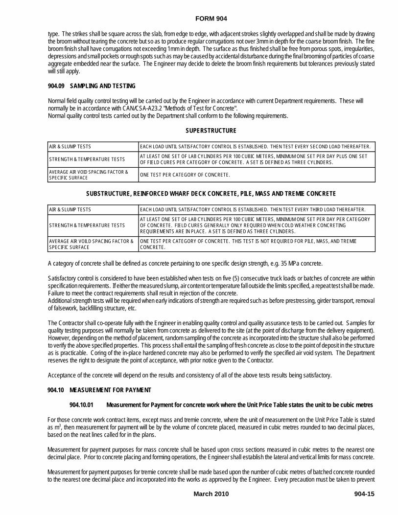
FORM 904
March 2010 904-15
type. The strikes shall be square across the slab, from edge to edge, with adjacent strokes slightly overlapped and shall be made by drawingthe broom without tearing the concrete but so as to produce regular corrugations not over 3mm in depth for the coarse broom finish. The finebroom finish shall have corrugations not exceeding 1mm in depth. The surface as thus finished shall be free from porous spots, irregularities,depressions and small pockets or rough spots such as may be caused by accidental disturbance during the final brooming of particles of coarseaggregate embedded near the surface. The Engineer may decide to delete the broom finish requirements but tolerances previously statedwill still apply.
904.09 SAMPLING AND TESTING
Normal field quality control testing will be carried out by the Engineer in accordance with current Department requirements. These willnormally be in accordance with CAN/CSA-A23.2 "Methods of Test for Concrete".Normal quality control tests carried out by the Department shall conform to the following requirements.
SUPERSTRUCTURE
AIR & SLUMP TESTS EACH LOAD UNTIL SATISFACTORY CONTROL IS ESTABLISHED. THEN TEST EVERY SECOND LOAD THEREAFTER.
STRENGTH & TEMPERATURE TESTS AT LEAST ONE SET OF LAB CYLINDERS PER 100 CUBIC METERS, MINIMUM ONE SET PER DAY PLUS ONE SETOF FIELD CURES PER CATEGORY OF CONCRETE. A SET IS DEFINED AS THREE CYLINDERS.
AVERAGE AIR VOID SPACING FACTOR &SPECIFIC SURFACE ONE TEST PER CATEGORY OF CONCRETE.
SUBSTRUCTURE, REINFORCED WHARF DECK CONCRETE, PILE, MASS AND TREMIE CONCRETE
AIR & SLUMP TESTS EACH LOAD UNTIL SATISFACTORY CONTROL IS ESTABLISHED. THEN TEST EVERY THIRD LOAD THEREAFTER.
STRENGTH & TEMPERATURE TESTSAT LEAST ONE SET OF LAB CYLINDERS PER 100 CUBIC METERS, MINIMUM ONE SET PER DAY PER CATEGORYOF CONCRETE. FIELD CURES GENERALLY ONLY REQUIRED WHEN COLD WEATHER CONCRETINGREQUIREMENTS ARE IN PLACE. A SET IS DEFINED AS THREE CYLINDERS.
AVERAGE AIR VOILD SPACING FACTOR &SPECIFIC SURFACE
ONE TEST PER CATEGORY OF CONCRETE. THIS TEST IS NOT REQUIRED FOR PILE, MASS, AND TREMIECONCRETE.
A category of concrete shall be defined as concrete pertaining to one specific design strength, e.g. 35 MPa concrete.
Satisfactory control is considered to have been established when tests on five (5) consecutive truck loads or batches of concrete are withinspecification requirements. If either the measured slump, air content or temperature fall outside the limits specified, a repeat test shall be made.Failure to meet the contract requirements shall result in rejection of the concrete.Additional strength tests will be required when early indications of strength are required such as before prestressing, girder transport, removalof falsework, backfilling structure, etc.
The Contractor shall co-operate fully with the Engineer in enabling quality control and quality assurance tests to be carried out. Samples forquality testing purposes will normally be taken from concrete as delivered to the site (at the point of discharge from the delivery equipment).However, depending on the method of placement, random sampling of the concrete as incorporated into the structure shall also be performedto verify the above specified properties. This process shall entail the sampling of fresh concrete as close to the point of deposit in the structureas is practicable. Coring of the in-place hardened concrete may also be performed to verify the specified air void system. The Departmentreserves the right to designate the point of acceptance, with prior notice given to the Contractor.
Acceptance of the concrete will depend on the results and consistency of all of the above tests results being satisfactory.
904.10 MEASUREMENT FOR PAYMENT
904.10.01 Measurement for Payment for concrete work where the Unit Price Table states the unit to be cubic metres
For those concrete work contract items, except mass and tremie concrete, where the unit of measurement on the Unit Price Table is statedas m3, then measurement for payment will be by the volume of concrete placed, measured in cubic metres rounded to two decimal places,based on the neat lines called for in the plans.
Measurement for payment purposes for mass concrete shall be based upon cross sections measured in cubic metres to the nearest onedecimal place. Prior to concrete placing and forming operations, the Engineer shall establish the lateral and vertical limits for mass concrete.
Measurement for payment purposes for tremie concrete shall be made based upon the number of cubic metres of batched concrete roundedto the nearest one decimal place and incorporated into the works as approved by the Engineer. Every precaution must be taken to prevent
FORM 904
March 2010904-16
waste of concrete, i.e. carelessness resulting in the escape of concrete from within the confines of the forms or inaccuracy in placing. In theevent of such occurrence(s) an estimate of the wastage will be made by the Engineer and an appropriate deduction from the batch quantitywill be made. All additional concrete required to be placed above the estimated quantity, must be approved by the Engineer.No deductions will be made from the volume of concrete for:
(1) Volume of reinforcement, prestressing steel or prestressing ducts.(2) Inserts of cross-sectional area of less than 0.1 m².
When it is specified that concrete is to be placed against undisturbed soil or set in rock, and where the excavation is made wider than the neatlines of the footings, the excess amount of concrete will not be measured for payment quantities.
Where the concrete footings are placed lower than that authorized by the Engineer, any excess amount of concrete will not be measured forpayment quantities.
Unless otherwise defined by the Contract Documents, the following will be the definitions for the structure and Unit Price Table:
Substructure concrete shall be that concrete used for slope paving, footings, abutments, back walls, bearing seats and pedestals, wing wallsand piers. Wingwall concrete shall be all concrete behind the back face of the abutment, i.e. including the cleat excluding curb (superstructure)concrete.
Where integral curbs and wing walls exist, a horizontal surface at the bottom of the curb including the bevelled portion thereof if any and thehorizontal surface at the top of the vertical portion of the wingwall shall constitute the dividing line between substructure and superstructureconcrete.
Retaining wall concrete shall be all concrete used in retaining walls and footings which are not cast integrally with the abutments.
Superstructure concrete will be all concrete used in columns, sidewalks, barriers, expansion joint dams, beams, diaphragms, decks, curbs,end blocks, including curbs and end blocks integral with the wing walls.
All concrete in rigid frames used in deck, curbs, barriers, sidewalks, end blocks, vertical or inclined legs and wing walls shall be classified assuperstructure concrete.
All concrete for rigid frame footings shall be classified as substructure concrete. All approach slab concrete shall be classified as superstructureconcrete.
Not included are AASHTO or CPCI girders, double tees, and any other superstructure work paid for separately.Not more than 90% of the units will be certified until such time as the surface finish meets the specifications and is completed to the satisfactionof the Engineer.
904.10.02 Measurement for Payment for concrete work where the Unit Price Table states the unit to be a unit other than cubic metres
For those concrete work contract items where the unit of measurement on the Unit Price Table is stated in some unit other than m3, then themeasurement for payment shall be in accordance with that stated in the appropriate specification for the item.
Not more than 90% of the units will be certified until such time as the surface finish meets the specifications and is completed to the satisfactionof the Engineer.
904.11 BASIS OF PAYMENT
904.11.01 Basis of Payment for concrete work where the Unit Price Table states the unit to be cubic metres
For those concrete work items where the unit of measurement in the Unit Price Table is stated as m3, then payment at the contract price shallbe full compensation for all materials, labour, equipment, plant and services necessary to complete the concrete work as outlined herein. Thisapplies to "Concrete in Substructure", "Concrete in Retaining Walls", "Concrete in Superstructures", "Reinforced Wharf Deck Concrete","Concrete in Rigid Frames", "Concrete in Approach Slabs", "Mass Concrete" and "Tremie Concrete".In particular no separate payment will be made for:
(a) supply of cement, aggregates and other materials, plant and equipment-use required for producing the concrete(b) Mix design, production, mixing, transportation, placing, consolidation, curing and quality control during production

FORM 904
March 2010 904-17
(c) Formwork and falsework(d) Precautions to be taken for hot weather(e) Precautions to be taken for cold weather (f) Provisions of shipping crates for concrete test specimens
No payment shall be made for any concrete required for normal testing procedures.Where excessive camber in girders is permitted by the Engineer, the extra concrete due to the camber in excess of the specifications will notbe paid for.
Concrete not placed in accordance with the provisions of Section 904.07, "Cold Weather Concreting", when the appropriate weather conditionsprevail will not be paid for unless and until it can be established to the satisfaction of the Engineer that there has been no harmful effect to theconcrete. The onus for establishing this will belong to the Contractor.
904.11.02 Basis of Payment for concrete work where the Unit Price Table states the unit to be a unit other thancubic metres
For those concrete work contract items where the unit of measurement in the Unit Price Table is stated in some unit other than m3, then thebasis of payment shall be in accordance with that stated in the appropriate specification for the item.
Concrete not placed in accordance with the provisions of Section 904.07, "Cold Weather Concreting", when the appropriate weather conditionsprevail will not be paid for unless and until it can be established to the satisfaction of the Engineer that there has been no harmful effect to theconcrete. The onus for establishing this will belong to the Contractor.
904.11.03 Concrete Acceptance and Reduced Payment Criteria on Concrete Located in New Structures
Concrete on a project of a certain class, as defined by its specified strength at 28 days, must have an average tested strength at 28 days equalto or greater than that specified for payment at the bid price.
Concrete of a certain class having an average strength of less than that specified will be accepted into the job at a reduced payment, providedthe difference between specified strength and tested strength is no greater than 5 MPa. If the average of tests in a particular predefined portionof concrete is less than that specified by more than 5 MPa then that concrete shall be rejected.
When concrete is rejected, those provisions outlined in CSA-A23.l-94 shall be followed to determine whether or not the concrete may remainin the work. Such work will be done at the Contractors cost. Notwithstanding the above, should the concrete remain in the work it will be subjectto a reduction, as outlined below, for having a strength less than that specified.
Concrete of a specific class and otherwise acceptable but having an average strength deficiency as tested of less than 5 MPa compared withthat specified, will be accepted but the bid price for all concrete in the predefined portion will be reduced according to the following procedure:
For concrete work where the Unit Price Table states the unit to be in cubic metres, the adjusted concrete price shall be calculated as follows:
$(Adjusted Concrete Unit Price) = Tested Strength / Specified Strength * $(Bid Concrete Unit Price)
Division of the structure into predefined portions will be done by the Engineer when the concrete placement sequence is outlined by theContractor at the pre-job meeting. A predefined portion shall generally be established as that concrete placed within one operation.
There will be no bonus payment under the contract when the average strength is in excess of the specified strength.
904.11.04 Concrete Acceptance and Reduced Payment Criteria on Concrete Located in Rehabilitated Structures
Concrete on a rehabilitation project in a certain repair class, as defined by its specified strength at 28 days, must have an average testedstrength at 28 days equal to or greater than that specified for payment at the bid price.
Concrete of a certain repair class having an average strength of less than that specified will be accepted into the job at a reduced payment,provided the difference between specified strength and tested strength is no greater than 5MPa. If the average of tests in a particularpredefined portion of concrete is less than that specified by more than 5M Pa then that concrete shall be rejected.
When concrete is rejected, those provisions outlined in CSA-A23.l-94 shall be followed to determine whether or not the concrete may remainin the work. Such work will be done at the Contractors cost. Notwithstanding the above, should the concrete remain in the work it will be subjectto a reduction, as outlined below, for having a strength less than that specified.

FORM 904
March 2010904-18
Concrete of a specific class of repair and otherwise acceptable but having an average strength deficiency as tested of less than 5 MPacompared with that specified, will be accepted but the bid price for all concrete in the predefined portion will be reduced according to thefollowing procedure:
For concrete work where the Unit Price Table states the unit to be square metres or cubic metres the adjusted price shall be calculated asfollows:
$(Adjusted Concrete Price)=(Tested Strength/Specified Strength) x $(Bid Concrete Unit Price)
Division of the structure into predefined portions will be done by the Engineer when the concrete placement sequence is outlined by theContractor at the pre-job meeting. A predefined portion shall generally be established as that concrete placed within one operation.
There will be no bonus payment under the contract when the average strength is in excess of the specified strength.
FORM 905
March 2010 905-1
GOVERNMENT OF NEWFOUNDLAND AND LABRADORDepartment of Transportation and WorksHighway Design Division
SECTION 905
CONCRETE REINFORCEMENT
INDEX
905.01 SCOPE905.02 MATERIAL905.03 FABRICATION, TRANSPORT AND STORAGE905.04 PLACING OF REINFORCING STEEL905.05 UNASSIGNED905.06 UNASSIGNED905.07 UNASSIGNED905.08 MEASUREMENT FOR PAYMENT
905.08.01 Measurement For Payment For Reinforcing Steel Used In Those Contract Items Where The Unit OfMeasurement Is Stated In Tonnes.
905.08.02 Measurement For Payment For Reinforcing Steel Used In Conjunction With Those Contract Items WhereReinforcement Is Considered Incidental To The Work.
905.09 BASIS OF PAYMENT
905.01 SCOPE
The scope of this section is to cover the supply, material, fabrication and placement of all reinforcing steel in concrete structures.
905.02 MATERIAL
The Contractor shall supply all the reinforcing steel to be incorporated in the work.
All reinforcing steel supplied shall be new and previously unused billet deformed bars having a yield point of 400 MPa and shall conform toCSA Standard CAN/CSA-A23.1-M90 and CSA Standard G30.18-M.
Where the contractor utilizes concrete blocks to support the reinforcing steel, the quality of the concrete blocks shall conform to Section 904,"Concrete Structures", and be of a quality similar to that being used in the member. The Contractor shall supply test results to verify the same.
Alternative reinforcing supports for reinforcing steel shall be continuous, plastic coated or stainless steel chairs. Richmond BB bolster shallbe utilized for the lower mat steel support and Richmond BBY beam bolster shall be utilized for the upper mat steel support. Equivalent typesof reinforcing steel supports may be approved by the Engineer. Reinforcing accessories such as chairs shall be corrosion resistant within25mm of all exposed surfaces.
Reinforcing steel shall be free of excessive rust and any reinforcing steel reduced in cross section area due to rust shall be rejected.
905.03 FABRICATION, TRANSPORT AND STORAGE
All properties including laps, splices, hooks and bends in reinforcement, etc. shall be as per CSA-S6-06; Canadian Highway Bridge DesignCode.
The Contractor shall submit six copies of a detailed reinforcing steel bar schedule to the Engineer. The schedule shall show all dimensionsand bending diagrams for all the reinforcing steel in accordance with ACI315-99 Manual of Standard Practise For Detailing Reinforced ConcreteStructures. The Contractor retains responsibility for correctly detailing reinforcement but the schedule must be approved for conformity withthe design. Fabrication of reinforcing steel should not proceed until approval of the schedule has been obtained.

FORM 905
March 2010905-2
The Contractor shall transport the reinforcing steel to the site and shall store it on racks or platforms with adequate identification.
All dirt, grease or other foreign materials shall be removed from the steel prior to the placement.
905.04 PLACING OF REINFORCING STEEL
Field bending shall not be carried out unless authorized by the Engineer and heat shall not be used for this purpose. Any bends developingcracks or splits shall be rejected.
No welding shall be carried out unless specifically authorized by the Engineer and if authorized, it shall be carried out in accordance with CSAStandard W186-M1990, Welding Of Reinforcing Bars.
Substitutions of different size bars must have the approval of the Engineer. Splicing at locations other than those specified on the drawingsmust be approved by the Engineer. All Contractor’s requests for splices other than those detailed on the contract drawings will be at theContractors’ expense.
Reinforcing steel shall be supported and firmly held in the required positions at all times. Only approved supports and chairs of strong durableand non-corrodible material shall be used.
Stainless steel, plastic, or corrosion resistant chairs, concrete blocks or other devices may be used if they satisfy the above requirements.
If reinforcement is in position for a considerable time prior to concrete being placed, then the reinforcing steel shall be reinspected and, wherenecessary, cleaned.
Bursting and spalling reinforcement shall be placed at nominal cover.
All reinforcement to be placed at nominal cover as per CSA-S6-06 unless otherwise stated on the contract drawings.
905.08 MEASUREMENT FOR PAYMENT
905.08.01 Measurement For Payment For Reinforcing Steel Used In Those Contract Items Where The Unit OfMeasurement Is Stated In Tonnes.
For those contract items where the unit of measurement on the Unit Price Table is stated in tonnes, then the total length of reinforcing steelused in the construction will be measured for payment. The payment quantity shall be determined by multiplying the lengths of reinforcing barsactually placed in the structure by its weight per metre according to the following table:
BAR DESIGNATION MASS WEIGHT KG/M
10M 0.785
15M 1.570
20M 2.355
25M 3.925
30M 5.495
35M 7.850
The total value will be converted to tonnes, calculated to three decimal places. Where substitution has occurred, the theoretical value will apply.Only that steel required by the contract drawings will be measured.
No allowance will be made for clips, wire, chairs, or other material used to fasten reinforcing steel in place. Measurement for payment purposesshall not be made for diaphragm inserts.
That reinforcing steel placed in AASHTO or CPCI girders and double tees shall not be included in the measurement for payment. Paymentfor this steel will be included with supply of prestressed girders.
Measurement for payment purposes will not be made for lap lengths if the bars are less than 15 metres long unless the lap is specificallyindicated on the contract drawings or it is not physically possible to use the 15 metre lengths.
FORM 905
March 2010 905-3
905.08.02 Measurement For Payment For Reinforcing Steel Used In Conjunction With Those Contract Items WhereReinforcement Is Considered Incidental To The Work.
Where reinforcement is considered incidental to the work, no reinforcing steel will be measured for payment purposes. Items where reinforcingsteel is considered incidental are catch basins, manholes, toe walls, head walls for culverts not greater than 1,500 mm diameter, footings forstairs, encasements for pipes not greater than 600 mm diameter, collars for pipes or other items as defined in the contract.
905.09 BASIS OF PAYMENT
Payment at the contract price per tonne for "Supply and Place Reinforcing Steel Except in Prestressed Girders", shall be full compensationfor supplying all materials at the work site, for storing, protecting and cleaning the reinforcing steel as required, for bending, cutting and weldingthe reinforcing steel, for placing the reinforcing steel in the work; for supporting the reinforcing steel during the placing, compacting and settingof concrete, and for such other work as may be required to complete the supply and placing of reinforcing steel.
The supply of reinforcing steel at the work site properly stored and protected and in proper condition for incorporation into the work shall bedeemed for progress payment purposes to constitute 75% of the work to be carried out under the Item "Supply And Place Reinforcing Steel,Except In Prestressed Girders".

FORM 906
March 2010 906-1
GOVERNMENT OF NEWFOUNDLAND AND LABRADORDepartment of Transportation and WorksHighway Design Division
SECTION 906
PRESTRESSED CONCRETE MEMBERS
INDEX
906.01 SCOPE906.02 GENERAL
906.02.01 Approvals And Casting906.02.02 Prestressing Method906.02.03 Inspection And Testing906.02.04 Member Top Flanges906.02.05 False work
906.03 MATERIALS906.03.01 Concrete906.03.02 Prestressing Steel906.03.03 Ducts906.03.04 Anchorage Assemblies906.03.05 Round Void Forms
906.04 DIMENSIONAL TOLERANCES906.05 PLACING CONCRETE, STRESSING & GROUTING TENDONS
906.05.01 Placing906.05.02 Prestressing Technician906.05.03 Stressing906.05.04 Bonding And Grouting
906.06 HANDLING AND INSTALLATION OF PRESTRESSED MEMBERS906.07 UNASSIGNED906.08 UNASSIGNED906.09 MEASUREMENT FOR PAYMENT
906.09.01 Prestressed Concrete Members906.09.01.01 Supply of Prestressing Steel And Accessories
906.09.02 Prestressed Concrete In Post- Tensioned Slab Superstructures906.09.02.01 Concrete906.09.02.02 Supply of Prestressing Steel And Accessories906.09.02.03 Concrete Surface Finish
906.10 BASIS OF PAYMENT906.10.01 Prestressed Concrete Members And Post-Tensioned Slab906.10.02 Supply of Prestressing Steel And Accessories

FORM 906
906-2 January 2008
906.10.03 Concrete Surface Finish906.10.04 Rejection
906.01 SCOPE
The Contractor shall furnish all labour, materials, equipment, plant and services specified, indicated or required to manufacture, transport, storeand install the prestressed concrete and/or prestressed steel components in accordance with the plans and specifications.
906.02 GENERAL
Post-tensioning in general, post-tensioning materials, grouting, preparations for post-tensioning, application and measurement of prestressingforce shall conform with CSA Standard CAN/CSA-A23.1-M09. Cast in place concrete or optionally precast at the site is normally covered byCSA Standard CAN/CSA-A23.1-M09. Precast concrete and pre-tensioning operations should conform to CSA Standard CAN3-A23.4-M latestedition.
Welding will not be permitted within 3.0 metres of any tendon without adequate protection of the prestressing steel from welding sparks. Underno circumstances shall prestressing steel be used to ground welding equipment.
906.02.01 Approvals and Casting
The Contractor shall clearly indicate in his bid his intention with regard to casting the prestressed concrete members on site or at an approvedplant. Prior to construction, the Contractor shall submit to the Engineer for approval the name of the plant from which it is intended to orderthe members. Only members supplied from an approved plant will be accepted.
906.02.02 Prestressing Method
The method of prestressing to be used shall be either pre-tensioning or post-tensioning as detailed on the drawings unless otherwise approved.
Prior to casting any concrete to be prestressed, the Contractor shall submit to the Engineer for approval six (6) complete sets of metric drawingsand one (1) set of metric design calculations. These details shall outline the method and sequence of stressing and shall include completespecifications and details of the prestressing steel and anchoring devices, e.g. anchorage blockout dimensions and angles, anchoring stresses,elongation calculations, type of enclosures, and all other data pertaining to the prestressing steel in the members, pressure grouting materialsand equipment, size and spacing of diaphragm and end block reinforcement, where applicable.
The prestress supplier shall determine through design or experience the prestress anchorage bearing plate/casting as well as the spiral steeldirectly behind and adjacent to the same.
906.02.03 Inspection And Testing
At all times the Engineer shall have the right to inspect and approve all methods, plant and materials involved. This shall include the right tomomentarily stop jacking in order to measure the elongation and jacking pressure from initial to final load on as many cables as deemedappropriate by the Engineer.
906.02.04 Member Top Flanges
Members whose top flanges become the bottom form for the deck slab shall have the flange designed to safely accommodate all temporaryconstruction loads.
906.02.05 False work
Sound, adjustable false work in accordance with Section 907, "Form work And Falsework", shall be required to compensate for any settlementsuch that the structure, particularly the soffit, is constructed true to line and grade. The prestressed concrete is not self supporting untilstressing, anchoring, grouting and proper curing have been carried out. Except as noted on the contract drawings and as outlined in theSpecifications, false work may be removed after these operations have been completed. The prestressing ducts, strands and anchorages mustbe accurately and rigidly fixed in position before any concrete is placed.
906.03 MATERIALS

FORM 906
906-3January 2008
906.03.01 Concrete
All concrete work shall conform to the requirements of the Section 904, "Concrete Structures", unless otherwise stated herein.
The minimum ultimate compressive strength of the concrete shall be as shown on the plans and at the time of tensioning shall be verified bythe Engineer from the results of the field cured test cylinders.
Care must be taken to ensure that the test cylinders are compacted and cured under conditions similar to the conditions acting on the concretein place. At least three specimens shall be tested from each batch prior to tensioning the cables and at least three specimens at 28 days.
No concrete shall be deposited in the forms until the placing of reinforcing steel, enclosures, anchorages and prestressing steel has beeninspected and approved by the Engineer.
An inspection and testing company may be appointed by the Engineer to inspect and control quality of materials. If so, separate payment willbe arranged for by the Department. The Contractor shall provide, without charge, all materials required for test purposes and give all necessaryco-operation.
906.03.02 Prestressing Steel
All prestressing steel shall be protected against damage, rust and other corrosion and shall be free of all dirt, oil, grease and other deleterioussubstances when finally grouted in the deck. Splicing of prestressing steel bars only shall be permitted to manufacturers' specifications.Splicing of strands or wire is not permitted.
All prestressing steel from each manufactured reel of wire, strand or mill heat of bar to be shipped to the site, shall be assigned an individuallot number and shall be tagged in such a manner that each such lot can be accurately identified at the job site. All unidentified prestressingsteel received at the site will be rejected.
The Contractor shall furnish one sample, 1500 mm long from each manufactured reel of wire, strand or mill heat of bar prestressing steel fortesting purposes. The Engineer will select the samples of prestressing steel from the job site and all materials for testing shall be furnishedby the Contractor at his own expense.
The Contractor shall have no claim for additional compensation in the event his work is delayed awaiting approval of the materials.
The approval of any material by the Engineer shall not preclude subsequent rejection if the material is damaged in transit or later damagedor found to be defective. Storage of the material on site shall be in accordance with Prestressing steel shall be high tensile strength 7-wirestrand or bar as shown on the contract drawings, fabricated, sampled and tested in accordance with the requirements of ASTM A 416/A 416M-02 and ASTM A 421/A 421M-02 and to the satisfaction of the Engineer. Longer term storage of prestress steel and components, i.e. storageover the winter, shall be in accordance with ASTM A 416/A 416M-02 and ASTM A 421/A 421M-02 and the environment shall not be wet, humidor subject to the accumulation of moisture.
Two copies of the mill certificate and two copies of the stress-strain curves representative of the actual lots to be used shall be submitted tothe Engineer with samples.
Prestressing steel shall be high tensile strength 7-wire strand or bar as shown on the contract drawings, fabricated, sampled and tested inaccordance with the requirements of 416/A 416M-02 and A 421/A 421M-02.
Tendons shall consist of parallel wires or strands composed of the required number of high tensile, cold-drawn, low-relaxation (stabilized)strands. Positive end anchorage shall be provided on each end of the tendon after threading through the terminal hardware. The tendon shallbe enclosed in mortar-tight flexible metal conduit.
The pre-assembled connection between the conduit and the end bearing assemblies shall be adequate to ensure a mortar tight enclosure fromterminal to terminal. The anchor shall provide for grout passage into the tendon. The supplier of the tendons shall furnish grout fittings forattachment to the terminal hardware.
High tensile strength steel shall be from steel made by the open hearth, electric furnace or basic oxygen process to produce the desired hightensile strength. Strand shall have a nominal diameter of 15.24 mm, minimum ultimate tensile strength of 260.6 kN and a nominal end areaof 140.0 mm2 per strand, or as otherwise indicated on the contract drawings.
Steel grade shall be 1860 MPa unless otherwise specified on the contract drawings.
FORM 906
906-4 January 2008
Oil tempered steel shall not be employed for use in prestressed concrete construction.
The complete stress-strain curve for the steel shall be obtained for each heat or lot of steel used in the entire project and shall be used as datafor stressing of the steel of that particular heat or lot. Care shall be taken that the steel so defined is correctly identified.
The Contractor shall furnish one entire tendon complete with anchorages, one complete coupling device and all hardware for testing andevaluation purposes, if so indicated in the Contract Documents. If the tendon and/or associated hardware has not been previously used inNewfoundland, the Engineer may request a sample for evaluation and testing purposes. Any components which in the opinion of the Engineer,fall below the quality of the sample provided shall not be used in the works.
906.03.03 Ducts
Ducts for prestressing steel shall be made of approved bright metal rigid or semi-rigid corrugated steel tubing with mechanical joint connectionsof the diameter as shown on the drawings. Rigid ducts shall have a minimum wall thickness of 0.60 mm and be capable of being bent to aminimum inside radius of 9 metres without distress. Semi-rigid ducts shall have a minimum wall thickness of 0.25 mm and be capable of beingbent to a minimum inside radius of 3.5 metres without distress. The wobble friction coefficient (k) shall not exceed 0.0023 per metre and 0.0033per metre for rigid and semi-rigid ducts respectively. The curvature friction coefficient (µ) shall not exceed 0.20 for both duct types. Rigid ductsshall be used for longitudinal tendons and semi-rigid ducts used for transverse tendons unless otherwise specified in the contract documents.
Ducts shall be watertight and of sufficient strength to withstand all forces imposed upon them during placing of concrete without denting,sagging or leaking. All ducts and anchorage assemblies shall be provided with any necessary air vents and pipes for the injection of grout afterprestressing. Grouting ducts and vents shall be located at all high points and at both ends of all longitudinal tendons. For transverse tendons,grouting ducts and vents shall be located at both ends of all tendons and at all high points when the vertical distance between the lowest andhighest point in the duct exceeds 400 mm.
906.03.04 Anchorage Assemblies
The anchorages shall be of an approved type as indicated on the contract drawings for the size of tendons shown on the drawings completewith all required spiral reinforcement.
Anchoring hardware shall meet the minimum requirements set forth in CAN/CSA-A23.1-M09. Moreover, the anchorage components, i.e. thebearing plate, wedges, anchor head and/or casting to develop at least 100% of the ultimate tendon capacity but the prestressing steel asanchored is permitted to fail at 95% of the ultimate tendon capacity.
All reinforcement, duct work, cones and/or anchorages shall be fastened firmly so that no movement can occur when concrete is placed.Anchorages shall be held tight to the end forms so that no laitance can leak down the face of the cone or bearing plates. Enclosures shall beprotected against the entrance of foreign matter prior to grouting particularly in cold weather.
The anchorages shall be placed in the position shown on the contract drawings. The axis of the anchorage must coincide with the axis of thecable passing through it. Details of end anchorages, i.e. block out dimensions and angles shall be determined by the prestress supplier incoordination with the Engineer.
906.03.05 Round Void Forms
When required the type of round void form used shall be in accordance with the following table:
OUTSIDE DIAMETER OF VOID TYPE OF ROUND VOID FORM
OVER 930 MM 1.2 MM CORRUGATED METAL PIPE
630 MM - 930 MM 1.0 MM CORRUGATED METAL PIPE
UNDER 630 MM 1.0 MM CORRUGATED METAL PIPE OR SONOVOID TUBES, TYPE D, 100% DUROBOARD OR APPROVED EQUAL
Metal void forms shall have outside diameter (top of corrugations to top of corrugation) equal to the diameter of the voids shown on thedrawings.
Void tubes made of fibrous material shall be protected against damage during storage and handling and shall be protected from moisture andwater at all times. Adequate ventilation shall be provided to prevent damage due to humidity. The void tubes shall not be stored on the sitefor more than seven days before installation.
The void tubes shall be designed to withstand the forces imposed on them during concreting and until the concrete has set up, without

FORM 906
906-5January 2008
deformation such as bulging, sagging or collapse.
Damaged tubes shall not be used.
All void tubes must be accurately placed and rigidly fixed in position before any concrete is placed. The Contractor shall pay particular attentionto the buoyancy of the voids and adequate measures shall be taken to counteract the same. No concrete shall be placed until the installationof the tubes has been inspected and approved by the Engineer.
906.04 DIMENSIONAL TOLERANCES
The following dimensional tolerances will be allowed:
LENGTH = ± 10 MM
CROSS SECTION = ± 3 MM FROM EACH DIM. (NOT CUMULATIVE)
ALIGNMENT = ± 3 MM MAX. IN ANY 3 M LENGTH
CAMBER DIFERENTIAL BETWEEEN ADJACENT PRESTRESSED MEMBERS = 20 MM MAX.
In addition, camber in the prestressed members immediately after stressing or de-tensioning shall not vary more than 50% of the calculatedvalue. Camber due to member dead load only, at the time of placing the deck slab, shall not be more than 20 mm greater than the initialcamber.
Deck slab surface under full dead load shall be to the grades indicated on the drawings. The deck slab thickness shall be constant betweenthe top flanges of adjacent members. In order to meet these criteria the Contractor shall haunch the deck slab over the member or protrudethe member a maximum of 20 mm into the deck slab or both, as indicated on the drawings.
For prestressed slab superstructures the deck slab surface and soffit shall be to the grades indicated on the drawings immediately afterstressing, unless otherwise indicated in the contract documents.
906.05 PLACING CONCRETE, STRESSING AND GROUTING TENDONS
The minimum concrete strength at stressing shall be 30 MPa unless otherwise specified on the contract drawings.
906.05.01 Placing
Concrete must not be deposited in the forms until the Engineer has inspected the placing of the reinforcement, ducts, anchorages, prestressingsteel and has given his approval thereof.
Bar reinforcing steel and prestressing steel shall be placed accurately at the locations shown on the drawings or approved by the Engineer.The distance from the forms shall be maintained by plastic bar chairs, spacers, hangers or hold down devices. Within a 5.0 metre longitudinaldistance from support locations i.e. piers and abutments, a tolerance of + 6mm will be permitted in the placing of prestressing ducts. At all otherlocations a tolerance of + 12mm will be permitted.
Post-tensioning ducts must be held securely at intervals of 500 mm or less against vertical or horizontal displacement from true alignmentduring the placing of concrete.
Holes shall be provided for anchor dowels and for diaphragm dowels which pass through the member, openings for connection rods, recessesfor grout and holes for railing bolts in the members shall be provided in accordance with the details shown on the drawings.
Where diaphragm dowels do not pass through the member, the dowels shall be anchored in the member by embedment in the concrete orby means of approved threaded inserts.
Where openings for diaphragm dowels are provided, these dowels shall be grouted in place after the installation of the member in the structure.
Where continuous prestressed concrete slab type construction is required, the deck shall be cast in one continuous concrete placing operationcommencing at the lower end of the structure.
The concrete must be vibrated internally or externally or both as required to consolidate the concrete. The vibrating shall be done with careand in such a manner that reinforcing steel, ducts and prestressing steel will not be displaced. Vibrators shall operate at a minimum
FORM 906
906-6 January 2008
frequency of 160 Hz for the internal type and 60 Hz for the external type.
The Contractor shall pay particular attention to concrete placement details, external vibration shall be used when casting CPCI girders.
All curing methods shall be subject to the Engineer's approval. Curing shall be in accordance with Section 904.05, "Curing", of theSpecifications Book.
906.05.02 Prestressing Technician
The Contractor shall provide at his own expense a technician familiar with the type of prestressing involved, approved by the Engineer, tosupervise all prestressing work. This technician shall be present at the completion of the steel installation and just prior to concretingoperations, at stressing and grouting operations.
The prestressing supplier shall formally certify in writing that the stressing technician being employed on the works has sufficient knowledgeand experience to undertake and successfully complete the prestressing, grouting and associated work.
906.05.03 Stressing
All prestressing steel shall be stressed by means of hydraulic jacks which shall be equipped with accurately calibrated hydraulic pressuregauges, damped from vibration, with a dial not less than 150 mm in diameter, to permit the stress to be computed at any time. A certifiedcalibration curve shall accompany each jack, showing the relationship between gauge readings and stress in the ram for both ascending anddescending movements of the ram. In general monostrand jacks shall not be used for stressing multi-strand tendons unless specificallyapproved by the Designer. A monostrand jack shall be present on site during stressing operations or be available to the Contractor within a48 hour delivery period should the need arise
A load cell attached to the jack will be accepted, as an alternative to the above, as a means of obtaining the force in the tendon provided theaccuracy of the load cell is attested to by an authority acceptable to the Engineer.
The stressing operation shall be conducted in a manner recommended by the manufacturer of prestressing material and only in the presenceof the Engineer or designated representative.
The supervisor in charge of the tensioning shall be provided with the required extension of the tendons and the jack pressure. The extensionshall be carried out at an even rate, jack pressure and extension shall coincide with the required extension and pressure at the time ofanchoring, due allowance being made for anchorage slippage at both ends of the tendons. The permissible variation in specified prestressshall not be more than 95% to 100% of the theoretical jacking force or pressure for both longitudinal and transverse tendons. Moreover, thepermissible variation in specified elongation shall not be more than ± 5% of the theoretical elongation for longitudinal tendons. For transversetendons the permissible variation in specified elongation shall not be more than ± 5% of the theoretical elongation or ± 10 mm whichever isgreater.
The stress in the tendons shall be measured by means of the extension of the tendons and shall be continuously checked by means of thepressure gauge on the jack. The accuracy of the jack pressure gauge shall be checked periodically. The zero error in the jack pressure shallbe determined by plotting a few straight pressure readings against jack extension and extending the straight line back to determine the zerointercept.
The stressing shall be carried out as shown on the contract drawings. The tensioning shall not be commenced until the tests on the concretecylinders, manufactured and cured under the same conditions as the prestressed member, indicate that the concrete of the member hasattained the required compressive strength as shown on the contract drawings.
After the concrete is placed, no tensioning will be permitted until it is demonstrated, to the satisfaction of the Engineer, that the prestressingsteel is free and unbounded in the enclosure.
Any tendon in which the accuracy of the extension is doubted shall be de-stressed and restressed in the presence of the Engineer.
Records of elongation, calibrated jack force readings and slip shall be kept by the Engineer. Until such approval is obtained in writing, notendons shall be grouted.
The prestressed steel shall be anchored at a stress that will result in the ultimate retention of working forces or stresses of not less than thoseshown on the plans, but in no case shall the steel be tensioned above 80% of the ultimate strength. Losses in stress due to creep, plastic flow,elastic flow and shrinkage of concrete plus creep of steel and sequence stressing, shall be computed in accordance with CSA-S6-06 latestedition.

FORM 906
906-7January 2008
Prestressed strands which have been stressed and meet project criteria shall be cut off with a saw; a torch is not acceptable. The Contractor
shall leave 25-50 mm of strand protruding beyond the visible end of the wedge.
906.05.04 Bonding And Grouting
The Contractor shall sandblast all concrete surfaces in anchorage boxout areas and fill the boxout with concrete of a quality similar to that usedin the member. For anchorages without the tendon end cap, anchorage recesses or boxouts are to be sandblasted and filled with concretebefore grouting operations commence.
All post-tensioned prestressing steel shall be bonded to the concrete by pressure grouting the ducts or openings. All stressing shall becompleted before grouting begins. All areas around post-tensioned cables, strands, tendons or rods shall be completely filled with high earlystrength non-shrink grout.
The grouting procedure shall be approved by the Engineer.
Generally this work shall be done as soon as the prestressing steel has been stressed and approved and in no case shall any tensionedprestressing steel be left ungrouted for more than seven (7) days after prestressing.
In the case of post-tensioned slabs which contain both longitudinal and transverse prestressing steel, the maximum time permitted betweenthe beginning of the stressing sequence and the grouting of the last cable shall not exceed two weeks.
Stressing and grouting sequences of longitudinal and transverse tendons shall be as outlined in the contract documents. The maximum timepermitted between the beginning of stressing and grouting of the last cable shall not exceed two weeks.
All ducts or openings shall be clean and free of all foreign materials that would impair bonding of the grout. Each duct or opening shall bethroughly blown out with compressed air immediately prior to grouting. Where it is found necessary, in the opinion of the Engineer, the ductor opening shall be flushed out with water, prior to use of compressed air. The concrete shall have a temperature of at least 5oC at the timeof grouting and shall be maintained at this temperature or higher for a period of at least 48 hours. If necessary this may include preheatingthe structure and maintaining protection for a period of three days after the grout is placed. The temperature of the grout at the time of injectionshall be not less than 16oC nor more than 27oC.
Grout shall have a maximum water : cement ratio of not more than 0.36, not contain any trace amounts of chlorides, contain at least 6% ofsilica fume by weight, contain an approved superplasticizer and an approved expansive agent. Masterflow 816 Cable and Anchor groutmanufactured by Master Builders Inc. and In-Pakt Standard SF grout manufactured by CC Chemicals are two grouts which meet the abovecriteria. Approved equivalent grouts as determined by the Engineer may also be utilized.
The grout mix design and representative samples shall be submitted for approval at least 14 days in advance of anticipated use. The mixdesign must be approved by the Engineer prior to grouting. The grout shall be mixed and placed as per the manufacturer's instructions andunder the supervision of the Engineer. The compressive strength of the grout shall be at least 40 MPa in four (4) days. Strength tests shallbe performed on 50 mm cubes, stored and tested in accordance with ASTM Specification C109.
The Contractor shall be responsible for all mix design and quality control of grout production and placing. Quality control and assurance ofthe grout from a testing viewpoint shall be provided by the Department.
When allowed to stand for 15 minutes, the grout shall not bleed or segregate. At the time of initial set, the grout shall exhibit an expansion of8% (± 2%) of its original volume.
Grouting equipment shall be capable of grouting to a pressure of at least 1.5 MPa with a 19 mm minimum inside diameter grout hose, maximumpressure 1.7 MPa.
Alternatively, the grouting equipment shall be specifically designed for the job and approved by the Engineer.
Grout shall be mixed in an approved mechanical mixer, that provides for straining and re-agitating the grout before it is used. Time betweenmixing and pumping the grout shall not exceed 40 minutes.
Retempering the grout will be prohibited.
FORM 906
906-8 January 2008
The grout shall completely fill the duct or opening and shall be allowed to flow continuously and freely for 5 seconds at the outlet end of theduct or opening. In case the continuity of grouting is interrupted, the duct or opening shall be immediately cleaned out. A dependable highpressure air and water supply shall be on hand during grouting.
After grout has set, all exposed vents and hoses, in finished concrete surfaces are to be removed 50mm from the finished surface. Theresulting void or cavity must have all debris removed and be throughly cleaned. The void or cavity should be filled with SET 45, manufacturedby Master Builders or an approved equal. The Contractor shall follow the Manufacturer’s recommendations and specifications in the mixingand placing of SET 45.
906.06 HANDLING AND INSTALLATION OF PRESTRESSED MEMBERS
At least seven (7) days before starting work, the Engineer shall be fully informed as to the method of handling, installation and the amount andkind of equipment proposed for use. The Contractor shall comply with the provisions of the Highway Traffic Act and make all necessaryarrangements with the authorities for permission to transport.
The Contractor shall exercise extreme care in handling, storing, moving and erecting precast prestressed concrete members to avoid twisting,racking or other distortion that would result in cracking or damage to the members. The Contractor shall handle, transport and erect precastprestressed members in an upright position and keep the points of support during lifting, storing, transportation and erection within 600 mmof the points of support in the final structure. The Contractor shall not permit the reactions of the lifting devices to be inclined to the verticalat an angle greater than thirty degrees. Holes provided for lifting shall be filled with mortar when members have been placed.
The Contractor must decide upon the method by which he plans to lift the prestressed girders and submit design calculations signed andstamped by a Professional Engineer licensed to practice in the Province of Newfoundland.
The Contractor is responsible for the stability of the prestressed girders during placing and until the diaphragms are in place regardless of theloading conditions.
Prestressed concrete girders shall not be moved or transported until the grout has attained 30 MPa. False work shall not be removed fromcontinuous prestressed concrete structures until the grout has attained 30 MPa. Loads in addition to member self-weight shall not be placedon the prestressed concrete members until the grout has attained 30 MPa. Grout samples shall be taken, field cured and tested to establishthe appropriate time to move or transport girders, remove false work or apply loads to prestressed concrete structures. Grout samples shallalso be obtained and tested for acceptance purposes.
906.09 MEASUREMENT FOR PAYMENT
906.09.01 Prestressed Concrete Members
The quantity of prestressed members supplied and erected for which payment shall be made shall be the total number of members requiredas shown on the plans.
906.09.01.01 Supply of Prestressing Steel and Accessories
Prestressing tendons including anchorages will be measured as a lump sum for the total number required by the contract. Payment for theSupply of Prestressing Steel and Accessories will not be made where the prestress steel and/or components are held in longer term storage,i.e. over the winter.
906.09.02 Prestressed Concrete In Post- Tensioned Slab Superstructures
906.09.02.01 Concrete
Measurement for payment will be by cubic metres of concrete placed based on neat lines shown on the plans. No deductions will be madefrom the volume of concrete for reinforcing or prestressing steel, anchorages or inserts. Deductions for any design voids will be made. Thequantity shall include the volume of concrete in curbs, sidewalks, medians, parapets, including those on the wingwalls or as otherwise shownon the plans.
906.09.02.02 Supply of Prestressing Steel and Accessories
The quantity of prestressing tendons including anchorages for which payment shall be made shall be the total number of tendons required asshown on the plans. This will be considered as a lump sum and includes both transverse and longitudinal tendons as indicated on the contractdrawings.
FORM 906
906-9January 2008
906.09.02.03 Concrete Surface Finish
Measurement for payment for surface finish shall be in accordance with Section 904, "Concrete Structures".
906.10 BASIS OF PAYMENT
906.10.01 Prestressed Concrete Members and Post-Tensioned Slabs
Payment at the contract price shall be full compensation for all materials, labour, equipment, plant and services necessary to complete the
prestressed concrete work in accordance with the plans and as described herein.
In particular, no separate payment will be made for:
a) Supply of cement, aggregates and other materials, plant or equipment for producing the concrete.b) Supply and placement of grout.c) Form work and false work.d) Supply and installation of void tubes including all drain tubes, air vents, bracing, non-corrosive chair supports, splices and
end closures.e) Sandblasting the construction joints.f) Supply and apply approved bonding adhesive.g) Supply and installation for reinforcing steel except that in post-tensioned slabs.h) Transporting and storing prestressed concrete members.i) Any post construction jacking of the superstructure.
Payment for post-tensioned slab concrete will be under Section 904, "Concrete In Superstructures".
Payment for prestressed concrete members, such as AASHTO or CPCI Girders and double tees, will be under "Prestressed Girders" (a)supplied, (b) installed as appropriate.
906.10.02 Supply of Prestressing Steel and Accessories
Payment at the contract unit price for "Supply Of Prestressing Steel And Accessories" shall be full compensation for all materials, labour,services, plant and equipment necessary for the supply, delivery, installation and stressing of the tendons including all anchorages, burstingand spalling or end block steel and grouting as required in accordance with the contract drawings and this specification.
For post-tensioned slab structures, the materials, fabrication and placing, cost of bursting and spalling or end block steel shall be paid for underSection 905, "Concrete Reinforcement".
906.10.03 Concrete Surface Finish
Payment for concrete surface finish shall be in accordance with Section 904, "Concrete Structures".
906.10.04 Rejection
Excessive honeycombing, distortion, warping, cracking, improper grouting or other evidence of inferior workmanship or failure to meet therequirements of these specifications shall be cause for rejection of any member.
Minor surface cavities or irregularities which are satisfactorily repaired shall not constitute cause for rejection. Repairs shall not be made untilthe Engineer has inspected the extent of the irregularities and has determined whether or not the concrete will be rejected.
Final acceptance of members will not be made until they have been installed in the structure. Members that have been tentatively acceptedat the manufacturing plant but are damaged in transit shall be replaced by the Contractor at his own expense.
Erection by a non approved method may be cause for rejection.

FORM 907
Macrh 2010 907-1
GOVERNMENT OF NEWFOUNDLAND AND LABRADORDepartment of Transportation and WorksHighway Design Division
SECTION 907
FORMWORK AND FALSEWORK
INDEX
907.01 SCOPE907.02 SUBMISSION OF SHOP DRAWINGS907.03 DESIGN
907.03.01 General907.03.02 Stresses907.03.03 Loadings and Deflections907.03.04 Void Tubes And Inside Forms
907.04 MATERIALS907.05 FORMWORK CONSTRUCTION
907.05.02 Supply and Installation of Form Liner907.06 FALSEWORK CONSTRUCTION907.07 REMOVAL OF FORMWORK AND FALSEWORK907.08 HANDRAIL END BLOCK RECESSES907.09 BASIS OF PAYMENT
907.01 SCOPE
The scope of this section is to cover the design and construction of formwork and falsework used in connection with the work.
Falsework is defined as structural supports, load carrying members and the necessary bracing required for the support of temporary loadsduring construction.
Formwork is defined as the mould into which concrete is placed.
Other definitions are as per CSA Standard S269.1-1975, Falsework For Construction Purposes.
907.02 SUBMISSION OF SHOP DRAWINGS
The Contractor shall prepare and submit to the Engineer for approval copies of detailed shop drawings and calculations for all falsework inthe project. Falsework drawings shall be signed and sealed by a licensed member of the Association of Professional Engineers ofNewfoundland.
Six copies of drawings will be required and four weeks will be required for approval. No falsework shall be placed prior to the design beingapproved by the Engineer.
Approval of these drawings will be for conformance with the design and shall not relieve the Contractor of any responsibility for the safe designand installation of the falsework.
Shop drawings for formwork shall be submitted if required by the Engineer.
Falsework drawings shall indicate:
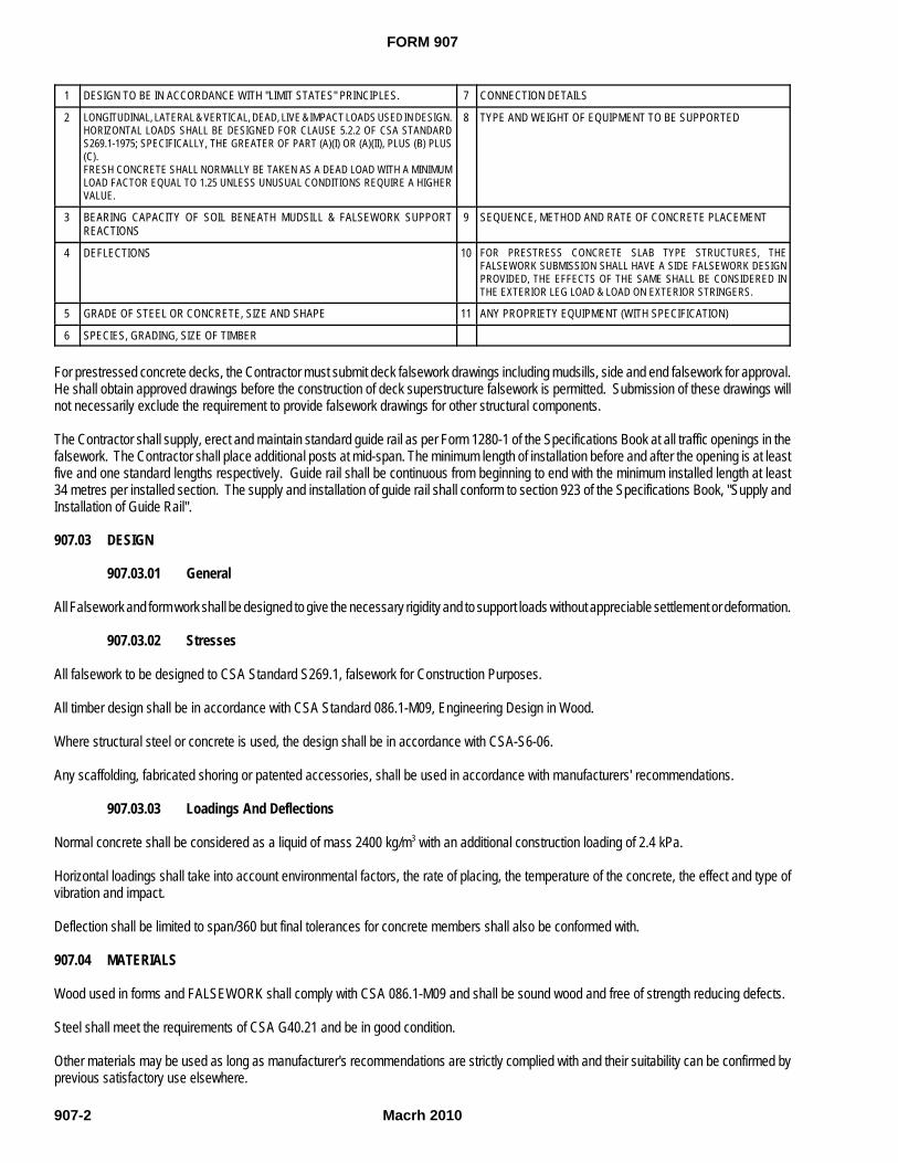
FORM 907
Macrh 2010907-2
1 DESIGN TO BE IN ACCORDANCE WITH "LIMIT STATES" PRINCIPLES. 7 CONNECTION DETAILS
2 LONGITUDINAL, LATERAL & VERTICAL, DEAD, LIVE & IMPACT LOADS USED IN DESIGN.HORIZONTAL LOADS SHALL BE DESIGNED FOR CLAUSE 5.2.2 OF CSA STANDARDS269.1-1975; SPECIFICALLY, THE GREATER OF PART (A)(I) OR (A)(II), PLUS (B) PLUS(C).FRESH CONCRETE SHALL NORMALLY BE TAKEN AS A DEAD LOAD WITH A MINIMUMLOAD FACTOR EQUAL TO 1.25 UNLESS UNUSUAL CONDITIONS REQUIRE A HIGHERVALUE.
8 TYPE AND WEIGHT OF EQUIPMENT TO BE SUPPORTED
3 BEARING CAPACITY OF SOIL BENEATH MUDSILL & FALSEWORK SUPPORTREACTIONS
9 SEQUENCE, METHOD AND RATE OF CONCRETE PLACEMENT
4 DEFLECTIONS 10 FOR PRESTRESS CONCRETE SLAB TYPE STRUCTURES, THEFALSEWORK SUBMISSION SHALL HAVE A SIDE FALSEWORK DESIGNPROVIDED, THE EFFECTS OF THE SAME SHALL BE CONSIDERED INTHE EXTERIOR LEG LOAD & LOAD ON EXTERIOR STRINGERS.
5 GRADE OF STEEL OR CONCRETE, SIZE AND SHAPE 11 ANY PROPRIETY EQUIPMENT (WITH SPECIFICATION)
6 SPECIES, GRADING, SIZE OF TIMBER
For prestressed concrete decks, the Contractor must submit deck falsework drawings including mudsills, side and end falsework for approval.He shall obtain approved drawings before the construction of deck superstructure falsework is permitted. Submission of these drawings willnot necessarily exclude the requirement to provide falsework drawings for other structural components.
The Contractor shall supply, erect and maintain standard guide rail as per Form 1280-1 of the Specifications Book at all traffic openings in thefalsework. The Contractor shall place additional posts at mid-span. The minimum length of installation before and after the opening is at leastfive and one standard lengths respectively. Guide rail shall be continuous from beginning to end with the minimum installed length at least34 metres per installed section. The supply and installation of guide rail shall conform to section 923 of the Specifications Book, "Supply andInstallation of Guide Rail".
907.03 DESIGN
907.03.01 General
All Falsework and form work shall be designed to give the necessary rigidity and to support loads without appreciable settlement or deformation.
907.03.02 Stresses
All falsework to be designed to CSA Standard S269.1, falsework for Construction Purposes.
All timber design shall be in accordance with CSA Standard 086.1-M09, Engineering Design in Wood.
Where structural steel or concrete is used, the design shall be in accordance with CSA-S6-06.
Any scaffolding, fabricated shoring or patented accessories, shall be used in accordance with manufacturers' recommendations.
907.03.03 Loadings And Deflections
Normal concrete shall be considered as a liquid of mass 2400 kg/m3 with an additional construction loading of 2.4 kPa.
Horizontal loadings shall take into account environmental factors, the rate of placing, the temperature of the concrete, the effect and type ofvibration and impact.
Deflection shall be limited to span/360 but final tolerances for concrete members shall also be conformed with.
907.04 MATERIALS
Wood used in forms and FALSEWORK shall comply with CSA 086.1-M09 and shall be sound wood and free of strength reducing defects.
Steel shall meet the requirements of CSA G40.21 and be in good condition.
Other materials may be used as long as manufacturer's recommendations are strictly complied with and their suitability can be confirmed byprevious satisfactory use elsewhere.

FORM 907
Macrh 2010 907-3
Void tubes made of fibrous material shall be protected from damage and water attack at all times.
Materials rejected shall be removed from the job site immediately, as directed by the Engineer.
907.05 FORM WORK CONSTRUCTION
For concrete pours above 3.0 metres in height or if so requested by the Engineer, Shop Drawings of form work shall be provided. Form Workdrawings shall be signed and sealed by a licenced member of the Association of Professional Engineers of Newfoundland.
Form Work Shop drawings shall account for the following:
1. Design to be in accordance with limit state principles;
2. Pour pressures exerted by the liquid head of concrete;
3. Sequence method and rate of concrete placement;
4. Species and grade of timber;
5. Concrete admixtures and dosage rates ( i.e. plasticizers and set retarders).
Forms shall be smooth, clean, free from warps, splits, holes and bulges and shall be constructed and maintained mortar tight. Plywood shallbe used on all exposed faces.
Non-staining form release oil shall be applied to the faces of forms prior to reinforcement placement.
For buried non-exposed surfaces and for all substructure concrete surfaces on bridge structures form work ties, tie wire, bolts and rods shallhave no metal within 25 mm of the concrete surface after form removal. The 25mm cover shall be provided by means of plastic cones adjacentto the exposed concrete surface. In no case will the cutting back of metal ties or tie wire be permitted after the concrete has cured. In no casewill the use of tubing be permitted to allow the recovery of ties. Cavities left as a result of ties shall be filled with a cement mortar and thesurface left sound, smooth, even and uniform in color.
As practical fibreglass ties shall be used on all superstructure concrete surfaces and for all exposed substructure concrete surfaces onoverpass/underpass structures.
On concrete Jersey barriers where form liner has been attached to one side, a tapered rod system may be utilized. The void remaining afterthe tapered rod has been removed from the concrete shall be filled with grout.
The grout and grouting procedure must be consistent throughout the project and be approved by the Engineer. The grout shall blend in withthe finished concrete surface and the finished appearance shall be uniform.
All exposed corners on concrete work shall be chamfered 25 mm.
Stay in place forms shall be used only when detailed in the contract or if approved by the Engineer.
Void tubes shall be accurately and rigidly fixed in position and carefully restrained from floatation.
Studs and joints shall be at centres not exceeding 400 mm. Edges of abutting sheets shall be nailed to the same stud or joint with 50 mm nailsat centres not exceeding 200 mm. Jointing shall be regular and flush.
907.05.01 Supply and Installation of Form Liner
Where indicated in contract documents the Contractor shall supply and install a form liner. The form liner pattern shall be as identified in theContract drawings.
The material type may be SPS or ABS plastic depending upon how the Contractor schedules the work, as approved by the Engineer andanticipated future requirements.
The form liner shall be approximately 610mm high and be located such that approximately 140mm of untextured concrete barrier wall surfaceis located above and below the form liner. The horizontal distance from the end of the barrier to the beginning of the form liner shall be 150mm.The 150mm dimension shall also be applied at expansion joint locations.

FORM 907
Macrh 2010907-4
The Contractor shall verify lines, levels and centres before proceeding with the form work and ensure that dimensions agree with drawings.The form liner shall be strictly installed in accordance with the Manufacturer’s application guide to achieve design requirements. The Contractorshall arrange and assemble form work to permit dismantling and stripping. No damage is permitted to concrete surfaces during stripping. The form release agent shall be applied on the liner in accordance with the manufacturer’s recommendations. The form release agent shallbe applied prior to placing reinforcing steel, anchoring devices and embedded items. The forms are to be loosened carefully. The Contractorshall not wedge pry bars, hammers, or tools against concrete surfaces scheduled for exposure to view.
The Contractor shall plan ahead for details such as: concrete mix design, concrete placing practices, attaching liners and sealing the joints,tie selection and tie-hole treatment, reinforcing positioning, release agents and stripping in addition to cleaning and storage of form liners and forms.
The Contractor shall use one concrete supplier, one source of aggregates and cement. An elephant trunk shall be used to prevent spatteredconcrete if the form is not completely filled in the first concrete operation. Falling concrete shall not be permitted to cause abrasion to the formliner. The rate of concrete placing shall not exceed the allowable pressure on the form liner.
The Contractor is reminded to use adequate vibration to avoid lift lines and reduce bugholes. Extra vibration is needed when using plastic linersbecause they have two or three times as much surface area as flat form panels. Vibrators shall be inserted vertically, penetrating at least 150mm into the previous lift. Vibrators shall not touch the liner surfaces.
The Contractor shall consider temperature effects when cutting and installing liner materials. Form liner should not be exposed to direct sunin order to reduce buckling effects.
The Contractor shall give close attention to tight-fitting tie holes, reinforcing bar supports and spacers. Bar supports should be coordinatedwith the repeat pattern of the liner.
Cover shall be measured from the deepest indentation in the concrete surface to the nearest face of the bar.
Release agents and form liners shall be checked for compatibility before use.
Form liner stripping shall be recommended by the Manufacturer and approved by the Engineer. Stripping shall be kept uniform throughoutthe entire job.
Form liners shall be clean and should be stored in shaded or covered areas.
Construction practice and materials must be consistent throughout the entire concrete placing operation where form liners are utilized.
Measurement for Payment
Measurement for Payment shall be in square metres rounded to the nearest one (1) decimal place. Measurement for payment shall be surfacelength treated or covered with form liner times the nominal height of 0.610 metres. Deductions will not be made for trimming the form liner inorder to conform to the ends of the barrier wall but deductions will be made for the length not treated with form liner such as at expansion jointlocations.
Basis of Payment
The basis of payment shall be full compensation for all plant, labour, materials and equipment to supply, transport to the job site and installand remove form liner as described above.
907.06 FALSEWORK CONSTRUCTION
The Contractor shall build sound adjustable falsework to enable a structure true to line and grade to be built.
Foundation material shall either be piled or mudsills depending on bearing capacity. Mudsills shall be of minimum dimension 235 mm x 89 mm.
Care shall be taken to prevent reduction of bearing capacity due to environmental, construction or any other reason.
Should, despite every precaution, reduction of bearing capacity occur, the Contractor shall take appropriate measures to eliminate subsidenceor collapse.
All shoring shall conform to CSA S269.1
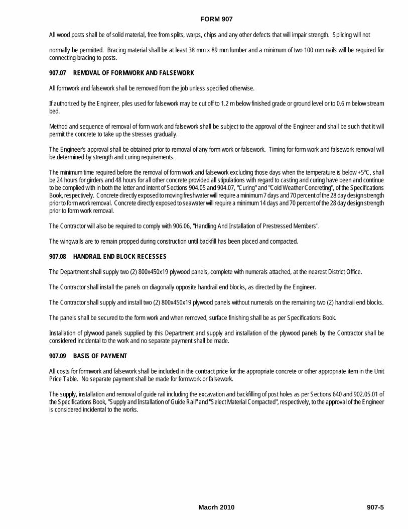
FORM 907
Macrh 2010 907-5
All wood posts shall be of solid material, free from splits, warps, chips and any other defects that will impair strength. Splicing will not
normally be permitted. Bracing material shall be at least 38 mm x 89 mm lumber and a minimum of two 100 mm nails will be required forconnecting bracing to posts.
907.07 REMOVAL OF FORMWORK AND FALSEWORK
All formwork and falsework shall be removed from the job unless specified otherwise.
If authorized by the Engineer, piles used for falsework may be cut off to 1.2 m below finished grade or ground level or to 0.6 m below streambed.
Method and sequence of removal of form work and falsework shall be subject to the approval of the Engineer and shall be such that it willpermit the concrete to take up the stresses gradually.
The Engineer's approval shall be obtained prior to removal of any form work or falsework. Timing for form work and falsework removal willbe determined by strength and curing requirements.
The minimum time required before the removal of form work and falsework excluding those days when the temperature is below +5oC, shallbe 24 hours for girders and 48 hours for all other concrete provided all stipulations with regard to casting and curing have been and continueto be complied with in both the letter and intent of Sections 904.05 and 904.07, "Curing" and "Cold Weather Concreting", of the SpecificationsBook, respectively. Concrete directly exposed to moving freshwater will require a minimum 7 days and 70 percent of the 28 day design strengthprior to form work removal. Concrete directly exposed to seawater will require a minimum 14 days and 70 percent of the 28 day design strengthprior to form work removal.
The Contractor will also be required to comply with 906.06, "Handling And Installation of Prestressed Members".
The wingwalls are to remain propped during construction until backfill has been placed and compacted.
907.08 HANDRAIL END BLOCK RECESSES
The Department shall supply two (2) 800x450x19 plywood panels, complete with numerals attached, at the nearest District Office.
The Contractor shall install the panels on diagonally opposite handrail end blocks, as directed by the Engineer.
The Contractor shall supply and install two (2) 800x450x19 plywood panels without numerals on the remaining two (2) handrail end blocks.
The panels shall be secured to the form work and when removed, surface finishing shall be as per Specifications Book.
Installation of plywood panels supplied by this Department and supply and installation of the plywood panels by the Contractor shall beconsidered incidental to the work and no separate payment shall be made.
907.09 BASIS OF PAYMENT
All costs for formwork and falsework shall be included in the contract price for the appropriate concrete or other appropriate item in the UnitPrice Table. No separate payment shall be made for formwork or falsework.
The supply, installation and removal of guide rail including the excavation and backfilling of post holes as per Sections 640 and 902.05.01 ofthe Specifications Book, "Supply and Installation of Guide Rail" and "Select Material Compacted", respectively, to the approval of the Engineeris considered incidental to the works.
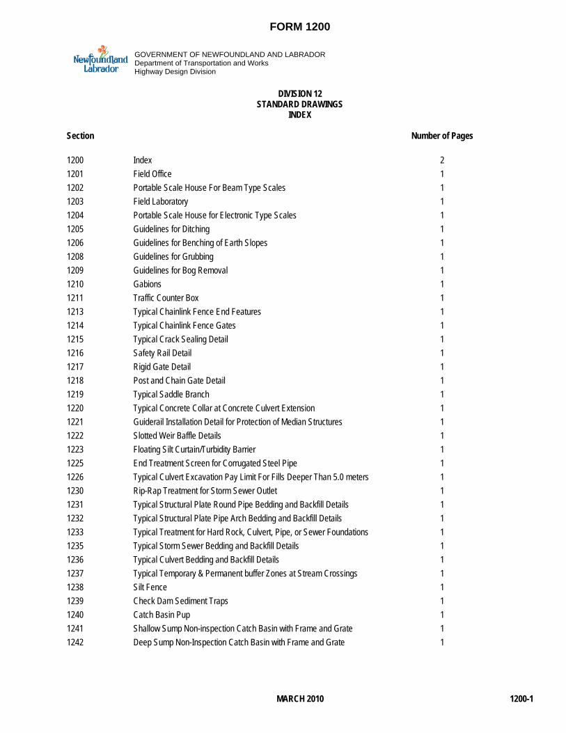
FORM 1200
MARCH 2010 1200-1
GOVERNMENT OF NEWFOUNDLAND AND LABRADORDepartment of Transportation and WorksHighway Design Division
DIVISION 12STANDARD DRAWINGS
INDEX
Section Number of Pages
1200 Index 21201 Field Office 11202 Portable Scale House For Beam Type Scales 11203 Field Laboratory 11204 Portable Scale House for Electronic Type Scales 11205 Guidelines for Ditching 11206 Guidelines for Benching of Earth Slopes 11208 Guidelines for Grubbing 11209 Guidelines for Bog Removal 11210 Gabions 11211 Traffic Counter Box 11213 Typical Chainlink Fence End Features 11214 Typical Chainlink Fence Gates 11215 Typical Crack Sealing Detail 11216 Safety Rail Detail 11217 Rigid Gate Detail 11218 Post and Chain Gate Detail 11219 Typical Saddle Branch 11220 Typical Concrete Collar at Concrete Culvert Extension 11221 Guiderail Installation Detail for Protection of Median Structures 11222 Slotted Weir Baffle Details 11223 Floating Silt Curtain/Turbidity Barrier 11225 End Treatment Screen for Corrugated Steel Pipe 11226 Typical Culvert Excavation Pay Limit For Fills Deeper Than 5.0 meters 11230 Rip-Rap Treatment for Storm Sewer Outlet 11231 Typical Structural Plate Round Pipe Bedding and Backfill Details 11232 Typical Structural Plate Pipe Arch Bedding and Backfill Details 11233 Typical Treatment for Hard Rock, Culvert, Pipe, or Sewer Foundations 11235 Typical Storm Sewer Bedding and Backfill Details 11236 Typical Culvert Bedding and Backfill Details 11237 Typical Temporary & Permanent buffer Zones at Stream Crossings 11238 Silt Fence 11239 Check Dam Sediment Traps 11240 Catch Basin Pup 11241 Shallow Sump Non-inspection Catch Basin with Frame and Grate 11242 Deep Sump Non-Inspection Catch Basin with Frame and Grate 1

FORM 1200
MARCH 20101200-2
1245 Single Inlet Standard Inspection Catch Basin 11247 Single Inlet Large Inspection Catch Basin 11250 Twin Inlet Catch Basin 11255 600 x 600 Ditch Inlet Catch Basin 11256 1000 x 1000 Ditch Inlet Catch Basin 11256a Modified 1000 x 1000 Ditch Inlet Catch Basin 11257 1200 x 1200 Ditch Inlet Catch Basin 11260 Typical Ditch Inlet Grating Detail 11263 Standard Frame and Grate for Catch Basin 11264 Type V Frame and Grate for Catch Basins 11266 Curb and Gutter Casting 11269 Round Manhole Frame and Grate 11270 Manhole Frame and Mortar Detail 11272 Asphalt Sidewalk 11273 Asphalt Gutter 11274 Asphalt Curb 11275 Concrete Curbs Types C, D, G, and H 11276 Typical Drop Curb with Sidewalk Layout 11277 Typical Curb and Gutter Tapered End Treatment 11278 Paraplegic Ramp 11279 Typical Guide Rail Installation Types 11280 Guide Rail Standard Installation 11281 Signal Reflectors on Guide Rail Post 11282 Guide Rail with Additional Posts 11283 Concrete Encased Duct Banks 11284 Electrical Junction Box 11285 Wooden Guide Post 11286 Foundation for Post Top Traffic Light 11287 Foundation for Cantilevered Traffic Light 11288a Foundation for Traffic Controller 11288b Traffic Control Prefab Junction Box 11288c Type 1 Installation of Preformed Inductive Loop Placement in New Road 11288d Type 2 Installation of Preformed Inductive Loop Placement in Existing Road 11288e Asphalt Cut Inductive Loop 11289 Cast in Place Concrete Median Barrier 11290 Sign Post Installation Details Type "A" 11291 Sign Post Installation Details Type "B" 11292 Sign Post Installation Details Type "C" 11293 Sign Post Installation Details Type "D" 11294 Sign Post Installation Details Type "E" 11294a Sign Post Installation Details Type "H" 11295 Sign Post Installation Details Type "F" 11296 Sign Post Installation Details Type "G" 11296a Sign Post Installation Details Type "I" 11297 Telspar Yielding Break away System 11298 Sub-Grade Widening for Type "A and "B" Sign Post Installations 1

FORM 1200
MARCH 2010 1200-3
1299 Sub-Grade Widening for Type "C", "D", and "E" Sign Post Installations 11299a Sub-Grade Widening for Type "F","G", “H”, and "i" Sign Post Installations 1
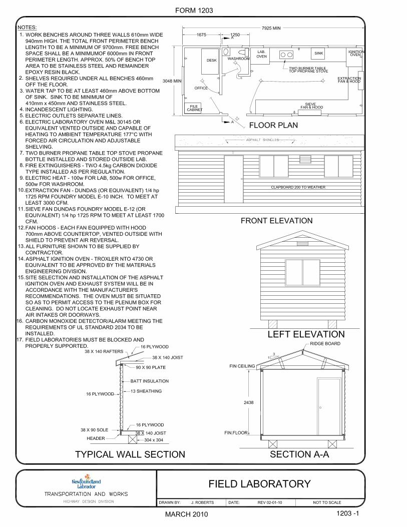

FORM 1288a
FOUNDATION FORTRAFFIC CONTROLLER
DATE: REV 02-01-10DRAWN BY: H. JONES
PLAN VIEW
SECTION A-A
900
150 150
B
A
A
100 GRANULAR "B"
475
SECTION B-B
750
150
900
300
300
CONDUITS AS REQUIRED75 P.V.C. ELECTRICAL
1500
B
NOTES:1. CONCRETE 30 MPa2. ALL EXPOSED EDGES TO BE CHAMFERED 25.
NOT TO SCALE
JANUARY 2010

FORM 1288b
TRAFFIC CONTROL PREFAB JUNCTIONBOX QUAZITE COMPOSOLITE
February 16, 2010DATE:DRAWN BY: NOT TO SCALE
JANUARY 2010
TRAFFIC
NOTES:
1. TOP OF BOX TO BE PLACED FLUSH WITH TOP OF SIDEWALK OR FINAL GRADE.
2. COVER TO HAVE TRAFFIC LOGO IMPRINTED ON TOP.
3. APPROVED MANUFACTURER QUAZITE COMPOSOLITE 3621 INDUSTRIAL PARK DR. LENOIR CITY, TENNESSEE 37771 TEL. : 800/346-3062
COVER: PG1324HA00 BOX: PG1324BA12
ELECTRICAL CONDUITSAS REQUIRED
GRANULAR "B"ROAD GRAVEL
FINISHGRADE
610
330
300
600
100
TOP VIEW
ELEVATION
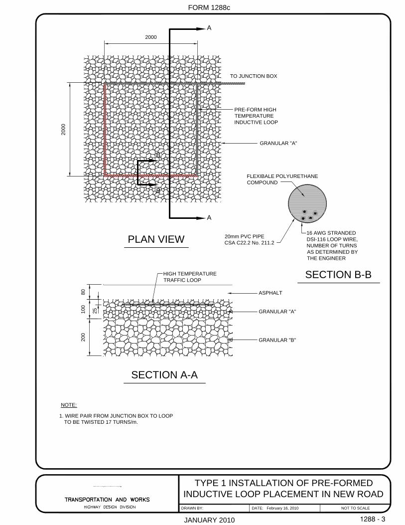
FORM 1288c
TYPE 1 INSTALLATION OF PRE-FORMEDINDUCTIVE LOOP PLACEMENT IN NEW ROAD
February 16, 2010DATE:DRAWN BY: NOT TO SCALE
JANUARY 2010
ASPHALT
GRANULAR "A"
GRANULAR "B"
A
A
GRANULAR "A"
B
B
TO JUNCTION BOX
1. WIRE PAIR FROM JUNCTION BOX TO LOOP TO BE TWISTED 17 TURNS/m.
NOTE:
8020
010
0
2000
2000
25
SECTION A-A
PLAN VIEW
SECTION B-B
20mm PVC PIPECSA C22.2 No. 211.2
16 AWG STRANDEDDSI-116 LOOP WIRE,NUMBER OF TURNSAS DETERMINED BYTHE ENGINEER
FLEXIBALE POLYURETHANECOMPOUND
PRE-FORM HIGHTEMPERATUREINDUCTIVE LOOP
HIGH TEMPERATURETRAFFIC LOOP

FORM 1288d
TYPE 2 INSTALLATION OF PRE-FORMEDINDUCTIVE LOOP PLACEMENT IN EXISTING ROAD
DATE: February 16, 2010DRAWN BY: NOT TO SCALE
JANUARY 2010
ASPHALT
GRANULAR "A"
GRANULAR "B"
HIGH TEMPERATURETRAFFIC LOOP
FLEXIBALE POLYURETHANECOMPOUND
16 AWG STRANDEDDSI-116 LOOP WIRE20mm PVC PIPE
CSA C22.2 No. 211.2
NOTE:
8020
010
0
25
NUMBER OF TURNSAS DETERMINED BY THE ENGINEER
40
40
2900
2300
WIRE PAIR FROM JUNCTION BOX TO LOOP TO BE TWISTED 17 TURNS/m.
TOP 40mm OF ASPHALT TO BE GROUND OUT AT A WIDTH OF 2900mm.
REMAINING 40mm OF ASPHALT TO BE SAW CUT OUT AT A WIDTH OF 2300mm.
ASPHALT SHALL BE REINSTATED AS PER SECTION 330 OF SPECIFICATIONS.
1.
2.
3.
TO JUNCTION BOX
PRE-FORMED HIGHTEMPERATURE INDUCTIVELOOPS
LIMIT OF SAW CUT
LIMIT OF GRINDING
6900
6300
2900
2300 300300
2000
2000
2000
A A
B
B
300
1000
3.
GROUND OUT SECTIONSAW CUT SECTION
PLAN VIEW
SECTION A-A
SECTION B-B

FORM 1288e
ASPHALT CUT INDUCTIVE LOOPDATE: February 16, 2010DRAWN BY: NOT TO SCALE
JANUARY 2010
SECTION A-A SECTION B-B
A
A
1. SEALANT TO SET AROUND & OVERENTIRE WIRE AND BACKER ROD.
NOTE:
2000
2000
300
300
B
BTO JUNCTION BOX
10mm DIAMOND BLADE SAW CUT50mm DEEP, TWISTED WIRE PAIR15 TURNS/m.
5mm DIAMOND BLADE SAW CUT50mm DEEP.
5
50
10
TRAFFIC LOOP SEALANT
BACKER ROD
16 AWG STRANDEDDSI-116 LOOP WIRE
2. PLACE 100mm PIECES OF BACKER RODINTERMITTENTLY TO KEEP WIRE IN PLACEWHILE POURING TRAFFIC LOOP SEALENT.