government women engineering college...
TRANSCRIPT

Government Women Engineering College Ajmer Department of Electronics and Communication Engineering
I Mid Term Examination – 2018
Class: B.Tech. VI sem ECE Subject: Digital Communication
Date: 16/2/2018 Time: 1 Hr. MM: 20
1. Explain advantages of digital communication systems. . (5)
2. Explain PCM with the help of block diagram and involved processes involved. (5)
3. Deduce Quantization noise power in PCM. (5)
4. Explain different types of quantization in detail. (5)
5. Give expression and draw output waveform for following line codes: (5)
Input sequence: 10110100101
a. Unipolar NRZ
b. Polar NRZ
c. Bipolar NRZ
d. Manchester
e. AMI
Answer-1
Advantages of Digital Communication:
There are many advantages of using Digital Communication over analog Communication.
Some of them are listed as below:
1. The digital communication has mostly common structure of encoding a signal so
devices used are mostly similar.
2. The Digital Communication's main advantage is that it provides us added security to
our information signal.
3. The digital Communication system has more immunity to noise and external
interference.
4. Digital information can be saved and retrieved when necessary while it is not possible
in analog.
5. Digital Communication is cheaper than Analog Communication.
6. The configuring process of digital communication system is simple as compared to
analog communication system. Although, they are complex.
7. In Digital Communication System, the error correction and detection techniques can
be implemented easily.
Answer-2
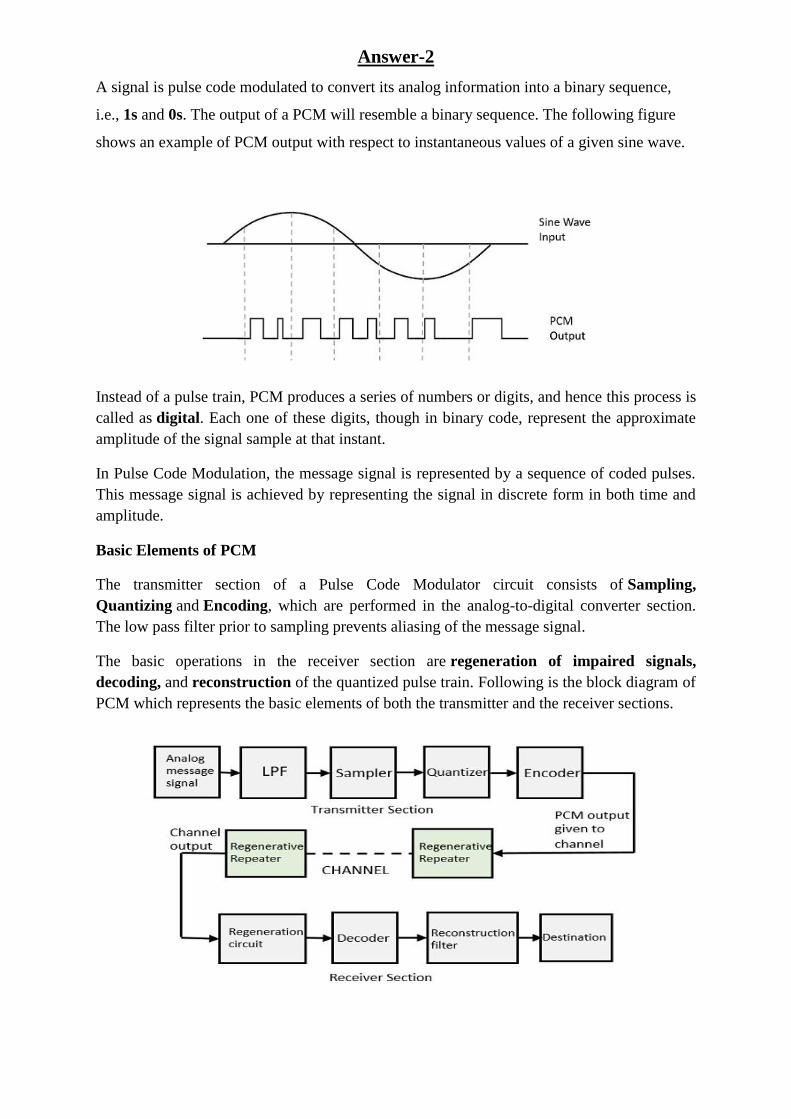
A signal is pulse code modulated to convert its analog information into a binary sequence,
i.e., 1s and 0s. The output of a PCM will resemble a binary sequence. The following figure
shows an example of PCM output with respect to instantaneous values of a given sine wave.
Instead of a pulse train, PCM produces a series of numbers or digits, and hence this process is
called as digital. Each one of these digits, though in binary code, represent the approximate
amplitude of the signal sample at that instant.
In Pulse Code Modulation, the message signal is represented by a sequence of coded pulses.
This message signal is achieved by representing the signal in discrete form in both time and
amplitude.
Basic Elements of PCM
The transmitter section of a Pulse Code Modulator circuit consists of Sampling,
Quantizing and Encoding, which are performed in the analog-to-digital converter section.
The low pass filter prior to sampling prevents aliasing of the message signal.
The basic operations in the receiver section are regeneration of impaired signals,
decoding, and reconstruction of the quantized pulse train. Following is the block diagram of
PCM which represents the basic elements of both the transmitter and the receiver sections.

Low Pass Filter
This filter eliminates the high frequency components present in the input analog signal which
is greater than the highest frequency of the message signal, to avoid aliasing of the message
signal.
Sampler
This is the technique which helps to collect the sample data at instantaneous values of
message signal, so as to reconstruct the original signal. The sampling rate must be greater
than twice the highest frequency component Wof the message signal, in accordance with the
sampling theorem.
Quantizer
Quantizing is a process of reducing the excessive bits and confining the data. The sampled
output when given to Quantizer, reduces the redundant bits and compresses the value.
Encoder
The digitization of analog signal is done by the encoder. It designates each quantized level by
a binary code. The sampling done here is the sample-and-hold process. These three sections
(LPF, Sampler, and Quantizer) will act as an analog to digital converter. Encoding minimizes
the bandwidth used.
Regenerative Repeater
This section increases the signal strength. The output of the channel also has one regenerative
repeater circuit, to compensate the signal loss and reconstruct the signal, and also to increase
its strength.
Decoder
The decoder circuit decodes the pulse coded waveform to reproduce the original signal. This
circuit acts as the demodulator.
Reconstruction Filter
After the digital-to-analog conversion is done by the regenerative circuit and the decoder, a
low-pass filter is employed, called as the reconstruction filter to get back the original signal.
Hence, the Pulse Code Modulator circuit digitizes the given analog signal, codes it and
samples it, and then transmits it in an analog form. This whole process is repeated in a
reverse pattern to obtain the original signal.
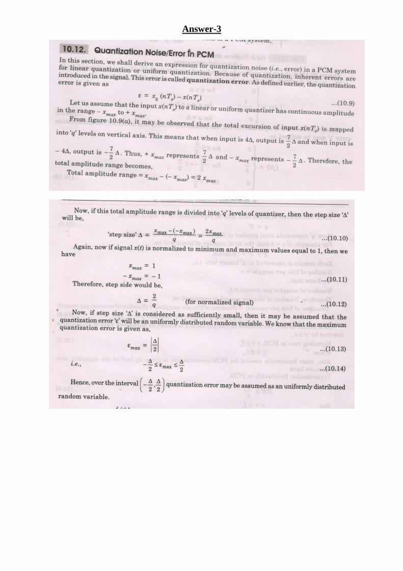
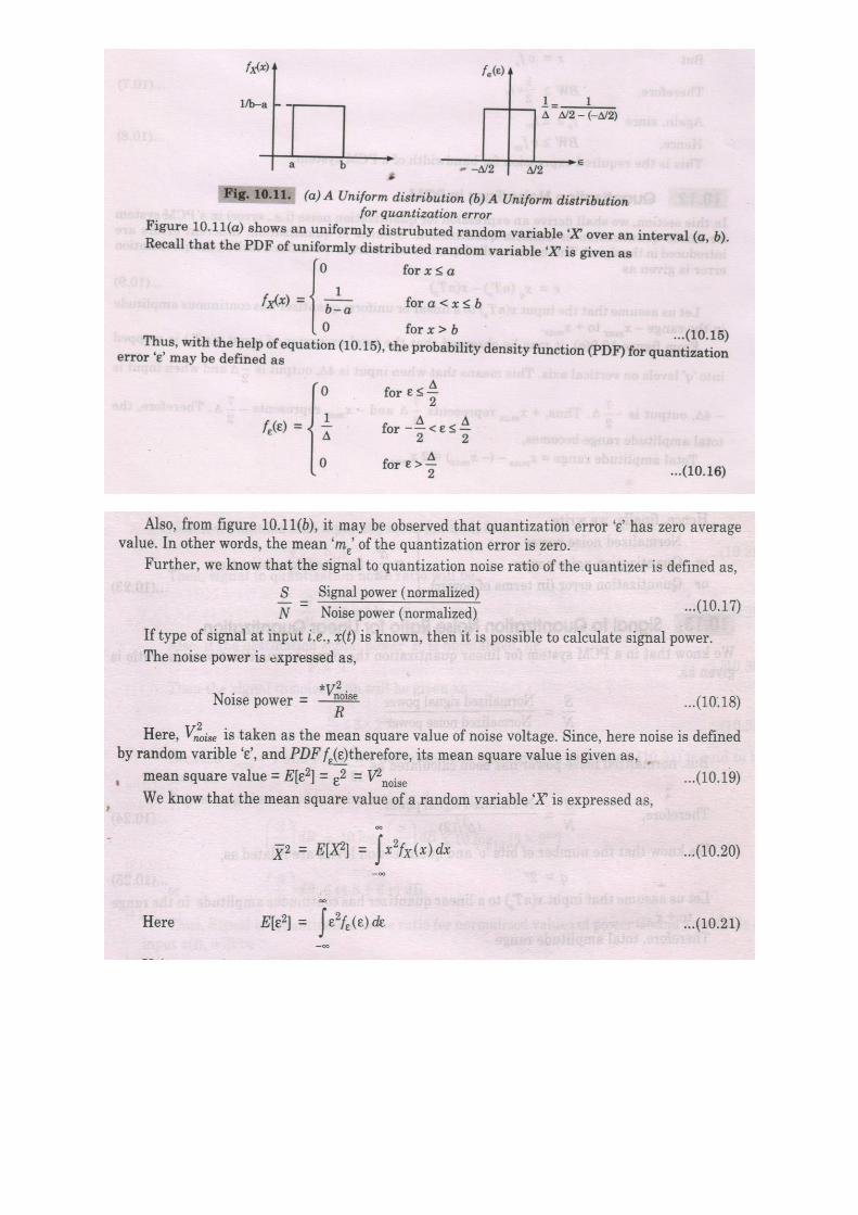
Answer-3


Answer-4
Types of Quantizers:
1. Uniform Quantizer
2. Non- Uniform Quantizer
Uniform Quantizer: In Uniform type, the quantization levels are uniformly spaced,
whereasin non-uniform type the spacing between the levels will be unequal and mostly the
relation is logarithmic.
Types of Uniform Quantizers: ( based on I/P - O/P Characteristics)
1. Mid-Rise type Quantizer
2. Mid-Tread type Quantizer
In the stair case like graph, the origin lies the middle of the tread portion in Mid –Tread type
where as the origin lies in the middle of the rise portion in the Mid-Rise type.
Mid – tread type:Quantization levels – odd number.
Mid – Rise type: Quantization levels – even number.
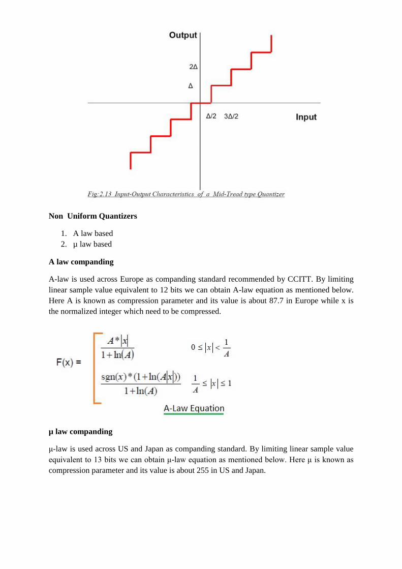
Non Uniform Quantizers
1. A law based
2. µ law based
A law companding
A-law is used across Europe as companding standard recommended by CCITT. By limiting
linear sample value equivalent to 12 bits we can obtain A-law equation as mentioned below.
Here A is known as compression parameter and its value is about 87.7 in Europe while x is
the normalized integer which need to be compressed.
µ law companding
μ-law is used across US and Japan as companding standard. By limiting linear sample value
equivalent to 13 bits we can obtain μ-law equation as mentioned below. Here μ is known as
compression parameter and its value is about 255 in US and Japan.

Answer-5
a. Unipolar NRZ
b. Polar NRZ
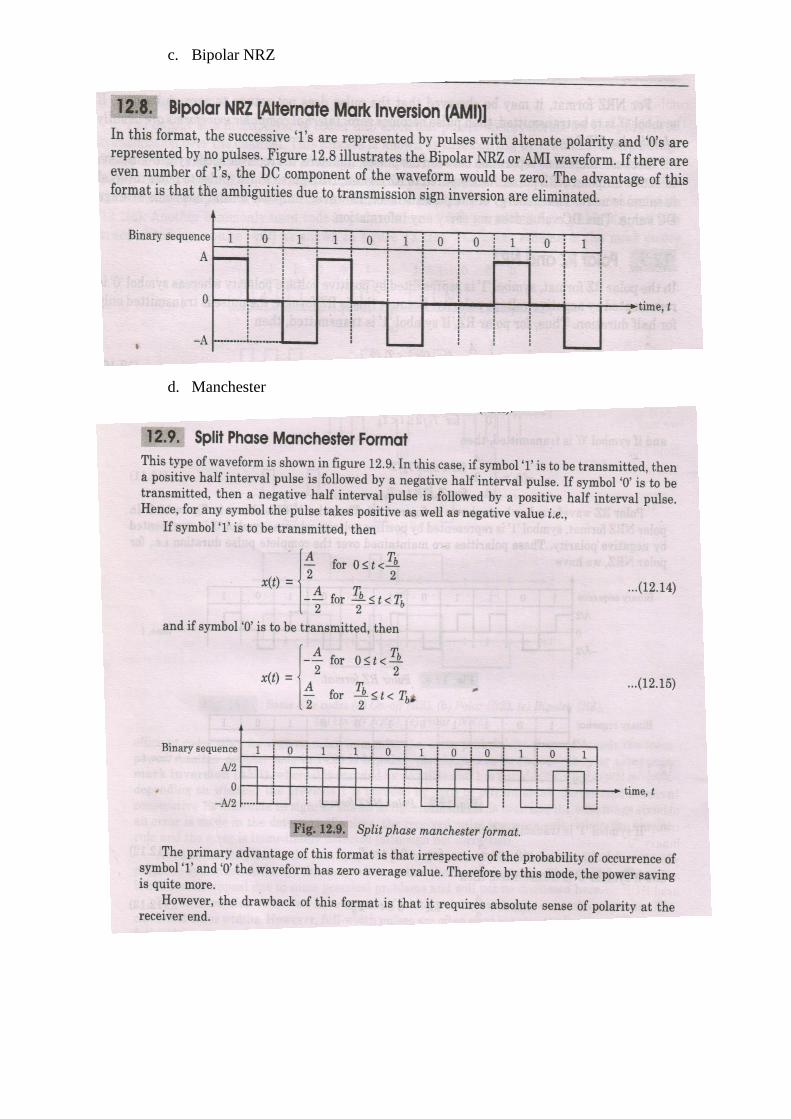
c. Bipolar NRZ
d. Manchester

e. AMI