gp12, gp15, gp18 - mbw (uk) limited · the mbw gp12, gp15, gp18 compactors are intended to compact...
TRANSCRIPT
OPERATOR’S SAFETY AND SERVICE MANUAL
MBW, Inc.250 Hartford Rd • PO Box 440Slinger, WI 53086-0440Phone: (262) 644-5234Fax: (262) 644-5169Email: [email protected]: www.mbw.com
MBW (UK) Ltd.Units 2&3 CochraneStreetBolton BL3 6BNEngland, UKPhone: 44 (0) 01204 387784Fax: 44 (0) 01204 387797E-mail: [email protected]
MBW FRANCE S.A.R.L.Z.A. d’Outreville11 Rue Jean Baptiste Néron,60540 BORNELFranceEmail: [email protected]:+33 (0) 3 44 07 15 96Fax: +33 (0) 3 44 07 41 28
L20411 / 08.12.A©MBW, Inc. 2004Printed in the USA
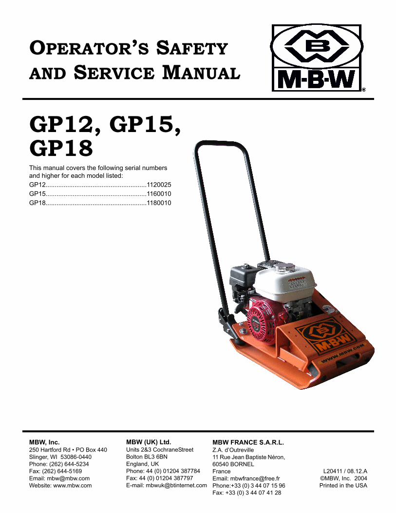
GP12, GP15, GP18This manual covers the following serial numbersand higher for each model listed:
GP12........................................................1120025
GP15........................................................1160010
GP18........................................................1180010
TABLE OF CONTENTS
Safety Information . . . . . . . . . . . . . . . . . . . . . . 1
Introduction . . . . . . . . . . . . . . . . . . . . . . . . . . . . . . . . . 1
Safety Precautions . . . . . . . . . . . . . . . . . . . . . . . . . . . 1
Safety Decals . . . . . . . . . . . . . . . . . . . . . . . . . . . . . . . 2
Specifications. . . . . . . . . . . . . . . . . . . . . . . . . . 3
Operation . . . . . . . . . . . . . . . . . . . . . . . . . . . . . 4
Introduction . . . . . . . . . . . . . . . . . . . . . . . . . . . . . . . . . 4
Before Starting & Operating . . . . . . . . . . . . . . . . . . . . 4
Starting Engine . . . . . . . . . . . . . . . . . . . . . . . . . . . . . . 4
Operating . . . . . . . . . . . . . . . . . . . . . . . . . . . . . . . . . . 4
Stopping Engine . . . . . . . . . . . . . . . . . . . . . . . . . . . . . 4
Lifting/Transporting . . . . . . . . . . . . . . . . . . . . . . . . . . . 4
Maintenance . . . . . . . . . . . . . . . . . . . . . . . . . . . 6
Maintenance Schedule . . . . . . . . . . . . . . . . . . . . . . . . 6
Fluid Levels. . . . . . . . . . . . . . . . . . . . . . . . . . . . . . . . . 6
Engine Maintenance . . . . . . . . . . . . . . . . . . . . . . . . . . 6
Engine Speed . . . . . . . . . . . . . . . . . . . . . . . . . . . . . . . 6
Service. . . . . . . . . . . . . . . . . . . . . . . . . . . . . . . . 7
Torque Chart . . . . . . . . . . . . . . . . . . . . . . . . . . . . . . . 7
Service Tools . . . . . . . . . . . . . . . . . . . . . . . . . . . . . . . 7
Engine Maintenance. . . . . . . . . . . . . . . . . . . . . . . . . . 7
Engine RPM . . . . . . . . . . . . . . . . . . . . . . . . . . . . . . . . 7
Changing Exciter Oil. . . . . . . . . . . . . . . . . . . . . . . . . . 7
Cleanup . . . . . . . . . . . . . . . . . . . . . . . . . . . . . . . . . . . 7
Belt Adjustment . . . . . . . . . . . . . . . . . . . . . . . . . . . . . 8
Engine Removal . . . . . . . . . . . . . . . . . . . . . . . . . . . . . 8
Exciter Disassembly . . . . . . . . . . . . . . . . . . . . . . . . . . 8
Exciter Assembly . . . . . . . . . . . . . . . . . . . . . . . . . . . . 8
Parts Replacement Cycles and Tolerances . . . . . . . . 9
Replacement Parts . . . . . . . . . . . . . . . . . . . . . 10
. . . . . . . . . . . . . . . . . . . . . . . . . . . . . . . . . . . . . 11
EXCITER ASSEMBLY . . . . . . . . . . . . . . . . . . . . . . . 12
MAIN ASSEMBLY . . . . . . . . . . . . . . . . . . . . . . . . . . 14
HANDLE ASSEMBLY . . . . . . . . . . . . . . . . . . . . . . . 16
Warranty . . . . . . . . . . . . . . . . . . . . . . . . . . . . . 18

CALIFORNIA PROPOSITION 65 WARNINGEngine exhaust and some of its constituents are known in the state of California to cause cancer,
birth defects, and other reproductive harm.
WARNING
- 1 -
SAFETY INFORMATION
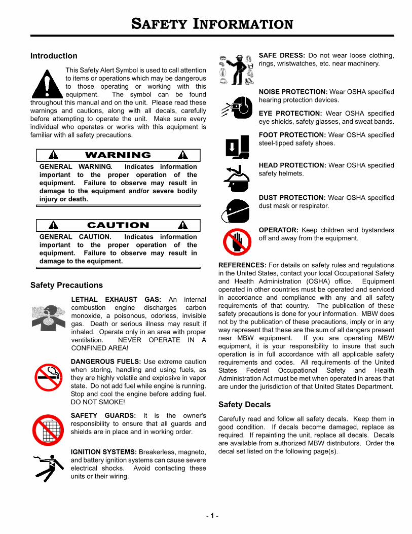
Introduction
This Safety Alert Symbol is used to call attentionto items or operations which may be dangerousto those operating or working with thisequipment. The symbol can be found
throughout this manual and on the unit. Please read thesewarnings and cautions, along with all decals, carefullybefore attempting to operate the unit. Make sure everyindividual who operates or works with this equipment isfamiliar with all safety precautions.
WARNINGGENERAL WARNING. Indicates informationimportant to the proper operation of theequipment. Failure to observe may result indamage to the equipment and/or severe bodilyinjury or death.
CAUTIONGENERAL CAUTION. Indicates informationimportant to the proper operation of theequipment. Failure to observe may result indamage to the equipment.
Safety Precautions
LETHAL EXHAUST GAS: An internalcombustion engine discharges carbonmonoxide, a poisonous, odorless, invisiblegas. Death or serious illness may result ifinhaled. Operate only in an area with properventilation. NEVER OPERATE IN ACONFINED AREA!
DANGEROUS FUELS: Use extreme cautionwhen storing, handling and using fuels, asthey are highly volatile and explosive in vaporstate. Do not add fuel while engine is running.Stop and cool the engine before adding fuel.DO NOT SMOKE!
SAFETY GUARDS: It is the owner'sresponsibility to ensure that all guards andshields are in place and in working order.
IGNITION SYSTEMS: Breakerless, magneto,and battery ignition systems can cause severeelectrical shocks. Avoid contacting theseunits or their wiring.
SAFE DRESS: Do not wear loose clothing,rings, wristwatches, etc. near machinery.
NOISE PROTECTION: Wear OSHA specifiedhearing protection devices.
EYE PROTECTION: Wear OSHA specifiedeye shields, safety glasses, and sweat bands.
FOOT PROTECTION: Wear OSHA specifiedsteel-tipped safety shoes.
HEAD PROTECTION: Wear OSHA specifiedsafety helmets.
DUST PROTECTION: Wear OSHA specifieddust mask or respirator.
OPERATOR: Keep children and bystandersoff and away from the equipment.
REFERENCES: For details on safety rules and regulationsin the United States, contact your local Occupational Safetyand Health Administration (OSHA) office. Equipmentoperated in other countries must be operated and servicedin accordance and compliance with any and all safetyrequirements of that country. The publication of thesesafety precautions is done for your information. MBW doesnot by the publication of these precautions, imply or in anyway represent that these are the sum of all dangers presentnear MBW equipment. If you are operating MBWequipment, it is your responsibility to insure that suchoperation is in full accordance with all applicable safetyrequirements and codes. All requirements of the UnitedStates Federal Occupational Safety and HealthAdministration Act must be met when operated in areas thatare under the jurisdiction of that United States Department.
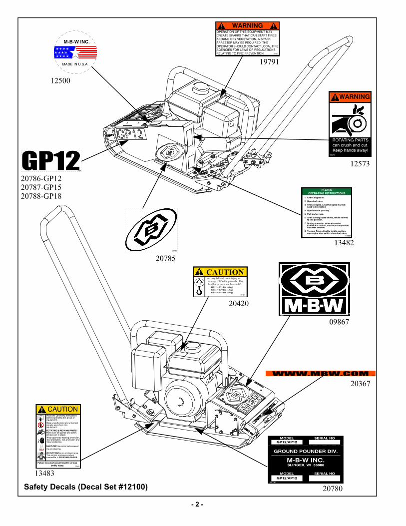
Safety Decals
Carefully read and follow all safety decals. Keep them ingood condition. If decals become damaged, replace asrequired. If repainting the unit, replace all decals. Decalsare available from authorized MBW distributors. Order thedecal set listed on the following page(s).
- 2 -
20785
09867
WWW.MBW.COM 20367
CAUTIONUnit may fall and cause injury or
damage if lifted improperly. Use handles on deck and base to lift.
20420
GP12 = 132 lbs (60kg)GP16 = 139 lbs (63kg)GP18 = 144 lbs (65kg)
Safety Decals (Decal Set #12100)
13483
CAUTION
Wear approved hearing protection, foot protection, eye protection and head protection.
STOP
Read the Operating Instructions before operating this piece of equipment.Keep unauthorized and untrained people away from this equipment.
ROTATING & MOVING PARTS! Make sure all guards and safety devices are in place.
Failure to comply could result in serious bodily injury.
SHUT OFF the motor before servic-ing or cleaning.
DO NOT RUN in an enclosed area. The engine produces carbon monoxide, a POISONOUS GAS.
12573
WARNING
ROTATING PARTS can crush and cut.Keep hands away!
������������ �����������
�� �����������������
�� ���������"#�"��
$� ����������������%#'*��������*#+���/����;�/��<�������;�
=� ����/�'�//����#'/�%#+�
>� �����?/#'/�'�'����
@� ��/�'�?/#'/���J�����������Y�'�/�'��/�'�//���/���;�����?�/����
[� \�'�������'#/���Y�%�����]��??�"������<#����?���/���;Y�*#]�*�*���*�#�/�����#?�<����'�#���;�
^� ���?/��J��/�'��/�'�//���/���;�����?�/���Y���?���������?/���?%�/��Y����?�������"#�"��
�$=^�
M-B-W INC.
MADE IN U.S.A.
MODEL SERIAL NO
SERIAL NOMODEL
M-B-W INC.SLINGER, WI 53086
GP12/AP12
GP12/AP12
GROUND POUNDER DIV.
20780
20786
19791
WARNINGOPERATION OF THIS EQUIPMENT MAY CREATE SPARKS THAT CAN START FIRES AROUND DRY VEGETATION. A SPARK ARRESTER MAY BE REQUIRED. THE OPERATOR SHOULD CONTACT LOCAL FIRE AGENCIES FOR LAWS OR REGULATIONS RELATING TO FIRE PREVENTION
12500
20786-GP12
20367
13483
20420
19791
12573
13482
09867
20785
20780
20787-GP1520788-GP18
- 3 -
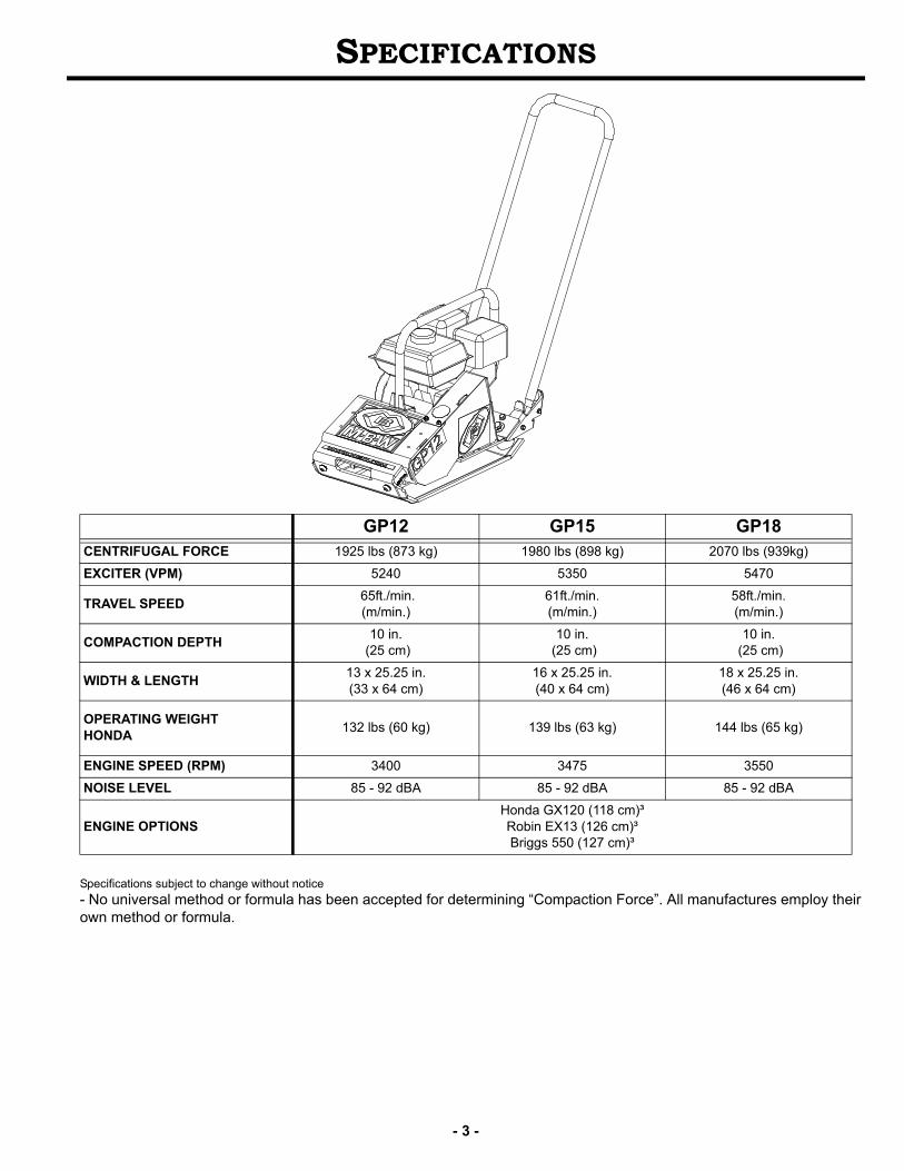
SPECIFICATIONS
Specifications subject to change without notice
- No universal method or formula has been accepted for determining “Compaction Force”. All manufactures employ their own method or formula.
GP12 GP15 GP18 CENTRIFUGAL FORCE 1925 lbs (873 kg) 1980 lbs (898 kg) 2070 lbs (939kg)
EXCITER (VPM) 5240 5350 5470
TRAVEL SPEED 65ft./min.(m/min.)
61ft./min.(m/min.)
58ft./min.(m/min.)
COMPACTION DEPTH10 in.
(25 cm)10 in.
(25 cm)10 in.
(25 cm)
WIDTH & LENGTH13 x 25.25 in.(33 x 64 cm)
16 x 25.25 in.(40 x 64 cm)
18 x 25.25 in.(46 x 64 cm)
OPERATING WEIGHT HONDA
132 lbs (60 kg) 139 lbs (63 kg) 144 lbs (65 kg)
ENGINE SPEED (RPM) 3400 3475 3550
NOISE LEVEL 85 - 92 dBA 85 - 92 dBA 85 - 92 dBA
ENGINE OPTIONSHonda GX120 (118 cm)³Robin EX13 (126 cm)³Briggs 550 (127 cm)³
OPERATION
Introduction
MBW equipment is intended for use in very severeapplications. They are powered by four cycle engines andare available in different sizes and a selection of engines.
This parts manual contains only standard parts. Variationsof these parts as well as other special parts are not included.Contact your local MBW distributor for assistance inidentifying parts not included in this manual.
The MBW GP12, GP15, GP18 compactors are intended tocompact various types of soil. Recommended soil typesinclude granular soils and gravel & sand mixtures. Thesecompactors are not intended to be used on cohesive soilssuch as clay or hard surfaces like concrete.
Before Starting & Operating
• REMEMBER! It is the owner’s responsibility tocommunicate information on the safe use and properoperation of this unit to the operators.
• Review ALL of the Safety Precautions listed on page 1 ofthis manual.
• Familiarize yourself with the operation of the machineand confirm that all controls function properly.
• Know how to STOP the machine in case of anemergency.
• Make sure hands, feet, and clothing are at a safedistance from any moving parts.
• OIL LEVEL - Check the oil level in the engine. For moreinformation see “Lubrication” under the respectiveengine’s “Owners Manual” or the Maintenance section ofthis manual.
• AIR CLEANER - Check to ensure element is in goodcondition and properly installed.
• FUEL SUPPLY - The engines on MBW equipmentrequire an automotive grade of clean, fresh, unleadedgasoline.
• FUEL FILTER - If clogged or damaged, replace.
Starting Engine
1. Open fuel valve.
2. Turn engine switch to “ON”.
3. Set throttle to idle.
4. Choke engine if necessary (you may not need tochoke a warm engine).
5. Pull starter rope repeatedly until engine starts.
6. After starting engine, open choke gradually and letengine warm up at idle.
Operating
1. After engine warms up open fully open throttle. Thecompactor will begin vibrating and moving forward.The number of passes required to reach a desiredcompaction level will depend on the type andmoisture content of soil. Maximum soil compactionshas been reached when excessive kickback isnoticed in the compactor.
2. When using a compactor on asphalt a watersprinkling system is required to help prevent thebottom plate from adhering to the hot asphalt surface.
Stopping Engine
1. Move throttle to idle position.
2. Let engine idle for one or two minutes.
3. Turn switch on engine to “STOP” position.
4. Turn off fuel valve.
Lifting/Transporting
1. The unit can be lifted by the handles in front and backof the unit as shown in figure 2.
2. The unit must be transported in the upright position.DO NOT lay machine on its side or top.
3. Secure or tie down unit using the lifting handles.
- 4 -
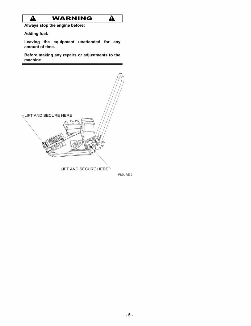
WARNINGAlways stop the engine before:
Adding fuel.
Leaving the equipment unattended for anyamount of time.
Before making any repairs or adjustments to themachine.
- 5 -
- 6 -
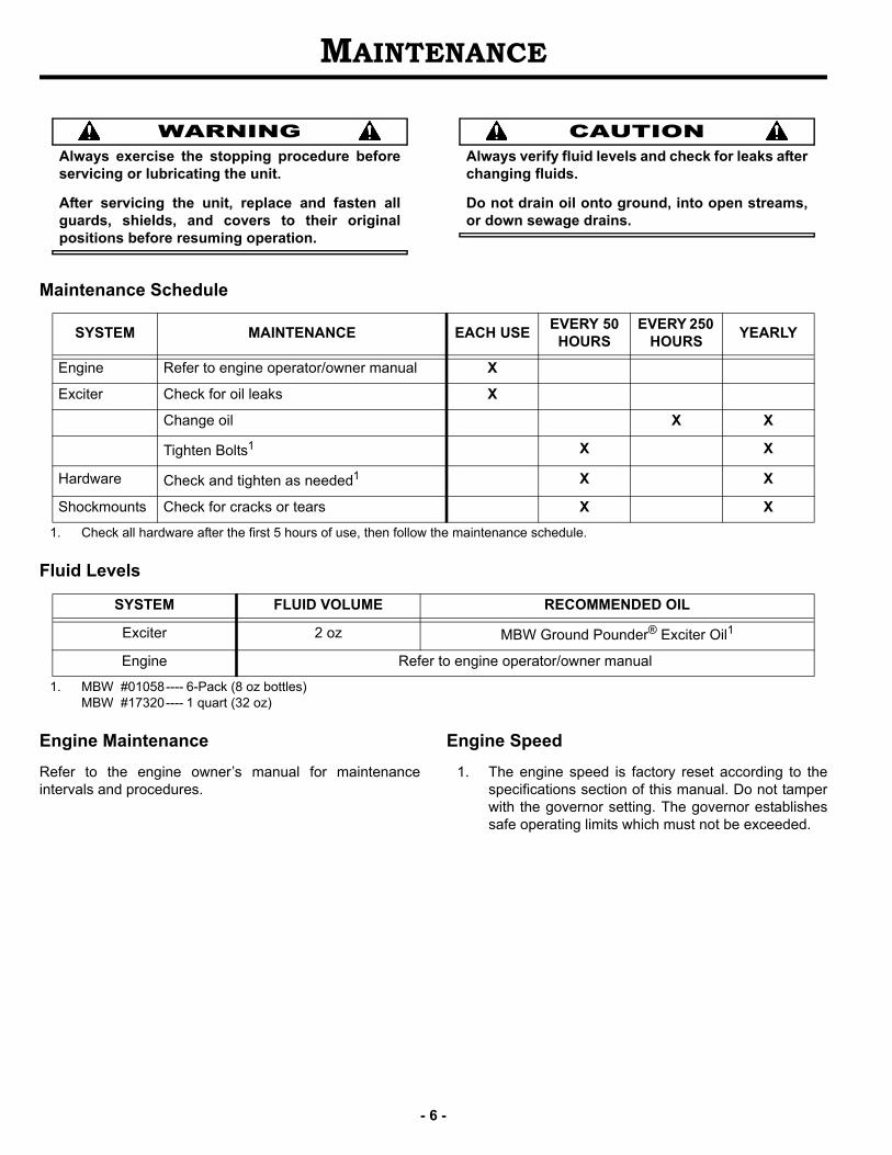
MAINTENANCE
WARNINGAlways exercise the stopping procedure beforeservicing or lubricating the unit.
After servicing the unit, replace and fasten allguards, shields, and covers to their originalpositions before resuming operation.
CAUTIONAlways verify fluid levels and check for leaks afterchanging fluids.
Do not drain oil onto ground, into open streams,or down sewage drains.
Maintenance Schedule
1. Check all hardware after the first 5 hours of use, then follow the maintenance schedule.
Fluid Levels
1. MBW #01058---- 6-Pack (8 oz bottles)MBW #17320---- 1 quart (32 oz)
Engine Maintenance
Refer to the engine owner’s manual for maintenanceintervals and procedures.
Engine Speed
1. The engine speed is factory reset according to thespecifications section of this manual. Do not tamperwith the governor setting. The governor establishessafe operating limits which must not be exceeded.
SYSTEM MAINTENANCE EACH USEEVERY 50
HOURSEVERY 250
HOURSYEARLY
Engine Refer to engine operator/owner manual X
Exciter Check for oil leaks X
Change oil X X
Tighten Bolts1 X X
Hardware Check and tighten as needed1 X X
Shockmounts Check for cracks or tears X X
SYSTEM FLUID VOLUME RECOMMENDED OIL
Exciter 2 oz MBW Ground Pounder® Exciter Oil1
Engine Refer to engine operator/owner manual
SERVICE
Assembly and disassembly should be performed by aservice technician who has been factory trained on MBWequipment. The unit should be clean and free of debris.Pressure washing before disassembly is recommended.
• Prior to assembly, wash all parts in a suitable cleaner orsolvent.
• Check moving parts for wear and failure. Refer to theReplacement section in this manual for tolerance andreplacement cycles.
• All shafts and housings should be oiled prior to pressingbearings. Also, ensure that the bearings are pressedsquare and are seated properly.
• All bearings should be replaced when rebuilding anyexciter or gearbox.
• All gaskets and seals should be replaced after anydisassembly.
Torque Chart
Service Tools
Engine Maintenance
1. Refer to engine Owner’s Manual for maintenanceschedule.
Engine RPM
1. Refer to the engine Owner’s Manual for procedure toset the operating and idle speed.
2. The engine operating speed should be set to theRPM listed in the Specifications section (Page 3).
3. The engine idle speed should not exceed 1800 RPM.If the idle speed is greater than 1800 RPM the clutchmay not disengage.
Changing Exciter Oil
Refer to EXCITER ASSEMBLY, page 12.
1. Allow machine to completely cool down beforeperforming any service or maintenance.
2. Clean debris from exciter, engine deck and baseplate.
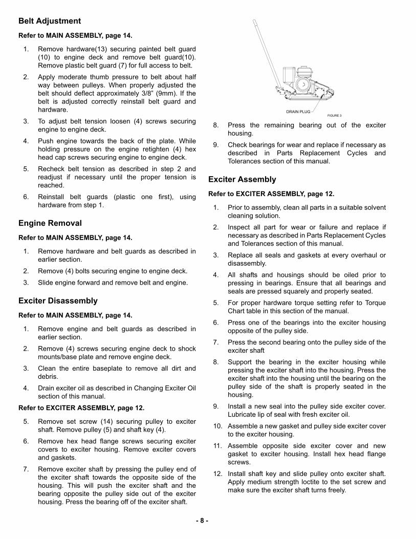
3. Remove drain plug (Figure 3), and tilt plate to theright so the oil drains from the exciter housing into apan.
4. After the oil is drained, tilt the plate to the left and wipeany excess oil from the plate. Do not get debris in theexciter drain hole.
5. Fill the exciter housing with MBW Inc. GrounderPounder® exciter oil according to the fluid levelspecified in the Maintenance section of this manual.DO NOT OVERFILL - over filling can result inexcessive temperatures in the exciter.
6. Apply pipe sealant to the plug and reinstall.
7. Discard the used oil and any contaminated debris ina proper container.
Cleanup
1. Remove dirt and debris from plate daily.
2. If repainting plate, be sure that all decals are masked.
3. Replace any decals that are damaged.
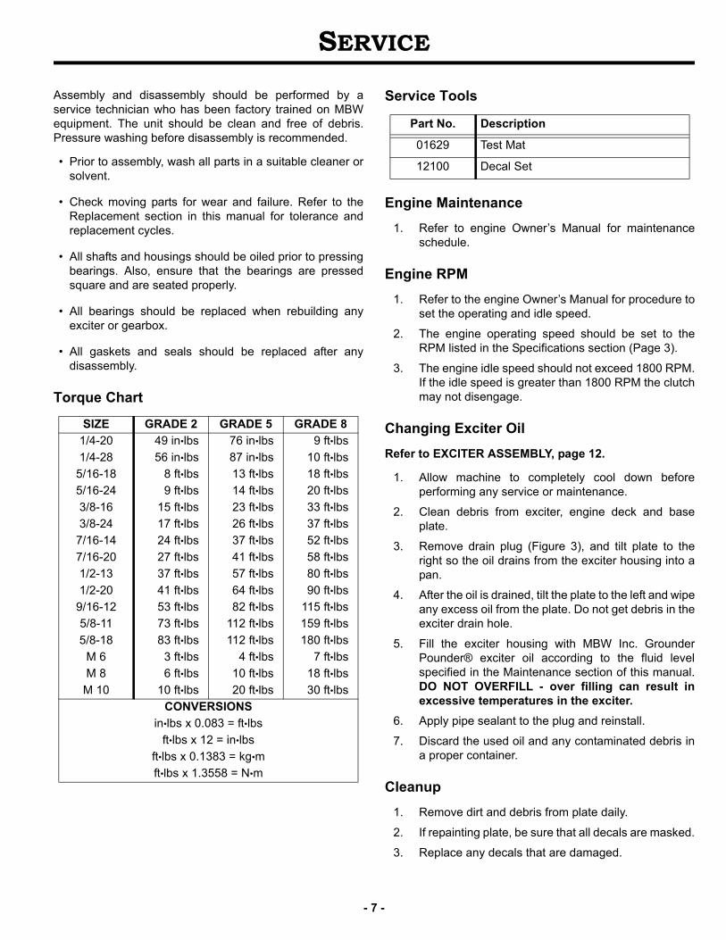
SIZE GRADE 2 GRADE 5 GRADE 8
1/4-20 49 in•lbs 76 in•lbs 9 ft•lbs
1/4-28 56 in•lbs 87 in•lbs 10 ft•lbs
5/16-18 8 ft•lbs 13 ft•lbs 18 ft•lbs
5/16-24 9 ft•lbs 14 ft•lbs 20 ft•lbs
3/8-16 15 ft•lbs 23 ft•lbs 33 ft•lbs
3/8-24 17 ft•lbs 26 ft•lbs 37 ft•lbs
7/16-14 24 ft•lbs 37 ft•lbs 52 ft•lbs
7/16-20 27 ft•lbs 41 ft•lbs 58 ft•lbs
1/2-13 37 ft•lbs 57 ft•lbs 80 ft•lbs
1/2-20 41 ft•lbs 64 ft•lbs 90 ft•lbs
9/16-12 53 ft•lbs 82 ft•lbs 115 ft•lbs
5/8-11 73 ft•lbs 112 ft•lbs 159 ft•lbs
5/8-18 83 ft•lbs 112 ft•lbs 180 ft•lbs
M 6 3 ft•lbs 4 ft•lbs 7 ft•lbs
M 8 6 ft•lbs 10 ft•lbs 18 ft•lbs
M 10 10 ft•lbs 20 ft•lbs 30 ft•lbs
CONVERSIONS
in•lbs x 0.083 = ft•lbs
ft•lbs x 12 = in•lbs
ft•lbs x 0.1383 = kg•m
ft•lbs x 1.3558 = N•m
Part No. Description
01629 Test Mat
12100 Decal Set
- 7 -
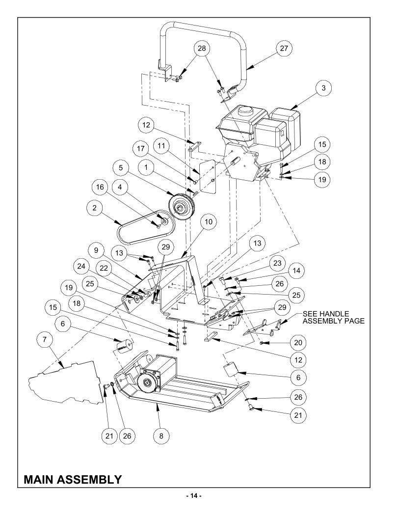
Belt Adjustment
Refer to MAIN ASSEMBLY, page 14.
1. Remove hardware(13) securing painted belt guard(10) to engine deck and remove belt guard(10).Remove plastic belt guard (7) for full access to belt.
2. Apply moderate thumb pressure to belt about halfway between pulleys. When properly adjusted thebelt should deflect approximately 3/8” (9mm). If thebelt is adjusted correctly reinstall belt guard andhardware.
3. To adjust belt tension loosen (4) screws securingengine to engine deck.
4. Push engine towards the back of the plate. Whileholding pressure on the engine retighten (4) hexhead cap screws securing engine to engine deck.
5. Recheck belt tension as described in step 2 andreadjust if necessary until the proper tension isreached.
6. Reinstall belt guards (plastic one first), usinghardware from step 1.
Engine Removal
Refer to MAIN ASSEMBLY, page 14.
1. Remove hardware and belt guards as described inearlier section.
2. Remove (4) bolts securing engine to engine deck.
3. Slide engine forward and remove belt and engine.
Exciter Disassembly
Refer to MAIN ASSEMBLY, page 14.
1. Remove engine and belt guards as described inearlier section.
2. Remove (4) screws securing engine deck to shockmounts/base plate and remove engine deck.
3. Clean the entire baseplate to remove all dirt anddebris.
4. Drain exciter oil as described in Changing Exciter Oilsection of this manual.
Refer to EXCITER ASSEMBLY, page 12.
5. Remove set screw (14) securing pulley to excitershaft. Remove pulley (5) and shaft key (4).
6. Remove hex head flange screws securing excitercovers to exciter housing. Remove exciter coversand gaskets.
7. Remove exciter shaft by pressing the pulley end ofthe exciter shaft towards the opposite side of thehousing. This will push the exciter shaft and thebearing opposite the pulley side out of the exciterhousing. Press the bearing off of the exciter shaft.
8. Press the remaining bearing out of the exciterhousing.
9. Check bearings for wear and replace if necessary asdescribed in Parts Replacement Cycles andTolerances section of this manual.
Exciter Assembly
Refer to EXCITER ASSEMBLY, page 12.
1. Prior to assembly, clean all parts in a suitable solventcleaning solution.
2. Inspect all part for wear or failure and replace ifnecessary as described in Parts Replacement Cyclesand Tolerances section of this manual.
3. Replace all seals and gaskets at every overhaul ordisassembly.
4. All shafts and housings should be oiled prior topressing in bearings. Ensure that all bearings andseals are pressed squarely and properly seated.
5. For proper hardware torque setting refer to TorqueChart table in this section of the manual.
6. Press one of the bearings into the exciter housingopposite of the pulley side.
7. Press the second bearing onto the pulley side of theexciter shaft
8. Support the bearing in the exciter housing whilepressing the exciter shaft into the housing. Press theexciter shaft into the housing until the bearing on thepulley side of the shaft is properly seated in thehousing.
9. Install a new seal into the pulley side exciter cover.Lubricate lip of seal with fresh exciter oil.
10. Assemble a new gasket and pulley side exciter coverto the exciter housing.
11. Assemble opposite side exciter cover and newgasket to exciter housing. Install hex head flangescrews.
12. Install shaft key and slide pulley onto exciter shaft.Apply medium strength loctite to the set screw andmake sure the exciter shaft turns freely.
- 8 -
13. Fill exciter housing with oil as described in ChangingExciter Oil section of this manual.
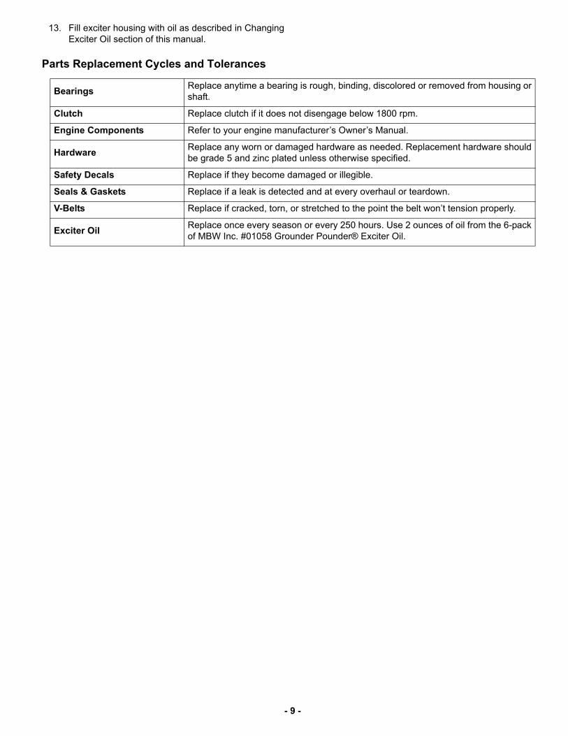
Parts Replacement Cycles and Tolerances
BearingsReplace anytime a bearing is rough, binding, discolored or removed from housing orshaft.
Clutch Replace clutch if it does not disengage below 1800 rpm.
Engine Components Refer to your engine manufacturer’s Owner’s Manual.
HardwareReplace any worn or damaged hardware as needed. Replacement hardware shouldbe grade 5 and zinc plated unless otherwise specified.
Safety Decals Replace if they become damaged or illegible.
Seals & Gaskets Replace if a leak is detected and at every overhaul or teardown.
V-Belts Replace if cracked, torn, or stretched to the point the belt won’t tension properly.
Exciter OilReplace once every season or every 250 hours. Use 2 ounces of oil from the 6-packof MBW Inc. #01058 Grounder Pounder® Exciter Oil.
- 9 -

- 10 -
MBW, Inc.250 Hartford Rd • PO Box 440Slinger, WI 53086-0440Phone: (262) 644-5234Fax: (262) 644-5169Email: [email protected]: www.mbw.com
MBW (UK) Ltd.Units 2 & 3 Cochrane StreetBolton BL3 6BN, EnglandPhone: 01204 387784Fax: 01204 387797
Contact Information
MBW FRANCE S.A.R.L.Z.A. d’Outreville11 rue Jean Baptiste Néron,60540 BORNELFRANCETeléfono: +33 (0) 3 44 07 15 96Fax: +33 (0) 3 44 07 41 28Correo electrónico: [email protected]
REPLACEMENT PARTS
The warranty is stated in this book on page 18. Failure toreturn the Warranty Registration Card renders the warrantynull and void.
MBW has established a network of reputable distributors/dealers with trained mechanics and full facilities formaintenance and rebuilding, and to carry an adequate partsstock in all areas of the country. Their sales engineers areavailable for professional consultation. If you cannot locatean MBW distributor in your area, contact MBW or one of ourSales Branches listed below.
When ordering replacement parts, be sure to have thefollowing information available:
• Model and Serial Number of machine when orderingMBW parts
• Model and Serial Number of engine when orderingengine parts
• Part Number, Description, and Quantity
• Company Name, Address, Zip Code, and PurchaseOrder Number
• Preferred method of shipping
REMEMBER - You own the best! If repairs are needed,use only MBW parts purchased from authorizedMBW distributors.
The unit’s serial number can be found in the followinglocations:
• The model/serial number decal is located on the back ofthe engine deck, behind the engine on the right side.
• The serial number is stamped on the top of the left rail ofthe base plate.
Write Model Number here
Write Serial Number here

- 11 -
This page intentionally left blank.
- 12 -
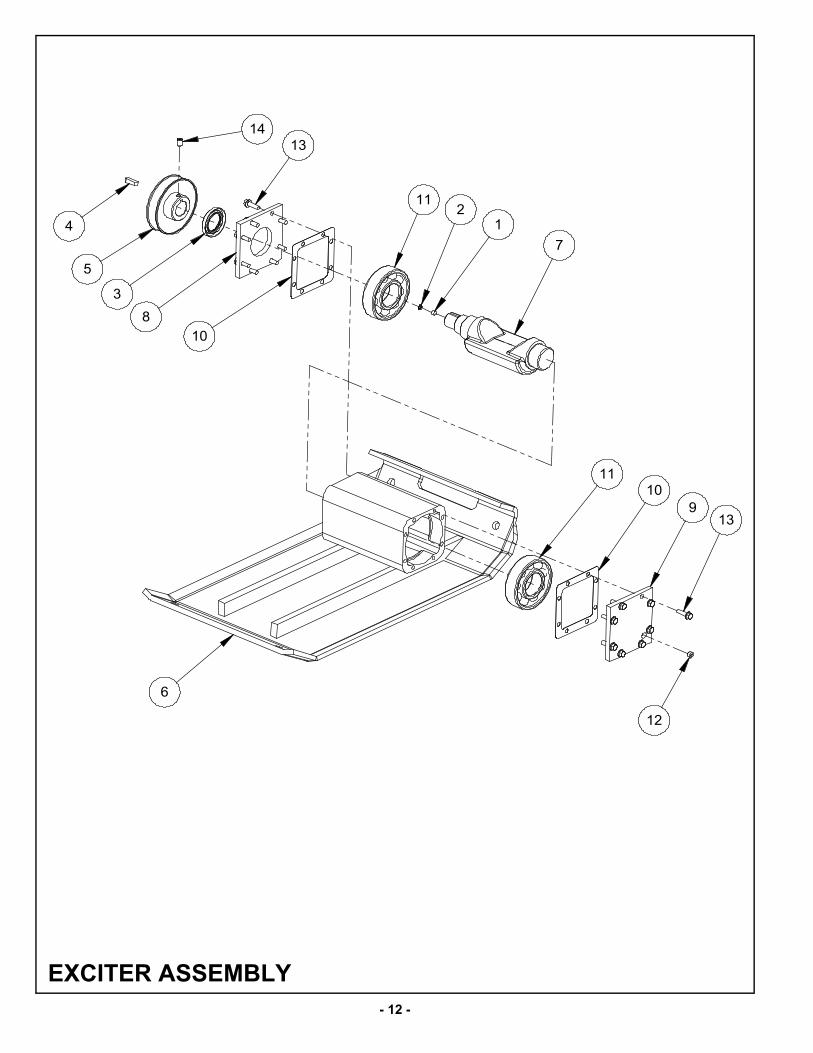
EXCITER ASSEMBLY
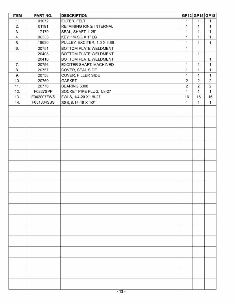
- 13 -
ITEM PART NO. DESCRIPTION GP12 GP15 GP18
1. 01072 FILTER, FELT 1 1 1
2. 01191 RETAINING RING, INTERNAL 1 1 1
3. 17179 SEAL, SHAFT, 1.25” 1 1 1
4. 06335 KEY, 1/4 SQ X 1” LG 1 1 1
5. 19630 PULLEY, EXCITER, 1.0 X 3.88 1 1 1
6. 20751 BOTTOM PLATE WELDMENT 1
20408 BOTTOM PLATE WELDMENT 1
20410 BOTTOM PLATE WELDMENT 1
7. 20756 EXCITER SHAFT, MACHINED 1 1 1
8. 20757 COVER, SEAL SIDE 1 1 1
9. 20758 COVER, FILLER SIDE 1 1 1
10. 20760 GASKET 2 2 2
11. 20776 BEARING 6308 2 2 2
12. F0227SPP SOCKET PIPE PLUG, 1/8-27 1 1 1
13. F042007FWS FWLS, 1/4-20 X 1/8-27 16 16 16
14. F051804SSS SSS, 5/16-18 X 1/2” 1 1 1
- 14 -
MAIN ASSEMBLY
- 15 -
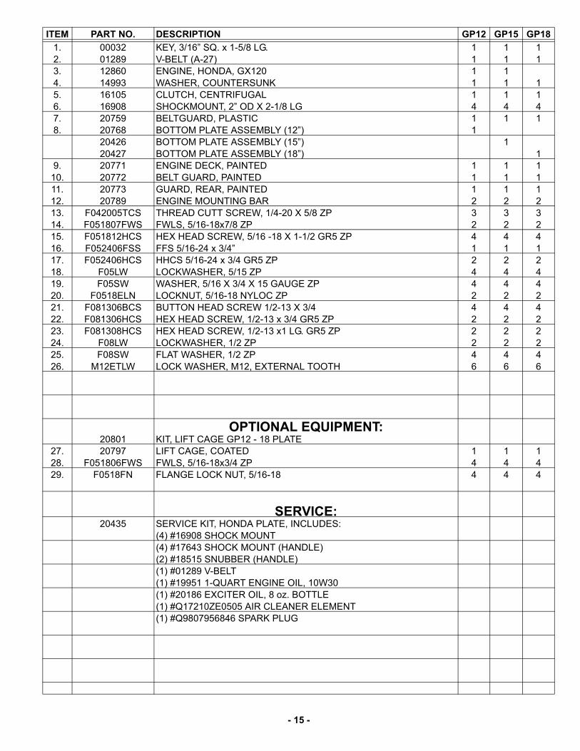
ITEM PART NO. DESCRIPTION GP12 GP15 GP18
1. 00032 KEY, 3/16” SQ. x 1-5/8 LG. 1 1 12. 01289 V-BELT (A-27) 1 1 13. 12860 ENGINE, HONDA, GX120 1 14. 14993 WASHER, COUNTERSUNK 1 1 15. 16105 CLUTCH, CENTRIFUGAL 1 1 16. 16908 SHOCKMOUNT, 2” OD X 2-1/8 LG 4 4 47. 20759 BELTGUARD, PLASTIC 1 1 18. 20768 BOTTOM PLATE ASSEMBLY (12”) 1
20426 BOTTOM PLATE ASSEMBLY (15”) 120427 BOTTOM PLATE ASSEMBLY (18”) 1
9. 20771 ENGINE DECK, PAINTED 1 1 110. 20772 BELT GUARD, PAINTED 1 1 111. 20773 GUARD, REAR, PAINTED 1 1 112. 20789 ENGINE MOUNTING BAR 2 2 213. F042005TCS THREAD CUTT SCREW, 1/4-20 X 5/8 ZP 3 3 314. F051807FWS FWLS, 5/16-18x7/8 ZP 2 2 215. F051812HCS HEX HEAD SCREW, 5/16 -18 X 1-1/2 GR5 ZP 4 4 416. F052406FSS FFS 5/16-24 x 3/4” 1 1 117. F052406HCS HHCS 5/16-24 x 3/4 GR5 ZP 2 2 218. F05LW LOCKWASHER, 5/15 ZP 4 4 419. F05SW WASHER, 5/16 X 3/4 X 15 GAUGE ZP 4 4 420. F0518ELN LOCKNUT, 5/16-18 NYLOC ZP 2 2 221. F081306BCS BUTTON HEAD SCREW 1/2-13 X 3/4 4 4 422. F081306HCS HEX HEAD SCREW, 1/2-13 x 3/4 GR5 ZP 2 2 223. F081308HCS HEX HEAD SCREW, 1/2-13 x1 LG. GR5 ZP 2 2 224. F08LW LOCKWASHER, 1/2 ZP 2 2 225. F08SW FLAT WASHER, 1/2 ZP 4 4 426. M12ETLW LOCK WASHER, M12, EXTERNAL TOOTH 6 6 6
OPTIONAL EQUIPMENT:20801 KIT, LIFT CAGE GP12 - 18 PLATE
27. 20797 LIFT CAGE, COATED 1 1 128. F051806FWS FWLS, 5/16-18x3/4 ZP 4 4 429. F0518FN FLANGE LOCK NUT, 5/16-18 4 4 4
SERVICE:20435 SERVICE KIT, HONDA PLATE, INCLUDES:
(4) #16908 SHOCK MOUNT(4) #17643 SHOCK MOUNT (HANDLE)(2) #18515 SNUBBER (HANDLE)(1) #01289 V-BELT(1) #19951 1-QUART ENGINE OIL, 10W30(1) #20186 EXCITER OIL, 8 oz. BOTTLE(1) #Q17210ZE0505 AIR CLEANER ELEMENT(1) #Q9807956846 SPARK PLUG
- 16 -
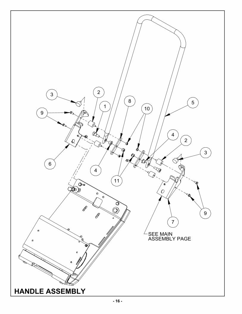
HANDLE ASSEMBLY
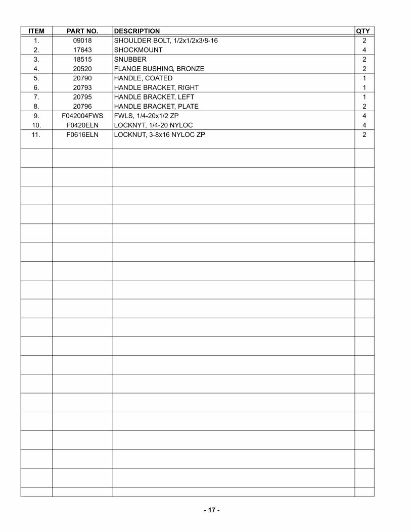
- 17 -
ITEM PART NO. DESCRIPTION QTY
1. 09018 SHOULDER BOLT, 1/2x1/2x3/8-16 2
2. 17643 SHOCKMOUNT 4
3. 18515 SNUBBER 2
4. 20520 FLANGE BUSHING, BRONZE 2
5. 20790 HANDLE, COATED 1
6. 20793 HANDLE BRACKET, RIGHT 1
7. 20795 HANDLE BRACKET, LEFT 1
8. 20796 HANDLE BRACKET, PLATE 2
9. F042004FWS FWLS, 1/4-20x1/2 ZP 4
10. F0420ELN LOCKNYT, 1/4-20 NYLOC 4
11. F0616ELN LOCKNUT, 3-8x16 NYLOC ZP 2
- 18 -
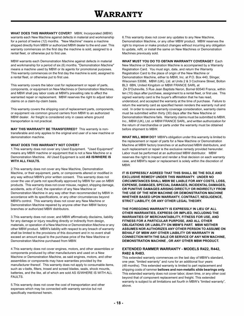
WARRANTY
WHAT DOES THIS WARRANTY COVER? MBW, Incorporated (MBW) warrants each New Machine against defects in material and workmanship for a period of twelve (12) months. "New Machine" means a machine shipped directly from MBW or authorized MBW dealer to the end user. This warranty commences on the first day the machine is sold, assigned to a rental fleet, or otherwise put to first use.
MBW warrants each Demonstration Machine against defects in material and workmanship for a period of six (6) months. "Demonstration Machine" means a machine used by MBW or its agents for promotional purposes. This warranty commences on the first day the machine is sold, assigned to a rental fleet, or otherwise put to first use.
This warranty covers the labor cost for replacement or repair of parts, components, or equipment on New Machines or Demonstration Machines, and MBW shall pay labor costs at MBW's prevailing rate to affect the warranted repair or replacement. MBW reserves the right to adjust labor claims on a claim-by-claim basis.
This warranty covers the shipping cost of replacement parts, components, or equipment via common ground carriers from MBW to an authorized MBW dealer. Air freight is considered only in cases where ground transportation is not practical.
MAY THIS WARRANTY BE TRANSFERRED? This warranty is non-transferable and only applies to the original end user of a new machine or demonstration machine.
WHAT DOES THIS WARRANTY NOT COVER?1.This warranty does not cover any Used Equipment. "Used Equipment" means any MBW machine or equipment that is not a New Machine or a Demonstration Machine. All Used Equipment is sold AS IS/WHERE IS WITH ALL FAULTS.
2.This warranty does not cover any New Machine, Demonstration Machine, or their equipment, parts, or components altered or modified in any way without MBW's prior written consent. This warranty does not cover the use of parts not specifically approved by MBW for use on MBW products. This warranty does not cover misuse, neglect, shipping damage, accidents, acts of God, the operation of any New Machine or Demonstration Machine in any way other than recommended by MBW in accordance with its specifications, or any other circumstances beyond MBW's control. This warranty does not cover any New Machine or Demonstration Machine repaired by anyone other than MBW factory branches or authorized MBW distributors.
3.This warranty does not cover, and MBW affirmatively disclaims, liability for any damage or injury resulting directly or indirectly from design, materials, or operation of a New Machine or Demonstration Machine or any other MBW product. MBW's liability with respect to any breach of warranty shall be limited to the provisions of this document and in no event shall exceed an amount equal to the purchase price of the New Machine or Demonstration Machine purchased from MBW.
4.This warranty does not cover engines, motors, and other assemblies or components produced by other manufacturers and used on a New Machine or Demonstration Machine, as said engines, motors, and other assemblies or components may have warranties provided by the manufacturer thereof. This warranty does not apply to consumable items, such as v-belts, filters, trowel and screed blades, seals, shock mounts, batteries, and the like, all of which are sold AS IS/WHERE IS WITH ALL FAULTS.
5.This warranty does not cover the cost of transportation and other expenses which may be connected with warranty service but not specifically mentioned herein.
6.This warranty does not cover any updates to any New Machine, Demonstration Machine, or any other MBW product. MBW reserves the right to improve or make product changes without incurring any obligation to update, refit, or install the same on New Machines or Demonstration Machines previously sold.
WHAT MUST YOU DO TO OBTAIN WARRANTY COVERAGE? Each New Machine or Demonstration Machine is accompanied by a Warranty Registration Card. You must sign, date, and return the Warranty Registration Card to the place of origin of the New Machine or Demonstration Machine, either to MBW, Inc. at P.O. Box 440, Slinger, Wisconsin 53086, MBW (UK), Ltd. at Units 2 & 3 Cochrane Street, Bolton BL3 6BN, United Kingdom or MBW FRANCE SARL at ZA D'Outreville, 5 Rue Jean Baptiste Neron, Bornel 60540 France, within ten (10) days after purchase, assignment to a rental fleet, or first use. This signed warranty card is the buyer's affirmation that he has read, understood, and accepted the warranty at the time of purchase. Failure to return the warranty card as specified herein renders the warranty null and void. In order to receive warranty coverage consideration, warranty claims must be submitted within thirty (30) days after the New Machine or Demonstration Machine fails. Warranty claims must be submitted to MBW, Inc., MBW (UK), Ltd. or MBW FRANCE SARL, and written authorization for the return of merchandise or parts under the warranty must be obtained before shipment to MBW.
WHAT WILL MBW DO? MBW's obligation under this warranty is limited to the replacement or repair of parts for a New Machine or Demonstration Machine at MBW factory branches or at authorized MBW distributors, and such replacement or repair is the exclusive remedy provided hereunder. Labor must be performed at an authorized MBW distributor. MBW reserves the right to inspect and render a final decision on each warranty case, and MBW's repair or replacement is solely within the discretion of MBW.
IT IS EXPRESSLY AGREED THAT THIS SHALL BE THE SOLE AND EXCLUSIVE REMEDY UNDER THIS WARRANTY. UNDER NO CIRCUMSTANCES SHALL MBW BE LIABLE FOR ANY COSTS, LOSS, EXPENSE, DAMAGES, SPECIAL DAMAGES, INCIDENTAL DAMAGES, OR PUNITIVE DAMAGES ARISING DIRECTLY OR INDIRECTLY FROM THE USE OF THE NEW MACHINE OR DEMONSTRATION MACHINE WHETHER BASED UPON WARRANTY, CONTRACT, NEGLIGENCE, STRICT LIABILITY, OR ANY OTHER LEGAL THEORY.
THE FOREGOING WARRANTY IS EXPRESSLY IN LIEU OF ALL OTHER WARRANTIES, EXPRESS OR IMPLIED, INCLUDING THE WARRANTIES OF MERCHANTABILITY, FITNESS FOR USE, AND FITNESS FOR A PARTICULAR PURPOSE, AND ALL OTHER OBLIGATIONS OR LIABILITY ON MBW'S PART. MBW NEITHER ASSUMES NOR AUTHORIZES ANY OTHER PERSON TO ASSUME ON BEHALF OF MBW ANY OTHER LIABILITY OR WARRANTY IN CONNECTION WITH THE SALE OR SERVICE OF ANY NEW MACHINE, DEMONSTRATION MACHINE , OR ANY OTHER MBW PRODUCT.
EXTENDED RAMMER WARRANTY - MODELS R422, R442, R482 & R483.This extended warranty commences on the last day of MBW’s standard, one year, “limited warranty” and runs for an additional four years(48 months). This extended warranty is limited to part replacement and shipping costs of rammer bellows and non-metallic slide bearings only. This extended warranty does not cover labor, down time, or any other cost beyond that of component replacement and freight. This extended warranty is subject to all limitations set fourth in MBW’s “limited warranty”, above.