gps basics - frequency electronics inc - precision …freqelec.com/gps_gnss/gps_basics_1-08.pdf ·...
TRANSCRIPT


2
Discussion OutlineDiscussion Outline
• The Basic GPS System
• GPS Signal Acquisition
• GPS Dilution of Precision
• Future Signal Structure
• The GPS Engine
• What “Was” SA?

3
The Basic GPS The Basic GPS SystemSystem

4
Historical Development Of Accurate ClocksHistorical Development Of Accurate Clocks
10,000
100
1
YEA
RS
TO L
OSE
1 S
ECO
ND
0.01
VARIATIONS IN THE EARTH’S ROTATION
ELECTRONICWRISTWATCH
MECHANICALWRISTWATCH
1000 1200 1400 1600 1800 2000YEAR
GA
LILE
O
LOSE 15 MINUTES PER DAY
NAVIGATION ACCURACY
= 170,000,000 MILES *
2 YEARS TO LOSE 1 SECOND
NAVIGATION ACCURACY
= 250 MILES *
QUARTZ CRYSTALS
LOSE 1 SECOND PER DAY
NAVIGATION ACCURACY = 186,000 MILES *
MARINE CHRONOMETERS
LOSE 3 MINUTES PER DAY
NAVIGATION ACCURACY
= 34,000,000 MILES *
MECHANICAL CLOCKS
* For 24-Hours of Navigation
100,000
100,000 YEARS TO LOSE 1 SECOND
NAVIGATION ACCURACY
= 30 FEET *
ATOMIC CLOCKS
CANDLE CLOCKS & WATER CLOCKS

5
Active and Passive RadioActive and Passive Radio--Navigation SystemsNavigation Systems
ACTIVE RADIO-NAVIGATIONt1
t2SIGNAL TRAVELS TWO WAYS
DISTANCE = C x 2t∆
PASSIVE RADIO-NAVIGATION
t1SIGNAL TRAVELS ONE WAY
DISTANCE = C x ∆t

6
11--Way 2D Electronic Ranging SystemWay 2D Electronic Ranging System
2-D Navigation: Perfect Clocks
• Great for Navy Ships; need only – 2D
• Not so great for Navy and USAF flyers –need 3D
Transmitter1
Transmitter2
The time is . . . The time is . . .
D1 = C*∆T1
D 2= C* ∆
T 2

7
Success of the 621B, 3Success of the 621B, 3--D Ranging Test D Ranging Test Program, 1968Program, 1968--71 lead to a space71 lead to a space--based GPSbased GPS
3-D Navigation: Perfect Clocks
• Now OK for Flyers and Vehicles alike
Transmitter(1)
Transmitter(2)
The time is . . .My location is …
Transmitter(3)
Ground-based Transmitters are put into Space
The time is . . .My location is …
The time is . . .My location is …

8
Space Borne 1Space Borne 1--Way 3D Ranging SystemWay 3D Ranging System
R1 = C(∆t1 + ∆T - τ1)
“...The time isMy position is...”
The Realistic GPS System
4 Equations — 4 Unknowns
R2 = C(∆t2 + ∆T- τ2)
R3 = C(∆t3 + ∆T - τ3)
R4 = C(∆t4 + ∆T - τ4)
1 0 0 0 1 1 1 1 1 0 1 0 0 0 1 1
1 1 1 0 0 0 1 1 1 0 1 0 0 0 1 1
←∆T→
RCVR Clock Error
∆t1
∆t2
∆t3
∆t4
Signal Travel Time
τ1
τ2
τ3
τ4
SV Clock ErrorSV C/A Gold Code
1 1 0 0 0 1 1 1 1 0 1 0 0 0 1 1
1 1 0 0 0 1 1 1 1 0 1 0 0 0 1 1
1 0 0 0 1 1 1 1 1 0 1 0 0 0 1 1
1 1 1 0 0 0 1 1 1 0 1 0 0 0 1 1
1 1 0 0 0 0 1 1 1 1 1 0 0 0 1 1
1 1 0 0 0 0 1 1 1 1 1 0 0 0 1 1
Sate
llite
Tim
e C
o des
Ma t
c hi n
g R
CVR
ie.
SV1
to S
V4
T
ime
Co d
e s

9
What is GPS?What is GPS?
• A space-based satellite navigation system developed by the DoD in the mid 70’s for military use, managed by a Joint Program Office (GPS-JPO) located at LAAFB, made up of the USAF, Navy, and other services,.
• A highly accurate 3-D navigation, positioning, and timing system, available 24 hours a day, 7 days a week, anywhere in the world.
• Has a clear (or coarse) acquisition signal (C/A-Code) to aid in the acquisition of the precision military signal (P-Code). Because the C/A-Code is in the clear, it serves as a civil navigation, positioning, and timing system, referred to as SPS (Standard Positioning Service), ~10m, 1σ, Spherical Error Probability (SEP).
• Also has a more accurate (precision) P-Code signal, available only to authorized cryptographic key users. When the P-Code is encrypted, it becomes the Y-Code. This is referred to as PPS (Precise Positioning Service), ~1m, 1 σ, SEP.
• SPS and PPS also provide an atomic time reference, accurate to ±100 ns of USNO - Master Clock, referenced to UTC (Universal Coordinated Time).
• The Satellite Constellation is controlled and maintained by the USAF from the Master Control Station (MCS) at Schriever AFB near Colorado Springs. The MCS is part of the Consolidated Space Operations Center (CSOC).
10
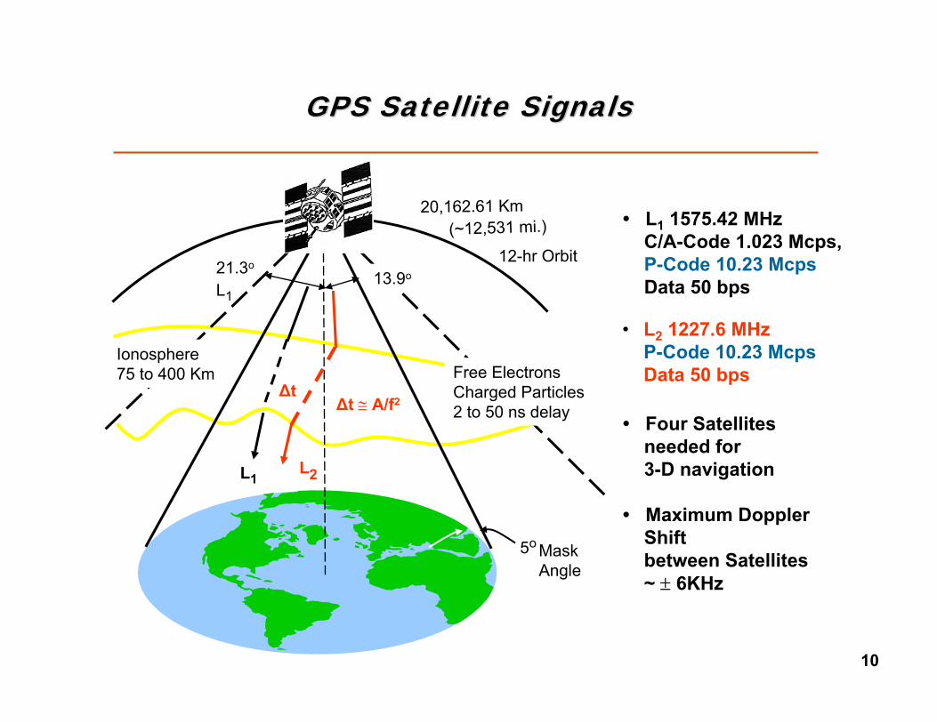
GPS Satellite SignalsGPS Satellite Signals
12-hr Orbit
20,162.61 Km(~12,531 mi.)
13.9o21.3o
L1
Ionosphere75 to 400 Km Free Electrons
Charged Particles2 to 50 ns delay
L1
MaskAngle
5o
∆t
L2
∆t ≅ A/f2
• L2 1227.6 MHz P-Code 10.23 McpsData 50 bps
• L1 1575.42 MHz C/A-Code 1.023 Mcps, P-Code 10.23 McpsData 50 bps
• Four Satellitesneeded for3-D navigation
• Maximum DopplerShift between Satellites ~ ± 6KHz

11
Antenna Pattern
0°5°
20°
40°
60°90°80°
GPS Antenna:12 Element
L-Band Helical Phased Array (On-axis view)
Rec
eive
d P
ower
at 3
dB
Line
arly
Pol
ariz
ed A
nt. (
dBw
)
Horizon
5 20 40 60 80 90
Zenith
User Elevation Angle (deg)
Received Power vs. SV Elevation Angle
L1-C/A
GPS Signal RealitiesGPS Signal Realities
-158
-164
-160*
-162
-166
-165
-161
-159
-163
L2-P(Y)
L1-P(Y)
~1x10-16 watts*
-158.5 dBw
-161.5 dBw
-160.0 dBw
-164.5 dBw
L2C

12
Satellite ConstellationSatellite Constellation
• All near perfect circular orbits• 21 to 24 Satellites required for
24 x 7 coverage
30 GPS Satellites in Operation at present

13
GPS Satellite (Block II, IIA) GPS Satellite (Block II, IIA) –– Rockwell (RI)Rockwell (RI)
All Have Been Launched
Major Characteristics
Launch mass 3,675 lb.
On-Orbit mass 1,862 lb.
Solar Array 1,000 Watts
Design Life 7.5 years
Consumables 10 years
Clocks (2) Rb, (2) Cs
RI-Efr FTS

14
GPS Satellite (Block IIR) GPS Satellite (Block IIR) –– LockheedLockheed--MartinMartin
Major Characteristics
Launch mass 4,480 lb.
On-Orbit mass 2,210 lb.
Solar Array 1,100 Watts
Design Life 7.5 years
Consumables 10 years
Clocks (3) Rb
EG&G**now Perkin-Elmer
In Launching Phase

15
GPS Satellite (Block IIF) GPS Satellite (Block IIF) –– Boeing*Boeing*
Major Characteristics
Launch mass 4,634 lb.
On-Orbit mass ~2,400 lb.
Solar Array 1,560 Watts
Design Life 15 years
Consumables 15 years
Clocks (2) Rb, (1) Cs
EG&G* FTS***Now Perkin-Elmer
**Now Symmetricom
In Launching Phase
* Was Rockwell International

16
ComparisonComparison of GPS and GLONASSof GPS and GLONASS
Parameter GLONASS GPS Ephemeris information presentation method
9 parameters of s/c motion in the geocentric rectangular rotated coordinate system
Interpolation coefficients of satellite orbits
Geodesic coordinate system SGS 85 WGS 84 Referencing of the ranging signal phases
To the timer of GLONASS system
To the timer of GPS system
System time corrections relative to the Universal Coordinated Time (UTC)
UTC (SU) UTC (USNO)
Duration of the almanac transmission
2.5 min 12.5 min
Number of satellites in the full operational system
21 + 3 spares 21 + 3 spares
Number of orbital planes 3 6 Inclination 64.8° 55° Orbit altitude 19100 km 20180 km Orbital period 11 h 15 min 12 h Satellite signal division method
Frequency Division Code Division
Frequency band allocated (L1) 1602.5625-1615.5 ± 0.5 MHz
1575.42 ± 1MHz
Type of ranging code PRN-sequence of maximal length
Gold Code
Number of code elements 511 1023 Timing frequency of code (C/A)
0.511 MHz 1.023 MHz
Crosstalk level between two neighboring channels
-48 dB -21.6 dB
Synchrocode repetition period 2 sec 6 sec Symbol number in the synchrocode
30 8
GLONASS
GPS
17
GPS Signal GPS Signal StructureStructure

18
The GPS Carrier Modulation SignalsThe GPS Carrier Modulation Signals
Carriers (L1/L2)
(SA) Degrad.Now set to
Zero Frequency Dither(On All Above Signals)
1540 Cycles per C/A-Chip
Transmitted in Phase Quadrature (90° Out of Phase)
C/A Code
P Code
Phase Shift Keying (PSK) Modulation
Data (L1/L2) 50 BPS
(AS) EncryptionP becomes (Y) Y-Code
P- Code (L1/L2)10.23 MCPS
C/A - Code (L1) 1.023 MCPS

19
New New MM--Code Code (Future)(Future) MMMMMMMM
New New L2CL2C
GPS Signal StructureGPS Signal Structure
1563.42 MHz
1587.42 MHz
C/A
P(Y)
10.23 MHz
10.23 MHz
1.023 MHz
1.023 MHz
Spread Spectrum Signal, ~30 dB below the receiver ambient noise level
(Said to represent energy of a 25 watt light bulb at 11,000 miles distance)
L1
1575.42 MHz
1227.6 MHz
1215.6 MHz
1239.6 MHz
10.23 MHz
10.23 MHz
P(Y)
L2
20
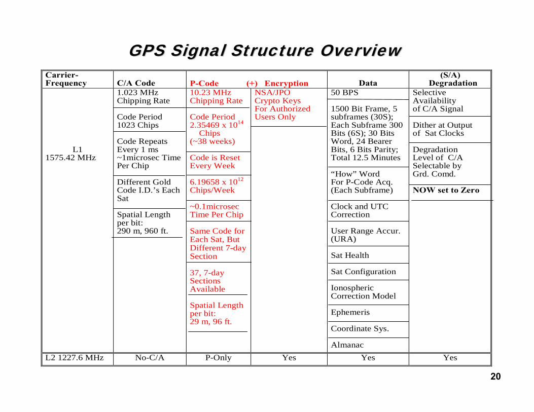
GPS Signal Structure OverviewGPS Signal Structure OverviewCarrier-Frequency
C/A Code
P-Code (+) Encryption
Data
(S/A) Degradation
L1 1575.42 MHz
1.023 MHz Chipping Rate
Code Period 1023 Chips
Code Repeats Every 1 ms ~1microsec Time Per Chip
Different Gold Code I.D.’s Each Sat Spatial Length per bit: 290 m, 960 ft.
10.23 MHz Chipping Rate
Code Period 2.35469 x 10¹⁴
Chips (~38 weeks) Code is Reset Every Week 6.19658 x 10¹² Chips/Week ~0.1microsec Time Per Chip
Same Code for Each Sat, But Different 7-day Section
37, 7-day Sections Available Spatial Length per bit: 29 m, 96 ft.
NSA/JPO Crypto Keys For Authorized Users Only
50 BPS
1500 Bit Frame, 5 subframes (30S); Each Subframe 300 Bits (6S); 30 Bits Word, 24 Bearer Bits, 6 Bits Parity; Total 12.5 Minutes
“How” Word For P-Code Acq. (Each Subframe)
Clock and UTC Correction
User Range Accur. (URA)
Sat Health
Sat Configuration
Ionospheric Correction Model
Ephemeris
Coordinate Sys.
Almanac
Selective Availability of C/A Signal
Dither at Output of Sat Clocks
Degradation Level of C/A Selectable by Grd. Comd.
NOW set to Zero
L2 1227.6 MHz No-C/A P-Only Yes Yes Yes

21
GPS Data Message GPS Data Message -- 50 Bits Per Second50 Bits Per Second
Subframe
Bit No. 0
Subframe
Subframe
Subframe
30 60 300
300 330 360 600
Telemetry Words
Handover Words Clock Correction
Ephemeris
Ephemeris
Handover Words
Telemetry Words
Handover Words
Telemetry Words
Handover Words
Telemetry Words
Handover Words
Telemetry Words
Message (Changes Through 25 Frames)(Multiplex)
6 Sec
12 Sec
18 Sec
24 Sec
30 Sec**Almanac/Health Status
(Changes Through 25 Frames, Then Repeats)*Subframe (Multiplex)
600 630 660
900 930 960
900
1200
15001200 1230 1260
* Format of frame twenty-five changes
** 12.5 minutes before the entire message repeats

22
GPS Data Message FormatGPS Data Message Format
Basic message unit is one frame (1500 bits long)
1 frame = 5 subframes
1 subframe = 10 words
1 word = 30 bits
One MASTER FRAME includes all 25 pages of subframes4 and 5 = 37,500 bits taking 12.5 minutes to transmit
1 2 3
4 5
30 Sec
1 2 3 4 5 6 7 8 9 10
6 Sec
0.6 Sec
0.02 Sec
Subframes 4 and 5 have 25 pages

23
Basic Spread Spectrum ConceptBasic Spread Spectrum Concept
Conventional
Digital Data
Digital MOD
Carrier Generator
Oscillator(Poor Osc OK)
A
f
Signal Data
20 KHz
Ambient Noise
Spectral Density in i.e. 20 KHz
20 KHzL-Band
RF Sec
De-MOD
20 KHz Data
Remove Carrier
Oscillator
(Poor Osc OK)
Spread Spectrum
Digital Data
Digital MOD
Carrier Generator
Oscillator
(Need Prec. Osc.)
A
20 KHzL-Band
Code Generator
f
Ambient Noise
Same Spectral Density; i.e. over 20 MHz10 MHz
RF Sec
De-MOD
20 KHz Data
Oscillator Code Generator
(Need Prec. Osc.)
Remove Carrier Remove PN-MOD

24
C/AC/A--Code with Data Stream SuperimposedCode with Data Stream Superimposed
~1Mbit/Sec C/A Code
1 1 1 1 10 0 0 0 0 1 1 1 1 10 0 0 0 0 0 1 1 1 1 10 0 1 1 0 0 1 11 1 1 10 0
Note: There are ~20,000 C/A Bits
for one Data Stream Bit
1 10 0
1 1 1 1 10 0 0 0 0 11 1 11000 00 1 1 1 10 0 0 1 11 0 1 1 0 0 10 1 0 0
Note: The Data Stream is superimposed on both the ~1Mbit/Sec C/A-Code and the ~10 Mbit/Sec P-Code
C/A Code + Data Stream
50 bit/Sec Data Stream
Modulo-2 Addition C/A + Data
0 + 0 = 01 + 0 = 10 + 1 = 11 + 1 = 0

25
GPS Signal Acquisition

26Other GNSS Systems
Europe’s Galileo
Military SAASM
Civil and Military Signal RelationshipsCivil and Military Signal Relationships
GPS Sats
Civil C/A Code Mod. + Data + <100ns Clock
L1
C/A PNT
1023 Chips; repeat each ms
Data + 1PPS
L1 C/A, P(Y)+ 50 bps
Mil P(Y) Code Mod. + Data
L2 P(Y)+ 50 bps
L2
Real-time Ionospheric Corrections
P(Y) PNT
Acquisition Aid (<100ns Clock)
Mil P(Y) Code Mod. + Data
Crypto Key
~6.2 x 10¹² Chips; repeat each week
Partial Ionos. Corrections (Model only)
Typical GPS Receiver

27
The Autocorrelation FunctionThe Autocorrelation FunctionSatellite
C/A-Code
User Set matching C/A-Code
1-1-1
1-1 -1
11-1 -1 -1
1 1-1 -1
11 1-1
-1 -1 -1 -11 1 1 1 1
-1
Autocorrelation Function US
N
US
XXN
•∑=
1In the case above:
( )( ) ( )( ) ( )( ) ( )( ) ( )( ) ( )( ) ( )( ) ( )( ) ( )( ) ( )( )11111111111111111111101 10
−++−−+−++−−+−+−+−+−−=•∑=US
US XX
( ) 01111111111101
=−++−++−−−+=
Satellite
User Set
( )( ) ( )( ) ( )( ) ( )( ) ( )( ) ( )( ) ( )( ) ( )( ) ( )( ) ( )( )11111111111111111111101 10
++−−+−−++−−+++−−+−−=•∑=US
US XX
( ) 11111111111101
=+++++++++=
1-1-1
1-1 -1
11-1 -1 -1
1 1-1 -1
1 1 1-1
-1 -1 -1 -11 1 1 1 1
-1
Autocorrelation Value
-1
0
+1
1 2 3 4Cycle
Lock On
Shifting 3 bits (time) to the right gives:

28
Acquiring the Clear Civil C/A SignalAcquiring the Clear Civil C/A Signal
Satellite
User-Set
C/A Sequence from User-Set
C/A Sequence from Satellite
CB*Autocorrelation
+1
0
Best Match
1/1000 Sec
1/1,000,000 Sec
1 1 1 1 1 1 1 1 10 0 0 0 0 0 0
1 1 1 1 1 1 1 1 10 0 0 0 0 0 0
1 1 1 1 1 1 1 1 10 0 0 0 0 0 0
*CB ~ internal clock time error
from RCVR Oscillator aging
∆t1
R1
R2
R3
R4
= C∆t1
= C∆t2
= C∆t3
= C∆t4
Pseudo Ranges: Position Equations:
UX UY UZ CB
(X2 - )2 + (Y2 - )2 + (Z2 - )2 = (R2 - )2UX UY UZ CB
UX UY UZ CB
(X4 - )2 + (Y4 - )2 + (Z4 - )2 = (R4 - )2UX UY UZ CB
(X1 - )2 + (Y1 - )2 + (Z1 - )2 = (R1 - )2
(X3 - )2 + (Y3 - )2 + (Z3 - )2 = (R3 - )2

29
Acquiring the Military P(Y)Acquiring the Military P(Y)--Code SignalCode Signal
User-Set Matches the C/A Code
1 1 1 1 1 1 10 0 00 0 0
1 1 1 1 1 1 10 0 00 0 0
Satellite C/A Code
∆t1 ∆t1User Set C/A Code
1
0
Autocorrelation
Strips off the Data - “How” Word Gives Address of P-Code Match
11 1 100 0 0 1 10
11 1 100 0 0 1 10
∆t1∆t1
User Set P Code
Satellite P CodeTLM
WordHow Word Clock Correction
R1
R2
R3
R4
= C∆t1
= C∆t2
= C∆t3
= C∆t4
Pseudo Ranges: Position Equations:
*CB ~ 1/100 Sec for one week of user-set drift
UX UY UZ CB
(X2 - )2 + (Y2 - )2 + (Z2 - )2 = (R2 - )2UX UY UZ CB
UX UY UZ CB
(X4 - )2 + (Y4 - )2 + (Z4 - )2 = (R4 - )2UX UY UZ CB
(X1 - )2 + (Y1 - )2 + (Z1 - )2 = (R1 - )2
(X3 - )2 + (Y3 - )2 + (Z3 - )2 = (R3 - )2

30
Obtaining the Velocity ComponentsObtaining the Velocity Components
User-Set Locks onto Carrier to Obtain Doppler Shift
Satellite Carrier Wave
User Set Carrier Wave
Count and Difference to Get
∆ Ø / Ø
Time
Time
User-Set Performs the Navigation Solution for Velocity
Range Rates: Velocity Equations:
Where = Frequency Drift in the User-Set ClockBC&
= ∆ Ø1 / Ø1 C1R&= ∆ Ø2 / Ø2 C2R&
Ø
Ø
3R& = ∆ Ø3 / Ø3 C
4R& = ∆ Ø4 / Ø4 C
( )( ) ( )( ) ( )( ) ( )+=−−+−−+−− 111Z11Y11X1 RRZUZYUYXUX &&&& XU& BC&YU& ZU&( )( ) ( )( ) ( )( ) ( )+=−−+−−+−− 222Z22Y22X2 RRZUZYUYXUX &&&& XU& BC&YU& ZU&( )( ) ( )( ) ( )( ) ( )+=−−+−−+−− 333Z33Y33X3 RRZUZYUYXUX &&&& XU& BC&YU& ZU&( )( ) ( )( ) ( )( ) ( )+=−−+−−+−− 444Z44Y44X4 RRZUZYUYXUX &&&& XU& BC&YU& ZU&

31
Rough example of a typical search processRough example of a typical search process32 Bins(+) 3,200 Hz
Freq. Error
(+) 1,575 Hz
≈ (+)Freq. Error
(+) 100Hz(+) Time Error(-) Time Error
(+) 0.5 Sec
± 0.5 Sec ÷ 42 µs/Bin= ~23,810 Binsx 15 ms Dwell Time= ~360 Sec(~6 minutes)
≈ ≈
(-) 100Hz
(-) 0.5 Sec
Freq. Error
(-) 1,575 Hz
(-) 42 µs
(+) 42µs
≈0
Time Error
~11,905 Bins
~6 Min.Search Time
(-)Freq. Error
32 Bins(-) 3,200 Hz
More than 1.5 Million Bins will have been searched
Assuming a ± 0.5 sec time error and a ± 1 ppm RCVR clock
~ 420 Chipsx 64, 100 Hzbins
etc -42µs -42 -42 +42+42 +42µs etc

32
Elements Involved in GPS AcquisitionElements Involved in GPS Acquisition
• Jamming or ambient noise level• Signal blocking (canyons, buildings, trees, etc.)• Civil (C/A) signal availability (level of SA, if on)• Number of satellites in view• Position of satellites (GDOP)• Motion (and frequency of change) of GPS platform• Velocity (Doppler) of GPS platform• Vibration and Shock forces• Initialization Parameters (Time and Position)
• Acquisition sequence with C/A and P-Codes• Signal Processing Architecture and Mfr’s SW savvy• Type of Key, if using PPS receiver• Age of the ephemeris and Almanac• Averaging Time of PVT Solutions • RCVR noise level • RCVR oscillator spec
External Factors
Internal Factors (RCVR)

33
GPS Dilution of GPS Dilution of PrecisionPrecision

34
Satellite Geometry and GDOPSatellite Geometry and GDOP
mp σDOPσ ∗=
Positioning Accuracy (X, Y, Z)
Geometry (Dilution of Precision)
Measurement Accuracy (UERE)
Good GDOP(ideal case)
• One satellite overhead
• 3 on horizon, 120° apart in azimuth
Error Ellipsoid
Elongated
Poor GDOPSatellites bunched
together

35
What is Geometric Delusion of Precision (GDOP)?What is Geometric Delusion of Precision (GDOP)?
Two Transmitters Near Side by Side Two Transmitters Near 180° Apart
Two Transmitters 90° Apart
X
Y
Range
Uncertainty
∆RR1 R2
Range Uncertainty
∆R
X
Y
R1 R2
Y
X
Range Uncertainty
∆R
R2R1
))((2~ RX
YX
∆
∆=∆
Optimum

36
Future Signal Future Signal StructureStructure
37
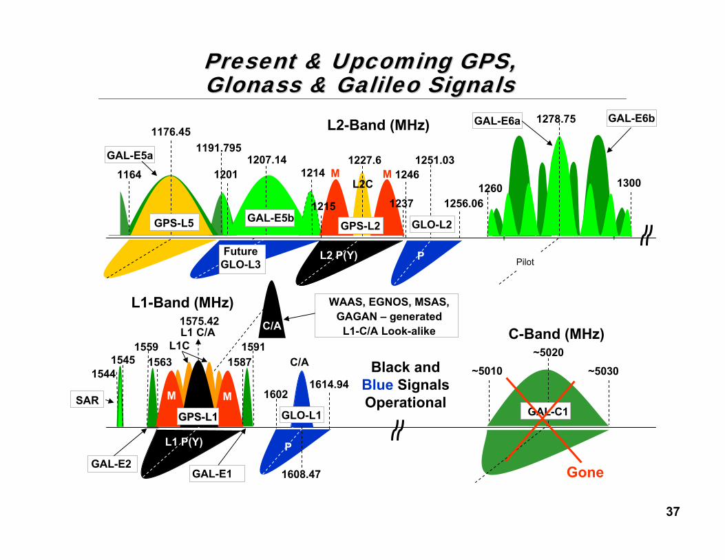
L1C1559 1591
GAL-E1GAL-E2
GAL-E6b
GLO-L2
P
Black and Blue Signals Operational
L2-Band (MHz)
L1-Band (MHz)
P
C/A
GLO-L1
1587
GAL-E5a 1207.141214
1176.45
1164
GPS-L5
L2C
C-Band (MHz)~5020
GAL-C1
~5030~5010
Gone
P
GAL-E6a
13001260
1278.75
Pilot
1563
L2 P(Y)
1575.42
L1 P(Y)
L1 C/A
WAAS, EGNOS, MSAS, GAGAN – generated
L1-C/A Look-alikeC/A
MM
GPS-L2GAL-E5b
1215 1237
1191.7951251.03
1256.06
1246
16021614.94
1608.47
1227.61201
GPSGPS--L1L1
MM
15451544
SAR
Future GLO-L3
Present & Upcoming GPS, Present & Upcoming GPS, Glonass & Galileo SignalsGlonass & Galileo Signals

38
The GPS Sync The GPS Sync EngineEngine
39
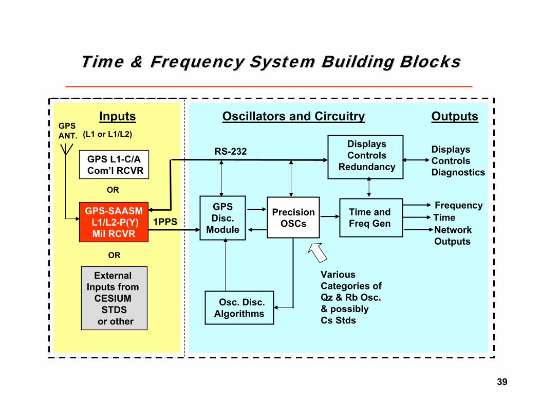
Time & Frequency SystemTime & Frequency System Building BlocksBuilding Blocks
FrequencyTimeNetworkOutputs
Outputs
Displays ControlsDiagnostics
GPS-SAASML1/L2-P(Y)Mil RCVR
GPSANT.
GPS L1-C/ACom’l RCVR
Inputs
External Inputs from
CESIUM STDS
or other
OR
OR
1PPSPrecision
OSCsTime and Freq Gen
GPSDisc.
Module
Osc. Disc.Algorithms
Displays Controls
Redundancy
Oscillators and Circuitry
VariousCategories of Qz & Rb Osc.& possiblyCs Stds
RS-232
(L1 or L1/L2)

40
Typical GPS Sync Engine DetailsTypical GPS Sync Engine Details
OSC Modeling- Temp-K- Aging- etc.
µ P & Logic
TIC SyncLogic
GPS DataAveraged & Voted1 PPS
(Ref. Sig.)
Fly WheelOscillator
10MHzRef.
Synth.Optional
OUTPUTSSat. Info/Diagnostics
1 PPS,etc.
10 MHz, etc.- Sine- Sq. W- TTL
Adj. OSC. (Analog or
Digital)
OSC. Options
TCXO no-holdover average performanceOCXO good holdover good performanceDOCXO better holdover better performanceRubidium best holdover best performance
1PPSs from
Satellites
GPS RCVR
QzOSC

41
USNO SAASM CalibrationAll 4 Days
-40
-35
-30
-25
-20
-15
-10
-5
0
5
1 533 1065 1597 2129 2661 3193 3725 4257 4789 5321 5853 6385 6917 7449 7981 8513
Seconds X10
Nan
osec
onds
Day 1Day 2Day 3Day 4
UTCTotal
Mean -14.294 -15.942 -17.365 -19.643 -16.854Std Dev 5.183 4.194 4.749 4.647 5.100RMS 15.204 16.483 18.003 20.185 17.608
USNO SAASM Calibration DataTime Error (ns)
TimeTime
Typical Time Error to UTC Typical Time Error to UTC –– locked to GPS locked to GPS ((T/F System, 4T/F System, 4--Day Test)Day Test)

42
Typical Time Error to UTC Typical Time Error to UTC –– locked to GPS locked to GPS
ns
ns
Time; < 20ns rms, 50ns Peak to UTC

43
7 Days 7 Days Rb Oscillator Rb Oscillator (no modeling)(no modeling)
~4 to 6 us~4 to 6 us
Mic
rose
cond
sM
icro
seco
nds
1 Day 1 Day Qz Oscillator Qz Oscillator (with modeling)(with modeling)
~7 to 10 us~7 to 10 us
TimeTime
Typical Holdover Time Error to UTC Typical Holdover Time Error to UTC –– unlocked unlocked ((T/F System)T/F System)

44
51970.0 51971.0 51972.0 51973.0 51974.0-11-1.0x10
-12-5.0x10
0
-125.0x10
-111.0x10
Frac
tiona
l Fre
quen
cy
MJD
Long Term: ZYFER RCVR Vs. Ch 1Frequency Data
07-19-2001 16:48:31Tau = 300 Sec Number of Points = 1008
FreqOffset Quad Fit: x = a + bt + ct^2 Drift Quad Fit: x = a + bt + ct^2
Frequency Offset = 5.8657E-14 Drift = 6.8707E-14 per day Phase Offset = -1.84549E+1 Sec
3.5 days
FrequencyFrequency
Typical Frequency Error to UTC Typical Frequency Error to UTC –– locked to GPS locked to GPS ((T/F System)T/F System)

45
~2 to 5E~2 to 5E--1111
7 Days 7 Days Rb Oscillator Rb Oscillator (mo modeling)(mo modeling)
FrequencyFrequency
Typical Holdover Freq. Error to UTC Typical Holdover Freq. Error to UTC –– unlocked unlocked ((T/F System)T/F System)
1 Day 1 Day Qz Oscillator Qz Oscillator (with modeling)(with modeling)
~1 to 2E~1 to 2E--1010

46
~1.4E-13
~1.4E-14
Worst - Best GPS Satellite Clockperformance
Ground & in Space MEASURABLE
Worst - Best GPS Satellite Clock
performance Ground & in Space, NOT
MEASURABLE from Space
Com’l and Mil Signal Performance from GPS
RCV R vs. UTC
GPS RCV R Short-Term performance mainly due to 3 ns+ multi-path type noise and ‘RCVR to Osc’
servo loop noise
Hump mainly due to ‘RCV R to Osc’ servo loop time constant, ∆
temp, multi-path noise, and ionosphere ∆’s
a 5 MHz Low Noise Module Performance
locked to GPS
45
Frequency Stability Frequency Stability –– GPS disciplined OscillatorGPS disciplined Oscillator

47
Ref zeroRef zero
Ref zeroRef zero
Typical Freq. & Time Accuracy vs. WarmTypical Freq. & Time Accuracy vs. Warm--up Time up Time
Frequency
Time
Rb Lock at ~3 min; Freq.
Acc. ~1E-9
GPS Lock at ~4.5 min; Freq.
Acc. ~2E-10
GPS discipline at ~13 min; Freq. Acc.
~1E-11
Rb Resonance Search Mode,
~ ±1E-9

48
What What ““ isis”” (was)(was) SA?SA?

49
SA OriginSA Origin
• The initial GPS Block-I Satellites were launched in the late ’70’s early ’80’s
– These did not have SA capability
• After testing the initially deployed satellite constellation, itwas realized that the “in-the-clear” C/A signal PVT Solutions (Position, Velocity, and Time) were far more accurate than expected (20 to 30m vs. expected >100m)
– Hence, the need to protect our forces against the use of C/A by our adversaries during times of conflict
– All GPS satellites thereafter had SA capability and activated to ~100m, 340ns, 3σStarting 1983 (per Federal Radio Navigation Plan)

50
What is SA?What is SA?
• A deliberate signal distortion affecting the accuracy of the C/A-Code derived PVT
• When activated, the effects are worldwide and cannot easily be implemented in selected geographic areas
• The distortion is generated by each satellite and the magnitude of the distortion is set by a ground station uplink command.
• SA basically consists of:
– SA induced “Range” uncertainty of C/A-derived PVT solution
– Range distortion can be set from zero (no SA effect) to 1000s of meters and many microseconds

51
Simplified GPS Satellite Navigation PackageSimplified GPS Satellite Navigation Package
AtomicOsc.
S.A.DitherSynth
Uplink Control
Uplink Control
Rb or Cs10.23 Hz
Mult.
CarrierSynth.
(L1) 1575.42 MHzHPA
(L2) 1227.6 MHzHPA
Σ
(L1)
(L2)
Mult.(L3) Other Payload HPA
(L3)
12-Helix Array Ant.
~
Mult.
90°P
CodeA.S.
Encryp’nDevice
10.23
MCPS
Uplink Control
PRN-Gen (B)
Y-Code
÷10 C/ACode
÷20 Data
PRN-Gen (A)
1.023 MCPS
50 BPS
Data
Σ

52
How is SA Generated?How is SA Generated?
• The SA Error consists of the sum of two elements:– EPSILON, a bias component (reporting an incorrect SV
position in the Nav message)
– DITHER, a rapidly varying component (Dithering the clock output)
– The period of oscillations is 2 to 5 minutes
– Works well, degrading the PVT accuracy of the un-aided, moving C/A-Code user
• For the authorized crypto-key P(Y)-Code user:– Computes EPSILON error to obtain true SV position
– Computes DITHER offsets to obtain true time of transmission
– All done in SW in the PPS receiver

53
Problems with SAProblems with SA
• The SA Clock dither has a de-correlation time of 300 – 400 seconds (D. Allan, W. Dewey)
– For averaging times shorter than 300s, clock dither can be modeled as a random walk phase modulation
– For averaging times greater than 300s, clock dither can be modeled as white noise phase modulation
• SA is routinely defeated by the World’s Communications infrastructure, having stationary terminals– Long averaging times with a non-repositioning terminal will
allow algorithms to filter out SA
• SA is routinely defeated with DGPS networks which, through some form of RF link, can send differential corrections (with SA filtered out) to the moving platforms