gps navstar user's overview - navcengps navstar user's overview first edition second...
TRANSCRIPT
GPS NAVSTAR USER'S OVERVIEW
First Edition
Second Edition
Third Edition
Fourth Edition
Fifth Edition
October 1 981
September 1982
September 1984
September 1986
March 1991
This overview provides general information only. For specific current information, please consult
one of the offices listed in Section 9.0.

Prepared by
ARINC Research Corporation
for the
Program Director,
Navstar Global Positioning System
Joint Program Office
P.O. Box 92960
Los Angeles, California 90009-2960
Under Contract F09603-89-G-0054/0006
YEE-82-0090
March 1991
Approved for public release; distribution is unlimited.
INTRODUCTION
This document has been prepared to acquaint potential users with the fundamental principles of the Navstar Global Positioning System (GPS) and the use of GPS user equipment (UE) sets. Candidate host vehicles (HVs) for UE set installation include ground, sea, air, and space platforms that currently employ a wide variety of navigation systems. The GPS UE set design is sufficiently versatile to permit integration with most existing navigation systems. In some cases, the UE set integration approach will require as little as a mechanical and electrical power interface with the HV, thereby providing GPS stand-alone operation. In other cases, a more complex integration will provide an extremely accurate and reliable navigation capability based on a synergistic blend of GPS and existing navigation sensors and display instruments.
The GPS program began in 1973 when the United States Air Force, Army, Navy, Marine Corps, and Defense Mapping Agency (OMA) combined technical resources to develop a highly accurate space-based navigation system. GPS is the outgrowth of extensive studies, analyses, tests, and operational demonstrations individually conducted by the military services, and now incorporates features required for both joint-military and civilian navigation anywhere on or near the surface of the earth. The system will provide suitably equipped users with precise position, velocity, and time data under all weather conditions and at any time of day. GPS UE sets operate passively, thus enabling GPS to provide navigation data to an unlimited number of users simultaneously. Development of the GPS is managed by the Joint Program Office (JPO) at the Air Force Systems Command (AFSC), Space Systems Division, Los Angeles Air Force Base (LAAFB), CA. This management team, comprising Department of Defense (DoD), Department of Transportation (DoT), North Atlantic Treaty Organization (NATO), and allied nation personnel, has directed the program through three successive phases:
2
• Phase I validated system performance and feasibility.
e Phase II encompassed the full-scale engineering development of GPS UE sets.
• The full deployment of the system is underway in Phase Ill with production of the GPS UE sets.
In August 1986, a low-rate initial production (LRIP) contract for GPS UE sets and Support Equipment (SE) was awarded to Rockwell International, Collins Government Avionics Division (Rockwell-Collins). The LRIP UE sets have been installed on a variety of Air Force, Army, and Navy platforms and are demonstrating excellent performance.
As the LRIP UE set production effort has progressed, additional manufacturers have been encouraged to develop and produce GPS UE set components. In October 1987, two secondsource manufacturers, Canadian Marconi Company and SCI Technology Incorporated, were awarded parallel contracts to produce certain build-to-print GPS UE line replaceable units (LRUs). In September 1990, the JPO awarded continuing low-rate production (CLRP) contracts to four manufacturers for the followon production of various UE set LRUs. Additionally, the GPS JPO is currently procuring non-developmental item (NOi) GPS UE LRUs from several sources to meet specialized program needs.
Ultimately, management responsibility for the GPS UE sets and SE will transition from the JPO to the Joint Service System Management Office (JSSMO) located at Warner Robins Air Logistics Center (WR-ALC), Robins Air Force Base (RAFB), GA.

TABLE OF CONTENTS
1.0 SYSTEM OVERVIEW ...................... .
1.1 Rationale for GPS Development ............. . 1.2 General System Description ................ . 1.3 Basic System Characteristics ............... .
1.3.1 Precise Versus Standard Positioning Services ................ .
1.3.2 Positioning Versus Navigation Capabilities ....................... .
1.3.3 Comparison with Other Positioning/ Navigation Systems ................ .
1.3.4 Time-Transfer Capabilities ............. .
1.4 End User Applications .................... . 1.4.1 Military Applications ................. . 1.4.2 Civil Applications .................... . 1.4.3 Civil Applications with the PPS ......... .
2.0 PROGRAM BACKGROUND .................. .
2.1 Origin ................................ . 2.2 General Schedule ....................... . 2.3 GPS Program Organization ................ .
2.3.1 AFSC ............................ . 2.3.2 AFSPACECOM ..................... . 2.3.3 AFLC ............................ .
2.4 NATO/Australian Involvement .............. .
3.0 SYSTEM TECHNICAL DESCRIPTION .......... .
3.1 Basic Operating Concept .................. . 3.2 Simplified User PositionjTime
Computation Process ................... . 3.3 Position and Time Accuracy Factors ......... .
3.3.1 User Equivalent Range Error (UERE) ..... .
6
6 6 6
8
8
8 10
10 10 12 12
14
14 16 24 24 24 24
24
28
28
32 34 34
4
Page
3.3.2 Dilution of Precision (DOP) . . . . . . . . . . . . 34 3.3.3 (Navigation) Position and Time Error . . . . . 36
3.4 Major System Component Descriptions . . . . . . . . 38 3.4.1 Space-to-User Interface Description . . . . . . 38 3.4.2 Space Segment Description . . . . . . . . . . . 44 3.4.3 Control Segment Description . . . . . . . . . . . 48 3.4.4 User Segment Description . . . . . . . . . . . . . 52 3.4.5 Control-to-User Interface Description . . . . . 54
4.0 SYSTEM PERFORMANCE CHARACTERISTICS . . . . 56
4.1 Formal System Accuracy Specification . . . . . . . . 56 4.2 Underlying System Accuracy Factors . . . . . . . . . 56 4.3 Derived System Accuracy Values . . . . . . . . . . . . 58 4.4 Special Time-Transfer Accuracy . . . . . . . . . . . . . 58 4.5 System Accuracy Assumptions and Exceptions . . 60
4.5.1 Graceful Degradation . . . . . . . . . . . . . . . . 62 4.5.2 SPS SIS Accuracy . . . . . . . . . . . . . . . . . . 62 4.5.3 System Availability . . . . . . . . . . . . . . . . . . 64 4.5.4 Positioning Service Coverage . . . . . . . . . . 66
4.6 SV Selection by the UE . . . . . . . . . . . . . . . . . . . 72 4.7 Resistance to Interference (Survivability) . . . . . . . 74 4.8 Division Between PPS and SPS Users . . . . . . . . . 76 4.9 System Integrity . . . . . . . . . . . . . . . . . . . . . . . . . 78
5.0 USER SEGMENT DETAILED DISCUSSION . . . . . . . 80
5.1 UE Sets . . . . . . . . . . . . . . . . . . . . . . . . . . . . . . . 80 5.1.1 Generic UE Set . . . . . . . . . . . . . . . . . . . . . 80 5.1.2 Generic Operation and Maintenance
Characteristics . . . . . . . . . . . . . . . . . . . . 104 5.1.3 The Various UE Sets . . . . . . . . . . . . . . . . . 11 O
5.2 Host Vehicle Interface Adaptors . . . . . . . . . . . . . 132
TABLE OF CONTENTS (continued)
5.3 Auxiliary Mission Equipment . . . . . . . . . . . . . . . . 134 6.3 Phase Ill . . . . . . . . . . . . . . . . . . . . . . . . . . . . . . 148 5.4 Support Equipment . . . . . . . . . . . . . . . . . . . . . . . 138 6.3.1 Phase Ill Test Activities . . . . . . . . . . . . . . . 148
6.3.2 Phase Ill DT&E Results . . . . . . . . . . . . . . . 150 6.0 USER EQUIPMENT TEST PROGRAM . . . . . . . . . . . 140 6.3.3 Phase Ill OT&E Results . . . . . . . . . . . . . . . 154
6.1 Phase I . . . . . . . . . . . . . . . . . . . . . . . . . . . . . . . . 140 6.4 Other Testing . . . . . . . . . . . . . . . . . . . . . . . . . . . 156 6.1.1 Phase I Test Activities . . . . . . . . . . . . . . . . . 140 6.1.2 Phase I Test Results . . . . . . . . . . . . . . . . . . 140 7.0 SUMMARY............................... 158
6.2 Phase II . . . . . . . . . . . . . . . . . . . . . . . . . . . . . . . 142 8.0 ABBREVIATIONS AND ACRONYMS . . . . . . . . . . . . 160 6.2. 1 Phase II Test Activities . . . . . . . . . . . . . . . . 142 6.2.2 Phase II Test Results . . . . . . . . . . . . . . . . . . 144 9.0 INFORMATION DIRECTORY.................. 164
5

1.0 SYSTEM OVERVIEW
1.1 RATIONALE FOR GPS DEVELOPMENT
The Navstar GPS was developed to provide highly accurate position, velocity, and time (PVT) information to an unlimited number of properly equipped users anywhere on the ground, at sea, in the air, and out in space. The impetus for such a system was the potential for meeting the common radiopositioning and navigation needs of a broad spectrum of military and civil users while accruing cost benefits through reducing the proliferation of specialized equipment responsive to only particular mission requirements.
As a universal positioning system, GPS provides several characteristics not found in other existing equipment which will enhance the conduct of mission operations. These include:
• Extremely accurate three-dimensional (3-D) PVT determination.
• A worldwide common grid easily converted to other local datums.
• Passive, all-weather operation.
• Real-time and continuous information.
• Survivable in a hostile environment.
As we look into the future, the reasons for GPS development become even more important. In accordance with the Federal Radionavigation Plan (FRP) jointly prepared by the DoD and DoT, many existing navigation systems are under consideration for replacement by GPS beginning in the mid to late 1990s. GPS may ultimately supplant less accurate systems such as Loran-C, Omega, VOR/DME, TACAN, and Transit, thereby substantially reducing federal maintenance and operating costs associated with these current radionavigation systems.
6
1.2 GENERAL SYSTEM DESCRIPTION
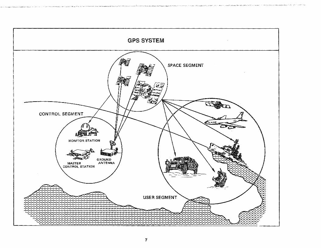
GPS is a space-based radiopositioning and time-transfer system. It comprises three major segments: Space, Control, and User.
The Space Segment, when fully operational, will have an Earth-orbiting constellation of 21 Navstar satellites (plus three onorbit operational spares) in six planes. They will operate in nominally circular 20,200 kilometer (10,900 nautical mile) altitude orbits inclined at an angle of 55 degrees with a 12-hour period. The spacing of satellites in their orbital planes will be arranged such that a minimum of four satellites will be in view everywhere on or near the surface of the Earth at any time. Each Navstar satellite is designed to broadcast a pair of L-band radio frequency (RF) signals, known as Link 1 (L 1) and Link 2 (L2). The L 1 signal carries a precision ranging code and a coarse/acquisition ranging code, while L2 carries only the precision ranging code. Superimposed on these codes are low-rate navigation message data, including satellite clock and ephemeris parameters, satellite signal health data, and Coordinated Universal Time (UTC) synchronization information.
The Control Segment includes a Master Control Station (MCS) along with a number of Monitor Stations (MSs) and Ground Antennas (GAs) located around the world. The MSs use a specialized GPS receiver to passively track all satellites in view. The information from the MSs is processed at the MCS to determine satellite clock and ephemeris values and to update the low-rate navigation message of each satellite. This updated information is transmitted to the satellites via the GAs.
The User Segment consists of a variety of UE sets, associated SE, and other items. The UE sets, passively operating on the L-band RF signals received from the orbiting satellite constellation, can provide PVT data to appropriately equipped users with accuracies of 16 meters spherical error probable (SEP) for position, 0.1 meters per second root mean square (rms) along any axis for velocity, and 100 nanoseconds (billionths of a second)
GPS SYSTEM
SPACE SEGMENT
-~ ~y GROUND MASTER ANTENNA
CONTROL STATION
7

one-sigma for time transfer. Furthermore, the GPS UE sets can be integrated with other self-contained navigation systems to provide accurate positioning under the adverse operating and environmental conditions.
1.3 BASIC SYSTEM CHARACTERISTICS
1.3.1 Precise Versus Standard Positioning Services
GPS has been designed to support the broadest possible spectrum of users. System-level PVT accuracy requirements have been established to satisfy the diverse needs of the GPS user community. The user's accuracy requirements fall into two basic categories, and these two categories required the development of two distinctly different GPS services. The two basic services, and the user PVT accuracy levels achievable with them, are known as the Precise Positioning Service (PPS) and the Standard Positioning Service (SPS). The PPS will satisfy those users who require a realtime military level of accuracy, whereas the SPS is designed to meet the needs of all other users. Functionally, the PPS and SPS are nearly identical. The essential difference between them is the accuracy achievable.
1.3.2 Positioning Versus Navigation Capabilities
Both the GPS PPS and SPS provide users with 3-D position and velocity determination capabilities along with a capability for precision time transfer, but neither one provides a "navigation" capability per se. Unlike true radionavigation systems such as TACAN, the GPS services provide "absolute" position and velocity information in the sense that the information is determined with respect to the World Geodetic System 1984 (WGS-84) absolute Earth coordinates-not with respect to a particular ground-based transmitter. The UE set position outputs (e.g., latitude, longitude, and altitude) therefore cannot be directly used for navigating relative to a particular fixed point in space the same way that the
8
range and bearing information from a T ACAN receiver can be used to steer directly to or from the location of the TACAN transmitter. Most UE sets do, however, have built-in functions that support area navigation (RNAV) and can generate steering (navigation) information relative to a user-specified waypoint. Many users employ their UE sets in this manner.
Even though it is technically correct to draw this distinction between "positioning" and "navigation" for GPS (the UE sets provide positioning information, while navigation is just one of the many possible applications for the positioning information), the two terms "positioning" and "navigation" are commonly misapplied and used interchangeably by most users. Fortunately, the misuse of these two terms does not pose a major problem in most contexts, and this overview will follow common practice in discussing various aspects of the GPS program whenever it is clear as to which definition is actually meant. When the context is unclear, however, the proper terminology will be used. As a simple mnemonic to keep the definitions of these two terms straight, it is worthwhile to remember "GPS" does not stand for "Global Navigation System."
1.3.3 Comparison with Other Positioning/ Navigation Systems
The accompanying table compares the horizontal (2-D) position and velocity determination capabilities of the GPS PPS and SPS versus the capabilities of other operational positioning/navigation systems. All positioning accuracy values are given in terms of a circular error probable (CEP). Velocity accuracy values are given in terms of an rms (or one-sigma) value along any axis. Even though GPS is a 3-D system, this comparison must be made on a 2-D basis because the other radionavigation systems do not provide vertical information.

HORIZONTAL POSITIONING/NAVIGATION SYSTEM COMPARISON
System
GPS/PPS
GPS/SPS
Position Accuracy (CEP1
}
Sm
40 m
Loran-c2 180 m
Omega2 2,200 m
Velocity Accuracy (rms)
0.1 m/sec
N/A
No velocity data
No velocity data
STD INS3 1,500 m max after 0.8 m/sec after 1st hour 2 hours
TACAN2 400 m No velocity data
Transit2 200 m No velocity data
Range of Operation
Worldwide
Same as GPS/PPS
Comments
Operational worldwide with 24-hour all-weather coverage.
Operational worldwide with 24-hour all-weather coverage.
U.S. coast, most of Operational with localized coverage. Limited by continental U.S., selected skywave interference. overseas areas
Worldwide
Worldwide
Line of sight (present air routes)
Worldwide
Operational worldwide with 24-hour coverage. Subject to propagation anomalies.
Operational worldwide with 24-hour all-weather coverage. Degraded performance in polar areas.
Position accuracy degraded mainly because of azimuth uncertainty, typically on the order of + 1.0 degree.
Interval between position fixes is about 90 minutes. For use in slow moving vehicles. Better position fix accuracy is available with dual-frequency measurements.
NOTES: 1CEP Is defined as the radius of a horizontal circle containing 50% of all possible position fixes 2Federal Radionavigation Plan, December 1990 3SNU-84-1 Soecification for USAF Standard Form. Fit. and Function (F3
) Medium Accuracy Inertial Naviaation Set/Unit. October 1984
9

1.3.4 Time-Transfer Capabilities
In addition to 3-D position and velocity determination capabilities, UE sets operating with the PPS or SPS can precisely transfer UTC-referenced time to users. The PPS UE sets have the capability to determine and transfer UTC with an accuracy of 100 nanoseconds one-sigma. The corresponding value for SPS UE sets is 0.17 microseconds (approximately 170 nanoseconds) onesigma.
1.4 END USER APPLICATIONS
Application of GPS to various military and civil operations will bring many benefits to the user. The GPS UE sets can serve as the single source for highly accurate positioning, velocity, and time data. Because GPS position is referenced to a common coordinate grid, WGS-84, both military and civil position data can be standardized on a worldwide basis. For operational ease, most UE sets can convert the WGS-84-referenced position fixes to other commonly used datums when operating with maps and other geodetic data products.
1.4.1 Military Applications
The substantial navigation performance improvements afforded by the GPS PPS will enhance many areas of military operations. Because GPS allows the use of a common grid, all aspects of air, ground, and sea interoperability can be greatly improved. These interoperability applications include close air support, rendezvous, multi-force command and control, pinpoint cargo drop operations, and search/rescue/evacuation operations. The precise timetransfer capabilities of GPS will allow global synchronization of electronic systems, thereby facilitating secure communications, electronic warfare, and advanced target-locating techniques.
10
In air operations, PPS accuracy can streamline enroute, terminal, and approach navigation, thereby reducing flight times and fuel consumption. (The same is also true with the lower SPS accuracy.) Since the GPS is a 3-D system, descent and nonprecision approach and landing can be more closely controlled. In combat-related applications, PPS performance will improve coordinate bombing and ballistic weapon delivery. Test results (discussed in Section 6) validated substantial improvements in such missions when supported by the very accurate PPS. These combat-related applications are where the superior accuracy of the PPS really makes its impact felt.
For ground forces, the PPS can provide similar combat-related advantages. The real-time precise positioning capabilities will enhance site surveying, field artillery placement, target acquisition and location, and target handoff operations. First-round artillery effectiveness will be improved based on precise knowledge of the location of friendly firepower, coupled with precision forwardobserver determinations of enemy locations and movements. In non-combat operations, PPS (and SPS) accuracy will support efficient off-road navigation for supply distribution, vehicle recovery, rendezvous, and reconnaissance, etc.
GPS can also provide major benefits to naval forces. Harbor navigation operations can be improved, coastal surveys can be conducted more quickly and effectively, and mine emplacement and countermeasure operations can be conducted with greater speed and safety, particularly with the PPS level of accuracy. The crew of a submarine can determine their position with pinpoint accuracy and update their inertial systems while keeping antenna exposure time to a minimum.
These are but a few of the military applications that will benefit from the GPS precise position, velocity, and time determination capabilities. GPS is truly a significant force multiplier for the military services.

GPS MILITARY APPLICATIONS
• ENROUTE NAVIGATION
• LOW-LEVEL NAVIGATION
• NONPRECISION APPROACH
• TARGET ACQUISITION
• CLOSE AIR SUPPORT
• MISSILE GUIDANCE
• COMMAND AND CONTROL
• All-WEATHER AIR DROP
• SENSOR EMPLACEMENT
• PRECISION SURVEY
• TIME SYNCHRONIZATION
• RENDEZVOUS
• COORDINATE BOMBING
• REMOTELY PILOTED VEHICLE OPERATIONS
• BAREBASE OPERATIONS
• SEARCH AND RESCUE
• PHOTORECONNAISSANCE
• RANGE INSTRUMENTATION
• MINE EMPLACEMENT AND COUNTERMEASURE
• SPACE NAVIGATION

1.4.2 Civil Applications
The GPS SPS will provide a broad spectrum of civil users with a sufficiently accurate Pvr determination capability at a reasonable cost. Based on the joint DoD and DoT agreement documented in the FRP, an SPS position accuracy specification has been established for the civil community. Civil users will be able to determine their position to within 100 meters 2 drms (twice the distance rms) once the full GPS constellation is operational.
Civil users of air, sea, and ground vehicles will benefit from the use of SPS for optimal course navigation, which will reduce fuel costs and transportation time. In civil aviation, the SPS will provide substantial benefits in enroute and terminal navigation, as well as in nonprecision approach and landing operations, based upon the 100 meter 2 drms position accuracy. In land navigation, GPS has found major applications in railroad operations and in the taking of the census.
The civil mineral exploration and geophysical survey communities will be able to accurately locate ore bodies, potential petroleum bearing areas, property lines, and active earthquake faults in a shorter period of time. Accurate positioning of oil exploration vessels is essential for pinpointing promising oilbearing geological formations from reflected seismic pulses, and several oil exploration companies are now using the SPS in conjunction with differential GPS (DGPS) techniques for this purpose. The current alternative, as employed on most oil exploration ships, is to use an assortment of navigational systems, including the less convenient Transit system and shore-based transmitters.
Search-and-rescue techniques can be enhanced through the use of the position identification capability of the GPS. Knowing the location of the nearest fire hydrant and being able to navigate directly to it will aid fire fighters. Likewise, civil authorities responding to natural disasters will be able to easily locate underground pipelines and storage tanks. Utility companies are also finding many similar uses for GPS.
12
GPS has even found several major applications In space. Beginning with NASA's LANDSAT-4 in the early 1980s and continuing through today's TOPEX and Gravity Probe B programs, spaceborne GPS receivers have demonstrated their capability for both real-time and post-processed orbit determination. Use of precise time from GPS has also played a significant role in the synchronization of ground-based spacecraft tracking networks; to give just one example, GPS-based precise time was essential to the successful Voyager 2 fly-by of Neptune in mid-1989.
The potential applications for GPS are boundless. As the system gains acceptance by the civil community, ever more sophisticated uses for this system will be established. That is why the developers of GPS consider it the positioning and time-transfer system for both today and tomorrow.
1.4.3 Civil Applications with the PPS
The DoD has also established a policy on the civil use of the PPS. This policy stipulates the requirements that must be met in order to grant limited civil access to full GPS accuracies. The requirements specify access may be allowed if:
a. It is in the national interest of the United States, and
b. The required accuracy cannot be achieved by other means, and
c. The security concerns of the GPS PPS are adequately provided for.
Further, the DoD Positioning/Navigation (POS/NAV) Working Group is developing an implementation plan to address associated issues.
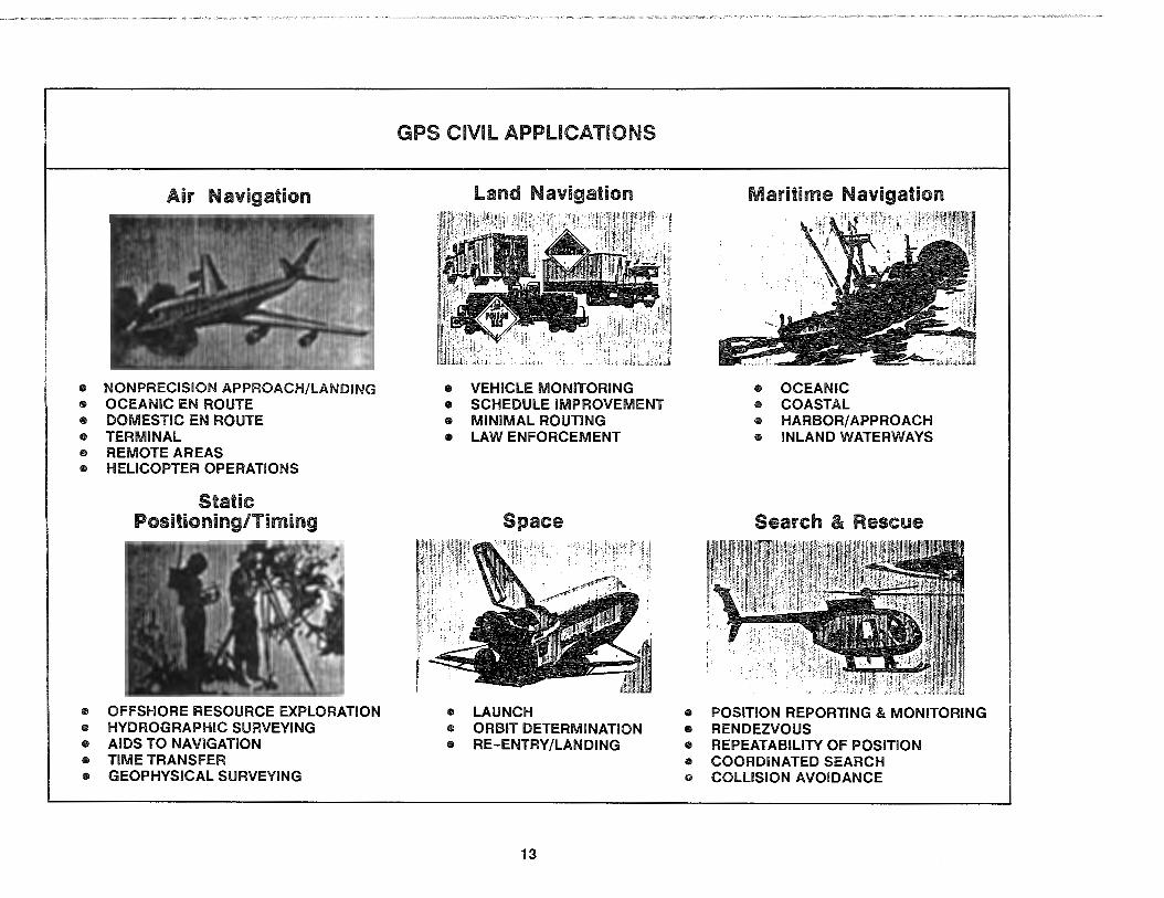
Air Navigation
• NONPRECISION APPROACH/LANDING • OCEANIC EN ROUTE • DOMESTIC EN ROUTE • TERMINAL • REMOTE AREAS • HELICOPTER OPERATIONS
Static Positioning/Timing
• OFFSHORE RESOURCE EXPLORATION • HYDROGRAPHIC SURVEYING • AIDS TO NAVIGATION • TIME TRANSFER • GEOPHYSICAL SURVEYING
GPS CIVIL APPLICATIONS
Land Navigation Maritime Navigation
• VEHICLE MONITORING • OCEANIC • SCHEDULE IMPROVEMENT • COASTAL • MINIMAL ROUTING • HARBOR/ APPROACH • LAW ENFORCEMENT • INLAND WATERWAYS
Space Search & Rescue
• LAUNCH • POSITION REPORTING & MONITORING • ORBIT DETERMINATION • RENDEZVOUS • RE-ENTRY/LANDING • REPEATABILITY OF POSITION
• COORDINATED SEARCH • COLLISION AVOIDANCE
13

2.0 PROGRAM BACKGROUND
2.1 ORIGIN
Since the early 1960s, both the Air Force and Navy have actively pursued the idea that positioning and navigation could be performed using RF signals transmitted from satellites. The impetus for such a space-based system was the potential for a global, all-weather, continuously available, highly accurate positioning and navigation system that could meet the needs of a broad spectrum of users and cut costs by stemming the proliferation of specialized equipment responsive only to particular mission requirements.
Toward this objective, the Navy sponsored two programs: Transit and Timation. Transit became operational in 1964 and currently provides periodic worldwide 2-D navigation information for the fleet ballistic missile submarine force and selected surface ships. It is a space-based radiopositioning system, similar to GPS in some ways but quite different in others. There are far fewer satellites in the Transit constellation and they operate in lowaltitude polar orbits. This system was made available to non-military users in 1967. Timation was a high-technology program managed by the Naval Research Laboratory (NRL) for advancing the development of high-stability clocks, time-transfer capability, and 2-D navigation. The last two Timation satellites were actually refurbished before launch to serve as the two prototype Navstar satellites.
The Air Force was simultaneously conducting concept studies to assess a 3-D (latitude, longitude, and altitude) navigation system with continuous service, called System 621 B. The system concept and techniques were verified in a series of tests and experiments at Holloman AFB and White Sands Missile Range in New Mexico. Most of these were conducted using an ingenious inverted range setup whereby satellite-type signals were generated by ground stations to provide ranging signals for aircraft positioning.
14
A memorandum issued by the U.S. Deputy Secretary of Defense in April 1973 designated the Air Force as the executive service to coalesce these and other concepts proposed for a Defense Navigation Satellite System (DNSS) into a comprehensive and cohesive DoD system. A system concept designated Navstar Global Positioning System emerged, combining the best features of the previous navigation satellite designs. The new system was to be developed by a joint program office (the GPS JPO), with participation by all military services.
Since its inception, the Navstar GPS JPO has guided the program to its current state of near completion. Over the years, both the GPS and the JPO have expanded in scope. Many organizations from each military service have become intimately involved with GPS and have contributed to the JPO's efforts. NATO cooperation on GPS began in 1978 and has grown to include the direct participation in the JPO by several NATO and other allied nations. Civilian users are now supported by a Do T representative at the JPO, and civil access to the GPS signal without charge was formally guaranteed by President Reagan in response to the Korean Airline disaster in 1983 (KAL-007).
The future outlook for the Navstar GPS is bright Section 507 of the International Maritime Satellite Communications Act of 1978 (PL 95-564) required the development of a formal plan to determine the most cost-effective method of reducing proliferation and overlap of federally funded radionavigation systems. That plan, the FRP, was developed through the joint efforts of the DoD and DoT. The FRP cites key criteria for selecting radionavigation systems and provides a DoD/DoT policy statement that sets forth a preliminary selection of the future radionavigation systems mix. It is the stated goal of the DoD to phase out military use of TACAN, VOR/DME, Omega, Loran-C, and Transit in aircraft and other platforms, focusing on GPS as the primary radionavigation for future military use. And, if the full civil potential of GPS is realized, the DoT will consider phasing out some of the existing radionavigation systems altogether.

GPS PROGRAM HISTORY
NAVSTAR GLOBAL
POSITIONING SYSTEM
15

2.2 GENERAL SCHEDULE
The development and acquisition of GPS has taken place in three general phases. The first phase was devoted to validating GPS concepts, the second to full-scale engineering development of its three segments, and the third to production/deployment. A fourth phase will begin once GPS reaches its full operational capability (FOC) milestone in 1993. Throughout its long and successful history, many different contractors and organizations participated in the GPS program and thereby made significant contributions to the science of navigation.
Phase I - Concept Validation
Phase I began with the establishment of the GPS JPO in 1973 and progressed through the developmental testing which validated GPS concepts and demonstrated its potential for operational utility. Phase I for the Space Segment took off with the launch of the two prototype Timation/Navstar satellites in 197 4 and 1977 and ended with the developmental Navstar satellites, built under contract by Rockwell International, being launched atop Atlas missiles from Vandenberg AFB (VAFB), CA. Soon after the onset of Phase I, the GPS JPO awarded a major contract to General Dynamics to: provide a prototype control system based at VAFB; build a test range at the US Army's Yuma Proving Ground (YPG), AZ.; and develop a family of UE set prototypes. The UE set development portion of the General Dynamics effort was subsequently subcontracted to Magnavox. Towards the end of Phase I, Texas Instruments and Rockwell-Collins were also awarded contracts to develop additional UE set prototypes for testing. This threecontractor approach enabled a variety of UE set configurations to be evaluated during field testing and to be analyzed using lifecycle cost models.
Phase II - Full-Scale Development
Phase II saw major engineering developments in each of the thrne segments as well as follow-on activities with Phase I assets.
16
In 1980, the Space Segment awarded a new contract to Rockwell International for the 28 second-generation Navstar satellites which would ultimately be launched using the Space Shuttle to create the operational constellation. Also in 1980, the Control Segment awarded its Phase II contract to IBM to operate and upgrade the prototype control system at VAFB to provide interim support for UE set testing plus the final developmental satellite launches while simultaneously developing a worldwide operational control system capable of supporting the second-generation satellites.
The User Segment took a different approach during Phase II and subdivided its activities into two stages. In Phase llA, four identical UE study /paper design contracts were awarded, one each to Texas Instruments, Magnavox, Rockwell-Collins, and Teledyne. At the end of Phase llA, the four proposed designs were evaluated in a competitive source selection that resulted in follow-on contracts awarded to Magnavox and Rockwell-Collins. Phase llB, commencing after the Defense Systems Acquisition Review Council (DSARC) II Milestone, featured continued design refinement, the building of preproduction prototypes, supportability planning, and extensive testing. The two separate contracts for Phase llB established a competitive fly-off environment which produced capable UE set designs and effective SE.
Developmental test and evaluation (DT&E) of the Phase llB UE set designs began in 1982 and was primarily conducted at YPG. It was followed by initial operational test and evaluation (IOT&E) conducted by the Army Operational Test and Evaluation Command (OPTEC, formerly OTEA), the Navy Operational Test and Evaluation Force (OPTEVFOR), and the Air Force Operational Test and Evaluation Center (AFOTEC), using a variety of platforms. The HVs used during Phase llB testing included F-16, A-6, and B-52 aircraft, an aircraft carrier, an attack submarine, UH-60 helicopters, and M-60 tanks, each with the Phase llB GPS UE integrated with on-board systems in a production look-alike manner. The test results are addressed in Section 6.

OVERALL PROGRAM
SPACE SEGMENT
CONTROL SEGMENT
USER SEGMENT
*
GPS PROGRAM SCHEDULE
73 I 7 4 I 75 I 76 I 77 I 78 I 79 I 80 I 81 I 82 I 83 I 84 I 85 I 86 I 87 I 88 I 89 I 90 I 91 I 92 I 93 I JliP"
... PHASE I
CONCEPT VALIDATION
PHASE II FULL-SCALE DEVELOPMENT
... ... ... PHASE Ill
JPO ESTABLISHED
NATO JSSMO PARTICIPATION ESTABLISHED
AFSPACECOM DESIGNATED OPERATOR
6. FOC
BEGINS
[==o=======[l=:;PH;A~S~E~l===~~=====lP~H~A~SiE~ll======~~==~~~~ ... ... ............................ ... FIRST ... SECOND
PROTOTYPE SATELLITE LAUNCHES
FIRST----------.... LAST
DEVELOPMENTAL SATELLITE LAUNCHES
A """" --Iii- ETC. FIRST-------11.,_
OPERATIONAL SATELLITE LAUNCHES
c===========~1 ___ P_H_A_S_E_1 _____ /_P_H_A_SE_11 ___ / ______ PH_A_S_E_1_11 _____ _ ... ... ... ... ... PROTOTYPE INTERIM OPERATIONAL AFSPACECOM SYSTEM SYSTEM SYSTEM OPERATIONS {VAFB) PHASE llA (VAFB) (VAFB/FAFB) (FAFB)
[_]l==~PH;A;S~E~l========::~+G;.~:::JP6H~A~S~E~ll~B::=:==:~~===P~H~A~S~E~ll;IA~===~~~P~H~A~S~E~ll~IB~___.-::::: ©* ©* ©*• ®* ©*• ~* 6.
DSARC II JAMB/DAB MILESTONE lllB
© = NUMBER OF MAJOR USER SEGMENT CONTRACTORS
17

Phase Ill - Production and Deployment
Phase Ill for the Space Segment has focused primarily on the rapid deployment of operational Navstar satellites using the Delta II Medium Launch Vehicle (MLV) built by McDonnell Douglas and launched from Cape Canaveral Air Force Station (AFS), FL Since initial plans had been to launch the satellites with the Space Shuttle, the scheduled start of Phase Ill for the Space Segment suffered a major delay as a result of the Challenger accident in 1986. It was not until 14 February 1989 that the first Delta II MLV was used to launch the first operational Navstar satellite into orbit. Subsequent launches of the second-generation satellites have been at the rate of about five per year.
The start of Phase Ill for the Control Segment came in October 1985 when the Operational Control System (OCS) began performing uploads to the prototype Navstar satellites from VAFB. Another major Control Segment event came about six months later when the installation at VAFB was decommissioned and all operations were transferred to a new master control station for the OCS located at Falcon AFB (FAFB), just outside Colorado Springs, CO. Following a gradual transition of operations from IBM to Air Force personnel, formal turn-over of the OCS from the JPO to Air Force Space Command (AFSPACECOM) was completed in April 1990.
Like Phase II, the User Segment also divided its Phase Ill activities into A and B stages. The Phase lllA effort began in 1985 with a competitive source selection between the two Phase llB contractors. Based on the results obtained with the UE set prototypes as well as many other factors, Rockwell-Collins was selected for and was awarded the LRIP contract on 1 April 1985 with five production options worth up to $452 million.
There were two reasons for awarding an LRIP contract rather than one for full-rate production. First, the observed reliabilities of the various UE sets during IOT&E were not up to their full specification values and it was necessary to improve the quality of the winner's equipment before entering full-rate production. By taking
18
the LRIP approach, the required manufacturing and design improvements could be made in a production-line environment and a period of reliability demonstration testing (ROT) conducted to ensure the full specification values would indeed be met. The second reason for the LRIP contract was the delay in the start of Phase Ill for the Space Segment which meant there would be little need for full-rate production quantities of UE sets until the early 1990s. Thus, the LRIP contract quantities would be adequate to support both the needs of the ROT effort and those users with early-on requirements.
With the Phase lllA manufacturing and design improvements well under way, the initial production option on the RockwellCollins LRIP contract was exercised by the JPO after receiving a favorable decision from the Joint Requirements Management Board/Defense Acquisition Board (JRMB/DAB) in mid-1986. This initial production go-ahead led to the first Phase lllA UE set being delivered to the JPO 15 months later. Other production options on the LRIP contract were exercised, thus ensuring a steady flow of UE sets into the military inventory through 1992. The Phase lllA ROT /DT&E testing concentrated on the deficiencies identified during Phase II to ensure the final designs were ready for full-scale production. Follow-on operational test and evaluation by the individual services on HV-installed equipment will be completed to support the full-rate production decision (Milestone lllB).
In October 1987, the JPO awarded two second-source UE contracts to Canadian Marconi and SCI Technology for manufacturing build-to-print copies of certain Rockwell-Collins military specification (MILSPEC) GPS receiver /data processors. These contracts were set up as leader-follower arrangements with Rockwell-Collins being the leader for both second sources. The two second-source contracts were awarded in order to foster competition on the most expensive LRUs and thereby reduce overall system life cycle costs. The program management responsibility for these second-source contracts was transferred after their award to the Naval Avionics Center (NAC), in Indianapolis, IN.
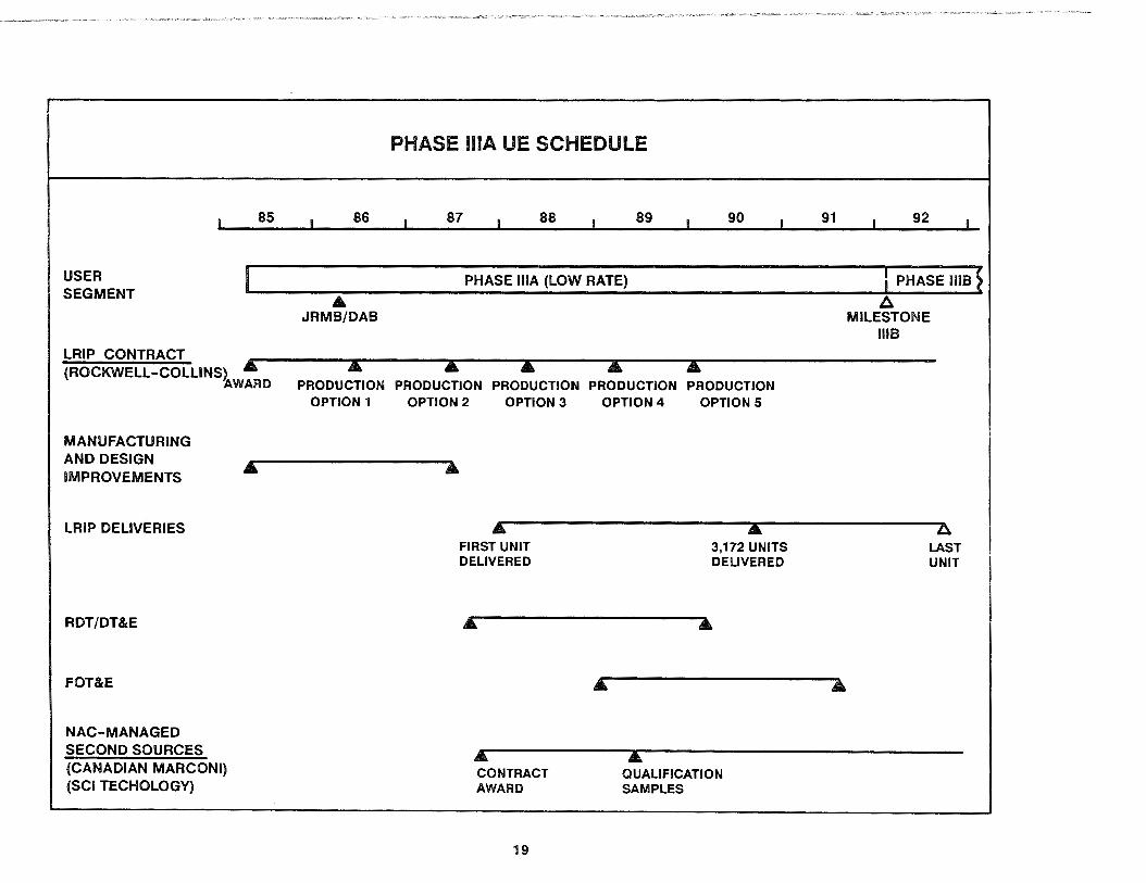
USER SEGMENT
85
LRIP CONTRACT (ROCKWELL-COLLINS) &
7'WARD
MANUFACTURING AND DESIGN IMPROVEMENTS
LRIP DELIVERIES
RDT/DT&E
FOT&E
NAC-MANAGED SECOND SOURCES (CANADIAN MARCONI) (SCI TECHOLOGY)
86
A JAMB/DAB
PHASE lllA UE SCHEDULE
87 88 89 90
PHASE lllA (LOW RATE)
PRODUCTION PRODUCTION PRODUCTION PRODUCTION PRODUCTION OPTION 1 OPTION 2 OPTION 3 OPTION 4 OPTION 5
" FIRST UNIT DELIVERED
" CONTRACT AWARD
19
A 3,172 UNITS DELIVERED
A QUALIFICATION SAMPLES
91 92
I PHASE ms~ ~
MILESTONE lllB
A LAST UNIT

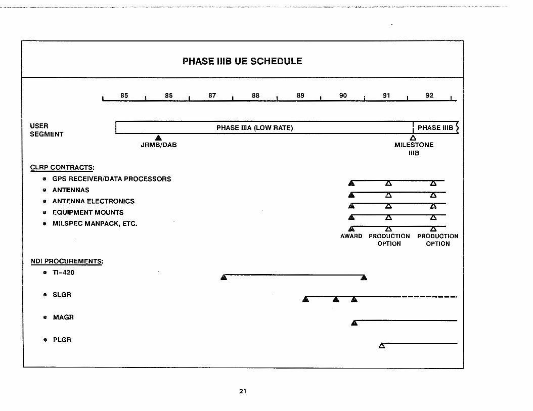
The benefit of establishing second-source contracts was realized during the summer of 1990 when the User Segment conducted a CLRP procurement as the Phase 1118 follow-on to the LRIP contract. This CLRP procurement was structured differently from the LRIP contract in that there were five completely separate contracts awarded on a cost-competitive basis, one for each major class of MILSPEC UE set components instead of just one contract covering all the equipment. Like the LRIP contract, however, the CLRP contracts included multiple production options covering component deliveries for 1992 through 1996.
One of the second-source contractors-SCI Technology-won the CLRP contract for the GPS receiver /data processor LR Us. Although not previously established as second-source suppliers, E-Systems won the pair of CLRP contracts for build-to-print antenna system LRUs, while Hollingsead International won the contract for equipment mounts. The original MILSPEC design developer, Rockwell-Collins, was awarded the contract for the selfcontained, man-portable UE set (called a "manpack", but able to be mounted in ground vehicles and watercraft), as well as other selected LRUs, SE, and miscellaneous items.
The start of Phase 1118 for the full-rate production of MILSPEC UE set components is dependent on the final outcome of the FOT&E and RDT /DT&E to be presented and decided upon at Milestone 1118. Until then, the CLRP contracts will continue at their present low rate of production.
In addition to reducing costs through second-source contracting for competitiveness during Phase lllA/8, the JPO has explored several other innovative alternatives to gaining the maximum utility at minimum cost. First and foremost, the JPO has encouraged other qualified manufacturers to participate in the GPS UE program by way of NDI procurements. This NDI procurement approach is based on buying commercial-type UE sets instead of MILSPEC ones whenever their performance is adequate to satisfy one or more military mission needs. Any militarization or other special development needed is performed by the potential NDI vendor before the vendor submits samples for evaluation. This
20
might mean no more than painting the equipment green, for example. The NDI method of procurement has been very successful so far, largely because of the growing market for commercial GPS equipment. Some of the more significant NOi procurements have included the units described below. (Additional information on each one will be found in Section 5.)
• In September 1987, an NOi procurement was conducted for a lighter manpack UE set (1 O lbs as compared to 17 lbs for the MILSPEC unit) with certain PPS capabilities. As a result, an order was placed with Texas Instruments for 250 of their commercial Tl-420 UE sets with an upgraded version of software that had the required PPS functions. Delivery of these units ran from November 1988 until the end of 1990, and they are currently deployed in operational use by field troops.
• In July 1989, another NDI procurement was held for a much smaller and lighter (about 5 lbs) manpack called SLGR (for Small Lightweight GPS Receiver). This UE set was intended only for troop familiarization and demonstration of GPS capabilities, so an SPS unit was determined to be adequate. Trimble Navigation won the original competition with an order for 1,000 SLGRs. The SLGR program was quite successful in introducing GPS to a great many operational Army units as well as many other military organizations. With the advent of Operation Desert Shield in the latter half of 1990, the military services which used the SLGRs in demonstration exercises recognized it offered them the capabilities they needed in order to navigate and operate effectively in a desert area with few landmarks and even fewer roads. As a result, most of the SLGRs were deployed to Southwest Asia and saw operational use along with the manpacks built by RockwellCollins and Texas Instruments. The SLGR units have proved so useful to the troops that the demand for them resulted in two high-priority purchases of several thousand additional SLGRs for use in Desert Shield and Desert Storm.
USER SEGMENT
CLRP CONTRACTS:
85 86
• JRM8/DAB
• GPS RECEIVER/DATA PROCESSORS
e ANTENNAS
• ANTENNA ELECTRONICS
• EQUIPMENT MOUNTS
• MILSPEC MANPACK, ETC.
NDI PROCUREMENTS:
• Tl-420
• SLGR
• MAGR
• PLGR
PHASE me UE SCHEDULE
87 88 89 90
PHASE lllA (LOW RATE)
&.
&. &. &.
&. AWARD
91 92
l PHASE 1118 ~ /::,,.
MILESTONE 1118
ZS: ZS:
ZS: ZS: ZS: ZS: ZS: ZS:
ZS: ZS: PRODUCTION PRODUCTION
OPTION OPTION
Ar--~ ... --... ..--------·-------·
A
21
• In November 1990, an NOi procurement contract for a much smaller (3/8 ATR short), PPS-capable, aircraft-type GPS receiver/data processor nicknamed MAGR (Miniaturized Airborne GPS Receiver) was awarded to RockwellCollins. MAGR units will be used in those aircraft installations where the MILSPEC GPS receiver /data processors are unable to fit because of their greater size and weight.
• Due to the success of the SLGR program, a follow-on NOi procurement of a PLGR (Precision Lightweight GPS Receiver) is also planned by the JPO. The request for PLGR bid samples is currently scheduled to be issued during the late summer of 1992 with contract award the following winter.
Phase IV - Full-Scale Operations
Phase IV will start once the DoD issues its formal FOC declaration for the Navstar GPS. This is expected to occur soon after 21 of the operational Navstar satellites are in orbit, around the middle of 1993.
For the Space Segment, Phase IV will start with the launch of three additional spare satellites to join the on-orbit constellation. These satellites will be fully functional and available for use since they are spare only in the sense they are extras placed into orbit to ensure the availability of the nominal 21 satellite constellation. As time goes on and the original satellites begin to fail, the spare satellites will be maneuvered to fill in for the failed ones and replacements will be launched as needed to maintain 21 satellites plus up to three operating spares. The Control Segment will continue to provide the day-to-day operations for both the PPS and SPS.
22
During Phase IV, the User Segment is expected to grow both in technical capabilities (smaller equipment and more applications) and in total user population (military and civil). After FOC Is reached, DoD plans are to phase out requirements for all other common-use radionavigation systems except for Instrument landing system/microwave landing system (ILS/MLS) and shipboard TACAN. Current indications are that the military forces of allied countries will do likewise. Continued use of NOi procurements for military UE sets can be anticipated whenever a lower total lifecycle cost can be achieved without sacrificing operational suitability. A depot-level Integrated Support Facility (ISF) will be in operation for organic support of MILSPEC UE set software. Overall system management responsibility for GPS will transition from the JPO to WR-ALC during Phase IV.
Because of the accuracy, global coverage, and flexibility provided by GPS, civil use is expected to grow rapidly after FOC. Widespread national and international use of the SPS for geodetic surveying, for air, land, and sea navigation, and for other applications is foreseen. Initially, civil aircraft will probably use GPS as a supplementary system for en route domestic and foreign flights; such use will depend on the resolution of safety-of-flight issues. Ultimate approval for general aviation use of GPS as a sole-meansof-navigation system, including use for nonprecision approach to landing, should come as a result of long-term negotiations among users, the DoD, the DoT, and the International Civil Aviation Organization (ICAO).
Two to three years after the start of Phase IV, a third generation of Navstar satellites-already being developed by General Electric-will be launched to replenish the on-orbit constellation. These satellites incorporate several new features that, once a sufficient number of them are on orbit, will enhance the operational suitability of the PPS and SPS under a variety of conditions. These features will carry GPS well into the 21st century.


2.3 GPS PROGRAM ORGANIZATION
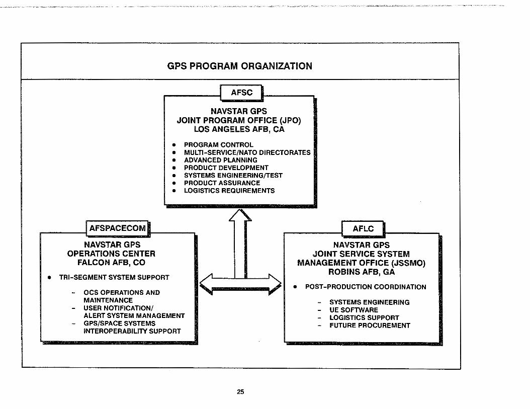
The GPS program is a multiservice effort, directed by the DoD. The Air Force has been designated as the executive service for program development. AFSC is the implementing command for the User, Control and Space Segments. AFSPACECOM is designated as the operating command and the Air Force Logistics Command (AFLC) is designated as the supporting command.
2.3.1 AFSC
The overall GPS program is managed by AFSC through the JPO located at Headquarters Space Systems Division (SSD), LAAFB, CA. The GPS Program Director (PD) is delegated authority to plan, organize, coordinate, . control, and direct the overall program. Participation in the JPO by other services and agencies, including Army, Navy, Marine Corps, DoT, OMA, NATO, and allied nation personnel is coordinated through appropriate Deputy Program Managers (DPMs).
Superimposed on the JPO's DPM organization is a supporting matrix organization comprising engineering, logistics, and contract management teams covering each major development/acquisition contract associated with the three program segments. This structure provides the framework that enables the GPS PD to effectively manage the overall program with respect to cost, schedule, and performance.
2.3.2 AFSPACECOM
Various organizations within AFSPACECOM have been established to operate and maintain the OCS, control the on-orbit con-
24
stellation, and Interface with the user community to discuss GPSrelated matters. AFSPACECOM coordinates with the JPO to establish a constellation build-up plan that will support the user community. An operational capability (OPSCAP) reporting and management system is being implemented to assess the OPSCAP status of the system and to enable AFSPACECOM to disseminate this status to users.
2.3.3 AFLC
AFLC, through the Director of Logistics at the JPO, ensures that logistics support planning Is accomplished for each segment during the system development period, culminating In program management responsibility transfer (PMRT) to the appropriate AFLC Air Logistics Center (ALC). This support planning includes integration, personnel, training, supply support, test equipment and maintenance. Long-term User Segment support responsibilities have been assigned to WR-ALC and are being coordinated through the JSSMO at WR-ALC, RAFB, GA. Like the JPO, the JSSMO is a joint service organization with direct participation of service personnel. Program management responsibility for the overall system will ultimately transfer to WR-ALC as well.
Program management responsibilities for the OCS logistics, documentation, and maintenance were transferred from the JPO to WR-ALC in October 1987. In late 1989, these OCS support responsibilities were transferred from the WR-ALC to Sacramento ALC (SM-ALC) as part of the Air Force initiative to normalize space operations (PACER FRONTIER). The Space Segment will remain the responsibility of the JPO and will not have a PMRT to an ALC in the near future.
AFSPACECOM
GPS PROGRAM ORGANIZATION
AFSC
NAVSTAR GPS JOINT PROGRAM OFFICE (JPO)
LOS ANGELES AFB, CA
111 PROGRAM CONTROL 111 MULTI-SERVICE/NATO DIRECTORATES • ADVANCED PLANNING 111 PRODUCT DEVELOPMENT • SYSTEMS ENGINEERING/TEST 111 PRODUCT ASSURANCE • LOGISTICS REQUIREMENTS
------.... AFLC
NAVSTAR GPS NAVSTAR GPS OPERATIONS CENTER
FALCON AFB, CO
111 TRI-SEGMENT SYSTEM SUPPORT
JOINT SERVICE SYSTEM MANAGEMENT OFFICE (JSSMO)
ROBINS AFB, GA
- OCS OPERATIONS AND MAINTENANCE
- USER NOTIFICATION/ ALERT SYSTEM MANAGEMENT
- GPS/SPACE SYSTEMS INTEROPERABILITY SUPPORT
25
• POST-PRODUCTION COORDINATION
- SYSTEMS ENGINEERING - UE SOFTWARE - LOGISTICS SUPPORT - FUTURE PROCUREMENT

2.4 NATO/AUSTRALIAN INVOLVEMENT
The United States encouraged NATO participation in the development of the GPS. In response, 10 NATO nations signed a Memorandum of Understanding (MOU) in June 1978 for participation in the Phase II and Ill development of the GPS. In addition to the United States, participating nations were Belgium, Canada, Denmark, France, Germany, Italy, the Netherlands, Norway, and the United Kingdom. Australia began participating in the program in 1984. In April 1987, Spain joined the other participating nations, and, with the signing of the renegotiated MOU, which covers the period until December 1993, Portugal and Turkey became aligned users.
The objective of the MOU is to establish a flow of information among the participating nations in all GPS program activities. This will facilitate national decisions to support the applications of GPS. To this end, personnel of these nations are fully integrated within the GPS JPO to contribute to the U.S. development program and to advise on and coordinate NATO applications, development, and testing. This group is referred to as the NATO team and is headed by a NATO DPM who plans, controls, and coordinates the NATO GPS project. The NATO DPM is directly responsible to the NATO Steering Committee composed of one representative from each participating nation.
The NATO GPS project is financed by the participating nations. The Steering Committee allocates funds· for the studies and tests considered to be of special interest to the NATO community. Major NATO and Australian GPS activities undertaken to date include:
26
• Production of a draft NATO Standardization Agreement (STANAG 4294), defining GPS In terms of signal-in-space, navigation message format, and system accuracy. The NATO nations believe the existence and approval of such a STANAG is essential before a commitment can be made to the adoption, nationally, of GPS.
• Production of a publicly releasable document entitled NavstarUser Equipment Introduction, which explains many features of the system.
• Studies and trials related to ionospheric effects on GPS signals in arctic latitudes (Norway).
• Jamming tests on various aircraft (United Kingdom).
• Electromagnetic interference and electromagnetic compatibility (EMl/EMC) testing of GPS receivers (Germany).
• GPS integration concept studies and practical integrations of GPS into a number of NATO and Australian host vehicles.
European-built GPS UE sets were successfully flown and tested at the YPG. GPS UE set testing is also taking place in NATO nations on a variety of military vehicles.
The NATO nations are starting to include requirements for GPS in new platforms and platforms slated for mid-life upgrades.
Several companies within the NATO nations are producing GPS UE sets and are offering them for sale in Europe and the U.S.

-·---....... ... i··_,.r,,..,,.
"' ""''"""'"'"''"'" .>~~j,,
27

3.0 SYSTEM TECHNICAL DESCRIPTION
3.1 BASIC OPERATING CONCEPTS
GPS position determination is based on a concept called ''time of arrival ranging". The simplest form of this concept consists of a broadcast beacon which sends out a signal starting at some precise instant in time and a receiver which picks up the signal at some later point in time. By observing the time difference between when the signal was sent out by the broadcast beacon and when the signal arrived at the receiver, we can determine the time of arrival (rOA) value. And by multiplying the observed TOA value by the signal propagation speed, we can compute the receiver's distance (range) away from the beacon.
As an example of this TOA ranging concept in action, assume the broadcast beacon is a foghorn that starts blowing exactly on the minute mark, and let the receiver be a mariner with a chronometer. If the sound of the foghorn arrives at the mariner's ear exactly 1 O seconds after the minute mark, then the resulting 10-second TOA observation will lead the mariner to compute a range from the foghorn of 3,400 meters, (i.e., the 10-second TOA value times the 340 meter-per-second speed of sound). If this mariner also took a second TOA observation from another foghorn, then the mariner's position relative to those two foghorns could be fixed by plotting the intersections of the two TOA-based range circles centered on each of the foghorn locations. And as long as the latitude/longitude coordinates of the two foghorns are known to the mariner, the latitude/longitude coordinates of the mariner's position can be pinpointed (diagram A on the accompanying figure).
This relatively simple TOA ranging concept works quite well when two conditions are satisfied: 1) that the mariner begins with a good estimate of his/her general position, and 2) that the mariner's chronometer has no error. If the mariner does not begin with a good position estimate, then there is a chance the mariner might initially assume a position at the other intersection point shown on diagram A. This won't happen if the mariner starts the
28
TOA-based ranging at a known dockside location and keeps good track of the changing position fD<es while navigating; but if for some reason the mariner gets distracted and loses track, then during the next position flX the mariner might inadvertently assume the wrong intersection point. Diagram B shows that one way around the potential for intersection ambiguity is for the mariner to listen to a third foghorn. With three TOA-based range measurements, there will be four intersection points. Only one intersection point will be common to all three TOA-based range circles; the other three intersections will be false ones.
The effect of a chronometer time bias error is shown in diagram C. If the mariner's chronometer Is running one second fast, then the sound of the foghorn that arrives 1 o seconds after the minute mark will appear to arrive 11 seconds after the minute mark. This will lead the mariner to compute an erroneous range of 3,740 meters away from that foghorn. And since the same chronometer is used to observe the TOA from other foghorns, their resulting TOA-based range observations will also be biased by an extra 340 meters (shown as the range error, E). With only two range observations from two foghorns, the mariner would end up with an erroneous position fix.
Diagram D shows the way around this problem is also to listen to the third foghorn. Having already eliminated the false intersection ambiguity, there will still be three dual-foghorn intersections near the mariner's true position. The separation between the intersection of the range circles from foghorns 1 and 2, the intersection from foghorns 1 and 3, and the intersection from foghorns 2 and 3 is strictly a function of the chronometer's time bias. This fact provides the mariner with a way to zero out the chronometer's time bias by adjusting it forward or backward until the three dual-foghorn intersections converge at the true position.
The net result of all this Is that our mariner will be able to determine three unknown quantities Oatitude, longitude, and chronometer time bias) by making three TOA-based range measurements and knowing certain facts about the three transmitting beacons.

BASIC OPERATING CONCEPTS
A. TOA-BASED POSITION DETERMINATION
LATITUDE
LLONGITUDE
LOCATION OF
FOGHORN~ N0.1
TOA-BASED RANGE N0.1
C. EFFECT OF A CHRONOMETER BIAS
FOGHORN N0.1
FOGHORN N0.2
B. ELIMINATING FALSE INTERSECTION AMBIGUITY
@,@,AND@ ARE FALSE INTERSECTIONS
D. TOA-BASED POSITION AND TIME DETERMINATION
...._ __ ._....
29
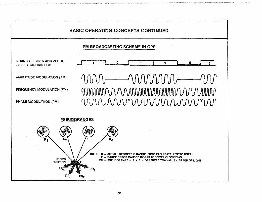
In GPS TOA ranging, orbiting Navstar satellites are the broadcast beacons at the center of TOA-based range spheres and the signals they send at the speed of light are pseudorandom noise (PAN) sequence-modulated L-band radio waves. These PAN sequences-the coarse/acquisition (C/A) and the precision (P)-codes are no more than predefined strings of one and zero data bits generated from an on-board satellite clock that serve as the time of transmission encoding for the broadcast signals. The satellites broadcast their PAN sequences using a form of digital phase modulation (PM) radio. PM radio differs from the familiar amplitude modulation (AM) and frequency modulation (FM) radio in that changes in the carrier wave phase are used instead of changes in the carrier wave amplitude or frequency to communicate whether a one or a zero is being transmitted. GPS PM radio also differs from common AM/FM radio in that each satellite transmits its own unique PAN sequence of ones and zeros, enabling users to tell the individual signals apart even though all satellites broadcast using the same L-band carrier frequency. In AM /FM radio, each transmitter must broadcast using its own unique frequency to avoid interfering with other transmitters. In the Soviet Union's GLONASS system (which is quite similar to GPS), each satellite must also transmit using its own unique carrier frequency to avoid interference because they all use the same PAN sequence of ones and zeros. More details on the nature of the Navstar satellite signals will be provided later.
In GPS, the mariner's ear, chronometer, plotting table, and calculator are replaced by an integrated unit (the UE set) which does all the work automatically for the user. The PM radio part of the UE set (known as the GPS receiver) is able to "tune in" on a desired satellite's particular signal by generating a precise replica of its P- or C/A-code and mixing it with the incoming L-band radio waves. By slewing the replica PAN sequence forward and backward in time, an exact match-called "correlation"-with the desired incoming signal will eventually be achieved. The amount of slewing back and forth required to achieve this correlation becomes the GPS receiver's observed TOA value. As long as the receiver continually adjusts the amount of slewing and maintains the correlation between the incoming PAN sequence and the
30
replica PAN sequence, the satellite's signal will be tracked and the observed TOA values may be sampled as often as required.
If the clock in the GPS receiver used to generate the replica PAN sequences were exactly synchronized to the on-board satellite clocks, the TOA values observed by the receiver would be equal to the actual geometric ranges between the satellites and the user divided by the speed of light (analogous to the mariner's situation once the chronometer time bias has been zeroized and brought into synchronization with the foghorns). In GPS however, it is simply not practical to physically adjust the receiver's clock to zeroize its time bias. Since the mariner works with signals traveling at the speed of sound, the chronometer only needs to be adjusted to within a few thousandths of a second to get very good ranging accuracy. But because GPS works with signals traveling at the speed of light, the physical adjustment would have to be within a few billionths of a second.
To solve this problem in GPS, the clock in the receiver is left free-running and the data processor portion of the UE set mathematically solves for the amount of adjusting that would be needed to zeroize the clock's time bias. (This amount is known as the GPS receiver clock bias term, or CB.) As a result, the GPS receiver's observed TOA values will be the actual range from each satellite divided by the speed of light plus some constant amount of time equal to the CB. And when the data processor takes the observed TOA values and multiplies them by the speed of light, the resulting quantities will be the actual ranges from each satellite to the user plus some constant range error equal to the CB times the speed of light. We call these quantities "pseudorange measurements" because they are almost like measuring the range from the satellites except for the range error caused by the GPS receiver's CB. This is a very important concept and deserves a formal definition: A pseudorange (PR) measurement is equal to the GPS receiver's observed TOA value times the speed of light where the observed TOA value includes both the signal propagation delay due to the actual geometric range plus the GPS receiver's clock bias.
STRING OF ONES AND ZEROS TO BE TRANSMITTED:
AMPLITUDE MODULATION (AM)
FREQUENCY MODULATION (FM)
PHASE MODULATION (PM)
BASIC OPERATING CONCEPTS CONTINUED
PM BROADCASTING SCHEME IN GPS
j 1 0 1 1 0 I
PSEUDORANGES
NOTE: R = ACTUAL GEOMETRIC RANGE (FROM EACH SATELLITE TO USER) E = RANGE ERROR CAUSED BY GPS RECEIVER CLOCK BIAS
PR = PSEUDORANGE = R + E = OBSERVED TOA VALUE x SPEED OF LIGHT
31
1
3.2 SIMPLIFIED USER POSITION/TIME COMPUTATION PROCESS
Once the GPS receiver starts tracking the PRN sequences from four satellites and generating TOA values, the UE set's data processor takes over. It first samples the TOA values from the GPS receiver for each of the four satellites and multiplies them by the speed of light to produce four PR measurements. The data processor then adjusts these PR measurements to compensate for deterministic errors such as the difference between each satellite's clock and GPS system time, the atmospheric distortion of the signals (light travels in a straight line at a constant speed only in a vacuum), the effects of relativity as predicted by Einstein, etc. The UE set gets the information it needs to compute these adjustments to the PR measurements from a 50 Hz (Hertz) digital data stream the satellites broadcast along with their P- and Cf A-codes. This 50 Hz digital data stream, the "navigation message," will be described in further detail later.
After the data processor makes all the necessary adjustments to the PR measurements, it then performs the position/time solution process to determine the user's location. This position/ time solution process may be thought of as mathematically solving a set of four ranging equations, using the four PR measurements to determine four unknown quantities. The four unknown quantities are the user's X-position coordinate, Y-position coordinate, Z-position coordinate, plus the CB. This is analogous to our mariner plotting out a two-dimensional position fix and zeroizing the chronometer time error using the intersection of three TOAbased range circles; but because GPS is a three-dimensional positioning system (X, Y, Z), a fourth TOA-based range sphere is needed. The fact the GPS satellites are continually moving as compared to the mariner's fixed-location foghorns is of no consequence, since the broadcast 50 Hz navigation message contains the information needed by the data processor to compute the satellite's exact position at each point in time.
32
The data processor computes its X, Y, Z position fix in terms of the WGS-84 coordinate system which forms the basis for the GPS worldwide common grid referred to earlier. Depending on the particular type of UE set involved, the X, Y, Z coordinates will normally be converted to latitude, longitude, and altitude (variable units and formats) in the WGS-84 or other user-selectable local map datum prior to output or display. The GPS position solution is intrinsically referenced to the electrical phase center of the UE set antenna, not to the location of the GPS receiver or data processor (the antenna can be several hundred meters away from the GPS receiver/data processor in some UE set installations). In certain installations where a lever arm and HV attitude are available, the results may be translated to a different point on the HV-such as the center of gravity or an on-board inertial navigation system (INS)-prior to output.
The data processor computes its CB results in terms of the time offset of the clock in the GPS receiver versus GPS system time. The data processor can relate the CB results to UTC by way of satellite-broadcast terms in the 50 Hz navigation messages that relate GPS system time to UTC. Exactly how the UE set provides UTC as a final output will be explained later.
Under certain conditions, a UE set can compute a position/ time fix using PR measurements from less than four satellites. To do so requires the data processor to receive external aiding information. Typical aiding information includes an input of altitude from a barometric altimeter, knowledge that the UE set is installed on a ship and the antenna is a fixed distance above mean sea level (MSL), or an input of precise time from a HV-installed atomic clock. These aiding sources can each replace one satellite-based PR measurement in the solution process. By using both altitude and precise time aiding, it is possible to determine both latitude and longitude using PR measurements from only two satellites.

SIMPLIFIED USER POSITION/TIME COMPUTATION PROCESS
A. DATA PROCESSOR OBTAINS PSEUDORANGE MEASUREMENTS (PR1' PR2, PR3, PR4) FROM FOUR SATELLITES
TIME-CODE TIME EACH SIGNAL SIGNALS ~ RECEIVED BY USER TRANSMITTED BY EACH
n ~ PR1 = /:;,. T1 x c • • - PR2 = .6. T2 x c
6, T3 n PR3 = /:;,. T3 x c AT4 n A
B. DATA PROCESSOR APPLIES DETERMINISTIC CORRECTIONS
PR I= PSEUOORANGE (I = 1, 2, 3, 4)
PR4 =~T4xc (c = SPEED OF LIGHT)
• PSEUOORANGE INCLUDES ACTUAL DISTANCE BETWEEN SATELLITE AND USER PLUS SATELLITE CLOCK BIAS, ATMOSPHERIC DISTORTIONS, RELATIVITY EFFECTS, RECEIVER NOISE, AND RECEIVER CLOCK BIAS
• SATELLITE CLOCK BIAS, ATMOSPHERIC DISTORTIONS, RELATIVITY EFFECTS ARE COMPENSATED FOR BY INCORPORATION OF DETERMINISTIC ADJUSTMENTS TO PSEUOORANGES PRIOR TO INCLUSION INTO POSITION/TIME SOLUTION PROCESS
C. DATA PROCESSSOR PERFORMS THE POSITION/TIME SOLUTION
FOUR RANGING EQUATIONS:
= ( PR1 - @ x c)2
= (PR2 - @ xc)2
= ( PR3 - @ x c)2
= ( PR4 - @ x c)2
XI • YI • Z I = SATELLITE POSITION (l = 1, 2, 3, 4)
• SATELLITE POSITION BROADCAST IN 50 Hz NAVIGATION MESSAGE
DATA PROCESSOR SOLVES FOR: e Ux, Uy, Uz = USER POSITION • CB = GPS RECEIVER CLOCK BIAS
33

3.3 POSITION AND TIME ACCURACY FACTORS
The accuracy of the UE set's position and time solution is determined by two very important factors. The first is the error in the measurement of PRs from each satellite being tracked. The second is the satellite-to-UE geometry. Knowing these two factors for a particular UE set at a particular point in time and space is important because it allows us to understand the limitations of GPS and enables us to actually forecast the UE set's position and time accuracy.
3.3.1 User Equivalent Range Error (UERE)
The error in the UE set's measurement of the PRs from each satellite is called the "user equivalent range error" or UERE. The UERE is itself the product of several factors: the stability of the particular satellite's clock, the predictability of the satellite's orbit, errors in the satellite-broadcast 50 Hz navigation messages, the precision of the GPS receiver PRN sequence tracking (correlation) design, errors in the data processor's deterministic adjustment of the PR measurements for atmospheric distortions, and so on. Because the UERE depends in part on the quality of the broadcast signal-in-space, it will vary from satellite to satellite and from time to time. Because the UERE also depends on the design of the particular GPS receiver /data processor, it may vary for each type of UE set.
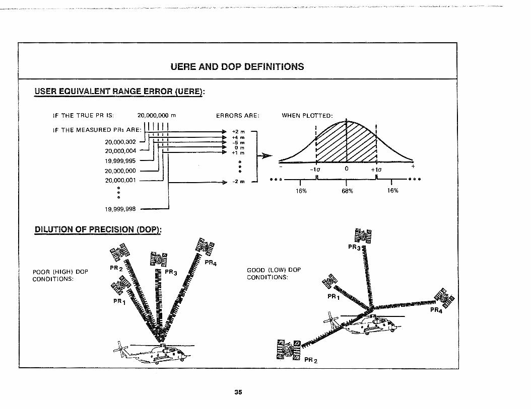
Accuracy values quoted for UEREs are typically given in terms of a one-sigma statistical value, which is basically the same as the standard deviation of the PR measurement errors. This means 68% of the PR measurements for the specified UE set under the specified signal-in-space conditions will have a UERE in the range between plus/minus the quoted one-sigma value. For the mathematically inclined, it is worthwhile to note the UERE is a onedimensional quantity-it is the accuracy of the PR measurements along the line-of-sight direction from the particular satellite to the
34
particular UE set-and will follow a zero-mean, Gaussian probability distribution. As such, the one-sigma value for UERE will be equal to the rms value of a very large population of PR measurement errors.
3.3.2 Dilution of Precision (DOP)
The second accuracy limiting factor is called the "dilution of precision" or DOP. The DOP depends only on the geometry of the four satellites used by the UE set to determine its position and time. It is independent of the quality of the broadcast satellite signals and the type of UE set as long as the same four satellites are selected. The DOP is basically an amplification factor that multiplies the UEREs and increases the UE set position/time solution errors.
A "good" DOP means the satellites exhibit good geometry as seen by the UE. Good DOPs are low numbers while poor DOPs are high numbers. Low DOP numbers result when the satellites are widely spaced in the sky above the UE set The best possible geometry for a ground-based UE set is to have one satellite directly overhead with three satellites equally spaced around the horizon. High DOPs result when the satellites are close together or when they line up to form a row or circle in the sky. In rare circumstances, the DOP factors can become so large they prevent the UE set from processing a position/time solution fix.
There are special types of DOPs for each of the position and time solution dimensions. For the vertical dimension, a ''vertical DOP" (VDOP) is used to describe the effect of satellite geometry on the UE set altitude errors. For the horizontal (circular) dimension, a "horizontal DOP" (HOOP) value describes the effect of satellite.geometry on the UE latitude-longitude errors. Similarly, the time dimension effect of geometry is given by the "time DOP" (TDOP) value; the combined vertical-horizontal (spherical) dimension by the "position DOP" (POOP) value; and the combined vertical-horizontal-time dimension by the "geometric DOP" (GDOP) value. There are other, less often used DOPs as well.
UERE AND DOP DEFINITIONS
USER EQUIVALENT RANGE ERROR (UERE):
IF THE TRUE PR IS: 20,000,000 m ERRORS ARE: WHEN PLOTTED:
IF THE MEASURED PRs AREji-1....,1....,1....,1....,l _____ ~ill +2 m
20.000.002~ :J' : : : E ~i : 19,999,995 •
• 20,000,000 • -la 0 +la
20,000,004 =.J I ' !ilP> +1 m
20,000,001 ---' i------1111>' -2 m •••~-.--~ll1i...--__,,__ _ __.1,~•--r--~•••
19,999,998
DILUTION OF PRECISION (DOP):
POOR (HIGH) DOP CONDITIONS:
35
16%
GOOD (LOW) DOP CONDITIONS:
M ...
68% 16%
3.3.3 (Navigation) Position and Time Errors
Knowing the UERE and OOP values seen by a particular UE set at a particular point in time and space allows us to forecast that UE set's "navigation" (actually, position) and time errors. This forecasting ability is vital because of its twin roles in:
a. Real-time performance estimation within the UE set, and
b. Planning and analyzing missions using GPS.
Exactly how and why the UE set estimates its own real-time performance will be explained in paragraph 5.1 while how the user forecasts navigation and time errors for mission planning/ analysis will be explained in paragraph 5.3. Even though these topics are covered elsewhere, many important GPS concepts are best explained by reviewing the manual method for forecasting navigation and time errors.
Navigation and time error forecasting is simple when all satellite signals-in-space give the same UERE. In this case, the forecast navigation and time errors can be computed by simply multiplying the appropriate OOP value by the common satellite UERE value in meters. As an example, if the geometry of the four satellites to be tracked by a particular UE set has an HOOP value of 1.5 and the satellites' signals-in-space all result in the same UERE of 7.0 meters one-sigma, then the forecast UE horizontal navigation error would be a "distance root mean square" (drms) circle with a radius given by 1.5 times 7.0 meters, or 10.5 meters.
This "drms" nomenclature is only one of the many standard ways of expressing navigation errors. A "10.5 meter drms circle" means if one were to run many trials with GPS and measure the miss distance of each horizontal fix from the true location point, then the rms value of all the miss distances would be 10.5 meters. Another way to look at the 10.5 meter drms number is that it is the radius of the circle that contains approximately 63% of all possible horizontal position fixes that will be obtained with GPS under these HOOP and UERE conditions. (Because hori-
36
zontal position is two-dimensional, its rms value is close to the one-sigma 68% probability but not exactly equal to it.)
Just as for horizontal navigation errors using the HOOP value, drms errors can be forecast using the other OOP quantities as well. Special acronyms are used for these statistical forecasts as a way to distinguish them from other ways of expressing errors. UHNE is the acronym for the "User Horizontal Navigation Error" drms value computed with HOOP. Similarly, UVNE stands for the "User Vertical Navigation Error" drms value computed with VOOP, UTE stands for the "User Time Error" drms value computed with TOOP, and UNE stands for the three-dimensional (horizontal plus vertical) "User Navigation Error" drms value computed with POOP. There is no corresponding drms acronym for the four-dimensional GOOP.
Some of the other ways of expressing errors use their own acronyms while some do not. For example, Spherical Error Probable (SEP), Circular Error Probable (CEP), Linear Error Probable (LEP), and Time Error Probable (TEP) are the 50% probability distances which are analogous to UNE, UHNE, UVNE; and UTE respectively. The twice-the-distance-rms (2 drms) way of expressing errors uses the drms definitions except that the distances are multiplied by a factor of 2. The use of so many ways to express errors is often quite confusing and can lead to erroneous forecasting conclusions. Caution should always be exercised when comparing navigation errors to ensure they are expressed the same way, and quoted accuracies should never be trusted unless it is clear what definition is being used.
Because the UE set navigation and time error statistics are basically no more than the satellite signal UEREs multiplied by the appropriate OOP values, forecasting them requires not much more than forecasting the UEREs and the OOPs. The UE set portion of the UERE is usually calibrated by the manufacturer and the satellite portion of the UERE is forecast by the Control Segment and provided to the users in the satellite-broadcast 50 Hz navigation messages. The OOPs can be forecast as a function of the user's location and time, as well as the number of satellites visible and their locations.

POSITION/TIME ERROR COMPUTATIONS
GOOP = GEOMETRIC DILUTION OF PRECISION
UERE = USER EQUIVALENT RANGE ERROR = COMBINATION OF:
= PR MEASUREMENT ACCURACY (ONE SIGMA)
= PRODUCT OF MANY FACTORS:
Ill POSITION DILUTION OF PRECISION (POOP) 9 TIME DILUTION OF PRECISION (TOOP)
POOP = COMBINATION OF:
9 SATELLITE SIGNAL-IN-SPACE STABILITY 8 HORIZONTAL DILUTION OF PRECISION (HOOP) 9 VERTICAL DILUTION OF PRECISION (VDOP) 8 GPS RECEIVER SIGNAL TRACKING PRECISION
e DETERMINISTIC CORRECTION ACCURACY HOOP =COMBINATION OF: 9 ETC.
* only when all satellites have the same UERE
** drms accuracy values *** c = speed of light
MULTIPLY TOGETHER* TO RESULT IN
8 EAST DILUTION OF PRECISION (EDOP) 9 NORTH DILUTION OF PRECISION (NDOP
THREE-DIMENSIONAL USER NAVIGATION ERROR (UNE)**
UNE = UERE x POOP
TWO-DIMENSIONAL USER HORIZONTAL NAVIGATION ERROR (UHNE)**
UHNE = UERE x HOOP
ONE-DIMENSIONAL USER VERTICAL NAVIGATION ERROR (UVNE)**
UVNE = UERE x VDOP
ONE-DIMENSIONAL USER TIME ERROR (UTE)**
UTE = UERE x TOOP 7 c***
37

3.4 MAJOR SYSTEM COMPONENT DESCRIPTIONS
GPS comprises three major segments: Space, Control, and User. There are also three major system-level interfaces between these segments: Space-to-User, Control-Space, and Control-toUser. This section begins with a description of the Space-to-User interface© because of its central role in the GPS operating concept. The major segments will then be addressed in turn: starting with the Space Segment® because its role is to provide the Space-to-User interface, then the Control Segment® because its function is to support the satellites of the Space Segment and optimize the Space-to-User interface, and ending with the User Segment© because it is the beneficiary of the Space-to-User interface. This section concludes with a description of the Contralto-User interface® because of its role in assisting the User Segment make the best use of the Space-to-User interface. The bi-directional Control-Space interface® is mentioned only briefly since its effect on users is indirect.
3.4.1 Space-to-User Interface Description
The interface between the Space Segment and the User Segment is often referred to as the GPS "signal-in-space" or SIS. The GPS SIS interface comprises the PAN sequence ranging codes, the L-band carrier waves, and the 50 Hz navigation message data streams broadcast by each satellite in the constellation. Even though the User Segment is the beneficiary of the SIS interface, the Control Segment also uses the SIS interface for its precision tracking of the Navstar satellites since the Control-Space interface does not have sufficient accuracy.
Many different manufacturers have been able to design UE sets to track the broadcast PM radio signals and provide the user with phenomenally accurate PVT information. A full description of the SIS interface is provided in the Interface Control Document (ICD) titled "Navstar GPS Space Segment/Navigation User Interfaces," ICD-GPS-200. Although many of the technical details are of interest only to UE set manufacturers, the following paragraphs summarize key SIS interface topics important to all GPS users.
38
3.4.1.1 PRN Sequence Ranging Codes
The two primary PAN sequences used for TOA ranging in the GPS SIS are now called the "coarse/acquisition" (C/A) and the "precision" (P) codes although they were originally called the "clear/acquisition" and "protected" codes. The C/A-codes are 1023-bit-long PAN sequences that repeat every millisecond. The short I ength of the C /A-code sequence allows for quick acquisition and aids the receiver in handing over to the much longer P-code sequences. The C/A-codes can also be used as the sole TOA ranging codes for GPS receivers with no P-code capability even though their relatively slow rate Oust over one million code bits per second) makes their performance somewhat coarser than the P-code signal. A unique C/A code is assigned to each satellite, allowing the satellite's broadcast to be distinguished from the other satellites' broadcasts at the same L-band carrier frequency via a technique known as code division multiple access (CDMA).
The P-code PAN sequences are approximately 6.2 trillion bits long and repeat once each week. Because the P-code sequences are clocked at a rate 1 O times faster than the C /A-code sequences (10.23 MHz versus 1.023 MHz), they are approximately ten times more precise and provide 10 dB more resistance to jamming. There are 32 unique P-code sequences allocated for satellite use and five "spare" P-code sequences reserved for other uses such as ground transmitters. Each satellite is assigned its own P-code, again allowing use of common carrier frequencies via the CDMA technique without causing interference.
Since each satellite broadcasts using its own unique C/A- and P-code sequences and since the C/A- and P-code sequences are defined as a matching numbered pair, the PAN sequence numbers provide a .convenient method of uniquely identifying each active satellite in the on-orbit constellation. In fact, from the user's perspective, the PRN sequence numbers are the only means available to identify individual satellites. GPS therefore, always uses the PAN sequence numbers as satellite identification numbers whenever communicating with its users (e.g., "PRN #1" means that particular satellite which is broadcasting with the "number one" C/A- and P-codes).
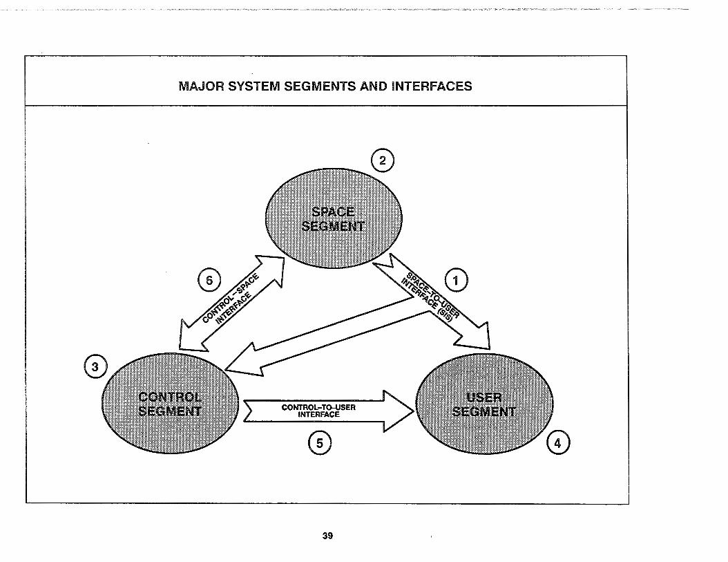
MAJOR SYSTEM SEGMENTS AND INTERFACES
CONTROL-TO-USER INTERFACE
0
39

3.4.1.2 L-Band RF Carrier Modulation
The C/A- and P-codes are used by the satellites to phase modulate two RF carrier waves: an l 1 carrier at a frequency of 1575.42 MHz and an l2 carrier at 1227.60 MHz. The particular form of PM radio used is known as "phase shift keying" (PSK). The l 1 carrier is PSK modulated by both the P-code and, 90 degrees out of phase, by the C /A-code. The l 1 signal is the sum of these two components. The l2 carrier is normally PSK modulated only by the P-code although, under certain circumstances, the satellite can be switched to modulate l2 with the C/A-code.
This PSK type of PM radio results in a spread spectrum waveform wherein the RF signal power is diffused over a wide bandwidth. PSK modulation of the RF carriers by the P-code spreads the power out over a 20.46 MHz bandwidth centered at the carrier frequencies (1575.42 MHz and 1227.60 MHz) while the C/A-code simultaneously spreads the l1 carrier out over a 2.046 MHz bandwidth 90 degrees out of phase (also centered on the l 1 frequency). This spread spectrum waveform was selected for use in the GPS SIS because of its strong resistance to interference and jamming. The jamming resistance is a function of the amount of spreading; the more spreading achieved, the more resistant the signal will be to jamming. This is why the antijamming performance of the P-code signal is 1 O dB better than the C /A-code signal.
One property of the spread spectrum waveform is the total amount of RF power at any specific frequency in each bandwidth is very, very low (actually below the level of background noise at the Earth's surface). The Cf A-component of the l1 signal peaks at -160 dBW (decibels with respect to one watt), the P-code component of l 1 peaks at -163 dBW, and the l2 P-code peaks at -166 dBW. The user's GPS receiver makes use of an advanced correlation technique to track the incoming PRN code sequence of these very low RF power levels in the GPS SIS, effectively despreading the waveform and recovering the carrier wave at its nominal frequency. This property of the correlation technique offers a major benefit to the user's GPS receiver that will be discussed in Section 5.
40
3.4.1.3 50 Hz Navigation Message Data Stream
The 50 Hz navigation message data stream contains the satellite-specific and system information required by the UE set to allow it to generate position fixes. Even though the navigation message does not contain any "navigation data" per se, it is still called the "navigation message• for historical reasons. The navigation message data stream is transmitted from the satellite by simply adding it in a modulo-2 fashion to the P- and C/A-code bit streams. Because the transmission rate of this data stream is very low relative to the PRN codes, its addition has no effect on the operation of the P- and C/A-codes.
The navigation messages broadcast by the satellites consist of 25 frames of data, each 1,500 bits in length. At a transmission rate of 50 Hz, an entire navigation message takes 12.5 minutes to be transmitted. Each frame is divided into five subframes containing 300 bits. Subframes 1 , 2, and 3 repeat the same satellite-specific data in all frames. Subframe 1 contains the satellite clock bias parameters which precisely give its specific offset from the GPS master clock along with terms that describe the accuracy and "health" of the satellite's SIS. Subframes 2 and 3 provide highprecision ephemeris parameters which allow accurate computation of the satellite's location at each point in time. The satellitespecific clock and ephemeris parameters in subframes 1, 2, and 3 are required by the UE set before it starts using the satellite for position fixing, and their repetition every 30 seconds supports rapid UE set startup operations. Each satellite broadcasts its own unique subframe 1 /2/3 data.
Subframes 4 and 5 contain low-precision clock and ephemeris (called "almanac") data for every satellite in the constellation. Subframes 4 and 5 also contain information such as health and configuration status for all satellites, user text messages, and parameters describing the offset between GPS system time and UTC. Because this constellation-related data is distributed throughout the 25 frames of the navigation message at the rate of one almanac or deterministic correction per subframe, a UE set requires 12.5 minutes to collect an entire set of subframe 4 /5 data. Each satellite transmits the same set of subframe 4/5 data as all other satellites in the constellation.
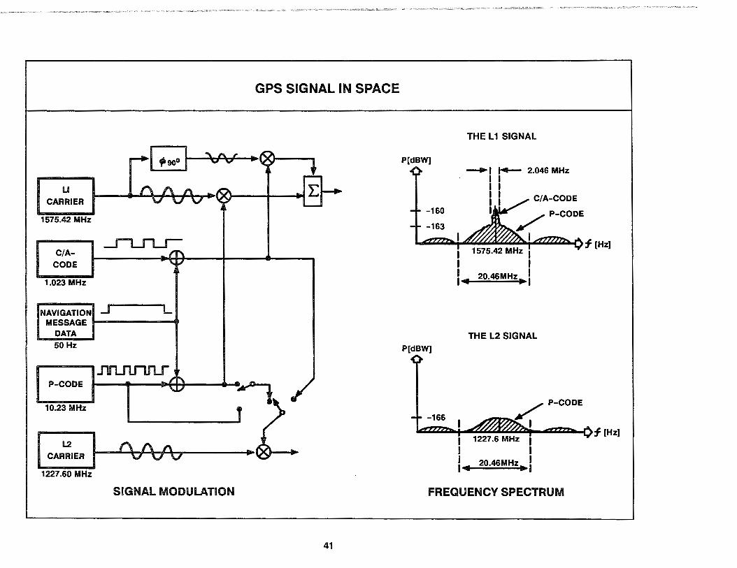
GPS SIGNAL IN SPACE
LI CARRIER
1575.42 MHz
C/ACODE
1.023 MHz
NAVIGATION _j L MESSAGE ..._ _____ ..
DATA 50 Hz
P-CODE
10.23 MHz
I CAR~••• ... 1 _ _._Q~v~"'"/\-lv~""o~v------••x•-_. 1227.60 MHz
SIGNAL MODULATION
41
P[dBW]
-160
-163
P[dBW]
THE L 1 SIGNAL
-.1 ~ 2.046 MHz I I I I I I Iv CIA-CODE
/ P-CODE
I f (Hz] I 1575.42 MHz I I I I I I 4 20.46MHz ... I
THE L2 SIGNAL
FREQUENCY SPECTRUM
3.4.1.4 Special SIS Interface Features
There are two special SIS interface features which all GPS users should be aware of. These features are called Selective Availability (SA) and Anti-Spoofing (A-S).
The SA feature allows the intentional introduction of errors into the SIS interface, along with encrypted correction parameters which allow certain users to remove the effects of those errors. SA is the mechanism used to control the SIS portion of the UERE and, via the DOP equations, limit the positioning/navigation accuracy achievable by users who are unable to decrypt the SA correction parameters. SA is always on, but the level of errors added to the SIS may be set to zero.
The A-S feature allows the P-code portion of the SIS interface to be encrypted. The encrypted P-codes are known as "Y-codes". A-S is the mechanism used in the military environment to foil an adversary's attempt to use a deception jammer (i.e., a broadcast beacon that mimics the SIS) to spoof the UE set into tracking the deception jammer signals instead of the actual satellite-transmitted signals. Since the deception jammer cannot autonomously generate the Y-codes needed to mimic the SIS, spoofing is prevented when A-S is applied. Unlike the SA feature, A-S may be either on or off.
In terms of user reaction to SA and A-S, there are two categories both of users and of UE sets. Users are divided into those who are authorized to receive the special cryptographic variables (CVs, also called cryptokeys) needed to decrypt the SA correction parameters and to encrypt the P-codes, and those users who are not authorized to receive the CVs. UE sets are divided into those having cryptographic logic built into them to do the decryption/ encryption processing (PPS-capable UE} and those UE that do not (SPS UE). The definition of "PPS-capable UE sets" does not
42
require the UE set to have both the decryption logic for obtaining the SA correction parameters plus the encryption logic for operating with the Y-codes; one or the other is sufficient to make it a PPS-capable UE set. SPS UE sets, by definition, have neither decryption nor encryption logic. Thus there can be PPS-capable UE sets that only track the C/A-code and SPS UE sets that track the P-code, but there can never be an SPS UE set that tracks the Y-code.
The division of users and their UE into categories based on SA/ A-S corresponds to a like division in terms of the SIS interface itself. The two aspects of the SIS interface are:
• Standard Positioning Service (SPS). SPS is the limited accuracy service available to all users of the SIS interface. No keys or cryptographic logic are required to access the SPS. The effect of SA and A-S on the SIS are felt. The SPS is intended primarily for civil GPS users.
• Precise Positioning Service (PPS). PPS is the full accuracy service available only to authorized users of the SIS interface. Both keys and cryptographic logic are required. The effects of SA and A-S on the SIS are counteracted. The PPS is intended for U.S. and allied government agencies and their military forces and, if in the national interest, to selected civil GPS users.
Note there is truly only one SIS interface from each satellite; the difference between the SPS and PPS aspects is strictly from the user perspective. The SPS aspect is that which is available to unauthorized users with SPS UE sets as well as unauthorized users who might have PPS-capable UE set or authorized users who have .SPS UE sets. The PPS aspect ls that which is available only to authorized users who have PPS-capable UE (i.e., both keys and cryptographic logic are required for the PPS).
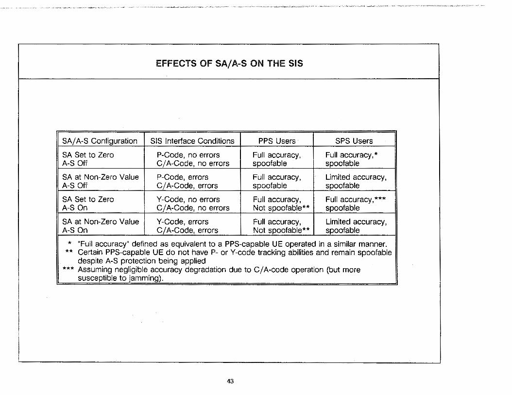
EFFECTS OF SA/ A-S ON THE SIS
SA/ A-S Configuration SIS Interface Conditions PPS Users SPS Users
SA Set to Zero P-Code, no errors Full accuracy, Full accuracy,* A-S Off C /A-Code, no errors spoof able spoofable
SA at Non-Zero Value P-Code, errors Full accuracy, Limited accuracy, A-S Off C /A-Code, errors spoof able spoofable
SA Set to Zero Y-Code, no errors Full accuracy, Full accuracy,*** A-S On C /A-Code, no errors Not spoofable** spoofable
SA at Non-Zero Value Y-Code, errors Full accuracy, Limited accuracy, A-S On C /A-Code, errors Not spoofable** spoofable
* "Full accuracy" defined as equivalent to a PPS-capable UE operated in a similar manner. ** Certain PPS-capable UE do not have P- or Y-code tracking abilities and remain spoofable
despite A-S protection being applied *** Assuming negligible accuracy degradation due to C/ A-code operation (but more
susceptible to jamming).
43
3.4.2 Space Segment Description
From the user's perspective, the GPS Space Segment comprises the constellation of Navstar satellites-also known as space vehicles (SVs)-in orbit around the Earth. Each SV is about the size and weight of a small automobile. The role of the Space Segment is to provide a sufficient number of SIS interfaces to users at all times to allow for accurate four-SV position solutions. Survivability requirements dictate the on-orbit SVs must be able to continue providing their SIS interfaces autonomously for an extended period of time without Control Segment support. The Navstar SVs-regardless of their evolutionary block type-perform this function the same basic way: by maintaining very stable orbital trajectories, by using ultra-high precision atomic clocks to generate their PM radio signals, and by basing their broadcast 50 Hz navigation message data stream on stored clock and ephemeris predictions periodically refreshed by the Control Segment.
Block 0 (NTS) SVs
The very first Navstar SVs, designated as Navigation Technology Satellite (NTS) numbers 1 and 2, were basically refurbished Timation satellites built by the NRL. These SVs were used for concept validation purposes and carried the very first atomic clocks ever launched into space. Although functioning for only a relatively short period after their launches in 1974 and 1977, they proved out the concept of TOA-based ranging using PM spread spectrum signals derived from on-orbit atomic clocks.
Block I SVs
The Block I SVs, built by Rockwell International as developmental prototypes, were launched between 1978 and 1985 from VAFB, CA These SVs supported most of the system testing. Out of a total of 11 Block I SVs launched on the Atlas-Centaur, one
44
was lost as a result of a launch failure, three have reached end-oflife due to wear-out of their atomic clocks, and two suffered failures of their three-axis attitude control system. The remaining five Block I SVs continue to function in service as of the date of this revision. The oldest Block I SV (PRN #6) has operated reliably for more than double its five-year design life. With reliability improvements made to the atomic clocks on the later Block I SVs based on failure analyses from the early launches, it is conceivable some of these Block I SVs will continue operating and providing positioning service into the 21st century.
Block II SVs
On-orbit testing of the Block I SVs identified several significant capability enhancements in subsystem design for future SVs. Many of these enhancements were folded into the design for the second-generation Block II SVs along with several changes necessary to support the full operational GPS system requirements. While most of the design differences affected only the internal Control-Space interface, some did result in changes to the SIS interface. Significant Block II SV enhancements that affected the SIS interface included:
• Radiation hardened electronics to prevent random memory upset events to improve SIS reliability and survivability.
• Capacity to store 180 days worth of 50 Hz navigation message data, compared to only 3.5 days worth of storage in the Block I SVs, to guarantee SIS availability.
• Full SA and A-S capabilities to provide for SIS security.
• Automatic detection of certain error conditions and switching to non-standard PRN code transmission or default navigation message data (alternating ones and zeros) to protect users from tracking a faulty SV and maximize SIS integrity.

SPACE VEHICLE EVOLUTION
BLOCK 0 (NTS) SATELLITE BLOCK I SATELLITE
BLOCK II SATELLITE BLOCK llR SATELLITE
45

The first of 28 Block II SVs was launched on 14 February 1989 from Cape Canaveral AFS, FL using a Delta II MLV and was set "healthy" in its broadcast 50 Hz navigation message for global use on 15 April 1989. This was SV PRN number 14. Since then, there have been nine more Block II SV launches-each of which successfully reached its final orbital destination. The remaining 18 Block II SVs will be launched over the next few years, with one launch occurring approximately every two to three months. After launch, the Block II SVs undergo a thorough month-long checkout period. They are then set "healthy" for use and take their place in the unfolding constellation in the sky. Like the Block I SVs, the Block lls are also built by Rockwell International.
Block llR SVs
During the middle of 1989, Phase Ill for the Space Segment began with the procurement of 20 additional "replenishment" satellites (the Block llR SVs) from General Electric. Already well under way, the Block llR SV development effort represents a further step in the evolution of the GPS Space Segment. Under normal circumstances, the Block llR SVs will present an identical SIS interface to the User Segment. Under a survivability scenario, however, operations for the Block llR SVs will differ radically from the Block I and Block II SVs. If something should happen to the Control Segment which prevents it from contacting the Block I and Block II SVs in orbit, these SVs will simply continue to transmit the stored 50 Hz navigation message data previously uploaded by the Control Segment for 3.5 and 180 days respectively. Because the Control Segment's ability to forecast the SV clock and orbital trajectories is limited, the accuracy of the SIS will gracefully degrade over time. By contrast, the Block llR SVs will have the capabilities to autonomously navigate (AUTONAV) themselves and generate their own 50 Hz navigation message data. These AUTONAV capabilities will enable the Block llR SVs to maintain full SIS accuracy for at least 180 days without Control Segment support. AUTONAV will also significantly improve both the reliabil-
46
ity and integrity of the broadcast SIS. The first launch of a Block llR SV is currently scheduled for 1995.
3.4.2.1 The Deployed Constellation
When fully deployed in 1993, the on-orbit GPS constellation will consist of 21 operating Block II SVs plus three active spares. The 21 SVs will be arranged with three or four SVs in each of six nearly circular orbital planes as shown on the facing page; the spare SVs will be placed in the three-SV planes to bring them to a total of four SVs per plane as well. All six orbital planes have an inclination angle relative to the equator of 55°, and the SVs will have an average orbit altitude of 20,200 km (10,900 nmi) relative to the surface of the Earth. This is the semi-synchronous altitude where a complete orbit takes about one-half sidereal day to complete; the SVs will thus follow a ground track which repeats every sidereal day (approximately 23 hours, 56 minutes). Users on the ground will observe the same SVs passing overhead each day through the same regions of the sky, but the SVs will be seen to rise and set about four minutes earlier on each succeeding day. By way of comparison, most communication satellites are in orbits almost twice as high as the Navstar SVs where their ground track remains fixed over one point on the equator.
The spacing of the SVs in their orbital planes was designed to maximize the probability that at least four SVs with good DOP will always be visible to users at every location on Earth. See Section 4 for additional details on SV coverage.
3.4.2.2 The Future of Remaining Block I SVs
The Block I SVs were launched into 63° inclined orbits and do not fit within the defined Block II SV constellation. Plans are to rely on the Block I SVs to augment the coverage provided by the growing complement of Block II SVs until there are 21 of the Block II SVs are on orbit. After that point in time, the future of the Block I SVs is uncertain.
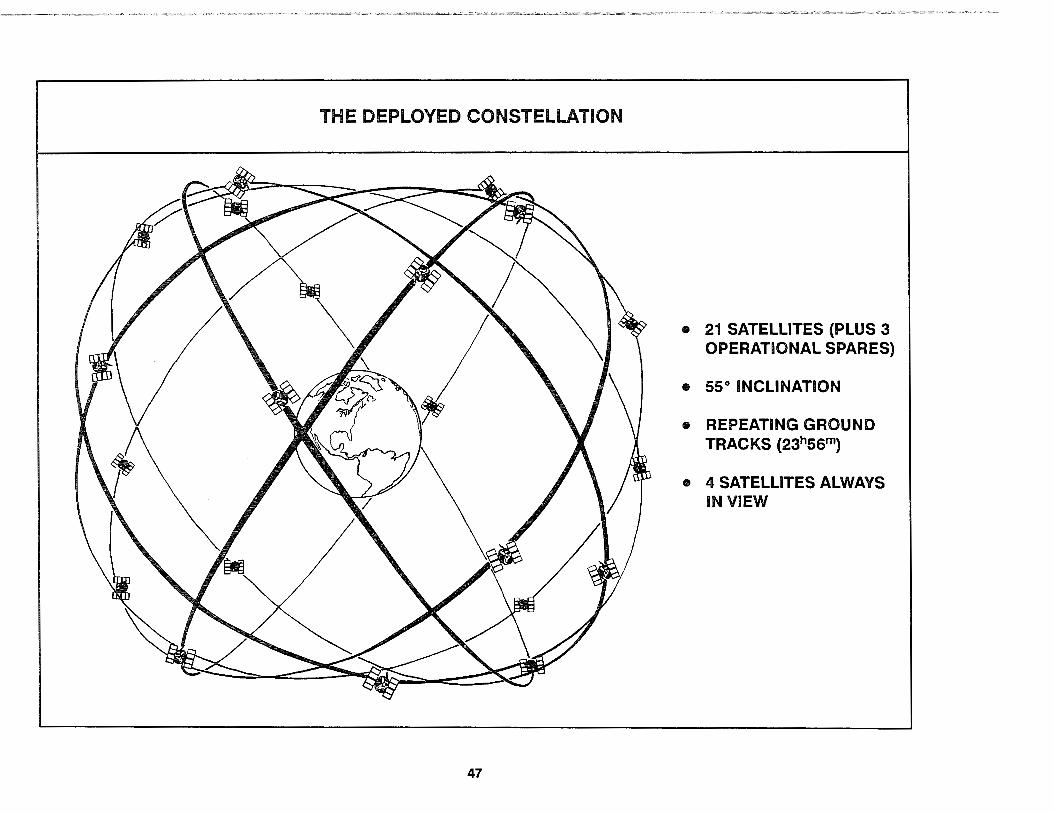
THE DEPLOYED CONSTELLATION
47
• 21 SATELLITES (PLUS 3 OPERATIONAL SPARES}
• 55° INCLINATION
• REPEATING GROUND TRACKS (23h55m}
• 4 SATELLITES ALWAYS IN VIEW
3.4.3 Control Segment Description
The names "Control Segment" and "Operational Control System" (OCS) are now synonymous in GPS program terminology, but this was not always the case. Before the OCS was built, the on-orbit SV support role of the Control Segment was fulfilled by the Initial Control System (ICS) and, before that, by the Phase I Control System. In parallel with the Space Segment, the Control Segment has also evolved from the research and development stage into a fully capable operational GPS Segment.
The OCS comprises the MCS, five MSs, three GAs, one Prelaunch Compatibility Station (PCS), and a network of communication lines connecting the MCS to each of the other component sites. The MCS is located in the Consolidated Space Operations Center (CSOC) at FAFB, CO. It is the central processing facility for the OCS network and is manned 24 hours per day, 7 days per week by trained operating crew personnel from AFSPACECOM's Second Satellite Control Squadron (2SCS).
One MS is located with the MCS at FAFB, and the others are on Hawaii, Ascension, Diego Garcia, and Kwajalein. They are unmanned installations operated under remote control of the MCS. The MSs basically function as very precise PM radio receivers, tracking the SIS from each SV in view at their surveyed locations
48
(up to 11 SVs simultaneously on both l1 and l2). They perform almost no processing of the data, instead sending their raw PR measurements and 50 Hz navigation message observations back to the MCS for processing In real time.
The OCS's GAs are co-located with the MSs on Ascension, Diego Garcia, and Kwajalein. There Is no GA at the MCS or in Hawaii. The PCS, located at Cape Canaveral AFS, is used primarily for checkout of the SVs prior to launch but can also be used as a backup GA in the event of a failure in one of the overseas GAs. Like the MSs, the GAs are also unmanned installations operated under remote control of the MCS. Their function is to provide the ground side of the Control-Space interface and enable the MCS to command and control the on-orbit Navstar SVs.
The 2SCS crews operate the OCS network and are responsible for all activities required to support the on-orbit constellation. These activities include using the GAs and the Control-Space interface to monitor the state-of-health of SV subsystems, perform necessary SV housekeeping and maintenance tasks, resolve anomalies, control SA and A-S, activate spare SVs, and keep the SVs in their required orbital positions (stationkeeping). Activities also include using the MSs to continually monitor the proper functioning of the L-band SIS from each SV and rapidly resolving any detected aberrations of the Space-to-User interface.

OPERATIONAL CONTROL SYSTEM
180° 1500 1200 goo 60° 30° oo 30° 60° goo 120° 150° 180°
C\J?o ~CJ-
750 75°
60° 600
., .'. ,,. ""
30° 30°
9 HAWAII 0
Do .KWAJALEIN
" .. •• oo
0 oo .. .
•• <700 " 111-e ~ . •• • 6 0 0
0 DIEGO GARCIA q ~ :,
30° 30°
.. 60° 60°
750 750
180° 150° 1200 goo 60° oo 300 600 goo 1200 150° 180°
• MASTER CONTROL STATION e MONITOR STATION A GROUND ANTENNA
* PRELAUNCH CAPABILITY STATION (FUNCTIONAL GROUND ANTENNA)
49

Of major importance to users are the activities the 2SCS operating crews perform to monitor and control the accuracy of the Space-to-User interface. As the raw PR measurements and 50 Hz navigation message observations come into the MCS, they are first examined for any SIS aberrations that might affect their usability. If they check out nominally, the PR measurements are used by the MCS software to compute the current clock and ephemeris states for every SV. These current-time SV state estimates are then compared with the SV parameters being reported to the users in each SV's broadcast 50 Hz navigation messages. The differences between the current-time SV state estimates and the parameters from the 50 Hz navigation messages are the SIS ranging errors for each of the on-orbit SVs. (These differences normally are the largest contributor to the ranging errors which make up the UERE.) The operating crews are therefore able to directly monitor the major SIS portion of the user's UERE in current time.
Whenever the MCS-computed current-time SIS ranging errors from a particular SV grow too large-or at other scheduled times determined by the operating crews (approximately once per day) -the MCS software will be used to generate a new set of clock and ephemeris state predictions for the SV. These new predictions are then converted into the 50 Hz navigation message subframe 1 /2/3 format and combined with almanac and status information for the entire constellation to form an "upload" to be injected into the SV's memory. The operating crews complete their portion of the uploading process by sending the new upload out to a GA which they then use to transmit the upload to the SV via the Control-Space interface. When the SV receives the upload, it replaces the previously uploaded data in its memory with the new data and begins using it to broadcast an updated 50 Hz navigation message. Because new clock and ephemeris predictions are normally much more accurate than the old predictions, the SIS ranging errors experienced by users are, in effect, reset to near zero. Thus, even though the SVs provide the SIS, it is the
50
2SCS operating crews who actually control the accuracy of the Space-to-User interface.
From a user's perspective, the operations conducted by the 2SCS with the OCS are generally transparent to the SIS received from the on-orbit SVs. Even the SIS transitions caused by uploading new clock and ephemeris predictions for the 50 Hz navigation messages occur without the user being aware of the update. These transitions are called upload "cutovers" to the new data and they are handled internally by the UE set without interruption.
There are certain exceptions to this general rule, however, such as when an SV is uploaded with "unhealthy" status settings in its 50 Hz navigation message prior to certain scheduled SV maintenance activities. At the cutover time, the UE set will receive the unhealthy setting, automatically stop using the affected SV, and attempt to switch over to an alternate SV. If the UE set acquires the alternate SV, its position-fixing operation will continue with negligible interruption. However, if for some reason the UE cannot acquire a suitable alternate SV, it will alert the user to this fact and enter a three-SY, limited-accuracy mode of operation. Needless to say, receiving a limited-accuracy warning from the UE while in the middle of a critical mission phase relying on accurate position fixes from GPS is not an acceptable surprise for the user.
To prevent such surprises (as much as is practical), an OPSCAP Reporting and Management System called "ORMS" was devised to alert certain users in advance of scheduled changes to SV health and status and to provide after-the-fact information on unscheduled SV outages (such as when an SV fails suddenly on orbit). The 2SCS will use equipment at the MCS to send OPSCAP information to ORMS users via the Control-to-User interface. See paragraph 3.4.5 for further information on this major system-level GPS interface.

THE UPLOADING PROCESS
SPACE VEHICLE
• REPLACES 50 Hz NAVIGATION MESSAGE DATA STORED IN MEMORY
• BROADCASTS THE SIS PRN CODES, L-BAND CARRIERS, AND UPLOADED 50 Hz NAVIGATION MESSAGE
SPACE-TO-USER INTERFACE
MONITOR STATION
• SENDS RAW OBSERVATIONS TOMCS
MASTER CONTROL STATION
• CHECKS FOR ANOMALIES • COMPUTES SIS PORTION OF UERE • GENERATES NEW PREDICTIONS • BUILDS NEW UPLOAD • SENDS UPLOAD TO GA
51
GROUND ANTENNA
• SENDS NEW UPLOAD TOSV
3.4.4 User Segment Description
The User Segment consists of a large number of uniquely configured assemblies of hardware and computer software known as UE sets, plus HY interface adaptors (HYIA), ancillary mission equipment (AME), and SE. The role of the User Segment is to enable GPS users to interface with the SY-broadcast SIS and effectively utilize the resulting 3-D PVT information in their operational missions.
There are many different types of UE sets in use around the world. There are UE sets designed for strictly military applications and those designed for strictly civil applications. There are military UE sets designed specifically for use by U.S. forces, others designed for use by allied forces, and still others designed for export purposes. Even within the U.S. DoD, there are well over two dozen different UE sets employed in various mission applications. Section 5 covers the 1 a standard DoD UE set types and their major applications.
All UE sets, regardless of type, must perform a certain minimum set of basic functions in order to provide the user with PVT information derived from the SY-broadcast SIS. This minimum set of basic functions determines a generic architecture shared by all UE sets. Each UE set must use an L-band antenna to interface with the SY-broadcast SIS. Each UE set must include a PM radio receiver (also called the GPS receiver) to track the PRN ranging codes on one or both of the L-band RF carrier waves, generate PR measurements, and demodulate the 50 Hz navigation message data. Each UE set must also have a data pro-
52
cessor to solve the four-equation/four-unknown positioning solutions and to control operation of the GPS receiver. Finally, each UE set must have some way to communicate its resulting PVT information to the user, either by way of a control display unit (CDU) or by some combination of digital/analog input-output interfaces. These basic UE set functions will be explained in depth in Section 5.1.
HYIA are those items of the User Segment which are necessary for mechanically and electrically adapting the particular UE set to a particular HY and its mission, but cannot be considered part of the UE set or the HY. HYIA may consist of specialized hardware, software, or both. Common HYIA include equipment mounts, installation cables, and specialized electronic units needed to convert between the digitaljanalog input-output interfaces used by the UE set and the HV. The HYIA are covered in detail in Section 5.2.
AME are items not directly required by the UE set or the HY, but which are ancillary equipment used to simplify the UE set operation or to enhance the mission utility of the GPS PVT information. AME includes such optional items as waypoint data management systems, mission planners, and PPS cryptokey loading devices. See Section 5.3 for additional information on AME.
SE are User Segment software programs and hardware items necessary to support the maintenance of the UE sets. SE includes equipment used to generate simulated SIS environments and to enable testing of UE set hardware, interfaces, and software. Further description of the SE will be found in Section 5.4.

ANTENNA
UE GPS SET RECEIVER
DATA PROCESSOR
HV { INTERFACE ADAPTERS (HVIA)*
MAJOR USER SEGMENT COMPONENTS
CONTROL DISPLAY UNIT {CDU)* -.... :::
• •
D I
• • Q
53
WAYPOINT DATA MANAGEMENT*
MISSION PLANNING SYSTEMS*
PPS KEY
~) LOADING$ DEVICES
. -=--~a
AUXILLARY MISSION EQUIPMENT (AME)
SUPPORT EQUIPMENT (SE)

3.4.5 Control-to-User Interface Description
The Control-to-User interface provides for the timely flow of OPSCAP information from the Control Segment. This information is vitally important to many ORMS users, particularly mission planners and UE set maintainers. Mission planners need the OPSCAP information to effectively plan the navigation portion of user missions to: a) avoid time windows and geographic areas of reduced GPS accuracy, and b) optimize mission parameters to take advantage of windows and areas with maximum GPS accuracy. UE set maintainers need the OPSCAP information to perform post-mission analysis and to determine whether userreported problems were caused by a fault within the UE set or were instead caused by the on-orbit SV constellation.
This OPSCAP information interface has a two-tier hub-andspoke organization. In the upper tier, the ORMS equipment at the MCS is the Control Segment hub while the spokes are communications paths that carry SV-specific OPSCAP information directly to the widely distributed ORMS node equipment. In the second tier, the ORMS equipment at each of the nodes becomes the hub for dissemination of OPSCAP information to all ORMS users within the jurisdiction of that node. There will ultimately be ORMS node equipment installed at each of the DoD Unified and Specified Commands, at a joint FAA/DoD location, and at the U.S. Coast Guard GPS Information Center (GPSIC).
The outward flow of OPSCAP information in the first tier (Control-Segment-to-Node) contains advance warnings of scheduled changes to the status of individual SVs as well as after-
54
the-fact reports of unscheduled SV outages. It also contains longterm information which identifies the available SVs, their orbit parameters, their average or long-term health, and their forecast UERE. This first-tier information is considered to be raw OPSCAP data because it is basically a copy of the SV information already provided to the UE sets via the 50 Hz navigation message of the SIS interface (except for warnings of SV-specific status changes which are not provided in advance via the SIS).
The outward flow of OPSCAP information in the second tier (Node-to-ORMS-User) depends on the particular node and the ORMS users it supports. For many of the military nodes, the information flow is no more than a repeat of the raw OPSCAP data received from the ORMS equipment at the MCS. ORMS users assigned to these nodes will be supplied with the appropriate software programs (see paragraph 5.3) to enable them to convert the raw OPSCAP data obtained from their node into forecasts of position and time error based on the particular UE set(s) and on the time window(s) and geographic location(s) for which the forecasts are needed.
Other nodes will process the raw OPSCAP data for a generic UE set at various sample locations within their region of interest and will issue accuracy-within-safety-threshold reports in text format. These reports will then be disseminated by second-tier communications paths, including the Notice to Airmen (NOTAM) and Automated Notice to Mariner (ANM} systems as well as through the U.S. Coast Guard GPS!C reporting systems.
Specific questions on the software or reports provided by each ORMS node should be referred to the organization responsible for that node and for the users falling under their jurisdiction.
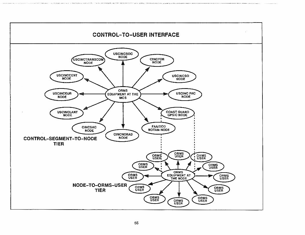
CONTROL-TO-USER INTERFACE
CONTROL-SEGMENT-TO-NODE TIER
55
~ ~ ~ ~ ORMS USER
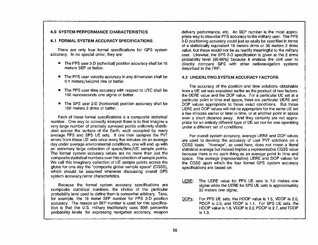
4.0 SYSTEM PERFORMANCE CHARACTERISTICS
4.1 FORMAL SYSTEM ACCURACY SPECIFICATIONS
There are only four formal specifications for GPS system accuracy. In no special order, they are:
• The PPS user 3-0 (spherical) position accuracy shall be 16 meters SEP or better.
• The PPS user velocity accuracy in any dimension shall be 0.1 meters/second rms or better.
• The PPS user time accuracy with respect to UTC shall be 100 nanoseconds one sigma or better.
• The SPS user 2-0 (horizontal) position accuracy shall be 100 meters 2 d rms or better.
Each of these formal specifications is a composite statistical number. One way to correctly interpret them is to first imagine a very large number of precisely surveyed points uniformly distributed across the surface of the Earth, each occupied by many average PPS and SPS UE sets. If one then samples the PVT errors from these UE sets once every five minutes on an average day under average environmental conditions, one will end up with an extremely large collection of space/time/UE sample points. The formal system accuracy values are no more than just the composite statistical numbers over this collection of sample points. We call this imaginary collection of UE sample points across the globe for one day the "composite global sample space" (CGSS), which should be assumed whenever discussing overall GPS system accuracy/ error characteristics.
Because the formal system accuracy specifications are composite statistical numbers, the choice of the particular probability level used to define them is somewhat arbitrary. Take, for example, the 16 meter SEP number for PPS 3-0 position accuracy. The reason an SEP number is used for this specification is that the U.S. military traditionally uses 50th percentile probability levels for expressing navigation accuracy, weapon
56
delivery performance, etc. An SEP number is the most appropriate way to describe PPS accuracy to the military user. The PPS 3-0 positioning accuracy could just as easily be specified in terms of a statistically equivalent 18 meters drms or 36 meters 2 drms value, but these would not be as readily meaningful to the military user. Likewise, the SPS 2-0 specification is given at the 2 drms probability level (95-98%) because it enables the civil user to directly compare GPS with other radionavigation systems described in the FRP.
4.2 UNDERLYING SYSTEM ACCURACY FACTORS
The accuracy of the position and time solutions obtainable from a UE set was explained earlier as the product of two factors: the UERE value and the OOP value. For a particular UE set at a particular point in time and space, there are particular UERE and DOP values appropriate to those exact conditions. But those UERE and DOP values will not be appropriate for the same UE set a few minutes earlier or later in time, or at another point in space even a short distance away. And they certainly are not appropriate for an entirely different type of UE set nor for one operating under a different set of conditions.
For overall system accuracy, average UERE and DOP values are used to develop the accuracy of user PVT solutions on a CGSS basis. "Average", as used here, does not mean a literal statistical average but instead implies a representative CGSS value because there is no such thing as an average point in time and space. The average (representative) UERE and OOP values for the CGSS upon which the four formal GPS system accuracy specifications are based on:
UERE: The UERE value for PPS UE sets is 7.0 meters one sigma while the UERE for SPS UE sets is approximately 32 meters one sigma.
OOPs: For PPS UE sets, the HOOP value is 1.5, VOOP is 2.0, POOP is 2.5, and TOOP is 1.1. For SPS UE sets, the HOOP value is 1.6, VOOP is 2.2, POOP is 2.7, and TOOP is 1.3.

FOUR FORMAL SYSTEM ACCURACY SPECIFICATIONS
FOUR FORMAL SPECIFICATIONS STATISTICALLY EQUIVALENT TO:
PPS POSITION 16 m SEP ,.. 18 m drms, 36 m 2 drms
PPS VELOCITY 0.1 m/sec ,.. 0.07 m/sec LEP, 0.2 m/sec 2 drms
PPS UTCTIME 100 nsec one-sigma ... 68 nsec TEP, 200 nsec 2 drms
SPS POSITION 100 m 2 drms
UNDERLYING FACTORS:
AVERAGE PPS UERE ~
AVERAGE PPS OOPS
AVERAGE SPS UERE
AVERAGE SPS OOPS
,.. 40 m CEP, 50 m drms
"AVERAGES" FOR THE COMPOSITE GLOBAL
SAMPLE SPACE {CGSS):
• OVER THE ENTIRE GLOBE
• OVER AN ENTIRE DAY
• REPRESENTATIVE PPS & SPS UE SETS
57
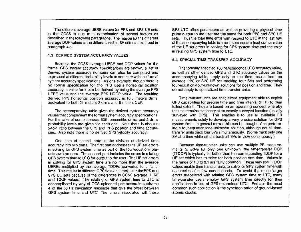
The different average UERE values for PPS and SPS UE sets in the CGSS is due to a combination of several factors as described in the following paragraphs. The reason for the different average DOP values is the different visible-SV criteria described in paragraph 4.6.
4.3 DERIVED SYSTEM ACCURACY VALUES
Because the CGSS average UERE and DOP values for the formal GPS system accuracy specifications are known, a set of derived system accuracy numbers can also be computed and expressed at different probability levels to compare with the formal system accuracy specifications. As one example, though there is no formal specification for the PPS user's horizontal position accuracy, a value for it can be derived by using the average PPS UERE value and the average PPS HOOP value. The resulting derived PPS horizontal position accuracy is 10.5 meters drms, equivalent to both 21 meters 2 drms and 8 meters CEP.
The accompanying table gives the derived system accuracy values that complement the formal system accuracy specifications. For the sake of completeness, 50th percentile, drms, and 2 drms probability levels are given for each one. Note there is about a 5-to-1 ratio between the SPS and PPS position and time accuracies. Also note there is no derived SPS velocity accuracy.
One item of special note is the division of derived time accuracy into two parts. The first part addresses the UE set errors in solving for GPS system time as part of the four~equation/fourunknown process. The second part includes the errors in relating GPS system time to UTC for output to the user. The UE set errors in solving for GPS system time are no more than the average UEREs multiplied by the average TDOPs converted to units of time. This results in different GPS time accuracies for the PPS and SPS UE sets because of the differences in CGSS average UERE and TOOP values. The relating of GPS system time to UTC is accomplished by way of OCS-uploaded parameters in subframe 4 of the 50 Hz navigation message that give the offset between GPS system time and UTC. The errors associated with these
58
GPS-UTC offset parameters as well as providing a physical time pulse output to the user are the same for both PPS and SPS UE sets. Thus the total time error with respect to UTC in the last row of the accompanying table is a root-sum-square (rss) combination of the UE set errors in solving for GPS system time and the error in relating GPS system time to UTC.
4.4 SPECIAL TIME-TRANSFER ACCURACY
The formally specified 100 nanoseconds UTC accuracy value, as well as other derived GPS and UTC accuracy values on the accompanying table, apply only to the time results from an average PPS or SPS UE set tracking four SVs and performing four-equation/four-unknown solutions for position and time. They do not apply to specialized time-transfer units.
Time-transfer units are specialized equipment able to exploit GPS capabilities for precise time and time interval (PTTI) to their fullest extent. They are based on an operating concept whereby the unit remains stationary at an exactly surveyed location (usually surveyed with GPS). This enables it to use all available PR measurements solely to develop a very precise solution for GPS system time. In general terms, this can be thought of as performing a four-equation/one-unknown solution, although not all timetransfer units track four SVs simultaneously. (Some track only one SV at a time while others track all SVs in view continuously.)
Because time-transfer units can use multiple PR measurements to solve for only one unknown, the time-transfer DOP (TTDOP) is typically far better than the corresponding TOOP for a UE set which has to solve for both position and time. Values in the range of 1.0 to 0.1 are fairly common. These very low TTOOP values enable time-transfer units to solve for GPS system time with accuracies of a few nanoseconds. To avoid the much larger errors associated with relating GPS system time to UTC, many time-transfer users employ GPS system time directly for their applications in lieu of GPS-determined UTC. Perhaps the most common such application is the synchronization of ground-based atomic clocks.
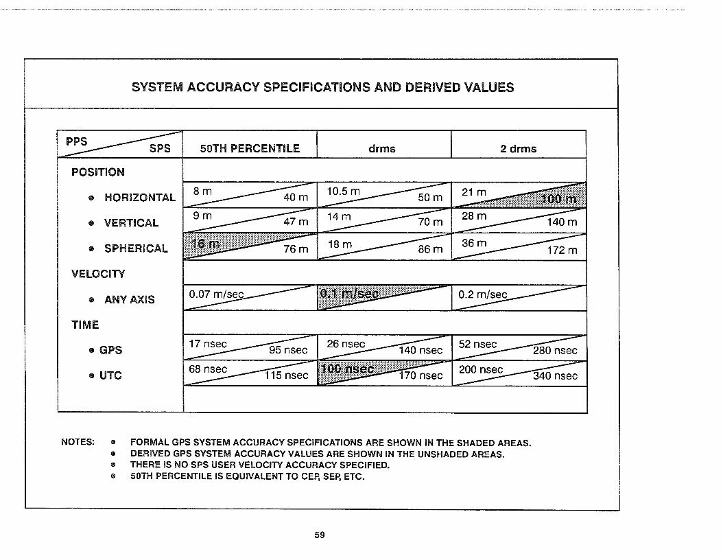
SYSTEM ACCURACY SPECIFICATIONS AND DERIVED VALUES
50TH PERCENTILE drms 2 drms
POSITION
• HORIZONTAL
• VERTICAL
• SPHERICAL \iij\l\.llll!lllii!ii!!J!jjjji!j!j!J!]j]J\it??'''''''''''';'~·~
VELOCITY
• ANY AXIS
TIME
• GPS
• UTC
NOTES: • FORMAL GPS SYSTEM ACCURACY SPECIFICATIONS ARE SHOWN IN THE SHADED AREAS. e DERIVED GPS SYSTEM ACCURACY VALUES ARE SHOWN IN THE UNSHADED AREAS. • THERE IS NO SPS USER VELOCITY ACCURACY SPECIFIED. • 50TH PERCENTILE IS EQUIVALENT TO CEP, SEP, ETC.
59

4.5 SYSTEM ACCURACY ASSUMPTIONS AND EXCEPTIONS
Just as the four formal GPS system accuracy specifications were based on average UERE and DOP values for the CGSS-the average UERE and DOP values are themselves dependent on several standard system operating assumptions. Each of these assumptions is (or will be) generally true, but there can be significant exceptions from time to time or under certain circumstances. These exceptions form the basis for many important system performance characteristics.
Not all exceptions to the standard system operating assumptions are necessarily bad. The assumptions are conservative in nature and it is quite possible for exceptions to result in improved system performance. This is especially true for UE sets designed to take advantage of aiding information from external sources or specialized UE sets designed to achieve ultimate P, V, or T accuracies. Since there are so many different types of UE sets, the standard assumptions presume the use of relatively simple, low-cost PPS and SPS UE sets as described in Section 5. If you have a specialized UE set, you are probably already aware that the formal GPS system accuracy specifications do not apply to the performance of your UE set anyway.
Before covering the standard system operating assumptions and their important exceptions, a customary division of the average UERE values into two portions needs to be explained. For many reasons, UERE values are normally broken out into those errors contributed by the Space and Control Segments and those contributed by the User Segment. The line dividing these two portions of the UERE is at the SV's SIS output antenna. The Space and Control Segment contribution to the UERE includes instability of the SV clock, unpredictability of the SV orbit, and errors in the broadcast 50 Hz navigation messages. The User Segment contribution to the UERE includes things like imprecision of the UE set's PRN sequence tracking design and errors in its correction of the PR measurements for atmospheric delays. These two portions of the UERE combine together in a rss fashion to give the total average UERE.
60
The standard system operating assumptions with important exceptions that affect users are listed below and detailed in the following pages.
• The OCS is functioning nominally and is routinely uploading 50 Hz navigation message data that result in an average contribution to the UERE from each SV of 6.0 meters one sigma for the PPS and about 29 meters one sigma for the SPS.
• There are 21 identical, nominally operating Block II Navstar SVs in their defined orbital locations.
• The PPS UE sets are able to select the best set of four SVs for their position/time solution from among all SVs visible at their location which are at least 5.0 degrees above the local horizon. The corresponding assumption for SPS UE sets is the same except the minimum SV elevation angle is 7.5 degrees.
• Both types of UE sets are operating in a nominal standalone mode (without external aiding input from any source). The level of jamming is such that the UE sets are able to maintain track on their four selected SVs.
• The PPS users are operating in a full PPS mode (a PPScapable UE set with PPS keys inserted) and are able to track P(Y)-code on both the L 1 and L2 signals for deterministically correcting the ionospheric delay with a dualfrequency measurement model. The SPS users are assumed to only be able to track C/A-code on the L1 $ignal and so must use the single-frequency ionospheric delay model based on the terms in subframes 4/5 of the 50 Hz navigation message.
• The PPS UE set contributes 3.7 meters one sigma to the PPS UERE while the SPS UE set implementation contributes 14 meters one sigma to the SPS UERE.
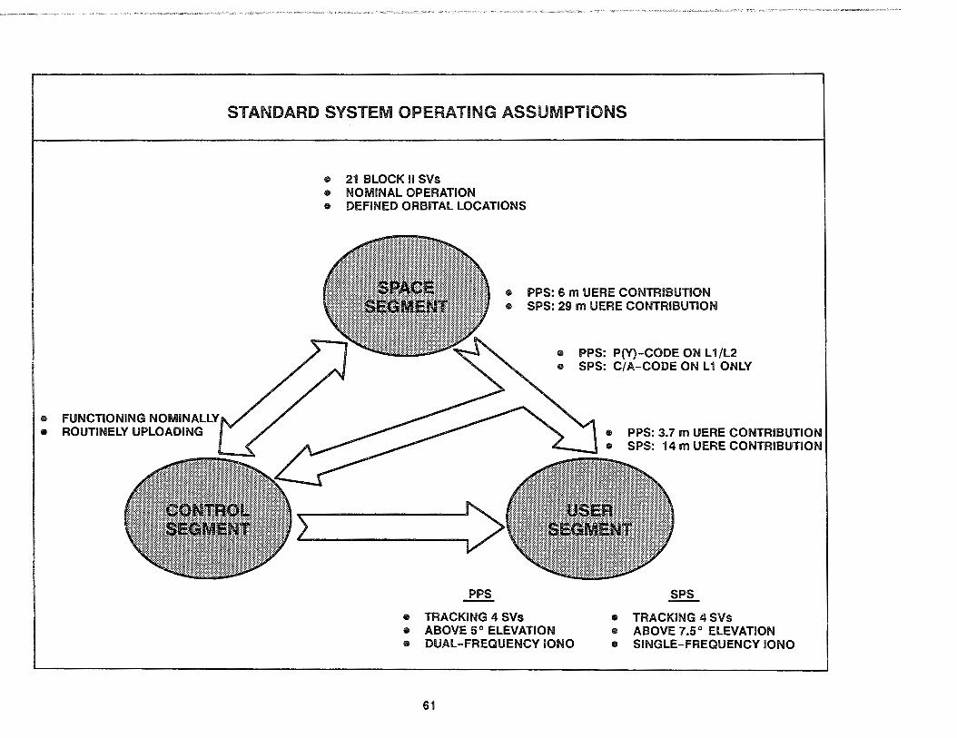
e FUNCTIONING NOMINALLY • ROUTINELY UPLOADING
STANDARD SYSTEM OPERATING ASSUMPTIONS
e 2i BLOCK II SVs • NOMINAL OPERATION • DEFINED ORBITAL LOCATIONS
e PPS: 6 m UERE CONTRIBUTION e SPS: 29 m UERE CONTRIBUTION
~
• TRACKING 4 SVs • ABOVE 5° ELEVATION
• PPS: PM-CODE ON Li /L2 • SPS: C/ A-CODE ON Li ONLY
o PPS: 3.7 m UERE CONTRIBUTION ----- e SPS: 14 m UERE CONTRIBUTION
SPS
• TRACKING 4 SVs • ABOVE 7.5° ELEVATION
• DUAL-FREQUENCY IONO e SINGLE-FREQUENCY !ONO
61
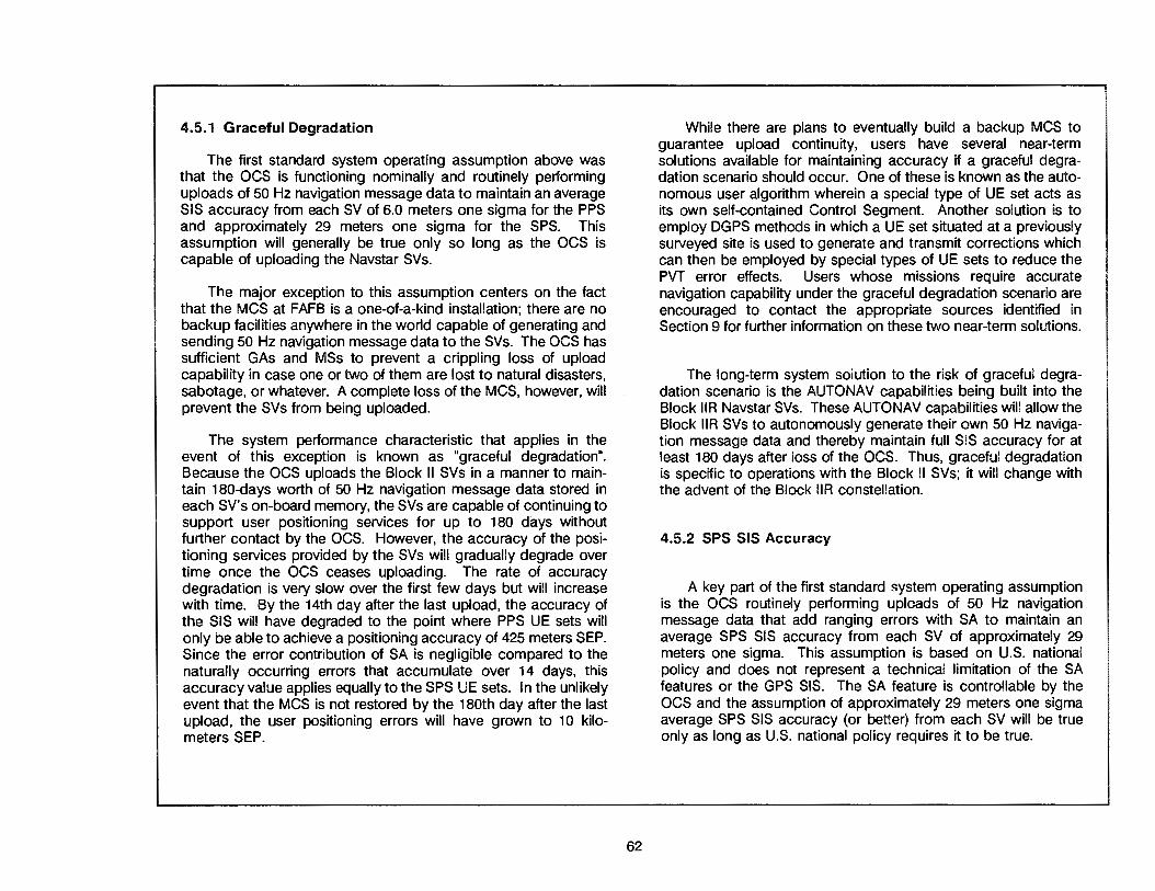
4.5.1 Graceful Degradation
The first standard system operating assumption above was that the OCS is functioning nominally and routinely performing uploads of 50 Hz navigation message data to maintain an average SIS accuracy from each SV of 6.0 meters one sigma for the PPS and approximately 29 meters one sigma for the SPS. This assumption will generally be true only so long as the OCS is capable of uploading the Navstar SVs.
The major exception to this assumption centers on the fact that the MCS at FAFB is a one-of-a-kind installation; there are no backup facilities anywhere in the world capable of generating and sending 50 Hz navigation message data to the SVs. The OCS has sufficient GAs and MSs to prevent a crippling loss of upload capability in case one or two of them are lost to natural disasters, sabotage, or whatever. A complete loss of the MCS, however, will prevent the SVs from being uploaded.
The system performance characteristic that applies in the event of this exception is known as "graceful degradation". Because the OCS uploads the Block II SVs in a manner to maintain 180-days worth of 50 Hz navigation message data stored in each SV's on-board memory, the SVs are capable of continuing to support user positioning services for up to 180 days without further contact by the OCS. However, the accuracy of the positioning services provided by the SVs will gradually degrade over time once the OCS ceases uploading. The rate of accuracy degradation is very slow over the first few days but will increase with time. By the 14th day after the last upload, the accuracy of the SIS will have degraded to the point where PPS UE sets will only be able to achieve a positioning accuracy of 425 meters SEP. Since the error contribution of SA is negligible compared to the naturally occurring errors that accumulate over 14 days, this accuracy value applies equally to the SPS UE sets. In the unlikely event that the MCS is not restored by the 180th day after the last upload, the user positioning errors will have grown to 1 O kilometers SEP.
62
While there are plans to eventually build a backup MCS to guarantee upload continuity, users have several near-term solutions available for maintaining accuracy if a graceful degradation scenario should occur. One of these is known as the autonomous user algorithm wherein a special type of UE set acts as its own self-contained Control Segment. Another solution is to employ DGPS methods in which a UE set situated at a previously surveyed site is used to generate and transmit corrections which can then be employed by special types of UE sets to reduce the PVT error effects. Users whose missions require accurate navigation capability under the graceful degradation scenario are encouraged to contact the appropriate sources identified in Section 9 for further information on these two near-term solutions.
The long-term system solution to the risk of graceful degradation scenario is the AUTONAV capabilities being built into the Block llR Navstar SVs. These AUTONAV capabilities will allow the Block llR SVs to autonomously generate their own 50 Hz navigation message data and thereby maintain full SIS accuracy for at least 180 days after loss of the OCS. Thus, graceful degradation is specific to operations with the Block II SVs; it will change with the advent of the Block llR constellation.
4.5.2 SPS SIS Accuracy
A key part of the first standard system operating assumption is the OCS routinely performing uploads of 50 Hz navigation message data that add ranging errors with SA to maintain an average SPS SIS accuracy from each SV of approximately 29 meters one sigma. This assumption is based on U.S. national policy and does not represent a technical limitation of the SA features or the GPS SIS. The SA feature is controllable by the OCS and the assumption of approximately 29 meters one sigma average SPS SIS accuracy (or better) from each SV will be true only as long as U.S. national policy requires it to be true.
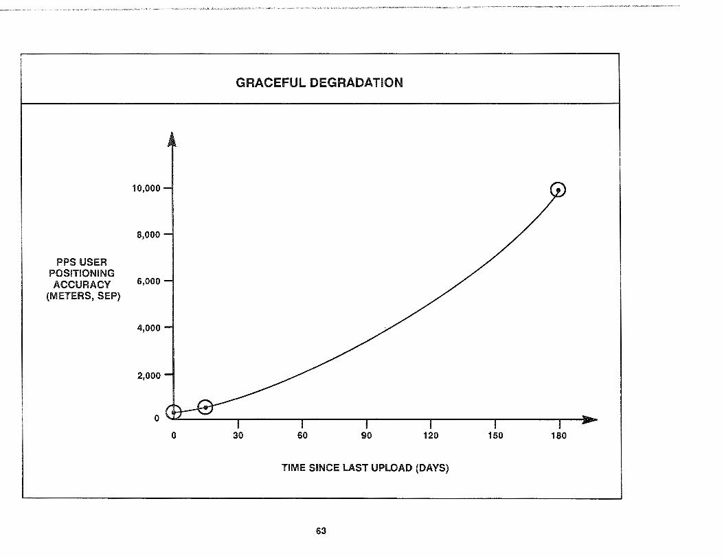
PPS USER POSITIONING
10,000
8,000
ACCURACY 5,ooo (METERS, SEP)
4,000
2,000
0
0
GRACEFUL DEGRADATION
30 60 90 120 150 180
TIME SINCE LAST UPLOAD (DAYS)
63

4.5.3 System Availability
The second identified standard system operating assumption was that 21 identical, nominally operating Navstar SVs are in their defined orbital locations. This assumption should hold true most of the time since the on-orbit constellation is actually planned as 21 SVs plus 3 operational spare SVs. The 3 operational spare SVs are included in the on-orbit constellation for the express purpose of backing up the optimally located 21 SVs in the event that one or more of them becomes incapable of providing the SIS interface needed to support the user positioning service.
There is a formal GPS system specification corresponding closely to this standard operating condition assumption. This is the specification for "system availability" which is stipulated in GPS program documentation as:
"System availability shall be at least 98%, where system availability is defined as the probability that a minimum of 18 satellites will be operational at any time and broadcasting current navigation messages."
The reason this system availability specification addresses 18 SVs instead of a 21 SV constellation is historical in nature. During the 1970s, the original baseline Navstar constellation was developed with a total of 24 SVs arrayed in 3 planes of 8 SVs each to guarantee continuous positioning service availability to users anywhere on the globe. However, due to budgetary constraints in the early 1980s, this robust number of SVs had to be reduced to the absolute bare minimum number possible. This cut-back resulted in a redesigned baseline constellation consisting of 18 SVs arrayed in 6 planes of 3 SVs each. Although this minimalist constellation met the budget requirements and provided a reasonable level of user positioning service, it had zero margin for error; the loss of just one SV would result in major gaps in coverage.
64
The formal 98% system availability specification was subsequently developed for this rebaselined constellation as the required probability of having at least the minimum number of nominally operating SVs on orbit needed for reasonable positioning service coverage. This did not mean that 18 SVs was sufficient to guarantee users would always have four visible SVs with good DOP at every possible time/location point in the CGSS. With 18 SVs, there would still be short-duration gaps (one-half hour) in the coverage at certain mid-latitude points around the globe, but this was considered a reasonable level of service under the strict budgetary constraints of the early 1980s.
Because of the system availability requirement to ensure at least 18 nominally operating SVs on orbit 98% of the time, approval was sought-and ultimately received-to augment the 18-SV constellation with on-orbit active spare SVs. It was determined that 3 spare SVs would be needed based on the expected annual failure rate for 18 on-orbit SVs. With a mean mission duration for the Block II SVs of 6 years and with 18+3 SVs on orbit, an average of 18+3 end-of-life SV failures should be expected in every 6-year period (about 3.5 SV failures per year). Furthermore, by factoring in the periodic but temporary interruptions all SVs are subject to (e.g., downtime for orbital position-keeping maneuvers, atomic clock maintenance, and other SV housekeeping activities), a total of 21 SVs were found to be needed in order to have a 98% probability that 18 of them would be working at any time.
In March of 1988, the Air Force committed to support an operational constellation of 21 SVs plus 3 spares as soon as practical. However, it was recognized that a revised system availability requirement could not be met since the Block II SV assets had not been programmed against a 21 +3 SV constellation requirement. Thus the formal system availability requirement has not yet been revised even though the constellation deployment plans were modified to reflect a 21-SV constellation which will evolve into the 21 + 3 configuration.
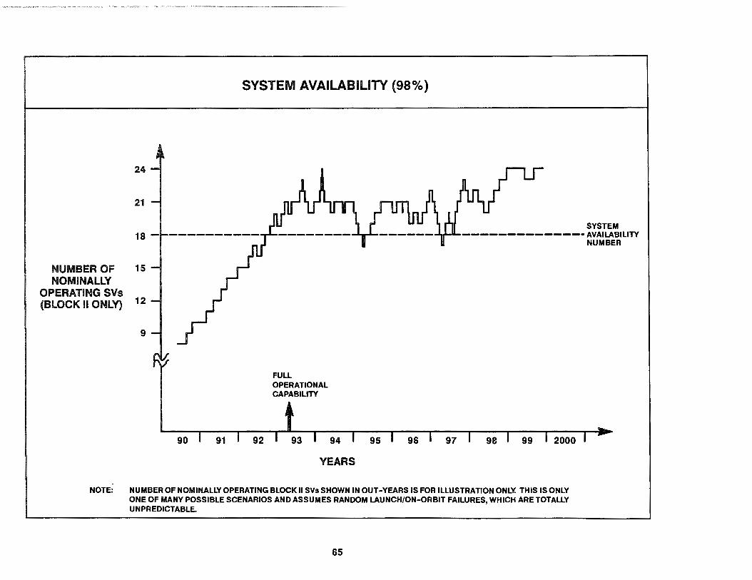
SYSTEM AVAILABILITY (98%)
24
21
SYSTEM 18 - --------------AVAILABILITY
NUMBER OF NOMINALLY
OPERATING SVs {BLOCK II ONLY)
15
12
9
90 91 92
FULL OPERATIONAL CAPABILITY
93 94
YEARS
95 96 97 98 99 2000
NOTE: NUMBER OF NOMINALLY OPERATING BLOCK II SVs SHOWN IN OUT-YEARS IS FOR ILLUSTRATION ONLY. THIS IS ONLY ONE OF MANY POSSIBLE SCENARIOS AND ASSUMES RANDOM LAUNCH/ON-ORBIT FAILURES, WHICH ARE TOTALLY UNPREDICTABLE.
65
NUMBER

4.5.4 Positioning Service Coverage
The standard system operating assumption of 21 nominally operating Navstar SVs in their defined orbital locations was selected as a middle-of-the-road benchmark. It does not reflect the improved system performance that results from the 3 operational spare SVs in the 21 +3 constellation. But it does reflect the improved performance that results from an optimized set of orbital locations used for the 21-SV constellation as compared to the locations originally planned for the 18 + 3 SV constellation. This set of orbital locations for the 21-SV constellation is known as the "optimal-21" design, and it is distinctly different from the set of locations for both the 18+3 and the 21 +3 designs.
The definition of "positioning service coverage" is quite different from the definition of "system availability". In fact, positioning service coverage is really what most users have in mind when they consider whether or not GPS is available to them. Whereas system availability is a measure of how likely it is a certain number of operational SVs will be on orbit; positioning service coverage is a measure of how likely it is you will receive adequate service from the on-orbit SVs.
4.5.4.1 Constellation Value
The positioning service coverage of GPS is measured in terms of a number known as the "constellation value". The constellation value is generally defined as the fraction of all possible time/ location points in the CGSS that have four visible SVs with a good enough OOP to allow accurate PVT solutions. A constellation value of 1.00 means users always have four visible SVs with a good enough OOP no matter when or where they choose to operate. A constellation value less than 1.00 means there are certain points in time at certain locations for which there are either three or fewer SVs visible or the four or more SVs visible will not provide a good enough OOP.
There are constellation values for both 3-0 and 2-0 coverage. A "good enough OOP" is customarily defined as a POOP less than
66
or equal to 6.0 for the 3-0 constellation value and an HOOP less than or equal to 4.0 for the 2-0 constellation value. In both cases, these OOP threshold values are based on a completely unaided (stand-alone) four-SV UE set position solution.
The 6.0 and 4.0 threshold definitions for "good enough OOP" were originally somewhat arbitrary, but they have since become standardized as an essential part of the constellation value definitions. They must be taken with a grain of salt, however, since under average PPS UERE conditions, the POOP threshold of 6.0 results in a 38 m SEP spherical positioning accuracy being defined as not good enough while the HOOP threshold of 4.0 will do the same for a horizontal positioning accuracy of 24 m CEP. In comparison with other navigation systems, it is difficult to accept a 38 m SEP spherical accuracy or a 24 m CEP horizontal accuracy as not being good enough to use, but it is a result of the standard definitions for the constellation values.
With the optimal-21 constellation (not including any spares), the 3-0 constellation value will be 0.9999 and the 2-0 constellation value will be nearly 1.000 for an average PPS UE set able to select and track SVs 5 degrees or more above the local horizon. For the average SPS UE set, which only tracks SVs 7.5 degrees or more above the horizon, the corresponding constellation values will be 0.9980 and 0.9992. These numbers are the probabilities that, at a randomly chosen time and location, the UE set will find four visible SVs with good DOP.
Because these constellation values are quite high, users need not worry too much about whether their UE set will find four visible SVs with good OOP whenever and wherever required as long as there are 21 nominally operating Navstar SVs in their defined orbital locations. However, since there is a significant probability of SV failures (on average, 3.5 failures per year) and there are also periodic but temporary SV interruptions, there will not always be 21 normally operating Navstar SVs in their defined orbital locations. Users thus run a small risk of not finding four SVs with good OOP available. The accompanying diagram shows the effect of SV outages on the PPS 3-0 constellation value.
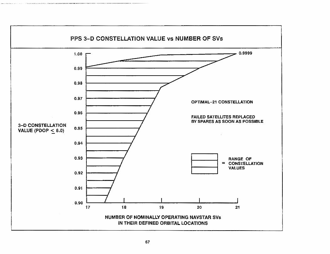
3-D CONSTELLATION VALUE (POOP ~ 6.0)
PPS 3-D CONSTELLATION VALUE vs NUMBER OF SVs
1.00
0.99
0.98
0.97
0.96
0.95
0.94
0.93
0.92
0.91
0.90 17
~--=================:::::::::;;:::;"" 0.9999
18 19
OPTIMAL-21 CONSTELLATION
FAILED SATELLITES REPLACED BY SPARES AS SOON AS POSSIBLE
§= 20
RANGE OF CONSTELLATION VALUES
21
NUMBER OF NOMINALLY OPERATING NAVSTAR SVs IN THEIR DEFINED ORBITAL LOCATIONS
67

4.5.4.2 Coverage as a Function of Time
The constellation values just discussed are useful for describing GPS positioning service coverage from an overall system perspective, but they are not well suited for application by an individual user. Unlike the system operator who tries to support users at every possible time/location point in the CGSS, individual users are normally only interested in their coverage at a particular point in space. These points might be targets to be bombed, narrow channels to be negotiated, survey sites to be occupied, or airfields to be landed at. Regardless of the nature of the particular point in space, users are interested in the coverage as a function of time.
In the early days of the GPS program when there were only a few on-orbit Navstar SVs, the best way to conceptualize the positioning service coverage as a function of time was in terms of the daily "four-satellite good DOP windows" or simply the "coverage windows". This was particularly appropriate during the Phase I and II testing conducted at YPG since the orbital positions of the Block I SVs had been selected so the SVs would rise one after the other in the sky over Yuma at roughly the same time each day. In general terms, the coverage window would start whenever the fourth SV rose above the local horizon mask angle (5 degrees for PPS, 7.5 degrees for SPS) and the resulting HOOP or PDOP value fell below the 4.0 or 6.0 threshold for good DOP. The coverage windows would then remain open as the various SVs rose and set until there were only three SVs remaining visible in the sky.
Because the Block I SVs (and now the Block II SVs) are placed in orbits that give them repeating ground tracks and because the OCS tightly controls their positions relative to one another, the pattern of SVs rising and setting each day during the coverage windows repeats almost identically. And since the DOP values depend only on the relative geometry between the SVs and the user, the DOP values also repeat almost identically during the coverage windows.
68
This day-to-day repeatability of the coverage windows was (and still is) a major characteristic of GPS which most users find important to their mission planning. However, it must be emphasized that even though the coverage windows repeat each day, they do not repeat at exactly the same time every day. Because of the repeating ground track orbit used for the SVs, the SVs rise and set in their particular pattern every 23 hours and 56 minutes. Thus, the coverage windows will start and end four minutes earlier on each succeeding day. This time-shift effect often surprises many users since the four minutes earlier each day accumulate and what was once a convenient coverage window starting mid-morning precesses to become a coverage window beginning well before dawn.
As more SVs are launched, user concerns are gradually changing from worrying about coverage windows to worrying about "DOP holes". This is natural. As the constellation values improve and the coverage windows grow longer, it makes more sense to focus on the ever-shorter periods of insufficient coverage. (yery much like the switch in perspectives between thinking "the glass is half-full" to thinking ''the glass is half-empty".) Just like the coverage windows, the DOP holes also repeat, shifting four minutes earlier each day.
The anatomy of a DOP hole can vary greatly. Some of them are not very "deep" (a misnomer, since the DOP values actually rise to cause the "hole"). In shallow DOP holes, the accuracy degradation is minimal-usually only slightly worse than 24 meter CEP horizontal accuracy or 38 meter SEP spherical accuracy. Some of them are very abrupt in start or finish (usually those caused by fewer than four SVs being visible during the DOP hole), while others are characterized by gradual transitions (those due to poor geometry).
Remember that, like the DOP thresholds used for constellation values, the threshold values for DOP holes are assumed to be based on a completely unaided (stand-alone) four-SV UE position solution. In most DOP hole circumstances, external aiding will be extremely effective in countering the ensuing accuracy degradation.

TEST SITE
15 HI§------.
12 a. g 9 :c
a. 0 c :c
6
3
15
12
9
6
3
0:00
TEST SITE
0:00
COVERAGE AS A FUNCTION OF TIME
COVERAGE WINDOW
6:00
6:00
DOP HOLE
I HOOP GRAPH I
12:00
I HOOP GRAPH I
12:00
69
18:00
18:00
1SEP86
----------- HOOP :5 4.0 THRESHOLD
0:00
31MAR91
------------ HOOP :5 4.0 THRESHOLD
0:00

4.5.4.3 Coverage as a Function of location
Even when there are fewer than 21 nominally operating Navstar SVs in their defined orbital locations, GPS will provide continuous coverage for most users around the globe. The DOP holes will occur for short durations at only a few scattered locations. And in those regions where DOP holes do occur, the degraded accuracy will be experienced only by users when relying solely on a four-SV position solution. The DOP hole is not a serious problem for users who have additional position, altitude, or velocity information from an external aiding sensor which will allow the UE set to "coast" through the DOP hole.
In contrast to thinking about the coverage windows as a function of time for a particular point in space, another way to think about them is in terms of the spatial regions where DOP holes occur at some time during the day. (As used here, a "day'' really means the 23-hour, 56-minute repetition period of the coverage windows/ DOP holes.) When occurrences of these DOP holes over a day are plotted on a map, they become the daily composite geographic coverage map for the particular set of normally operating SVs. Because the SV orbits have repeating ground tracks, the locations of the geographic holes stay fixed from day to day as long as the set of nominally operating SVs and their relative orbital locations do not change. The OCS will usually reposition a spare SV in the event of a failure in one of the optimally positioned SVs, thus causing the map to change from one day to another during the repositioning period.
As an example of a daily composite geographic coverage map, the regions of degraded 2-D coverage resulting from the optimal-21 constellation with one failed SV are illustrated on the accompanying page. The one failed SV was selected at random, so this particular daily composite 2-D geographic coverage map should be considered as being only a representative illustration of the effect of a failed SV. If instead, a different failed SV had been selected to generate this illustration, the daily composite 2-D
70
geographic coverage map would look quite different. It was necessary to assume an SV had failed for this illustration because the daily composite 2-D geographic coverage map that corresponds to the standard system operating assumption of 21 nominally operating satellites SVs in their defined orbital locations has no significant regions of degraded coverage to portray.
The shaded areas shown on the accompanying page are regions in which the HDOP value exceeds 4.0, considering those SVs which are 5 degrees or more above the local horizon (the same conditions as for the PPS 2-D constellation value). These regions normally experience large HDOP values for only short periods of time. The longest period that HDOP exceeds 4.0 at any one point is about 30 minutes. Generally, the degraded coverage periods occur twice per day at the indicated locations. One DOP hole occurrence generally peaks at some small value (e.g., a HDOP between 4 and 1 O) and the other at a larger value.
The daily composite geographic coverage maps that describe the PPS 3-D and SPS 3-D and 2-D coverages are generally similar to the corresponding PPS 2-D map. Although the overall character of the DOP holes stays basically the same, the exact size and shape of the regions of degraded coverage vary slightly. For this reason, higher headquarter planners who need to coordinate movements of a large number of users will often use theater-scale maps on which to portray the exact bounds of the degraded coverage region for the specific type of UE set in use (see paragraph 5.3).
Poor UE set performance can be due to causes other than SV geometry and degraded coverage. This includes such factors as equipment malfunction, signal jamming, terrain shadowing, etc. These types of performance degradations will also benefit from external aiding by other navigation systems, and can sometimes be ameliorated by user action.

COVERAGE AS A FUNCTION OF LOCATION
180° 150° 120° goo 60° 30° 00 30° 60° goo 120° 150° 180°
c;:f~o
60° 60°
JQO
.'
. " :,
30° 30°
60° 60°
100° 150° 1200 goo 60° 30° oo 30° 600 goo 1200 150° 1000
71

4.6 SV SELECTION BY THE UE
Another standard GPS system operating assumption was that PPS UE sets select the best set of four Navstar SVs to use for their position/time solution from amongst all visible SVs which are at least 5.0 degrees above the local horizon. The corresponding assumption for SPS UE sets was the same except the minimum SV elevation is 7.5 degrees.
It is a basic GPS principle that all UE sets autonomously select which SV signals to track; no user involvement is required (nor even allowed in most cases). In order to perform the SV selection process, the UE set must first have a basic knowledge of the SVs in orbit. This includes what the SV PRN codes are, which are operating nominally, and where they are in their orbits. The UE set gets this information directly from the almanac data in subframes 4/5 of the SV-broadcast navigation message. Once the UE set has this almanac information, it uses knowledge about its current position and time (either stored in its internal memory or input by the user) to determine which SVs should be visible in the sky overhead and what their relative geometry is. The UE set will then select the best set of four SVs to track.
An important GPS principle to note is that the definition of "best" set of four SVs to track often differs depending on the intended purpose of the particular UE set. To explain: generalpurpose UE sets often select their best set based on the visible four-SV combination that results in the lowest GOOP value, thus optimizing the 3-0 position and time accuracy equally. On the other hand, UE sets intended for naval operations are usually designed to select their best set based on the four-SV combination that results in the lowest HOOP, since vertical position and time accuracy are less important in seaborne navigation. As long as there are more than four SVs visible, there may be many different "best" combinations of four SVs.
Another important principle to note is that PPS and SPS UE sets have different specifications for tracking SVs that are low on the horizon. This is not related to the SIS power levels which
72
are adequate to allow PPS and SPS signal tracking down to the horizon. Rather, it is due to the PPS and SPS UE sets using different means of compensating for atmospheric distortions of the SIS. At low elevation angles (the angle between the SV and the horizon), the SIS is subject to significant path bending and delays caused by atmospheric distortions; the effects are similar to the way stars twinkle as a result of atmospheric distortion of their light. The troposphere causes path bending that can be partially compensated for by using mathematical models for the average water vapor content of the troposphere. The ionosphere causes path delays that can be partially compensated for by using models based either on some forecast number of electrons in the ionosphere (the single-frequency ionospheric delay model), or on an actual calculation of the number of electrons in the ionosphere using simultaneous measurements from both the L 1 and L2 signals (the dual-frequency ionospheric measurement model). The compensation accuracy of the tropospheric model and the two ionospheric models degrades as the SIS has to pass through more of the atmosphere on its way to the UE set antenna. Thus, the models are most accurate when the SVs are directly overhead and worst when the SVs are at low elevation angles.
Most (but not all) SPS UE sets are only able to track the L 1 signal and so cannot employ the dual-frequency ionospheric measurement model. Instead, they must rely on the singlefrequency ionospheric delay model, which uses forecast terms contained in subframes 4/5 of the SV-broadcast navigation message and is much less accurate at low elevation angles. By artificially restricting the tracking of SVs to those above some minimum elevation angle, a single-frequency SPS UE set can prevent an excessive buildup of ionospheric delay compensation errors in its PR measurements. A 7.5-degree mask angle for SPS UE sets is fairly standard although some restrict their tracking to SVs above 1 O degrees. The same also holds true for dualfrequency PPS UE sets, but because of the higher inherent accuracy of the dual-frequency ionospheric measurement model, dual-frequency PPS UE sets can track down to a lower minimum mask angle (5 degrees) without incurring excessive PR errors.
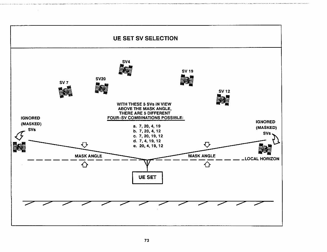
IGNORED (MASKED)
.(f' SVs
M
SV7
\fl
0
SV20
tf
UE SET SV SELECTION
SV4
if
WITH THESE 5 SVs IN VIEW ABOVE THE MASK ANGLE, THERE ARE 5 DIFFERENT
sv 19
- sv 12
-FOUR-SV COMBINATIONS POSSIBLE:
IGNORED a. 7, 20, 4, 19 (MASKED) b. 7,
2200, 4, 12 SVst
c. 7, '19, 12 d. 7, 4, 19, 12
e. 20,4, 19, 12 -
M~K~G~ . ~......,.i:-;_ - - - - - - - - - _LOCAL HORIZON
0
UESET
73
4.1 RESISTANCE TO INTERFERENCE (SURVIVABILITY)
The next two interrelated standard system operating assumptions were that the UE sets are able to operate in a nominal standalone mode (without external aiding) and that the level of jamming is moderate enough for the UE sets to maintain track on the four selected Navstar SYs. These assumptions are really just a small part of the subject of GPS survivability.
Because GPS brings major force enhancements to military operations, a threat exists that a hostile power might wish to deny GPS to U.S. and allied military forces (equivalently, terrorists might want to disrupt peaceful users). As a result of this threat, GPS development efforts have long emphasized the importance of overall system survivability. Potential threats to the Space, Control and User Segments were studied and countermeasure features developed and incorporated into the system design.
Potential threats to the Space Segment include anti-satellite weapons, high-powered lasers, and particle beam weapons. GPS incorporates a constellation of 21 SYs (plus 3 spares) at high altitude with appropriate inter-SY spacing to cope with such threats by preventing multiple-SY attacks. The hostile elimination of a small number of SYs leads to only a gradual degradation of the constellation value as discussed in paragraph 4.5.4.1. Additionally, since periodic SY replacement is already planned based on natural limits imposed by the expected SY failure rate (3.5 failures per year), there will almost always be at least one replacement SY being readied for launch.
The Control Segment, composed of the MCS and several remotely located MSs and GAs, could be subject to direct enemy attack, facility sabotage, or high-energy jammers. To counter these threats, the decision was made early in the GPS program to provide redundant MSs and GAs so that deactivation of any one station will not significantly affect the OCS operational capability.
74
To cope with the jamming and spoofing threat, encryption technology is used for all ground-space telemetry, command, and control links. As discussed in paragraph 4.5.1, in the event the MCS is somehow prevented from sending updated upload data to the SVs, graceful degradation of PVT accuracy will be experienced by users of the Block II SYs. Of course, once the Block llR SYs are launched, the MCS will cease to be an item of vulnerability.
Key threats to the UE sets include electromagnetic pulse (EMP) bursts, jamming, and spoofing. UE sets destined for use in military vehicles incorporate appropriate EMP and nuclear hardening techniques. The spread-spectrum nature of the l-band SIS provides substantial resistance to jamming. Under stand-alone conditions, a P-code UE set is able to maintain track on the SYs in the presence of hostile jammer signals 41 dB greater than the SY signals. For C/A-code the resistance to jamming is 31 dB. To counter extremely high jamming environments, special adaptive array (null steering) antennas in conjunction with aiding navigation systems can be used (discussed in Section 5). Many vehicles are normally equipped with self-contained navigation systems, such as inertial systems, which will help counter short-term GPS degradation due to hostile activity. GPS survivability against spoofing is provided through the SY's ability to broadcast the A-S Y-code in lieu of the P-code and the PPS user's ability to track it. (SPS users are unable to resist spoofing since they cannot track the Y-code signals.)
Since GPS is a highly accurate space-based positioning system available to all suitably equipped users, unfriendly forces may attempt to use the system against U.S. interests during national or international conflicts. To preclude this possibility, SA features permit authorized users to navigate with full accuracy while nonauthorized users experience degraded navigation performance. The determination as to who is an authorized user is made by the U.S. Government based on national policy.
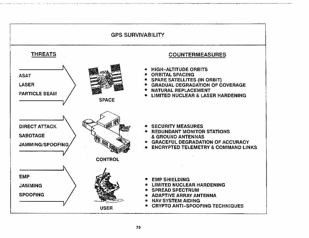
THREATS
ASAT
LASER
PARTICLE BEAM
DIRECT ATTACK
SABOTAGE
EMP
JAMMING
SPOOFING
GPS SURVIVABILITY
SPACE
CONTROL
USER
75
COUNTERMEASURES
• HIGH-ALTITUDE ORBITS • ORBITAL SPACING • SPARE SATELLITES (IN ORBIT) • GRADUAL DEGRADATION OF COVERAGE • NATURALREPLACEMENT • LIMITED NUCLEAR & LASER HARDENING
• SECURITY MEASURES • REDUNDANT MONITOR STATIONS
& GROUND ANTENNAS • GRACEFUL DEGRADATION OF ACCURACY • ENCRYPTED TELEMETRY & COMMAND LINKS
• EMP SHIELDING • LIMITED NUCLEAR HARDENING • SPREAD SPECTRUM • ADAPTIVE ARRAY ANTENNA • NAV SYSTEM AIDING • CRYPTO ANTI-SPOOFING TECHNIQUES

4.8 DIVISION BETWEEN PPS AND SPS USERS
The last two standard system operating assumptions centered on the division of users into well-defined categories of PPS users and SPS users. While users are definitely in either one category or the other based on their "authorization· status (PPS users are authorized to receive the PPS cryptokeys while the SPS users are not authorized), the assumed performance characteristics of the two categories are not absolutely firm.
One of the standard system operating assumptions was that PPS users always operate in a full PPS mode (using a PPScapable UE set with PPS keys inserted) and are able to track PMcode on both L 1 and L2 for using the dual-frequency ionospheric measurement model. Likewise, SPS users were assumed to only track the C/A-code on the L1 signal and so use the singlefrequency ionospheric delay model. These assumptions are, on average, true for representative PPS and SPS UE sets-but there are many exceptions.
A PPS-capable UE set is one that has the built-in cryptographic logic to enable encryption/decryption processing with the PPS keys. No distinction is necessarily made as to how the PPS encryption/decryption processing is applied within the UE set. For example, certain PPS-capable UE sets such as the AN/PSN-9 (see paragraph 5.1.3.8) were originally designed without the ability to track P-code and so there is no need for them to apply the PPS encryption processing for the A-S function. The AN/PSN-9 UE set does, however, use its PPS decryption processing to support the SA functions. Another example of PPS-capable UE sets that operate in a limited PPS mode are those used in geodetic survey networks which only need PPS encryption processing for real-time support of the A-S function since the SA decryption functions can all be taken care of later during post-processing at a central facility. The OCS's MSs also function this way.
76
As a general rule, we assume PPS-capable UE sets apply their PPS encryption/decryption processing for both SA and A-S functions; but as the examples just given show, this is not necessarily true. We also assume that if the A-S function is supported (i.e., the UE set has the ability to track both P- and Y-codes) then it also has the ability to track PM-codes on both L 1 and L2, but this is also not necessarily true. There are PPS UE sets with the A-S function that operate only on L 1 .
Unlike the assumptions about PPS UE sets, SPS UE set assumptions generally have far fewer exceptions. Since SPS users lack the requisite PPS cryptokeys, they can only receive the SPS level of service. This is true regardless of whether they have an inherently SPS UE set or they have an otherwise PPS-capable UE set (it takes both a PPS-capable UE set and the PPS cryptokeys to get the PPS, neither one alone is sufficient). SPS users are subject to whatever errors SA introduces into the SIS and are unable to resist the spoofing threat. The only aspect of the standard system operating assumptions for SPS users with any significant exception is the one about only tracking the C/A-code on the L 1 signal and always using the single-frequency ionospheric delay model. Some SPS UE sets are designed to track P-code on both L 1 and L2 and can therefore utilize the dual-frequency ionospheric measurement model whenever A-S is not being used on the Block II SVs. When A-S is turned on, the inability of these SPS UE sets to encrypt the P-code prevents their tracking of the Y-code on L1 and L2. They are left with only the C/A-code on L1 and must default to using the single-frequency ionospheric delay model consistent with the standard assumption.
The final standard system operating assumption on the list was that the PPS UE set implementation contributes 3. 7 meters one sigma to the PPS UERE and the SPS UE set implementation contributes 14 meters one sigma to the SPS UERE. This is a direct result of the previous assumptions and is subject to the same set of exceptions.
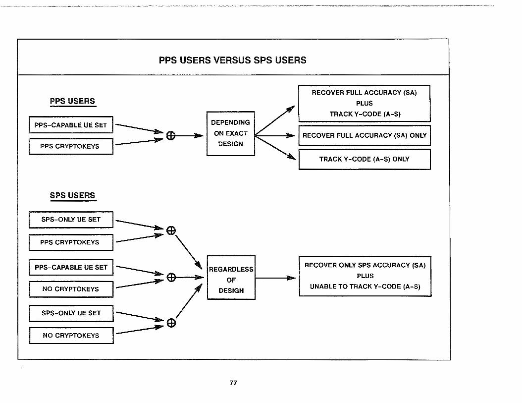
PPS USERS VERSUS SPS USERS
PPS USERS
PPS-CAPABLE UE SET 1------ . ---~~~~~~~ ~~EDI+--~•~
.___P_Ps_c_Rv_P_T_o_K_Ev_s _ _,1- ,.....
SPS USERS
SPS-ONLY UE SET I
DEPENDING
ON EXACT
DESIGN
------~~ED
PPS CRYPTOKEYS I- ,..... \ .------I PPS-CAPABLE UE SET I~ REGARDLESS
,..... ED ,.. OF
I NO CRYPTOKEvs I- I .___o_Es_i_G_N~
SPS-ONLY UE SET I~ EB
NO CRYPTOKEYS 1- Jill""'
77
-
RECOVER FULL ACCURACY (SA)
PLUS
TRACK Y-CODE (A-S)
RECOVER FULL ACCURACY (SA) ONLY
TRACK Y-CODE (A-S) ONLY
RECOVER ONLY SPS ACCURACY (SA)
PLUS
UNABLE TO TRACK Y-CODE (A-S)
4.9 SYSTEM INTEGRITY
There is still one other standard system operating condition assumption yet to be covered. It was present in all the foregoing discussions, but was not explicitly identified in the earlier list. It is so fundamental that it can be easily overlooked, but its importance will not allow it to be ignored once it is recognized. This is the special assumption of GPS system integrity. Its exceptions are vitally important to all GPS users.
If all of the previous standard assumptions about nominal operation of the OCS, Block II SV constellation, and PPS/SPS UE sets hold true, then the SIS and User Segment contributions to the UERE will combine in an rss-fashion to give a PPS UERE of 7.0 meters one sigma and an SPS UERE of about 32 meters one sigma. Knowing this, the user's current navigation accuracy (UNE, UHNE, and/or UVNE) can be computed by multiplying the appropriate UERE value by the appropriate current DOP value. Most UE sets perform this computation automatically for the user and provide a real-time output of their expected navigation accuracy. All the user thus needs to do is to simply monitor the expected accuracy output to determine whether GPS is accurate enough for safe navigation usage.
Exactly what constitutes "accurate enough for safe navigation" is completely dependent on the individual user's particular application. There are some established standards. For example, in the U.S. National Airspace System (NAS), horizontal accuracies of 1,000 meters 2 drms are defined as being good enough for safe en route aviation use.
System integrity comes into play when one asks just how reliable the expected navigation accuracy values provided by the UE set really are. Since UE sets always know which SVs they are using for their position solution process, there is no chance of any unreliability due to incorrect DOP values being used in the computations. Users are always alerted in real time to the fact they entered a DOP hole because the expected navigation accuracy values increase appropriately. There is, however, a slight risk the
78
actual SIS UERE contributions from some SV might not conform to the expected PPS or SPS UERE contribution. The resulting divergence between the actual and expected UEREs is the important exception to the assumption of GPS system integrity. It represents a condition wherein users may be relying on inaccurate PVT data from the UE set without being warned the PVT solution does not have enough accuracy to be safely used. Clearly, this is not an acceptable situation from the GPS user's point of view.
As a result of the risk these UERE divergences pose to system integrity, GPS development efforts have focused on preventing their occurrence. Potential failure modes within the Control and Space Segments have been identified and eliminated to the maximum extent possible. Where they could not be completely eliminated, built-in detection mechanisms were installed to catch off-nominal OCS and Block II SV performance before it has a chance to affect the SIS contribution to the UERE. The Block II SVs will actually switch themselves to transmitting untrackable nonstandard codes instead of the normal PRN codes within 1 O seconds of detecting a failure. For SIS UERE divergence problems which develop over a long period, the OCS provides forecast UERE values (called "user range accuracy" or URA) in the 50 Hz navigation messages sent to both PPS and SPS users. Most UE sets incorporate a range of built-in test (BIT) features to detect, isolate, and warn users about internal faults. Many vehicles are normally equipped with self-contained navigation sensors, such as an inertial system, which will help detect unexpected PVT accuracy degradations.
Even with so many built-in prevention/detection functions, a very small possibility remains that UERE divergences might sneak through to affect users without a timely warning. Estimates for the probability of such an event suggest it might be expected once every four months or so for a full-up constellation of 21 SVs and might last anywhere from 90 minutes to 4 hours. In response to this small but still significant risk, plans are being formulated for back-up safety nets which will continually monitor the SIS from each SV and guarantee a warning to the user in the event of a significant UERE divergence.

SYSTEM INTEGRITY
DEFINITION OF SYSTEM INTEGRITY:
"THE ABILITY OF THE SYSTEM TO PROVIDE TIMELY WARNING TO USERS WHEN IT SHOULD NOT BE USED FOR NAVIGATION."*
END USER UESET
DETERMINE SAFE LEVEL OF
REAL-TIME COMPUTATION NAVIGATION ACCURACY
AND OUTPUT OF CURRENT __ ___.> FOR PARTICULAR APPLICATION; < EXPECTED NAVIGATION MONITOR UE SET
ACCURACY --- OUTPUTS OF EXPECTED --
NAVIGATION ACCURACY • DOP VERSUS THE REQUIRED • UERE (URA)
NAVIGATION ACCURACY
7
SYSTEM INTEGRITY
79
APPLICATION
SPECIFIED STANDARDS
FOR REQUIRED NAVIGATION
ACCURACY
EXAMPLES FOR THE U.S.
NATIONAL AIRSPACE:*
• ENROUTE AVIATION
- 1000 m, 2 drms
• TERMINAL AVIATION
- 500 m, 2 drms
• NON-PRECISION
APPROACH
- 100 m, 2 drms
* FEDERAL RADIONAVIGATION PlAN,DECEMBER1990
5.0 USER SEGMENT DETAILED DISCUSSION
Section 3 gave a brief system-level overview of the three GPS segments and their interfaces. The User Segment description was necessarily short and consisted of little more than an identification of the major components and their purposes. Since this is the segment that will directly support you, the GPS user, it needs to be addressed with much greater detail than was possible in the system-level overview.
This section provides a detailed discussion of the various UE sets along with their HVIA, AME, and SE. However, to limit the scope, only the standard DoD UE sets and related components procured by the GPS JPO will be addressed. For details on UE set types not covered herein, refer to literature from the particular manufacturer and/or procuring agency.
5.1 UE SETS
Each UE set must perform a number of basic functions in order to derive PVT data from the SY-broadcast SIS. These basic functions give rise to a generic architecture shared by all UE sets. Even though there is a great deal of variability in the ways different UE sets actually implement these basic functions-and the range of optional features that may also be supported-the generic UE set architecture still remains the same.
This discussion of the standard DoD UE sets begins with the generic architecture of a UE set and the basic functions performed. Next, some common characteristics of the standard DoD UE sets are addressed. Finally, the 1 o standard DoD UE sets are described in tum; the various ways they implement their basic functions, the optional features they support, and the ways they differ in their operating characteristics.
80
5.1.1 Generic UE Set
5.1.1.1 Architecture
The generic architecture of a UE set consists of four main functional areas:
1. An L-band antenna
2. A spread spectrum GPS receiver
3. A data processor (plus software)
4. Some means to output the PVT results
The L-band antenna is a necessary part of every UE set to enable it to receive the SY-broadcast SIS.
A spread spectrum GPS (PM radio) receiver is required in order to track the PRN ranging codes, generate the PR measurements, and demodulate the SVs' 50 Hz navigation messages.
A data processor (plus appropriate software) is needed to handle the four-equation/four-unknown position solution process and to control GPS receiver operations. The data processor also must generate the PVT data for output in the desired format and support whatever optional features are designed into the particular UE set.
The PVT output (and external input provisions) are not really required from the UE set perspective, but are essential for the user to make use of the PVT data. If the user is an external on-board navigation suite, then a digital means of output will be required. If the user is a human operator (pilot, navigator, etc.), then the output will most likely be through a CDU.
The following paragraphs describe these four main functional areas in further detail and discuss how they interact with each other. A subsequent section covers how they operate together and interact with the user.

l-BAND ANTENNA
SPREAD SPECTRUM GPS RECEIVER
DATA PROCESSOR (PLUS SOFTWARE)
PVT OUTPUT MEANS
GENERIC ARCHITECTURE OF A UE SET
1 ,
• TRACK PRN RANGING CODES • GENERATE PR MEASUREMENTS • DEMODULATE 50 HZ NAV MESSAGES
• FOUR-EQUATION/FOUR-UNKNOWN SOLUTION PROCESS
• CONTROL GPS RECEIVER • GENERATE PVT DATA OUTPUT • SUPPORT OPTIONAL FEATURES
+ + I
' I L ___ _.
DIGITAL OUTPUT (AND INPUT)
81
HUMAN OPERATOR INTERFACE
CONTROL DISPLAY UNIT (CDU)
5.1.1.2 Generic L-Band Antennas
Simply stated, the primary function of a generic L-band antenna system is to receive the SY-broadcast SIS. This requires it to first pick up the PM radio waves that beam down from the onorbit SVs, convert them to an electrical signal, and then amplify and forward that electrical signal to the GPS receiver via a coaxial cable output. This is not as easy a task as it might seem.
The PM radio waves that make up the SY-broadcast SIS are very low-power L-band signals. (SIS power levels at the earth's surface are actually below that of the sky's normal background noise.) This makes their reception strictly line-of-sight. The SIS cannot be recovered inside a building nor under water. Even dense foliage overhead can interfere with the antenna's ability to pick up enough power and thereby prevent tracking the obscured SYs. Clouds and rain do not significantly affect the recovered signal power, but a layer of ice or snow covering the antenna certainly will. As a general rule, if you can see the portion of sky where an SY is, then a generic L-band antenna will be able to pick up adequate power from that SY.
Depending on the kind of GPS receiver used, the l-band antenna system must receive and forward different portions of the SY-broadcast SIS. If the GPS receiver is one that makes use of both the L 1 and l2 signals, the antenna must be capable of receiving both l-band frequencies and must have sufficient bandwidth to handle the ± 10.23 MHz-wide spread of the P- or Y-code signals (only the P- or Y-codes are normally present on l2). If the G PS receiver only uses the C /A-code on L 1, then the antenna only needs ± 1.023 MHz of bandwidth centered at just the l 1 frequency. All GPS L-band antennas are right-hand circularly polarized.
There are two different types of L-band antennas that can be used depending on whether jamming is an expected threat or not; fixed reception pattern antennas (FRPAs) and controlled reception pattern antennas (CRPAs). FRPAs have gain patterns that are permanently determined by the design of the receiving element in the antenna. As an example, typical hemispheric FRPAs use
82
receiving elements that give them a fairly uniform near-zero gain pattern everywhere in the hemisphere above the plane of the antenna except for very low angles near the antenna's horizon. Signals coming into the antenna from these low angles will not be picked up with enough power to be used (they are said to be "gain masked"). The most gain for a hemispheric FRPA is usually directly overhead.
CRPAs differ from FRPAs in that their gain patterns are controllable in real time. By using multiple reception elements as an adaptive array antenna, a null (gain drop out) can be created to blank out a portion of the nominal gain pattern and so thwart high-power jammer signals. CRPA systems include a specialized antenna electronics (AE) unit to create a null and then steer it in a pseudorandom fashion across the nominal gain pattern to minimize the total measured power in either the L 1 or l2 frequency band. This scheme results in the null being oriented directly towards the jammer because the jammer is a point source of RF energy operating at far higher power than the sky's background noise, and orienting the null in its direction reduces the AE's total received power. The SYs are also point sources of RF energy, but they are ignored by the AE since their power level is lower than the background noise. Most CRPA systems are capable of generating and steering multiple nulls so as to counteract the threat from multiple jammers. Although it is possible to have an l1-only CRPA, all standard DoD CRPA systems are switchable between nulling on either L 1 or l2. While null-steering CRPA systems do not offer as much anti-jamming protection as would a beam-steering antenna system (i.e., one that steers gain peaks in the direction of the SYs), they are far less expensive and much more reliable with current technology.
The last thing done by a generic L-band antenna system prior to outputting its electrical signal to the GPS receiver is to amplify the signal to account for expected cable losses. This amplification is generally required except when the antenna-to-receiver coaxial cable length is less than about two meters. As a result, almost all FRPA systems also include their own AE unit to perform the necessary preamplification.
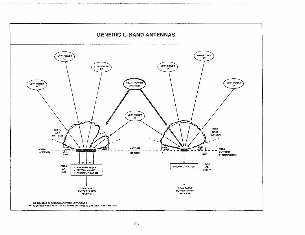
GENERIC l-BAND ANTENNAS
LOW-POWER sv•
CRPA ANTENNA
LOW-POWER sv
GAIN
CRPA AE
UNIT
• POWER MEASURE • PATTERN ADJUST • PREAllllPUFICATION
COAX CABLE OUTPUT TO GPS
RECEIVER
• ALL NAVSTAR SY SIGNALS ARE VERY LOW-POWER •• REQUIRED WHEN FRPA-TO-RECEIVER DISTANCE IS GREATER THAN 2 METERS
ANTENNA
HORIZON
83
--
PREAMPUFICATION
COAX CABLE OUTPUT TO GPS
RECEIVER
LOW-POWER sv
FRPA GAIN
PATTERN
- . GAIN
FRPA AE
UNIT ..
FRPA ANTENNA (HEMISPHERIC)

5.1. 1.3 Generic GPS Receiver
The three major functions of a generic GPS receiver are to acquire and track the SY-broadcast PRN ranging codes, measure the PR from each SY based on the received PRN ranging codes, and demodulate the 50 Hz navigation messages. The primary input used by the generic GPS receiver for these three functions is the electrical signal provided by the L-band antenna. The primary outputs of a generic GPS receiver are SY-specific PR measurements and the 50 Hz navigation messages provided to the data processor. There are also secondary inputs and outputs, some of which will be covered in the following discussions. To accomplish its three major functions, a generic GPS receiver will typically include:
• A down converter • A quartz clock/frequency synthesizer • One or more PM signal tracking channels
The down converter in a generic GPS receiver filters out extraneous signals and converts the RF inputs from the L-band antenna down to the particular internal intermediate frequency (IF) at which the GPS receiver's signal-tracking channels work. In an L 1 C/A-code receiver, the down converter will first filter out everything outside of a 1575.42 ± 1.023 MHz frequency band and then convert the remaining RF signal down to the internal IF. In an L 1 /L2 P (Y)-code receiver, the down converter first splits the incoming electrical signal in half. One half is filtered in an analogous fashion over a 1575.42 ± 10.23 MHz frequency band and down-converted to the IF while the other half is filtered over a 1227.6±10.23 MHz frequency band and downconverted to the same IF. Even though the two halves are down-converted to the same frequency, the separate L1 IF and L2 IF signals cannot be recombined. They will instead be accessed and used independently-but identically-by the PM signal-tracking channels. In certain UE set designs, the down converter will actually be physically located in the AE unit instead of in the GPS receiver
84
unit. You can usually tell which GPS receivers are designed to use an outboard down converter because there will be two coaxial cables running from the AE unit to the GPS receiver, one for the L 1 IF and one for the L2 IF.
The quartz clock/frequency synthesizer in a generic GPS receiver provides the internal master time pulse for generating PR measurements and is the source of all reference frequencies within the UE set. The quartz clock is basically a very low-noise crystal oscillator placed inside an oven to guard against frequency and time fluctuations caused by temperature changes. The oven is typically a vacuum bottle with electric heaters to keep the quartz crystal at a constant temperature near 100°C. In many ways, this ovenized quartz clock resembles a modern quartz wristwatch which also keeps good time because it is protected from temperature changes by being worn tight against the skin of the wrist. Although the quartz clock in a generic GPS receiver is not as accurate as the atomic clocks in the SYs, it is far less expensive and is adequate for the job. Because the reference frequencies are generated from the output of the quartz clock, they are extremely stable as well.
The PM signal-tracking channels in a generic GPS receiver use the internal master time pulse along with the reference frequencies from the quartz clock/frequency synthesizer to process the downconverted L 1 /L2 signals at IF. Each channel can track only one component of an SY's signal at a time. To simultaneously track all normal signal components from a particular SY would require three channels: one to track the C/A-code from the L1 IF, one to track the P(Y)-code from the l1 IF, and one to track the P(Y)-code from the L2 IF. There are usually one, two, or five channels in a GPS receiver, and all channels within a particular receiver are identical (i.e., all are C/A-only channels or all are channels with both C/A- and P-code capabilities). The channels operate independently under the control of the UE set's data processor, receiving their own individual signal-tracking orders as digital inputs from the data processor and providing their own digital outputs back to the data processor.

GENERIC GPS RECEIVER
-- - -. l CHANNEL1 - -- ..... .,,,
DOWN L1 IF .... -- ~
- - ... CONVERTER CHANNEL 2*
L2 IF ..... - - ..... (AND FILTER) ,.., - - -
) RF INPUT )lllla
j '
k .... - I CHANNEL 3• I ,... i.... DIGITAL -REFERENCE ..- - "" OUTPUT -
FREQUENCIES ~ .... - ..... DIGITAL - - INPUT
"" - -• 1 • FREQUENCY ,., - -
SYNTHESIZER CHANNEL 4* - - -. - -- .,;
QUARTZ MASTER TIME "-CLOCK PULSE
~ ~ - ::- · 1 r . CHANNEL 5* - -- - --
* 5-CHANNEL L 1 /L2 GPS RECEIVER SHOWN FOR ILLUSTRATION PURPOSES ONLY
85

The PM signal-tracking operations performed by a channel in a generic "analog-type" GPS receiver illustrate many of the principles that govern UE set operation (the channels in a "digitaltype" receiver operate in a similar, but slightly different manner). A generic analog channel starts operating when it receives a signal-tracking order from the UE set's data processor. This order tells the channel which PRN code to track and which IF input signal to use. It also provides the channel with an initial estimate (a guess) as to the PR from the SV and the Doppler shift on the IF signal. (How these estimates are generated will be covered in the section on generic data processors.)
An analog channel responds to the tracking order by performing the following sequence of steps. First, the channel connects its IF input line to the desired IF signal (not necessary in L1-only receivers). It then starts generating a copy of the desired PRN code (C/A or P) based on the master time pulse from the quartz clock. The channel next slews the generated replica PRN code forward or backward from the master time pulse; the distance slewed forward (advancing the code in time) or backward (retarding the code) will be exactly equal to the data processor's initial guess at the expected PR value multiplied by the speed of light. The data processor's initial guess at the expected Doppler shift is likewise used to set up a nominal slewing rate that continually advances or retards the code sequence. The acquisition finishes with the channel slewing its replica PRN code forward and backward in time while simultaneously adjusting the nominal slewing rate faster and slower until the replica PRN code exactly matches up with the desired PRN code in the IF signal. This matchup is called "correlation."
Once the channel is able to consistently maintain correlation between its replica PRN code and the incoming PRN code, it will notify the data processor it has achieved "code lock". It then starts outputting a value for the total amount of slewing required to maintain correlation between the PRN codes. This amount-ofslewing value is the channel's PR measurement (i.e., the time difference between the master time pulse and the incoming PRN code time). The UE set data processor will normally sample the PR measurements once per second.
86
After code lock is achieved, the data processor may also order the channel to begin demodulating the 50 Hz navigation message data added to the PRN code by the SV and to start outputting it for data processor use. If it is a P(Y)-code-capable GPS receiver and acquisition was on the C/A-code, the data processor may also order the channel to hand over to P(Y) operation. In addition to the outputting of 50 Hz navigation message data, a number of other optional outputs can be ordered by the data processor. Foremost amongst them are measurements relating to the power ratio between interfering signals (e.g., jammers) and the SV signals. This jammer-to-signal (J/S) ratio information is very important for a dual-frequency military GPS receiver operating in a high-jamming environment. It can be used by the data processor to decide whether the tracking should be on L 1 or L2, depending on which frequency has the lower jamming level, and it can be output to the user for appropriate action. A commercial GPS receiver may instead measure the ratio of the carrier power to the noise level.
If the J /S level is not too high, the data processor may send an additional order directing the channel to also begin phasetracking the down-converted L 1 or L2 carrier wave. This is made possible through the nature of the spread spectrum GPS waveform. Just as the L 1 and L2 carrier waves were spread out when the SV phase-modulated them with its PRN code, the tracking channel can despread the incoming signal by using its exactly correlating copy of the PRN code. This allows the channel to recover the original L 1 or L2 carrier wave (albeit down-converted to IF). Comparing the phase of the despread carrier wave against a nominal carrier wave is advantageous since the number of carrier cycles during the measurement interval (typically one second) can be precisely counted by the channel. Using this carrier phase-lock technique, a so-called "delta range" or DR value (approximately equal to the average Doppler shift over that interval) can be computed by the data processor to be used as a velocity-type measurement in addition to the distance-type PR measurement. Note this carrier phase-lock operation requires that code-lock be achieved before phase-lock can start. And if the J /S level gets too high, the tracking channel may lose phase-lock but can still continue in code-lock operation.

GENERIC RECEIVER CHANNEL OPERATION
MASTER TIME PULSE------------. REFERENCE FREQUENCIES
DATA PROCESSOR INITIAL ESTIMATE
REPLICA PAN CODE C A OR P PAN CODE GENERATOR
FASTER SLEW SLOWER ADJUSTOR
AMOUNT OF SLEWING
"PR MEASUREMENT"
INCOMING SIGNAL POWER MEASUREMENT
REPLICA CODE AHEAD/BEHIND
CORRELATION RRELATION DETECTED DETECTOR 1--.::.:..::.:.:.:.:..:=~=.:::.::~~::.:::..-~..,_
DESPREAD CARRIER AT IF
DESPREAD CARRIER SIGNAL POWER MEASUREMENT
50 HZ DATA BIT
DEMODULATOR
50 HZ NAVIGATION MESSAGE DATA
s
J
'------ DESPREAD CARRIER PHASE DETECTED ,..._- IF CARRIER 1-..;;.;;~~~.;:;.;.;;;,;,;.,;.,;.;;;.;.;..;...;.;.;.;;:;;;;;..;;;..::..:..::::.=-:..::.:;;--i•
PHASE COMPARE/
~ COUNTER
NOMINAL IF CARRIER WAVE
DIFFERENCE IN NUMBER OF CYCLES
NOMINAL IF GENERATOR
REFERENCE FREQUENCIES
87
"CODE LOCK"
"NAV DATA"
"J/S"
"PHASE LOCK"
"DR MEASUREMENT"

Now, let us consider how the PM signal-tracking operations performed by an individual channel in a 5-channel GPS receiver relate to operations performed by other channels in that receiver. Several UE set operating principles that apply in a generic sense to the 5-channel receiver also apply to the 1- and 2-channel receivers.
With five channels available, four of them can be dedicated to making PR and DR measurements continuously from four different SVs. This will satisfy the data processor's need for a fourequation/four-unknown position solution process. The choice of which SVs should be tracked is made by the data processor based on its own internal definition of what constitutes the best set of four SVs (see paragraph 4.6). The SY-tracking assignments on a per-channel basis can be made essentially at random by the data processor since all channels in a GPS receiver are identical. The choice of whether to track L1 C/A, L1 P(Y), or L2 P(Y) is made by the data processor based first on GPS receiver capabilities and second on jamming considerations. All things being equal, the preferred mode is L1 P(Y)-code. With continuous tracking of four SVs on four channels, the data processor can sample PR/DR measurements as often as needed (typically once per second).
The fifth channel is free to handle necessary "housekeeping" activities. One such housekeeping activity is making PR/DR measurements on the other frequency to support the dualfrequency ionospheric measurement model (only if the receiver has L 1 /L2 capabilities). A housekeeping activity unique to multichannel receivers is measuring the PR/DR from the same SV simultaneously on two channels to calibrate interchannel delays present in the receiver hardware. One of the most important housekeeping activities is the "advance planning" acquisition and tracking of SVs that are just rising at the UE set location. This is done in order to collect their subframe 1 /2/3 data and to check their health prior to validating them as candidates for use in a fourSV solution. If a channel should lose lock on one of the four best SVs because the SV is obscured by terrain or because the HV is rolling and banking, then having a prevalidated candidate SV can prevent UE set interruption.
88
A 1-channel GPS receiver cannot operate the same way a 5-channel receiver does. Most of the same functions must still be performed, but a single channel is not enough to allow continuous tracking on anything other than one SV. Normally, the data processor uses the single channel to perform sequential tracking. With the one-per-second operating rate, the channel will be ordered to sequence among the four best SVs, generating one PR/DR measurement pair per second and basically doing what the four main channels do in a 5-channel GPS receiver.
This presents a problem. With only one PR measurement at a time, if the UE set is moving, a four-equation/four-unknown position solution is impossible. With position and CB unknowns constantly changing from one second to the next, having only one PR measurement poses the impossible task of trying to solve for four unknowns using only one equation. Fortunately, there is a clever way for the data processor to work around this problem as long as the time span for the four measurements is not too long. (How a generic data processor does this is described in the next section.)
In addition to the sequential tracking of four SVs, the fifthchannel housekeeping activities must still be performed (except for the interchannel delay calibration). The data processor does this by periodically "stealing" tracking time. This lengthens the time span for a set of four sequential measurements. The worst-case condition occurs when the channel has to acquire a newly risen SV. Since the subframe 1 /2/3 data must be collected an entire subframe at a time, the requisite six-second dwell to collect a subframe of data will increase the time span required for four sequential PR/DR measurements to 1 O seconds.
One way to minimize the time span required for the four PR/DR measurements without incurring the cost of five channels is by using a 2-channel GPS receiver. This offers a reasonable compromise in many circumstances. The two channels can alternate between two SVs each when in a sequential four-SV tracking mode, and when required, one channel can handle the fifthchannel housekeeping activities while the other acts like a singlechannel GPS receiver.

5- vs 1-CHANNEL RECEIVER OPERATION
5-CHANNEL OPERJ.'TION
CHANNEL PAN #/OPERATION OVER TIME .... 7/A 7/A 7/A 7/A 7/A 7/A 7/A 7/A 7/A 7/A 7/A 7/A 7/A 7/A 7/A 7/A 7/A 7/A 7/A 12/A 12/A
2 20/A 20/A 20/A 20/A 20/A 20/A 20/A 20/A 20/A 20/A 20/A 20/A 20/A 20/A 20/A 20/A 20/A 20/A 20/A 20/A 20/A
3 4/A 4/A 4/A 4/A 4/A 4/A 4/A 4/A 4/A 4/A 4/A 4/A 4/A 4/A 4/A 4/A 4/A 4/A 4/A 4/A 4/A
4 19/A 19/A 19/A 19/A 19/A 19/A 19/A 19/A 19/A 19/A 19/A 19/A 19/A 19/A 19/A 19/A 19/A 19/A 19/A 19/A 19/A
5 7/B 20/B 4/B 19/B 7/A 20/A 4/A 19/A 7/B 12/C ,... 12/D 12/E 12/B 20/B
1-CHANNEL OPERATION
CHANNEL PAN #/OPERATION OVER TIME
7/A 20/A 4/A 19/A 7/B 20/B 4/B 19/B 7/A 12/C ---Jllo~ 12/D 12/E ----------11;::.i.- 20/A 4/A
CHANNEL OPERATION NOTES
Assume SV PAN #7, 20, 4, and 19 are visible and SV PAN #12 is rising.
A = L 1, P-Code, PR/DR
B = L2, P-Code, PR/DR
C = L1, CIA-Code, Acquisition
D = L 1, C/A-to-P, Hand over
E = L 1, P-Code, PR/DR and 50-Hz Navigation Message
89
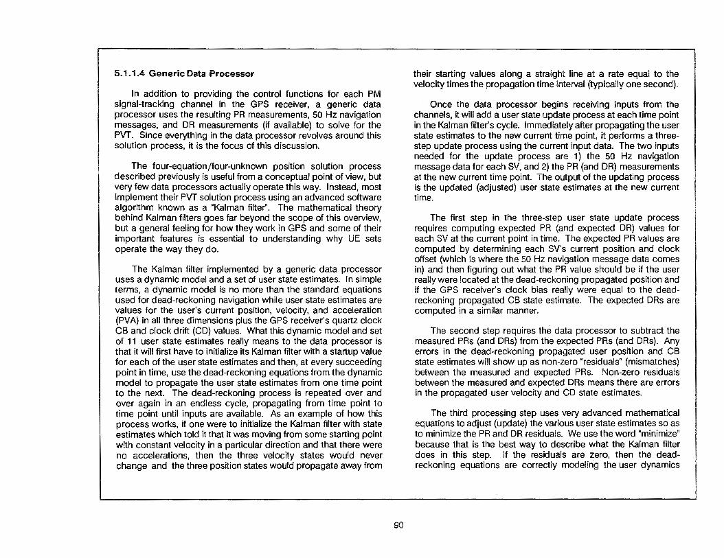
5.1.1.4 Generic Data Processor
In addition to providing the control functions for each PM signal-tracking channel in the GPS receiver, a generic data processor uses the resulting PR measurements, 50 Hz navigation messages, and DR measurements (if available) to solve for the PVT. Since everything in the data processor revolves around this solution process, it is the focus of this discussion.
The four-equation/four-unknown position solution process described previously is useful from a conceptual point of view, but very few data processors actually operate this way. Instead, most implement their PVT solution process using an advanced software algorithm known as a "Kalman filter". The mathematical theory behind Kalman filters goes far beyond the scope of this overview, but a general feeling for how they work in GPS and some of their important features is essential to understanding why UE sets operate the way they do.
The Kalman filter implemented by a generic data processor uses a dynamic model and a set of user state estimates. In simple terms, a dynamic model is no more than the standard equations used for dead-reckoning navigation while user state estimates are values for the user's current position, velocity, and acceleration (PVA) in all three dimensions plus the GPS receiver's quartz clock CB and clock drift (CD) values. What this dynamic model and set of 11 user state estimates really means to the data processor is that it will first have to initialize its Kalman filter with a startup value for each of the user state estimates and then, at every succeeding point in time, use the dead-reckoning equations from the dynamic model to propagate the user state estimates from one time point to the next. The dead-reckoning process is repeated over and over again in an endless cycle, propagating from time point to time point until inputs are available. As an example of how this process works, if one were to initialize the Kalman filter with state estimates which told it that it was moving from some starting point with constant velocity in a particular direction and that there were no accelerations, then the three velocity states would never change and the three position states would propagate away from
90
their starting values along a straight line at a rate equal to the velocity times the propagation time interval (typically one second).
Once the data processor begins receiving inputs from the channels, it will add a user state update process at each time point in the Kalman filter's cycle. Immediately after propagating the user state estimates to the new current time point, it performs a threestep update process using the current input data. The two inputs needed for the update process are 1) the 50 Hz navigation message data for each SV, and 2) the PR (and DR) measurements at the new current time point. The output of the updating process is the updated (adjusted) user state estimates at the new current time.
The first step in the three-step user state update process requires computing expected PR (and expected DR) values for each SV at the current point in time. The expected PR values are computed by determining each SV's current position and clock offset (which is where the 50 Hz navigation message data comes in) and then figuring out what the PR value should be if the user really were located at the dead-reckoning propagated position and if the GPS receiver's clock bias really were equal to the deadreckoning propagated CB state estimate. The expected DRs are computed in a similar manner.
The second step requires the data processor to subtract the measured PRs (and DRs) from the expected PRs (and DRs). Any errors in the dead-reckoning propagated user position and CB state estimates will show up as non-zero "residuals" (mismatches) between the measured and expected PRs. Non-zero residuals between the measured and expected DRs means there are errors in the propagated user velocity and CD state estimates.
The third processing step uses very advanced mathematical equations to adjust (update) the various user state estimates so as to minimize the PR and DR residuals. We use the word "minimize" because that is the best way to describe what the Kalman filter does in this step. If the residuals are zero, then the deadreckoning equations are correctly modeling the user dynamics

THE KALMAN FILTER IN THE DATA PROCESSOR
A. DEAD-RECKONING PROPAGATION
• ~ T0 +5 • I~ .~T0 +4 ATT0 ~ T0 +3
y • ~ Tc+2 • G.~T0 +1 To
INITIAL ZERO ACCELERATIONS POSITION AT To
x
TIME ]lllia To --. T0 +1 --. T0+2-. T0+3-. T0 +4-. T0 +5 POINT
POSITION n 4 8 12 16 20 24
STATES 10 12 14 16 18 20 0 0 0 0 0 0
n 4 4 4 4 4 4 VELOCITY
2 2 2 2 2 2 STATES
0 0 0 0 0 0
ACCELERATION n 0 0 0 0 0 0
STATES 0 0 0 0 0 0 0 0 0 0 0 0
CLOCK { CB 0 1 2 3 4 5 STATES CD 1 1 1 1 1 1
91
B. USER STATE UPDATE
INPUT INPUT 50 HZ NAVIGATION
MESSAGE DATA FOR EACH SV
INPUT PR (AND DR) MEASUREMENTS AT NEW CURRENT
TIME
PROPAGATE USER STATES
TO NEW CURRENT TIME
OUTPUT UPDATED (ADJUSTED) USER
STATES AT CURRENT TIME
COMPUTE EXPECTED PR (AND DR) VALUES
AT NEW CURRENT TIME
SUBTRACT MEASURED PRs (AND DRs) FROM EXPECTED PRs (AND
DRs) TO FIND "RESIDUALS"
ADJUST PROPAGATED USER STATES SO AS TO
"MINIMIZE" THE RESIDUALS
OUTPUT

and the minimizing process results in the updated state estimates that are identical to the propagated state estimates. If the residuals are non-zero, then the minimizing process will result in the best possible updated state estimates based on all available measurements.
By running the Kalman filter processes in a recursive algorithm (propagating-then-updating ad infinitum), a generic data processor can determine the user PVA plus CB and CD states far more accurately than it could by simply performing a pair of fourequation/four-unknown solutions (one solution with the PR measurements for user position and CB plus one solution with the DR measurements for user velocity and CD). The two beneficial characteristics of the Kalman filter algorithm which improve the state estimates so much are that it allows both noisy and/or partial sets of measurements to be used in the update process.
The PR and DR measurements from the GPS receiver's PM signal-tracking channels are normally subject to a fair amount of noise (random UERE) caused by the signal environment and by the channel hardware. Under jamming, this noise can grow quite large. The Kalman filter algorithm will automatically monitor the level of noise in the PR/DR measurement residuals and react by deweighting them when the noise level goes up and reweighting them more heavily when the noise level goes down. (The Kalman filter's actions in this regard are almost human because the filter judges how much to "believe" the measurements.) This characteristic allows it to respond to true mismatches between the measured and expected PRs and DRs caused by changes in the user states while ignoring false mismatches caused by channel noise. Thus, the effects of noise are essentially filtered out and not allowed to affect the state estimate update. By contrast, the fourequation/four-unknown solution process has no equivalent way of doing this type of filtering, and its results simply bounce around following the noise.
With a 1-channel GPS receiver, the set of PR and DR measurements available is limited to only one PR and one DR measurement at a time. This is not a sufficient number of measurements to even attempt a four-equation/four-unknown solution. Kalman filters are, however, able to make full use of all information avail-
92
able, even from partial measurement sets. By sequentially processing the PR/DR measurement pairs from each of four SVs as soon as they come in (one measurement pair per SV at each time point) and propagating the partially updated state estimates between the time points, a Kalman filter with a 1-channel GPS receiver is still able to achieve a better accuracy than would an equivalent four-equation/four-unknown solution as long as the time span for the four sequential measurement pairs is not too long.
The ability to operate with partial measurement sets obviously also applies to the Kalman filter with a 2-channel GPS receiver. Perhaps not so obvious is the application of this partial-measurement-set ability in a Kalman filter with a 5-channel GPS receiver. If one of the channels tracking the four SVs used in the solution loses lock for some reason, the ability to use a partial measurement set will allow the filter to carry on with minimal upset until an alternate SV can be acquired.
The Kalman filter's ability to use both noisy and partial measurement sets will provide excellent accuracy most of the time, but not always. The best accuracy will be achieved only so long as the real-world dynamics correspond with the assumptions of the dynamic model. The main problem occurs when the user's accelerations are not constant over the propagation interval as assumed by the dynamic model. (The term used to describe the changing user accelerations is "jerk".) When this happens, the dead-reckoning equations incorrectly propagate the state estimates, and the subsequent update process has to use a large fraction of the measurement information to estimate the changed acceleration states instead of using the available information primarily to refine the current position, velocity, and clock state estimates. As a general rule, the position accuracy degrades by a factor proportional to the jerk (acceleration change) divided by the total number of measurements available. Once the acceleration returns to a constant value, the accuracy will return to its normal level. Also note that even though the Kalman filter is capable of estimating acceleration states, their accuracy is quite poor compared to the position and velocity state accuracy. This is because the accelerations are inferred states whereas the positions and velocities are observed states.
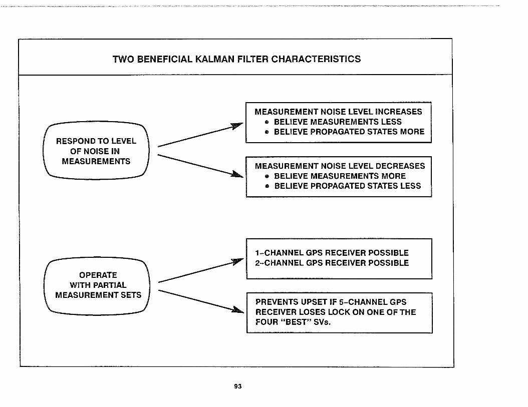
TWO BENEFICIAL KALMAN FILTER CHARACTERISTICS
RESPOND TO LEVEL OF NOISE IN
MEASUREMENTS
OPERATE WITH PARTIAL
MEASUREMENT SETS
93
MEASUREMENT NOISE LEVEL INCREASES • BELIEVE MEASUREMENTS LESS • BELIEVE PROPAGATED STATES MORE
MEASUREMENT NOISE LEVEL DECREASES • BELIEVE MEASUREMENTS MORE • BELIEVE PROPAGATED STATES LESS
1-CHANNEL GPS RECEIVER POSSIBLE 2-CHANNEL GPS RECEIVER POSSIBLE
PREVENTS UPSET IF 5-CHANNEL GPS RECEIVER LOSES LOCK ON ONE OF THE FOUR "BEST" SVs.

There are many benefits of a generic data processor's use of a Kalman filter, but those benefits do not come without certain drawbacks.
Kalman FilterTuning
One drawback of Kalman filters arises because they must be tuned to the real-world dynamics of the intended HV. With the range of HVs running from very-high-jerk platforms like jet fighter aircraft through medium-jerk platforms like helicopters to very-lowjerk platforms like a soldier's back, a truly generic "one-size-fits-all" Kalman filter is not possible. To get the best accuracy, HVs need to have slightly differently tuned Kalman filters. This is one reason why the GPS data processors are categorized by their built-in Kalman filter tuning design as high-dynamic (HD), mediumdynamic (MD), and low-dynamic (LD) units. As a general rule to minimize logistics costs, HD data processors are almost always paired with 5-channel GPS receivers, MD data processors with 2-channel GPS receivers. and LD data processors with 1-channel GPS receivers. There are significant exceptions to this rule, however.
Kalman Filter Initialization
A small logistics/maintenance drawback results from the requirement to start up the Kalman filter with initialization values for position, velocity, acceleration, and time (PVA& T) state estimates. The data processor supports this requirement by always keeping a certain part of its computer memory powered· up (called the "non-volatile memory" or NVM) and maintains its own ultra-lowpower clock (called the "low-power time source" or LPTS). Because of the need to supply power to its NVM and LPTS at all times, the data processor must use a keep-alive battery which requires periodic replacement. This periodic keep-alive battery replacement poses a small, but significant, logistics/maintenance burden since it is usually the only preventative maintenance required for most UE sets (required once every 6 months).
The data processor uses its NVM to save the most recent PVA state estimates each time it is turned off. It also calibrates its
94
LPTS against the GPS receiver's quartz clock while the UE set is operating and saves the LPTS bias and drift parameters in NVM. Thus, whenever the UE set is turned back on, the data processor can initialize the Kalman filter with the PVA& T values remembered from the last time it was used.
This automatic initialization feature works fine, except when the UE set has been moved a long way since it was turned off, or if maintenance has been performed and the keep-alive battery has been removed or replaced. To handle these circumstances, a generic data processor will always output its remembered PVA& T values to the user during start-up for verification and resetting. This minimizes the operational burden caused by the need to initialize the data processor. since resetting the remembered PVA& T values is only required if they are significantly different from the current/actual values.
Kalman Filter Performance Monitoring
Although not really an operational drawback per se, the use of Kalman filters means that data processors always have a PVT state estimate available for output. And since there is always an output available, it is difficult for the user to know whether the output is valid (based on a set of PR and DR measurements from four SVs) or invalid (based on either propagated state estimates or on an insufficient number of PR and DR measurements). Even if the PVT output is valid, the user will not know whether the DOP for the set of four SVs used was low and the solution is very accurate, or whether the DOP was high and the solution is not very accurate. Additional outputs from a generic data processor are therefore required to let the user know whether the PVT output is valid or not and, if valid, how accurate the output is. The three performance related outputs that the user should monitor are:
• A PVT valid/invalid warning flag
• A figure-of-merit (FOM) value in the range of 1 to 9
• Estimated UNE/UHNE/UVNE values
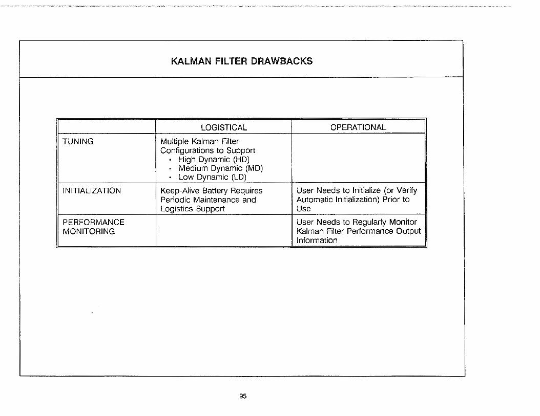
TUNING
INITIALIZATION
PERFORMANCE MONITORING
KALMAN FILTER DRAWBACKS
LOGISTICAL
Multiple Kalman Filter Configurations to Support
• High Dynamic (HD) • Medium Dynamic (MD) • Low Dynamic (LO)
Keep-Alive Battery Requires Periodic Maintenance and Logistics Support
95
OPERATIONAL
User Needs to Initialize (or Verify Automatic Initialization) Prior to Use
User Needs to Regularly Monitor Kalman Filter Performance Output Information

Many of the Kalman filter designs implemented in the data processors include an optional feature allowing them to process information from an external source as an additional input. Depending on the particular design, the external information that can be used includes: HV acceleration, velocity, and attitude measurements from an inertial measurement unit (IMU) or INS; velocity measurements from a Doppler radar velocity sensor (DRVS); altitude derived from a barometric (baro) altimeter or from knowledge that the UE set is operating at sea level; and precise time and/or frequency from an atomic clock. In manpack-type UE sets, the external information comes from the user in the form of: 1) an operator-entered altitude, 2) an operator-entered indication that the altitude is not changing (called "altitude-hold" mode), or 3) an operator-entered indication that the UE set is stationary (i.e., acceleration and velocity are zero).
The use of this feature is optional in the sense that external information is not required by the Kalman filter to generate its PVT solutions and most HVs without an external information source already installed do not need one added. This feature does, however, offer three major benefits which recommend it over the stand-alone mode of operation whenever a suitable source of external information is available for use.
When external acceleration or velocity information from an IMU/INS, DRVS, or operator input is available, it will be used for propagating the Kalman filter's state estimates from one time point to the next instead of the standard dead-reckoning equations from the internal dynamic model. Since IMU/INS or DRVS measurements are typically available at a much faster rate than the PR and DR measurements from the channels in the GPS receiver (20-50 Hz as opposed to 1 Hz), this enables the state estimate propagation between successive time points to be much more reliable and so avoids the jerk (non-constant acceleration) problem that degrades the data processor's output PVT accuracy when operating stand-alone in a high-dynamic environment. The operator-input stationary indication can likewise be used to improve the output PVT accuracy when the data processor operates in a survey mode. This Kalman filter benefit is known as
96
"dynamic aiding" of the PVT output. Dynamic aiding, in turn, also helps to improve the GPS receiver's resistance to jamming since the tracking channels can hold on to the signals much tighter without risk of losing lock due to unanticipated accelerations.
These external information sources all have very good shortterm stability but are subject to relatively large bias errors that can grow over the long term. For example, the accelerometers in an IMU can very accurately measure minute changes in the vehicle's accelerations but their ability to resolve the direction of those accelerations degrades over time due to the accumulated effect of gyro misalignments. On the other hand, the PR and DR measurements from the GPS receiver have a fairly high level of short-term noise (especially under jamming), but are extremely accurate and stable over the long term. The complementary nature of the two information types allows the Kalman filter to calibrate the long-term bias error in the external information source being used and also allows better filtering of the short-term noise in the PR and DR measurements from the GPS receiver. This is the benefit known as "external error calibration." A significant operational benefit also accrues for the user when the data processor outputs its calibration of the bias errors in the external information source, since this output will enable the user to correct or reset the external source.
The third major benefit of using external information comes into play whenever the GPS receiver loses track on one of the four SV signals and is unable to produce the PR and DR measurements needed for a solution. Because of the external error calibration benefit just discussed, the Kalman filter is able to compensate for the biases in the external source (strictly true only in the case of altitude or time/frequency) and then use the external measurements in lieu of one pair of PR and DR measurements in its state estimate update process. This has the effect of keeping the user state estimates very accurate even though the three-SV solution is technically invalid. This Kalman filter benefit is known as "coasting" on the external source.

OPERATING WITH EXTERNAL INFORMATION SOURCES
EXTERNAL INFORMATION
SOURCE
IMU/INS
DRVS
BARO/MSL
OPERATOR
ATOMIC CLOCK .,,
USER STATE INPUT TYPE
ACCELERATION
VELOCITY
POSITION (ALTITUDE)
PRECISE TIME AND/OR
FREQUENCY
*Will also improve the GPS receiver's resistance to jamming
97
KALMAN FILTER BENEFITS
DYNAMIC AIDING*
EXTERNAL ERROR CALIBRATION
COASTING

In addition to running its Kalman filter, a generic data processor must also perform several other critical functions. Among these are converting the external source information for internal use, controlling the GPS receiver PM signal-tracking channels, formatting and outputting the PVT solution, and performing BIT. Controlling the GPS receiver channels is the most critical because of its overall importance to UE set operation. The data processor provides this control automatically, both at start-up and periodically during normal operation, by performing the following steps.
1. At start-up, the data processor reads the LPTS to get current data and time. It also reads the NVM to get the most recent PVA state estimates, LPTS bias and drift terms, and the SV almanac data saved from when the UE set was last turned off.
2. Next, it outputs the remembered PVA&T values to be used for initialization and waits for the user to verify or reset them.
3. After user verification or entry of new initialization values, it uses the resulting coarse position and time in conjunction with information from the SV almanac data to determine the approximate position of visible SVs in the sky overhead. It then eliminates all SVs flagged in the almanac data as unhealthy and those below the minimum elevation mask angle from the list of visible candidate SVs.
4. Next, it examines all possible combinations of four SVs from the candidate list to find the best combination. (Different data processors use different "best" definitions depending on their application.) For the selected SVs, it generates expected PR/DR values using the initialization PVA&T along with the SV's almanac data.
5. The data processor then generates and sends tracking orders to the channels, directing them to track the selected SVs. If it is a 1-channel GPS receiver, the tracking orders
98
will be sent one at a time and the data processor will wait until the channel acquires the SV and returns the desired data before sending the next order. In a 5-channel GPS receiver, the data processor will send the tracking orders in parallel. 2-channel GPS receivers operate between these two extremes. Along with the tracking orders, the data processor also sends the channel an estimate of the PR and DR expected from the SV (the DR is scaled to the Doppler on the IF signal) to aid in signal acquisition.
6. After the data processor gets the desired data back from the channels, it uses its Kalman filter to solve for PVA&T. It then formats the PVT results for output to the user. Along with the PVT output, it also generates and outputs the necessary performance monitor data to inform the user about the quality of the PVT output. In a normal four-SV tracking mode, these computations will typically be repeated once every second. Every few minutes, the data processor will also repeat steps 3 through 5 to account for SVs rising and setting as well as the changing SV-to-user geometry and DOP.
Fifth-channel housekeeping activities are conducted as needed to collect fresh subframe 1 /2/3 data from 50 Hz navigation messages whenever the data changes or a new SV has risen, to make PR/DR measurements on the non-prime frequency for use in the dual-frequency ionospheric measurement model (if possible), and to collect new SV almanac data to save in the NVM. This slightly degrades the accuracy from 1- and 2-channel GPS receivers, but has no effect on 5-channel GPS receivers. (Handling these activities is the purpose of the fifth channel.)
Note that the expected PR and DR part of step 6 continues on a routine once-per-second basis to help the channel maintain tracking in case high jamming levels or dynamics are suddenly encountered. {This is known as "receiver aiding" and is very effective.) The expected PR and DR values used for receiver aiding are no more than the Kalman filter's own expected PRs and DRs computed as part of the update process.
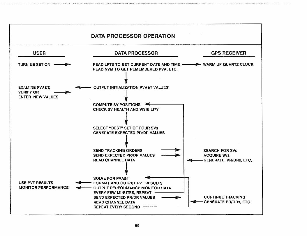
DATA PROCESSOR OPERATION
USER DATA PROCESSOR GPS RECEIVER
TURN UE SET ON .... READ LPTS TO GET CURRENT DATE AND TIME .... WARM UP QUARTZ CLOCK READ NVM TO GET REMEMBERED PVA, ETC •
• EXAMINE PVA&T; .. OUTPUT INITIALIZATION PVA&T VALUES VERIFY OR ....
• ENTER NEW VALUES
---COMPUTE SV POSITIONS ~
CHECK SV HEALTH AND VISIBILITY
+ SELECT "BESr' SET OF FOUR SVs GENERATE EXPECTED PR/DR VALUES
+ SEND TRACKING ORDERS .... SEARCH FOR SVs SEND EXPECTED PR/DR VALUES .... ACQUIRE SVs READ CHANNEL DATA .... GENERATE PR/DRs, ETC.
+ ~
SOLVE FOR PVA&T USE PVT RESULTS .. FORMAT AND OUTPUT PVT RESULTS MONITOR PERFORMANCE .. OUTPUT PERFORMANCE MONITOR DATA
EVERY FEW MINUTES, REPEAT SEND EXPECTED PR/DR VALUES .... CONTINUE TRACKING READ CHANNEL DATA .. GENERATE PR/DRs, ETC. REPEAT EVERY SECOND
99

5.1.1.4 Generic Output (and Input) Means
All UE sets must have some means to output their PVT information to the end user. Most UE sets also support one or more optional features, such as operating with an external information source or performing navigation functions, which require that they provide for both input and output of information. Generically speaking, the output/input means provided by each UE set-as well as the information flow back and forth across them-are known as its "user interfaces". There are many different types of user interfaces available, and UE set designs often incorporate several of them in parallel.
The specific user interfaces built into each UE set are intended to satisfy a broad range of user needs while minimizing costly oneof-a-kind customization. For some users, all that is needed is a simple digital output to supply the PVT solution results to a navigation computer. Other users require a user-friendly output/input device (a CDU) to interface directly with the human operator (driver, pilot, navigator, etc.). And still others need an interactive digital link (both output and input) between their onboard HV navigation suite and the UE set to enable the primary navigation system computer to directly control UE set operation and utilize the full range of its capabilities (such as its ability to calibrate an external information source). This wide range of user needs would be unmanageable if not for the adoption of standardized user interfaces.
For digital output and input, the UE set standardized user interfaces are designed to be compatible with a wide range of common military and commercial interface characteristics while supporting the unique capabilities of the UE set. As a representative example, most UE sets designed for aircraft installation will implement a configurable (A or B version) MIL-STD-1553 data bus that allows the HV to set up bi-directional communications
100
between the UE set and any other remote terminal on that bus. This digital user interface is able to handle all the interactive message traffic required for operation of the UE set, including but not limited to:
• Output of automatic PVA& T initialization data for user display and input of verification status or new data.
• Output of PVT results for user display or other HV use.
• Output of performance monitoring data for user display or HV use.
• Input of external source information for Kalman filter dynamic aiding, external error calibration, and coasting, along with output of external source calibration data for HV correction or reset of the external source.
• If a PPS-capable UE set, input of PPS keys and output of PPS status information for user display or HV use.
• If <l MILSPEC UE set, output measured J/S power ratio for user display or HV use.
• Output of BIT results along with other UE set status.
The standardized user interfaces are documented in a series of ICDs that describe the particular characteristics of each interface along with the message traffic they support. For interface characteristics and specific message traffic not supported by one of the existing standardized user interfaces, the use of HVIA will be required (an example of which is discussed in paragraph 5.2). Because of the complexity of these standardized user interfaces, an engineering design effort known as an "integration study" will normally be required to develop the HV-specific concept for exploiting UE set capabilities and to plan out the HV modifications necessary to install the UE set.
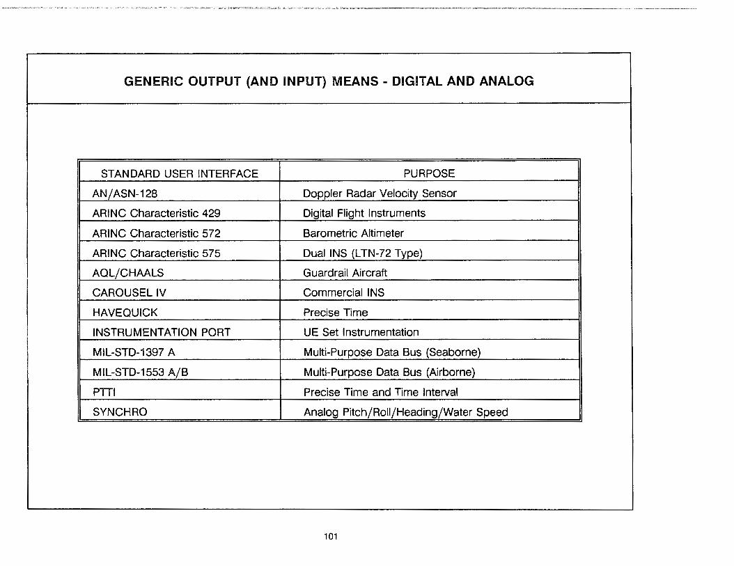
GENERIC OUTPUT (AND INPUT) MEANS - DIGITAL AND ANALOG
STANDARD USER INTERFACE PURPOSE
AN/ASN-128 Doppler Radar Velocity Sensor
ARINC Characteristic 429 Digital Flight Instruments
ARINC Characteristic 572 Barometric Altimeter
ARINC Characteristic 575 Dual INS (LTN-72 Type)
AQL/CHAALS Guardrail Aircraft
CAROUSEL IV Commercial INS
HAVE QUICK Precise Time
INSTRUMENTATION PORT UE Set Instrumentation
MIL-STD-1397 A Multi-Purpose Data Bus (Seaborne)
MIL-STD-1553 A/B Multi-Purpose Data Bus (Airborne)
PTT! Precise Time and Time Interval
SYNCH RO Analog Pitch/Roll/Heading/Water Speed
101

UE sets provide their direct user interface to/from a human operator by way of a CDU. Depending on the particular UE set, the CDU may be used instead of the standardized digital interfaces or it may be used in conjunction with those interfaces to provide an alternate path for information flow. Generic CDUs may be implemented as an integral part of the UE set, as a detachable hand-held component, or as an entirely separate LRU. Some important features of nearly all UE set CDUs are:
• A switch to control the UE set operating modes (OFF, INIT, NAV, and TEST are the generic modes).
• Automatic display of PVA&T initialization data followed by a prompt to the user for verification or input of new data.
• Operator-selectable coordinate system, map datum, and units for display of PVT data. (Despite GPS's common grid, many users employ other coordinate systems and use maps with different Earth references; this feature allows the user to tailor the output to be consistent.)
• Display of PVT results in the as-selected format.
• Display of performance monitoring information as a PVT valid/invalid warning, a FOM value in the range of 1 to 9, and set of expected accuracy values (UNE/UHNE/UVNE).
• Provisions for operator input of external information (altitude value, altitude-hold mode indication, or stationary indication) for Kalman filter dynamic aiding, external error calibration, and coasting.
• If a PPS-capable UE set, provisions for operator input of PPS keys and display of PPS status information.
• Display of measured J/S power ratio (MILSPEC equipment) or carrier-to-noise power ratio (NOi equipment)
• Output of BIT results
102
A very important feature of nearly all CDUs, and certain digital user interfaces, is the ability to accept the input of a "waypoint" (i.e., coordinates of some defined point in space) and then to respond back with UE-generated steering information relative to that waypoint. This is where the navigation application for UE set positioning comes into play.
The waypoints for a generic CDU are usually defined along with an associated mnemonic identifier (i.e., a name) and a desired track angle (DTK) in addition to their coordinates. The mnemonic name is used to facilitate operator selection of the correct waypoint from among those stored in memory (data for over 200 waypoints can be stored and accessed with most CDUs). The DTK is used to define the desired direction for approach to (or departure from) the waypoint. Depending on the particular UE set, moving waypoints may be supported as well as waypoints defined by range (RNG) and bearing (BRG) from the present UE set position, waypoints with an associated vertical glide slope, and waypoints with an automatic DTK based on the previous/next waypoints (TO-TO navigation).
Once the operator initiates waypoint-based navigation by selecting a waypoint mnemonic and deciding whether "TO" or "FROM" steering is needed, a generic CDU will respond with regularly updated displays of:
• RNG and BRG to/from the waypoint based on the great circle distance from present position and the operatorselected north reference (true or magnetic).
• Ground speed (GS) and time-to-go (TTG) relative to the waypoint.
• Course deviation information with respect to the desired track, either as a cross-track distance (XTK) or as an angular track error (TKE).

INTEGRAL:
HAND-HELD:
PANEL-MOUNTED
GENERIC OUTPUT (AND INPUT) MEANS - CDUS
NAVIGATION OUTPUT AND INPUT
I
.......... XTK
103
I FROM/;'
TO!f-/
I I
RNG/
/
/
DESIRED TRACK TO/FROM WAYPOINT
N
5. 1.2 Generic Operation and Maintenance Characteristics
5.1.2.1 Startup and Normal Operations
GPS UE sets are designed with operational simplicity in mind. For the generic UE set with a CDU only, a short sequence of actions by the operator is needed to bring the equipment up to its normal operating mode. In UE sets where there is no CDU and all user interaction occurs by way of the standardized digital interfaces, additional HY-unique startup steps may be required. In either case, once normal operation begins, the UE set will function autonomously and require little other than periodic checks to ensure its continued nominal performance. A typical sequence of operator actions for starting up a generic UE set with a CDU is as follows:
1. The operator first turns the CDU mode control switch from OFF to INIT (initialize), which energizes the UE set electronics. The data processor will use its internal LPTS to automatically set the date and time. The SV almanac data saved in NVM will be accessed, as will the remembered PVA from the last time the UE set was turned off. The ovenized quartz clock, which provides the UE set's internal master time pulse, will also start warming up. (Depending on the start temperature, it takes anywhere from 2 to 5 minutes for this oven to reach its normal operating point for UE sets without an "instant on" feature.)
2. While in the INIT mode, the automatic initialization PVA&T data will be displayed and the operator will be prompted to verify or reset them as necessary. The UE set also performs a short (less than 3-minute) self test to detect most faults and to warn the operator if the internal keep-alive battery is low. The operator can select the coordinate system, map datum, or units used for output at this time. Likewise, if it is a PPS-capable UE set and the operator has PPS keys, then this is the time to insert them into the UE set.
104
3. After the initialization process is complete, the operator will be prompted to turn the CDU mode control switch from INIT to NAV (navigate). With most CDUs, the operator will then have an option to select a display that shows the UE set's SV signal acquisition status. After some time (typically 2.0 to 5.0 minutes) the CDU will begin displaying PVT results with full accuracy. The 2.0 to 5.0 minutes between the switch from !NIT to NAV and the first fullaccuracy PVT output derived from four SVs is defined as the UE set's ''Time To First Fix" (TTFF). The total elapsed time between the switch from OFF to INIT and the first fullaccuracy PVT output is defined as the "reaction" (REAC) time. The difference between these two times is the additional 3 to 5 minutes allocated to REAC for operator initialization and warm up of the quartz dock's oven prior to the switch from INIT to NAV. Each UE set has its own individual TIFF and REAC characteristics.
4. Once the UE set is in the normal NAV mode, the operator can view the desired PVT results and, by entering the coordinates for a waypoint, obtain navigation information relative to that waypoint. During NAV mode operations, the operator should also check the PVT (navigation) valid/ invalid warning flag, the FOM, and the expected accuracy values on a periodic basis. If the performance monitoring data indicates unanticipated poor performance, the operator may wish to verify the antenna is properly cabled and that the antenna has an unobstructed view of the sky. (Particularly in the man-portable UE sets, SV signal obstructions from buildings and/or the operator's body often cause problems.) If the poor performance persists, selecting the CDU status display that shows the received J/S ratio may indicate the problem is due to high jamming levels. If so, then shading the UE set from the jammer by moving behind a hill or to a position farther away should cure the SV tracking problem.
5. If all else fails, turning the CDU mode switch to TEST will run the BIT diagnostics to identify the cause of the problem.

r--
L----
MODES
OFF
INIT
I I I I
~
GENERIC UE SET OPERATING MODES
STARTUP AND NORMAL OPERATOR ACTIONS
• Turn Mode Control Switch from OFF to INIT
• Verify or Reset Initialization PVA& T • If Desired, Select Coordinate System, etc. • If Appropriate, Insert PPS Keys • Turn Mode Control Switch from INIT to NAV
• If Desired, Monitor SV Signal Acquisition
• View PVT Results • Optionally, Enter Waypoint Coordinates and
Obtain Navigation Information • Check Performance Monitor Data • Turn Mode Control Switch OFF When Done
• Turn Mode Control Switch from NAV to Test in order to Run BIT to Diagnose Faults
• Turn Mode Control Switch back to NAV
105

5.1.2.2 Other Startup Characteristics
The normal startup sequence just described is known as a "normal start". It requires three conditions: the LPTS has been kept running since the last time the UE set was operated; the NVM contains a reasonably recent copy of the SV almanacs; and the UE set has a good estimate of the current PVA. For a normal start, the LPTS must be within 20 seconds or so of GPS time, the reasonably recent copy of the SV almanacs must be one obtained from the on-orbit SVs anytime within the last few weeks, and the "good" estimate of current PVA is defined as being within 100 kilometers for position and within 25 meters/sec for velocity. Under these conditions, the UE set's REAC time will usually be in the 7.0 to 10.5 minute range while the TIFF will be in the 2.0 to 5.5 minute range.
One special condition with regard to the normal start REAC and TIFF times needs to be mentioned. For PPS UE sets that use a Group Unique Variable (GUV) PPS key, the normal REAC and TIFF times will apply, but only with regard to an SPS accuracy for the PVT output. The full PPS accuracy takes an additional period of time to be realized. The reason for this delay is the GUV PPS
· key requires certain information from the SV 50 Hz navigation messages in order to become activated. This information is not used by UE sets operating in an SPS mode nor is it required by PPS UE sets operating with the other type of PPS key (the "weekly key" or CVw). With the GUV PPS key, the UE sets will first achieve an SPS level of accuracy, then seamlessly transition to fullaccuracy PPS operation once they acquire the appropriate information to activate their GUV keys from the SY-broadcast 50 Hz navigation messages.
A "cold start" occurs whenever there is a problem with the date and time from the LPTS or the SV almanacs in the NVM. This often occurs when the internal keep-alive battery has been removed for some reason. Under these conditions, the UE set has no way to determine which SVs are currently visible in the sky
106
overhead. When this happens, the UE set must enter a cold start acquisition process, randomly trying to acquire an SV's C/A-code signal to set its date/time and retrieve a current copy of the SV almanacs. Once the new set of SV almanacs is collected, the UE set can then switch over to completing a normal TIFF sequence. The net effect of performing a cold start is to delay the REAC and TIFF times by about 15 minutes.
Certain UE sets are able to take advantage of an optional set of startup conditions that result in short REAC and TIFF times. This is known as a "hot start". A hot start requires that the UE set have: a very accurate input of GPS time from an external clock (on the order of a few microseconds); recent subframe 1 /2/3 data for each SV to be tracked (normally input from an external source); and very good PVA data for initialization (1 O kilometers for position and negligible errors for velocity). Under these conditions, the UE sets will be able to acquire the P-code directly and can decrease the REAC and TIFF times to the bare minimums. Because of the special conditions needed, these times are designated as REAC-2 and TIFF-2, and are on the order of 4.5 minutes and 0.5 minutes respectively. This UE hot start capability is most often used on submarines, which already have external atomic clocks on board and need to minimize the above-surface exposure time of the UE set antenna.
"Hot restarts" occur under a special set of conditions supported by certain battery-powered UE sets. To save battery life, these UE sets implement a STANDBY feature that turns off all internal functions except for the ovenized precision clock and the main data processor memory. When the operator switches the UE set from NAV to STANDBY, the ovenized quartz clock continues to maintain GPS time and the current subframe 1 /2/3 data for each SV is stored in main UE set memory. When switched back from STANDBY to NAV, the hot restart capabilities allow the UE set to rapidly reacquire the SV signals and generate a new PVT fix. The elapsed time between the switch from STANDBY to NAVand the next full accuracy fix is known as "Time to Subsequent Fix" (ITSF) and is on the order of 10 seconds.

GENERIC UE SET STARTUP CONDITIONS
PVT AVAILABLE: STANDBY
FIRST FULL- INTERRUPTION FIX ACCURACY
'---- ___ _/ v
"----v REAC
NORMAL START
TTFF ~
• Normal Condition, Nominal REAC and TIFF Times • LPTS is OK, Current SV Almanacs in NVM, Good PVA for INIT
COLD START
• Abnormal Condition, Very Long REAC and TIFF Times • LPTS is Out, No SV Almanacs in NVM, Good PVA for INIT
HOT START
• Optional Condition, Very Short REAC and TIFF times • External Clock Instead of LPTS, Recent Subframes 1/2/3, Very Good PVA
HOT RESTART
• Condition After "STANDBY'' Interruptions, Very Short TTSF
y
TTSF
• Internal Ovenized Quartz Clock Instead of LPTS, Current Subframes 1/2/3, Very Good PVA
107
TIME

5.1.2.3 Reliability and Maintenance Characteristics
The MILSPEC requirements for UE set reliability and maintainability were established to emphasize high reliability and ease of maintenance. The reliability requirements for generic types of MILSPEC UE sets are defined in terms of the mean time between failure (MTBF) values provided on the accompanying table. The maintainability values for mean corrective maintenance time (Mer) and maximum corrective maintenance time (Mm CT) are also listed on the table. Most NOi UE sets have no form~requirements for reliability or maintainability other than a goal of ''very reliable". The NOi manpack MTBF value on the accompanying table is based on manufacturer-supplied data and is provided for reference only.
Generic UE sets (both MILSPEC and NOi) incorporate on-line performance monitoring features that provide an indication of operational readiness, warn of degraded performance, and facilitate maintenance actions. The on-line self-test capabilities of MILSPEC UE sets will indicate equipment malfunctions for at least 90 percent of all failure modes. For malfunctions indicated by the self-test capabilities, the false alarm rate will not exceed 5 percent.
LAU fault isolation using the MILSPEC UE set off-line BIT features may be initiated either by the operator or by maintenance personnel. Operator-initiated test results will be saved by the UE set in NVM for later review by maintenance personnel.
5. 1.2.4 Maintenance Support Concept
Each of the U.S. military services established organic maintenance concepts for the MILSPEC UE sets. These concepts include two or three levels of maintenance, depending on the service and particular HV. Initial organic maintenance by the services is scheduled to start in October 1992, when the contractor support provided by Rockwell-Collins under the terms of a performance reliability warranty (PAW) will end.
The Army maintenance concept for manpack and ground vehicle UE sets includes three levels of maintenance: unit, inter-
108
mediate (forward and rear), and depot. Unit-level personnel will identify failed LRUs through the use of the TEST-mode BIT features. The UE set will be repaired by removal/replacement of the faulty LRU. The faulty LRU will then be sent to an Intermediate (forward) facility, which will use an Intermediate Test Set (ITS) to isolate to the faulty shop replaceable unit (SRU).
The LAU is repaired by removal and replacement of the failed SRU, and the SRU is then sent to the intermediate (rear) level for repair. The intermediate (rear) level diagnoses selected faulty SRUs through the use of automatic test equipment (ATE). Repair actions that cannot be accomplished at the lower levels will be performed at the depot level. The ITS and ATE are SE items discussed further in paragraph 5.4.
The Army maintenance concept for airborne UE sets also consists of three levels: Aviation unit maintenance (AVUM), aviation intermediate maintenance (AVIM), and depot. The maintenance concept for these three levels is the same as the three levels for manpack and ground vehicle UE sets.
Most Air Force and Navy aircraft also employ a three-level maintenance concept. At the organizational (unit) level, the faulty LRUs are replaced based on BIT indications and repaired at the intermediate level by SRU replacement. Failed SRUs at the intermediate level are then sent to the depot for repair.
Navy shipboard UE sets follow a two-level maintenance concept whereby failed SRUs are identified using off-line built-in test equipment (BITE) contained within those UE sets (no ITS is required) and are replaced from the ship's stores. The failed SRUs are then sent to the depot for repair.
The maintenance concept for the NOi UE sets has so far consisted solely of returning the failed equipment to the manufacturer for repair or replacement. No organic support is currently envisioned by any of the military services for the NOi UE sets. This is subject to change in the future, however.

UE SET RELIABILITY AND MAINTAINABILITY
Reliability Maintainability
Mature Organizational Level Intermediate Level MTBF
McT MmaxCT McT MmaxCT (hr) (hr) (hr) (hr) (hr)
MILSPEC 2,000 0.25 0.33 0.75 1.50 Manpack
MILSPEC UE set for 929 0.25 0.33 0.75 1.50 Helicopters
MILSPEC UE set for 1,000 0.33 0.50 1.00 2.00 Fighter Aircraft
MILSPEC UE set for 680 1.50 N/A 1.50 N/A Ships and Submarines
NDI Manpack >15,000 N/A N/A N/A N/A
109

5.1.3 The Various UE Sets
There is already a wide variety of UE set types in the DoD inventory and the number will undoubtably continue to grow as new applications are developed. This section covers only the specific UE sets now available or available soon through the GPS JPO. The accompanying table summarizes these UE sets. For information on other types of UE sets, you should either refer to the manufacturer's literature or contact the developing organization. For example, to find information on UE sets designed for test range applications, one would contact the Range Applications Joint Program Office (RAJPO) located at the U.S. Air Force's Munitions Systems Division (MSD) at Eglin AFB, FL
The JPO-procured UE sets all have their GPS receiver and data processor functions combined into one LRU. Because of this architectural design, the various UE set types addressed herein are identified by the name of the LRU that forms the central element of each UE set. This LRU is often referred to as the receiver/ processor unit (RPU) or simply as the receiver (RCVR). We will use RCVR in this section. There is also a U.S. military nomenclature for most of the MILSPEC UE set configurations; the military nomenclature is given in the accompanying table along with the common RCVR name.
Unless otherwise specified, all of the UE set components described herein should be assumed fully qualified for use in their intended operational environments. For airborne UE set LR Us, this means compliance with MIL-E-5400R. For seaborne and groundborne LRUs, the compliance specifications are MIL-E-16400G and MIL-E-4158 respectively. When UE set LRUs such as the standard
110
CDU (STD CDU) or certain antenna and AE units are identified as being used In both air and sea, sea and ground, or air and ground applications, the component should be assumed as qualified for the worst-case environmental conditions.
The dimensions for the airborne RCVR LRUs are commonly referred to in terms of a fractional ATR unit. The use of this fractional ATR sizing is fairly common in both military and commercial avionics. Within the military, "ATR" is taken as the acronym for Air Transport Racking per DoD-STD-1788. Within commercial aviation, "ATR" has been standardized as the acronym for Austin Trimble Radio per ARING Characteristic 404A. Regardless of the acronym sources, a ·1 ATR long" unit has a height of 7.62 inches, a width of 10.12 inches, and a length of 19.52 inches. A "1 ATR short" unit has the same height and width as the 1 ATR long unit, but is exactly 7 inches shorter in length. The long and short length dimensions are the same for all fractional ATR units, as are the height dimensions. The only dimension that changes with the fractional unit sizes is the width. A 3/4 ATR long unit has height-width-length (HWL) dimensions of 7.62 inches by 7.50 inches by 19.52 inches while a 3/8 ATR short unit has HWL dimensions of 7.62 inches by 3.56 inches by 12.52 inches.
The airborne MILSPEC RCVRs all include a "doghouse" (as defined by ARINC Characteristic 404A) on the front of the unit. The doghouse, which extends approximately 2.5 inches beyond the ATR lengths given above, contains the keep-alive batteries for the NVM/LPTS, a time totalizing meter, and a handle to enable removal and installation of the RCVR unit. Having the keep-alive batteries in this location facilitates their once-every-six-month replacement.
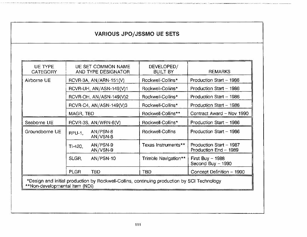
UE TYPE CATEGORY
Airborne UE
I Seaborne U E
Groundborne UE
VARIOUS JPO/JSSMO UE SETS
UE SET COMMON NAME DEVELOPED/ AND TYPE DESIGNATOR BUILT BY
RCVR-3A, AN/ ARN-151 (V) Rockwell-Collins*
RCVR-UH, AN/ASN-149(V)1 Rockwell-Collins*
RCVR-OH, AN/ASN-149(V)2 Rockwell-Collins*
RCVR-C4, AN/ASN-149(V)3 Rockwell-Collins*
MAGR, TBD Rockwell-Collins**
I RCVR-3S, AN/WRN-6(V) I Rockwell-Collins*
RPU-1, AN/PSN-8 Rockwell-Collins AN/VSN-8
Tl-420, AN/PSN-9 Texas Instruments** AN/VSN-9
SLGR, AN/PSN-10 Trimble Navigation**
PLGR TBD TBD
REMARKS
Production Start - 1986
Production Start - 1986
Production Start - 1986
Production Start - 1986
Contract Award - Nov 1990
I Production Start - 1986
Production Start - 1986
Production Start - 1987 Production End - 1989
First Buy - 1988 Second Buy - 1990
Concept Definition - 1990
*Design and initial production by Rockwell-Collins, continuing production by SCI Technology **Non-developmental item (NDI)
111
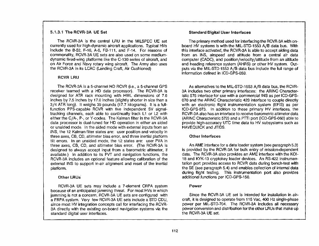
5.1.3.1 The RCVR-3A UE Set
The RCVR-3A is the central LRU in the MILSPEC UE set currently used for high-dynamic aircraft applications. Typical HVs include the B-52, F-16, A-6, FB-111, and F-14. For reasons of commonality, RCVR-3A UE sets are also used on some mediumdynamic fixed-wing platforms like the C-130 series of aircraft, and on Air Force and Navy rotary wing aircraft. The Army also uses the RCVR-3A in its LCAC (Landing Craft, Air Cushioned)
RCVR LRU
The RCVR-3A is a 5-channel HD RCVR (i.e., a 5-channel GPS receiver teamed with a HD data processor). The RCVR-3A is designed for ATR rack mounting with HWL dimensions of 7.6 inches by 7.5 inches by 17.0 inches (slightly shorter in size than a 3/4 ATR long). It weighs 39 pounds (17.7 kilograms). It is a fullfunction PPS-capable RCVR with five independent SV signaltracking channels, each able to continually track L 1 or L2 with either the C/A-, P-, or Y-codes. The Kalman filter in the RCVR-3A data processor is dual-tuned for HD operation in either an aided or unaided mode. In the aided mode with external inputs from an INS, the 12 Kalman filter states are: user position and velocity in three axes, CB, CD, altimeter bias error, and three inertial platform tilt errors. In an unaided mode, the 12 states are: user PVA in three axes, CB, CD, and altimeter bias error. (The RCVR-3A is designed to always accept input from a barometric altimeter, if available.) In addition to its PVT and navigation functions, the RCVR-3A includes an optional feature allowing calibration of the external INS to support in-air alignment and reset of the inertial platform.
Other lRUs
RCVR-3A UE sets may include a 7-element CRPA system because of an anticipated jamming threat. For most HVs in which jamming is not a concern, RCVR-3A UE sets are configured with a FRPA system. Very few RCVR-3A UE sets include a STD CDU, since most HV integration concepts call for interfacing the RCVR-3A directly with the existing on-board navigation systems via the standard digital user interfaces.
112
Standard Digital User Interfaces
The primary method used for interfacing the RCVR-3A with onboard HV systems is with the MIL-STD-1553 A/B data bus. With this interface activated, the RCVR-3A is able to accept aiding data from an INS, airspeed and altitude from a central air data computer (CADC), and position/velocity/attitude from an altitude and heading reference system (AHRS) or other HV system. Outputs via the MIL-STD-1553 A/B data bus include the full range of information defined in ICD-GPS-059.
As alternatives to the MIL-STD-1553 A/B data bus, the RCVR-3A includes two other primary interfaces: the ARING Characteristic 575 interface for use with a commercial INS as per ICD-GPS-070 and the ARING Characteristic 429 interface to couple directly with an electronic flight instrumentation system (EFIS) as per ICD-GPS-073. In addition to these primary HV interfaces, the RCVR-3A also has an interface to receive barometric altimeter data (ARING Characteristic 572) and a PTTI port (ICD-GPS-060) able to provide high-accuracy UTC time data to HV subsystems such as HAVEQUICK and JTIDS.
Other Interfaces
An AME interface for a data loader system (see paragraph 5.3) is provided by the RCVR-3A for bulk entry of mission-dependent data. The RCVR-3A also provides an AME interface with the KOl-18 and KYK-13 cryptokey loader devices. An RS-422 instrumentation port provides access to RCVR data during bench-test with the SE (see paragraph 5.4) and enables collection of internal data during flight testing. This instrumentation port also provides additional .functions per ICD-GPS-150.
Power
Since the RCVR-3A UE set is intended for installation in aircraft, it is designed to operate from 115 Vac, 400 Hz single-phase power per MIL-STD-704. The RCVR-3A includes all necessary power conversion and distribution for the other LR Us that make up the RCVR-3A UE set.

RCVR-3A UE SET {MILSPEC)
CRPASYSTEM (USED IN HIGH-JAMMING ENVIRONMENTS)
FRPASYSTEM (USED IN LOW-JAMMING ENVIRONMENTS)
r------------,·-Cc----a•-. HOST VEHICLE NAVIGATION
RCVR-3A 1 .. -cc-----111•~ SYSTEM INTERFACES (MIL-STD-1553 OR ARINC 575)
.-------~ • 5-CHANNEL GPS RECEIVER DIGITAL FLIGHT INSTRUMENT
OUTPUT INTERFACE
G
I I I
' B • "1°D1· ~·· (3 • 11·)1· u.1·
G UlHllSl..I 5 e e
. OJ ['.f] CT] [!]
=~~-:. [11 [:;:! rrJ ~·'" ~ I.Tl [II a ·r=r; El OJ [;)
STD CDU {OPTIONAL)
• HD DATA PROCESSOR
t t DATA CRYPTOKEY
LOADER LOADER
t HV
POWER
INSTRUMENTATION PORT (RS-422)
113
(ARINC 429)
BAROMETRIC ALTIMETER (ARINC 572)
......... _,... PTTI PORT INTERFACE (ICD-GPS-060)
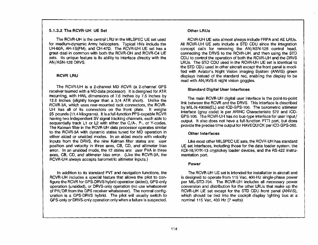
5.1.3.2 The RCVR-UH UE Set
The RCYR-UH is the central LRU in the MILSPEC UE set used for medium-dynamic Army helicopters. Typical HYs include the UH-60A, AH-1S(FM), and CH-47D. The RCYR-UH UE set has a great deal in common with both the RCYR-OH and RCYR-C4 UE sets. Its unique feature is its ability to interface directly with the AN/ASN-128 DRYS.
RCVR LAU
The RCYR-UH is a 2-channel MD RCYR (a 2-channel GPS receiverteamed with a MD data processor). It Is designed for ATR mounting, with HWL dimensions of 7.6 inches by 7.5 inches by 12.6 inches (slightly longer than a 3/4 ATR short). Unlike the RCYR-3A, which uses rear-mounted rack connectors, the RCYRUH has all of its connectors on the front plate. It weighs 25 pounds (11.4 kilograms). It is a full-function PPS-capable RCYR having two independent SY signal tracking channels, each able to sequentially track L1 or L2 with either the C/A-, P-, or Y-codes. The Kalman filter in the RCYR-UH data processor operates similar to the RCYR-3A with dynamic states tuned for MD operation in either aided or unaided modes. In an aided mode with velocity inputs from the DRYS, the nine Kalman filter states are: user position and velocity in three axes, CB, CD, and altimeter bias error. In an unaided mode, the 12 states are: user PYA in three axes, CB, CD, and altimeter bias error. (Like the RCYR-3A, the RCVR-UH always accepts barometric altimeter inputs.)
In addition to its standard PVT and navigation functions, the RCVR-UH includes a special feature that allows the pilot to configure the RCYR for GPS-DRYS hybrid operation (aided), GPS-only operation (unaided), or DRYS-only operation (no use whatsoever of PR/DR from the GPS receiver whatsoever). The normal configuration is a GPS-DRYS hybrid. The pilot will usually switch to GPS-only or DRYS-only operation only when a failure is suspected.
114
Other LRUs
RCYR-UH UE sets almost always include FRPA and AE LRUs. All RCYR-UH UE sets include a STD CDU since the integration concept calls for removing the AN/ ASN-128 control head, connecting the DRYS to the RCYR-UH, and then using the STD CDU to control the operation of both the RCYR-UH and the DRYS LRUs. The STD CDU used in the RCVR-UH UE set is identical to the STD CDU used in other aircraft except the front panel is modified with Aviator's Night Vision Imaging System (ANVIS) green displays instead of the standard red, enabling the display to be read with AN/AVS-6 night vision goggles.
Standard Digital User Interfaces
The main RCVR-UH digital user interface is the point-to-point link between the RCYR and the DRVS. This interface is described by MIL-N-49098(EL) and ICD-GPS-106. The barometric altimeter interface (gray code) is per ARINC Characteristic 572 and ICDGPS-106. The RCVR-UH has no bus-type interface for user input/ output. It also does not have a full-function PTTI port, but does provide the precise time output for HAVEQUICK per ICD-GPS-060.
Other Interfaces
Like most other MILSPEC UE sets, the RCVR-UH has standard UE set interfaces, including those for the data loader system, the KOl-18/KYK-13 cryptokey loader devices, and the RS-422 instrumentation port.
Power
The RCVR-UH UE set is intended for installation in aircraft and is designea to operate from 115 Vac, 400-Hz single-phase power per MIL-STD-704. The RCVR-UH includes all necessary power conversion and distribution for the other LRUs that make up the RCVR-UH UE set except for the STD CDU front panel (ANVIS), which should be tied into the cockpit display lighting bus at a nominal 115 Vac, 400 Hz (7 watts).

G ""' G • .1·01· ~·· G ••1·,.·111· G Q
e e . [[] ff] CT] CT]
·-~~\- ffl EB lTI -~.: ~ IT] [I] El r~r; a GJ §
STD CDU
RCVR-UH UE SET (MILSPEC)
FRPASYSTEM
~FRPA
~
RCVR-UH
111 2-CHANNEL GPS RECEIVER
l..,111(._----11•.._. DOPPLER RADAR VELOCITY SENSOR {DRVS) (MIL-N-49098 (EL))
• MD DATA PROCESSOR
, ... ._..,____ BAROMETRIC ALTIMETER
(ARINC 572)
• AN/ASN-128 FUNCTIONS
DATA CRYPTOKEY HV LOADER LOADER POWER
INSTRUMENTATION PORT (RS-422)
115
HAVEQUICK INTERFACE {ICD-GPS-060)

5.1.3.3 The RCVR-OH UE Set
The RCVR-OH is the central LRU in the MILSPEC UE set used by the Army for medium-dynamic Special Operations Force (SOF) helicopter applications. Typical HVs include the OH-58D, MH-60, and MH-47D. It shares a great deal of commonality with both the RCVR-UH and RCVR-C4 UE sets. Its unique feature is its almost total reliance on its MIL-STD-1553 data bus for user interfacing.
RCVR LAU
The RCVR-OH is a 2-channel MD RCVR (a 2-channel GPS receiver teamed with a MD data processor). The RCVR-OH LRU is designed for ATR rack mounting, with HWL dimensions of 7.6 inches by 7.5 inches by 12.6 inches (slightly longer than a 3/4 ATR short). It weighs 30 pounds {13.6 kilograms). It is a fullfunction PPS-capable RCVR having two independent SV signaltracking channels, each able to sequentially track L 1 and L2 with either the C /A-, P-, or Y-codes. The Kalman filter in the RCVR-OH data processor operates very similar to the RCVR-3A; it is dualtuned for MD operation in either aided or unaided modes. In an aided mode with external inputs from an INS, the 12 Kalman filter states are: user position and velocity in three axes, CB, CD, altimeter bias error, and inertial platform tilt errors. In an unaided mode, the 12 states are: user PVA in three axes, CB, CD, and altimeter bias error. Like the RCVR-3A, the RCVR-OH includes the optional feature allowing calibration of the external INS.
Physically almost identical to the RCVR-UH, the RCVR-OH has its connectors on the front plate rather than using rear-mounted rack connectors. It also has a front-mounted doghouse above the connectors to hold the keep-alive batteries and a time totalizing meter.
116
Other lRUs
RCVR-OH UE sets always include FRPA and AE LRUs. They do not include a STD CDU since the normal integration concept uses the HV's existing control and display capabilities by interfacing them with the RCVR-OH LRU via the MIL-STD-1553 data bus.
Standard Digital User Interfaces
The prime RCVR-OH digital user interface is the MIL-STD-1553 data bus. This interface is described by ICD-GPS-104. It supports the input of INS acceleration data as well as Doppler velocities, AHRS attitude and heading, and baro altimeter altitude to the RCVR-OH for aiding. Like the RCVR-UH, the RCVR-OH also provides a precise time output for HAVEQUICK per ICD-GPS-060, but not the full-function PTTI port.
Other Interfaces
The RCVR-OH includes the standard UE set interfaces for the GPS data loader system, the KOl-18/KYK-13 cryptokey loader devices, and the RS-422 instrumentation port.
Power
The RCVR-OH UE set is designed to operate from 115 Vac, 400-Hz single-phase power per MIL-STD-704. The RCVR-OH LRU provides tne power conversion and distribution for the AE.

RCVR-OH UE SET (MILSPEC)
FRPASYSTEM
~RPA
~
RCVR-OH .... ._ ____ --11,..~ HOST VEHICLE NAVIGATION
t
• 2-CHANNEL GPS RECEIVER
• MD DATA PROCESSOR
• 1553-0NLY INTERFACE
t t DATA CRYPTOKEY HV
LOADER LOADER POWER
INSTRUMENTATION PORT {RS-422)
117
SYSTEM INTERFACE (MIL-STD-1553)
HAVEQUICK INTERFACE (ICD-GPS-060)
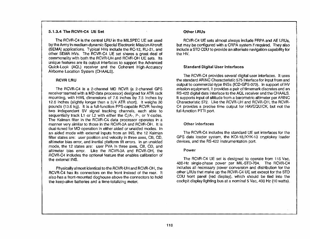
5.1.3.4 The RCVR-C4 UE Set
The RCVR-C4 is the central LRU in the MILSPEC UE set used by the Army in medium-dynamic Special Electronic Mission Aircraft (SEMA) applications. Typical HVs include the RC-12, RU-21, and other SEMA HVs. The RCVR-C4 UE set shares a great deal of commonality with both the RCVR-UH and RCVR-OH UE sets. Its unique features are its output interfaces to support the Advanced Quick-Look (AQL) receiver and the Coherent High-Accuracy Airborne Location System (CHAALS).
RCVR LRU
The RCVR-C4 is a 2-channel MD RCVR (a 2-channel GPS receiver teamed with a MD data processor) designed for ATR rack mounting, with HWL dimensions of 7.6 inches by 7.5 inches by 12.6 inches (slightly longer than a 3/4 ATR short). It weighs 30 pounds (13.6 kg). It is a full-function PPS-capable RCVR having two independent SV signal tracking channels, each able to sequentially track L1 or L2 with either the C/A-, P-, or Y-codes. The Kalman filter in the RCVR-C4 data processor operates in a manner very similar to those in the RCVR-3A and RCVR-OH. It is dual-tuned for MD operation in either aided or unaided modes. In an aided mode with external inputs from an INS, the 12 Kalman filter states are: user position and velocity in three axes, CB, CD, altimeter bias error, and inertial platform tilt errors. In an unaided mode, the 12 states are: user PVA in three axes, CB, CD, and altimeter bias error. Like the RCVR-3A and RCVR-OH, the RCVR-C4 includes the optional feature that enables calibration of the external INS.
Physically almost identical to the RCVR-UH and RCVR-OH, the RCVR-C4 has its connectors on the front instead of the rear. It also has a front-mounted doghouse above the connectors to hold the keep-alive batteries and a time-totalizing meter.
118
Other lRUs
RCVR-C4 UE sets almost always include FRPA and AE LRUs, but may be configured with a CRPA system if required. They also include a STD CDU to provide an alternate navigation capability for the HV.
Standard Digital User Interfaces
The RCVR-C4 provides several digital user interfaces. It uses the standard ARINC Characteristic 575 interface for input from and output to commercial-type INSs (ICD-GPS-070). In support of HV mission equipment, it provides a pair of timemark discretes and an RS-422 digital data interface to the AOL receiver and the CHAALS. It supports input of altitude from a barometric altimeter per ARING Characteristic 572. Like the RCVR-UH and RCVR-OH, the RCVRC4 provides a precise time output for HAVEQUICK, but not the full-function PTII port.
Other Interfaces
The RCVR-C4 includes the standard UE set interfaces for the GPS data loader system, the KOl-18/KYK-13 cryptokey loader devices, and the RS-422 instrumentation port.
Power
The RCVR-C4 UE set is designed to operate from 115 Vac, 400-Hz single-phase power per MIL-STD-704. The RCVR-C4 includes all necessary power conversion and distribution for the other LRU.s that make up the RCVR-C4 UE set except for the STD CDU front panel (red display), which should be tied into the cockpit display lighting bus at a nominal 5 Vac, 400 Hz (10 watts).

G EJ •• 2·111· '-'1"
G • J()I' l11'
G Q e e . m El ITJ l!.l =~~-:. ffi ~ rrJ ~UAf ~IT] [1)
aEreaGJ~ STD CDU
RCVR-C4 UE SET (MILSPEC)
FRPASYSTEM
~FRPA
~
RCVR-C4
• 2-CHANNEL GPS RECEIVER
• MD DATA PROCESSOR
• AQL/CHAALS INTERFACES
DATA CRYPTOKEY HV
1 .. -C.._ ___ .. ~.,,. COMMERCIAL-TYPE INS
(ARINC 575)
AQL/CHAALS INTERFACE (RS-422)
1 .. 1111(1111111----- BAROMETRIC ALTIMETER {ARINC 572)
1------11 .. HAVEQUICK INTERFACE (ICD-GPS-060)
LOADER LOADER POWER
INSTRUMENTATION PORT {RS-422)
119

5.1.3.5 The MAGR UE Set
The MAGR is an NDI RCVR for future high- or mediumdynamic aircraft where the size, weight, or power considerations preclude the use of a RCVR-3A. Because the MAGR is still early in the acquisition phase, it has not yet been given a U.S. military nomenclature. Typical HVs identified so far for a MAGA-based UE set include the F / A-18, F-117, and the AH-64.
RCVR LRU
There are actually two, slightly different versions of the MAGR LRU. One of them (the IF version) has the same antenna interfaces as the RCVR 3A. The IF MAGR is thus compatible with the standard MILSPEC FRPA and CRPA systems which perform outboard downconversion of the L 1 /L2 SV signals from RF to IF. The RF version of the MAGR does the RF-to-IF downconversion internally and is not compatible with the standard MILSPEC FRPA and CRPA systems. The RF MAGR is designed for use with external L-band antenna systems.
Like the RCVR-3A, the MAG Rs are 5-channel HD RCVRs. They are single LR Us with HWL dimensions of 6.8 inches by 3.2 inches by 12.0 inches (slightly narrower than a 3/8 ATR short), and are only about 1 /3 the size of the RCVR-3A LRU. They weigh about 13 pounds (6 kilograms). They are full function PPS units like the RCVR-3A, with five independent SV signal tracking channels capable of continuous L1 or L2 operation with either the C/A-, P-, or Y-codes. Unlike the RCVR-3A, however, their SA/A-S functions are designed around the use of a PPS security module (PPS-SM), which enables the MAGRs to remain unclassified even when the PPS keys are inserted. Their Kalman filters will operate in a manner very similar to the RCVR-3A as will their navigation and external sensor calibration functions.
Other LRUs
The IF MAGR UE sets include the same antenna system LRUs as RCVR-3A UE sets. RF MAGA UE sets do not include any antenna system LRUs. Neither version normally includes a STD CDU, since current HV integration concepts call for directly inter-
120
facing with existing HV navigation systems via the standard digital user interfaces.
Standard Digital User Interfaces
Like the RCVR-3A, the main MAGR digital interface will be the MIL-STD-1553A/B data bus. By use of connector strapping, this interface can be activated in one of two modes: either with Air Force/Navy standard message traffic and protocols per ICD-GPS-059 or using Army standard message traffic and protocols per ICD-GPS-104. The MAGR RCVRs will also include the ARINC Characteristic 429 EFIS output port per ICD-GPS-073. The main difference between the MAGRs and the RCVR-3A is that the MAGRs do not have the ARING Characteristic 575 interface with commercial INSs. They still have the PPTI port per ICD-GPS-060.
Other Interfaces
Also like the RCVR-3A, the MAG Rs will include standard UE set interfaces for the KOl-18 /KYK-13 cryptokey loader devices and the RS-422 instrumentation port. They do not have an interface for the GPS data loader system. (All data loading functions can still be accomplished via the MIL-STD-1553 data bus, however.)
A novel feature planned for the MAGRs is the capability to reprogram the data processor software by way of the RS-422 interface. This should minimize the overall logistics support costs for the MAGRs because they can be reprogrammed in the field, using a properly equipped laptop computer, instead of being returned to the factory.
Power
In addition to being smaller and lighter than the RCVR-3A, the MAGRs will use an advanced low-power design to minimize their impact on the aircraft's power system. They are both expected to draw only about 28 watts of HV 115 Vac, 400-Hz single-phase power. The MAGRs will provide the power conversion and distribution to other LRUs that make up the MAGA UE set.

CRPASYSTEM (USED IN HIGH-JAMMING ENVIRONMENTS)
1--------~ I I I
' G 1111
G •·i·o1·)4.r C3 • 11· 11· 11.1•
C3 l)ttll'Gll 0 e e
. lI1 crl B:J [!] :5~-:. ffi Erl rrJ ~·m~CT}(1] a'B9 EJGJ~ OPTIONAL STD CDU
MAGR UE SET (NDI)
RF INPUT (USED WITH EXTERNAL ANTENNA SYSTEMS)
FRPASVSTEM (USED IN LOW-JAMMING ENVIRONMENTS)
MAGR ...... ._ _____ ,....~ HOST VEHICLE NAVIGATION
• 5-CHANNEL GPS RECEIVER
1~-c---~~~•,....~ SYSTEM INTERFACE (MIL-STD-1553 A/B)
• HD DATA PROCESSOR
• REPROGRAMMABLE 1-------~
t t CRYPTOKEV HV
LOADER POWER
INSTRUMENTATION PORT (RS-422)
121
DIGITAL FLIGHT INSTRUMENT OUTPUT INTERFACE (ARINC 429)
PTTIPORTINTERFACE (ICD-GPS-060)

5.1.3.6 The RCVR-3S UE Set
The RCVR-3S is the central LRU in the MILSPEC UE set used for surface ships and for submarines where very rapid signal acquisition is required. Most ballistic missile submarines use a different type of UE set because of the need to interface with missile launch and control systems. Certain early installations have used the WRN-25 UE set, which is a commercial TransitOmega-GPS integrated set without PPS capabilities, instead of the RCVR-3S. The RCVR-3S UE sets are also used in certain Army watercraft applications.
RCVR LRU
The RCVR-3S is a 5-channel LD RCVR designed for 19-inch rack or tray mounting. Its HWL dimensions, including connectors, are 12.2 inches by 16.8 inches by 12.0 inches. It weighs 50 pounds (23 kilograms). It is a full-function PPS RCVR having five independent SV signal tracking channels, each able to continually track L1 or L2 with either the C/A-, P-, or Y-codes. The Kalman filter in the data processor supports 12 states and is tuned for LD operation with external aiding inputs of acceleration from the shipboard INS (SINS), heading/pitch/roll from a ship's gyros, and velocity (water speed) from a ship's log. When external aiding inputs are not available, the RCVR-3S automatically reverts to unaided operation. The RCVR-3S operates at constant MSL altitude for aiding purposes. In addition to its PVT and navigation functions, it allows calibration of the external INS to support at-sea alignment and reset of the inertial platform. A special feature of the RCVR-3S, not shared by other RCVRs, is its BITE, which enables it to perform off-line fault isolation to the failed SRU for itself and for other LRUs which make up the RCVR-3S UE set.
Other LRUs
The RCVR-3S UE sets for surface ship applications use a FRPA-ground plane (FRPA-GP) and AE LRUs instead of a CRPA system. The FRPA-GP is a combined FRPA/ground plane unit which houses the AE and is used for mast-mounted installations.
122
The RCVR-3S UE sets for submarine applications omit the FRPAGP, instead using a modified version of the existing BRA-34 antenna (or equivalent) in one of the extendable masts. For these installations, the AE LRU is still needed. RCVR-3S UE sets always include at least one CDU and often two. In dual CDU installations, one of the CDUs functions as the master for controlling UE set operation while the other functions as the slave and can only display selected data. Each CDU is housed within its own HVIA to allow overhead or table-top mounting at distances up to 100 meters away from the RCVR-3S LRU.
Standard Digital User Interfaces
The RCVR-3S provides shipborne point-to-point interfaces per MIL-STD-1397, both the Naval Tactical Data System (NTDS) Type A (SLOW) and Type B (FAST), as detailed in ICD-GPS-176. In addition to the NTDS digital interfaces, the RCVR-3S also supports analog interfaces for input of ship's attitude and water speed.
A special application for the PTII port is found on many submarines with an on-board atomic clock. This bi-directional interface not only allows synchronization of the atomic clock to UTC as determined by the RCVR-3S, but it also enables the RCVR-3S to keep itself precisely synchronized to UTC as accurately maintained by the atomic clock. This cross-synchronization scheme is used to support the low time initialization uncertainty required for hot starts and thus minimizes the submarine's antenna exposure time when the antenna pops up for a PVT fix (i.e., the REAC-2 and TTFF-2 times apply).
Other Interfaces
The RCVR-3S includes the same additional interfaces as the RCVR-3A.
Power
The RCVR-3S UE set is designed to operate from standard 115 Vac, 60-Hz power. ·The RCVR-3S does all power conversion and distribution except for CDU lighting.
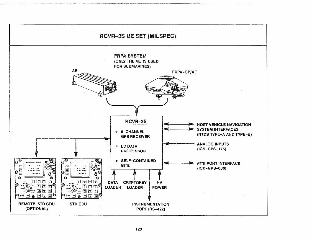
r----------1 I
+
REMOTE STD CDU (OPTIONAL)
STD CDU
RCVR-3S UE SET (MILSPEC)
FRPASYSTEM (ONLY THE AE IS USED FOR SUBMARINES)
RCVR-3S
e 5-CHANNEL GPS RECEIVER
• LD DATA PROCESSOR
• SELF-CONTAINED BITE
FRPA-GP/AE
•"'"-.Cllllli-----111)1itr- HOST VEHICLE NAVIGATION •"'"-.Cllllli-----111)1itr- SYSTEM INTERFACES
(NTDS TYPE-A AND TYPE-B)
1·~111111--------- ANALOG INPUTS (ICD-GPS-176)
1 4--.Clllllllli-------~...-- PTTIPORTINTERFACE (ICD-GPS-060)
DATA CRYPTOKEY HV LOADER LOADER POWER
INSTRUMENTATION PORT (RS-422)
123

5.1.3.7 The RPU-1 UE Set
The APU-1 is the central LAU in the MILSPEC UE set used for manpack (AN/PSN-8) and vehicular (AN/VSN-8) applications. In a rnanpack configuration, there is no HV per se (other than the operator). In a vehicular configuration, typical groundborne HVs include the M998 High-Mobility Multipurpose Wheeled Vehicle (HMMWV) and the M1009 Commercial Utility Cargo Vehicle (CUCV), while typical waterborne HVs are most Army watercraft. A unique feature of the APU-1 is its ability to work from an internal prime power battery in a manpack configuration. In the vehicular configuration, an HVIA will generally be required to convert HV power instead of relying on the internal battery.
RCVR LRU
The APU-1 is a 1-channel LO ACVA designed to be mounted on a pack frame or HVIA but it can also be carried in a rucksack. Its HWL dimensions (including handles) are 10.2 inches by 5.0 inches by 11.9 inches. Including the prime power battery, but not the CDU or antenna, the APU-1 weighs 15.3 pounds (7.9 kilograms). It is a full-function PPS-capable ACVA employing a single tracking channel able to sequentially track on L 1 or l2 with either the C/A-, P-, or Y-codes. The Kalman filter in the data processor is tuned for LO operation in an unaided mode. The eight dynamic states are: user position and velocity in three axes, plus CB and CD. The APU-1 does, however, support quasi-aided operation, allowing the operator to indicate the unit is stationary or is operating at a constant altitude. When the stationary indication is made, the APU-1 enters a survey mode, using the fact that the velocities are zero to alter the Kalman filter into a five-state operation (position plus CB and CD), and thereby improves position-fixing accuracy and resistance to jamming. The APU-1 supports navigation as well as PVT determination, but its capacity for waypoint storage is limited to 38 stationary points/marks.
124
Other LRUs
APU-1 UE sets include a collapsible FAPA that does not require the use of an AE LAU, but should be located within 24 inches of the APU-1 in vehicle installations. In manpack applications, the FAPA antenna attaches directly to the APU-1 case via a flexible extender. The APU-1 UE set also includes a hand-held manpack/vehicular (M/V) CDU featuring pushbutton operation and a liquid crystal display. The display provides integral backlighting for night operation and can be used with night vision goggles. In vehicular applications, the M/V CDU can be remotely located using an extension cable. In manpack applications, the M/V CDU plugs directly into the RPU-1 using a 39-inch-long pendant cable. This M/V CDU (as well as the STD CDU for air and sea applications) is compatible with position coordinate entry /display in the standard Military Grid Reference System (MGRS).
Standard Digital User Interfaces
The RPU-1 provides only one standard digital user interface. Like the 2-channel RCVRs, it provides the precise time output for HAVEQUICK, but not the full-function PTII port.
Other Interfaces
The RPU-1 includes the interfaces for the KOl-18/KYK-13 cryptokey loader devices and the RS-422 instrumentation port. It has no provision for the GPS data loader system.
Power
The RPU-1 UE set is designed to operate using a BA5590 or a BB590 battery as its prime power source. In vehicular applications, this battery may be replaced with a source of 28-Vdc power (nominally via an HVIA). The expected life of the prime power battery in continuous operation is 12 hours. In intermittent operation (i.e., when TISF applies), the expected life is 36 hours for a one-to-nine duty cycle (NAY-to-STANDBY ratio). The RPU-1 also uses keep-alive battery.
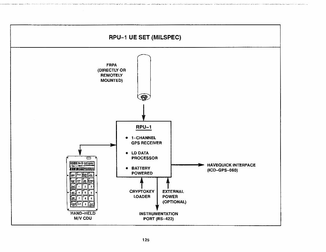
t::l •
HAND-HELD MNCDU
RPU-1 UE SET (MILSPEC)
FRPA (DIRECTLY OR
REMOTELY MOUNTED)
RPU-1
• 1-CHANNEL GPS RECEIVER
• LO DATA PROCESSOR
• BATTERY POWERED
CRYPTOKEY LOADER
EXTERNAL POWER (OPTIONAL)
INSTRUMENTATION PORT (RS-422)
125
HAVEQUICK INTERFACE (ICD-GPS-060)

5.1.3.8 The Tl-420 UE Set
The Tl-420 is the commercial name of the central LRU in an NDI UE set for manpack (AN/PSN-9) and vehicular (AN/VSN-9) applications. This was the first UE set procured under the GPS NDI program. Candidate MjV applications for this UE set are basically the same as for the RPU-1 UE set. Like the RPU-1 UE set, the Tl-420 UE set is able to work from an internal prime power battery (BA6598 or BA5598 or equivalent) in a manpack configuration. In the vehicular configuration an HVIA will be required to convert HV power instead of relying on the internal battery.
RCVR LRU
The Tl-420 is a 5-channel MD RCVR (a 5-channel GPS receiver teamed with a MD data processor). It is designed to be mounted on a pack frame or HVIA but can also be carried in a rucksack. Its HWL dimensions are 6.5 inches by 8. 7 inches by 5.3 inches. Including the prime power battery, CDU, and antenna, the Tl-420 RCVR weighs 10.4 pounds (4.7 kilograms). It is a partial-PPScapable (SA but not A-S) RCVR employing five SV tracking channels, each able to continuously track the L1 signal with C/Acode (no P- or Y-code tracking). The Kalman filter in the data processor is tuned for MD operation in an unaided mode. The eight dynamic states are user position and velocity in three axes, plus CB and CD. Like the RPU-1, the Tl-420 RCVR supports quasi-aided operation by enabling the operator to indicate stationary or constant-altitude operation. The Tl-420 RCVR supports navigation as well as PVT determination. Its capacity for waypoint storage is greater than the RPU-1, with up to 100 stationary points and up to 4 courses of 1 O points each supported. A significant difference between the RPU-1 and Tl-420 RCVRs is the latter does not require a warm-up period for its internal quartz clock; the Tl-420 begins outputting PVT fixes within 2 minutes of set turn-on.
126
Other LRUs
The Tl-420 UE set includes an integrated FRPA/AE LAU that can be located up to 100 feet away from the Tl-420 RCVR in vehicle installations. In manpack applications, the FRPA/AE system attaches directly to the Tl-420 case in a low-profile configuration. The Tl-420 UE set includes a separate hand-held CDU featuring pushbutton operation and a liquid crystal display. The display provides integral backlighting for night operation and can be used with night vision goggles. In vehicular applications, the CDU can be remotely located using an extension cable. In manpack applications, the CDU plugs directly into the RPU-1 using a pendant cable,·and can be stored in a recessed area in the RCVR case. This CDU is also compatible with MGRS position coordinate entry and display.
Standard Digital User Interfaces
The Tl-420 LRU provides none of the standard digital user interfaces.
Other Interfaces
The Tl-420 includes the standard interfaces for the KOl-18/KYK-13 cryptokey loader devices and an RS-422 instrumentation port.
Power
The Tl-420 UE set is designed to operate using a BA6598 or a BA5598 battery as its prime power source. In vehicular applications, this battery may be replaced with a source of 28-Vdc power (nominally via an HVIA). The expected life of the prime power battery in continuous operation is 20 hours. In intermittent operation (i.e., when TISF applies). the expected life is 160 hours for a one-to-eight duty cycle (NAV-to-STANDBY ratio).

HAND-HELD CDU
FRPA/AE (DIRECTLY OR
REMOTELY MOUNTED)
CURRENT LO :'ri ALT +000153 mE ~l: N 33° 00'03 9·,.,. W096° 59·49:7·~~
Tl-420 UE SET (NDI)
Tl-420
• 5-CHANNEL GPS RECEIVER
e MD DATA PROCESSOR
• BATTERY POWERED
CRYPTOKEY EXTERNAL LOADER POWER
(OPTIONAL}
INSTRUMENTATION PORT (RS-422)
127

5.1.3.9 The SLGR UE Set
SLGR is the generic name of the only LAU in the very lightweight NDI UE sets for M/V use. Candidate HVs for these UE sets are basically the same as for the RPU-1 UE set. Like the RPU-1 UE set, the SLGR UE set is able to work from prime power batteries (see below) in a manpack configuration. In the vehicular configuration, the use of an HVIA is usually not required to convert HV power for use. SLGRs may be procured from a range of different manufacturers; the one discussed here is the TRIMPACK unit built by Trimble Navigation. It is representative of the majority of SLGR UE sets procured so far, but there can be significant differences between this unit and others (e.g., the SLGR unit built by Magellan Systems).
RCVR LAU
The TRIMPACK SLGR is a 3-channel LD RCVR. It is designed for hand-held operation but may be mounted on flat surfaces with the use of an HVIA bracket. The SLGR RCVR is integrated with a FRPA and a CDU in a single LAU package. The combined HWL dimensions-including battery pack-are 2.0 inches by 5.4 inches by 9.5 inches. The total weight for the combined package is 4.2 pounds (1.9 kg). It is strictly an SPS-only RCVR (no PPS capabilities) employing three tracking channels able to sequentially track up to six SVs on L 1 with the C/ A-code. The Kalman filter in the data processor portion of the SLGR RCVR is tuned for LD operation in an unaided mode. The eight dynamic states are: user position and velocity in three axes, plus CB and CD. It implements an automatic stationary mode when not moving and an automatic altitude hold mode when there are less than four SVs visible. The SLGR supports navigation functions as well as PVT determination. Its waypoint storage capacity of up to 1 ,089 stationary points is greater than both the RPU-1 and Tl-420 RCVRs. An instant-on feature similar to that of the Tl-420 allows the SLGR RCVR to begin outputting PVT fixes within about 2.5 minutes after set turn-on.
128
Other LRUs
The TRIMPACK SLGR can use an optional external FRPA/AE unit that can be located up to 20 feet away in vehicle Installations (even farther away with low-loss cabling). The SLGR's Integral CDU features a front-mounted rotary switch plus snap-action data levers for data entry along with a liquid crystal display. The display provides integral backlighting for night operation and can be read with night vision goggles. It is compatible with MGRS position coordinate entry and display along with latitude and longitude for horizontal operations.
Standard Digital User Interfaces
SLGRs provide none of the standard digital user interfaces.
Other Interfaces
SLGRs also provide none of the other typical UE interfaces. The TRIMPACK SLGR does, however, include a data port for transferring data to/from other SLGR units or for use with an instrumentation system. SLGR also offers a one-pulse-per-second timing output.
Power
The SLGR is designed to operate using a wide range of battery packs as its prime power source. It is compatible with a twin-pack containing either two BA5800 (military) or two D cell (commercial) lithium batteries. It is also capable of operation using rechargeable nickel-cadmium (NiCad) batteries in a built-in case or using an eight-pack of AA cells. The expected life of the prime power battery packs at 23°C are: 21 hours for BA5800, 18 hours for commercial D cells, 6 hours for NiCad, and 4 hours for AA cells. In vehicular applications, the battery packs may be replaced with a source of 9 to 32 Vdc power at 5 watts.

SLGR UE SET (NDI)
OPTIONAL EXTERNAL FRPA/AE
(FOR REMOTE MOUNTING)
SLGR
• 3-CHANNEL GPS RECEIVER
• LD DATA PROCESSOR
• INTEGRAL RCVR, CDU, FRPA
• BATTERY POWERED
129
I HV POWER (OPTIONAL)
SLGR-TO-SLGR DATA PORT (OPTIONAL)

5.1.3.10 The PLGR UE Set
PLGR is the generic name for the only LRU in a follow-on effort to procure a very lightweight NDI UE set with PPS capabilities for M/V use. The PLGR is still in the early acquisition phase of the GPS NDI program. Candidate HVs for this UE set are basically the same as for the SLGR.
The current concept for the PGLR is much like the SLGRexcept with PPS capabilities. This will, as a minimum, include SA. The decision on whether the PLGR will require A-S capability has not yet been made. Like the SLGR, the PLGR will be required
130
to work from a prime power battery in a manpack configuration. In a vehicle configuration, the PLGR will operate from available HV power.
A feature which is very similar to one found in the MAGA, the PLGR software will also be field reprogrammable to minimize overall logistics costs over its life cycle.
The PLGR may be procured from one or more different manufacturers. Under the current PLGR schedule, the request for proposals should be sent to industry in the fall of 1991 with contract awards the following spring. Further information on the PLGR will be available from the GPS JPO at that time.

PLGR UE SET {NDI)
? II
131
5.2 HOST VEHICLE INTERFACE ADAPTORS
The HVIA comprise those items of the User Segment which mechanically and electrically adapt the particular UE set to the particular HV and its mission, but which cannot be considered a direct part of the UE set or the HV. Common HVIA include equipment mounts, connectors, and specialized electronic units needed to convert between the input-output used by the UE set and those used by the HV. In standard U.S. Air Force terminology, the HVIA are referred to as the "Group A kit" items, and the UE set LRUs as the "Group B kit" items.
In airborne applications, HVIA commonly consist of one of a number of shock-isolated ATR racks. All of the airborne ATR racks include a pair of front-mounted holddowns to engage the RCVR LRU's MS 14108-12C hooks and enable the unit to be mounted in either an upright or inverted orientation. (Vertical mounting of the ACVA LAU is not possible because of constraints associated with its ovenized quartz clock.) The ATA racks for the RCVA-3A have rear enclosures to enable connection between the unit's rearmounted DOD-C-83527 rack-to-panel interface connectors and the HV wiring harness. The typical weight for these HVIA is about 7 pounds (3 kilograms). Connector strapping to activate the various standardized digital user interfaces is normally handled by jumpers in the HV wiring harness instead of by the HVIA.
In seaborne applications, the HVIA usually consist of enclosures or consoles for the LRUs that make up the UE set. A remote console unit (ACU) is used to house the primary CDU as well as a secondary CDU whenever called for by the ship's integration concept. The RCUs enable the CDUs to be mounted in several orientations: table-top, overhead, and bulkhead. The RCU provides additional environmental protection for the CDUs, particularly with respect to hull shock and dripping water.
Ground vehicle HVIA consist of a wide range of brackets for mounting the MILSPEC manpack CDU and antenna LRUs on a
132
variety of surfaces as well as a vehicular power adaptor (VPA) and a vehicle mount (VM). The VPA transforms and filters ground vehicle (HMMWV, CUCV, etc.) power to generate the regulated voltages needed by the UE set when HV power is used instead of relying on the UE set's internal battery. The VM provides the holddown mechanism for the RCVR LAU and the VPA in ground vehicle applications. There are also NDI HVIA components for ground vehicle use.
In certain airborne applications, a specialized HVIA unit is used to drive analog flight instruments using a RCVR's ARINC 429 digital interface output. This HVIA is known as the GPS "Digital-toAnalog Converter" or DAC. The GPS DAC is a separate avionics LRU in its own right. Procurement of the GPS DAC from Harris is being managed by the U.S. Air Force Aeronautical Systems Division (ASD) at Wright-Patterson AFB, OH. Paired with the DAC, the UE-generated navigation outputs relative to a waypoint can be converted to drive an aircraft's analog flight instruments and annunciators in a manner emulating an AAN-118 TACAN receiver. The TACAN output emulation is close enough (including conversions from true to magnetic heading) such that users are able to switch back and forth between GPS and T AGAN as the source of navigation information display almost without notice. The operational differences between navigating with the UE-DAC versus the T ACAN are:
• GPS waypoint data entry /selection must be performed using the UE set CDU instead of the TACAN frequencyselection knob and horizontal situation indicator (HSI) desired course set knob.
• The UE set can use a variety of RNAV routes, including TO-TO and those defined by a moving waypoint, instead of just the TACAN's FROM-TO routes.
• The UE-DAC can provide vertical navigation information to attitude director instruments whereas the TACAN is limited to horizontal navigation only.
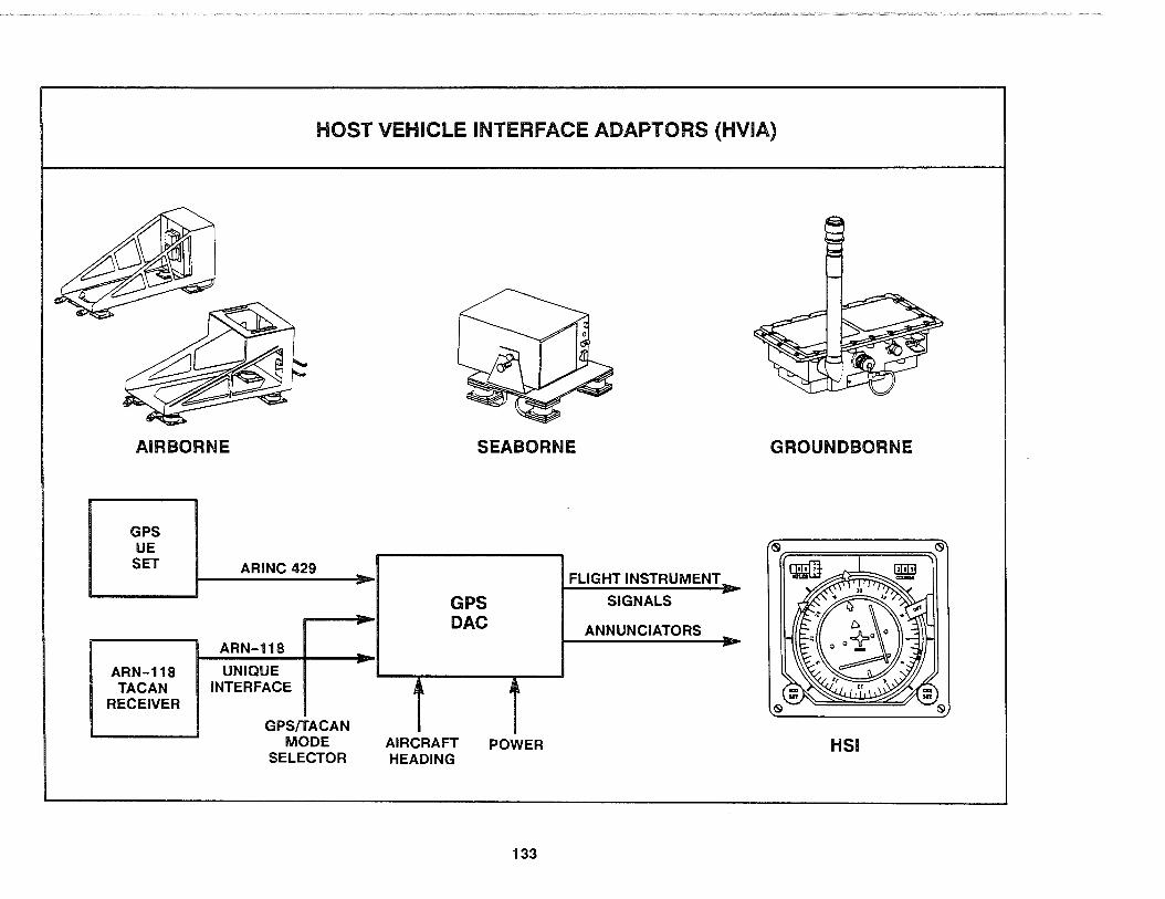
HOST VEHICLE INTERFACE ADAPTORS (HVIA)
AIRBORNE
GPS UE SET
ARN-118 TACAN
RECEIVER
ARINC 429
ARN-118
UNIQUE INTERFACE
GPS/TACAN MODE
SELECTOR
--
----
SEABORNE GROUNDBORNE
FLIGHT INSTRUMENT_
GPS SIGNALS
DAC ANNUNCIATORS --
j' j' AIRCRAFT POWER HSI HEADING
133

5.3 AUXILIARY MISSION EQUIPMENT
Like HVIA, AME comprise User Segment items that are not part of the UE set or the HV. Instead, they are ancillary equipment used to simplify UE set operation or to enhance the mission utility of the GPS PVT information. The range of AME includes waypoint data management systems, PPS cryptokey loading devices, and mission planning systems. None of the AME items are absolutely required, but most users find them nearly indispensable.
For the UE set to perform its navigation functions, the data defining a waypoint must first be entered into the UE set's memory. Both the digital and CDU UE set user interfaces allow the entry of waypoint data one point at a time. But entering the waypoint data one point at a time is not very convenient, especially if one tries to read the waypoint information from a map or a chart and then key it in using the CDU in the cockpit in midflight. As a result, the normal process for handling waypoint data is for the user to enter the data for every waypoint that might be needed for the mission into the UE set memory before departure and then, during the mission, selecting the desired waypoint using its mnemonic identifier.
However, consider the pre-mission workload this scheme imposes on the driver, pilot, navigator, crew chief, etc. Since UE sets can hold data for 200 waypoints (more in some NDI units), manually entering the data for every waypoint that might be needed is a tedious task and prone to keystroke errors. To simplify the waypoint data entry process, an AME system known as the "GPS data loader" was created. It consists of a loader terminal, data modules, and receptacles. The loader terminal is a computer-based workstation designed to facilitate waypoint management (data entry, modification, and validation) in a userfriendly manner. The data modules are solid-state memory cartridges which can be plugged into both the loader terminal and the receptacles. When a data module is plugged into the loader terminal, the operator is able to select the desired waypoints, then build and download an entire set of waypoint data into the
134
module. Once the download is complete, the data module can be removed from the loader terminal, carried out to the aircraft, and plugged into the receptacle installed in the cockpit. Since the receptacles are normally wired directly to the UE sets, the modulereceptacle combination becomes sort of an external UE set memory. And with waypoint data already preloaded in the data module, the UE set can automatically read in the necessary information at turn-on.
As an alternative to the GPS data loader system, UE sets with a MIL-STD-1553 digital user interface are capable of using the HV's own data loader system to enter the waypoint data into the UE set memory via the 1553 interface.
Other data needed by the UE set are also often entered via the GPS or HV data loader systems in addition to waypoint data. This includes lever arm distances from the UE set antenna to the HV navigation reference point (e.g., its center of gravity or INS), SV almanac data, and the PPS keys. Fault isolation results from the UE set BIT can also be loaded back into the data loader system memory (GPS data module or HV memory device) to support post-mission maintenance.
Much like a miniature data loading system, PPS cryptokey loading devices are AME used to facilitate the entry of PPS keys into PPS-capable UE sets. Even though PPS keys can be manually entered via the CDU or by certain standard digital user interfaces, use of a PPS key loading devices is preferred since it makes the entry much easier, preventing keystroke errors as well as providing an additional level of security. All PPS-capable UE sets have an external connector that interfaces with either of the two common PPS key loading devices: the KOl-18 tape reader or the KYK-13 electronic key loader. As with other AME, these devices are not part of the UE set. They are separate and distinct. If you are authorized to receive PPS keys, you may obtain your KOl-18 and KYK-13 devices by ordering them through COMSEC channels. They are not available through the GPS JPO.

AUXILIARY MISSION EQUIPMENT (AME)
GPS DATA LOADER
DOWNLOAD WAYPOINT DATA
REVIEW FAULT-ISOLATION DATA
RETURN~ ~ DATA MODULE ~ , TO LOADER TERMINAL
PPS KEY LOADING DEVICES
PPS KEY (PUNCHED TAPE)
KOl-18 TAPE READER
135
.L?POST-MISSION, REMOVE DATA MODULE
FROM COCKPIT
~ q(~) -KYK 13
ELECTRONIC KEY LOADER
I • UE SET - PPS KEY .
EXTERNAL CONNECTOR

The AME for mission planning provides the user end of the Control-to-User interface described in paragraph 3.4.5 (ORMS). It typically consists of a general-purpose desktop computer along with various software programs to forecast the PVT accuracy and related performance quantities for a particular type of UE set over a geographic region or a specific location during a user-defined time window.
These performance forecasts are needed by both mission planning and UE set maintenance personnel. Mission planners need the forecast information in advance to ensure adequate GPS coverage for missions relying on GPS as the primary HV navigation aid. If the forecast indicates a DOP hole will be present over the mission region during the planned mission time, then the planner will need to examine just how deep the DOP hole will be and whether the expected GPS accuracy will still satisfy the required navigation accuracy for the mission phase planned for that region/time. This awareness of the planned mission phase is critical since much greater accuracy is required for navigating a narrow channel on a foggy, moonless night than for navigating the open seas on a sunny day. If the forecast DOP hole is shallow and the resulting accuracy is still sufficient, then the mission planner need do nothing. But if the DOP hole is deep and the forecast GPS accuracy is not adequate to safely perform the particular mission phase, the mission planner will be faced with three options:
1. Plan the mission based on the use of an alternate source of navigation information for the location/time of the DOP hole (visual sightings, coasting on an INS, altimeter aiding of the UE set, etc.).
2. Reroute the mission to avoid the geographic area of the DOP hole Gust like routing around a storm).
3. Adjust the mission phase start/end times to avoid the period of the DOP hole (often the easiest, since it may take no more than adjusting the critical mission phase time a few minutes earlier or later).
136
Another use of in-advance forecasting is to determine the "best-time-on-target". This application is common when planning weapon delivery missions, but it can also be needed in other circumstances which also require maximum accuracy. In this type of forecasting, the target coordinates are normally entered into the mission-planning software and an accuracy forecast is generated covering the total potential time window at the specific location. The best (most accurate) times are then found by visually examining the forecast accuracy results. Mission planners will often be able to choose from several different time periods that offer nearly equal maximum accuracy during a day.
After-the-fact GPS performance forecasts are needed by UE maintenance personnel to distinguish between user-reported performance problems caused by UE set malfunctions and those caused by SV malfunctions. Many post-mission maintenance actions can be avoided altogether by judicious use of after-the-fact forecasting. If an SV suddenly fails on orbit, then user reports of unexpectedly poor UE set performance should be anticipated from affected regions of the world beginning at the SV failure time. None of these reports should result in UE set maintenance. But when the user reports a problem and an after-the-fact GPS accuracy forecast indicates no SY-related reason for the problem, the UE set should be checked since it has most likely malfunctioned.
There are important parallels between what the UE set software does for real-time performance monitoring versus what the mission-planning software does for in-advance and after-the-fact forecasting. The UE set gets its SV almanac data directly from the broadcast SIS and observes SV status in real time. The missionplanning system gets its SV almanac-type data and scheduled/ unscheduled SV status change information from an ORMS node. Since these inputs are functionally equivalent, the mission-planning software can use the same basic algorithms as the particular type of UE set to generate high-fidelity forecasts for its PVT valid/invalid warning flag, FOM, and expected UNE/UHNE/UVNE values as well as DOP hole depth for the selected set of four SVs. The main limitation on the forecast fidelity is the inability of mission planning software to predict UE-localized phenomena such as UE set LAU failures, jamming, and antenna misorientation.

PARALLELS BETWEEN UE SET AND MISSION-PLANNING AME
SV ALMANAC DATA, REAL-TIME SV STATUS
UESET
RCVR
DIGITAL --------... D~ •••• ... ... CDU
MISSION-PLANNING AME
ORMS NODE SV ALMANAC-TYPE DATA,
SCHEDULED SV STATUS CHANGES, UNSCHEDULED SV STATUS CHANGES
• I 11111 RJ=-=D=H /DL JD\
137
REAL-TIME PERFORMANCE MONITORING
• PVT VALID/INVALID WARNING
• FOM (1-9) • UNE/UHNE/UVNE • DOP HOLE DEPTH
IN-ADVANCE AND AFTER-THE-FACT
PERFORMANCE FORECASTS
• PVT VALID/INVALID WARNING
• FOM (1-9) • UNE/UHNE/UVNE • DOP HOLE DEPTH
5.4 SUPPORT EQUIPMENT
GPS SE comprise those User Segment items needed for supporting the UE sets. SE includes intermediate-level and depotlevel maintenance equipment. SE can also include those items needed to support integration of the UE sets into the various HVs and to enable their initial checkout in the HV's Systems Integration Laboratory (SIL) and follow-on flight/sea/field trials. Anq, although not really equipment per se, the technical manuals (TMs) needed to support the UE sets are included in this category because of their importance.
As described earlier, the MILSPEC UE set concept for organizational maintenance relies primarily on the UE set's internal BIT to identify the failed LRU. At the next level up (intermediate maintenance), fault isolation to the failed SRU is based on the use of an ITS. There are three different ITS units, known as ITS-A, ff SB, and ITS-C. Each of the three ITSs consists of a mainframe unit that is common to all and a series of plug-in modules that are peculiar to each. The ITS-A has a plug-in module to support SRU fault isolation for the three main LRUs that make up the AN/PSN-8 and AN/VSN-8 UE sets and their associated HVIA (the RPU-1, the manpack CDU, and the VPA). The manpack FRPA LRU is considered a non-repairable assembly that does not require further fault isolation. The ITS-B has a plug-in module to support SRU fault isolation for the three 2-channel RCVRs (the RCVR-UH, RCVROH, and RCVR-C4), the STD CDU, and the AE used with FRPAs in airborne platforms. The ITS-C has the plug-in module for the RCVR-3A, the STD CDU, and the AEs used with CRPAs and FRPAs in airborne platforms. No ITS is required for the RCVR-3S UE set components since the RCVR-3S has its own internal BITE to accomplish SRU fault isolation. The ITSs do their own internal fault isolation to prevent erroneous results. In addition to the ITSs, which are peculiar to GPS, the AN/USM-486 multimeter, the AN/USM-488 oscilloscope, and a battery charger are common support equipment (CSE) needed for intermediate maintenance.
138
The next level up from intermediate maintenance is depot maintenance. This is where fault isolation to the failed hardware component is performed and the repair /discard decision is made. It has been decided there will be multiple organic depots for the MILSPEC equipment. They will each use the U.S. Army's Integrated Family of Test Equipment (IFTE) as depot-level ATE. WR-ALC will be the Air Force depot and will develop the common test program sets (TPSs). Tobyhanna Army Depot (TOAD), PA will be the Army depot and will develop Army-unique TPSs. The Navy will not establish a depot capability. These depots should reach their initial operational capability (IOC) by September 1992 when Rockwell-Collins' PRW expires for the LRIP equipment. After IOC, MILSPEC LRUs for which an organic repair capability has not yet been established at the depots with their SE will be processed via interim contractor support (ICS) arrangements with RockwellCollins.
Just as with the MILSPEC hardware, the MILSPEC UE and ITS software also requires support. WR-ALC has been selected as the site for an ISF to provide this organic capability. This ISF will contain the full range of SE needed to support the MILSPEC software over the long term.
The SE necessary for UE integration, Sil checkout, and followon flight/sea/field trials is dependent on the particular HV. Typical SE required for these functions includes specialized UE set interface emulators, single-channel signal generators (SCSGs), GPS antenna couplers, buffer boxes (for interfacing the UE set RS-422 instrumentation port to various data collection and analysis systems), data tape recorders, telemetry systems, jammers, and data analysis stations (DASs) for quick-look examination. Selecting and obtaining the right SE is difficult; most HV managers should thus refer to a service-specific integration/test agency for assistance. For Air Force HVs, one such source is 6585th Test Group at Holloman AFB, NM; for Navy HVs, the Naval Air Development Center (NADC), PA is often used; and for Army HVs, the Army DPM at the GPS JPO is a good starting point.

USER SEGMENT SUPPORT EQUIPMENT (SE)
Organization-Level Maintenance
Intermediate-Level Maintenance
Depot-Level Maintenance
Integration, SIL Checkout, Flight/Sea/Field Test
* UE Set BIT /BITE
None*
ITS-A, ITS-B, ITS-C CSE (AN/USM-486, AN/USM-488, Battery Charger)
Hardware: ATE (IFTE) plus TPSs Software: ISF
Interface Emulators, SCSGs, Antenna Couplers, Buffer Boxes, Data Tape Recorders, Telemetry Systems, Jammers, DASs, etc.
139

6.0 USER EQUIPMENT TEST PROGRAM
6.1 PHASE I
6.1.1 Phase I Test Activities
During Phase I, the concept validation phase of the GPS UE program, engineering development models of UE sets were built and tested by four contractors. Both In-plant and field DT&E activities were performed by each contractor. The overall test objectives were to validate the GPS concept, to Identify preferred set requirements, to define and bound system costs, and to demonstrate GPS military and commercial UE set applicability.
In-plant testing was conducted at each contractor's facility. Field testing was performed at YPG. Test activities were coordinated by the GPS Joint Test Team under the direction of the GPS JPO.
6.1.2 Phase I Test Results
Phase I testing began in March 1977. Since initial testing of UE demonstration models began before any satellites were in place, an inverted range was constructed at YPG to simulate four GPS satellites using four ground transmitters.
A precision automated tracking system (PATS) consisting of three ground-based laser trackers was used to precisely determine HV trajectories and the exact location of the UE set antenna over the YPG test range. The PATS at YPG was one of the very few systems In the world with sufficient accuracy to test GPS against. As a rule-of-thumb, the evaluation system should be at least ten times more accurate than the system under test. The real time estimate (RTE) from the PATS met this objective with a position accuracy of better than 1 meter. Although not an order of magnitude better, the PATS RTE velocity accuracy of better than 0.1 meters per second was considered adequate for test range use.
140
The four Phase I contractors developed various types of demonstration UE sets that were ultimately hosted by a total of 11 test vehicles. The accompanying figure lists those UE sets, their key characteristics, and their Phase I HVs.
During Phase I testing, excellent positioning, navigation, and time transfer results were obtained. Some of these test results are highlighted below:
• In mld-1978, using a mix of Block I satellites and ground transmitters, the Magnavox manpack sets and the Texas Instruments M/V UE sets were tested onboard an M-35 truck at speeds of up to 45 miles per hour. Mean north position error was less than 2 meters and mean east position error was less than 3 meters.
• Later in 1978, a Magnavox 4-channel X-set was tested on a landing craft off San Oemente Island using three developmental satellites and vertical (MSL) aiding. The mean horizontal navigation error was less than 1 O meters.
• Tests of the Texas Instruments HDUE set In a UH-1 helicopter with four-satellite coverage yielded mean horizontal errors of 5 meters or less in early January 1979.
• Magnavox 1-channel Y-set tests conducted on the UH-1 yielded mean horizontal errors in the 10-meter range. Again, a constellation of four satellites was In view.
Additional tests designed to demonstrate GPS capability In landing approach, vehicle rendezvous, harbor navigation, clock synchronization, and weapon delivery yielded impressive results.

PHASE I USER EQUIPMENT AND HOST VEHICLES
No. of User Set Frequency Code Channels Contractor Host Vehicles
x L1 & L2 p 4 General Dynamics/ Mobile test van; landing craft; frigate; C/A Magnavox truck; UH-1 helicopter; C-141, P3, F4
aircraft
y L1 & L2 p 1 General Dynamics/ Landing craft; frigate; UH-1 helicopter; C/A Magnavox C-141, P3 aircraft
z L1 C/A 1 General Dynamics/ C-141, P3 aircraft Magnavox
GDM L1 & L2 p 5 Rockwell-Collins C-141 aircraft C/A
HDUE L1 & L2 p 5 Texas Instruments M-35 truck, UH-1 helicopter, C-141 C/A aircraft
MP L1 & L2 p 1 General Dynamics/ Foot soldier, armored personnel carrier, C/A Magnavox truck, jeep, UH-1 helicopter
MVUE L1 & L2 p 1 Texas Instruments Foot soldier, armored personnel carrier, C/A truck, jeep, UH-1 helicopter
NOTES: GDM - General Development Model HDUE - High-Dynamic User Equipment MP Manpack MVUE - ManpackfVehicular User Equipment
141

6.2 PHASE Ii
6.2.1 Phase II Test Activities
The Phase llB User Segment development effort began in 1979 and continued through 1986. The Government selected two of the Phase llA contractors, Rockwell-Collins and Magnavox, to each build a family of Phase II UE sets and SE that were tested head-tohead in competition for the follow-on production contract.
Like Phase I, the Phase II testing effort was divided into a period of DT&E followed by a period of IOT&E. Both portions of DT&E, in-plant and field test, were conducted primarily by the individual contractors. Much of the in-plant testing was accomplished using their prototype SE, such as satellite signal generators and software simulators, which were developed during Phase II. In-plant DT&E also took place in the SILs for several of the HYs in order to check out the integration concepts and the interfaces. The majority of the field DT&E was performed at the YPG test range between 1982 and 1985. The two contractors' equipment (plus instrumentation systems) were each installed on their own individual pallets, and flown side-by-side in the cargo bay of a C-141 aircraft or driven over the test range in identical shelters carried on the back of a pair of M-35 trucks to preserve the competitive environment.
For Phase II IOT&E, the UE sets built by each contractor were integrated with and tested on seven representative military HYs (see the accompanying figure). The IOT&E testing was conducted with military operators and the test data was analyzed by Government personnel. The responsible test organization (RTO) for Air Force testing was AFOTEC; for Navy testing, OPTEYFOR; and for Army testing, it was OPTEC. Only a small portion of IOT&E could be conducted at YPG because of the need to evaluate the equipment in operational scenarios and because of the inability of YPG to support some of the HYs.
In the Air Force portion of IOT&E, the 5-channel UE sets built by Rockwell-Collins and by Magnavox-both of which had a
142
configurable MIL-STD-1553A/B data bus and an in-air INS alignment capability-were installed and tested on the F-16 fighter and the B-52 bomber. The Air Force also tested the two 1-channel manpack UE sets to determine their utility as a positioning aid in forward air controller (FAC) missions.
In the Navy portion of IOT&E, a 5-channel UE set from each contractor was tested on an A-6E attack aircraft. These UE sets interfaced with the onboard IMU, bomb/nav computer, navigation flight instruments, and automatic carrier landing system. One unique feature of these A-6E UE sets was their ability to perform the ballistic (gravity) weapon delivery computations using a hybrid GPS/IMU solution and then to drive the flight instruments toward the drop point and issue the release signal when the closest point of impact was reached. Testing of the A-6E integration was also focused on demonstrating accurate "ILS type" instrument approaches and en route navigation. Other Navy testing included 5-channe! UE sets installed on an attack submarine. Although these UE sets were not interfaced with the sub's inertial systems, they did have an interface with the onboard atomic clock system. They could therefore be used in testing the rapid signal acquisition capabilities (i.e., REAC-2 and TIFF-2). In testing aboard an aircraft carrier, 2-channel UE sets were configured to interface with the SINS, the Mk 19 gyrocompass, and the NTDS. The 1-channel UE sets were also tested in marine and special operations mission applications.
In the Army portion of IOT&E, OPTEC tested 2-channel UE sets integrated into UH-60 helicopters. These UE sets were substantially different from the 2-channel UE sets used in the Navy's aircraft carrier testing. These UE sets were designed for integration with the UH-60's AN/ASN-128 DRYS and were capable of operating in GPS-only, DRYS-only, and GPS-DRYS hybrid modes (very similar to the Phase Ill RCYR-UH). The Army also performed extensive testing on the 1-channel UE sets in M/V applications. The main vehicle used was the M-60 tank, although operations on several other platforms, including a number of Army watercraft, were also evaluated.

PHASE II USER EQUIPMENT AND HOST VEHICLES
HVand No. of Phase Ill User Set1 Frequency Code Channels Contractors2 Special Features Legacy
F-16 and 8-52 L1 & L2 p 5 Rockwell-Collins, MIL-STD-1553 interface with RCVR-3A C/A Magnavox pinselectable configurations
A-6E L1 & L2 p 5 Rockwell-Collins, Extra computer in UE for None C/A Magnavox weapon delivery computations
Submarine L1 & L2 p 5 Rockwell Collins, Atomic clock, SIN3. NTDS, RCVR-3S (SSN-688 C/A Magnavox synchro Interfaces
Class)
Carrier (CV-64 L1 & L2 p 2 Rockwell-Collins, SINS, NTDS, synchro RCVR-3S aass) C/A Magnavox Interfaces
UH-60 L1 & L2 p 2 Rockwell-Collins, AN/ ASN-128 DRVS functions RCVR-UH C/A Magnavox
Manpack, M- L1 & L2 p 1 Rockwell-Collins, Manpack and vehicular RPU-1 60 C/A Magnavox operation
NOTES: 1 The Phase II UE sets were designed specifically for their HV(s) 2 The two contractors built almost identical families of UE sets 3 SINS, NTDS, and synchro interfaces were not used during Phase II
143

6.2.2 Phase II Test Results
The Phase II test objectives were grouped into several areas. UE set performance tests focused on PVT accuracy as well as on REAC, TIFF, TISF, and signal reacquisition times. The integration of the UE sets into their respective HVs in a production look-alike manner provided test data relative to external aiding concepts, IMU/INS alignment applications, aircraft approach and landing, point-to-point navigation, rendezvous, and weapon delivery enhancements. The UE sets were subjected to simulated electronic warfare and nuclear threats to measure performance in hostile environments. Adverse environmental tests were also conducted to validate ruggedness in military operations and to assess reliability. Throughout the Phase II test program, operator proficiency was monitored to evaluate the adequacy of the selected military occupational specialty /skill levels and the training program. Overall suitability was another major objective which covered many of the "-ility" aspects of the UE program.
6.2.2.1 Performance and Integration Test Results
The Phase II testing proved the operational merits of GPS. The UE sets consistently provided accurate results, even under high dynamics and in adverse conditions. In stand-alone operation, the high-quality PVT and related navigation data substantially enhanced the combat commander's ability to perform his or her mission. And when synergistically integrated with an HV's on-board systems, the UE-derived information improved overall mission success with significant gains in both navigation and weapon delivery effectiveness. A summary of the Phase II UE set positioning accuracy achieved with the various HV integrations is given on the accompanying figure.
In Air Force testing, successful in-flight INS alignment and drift corrections were performed on the F-16 and B-52. In these HV integrations, the GPS position and velocity data were sent via the MIL-STD-1553 data bus to the main HV navigation computer where they were then weighted and combined with the INS-derived data in the HV Kalman filter. The integrated Kalman filter output data
144
was used to update the INS. Ground gyrocompass alignment of the INS was also successfully performed using the same basic procedure. The UE-derived waypoint steering feature was tested in RNAV operations as was the capability of the F-16 integration to use the GPS PVT for non-precision approaches with an airborne instrument landing system aid onboard the aircraft. The GPS rendezvous ability was also demonstrated in F-16 testing, allowing the aircraft to fly a converging path to a moving waypoint.
The FAC scenario tests performed during Phase II proved that when a FAC is equipped with a 1-channel M/V UE set, selflocation and navigation capabilities were vastly improved. This, in turn, will lead to an improvement in the target coordinates provided to associated close air support aircraft.
In Navy testing, the A-6E integration concept for a very tight coupling between the RCVR and the IMU allowed extremely accurate results to be achieved. This tight coupling scheme was tested on the A-6 partially because of the availability of high-rate data from the A-6 IMU and partially because the A-6 UE set RCVR had an extra computer inside of it which was able to take advantage of the extra accuracy for application in its ballistic weapon delivery computations. (Weapon delivery results for the A-6 as well as the F-16 and B-52 will be addressed later). The instrument landing trials conducted with the A-6 proved GPS capabilities to be more than adequate for nonprecision approaches.
During testing of the 2-channel UE sets on the Navy aircraft carrier (CV), operations evaluated included: navigation in harbors, precision anchoring, man overboard, and point-to-point navigation. Both contractor's UE sets demonstrated excellent position accuracy and added long-term stability to the SINS output. The continuously updated position data enhanced mission capabilities in all areas tested. Similar results were obtained during tests conducted onboard the submarine (SSN) with the 5-channel UE sets configured in a stand-alone mode. Signal acquisition trials demonstrated satisfactory REAC-2 and TIFF-2 times.
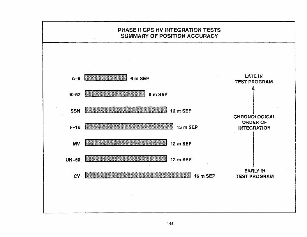
MV
PHASE II GPS HV INTEGRATION TESTS SUMMARY OF POSITION ACCURACY
145
LATE IN TEST PROGRAM
CHRONOLOGICAL ORDER OF
INTEGRATION
EARLY IN TEST PROGRAM
Operational usability tests of the 1-channel M/V UE sets were conducted by the Navy in a marine environment aboard the Sea Fox boat. To avoid duplication with Army tests of the same equipment, only Navy-unique scenarios were conducted. The main objective was to determine GPS mission enhancement. In its stand-alone configuration, the set met all planned objectives, providing better than 12-meter accuracy in all environments and greatly enhancing those missions for which it was test~d.
Army Phase II IOT&E was conducted in two subphases. The developmental testing (DT-llA) was completed on the 2-channel and 1-channel UE sets. Both UE sets from each contractor were deemed capable of meeting the technical performance criteria established for the fully operational system. The operational testing (OT-II) was conducted with the 1-channel UE sets in various M/V configurations and the 2-channel UE sets installed in the UH-60. Major test issues addressed during OT-II included mission performance, EMl/EMC, vulnerability, and reliability/availability/maintainability (RAM). OT-II also yielded additional data relative to logistics, training, doctrine, deployment, human factors, and safety. Some of the most critical results to come from these tests were an observed mean time between operational mission failure (MTBOMF) of 45 hours for the Rockwell-Collins M/V UE set and 108 hours for the Rockwell-Collins UH-60 UE set. The MTBOMF values for the two Magnavox UE sets were similarly low.
6.2.2.2 Weapon Delivery Results
Weapon delivery was significantly enhanced by integrating GPS with the aircraft's bomb/nav systems. The accompanying figure shows the bombing results for a series of low-level, passive, ballistic (gravity) weapon delivery sorties. For each aircraft, these are the unedited results (all drops shown) for the particular test sequence. For comparison, the radar baseline (active emission) accuracies are also shown.
146
These weapon delivery tests were generally accomplished by using the 1-channel M/V UE sets to determine the exact coordinates of a survey marker located at random on the test range. The coordinates of the marker were then relayed to the aircraft as its intended target. This was much the same way that a GPS-guided FAC would radio up target coordinates to a close air support aircraft.
In addition to these low-level bombing tests, many other weapon delivery applications were tested. These included highaltitude drops, high-drag munitions, and toss bombing applications. One of the most notable weapon delivery enhancements was found in the area of guided (smart) munitions where target handoff and acquisition were greatly improved using the very accurate position data from GPS.
6.2.2.3 Phase II Summary
Phase II revalidated GPS technology, feasibility, and the significant enhancements the system offers to military users. It also allowed selecting one contractor's UE set designs over another based on the head-to-head competition. The Phase II testing ended, however, with a number of deficiencies still present in the winning contractor's equipment. Among the conclusions reached from the analysis of these deficiencies were: the UE set software did not fully mature during Phase II; the reliability was not satisfactory; the technical data, TMs, and SE were inadequate to operate and support the UE sets (although they did not prevent the completion of testing); and there were varying degrees of success with the Phase II UE/HV integrations. As a result of these findings-in particular, the low reliability-several hardware and software improvements were identified, along with repackaging requirements, for inclusion in the LRIP effort and for retest during Phase Ill.

GPS LOW-LEVEL BALLISTIC WEAPON DELIVERY
B-52G 1200/6500 AGL*
18 RELEASES
• • • •• • • • .... ..
•• •
F-16A 1500 AGL*
46 RELEASES
I : •
.~, •
AGL* = ABOVE GROUND LEVEL (FT)
147
A-6E 1000 AGL*
24 RELEASES

6.3 PHASE Ill
6.3.1 Phase Ill Test Activities
The GPS UE Phase Ill LRIP effort began in 1985 and will continue through 1992. Rockwell-Collins was the winner of the Phase II competition and is the Phase Ill LRIP contractor.
The MILSPEC UE set configurations selected for production during Phase Ill differ somewhat from those originally developed during Phase II. The most visible differences are the result of repackaging decisions, but there are also many internal hardware and software improvements to remedy deficiencies found by the Phase II testing. The F-16/8-52 UE set developed in Phase II stayed basically the same and is now the RCVR-3A UE set. The A-6E UE set was dropped from the Phase Ill production because it was found to be more cost effective to upgrade existing HV bomb/nav computers to take advantage of GPS accuracies than to continue with unique airborne UE set configurations. The separately configured submarine and aircraft carrier UE sets from Phase II were combined to make the RCVR-3S UE set (i.e., the 5-channel receiver and atomic clock interfaces from the SSN set plus the external antenna, dual CDU, and digital interface capabilities from the CV set). This minimized the logistics costs by having a single shipborne configuration to support. The UH-60 and M/V UE sets from Phase II changed little to become the RCVR-UH and RPU-1 UE sets of Phase Ill. The two new RCVR configurations of Phase Ill came about in two different ways: the genesis of the RCVR-OH was much like combining the 2-channel RCVR-UH with the MIL-STD-1553 interface from the RCVR-3A, whereas the RCVR-C4 was a nearly new development in order to respond to HY-unique requirements.
Because of the changes in the Phase Ill UE sets, a major retest effort was undertaken on the redesigned equipment. To permit the collection of sufficient data to demonstrate reliability growth, a large part of the testing in Phase Ill was (and continues
148
to be) dedicated to verifying reliability-related design improvements. The Phase Ill test program is being conducted in accordance with an integrated multiservice test and evaluation master plan coordinated through each of the military services.
There are two types of testing in Phase Ill. The first was continued DT&E which consisted of in-plant, HV SIL, modification center, specialized Government laboratory, and field testing. Unlike Phase I and II, the in-plant testing was focused on an intensive test, analyze, and fix (T AAF) program to ensure the adequacy of the Phase II problem fixes and technology improvements in the Phase Ill pre-production equipment before it left the factory. Field DT&E was done with operational HVs using production integrations. The Phase Ill DT&E program managed by the GPS JPO, began in 1987 and was completed in 1989. The results are described in paragraph 6.3.2.
The second type of Phase Ill testing is operational test and evaluation (OT&E). This includes both the follow-on OT&E (FOT &E) for those items initially covered during Phase II as well as IOT&E for the new items developed during Phase Ill. As during Phase II, the RTOs for Air Force, Navy, and Army OT&E are AFOTEC, OPTEVFOR, and OPTEC. The scope of the Phase Ill OT&E effort is illustrated by the accompanying table. It will be completed in time for the Milestone 1118 full-rate production decision. FOT&E after Milestone 1118 may be continued by the individual services as required.
The NDI UE sets were not incorporated into the Phase Ill program. Instead, they are subject to their own individualized evaluation programs since it is not appropriate to test them against the MILSPEC requirements. The scope of these evaluation programs has been to verify the equipment performs as claimed by the manufacturer and will satisfy the intended military mission.
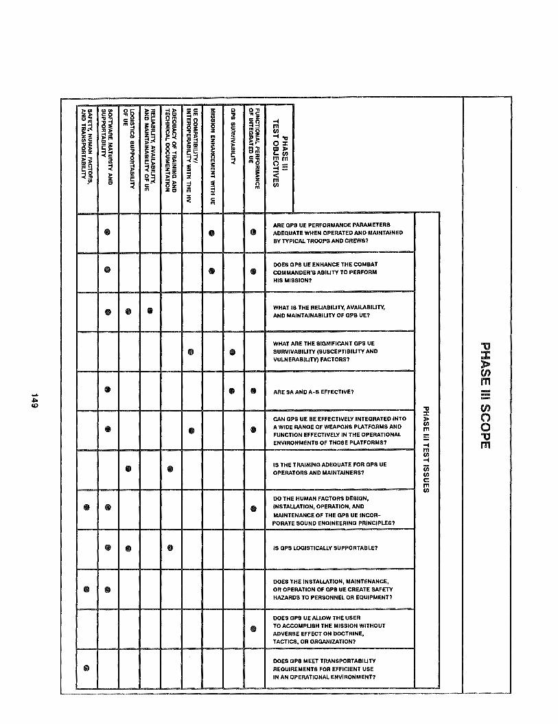
~~ ~~ ~8 ~ill nll!i -c II: c:> O"n :!im i ;J .,,c
C"n
~i c~ Om
mg -Z
j~ c- :c 0 zo .., m~ ~!!! zc ~II: 0 Ill -4 -4 m
- )> z c a~ (/)
z :c ;;: :ll ~ z c: ~Q ril~ m ~ .., .,, 11>C °' m ;;:.~ ~::l z ~~ ;H: -!I: Ill
§~ ~ ;; 0 ::c c: )> c z~ °' !!! °' m"!I
E~ :llZ ~ C! "!I - c: z E cm ;;: ..,, ~ ~~ !E ~ c: ~ 0 c:ll
~ ES: ~--- m ~ m~ mm °' )> :ll Ii: 0--o ;;: ~!!! mz
~ :ll c: -4 z- m .., ::: ~g ~ °' 0 c: ;;:~ z Ii: < E :i: -4 ~ ·°' ... ~ ::l )>
~ m c ~ -4 0 (/) c Oz :i: m Zc m m
:i: :i: c < m
ARE OPS UE PERFORMANCE PARAMETERS
• I I I I le • ADEQUATE WHEN OPERATED AND MAINTAINED
BY TYPICAL TROOPS AND CREWS?
• I I I I le I le I DOES OPS UE ENHANCE THE COMBAT
COMMANDER'S ABILITY TO PERFORM
HIS MISSION?
• , . I • I I I I I I WHAT IS THE RELIABILITY, AVAILABILITY,
AND MAINTAINABILITY OF OPS UE?
WHAT ARE THE SIGNIFICANT OPS UE
I I I "'CJ • I I• I I SURVIVABILITY (SUSCEPTIBILITY AND :c VULNERABILITY) FACTORS? )>
"' m .....
I I 1· I I I I I I • I • I ARE SA AND A·S EFFECTIVE? --.J:> -<O .,, "' ::c (") CAN OPS UE BE EFFECTIVELY INTEGRATED INTO >
• I I I '• I I I • I A WIDE RANGE OF WEAPONS PLATFORMS AND (/) 0 m
FUNCTION EFFECTIVELY IN THE OPERATIONAL "'CJ -ENVIRONMENTS OF THOSE PLATFORMS? .., m m (/)
I ..,
• I le I I I I I IS THE TRAINING ADEQUATE FOR OPS UE iii OPERATORS AND MAINTAINERS? (/)
c: m (/)
DO THE HUMAN FACTORS DESIGN,
• I • I I I I I I '• I INSTALLATION, OPERATION, AND
MAINTENANCE OF THE OPS UE INCOR-
I PORATE SOUND ENGINEERING PRINCIPLES?
• I. I IS OPS LOGISTICALLY SUPPORTABLE?
DOES THE INSTAl.LATION, MAINTENANCE,
• ,. I OR OPERATION OF OPS UE CREATE SAFETY
HAZARDS TO PERSONNEL OR EQUIPMENT?
DOES OPS UE Al.l.DW THE USER
• I TO ACCOMPLISH THE MISSION WITHOUT
ADVERSE EFFECT ON DOCTRINE,
TACTICS, OR ORGANIZATION?
DOES OPS MEET TRANSPORTABILITY • I I I I I I I I I REQUIREMENTS FOR EFFICIENT USE
IN AN OPERATIONAL ENVIRONMENT?
6.3.2 Phase Ill DT&E Results
The primary goals of Phase Ill DT&E were to evaluate the technical characteristics of the equipment, ensure compliance with the specifications, and verify the correction of Phase II deficiencies. Towards these goals, a set of eight specific DT&E objectives were developed:
1. Measure functional performance of the equipment to verify specification compliance.
2. Validate the LRIP contractor correction of Phase II deficiencies.
3. Verify GPS UE compatibility, integration, and interoperability with the HV and operating environment.
4. Gather reliability data to identify design/parts deficiencies and verify the contractual reliability specifications by projecting demonstrated results to system maturity.
5. Verify the ability of the UE sets to be maintained using TMs, BIT /BITE, and SE.
6. Gather data to validate the TMs.
7. Verify physical design requirements of the UE sets with respect to nuclear, biological, and chemical (NBC) contamination.
8. Measure UE performance under the specified jamming conditions and evaluate compliance.
Within each of these specific DT&E objectives, there were many individual test criteria for each major MILSPEC equipment item tested. For example, every one of the deficiencies identified in Phase II was a criterion for evaluation under DT&E objective 2.
150
Due to the detailed technical nature of several Phase Ill DT&E objectives, much of the testing was accomplished by specialized government laboratories. For the field test portion, specialized HVs were also used in the earfy part of the program. They included a rocket sled for high-dynamic testing of the RCVR-3A and an instrumented bus for testing of the RCVR-3S on shore. The formal field tests were all done with the operational HVs using production integrations. The HVs used for RCVR-3A testing were the F-16 and SH-608 aircraft. The HVs for the RCVR-3S were the CG-28 and FFG-20 ships along with the SSN-665 submarine. The RCVR-UH was tested on the UH-60. The RPU-1 was tested in the manpack configuration as a stand-alone unit and in the vehicle configuration on the HMMWV, the CUCV, and the Sea Fox boat. The ITS units were tested by maintenance personnel in an operational setting.
Easily the most significant result from Phase Ill DT&E was the successful correction of most Phase II deficiencies related to UE set reliability (a combination of objectives 2 and 4). These reliability deficiencies were, after all, the main reason that Phase Ill started as an lRIP effort instead of going directly into full-rate production. For the RCVR-3A UE set, all of the Phase II deficiencies against it (both those related to reliability and otherwise) were fixed and verified during DT&E. Correspondingly, none of the RCVR-3A UE sets had an operational mission failure during a total of 375.4 hours of accumulated flight test time. likewise, all of the RCVR-3S UE set deficiencies were closed out and the tested units suffered only 9 failures in 10, 191 operating hours to give an MTBOMF of 1, 132 hours-already above its mature specification value. The demonstrated reliability of the ITS units were also well over the required 1,000-hour MTBOMF.
Correcting the Phase II deficiencies against the RCVR-UH and RPU-1 UE sets also improved their reliability over the Phase II figures, but not enough. During Phase Ill DT&E, the RCVR-UH UE sets were only able to achieve an MTBOMF of 128 hours while the RPU-1 UE sets demonstrated 79 hours MTBOMF. Subsequent analysis found most of these operational mission failures were due
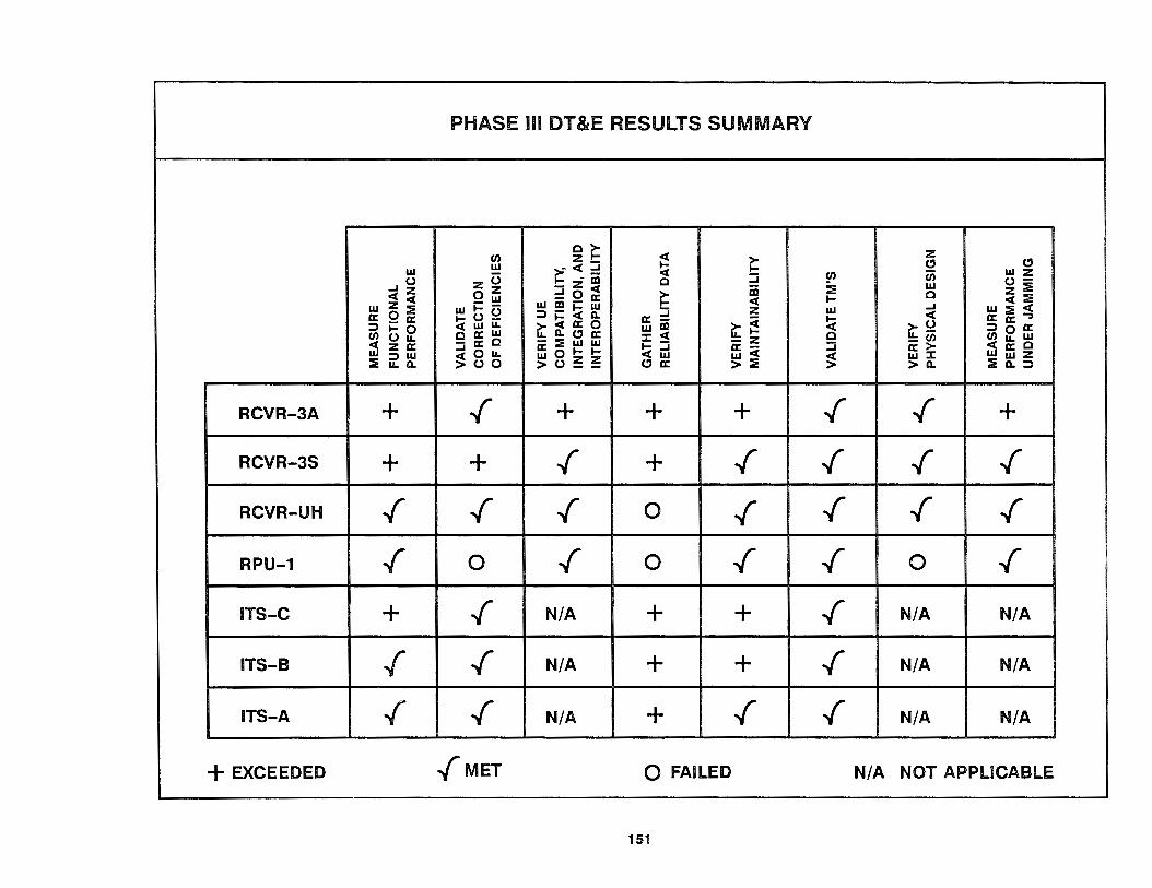
PHASE m DT&E RESULTS SUMMARY
(/) c~
~ ~ z :z_ CJ CJ UJ ~- < = UJ
z C3 :i (/) u; UJ z ..J () - al c () -- z < :: UJ z :: < :i oz = 0 a: ~
al c - UJ < I- < ::
UJ z :: UJ I- C3 UJ al i= UJ a: ;;! z w ..J w :: <
a: Q a: I- () - =>i=<ll. rt ~ !:i < a: a: ..,
:::> I- 0 < w II.. rt < a: 0 w al rt ~ :::> 0 a: (/) () II.. c a: w 11. CJ a: ::c < c (/) II.. w - a: c - :: w w -z - (/) ;'.5 z a: I- - a: - :i a: > < a: c ~ 0 II.. a:Ql-1- < iii :::il :::> w ~ () ~ ~ w< ~ w ::c Ww:Z
II.. 11. > () 0 CJ a: > :: > 11. :::t Q. :::>
RCVR-3A + ~ + + + ~ ~ +
RCVR-3S + + ~ + ~ ~ ~ ~
RCVR-UH ~ ~ ~ 0 ~ ~ ~ ~
RPU-1 ~ 0 ~ 0 ~ ~ 0 ~
ITS-C + ~ N/A + + ~ N/A N/A
ITS-B /" ~ N/A + + ~ N/A N/A
ITS-A ~ ~ N/A + ~ ~ N/A N/A
+EXCEEDED ~MET 0 FAILED N/A NOT APPLICABLE
151

primarily to a small number of residual software bugs that reoccurred repeatedly under certain field test conditions. These bugs have been fixed, and the reliability of these UE sets is under retest during Phase Ill OT&E.
The functional performance testing conducted during Phase Ill DT&E (objective 1) has generally continued to show the same better-than-specification performance found during Phase II. In testing against the required 16 meter SEP accuracy, RGYR-3A UE sets achieved 11 to 15 meter SEP, RCYR-3S UE sets achieved 5.5 meters SEP, RCYR-UH UE sets achieved 10 to 12 meter SEP, and RPU-1 UE sets achieved 9 to 12 meter SEP. The same type of better-than-specification performance was found for other technical criteria such as the UTC time accuracy and REACjTTFF. One area in which all tested UE sets fell short was in their velocity accuracy under high dynamics ("high" being relative to the individual requirements for each type of UE set). These velocity determination problems are being addressed in Phase Ill OT&E. The ITSs were also found to perform well, with only a few minor exceptions found in the ITS-B and ITS-A
As noted earlier, the Phase II deficiencies related to reliability were tested successfully. The same was true for almost all other Phase II deficiencies (objective 2). The only notable exceptions occurred in the case of the RPU-1 UE sets where some problems remain in the environmental, EMC, and NBC contamination areas. However, none of these problems were considered severe enough to impact the start of Phase Ill OT&E.
For the DT&E objective of verifying GPS UE compatibility, integration, and interoperability (objective 3), the HY integration concepts and designs were as much the focus of the test as the particular UE sets. The results for the RCYR-3A UE set integrated into both the F-16 and the SH-60B were very good. The accompanying figure shows the results from a representative test flight with the F-16. The particular HY integration concept here is for the GPS data to be used by the F-16's fire control computer (FCC) in conjunction with data from the INS to develop a "best estimate"
152
on-board position solution. As can be seen, the FCC solution follows the GPS solution very well. Another aspect of this particular integration concept can be seen in the long-term drift of the INS. Since this particular design called for the INS to be periodically reset ratherthan calibrated using data from the UE set, the drift-reset sawtooth behavior of the INS shown here is a characteristic of this type of integration. Similar results were also found with the RCYR-3S in integrated configurations with various shipboard INSs. Resets and at-sea calibrations of the INSs were also performed successfully. Other than the RPU-1 problems noted earlier in the EMC area (which also affected its operation in vehicles), only minor integration problems were found during DT &E. These problems have been fixed, and are under retest during OT&E.
The Phase Ill DT&E results for maintainability (objective 5) were very favorable, with all items either meeting or exceeding requirements. The TM results (objective 6) were also positive, with every TM being validated (except for the depot-level TMs, which were still in development). The results of the physical design requirement verifications (objective 7) were generally acceptable except that antennas were rated marginal, and the already known RPU-1 NBC deficiency. The UE set results under jamming (objective 8) were within specification whenever a FRPA system was used. With both a CRPA system and INS aiding, the RCYR-3A UE set achieved an outstanding robustness against the jamming threat.
Based on the overall results from Phase Ill DT&E, the various equipment items tested were each certified by the GPS JPO as ready to proceed on to OT&E between mid-1989 and early 1990. These certifications included the two 5-channel UE sets (the RCYR-3A and RCYR-3S), the 2-channel UE set for helicopter use (the RCYR-UH), and the 1-channel UE set (the RPU-1). Also certified for inclusion in OT&E were the three ITS units (the ITS-C, ITS-B, and ITS-A).

-en a:
a.. w w I-ow :? -
F-16 FLIGHT TEST DATA PORTRAYAL
15 NOVEMBER 1988 GPS AVERAGE HORIZONTAL ERROR (CEP)
GPS AVERAGE VERTICAL ERROR (LEP)
70
60
50
40
30
20
10
0
15:30 15:40
11 FIRE CONTROL + INS
15:50 16:00
+ GPS
153

6.3.3 Phase Ill OT&E Results
Phase Ill OT&E for the various UE sets and ITS units began soon after each equipment item was certified ready by the GPS JPO. The two 5-channel sets were the first to start OT&E in mid-1989 along with the ITS-C. Then the 1-channel UE set was sequentially certified for Air Force, Navy, and Army testing along with the ITS-A. The final JPO certifications were for the 2-channel UH-60 set and the ITS-B in early 1990. UE set configurations and HV integrations evaluated during OT&E were basically the same as DT&E, but with several hardware and software updates incorporated to resolve previously identified problems.
The Phase Ill OT&E programs initially ran from three to six months on each HV. They were independently conducted by the same test and evaluation organizations that performed Phase II IOT&E. Although conducted independently, a great deal of multiservice coordination between the RTOs and the JPO occurred to minimize the duplication of scenarios and to maximize test data collected across a broad spectrum of operational missions.
Air Force testing of the RCVR-3A UE set in the F-16 and the RPU-1 UE set was conducted by AFOTEC. The F-16 testing began with operational pilots verifying GPS enhancement of the F-16's navigation capabilities and in-flight INS alignment. Combat control teams tested the RPU-1 performance by parachuting from an aircraft and using the set to guide them to a predetermined location where they used it successfully to lay out an austere runway.
Navy tests of the RCVR-3S UE set aboard a CG and a SSN, the RCVR-3A UE set in the SH-60B, and the RPU-1 UE set on a Sea Fox were conducted by OPTEVFOR. Mission scenarios for the RCVR-3S included all operations conducted by the HVs while on routine deployment (e.g., open ocean transit, harbor piloting, weapon targeting) in the normal EMI environment. The SH-60B testing also addressed UE compatibility in routine HV operations. The Sea Fox scenarios focused on missions such as reconnaissance, infiltration, and amphibious landings.
154
Army OT&E for the RPU-1 UE set by OPTEC concentrated on Army-unique tactical scenarios. These included: Signal Battalion troops using the set in M/V configurations to navigate to preplanned locations for positioning of communication equipment and relays; Artillery Battalion troops updating position and azimuth determining system (PADS) equipment and supporting field artillery and air defense (Patriot) site selection; Rangers and Special Forces surveying sites for Trailblazer, Teampack, and other intelligence collection assets; and Army watercraft navigation. The tests of the RCVR-UH UE set aboard the UH-60 at Ft. Huachuca, ft:Z.. and Ft. Lewis, WA were the last OT&E program completed. These tests exercised the fully integrated capabilities of the UH-60 helicopter in a wide variety of short- and long-range tactical and support missions. Corridor, moving waypoint, linkup, and emergency instrument approach missions were validated.
The results from Phase Ill OT&E clearly demonstrated satisfactory GPS operational effectiveness. This finding covers the criteria of functional performance, survivability, mission enhancement, and UE compatibility /interoperability. These results, however, did not demonstrate satisfactory GPS operational suitability. As before, the RPU-1 and RCVR-UH UE sets failed to meet their reliability requirements. There were also certain suitability issues that were not fully evaluated on the RCVR-3A UE set.
In response to the unsatisfactory operational suitability finding from OT&E, another T AAF effort was conducted on the UE sets through the end of 1990. An additional Phase Ill period of extended operational testing (EOT) began at the start of 1991 to verify correction of the operational suitability issues. This EOT is currently going on with a scheduled completion date before Milestone lllB. To streamline the evaluations, the Air Force is only testing RCVR-3A UE sets while the Navy tests the RCVR-3S UE sets and the Army tests the RPU-1 and RCVR-UH UE sets. To maximize the number of flight test hours, the scope of the Air Force EOT has been expanded to include the B-52, MH-53, and RC-135, as well as the F-16. The scope of Navy testing likewise now includes a CV, an FFG, and an SSN.

I~~'·, --:_·~- \
PHASE m OT&E HVs
155

6.4 OTHER TESTING
in addition to the formal Phase 1/11/111 UE set test programs, a number of other tests have demonstrated the robustness of the system, expanded the range of potential applications, or showed the practical utility of GPS.
In order to check the interoperability of the Block II SVs with the existing OCS and UE sets prior to the first launch (to prevent a "Hubble Telescope" mistake), a series of system level interface compatibility (SLIC) tests were conducted at Cape Canaveral AFS with a Block II SV powered up and transmitting while still on the ground. For these tests, a Block II SV was connected to a hemispherical broadcast antenna and was sent a data upload from the OCS to make it behave as if it were in a geosynchronous orbit located over Cape Canaveral. The various types of UE sets (MILSPEC, NDI, and civilian) then attempted to track its L-band signals, as well as those from on-orbit Block I SVs, for interface compatibility evaluation. An added complexity of the SLIC tests was that they were the first opportunities to test many SA and A-S features end-to-end with the operational equipment. Even with this unusual test setup, the system interfaces worked exactly as designed and the tests were successfully completed. Based upon the SLIC test results, the way was cleared for the first Block II SV launch in February 1989.
For certifying GPS as a primary instrument for en route and approach-to-landing navigation, the Air Force Instrument Flight Center (IFC) is developing the terminal instrument procedures (TERPS), aircrew procedures, and charting requirements (e.g., FLIP products) for DoD use of GPS in the NAS. The baseline plan for using GPS in the NAS is to use it to emulate existing radionavigation systems (TACAN, VOR/DME, etc.). To test this emulation capability along with the newly developed procedures and charts, the IFC is integrating the RCVR-3A and the DAC with the existing flight instruments on a pair of T-39 aircraft. The first part of the T-39 testing has already demonstrated GPS capabilities to emulate ground-based systems at YPG. The second part of the testing will examine potential improvements in instrument procedure design and will expand to cover several NAS locations
156
through 1992. The results of this effort may flow back into the ongoing negotiations between civilian users, the DoD, the DoT, and ICAO, ultimately leading to the approval of GPS for general aviation use as a sole-means-of-navigation system.
In actual military applications, GPS played only a minor role in operations of the 1980s. The small number of available UE sets plus the short satellite coverage windows limited GPS use in operations such as those in Grenada and Panama to relatively low levels. However, the rapidly growing number of UE sets now in the DoD inventory (particularly SLGRs) and the tremendous increase in satellite coverage afforded by the Block II SV launches are combining to make the 1990s the decade of GPS. Nowhere has this been demonstrated more forcefully than the recent conflict in Southwest Asia.
During Operations Desert Shield and Desert Storm in 1990-1991, GPS proved its practical utility in a major way. Almost every available UE set was sent over to support the troops where GPS was called ''the single most important piece of new gear in the desert". Although this was not a true test, it is hard to imagine a more realistic scenario in which to demonstrate/validate the military use of GPS. The system found its way into nearly every operation conducted by allied forces. Some of the more interesting unclassified ground applications were:
• Locating and patrolling international borders that are literally no more than lines in the sand.
• Establishing and returning to clandestine refuel and rearm supply points.
• Noting the coordinates of a vehicle breakdown and later using GPS to return to those same coordinates to retrieve the vehicle and the troops left to guard it.
• Preventing supply trucks from getting lost either because drivers cannot read road signs written in Arabic or because there simply are no roads.

GPS RWY 18 COMPLEX (E) V\MAU~CCN 1llD.O 314.0 lMllMA 1CW!ll t21.2 1:41.0 Ofl>CCN 121.1 221.4
FOR TEST USE ONLY
HOUIA WP
3100
NOT FOR PUBLICATION OR OTHER USE
OTHER "TESTING"
LAGUNA AAP (lQP) ~·l'AOVNJOAOLNt. AA1ZCNA
EL.EV 422
N3:19 027 w11..- 20.T
I UIFI.. Awr 11 ·31
171" ' .. ® TDZE«is
GPS RWY 18 COMPLEX (E) l2"52'N·l1••2•w LAGUNAAAF(LGF) YUMA PAOV1NG GROUND. ARIZONA
157

7.0 SUMMARY
From the foregoing system overview, it should be recognized that the Navstar Global Positioning System has evolved into a highly accurate (16-meter, 3-D position accuracy), worldwide, allweather navigation system applicable to the needs of both the military and civil communities. The results from Phase I verified that the system operated as conceptualized and that the accuracy goals established were achievable in a variety of HVs_:_in the air, on land, and at sea. Phase II of the program further substantiated this verification process by ensuring that the system operates successfully in a military environment under various missionoriented conditions. Phase Ill is producing a family of RCVR and other LRUs that can be configured by a prospective user into a UE set that fits his/her particular application.
Rockwell-Collins (LRIP /CLAP), SCI Technology /E-Systems (CLAP), and other manufacturers are now producing a family of MILSPEC LRUs in limited quantities. Deliveries to the participating services and agencies began in October 1988. Full-scale production will begin after the Milestone 1118.
158
In addition to the MILSPEC LAU production, NDI efforts currently under way will provide alternatives in GPS UE set technology, design, and capabilities. This multifaceted approach to GPS UE development was established to meet the broad range of user requirements as well as achieving low life-cycle and maintenance support costs.
Consequently, GPS has been selected by the U.S. Government to supplement and/or replace other radionavigation systems currently in use. To support this selection, the DoD has determined that all GPS UE-equipped military aircraft will use the PPS for flight in the NAS and will require its use in any other direct combat support operations. Furthermore, the DoD and DoT have established a policy to guarantee civil access to the GPS. The SPS users will be able to determine their positions to within 100 meters (2 drms) once the system becomes operational. Selected civil users may also qualify to get PPS access to full system accuracy. This overall DoD policy on civil access was established to balance the national security needs against the practical requirements of civil aviation, maritime, and ground-based users.

GPS - FOR TODAY AND TOMORROW
GPS IS THE ONLY NAVIGATION SYSTEM THAT WILL FULFILL ALL OF THESE AND OTHER USER NEEDS
CLOSE SUPPORT, COMMON GRID COORDINATION
ENROUTE NAUTICAL AND AERONAUTICAL NAVIGATION
TIME TRANSFER
MINE LAYING AND SENSOR DELIVERY
RANGE INSTRUMENTATION
PHOTOMAPPING, PHOTOTARGETING,
COORDINATE BOMBING
159
PRECISE RENDEZVOUS, REFUELING, RESCUE, RESUPPLY
ANTI-SUBMARINE WARFARE
HARBOR CONTROL
All WEATHER LANDING APPROACH AIDS
RIVERINE AND SMALL CRAFT OPERATIONS
GEODESY AND SURVEY
VTOL, STOL, AND HELICOPTER TAKEOFF, LANDING, AND CRUISE OPERATIONS

8.0 ABBREVIATIONS AND ACRONYMS
AE Antenna Electronics CHAALS Coherent High-Accuracy Airborne Location AFB Air Force Base System AFLC Air Force Logistics Command CLRP Continuing Low-Rate Production AFOTEC Air Force Operational Test and Evaluation Center CO MS EC Communications Security AFS Air Force Station CRPA Controlled Reception Pattern Antenna AFSC Air Force Systems Command CSE Common Support Equipment AFSPACECOM Air Force Space Command csoc Consolidated Space Operations Center AHRS Attitude and Heading Reference System cucv Commercial Utility Cargo Vehicle ALC Air Logistics Center CV Cryptographic Variable; AM Amplitude Modulation Designator for an Aircraft Carrier AME Ancillary Mission Equipment CVw Weekly Cryptographic Variable ANM Automated Notice to Mariner ANVIS Aviator's Night Vision Imaging System 2-D Two-Dimensional AOL Advanced Quick-Look 3-D Three-Dimensional A-S Anti-Spoofing DAB Defense Acquisition Board ASD Aeronautical Systems Division (AFSC) DAC Digital-to-Analog Converter ATE Automatic Test Equipment DAS Data Analysis Station ATR Austin Trumbull Radio dBW Decibels with Respect to One Watt ATR Air Transport Racking DGPS Differential GPS AUTONAV Autonomously Navigate; Autonomous Navigation OMA Defense Mapping Agency AVIM Aviation Intermediate Maintenance DME Distance Measuring Equipment AVUM Aviation Unit Maintenance DNSS Defense Navigation Satellite System
DoD Department of Defense Baro Barometric (Altimeter) DOP Dilution of Precision BIT Built-In Test DoT Department of Transportation BITE Built-In Test Equipment DPM Deputy Program Manager BRA-34 A type of submarine antenna DR Delta Range BRG Bearing drms Distance Root Mean Square
2 drms Twice the Distance Root Mean Square C/A-code Coarse Acquisition Code DRVS Doppler Radar Velocity Sensor CADC Central Air Data Computer DSARC Defense Systems Acquisition Review Council CB Clock Bias OT Developmental Testing CD Clock Drift DT&E Developmental Test and Evaluation CDMA Code Division Multiple Access DTK Desired Track Angle CDU Control Display Unit CEP Circular Error Probable EDOP East DOP CGSS Composite Global Sample Space EFIS Electronic Flight Instrumentation System
160

EMC Electromagnetic Compatibility IF Intermediate Frequency EMI Electromagnetic Interference IFC Instrument Flight Center (Air Force) EMP Electromagnetic Pulse IFTE Integrated Family of Test Equipment EOT Extended Operational Testing ILS Instrument Landing System
IMU Inertial Measurement Unit FAC Forward Air Controller INIT Initialize FAFB Falcon AFB INS Inertial Navigation System FCC Fire Control Computer IOC Initial Operational Capability FFG Designator for a Fast Frigate IOT&E Initial Operational Test and Evaluation FLIP Flight Information Publication ISF Integration Support Facility FM Frequency Modulation ITS Intermediate Test Set FOC Full Operational Capability FOM Figure Of Merit J/S Jammer-to-Signal FOT&E Follow-on Operational Test and Evaluation JPO Joint Program Office FRP Federal Radionavigation Plan JRMB Joint Requirements Management Board FRPA Fixed Reception Pattern Antenna JSSMO Joint Service System Management Office FRPA-GP FRPA Ground Plane JTIDS Joint Tactical Information Distribution System
GA Ground Antenna L1 Link 1 (L-Band Signal) GOOP Geometric DOP L2 Link 2 (L-Band Signal) GLONASS Global Navigation Satellite System LAAFB Los Angeles AFB GPS Global Positioning System L-Band Traditional Designator for 1000-2000 MHz Radar GPSIC GPS Information Center (U.S. Coast Guard) LCAC Landing Craft, Air Cushioned GS Ground Speed LO Low-Dynamic GUV Group Unique Variable LEP Linear Error Probable
Loran A radionavigation system HD High-Dynamic LPTS Low-Power Time Source HOOP Horizontal DOP LRIP Low-Rate Initial Production HDUE High-Dynamics UE LRU Line Replaceable Unit HMMWV High-Mobility Multipurpose Wheeled Vehicle HSI Horizontal Situation Indicator m Meters HV Host Vehicle m/sec Meters per Second HVIA HV Interface Adaptors MAGR Miniature Airborne GPS Receiver HWL Height-Width-Length MCS Master Control Station Hz Hertz ~8T Mean Corrective Maintenance Time
Medium-Dynamic ICAO International Civil Aviation Organization MGRS Military Grid Reference System ICD Interface Control Document MILSPEC Military Specification ICS Initial Control Segment MLS Microwave Landing System ICS Interim Contractor Support MLV Medium Launch Vehicle
161
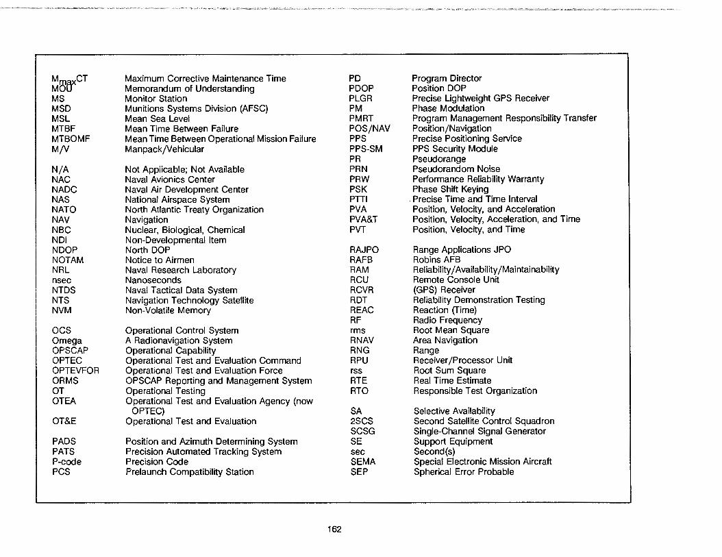
~l1}{fCT Maximum Corrective Maintenance Time PD Program Director Memorandum of Understanding POOP Position DOP
MS Monitor Station PLGR Precise Lightweight GPS Receiver MSD Munitions Systems Division (AFSC) PM Phase Modulation MSL Mean Sea Level PMRT Program Management Responsibility Transfer MTBF Mean Time Between Failure POS/NAV Position/Navigation MTBOMF Mean Time Between Operational Mission Failure PPS Precise Positioning Service M/V ManpackjVehicular PPS-SM PPS Security Module
PR Pseudorange N/A Not Applicable; Not Available PRN Pseudorandom Noise NAC Naval Avionics Center PRW Performance Reliability Warranty NADC Naval Air Development Center PSK Phase Shift Keying NAS National Airspace System PTTI . Precise Time and Time Interval NATO North Atlantic Treaty Organization PVA Position, Velocity, and Acceleration NAV Navigation PVA&T Position, Velocity, Acceleration, and Time NBC Nuclear, Biological, Chemical PVT Position, Velocity, and Time NDI Non-Developmental Item NDOP North DOP RAJ PO Range Applications JPO NOT AM Notice to Airmen RAFB Robins AFB NRL Naval Research Laboratory RAM Reliability/ Availability /Maintainability nsec Nanoseconds RCU Remote Console Unit NTDS Naval Tactical Data System RCVR (GPS) Receiver NTS Navigation Technology Satellite ROT Reliability Demonstration Testing NVM Non-Volatile Memory REAC Reaction (fime)
RF Radio Frequency ocs Operational Control System rms Root Mean Square Omega A Radionavigation System RNAV Area Navigation OPS CAP Operational Capability RNG Range OPTEC Operational Test and Evaluation Command RPU Receiver /Processor Unit OPTEVFOR Operational Test and Evaluation Force rss Root Sum Square ORMS OPSCAP Reporting and Management System RTE Real Time Estimate OT Operational Testing RTO Responsible Test Organization OTEA Operational Test and Evaluation Agency (now
OPTEC) SA Selective Availability OT&E Operational Test and Evaluation 2SCS Second Satellite Control Squadron
SCSG Single-Channel Signal Generator PADS Position and Azimuth Determining System SE Support Equipment PATS Precision Automated Tracking System sec Second(s) P-code Precision Code SEMA Special Electronic Mission Aircraft PCS Prelaunch Compatibility Station SEP Spherical Error Probable
162
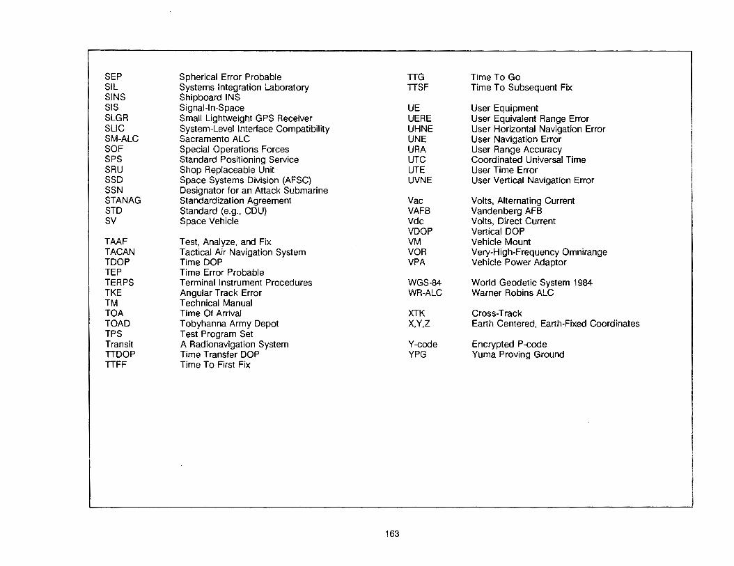
SEP Spherical Error Probable TIG Time To Go SIL Systems Integration Laboratory TISF Time To Subsequent Fix SINS Shipboard INS SIS Signal-In-Space UE User Equipment SLGR Small Lightweight GPS Receiver UERE User Equivalent Range Error sue System-Level Interface Compatibility UHNE User Horizontal Navigation Error SM-ALC Sacramento ALC UNE User Navigation Error SOF Special Operations Forces URA User Range Accuracy SPS Standard Positioning SeNice UTC Coordinated Universal Time SRU Shop Replaceable Unit UTE User Time Error SSD Space Systems Division (AFSC) UVNE User Vertical Navigation Error SSN Designator for an Attack Submarine STANAG Standardization Agreement Vac Volts, Alternating Current STD Standard (e.g., CDU) VAFB Vandenberg AFB SV Space Vehicle Vdc Volts, Direct Current
VDOP Vertical DOP TAAF Test, Analyze, and Fix VM Vehicle Mount TACAN Tactical Air Navigation System VOA Very-High-Frequency Omnirange TOOP Time DOP VPA Vehicle Power Adaptor TEP Time Error Probable TERPS Terminal Instrument Procedures WGS-84 World Geodetic System 1984 TKE Angular Track Error WR-ALC Warner Robins ALC TM Technical Manual TOA Time Of Arrival XTK Cross-Track TOAD Tobyhanna Army Depot X,Y,Z Earth Centered, Earth-Fixed Coordinates TPS Test Program Set Transit A Radionavigation System Y-code Encrypted P-code TIDOP Time Transfer DOP YPG Yuma Proving Ground TIFF Time To First Fix
163

9.0 INFORMATION DIRECTORY
Further details of GPS activities can be obtained from the following National Coordinators.
• --
AUSTRALIA Department of Defence Air Force Office OR NAV Russell Offices A-9-18 Canberra ACT 2600, Australia
DENMARK CHOO Denmark Attn: MM 109 PO 202 DK-2950, Vedbaek, Denmark
ITALY State Maggiore Aeronautlca Viale dell Unlverslta 4 00185 Rome, Italy
SPAIN Mlnlsterlo De Defensa DGAM Paseo De la Castellana, 109 28046 Madrid, Spain
= ~ ~
~ ~
BELGIUM MOD Belgium Air Force Staff/
Avionics Branch (VDT/B) Quartler Reine Elisabeth 1 Rue D'Evere 1140 Brussels, Belgium
FRANCE ST CAN 8 Boulevard Victor 75732 Paris, France
THE NETHERLANDS Office of Material Development Kalvermarkt 28 Postbus 20701 2500ES The Hague,
The Netherlands
UNITED KINGDOM MODUK PE (A D/A Radio 2) St. Giies Court 1-13 St. Giies High Street London WC2H BlD United Kingdom
164
• ~
CANADA National Defence Headquarters Attn: DCDS/DAR 3 101 Colonel By Drive Ottawa, Ontario K1 A OK2, Canada
FEDERAL REPUBLIC OF GERMANY GMOD Rue VI 3 Post'fach 1328 5300 Bonn, West Germany
NORWAY Hq Defence Command CAN DE OSLO Mil Oslo 1, Norway
UNITED STATES DoD and Allied Miiitary:
DASO (c3)/f&TC3 Pentagon 30174 Washington, DC 20301-3040
Clvll/Commerclal: Commanding Officer U.S. Coast Guard ONSCEN 7323 Telegraph Road Alexandria, VA 22310-3998
