gps surveying of estuarine sites and water level …. department of the interior u.s. geological...
TRANSCRIPT

U.S. DEPARTMENT OF THE INTERIOR
U.S. GEOLOGICAL SURVEY
GPS Surveying of Estuarine Sites and Water Level Gages in the Lower Suwannee River Watershed
by
Ellen A. Raabe, Nancy J. Marth, and Richard P. Stumpf
OPEN FILE REPORT 00-296
This report is preliminary and has not been reviewed for conformity with U.S. Geological Survey editorial standards.
U.S. Geological Survey, Center for Coastal Geology St. Petersburg, FL 33701

DISCLAIMER
This publication was prepared by an agency of the United States Government. Neither the United States Government nor any agency thereof, nor any of their employees, makes any warranty, expressed or implied, or assumes any legal responsibility for the accuracy, completeness, or usefulness of any information, apparatus, product, or process disclosed in the report, or represents that its use would not infringe privately owned rights. Reference therein to any specific commercial product, process, or service by trade name, trademark, manufacturer, or otherwise does not necessarily constitute or imply its endorsement, recommendation, or favoring by the United States Government or any agency thereof. Any views and opinions of authors expressed herein do not necessarily state or reflect those of the United States Government or any agency thereof.
11

CONTENTS
SUMMARY........................................................................................................................... 1
INTRODUCTION ...................................................................................................................1
BACKGROUND.....................................................................................................................3
METHODS...........................................................................................................................^SURVEY PLANNING AND FIELD LOGISTICS....................................................................4SURVEY EXECUTION......................................................................................................6POST-PROCESSING AND RESULTS..................................................................................8
DISCUSSION ........................................................................................................................9
REFERENCES ..................................................................................................................... 12
ACKNOWLEGDMENTS........................................................................................................ 12
APPENDIX 1....................................................................................................................... 13
APPENDIX 2.......................................................................................................................17
TABLES
TABLE 1. GPS OCCUPATION OF LOWER SUWANNEE SITES APRIL 20-21,1998.................. 6TABLE 2. GPS OCCUPATION OF LOWER SUWANNEE SITES APRIL 29-30,1998. .................1TABLE3. DGPS-DERIVEDORTHOMETRICHEIGHTS............................................................8TABLE 4. VECTOR LENGTH VARIATION FROM MULTIPLE OCCUPATIONS. .......................... 10TABLES. HORIZONTAL AND VERTICAL CONTROL ............................................................ 14TABLE 6. ORTHOMETRIC HEIGHT OF NAILS ...................................................................... 14TABLE 7. COMPARISON OF PUBLISHED AND DERIVED HEIGHTS ........................................ 17
IILLUSTRATIONS
FIGURE 1. LOCATION OF GPS SURVEY SITES. ....................................................................2FIGURE 2. BASE STATION AND PORTABLE ROVING ANTENNA. ............................................5FIGURES. ANGLER'S RESORT BENCHMARK. ...................................................................11FIGURE 4. LOCATION OF DUNN GPS 1997.......................................................................15FIGURE 5. LOCATION OF SURVEY NAILS AND DUNN GPS 1997........................................ 16
in

GPS Surveying of Estuarine Sites and Water Level Gages in the Lower Suwannee River Watershed
Ellen A. Raabe, Nancy J. Marth, and Richard P. Stumpf
Summary
Population increases in Florida are compelling water management district managers to evaluate the impact of freshwater withdrawal and drinking water supply projects on flood plain and down-river estuarine resources. In 1997 the Suwannee River Water Management District and the U.S. Geological Survey (USGS) undertook a study of Suwannee River discharge variations and the impact on the flood plain ecosystem in Levy and Dixie counties.
Elevation plays an important role in the frequency and duration of flooding in river and estuarine plant communities. Scientists conducted leveling surveys to determine elevations in their study areas. However, the vegetation monitoring transects in the Lower Suwannee River Refuge were difficult to access with traditional leveling methods. As a result, Differential Global Positioning System (DGPS) vertical surveys were conducted by the USGS for sites in the Lower Suwannee Refuge. One orthometric height was established for each study site with DGPS surveying techniques. Traditional surveys were conducted to complete elevation data for each transect. This report presents the methods and results of the GPS surveys for vegetation monitoring transects and water level gages in the Lower Suwannee River Refuge. The results are reported as orthometric heights + 0.03 meters NAVD88 (North American Vertical Datum 1988).
Introduction
The USGS conducted a DGPS survey in 1998 in the Lower Suwannee River basin. The GPS survey secured centimeter-level orthometric heights (NAVD88 ) for sites in the estuarine portion of the flood plain in Dixie and Levy counties, Florida (Figure 1). The survey was conducted by USGS Geologic Division (GD) in cooperation with USGS Water Resources Division (WRD), Tallahassee, and the Suwannee River Water Management District (SRWMD). GPS surveying was employed to establish centimeter- level benchmarks for each site, linking transects to each other, to existing water level gages, and to WRD elevation surveys further up river. The GPS approach was preferred over traditional leveling techniques because of site inaccessibility.
The GPS survey employed a rapid static approach with a base station in constant operation while a roving antenna moved from one site to another. The base stations were previously established as part of a coastal network for the estuarine marshes (Marth et al., 1995; Raabe et al., 1996). The roving antenna provided a portable link to the base station across rough or inhospitable terrain. The USGS surveyed DGPS centimeter-level vertical positions for vegetation transects in the emergent and forested Lower Suwannee estuarine area. Orthometric heights for water level gages in the Lower Suwannee River were also established.

:.Vt^*/T̂ £;* I " f?-^ &v &idV'.!i .'* * '
Background derived from Landsat Thematic Mapper Satellite Image April 2,1995, for coastal Dixie and Levy Counties in Florida.
, Roving station sites includingwater gages, estuarine forest
, and estuarine enriergent sites
Figure 1. Location of GPS survey sites in the Lower Suwannee River basin.

The elevations obtained in the survey are used by researchers working in the Suwannee River watershed. Hydrologists use gage heights to link the water level gage network together. The survey established benchmark elevations at one end of each vegetation transect in both forested and emergent habitats. Once the benchmark was established, traditional leveling was employed to secure relative elevations throughout the site. Transect elevations enhanced vegetation surveys by providing a connection between vegetative response, river discharge, and flooding cycles. The elevations for monitored transects were completed by the investigators with traditional surveying methods. The estuarine forested sites are being monitored by WRD, and the estuarine emergent sites are being monitored under contract.
Background
DGPS surveying is now a commonly accepted method for obtaining orthometric heights (Milbert and Smith, 1996) and standard methods for GPS surveying of vertical positions have been established (Federal Geodetic Control Committee, 1989; 1995). The USGS in St. Petersburg, Florida, has carried out centimeter-level vertical surveys for other purposes and established a network of highly accurate base stations along Florida's Big Bend coast (Raabe et al., 1996). Two of these base stations are located in the Lower Suwannee River watershed.
While elevations for sites in the lower portion of the Suwannee River basin study were established with the DGPS methods, elevations in the remainder of the upper basin were derived from traditional surveying techniques and were obtained from the National Geodetic Survey (NGS) database (Helen Light pers. comm., 1998). It is understood that some discrepancies still exist between traditionally leveled benchmarks and the elevations derived from DGPS surveying but is fairly consistent at + 2-3 cm (Ronnie Taylor pers. comm., 1999). The National Geodetic Survey office in Florida is attempting to establish a larger and more comprehensive set of GPS benchmarks and adjustment techniques for Florida. In the meantime, traditionally leveled benchmarks continue to be mixed with DGPS derived elevations with attendant problems. Road improvements and faulty records have also obscured errors in placement, location, and elevation.
Caution is advised when expecting correspondence between elevations derived from different sources and different datums. Florida Department of Environmental Protection (FDEP) and Department of Transportation (DOT) still employ the National Geodetic Vertical Datum 1929 (NGVD29). While the older datum has been replaced nationally with the current North American Vertical Datum 1988 (NAVD88), state agencies have not yet made the adjustment in their mapping activities. The basic difference between NGVD29 and NAVD88 is the difference between theoretical gravity values and observed gravity and a paucity of data points in Florida (Zilkoski, 1990). Thorough discussions of the NAVD88 adjustment and problems in Florida can be found in Zilkoski et al. (1992) and Shrestha (1992). Conversions from one vertical datum to another introduce an additional + 4 cm at the 95% confidence interval (Milbert et al., 1994), and errors are cumulative.
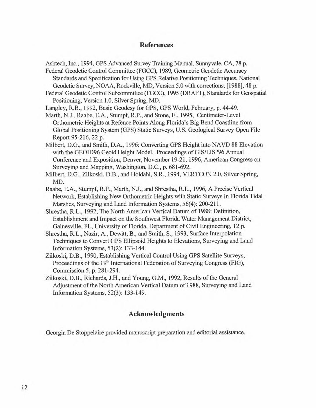
MethodsThree steps are critical to quality GPS vertical surveys: 1) survey planning and field
logistics, 2) survey execution, and 3) post-processing of the data. Cooperation from all parties made this a successful campaign. SRWMD and WRD participated in the planning, field logistics, and survey execution by providing information, transportation, manpower, access, and navigation to the sites.
Survey Planning and Field Logistics
Approximate dates of operation, obstruction diagrams, site locations, and constraints were considered in the planning phase. Several iterations of mission planning were required until time blocks were allocated to each site, allowed sufficient travel time between sites, and insured adequate visibility and availability of satellites for the required precision. Four or more satellites were mandatory for concurrent viewing from both the base station and the roving antenna. The configuration of the jointly viewed satellites also affected the precision of the measurements.
Options for site occupations in this survey were charted and preferred time frames with alternatives were selected. Contingency plans were discussed, and field crews were ready to take alternative steps when or if conditions changed. Mobility required a combination of trucks and water craft to move from one site to another. Field crews consisted of a base station operator, a driver, and the roving antenna carrier. An additional surveyor accompanied the forested estuarine site visits to facilitate traditional leveling to the forest transect.
The base stations used in the current survey (Figure 1) were established in a DGPS network in 1994-5 (Raabe et al., 1996). Keen, L210, is on County Road (CR) 349 near the cemetery. The elevation for L210 is used as published in the NGS database, 4.590 m NAVD88, and confirmed by Raabe et al. (1996). Dunn GPS, L201, is a replacement for L200 at the end of CR 349. L200 was destroyed during road improvement. The new GPS elevation established for Dunn GPS is 1.351 m NAVD88. Previously established obstruction diagrams for the base stations were field-checked for validity. Appendix 1 contains a description of Dunn GPS location and leveling.
Site locations were provided by WRD (Figure 1). Each site was evaluated for accessibility, method of transportation for access, and time required to move between sites. GPS surveys require an open view of the sky for satellite tracking. An obstruction diagram was established for all but the estuarine emergent sites, for which we assumed 360° visibility 10° above the horizon. Illustrations of water level gages were provided by SRWMD where accessibility, visibility, and positioning of the GPS receiver was an issue. WRD provided obstruction diagrams for the estuarine forest sites.
A combination of Ashtech Z-12 and Z-Surveyor receivers were used in the survey. A fixed-height tripod, choke ring antenna, and Z-12 receiver operated as the base station with data logged to a laptop that was continuously monitored. A marine antenna mounted on a portable mono-pole and a Z-Surveyor receiver operated as the roving unit with a bipod for stability (Figure 2). Both the base and roving units logged data at 10 second intervals.

Figure 2. Base station on fixed tripod and portable roving antenna.

Survey execution
Two attempts were made to secure the elevations of the gages and transects. The first attempt on January 26-28, 1998, was aborted due to equipment failures and errors. Successful surveys were conducted in April 1998. Julian days, in the format J_, are used in the GPS data collection format. The DGPS surveys for the Lower Suwannee marsh and water gage sites were conducted April 20-21, J110-J111, by the GD team, and by Rob Mattson and John Good of SRWMD (Table 1). The DGPS survey for the estuarine forest sites was conducted April 29-30, J119-J120, by the GD team, and by Helen Light and Lori Lewis of WRD, and Erik Lewis of SRWMD (Table 2).
Table 1. GPS occupation of Lower Suwannee sites April 20-21,1998.
Site#
DAY1 J110AA99AA16AA15AA14AA19AA19AB19AA15AA01AA20AA20AA03*AA17 fAA18AA99AA99DAY 2 JillBB99BB03 fBB20BB17BB18BB05BB05BB04BB45BB45BB02
BB92BB18BB99BB99
Occupation (mm)
15 (initialized) *22222 (re-occupy)22 (re-occupy)22 *
10 (re-occupy) *3*2 *2*
2 (re-occupy) *15 (re-initialize) *
15 (initialize) *2*2 *2 *2 *
22 (re-occupy)22 *
2 (re-occupy) *2
22 (re-occupy) *4 (re-occupy) *15 (re-initialize) *
Notes
Angler's Resort BenchmarkUpper West Pass marsh transect - steel rod in PVCMiddle West Pass marsh transect - steel rod in PVCLower West Pass marsh transectSalt Creek, top of PVC casingSalt Creek, top of PVC casingSalt Creek, steel rod in PVC^Middle West Pass marsh transectLower West Pass gage, steel rodDan May Creek marsh transect)an May Creek marsh transect
Lower East Pass gageLower East Pass marsh transectUpper East Pass marsh transectAngler's Resort benchmarkAngler's Resort benchmark
Angler's Resort benchmarkLower East Pass gageDan May Creek marsh transectLower East Pass marsh transectUpper East Pass marsh transectUpper East Pass gage aluminum bracket on concrete pilingUpper East Pass gageGopher River gage base of gage box interiorTreasure Camp boat ramp - "x" scratched in concreteTreasure Camp boat ramp - "x" scratched in concreteJpper West Pass gage aluminum bracket holding pole to piling; orange (A)Jpper West Pass gage nail on wood deck sprayed orange (B)Jpper East Pass marsh transectAngler's Resort benchmarkAngler's Resort benchmark

Table 2. GPS occupation of Lower Suwannee sites April 29-30,1998.Site#
DAY 3 J119CC80CC81CC45CC45ecuCC12CC30CC13CC09CC09CC30CC08CC45 *CC81L210CC99CC80DAY 4 J120DD81DD06DD45DD07DD81
Occupation (min)
15 (initialize)3 **10*2*
5555510 (re-occupy)5 (re-occupy)55 (re-occupy) *5 (re-occupy) **5*5*
10 (re-initialize)
10 (initialize) **1010**
1010 (re-initialize)
Notes
Survey nail (#1) in road across from Dunn GPS (Appendix 1)Keen High Water Mark; nail in roadTreasure Island Boat Ramp ("x")Treasure Island Boat Ramp (nail on "x")Sandfly transect, survey nail on stakeGopher River; nail on stake in open marsh areaMcCormick Creek; nail on stake3arnett Creek transect; nail on stakeAlternate Sandfly; nail on stakeAlternate SandflyMcCormick CreekTurkey Island transect; nail on stakeTreasure Island Boat Ramp; nail on "x"Keen High Water Mark; nail in road; level to nail in treeKeen BM L210-L210 baseline repeatAngler's Resort benchmarkle-initialize on survey nail near DunnGPS
Keen High Water Mark; nail in roadview Clay Landing; nail in boat ramp wallTreasure Island Boat Ramp; nail on "x"
Keen Transect; nail in stake in open area&een High Water Mark; nail in road
**
t
Indicates multiple-day occupation of vector (base station to site). Multiple-day occupation of position, but different base station. Unsuccessful or erroneous data collection during site occupation.
Base station L201 was occupied for the first three days, J110, Jill, and J119. L210 served as the base location for the fourth day, J120. Positions occupied on J110 were prefixed with "A," Jill with "B," J119 with "C," and J120 with "D".
The base station was set up to record all day on an Ashtech Z-12 with a laptop for data logging due to memory limitations of the Ashtech receivers. Initialization of the roving unit was conducted nearby for 15 minutes. The roving antenna was moved to each subsequent site for a 2-5 minute occupation. Final re-initialization was conducted at the end of the day at the initialization site. If loss of lock on satellites occurred during transport, then the next station was subsequently occupied 5-10 minutes. The battery of the roving unit typically lasted approximately 5 hours. Once a new battery was installed, the rover was re-deployed at the location occupied prior to the exchange.
Two to five sites were re-occupied during the course of each day for verification and accuracy evaluation. Sites were also re-occupied on subsequent days. Re-initializations, re-occupations, and multiple-day occupations are noted in Tables 1 and 2. Comparisons of the length of vectors from re-occupations provide an additional check for errors and accuracy.

Post-processing and Results
Post-processing of the field data was completed with Ashtech post-processing software, PNAV version 2.5, using Forward and Backward survey processing for the PL 1-code/PL2-code/PL2-phase and CALl-phase wave measurements (Ashtech, 1994). Ashtech's Prism software was used for adjustment analysis to examine the overall network fit of the vectors. Data was examined for cycle slips, high PDOP, high vector residuals, a high network standard error, or fewer than 6 satellites. Valid surveys must have low position dilution of precision (PDOP), preferably < 5. Vectors with high PDOP, less than 5 satellites, or high standard deviations were eliminated from final calculations of ellipsoid heights.
Ellipsoid heights were converted to orthometric heights using the NAVD88 datum and the Geoid96 geoid model. Final orthometric heights in meters are shown in Table 3.
Table 3. DGPS-derived orthometric heights.
Site NA VD88 (m) NGVD29 (m/ft) Latitude & Longitude NAD83
Angler's Resort Benchmark 1.070m 1.268m/4.16ft 29 19 48.030 83 08 35.547
Suwannee River Delta Marsh Transect Sites:Upper West Pass Marsh Transect 0.414mMiddle West Pass Marsh Transect 0.218mLower West Pass Marsh Transect 0.200 mLower East Pass Marsh Transect 0.359mUpper East Pass Marsh Transect 0.529mSalt Creek Marsh Transect A 0.427mSalt Creek Marsh Transect B 0.246mDan May Creek Marsh Transect 0.319m
0.612m/2.00ft 0.417m/1.37ft 0.399m/1.30ft 0.557m/1.82ft 0.727m/2.39ft 0.625m/2.05ft 0.444m/1.45ft 0.516m/1.69ft
29 18 56.443291831.579291825.79029 17 9.565291752.801292018.592292018.591291740.956
Lower Suwannee River Gage Sites:Lower East Pass Gage Upper East Pass Gage Gopher River Gage Upper West Pass Gage A Upper West Pass Gage B Lower West Pass Gage
Lower Suwannee River EstuarineTreasure Camp Boat Ramp Sandfly Transect Gopher RiverMcCormick Creek Marsh site Barnett Creek Transect Alternate Sandlfy Site Turkey Island Transect Keen High Water Mark New Clay Landing Keen Transect
orthometric height not available
2.014m 3.735m 1.895m 3.016m 0.224m
83 08 46.85783 09 34.36583 10 7.78883 06 45.492830641.51683 08 49.45983 08 49.45883 05 40.364
2.212m/7.26ft 3.932m/12.90ft 2.093m/6.86ft 3.214m/10.55ft 0.422m/1.38ft
291841.903 291940.909 291928.097 291928.422 291842.839
83 07 8.709 83 06 14.507 83 08 27.428 830827.631 830851.793
Forest Sites:1.844m1.203m0.783m0.837m0.815m1.284m1.953m3.607m2.398m1.550m
2.040m/6.69ft1.399m/4.59ft0.980m/3.21ft1.034m/3.39ft1.012m/3.32ft1.480m/4.85ft2.149m/7.05ft3.805m/12.48ft2.598m/8.52ft1.748m/5.73ft
292347.413291948.858291937.61629 18 19.24629 18 44.37929 19 29.703292157.401292651.7452931 5.274292631.995
83 01 34.01283 03 59.03683 04 37.787830420.133830420.41783 04 6.866830254.71183 01 36.28682 58 12.64683 01 20.483

Accuracy of the NAVD88 orthometric heights is + 3 cm at the 95% confidence interval. Conversion to NGVD29 with VERTCON software is provided in meters and in feet for users still employing the older datum. The conversion to NGVD29 adds an additional error of + 4 cm at the 95% confidence level (Milbert et al., 1994). Again, errors are cumulative. Horizontal positions are given as latitude and longitude in North American Datum 1983 (NAD83). The World Geodetic System 1984 (WGS84) coordinates provided by the GPS system are almost identical to NAD83 (Langley, 1992; Shrestha et al., 1993).
No trend was detected between GPS-derived heights and traditional leveling (Appendix 2). While traditional leveling heights vary slightly from GPS-derived heights, the difference does not exceed the expected error range of+ 2-4 cm. We are confident that the GPS-derived elevations are congruent with the elevations obtained along the Upper Suwannee River from traditional leveling techniques.
Replication of site occupations were conducted to provide verification and validation of elevations and vector lengths between the base station and individual sites. The length of vectors occupied on same and subsequent days are shown in meters in Table 4. Vector lengths between replicated site occupations show an acceptable range in variation. Repeat vectors were from 10 -18,000 m in length, yet consistently differ by less than 4 cm on repeat occupations. Repeat vectors with high standard deviations in both forward and backward processing and other data errors were eliminated from the analysis.
Note that the variation in vector length should not be interpreted solely as an error in vertical placement. The length of a vector between the base station and the site includes variation in both horizontal and vertical placement of the position in question.
A second base station, Keen, L210, was occupied on the fourth day, J120, to minimize vector length between base station and sites occupied by the roving antenna (Figure 1). As a result, while rover site occupations may have been repeated on J120, vector lengths are not comparable from "D" sites to "A," "B," or "C" sites. As an additional check, base to base vectors were observed between the two base stations on J119 and J120. Comparison of these vector lengths with a previous vector observation in 1998 is included in Table 4. The three 15 km vectors vary by less than 2 cm for overall survey reliability. The orthometric height obtained for the Keen benchmark, L210, from this survey is 4.590 m NAVD88. This height corresponds exactly with the published NGS position (Appendix 1).
Discussion
Orthometric heights (NAVD88) were established for 22 locations in the 1998 DGPS survey with + 3 cm accuracy at the 95% confidence interval. The horizontal and vertical location of the Lower East Pass gage mark was not secured in this survey due to data errors during both occupations of the site.
WRD installed a brass plate in the town of Suwannee at the Angler's Resort. The benchmark is on the patio behind the store alongside the canal (Figure 3). This site was occupied several times by the roving antenna during the first three days for initialization. While the benchmark is not essential to the vegetation surveys, it does provide an

additional and accessible vertical benchmark with centimeter-level accuracy in the town of Suwannee.
Several occupied sites are not retrievable, nor repeatable. They were temporary positions that served as markers for the traditional leveling conducted by the investigators of the monitored transects. Caution should be exercised in surveying from any of the sites described as "nail on stake" or "nail in road," beyond the initial surveying conducted immediately following the GPS survey. Those sites, which are described as steel rod in poly vinyl chloride (PVC) casing, may be relatively stable for some time in the future. The water level gages may be considered stable barring major storms or boat impact. A nail on concrete at a boat ramp may also be considered stable for some time into the future.
Table 4. Vector length variation from multiple occupations.Base Station toSite#
AA99BB99CC99AA15AA18BB18AA19AA20BB20BB05BB45CC45CC09CC30CC80CC81DD81
Vectorl (m)
924.156924.169924.1592180.7855122.0325122.0371330.9926672.0356672.0413662.01314445.63214445.6058130.6538143.52610.73218063.4762485.417
L201-L210 J119 1998L201-L210 J120 1998L201-L210 J356 1997
Vector2 (m)
924.175924.174
2180.746
5122.0061330.9956672.046
3661.99714445.64314445.6068130.6598143.55110.73318063.4912485.420
VectorS (m)
924.177924.169
10.738
15696.333
15696.340
15696.323
Difference (m)/ Between days '(m)
0.0210.005/0.018
0.039
0.031/0.0280.0030.011/0.006
0.0160.0110.001/0.0380.0060.0250.0060.0150.003
0.017
10

Figu
re 3
. A
ngle
r's R
esor
t ben
chm
ark
loca
ted
on p
atio
bet
wee
n bo
at c
anal
and
Ang
ler's
Res
ort s
tore
on
Cou
nty
Roa
d 34
9 in
Suw
anne
e, F
lorid
a.
References
Ashtech, Inc., 1994, GPS Advanced Survey Training Manual, Sunnyvale, CA, 78 p. Federal Geodetic Control Committee (FGCC), 1989, Geometric Geodetic Accuracy
Standards and Specification for Using GPS Relative Positioning Techniques, NationalGeodetic Survey, NOAA, Rockville, MD, Version 5.0 with corrections, [1988], 48 p.
Federal Geodetic Control Subcommittee (FGCC), 1995 (DRAFT), Standards for GeospatialPositioning, Version 1.0, Silver Spring, MD.
Langley, R.B., 1992, Basic Geodesy for GPS, GPS World, February, p. 44-49. Marth, N.J., Raabe, E.A., Stumpf, R.P., and Stone, E., 1995, Centimeter-Level
Orthometric Heights at Refence Points Along Florida's Big Bend Coastline fromGlobal Positioning System (GPS) Static Surveys, U.S. Geological Survey Open FileReport 95-216, 22 p.
Milbert, D.G., and Smith, D.A., 1996: Converting GPS Height into NAVD 88 Elevationwith the GEOID96 Geoid Height Model, Proceedings of GIS/LIS '96 AnnualConference and Exposition, Denver, November 19-21,1996, American Congress onSurveying and Mapping, Washington, D.C., p. 681-692.
Milbert, D.G., Zilkoski, D.B., and Holdahl, S.R., 1994, VERTCON 2.0, Silver Spring,MD.
Raabe, E.A., Stumpf, R.P., Marth, N.J., and Shrestha, R.L., 1996, A Precise VerticalNetwork, Establishing New Orthometric Heights with Static Surveys in Florida TidalMarshes, Surveying and Land Information Systems, 56(4): 200-211.
Shrestha, R.L., 1992, The North American Vertical Datum of 1988: Definition,Establishment and Impact on the Southwest Florida Water Management District,Gainesville, FL, University of Florida, Department of Civil Engineering, 12 p.
Shrestha, R.L., Nazir, A., Dewitt, B., and Smith, S., 1993, Surface InterpolationTechniques to Convert GPS Ellipsoid Heights to Elevations, Surveying and LandInformation Systems, 53(2): 133-144.
Zilkoski, D.B., 1990, Establishing Vertical Control Using GPS Satellite Surveys,Proceedings of the 19th International Federation of Surveying Congress (FIG),Commission 5, p. 281-294.
Zilkoski, D.B., Richards, J.H., and Young, G.M., 1992, Results of the GeneralAdjustment of the North American Vertical Datum of 1988, Surveying and LandInformation Systems, 52(3): 133-149.
Acknowledgments
Georgia De Stoppelaire provided manuscript preparation and editorial assistance.
12

Appendix 1
Establishment of New Benchmark, Dunn GPS 1997
Base stations for DGPS surveying must be clear of overhead and vertical obstructions for adequate satellite tracking. In 1994 the Dunnary RM3 benchmark was relocated to a nail using a laser level with closure at + 0.0006 m (Marth et al., 1995). The new location permitted satellite tracking with a GPS antenna. This position was occupied in the Big Bend GPS network as L200 (Raabe et al., 1996). Road improvements in the intervening years destroyed the adjusted position of L200.
Late in 1997 a new monument, Dunn GPS 1997 was established nearby, beyond the impact of road activities. Steel rebar was driven to refusal and encased in a cement footing. A USGS brass benchmark was installed on the rebar just below ground surface, and stamped Dunn GPS 1997. The new location is at the end of CR 349 in Suwannee.
To locate the benchmark, begin at Old Town in Dixie County, Florida. Turn south on CR 349 from US 98/27A. Continue on CR 349 until it ends at Barbree Circle in the town of Suwannee. The benchmark is installed behind the left, or south end of the guard rail. It is 0.4 m behind or southwest of the southernmost guard rail post and 2.0 m east of riprap along the Salt Creek canal (Figure 4). It is covered by 0.05-0.08 m of sandy soil. Two sabal palms form a clump of vegetation 1 m northwest of the benchmark. Another larger sabal palm stands several meters southwest of the benchmark.
The site should be stable for some years. The guard rail and a flashing red light were installed due to motorists driving over the edge into the Salt Creek canal. Although there is some potential for a large storm surge to erode the canal, a pile of riprap along the canal's edge does provide some protection.
The position was laser-leveled to benchmarks Dunnary, RM2, and RM3 in the Barbree Circle with a loop closure of 0.0026 m. The Dunnary benchmarks are not suitable for GPS surveying due to excessive overhead obstructions.
Elevation of the new benchmark was established with DGPS surveying. The station was occupied in 1997 and 1998 with simultaneous occupations of previous networked benchmarks, Keen, Barrow 2, and FLGS 35 (Raabe et al., 1996). See Table 5 for horizontal and vertical positions of benchmarks utilized in this survey. An adjustment of vectors between Dunn GPS 1997 and the established benchmarks secured the new GPS- derived orthometric height of 1.351 m NAVD88, and a horizontal position of 29 19 38.548 83 09 08.046 (NAD83). Vertical precision is 1 ppm at one sigma with a standard deviation of less than 0.02 m vertical. For data collection purposes, Dunn GPS 1997 is referred to as L201.
13

Table 5. Horizontal and vertical controlPublished Designation
Dunn GPSKeenBarrow 2FLOPS 35
Survey Site #
L201L210L220L230
Horizontal and Vertical Order
unpublished1H.2VBH, 1V/HARNBH
Latitude/Longitude (NAD83)
29 19 38.548 083 09 08.046292539.15126 0830216.61863292829.04147 0824943.77412290951.31877 0823824.33711
Pub. Orthometric Height NAVD88 (m)
*1.3514.590
12.895* 10.766
* Unpublished GPS-derived Orthometric height
Several survey nails were installed nearby and laser-leveled as backup due to the history of alterations in the area (Figure 5). Table 6 presents the leveling relationship to Dunn GPS and the derived Orthometric heights for each nail.
Table 6. Orthometric height of nailsNail
Nail#lNail #2Nail #3Nail #4Nail #5
Leveled difference to Dunn GPS (m)-0.166+0.581-0.127-0.214+0.078
Derived Orthometric Height (m)
1.185**
1.9321.2231.1371.429
** Nail #1 was also included in the GPS survey on Day 3 as CC80. The GPS- derived height of 1.161 m NAVD88 is -0.024 m from the leveled elevation of 1.185. This negative 2-3 cm difference is congruent with data presented in Appendix 2.
14

Figu
re 4
. Lo
catio
n of
Dun
n G
PS 1
997
at th
e en
d of
Cou
nty
Roa
d 34
9 in
the
tow
n of
Suw
anne
e, F
lorid
a.

Canal
DUNN GPS 1997
\ \Barbree Circle Wr"Private Rd
Guard Rail
End CR349
o.
Barbree Circle
o.
Utility pole
To Town of Suwannee
N
Location of survey nails:
1. Located to the left at turn onto Barbree Circle on edge of pavement ~1S ft west from utility pole.
2. Located on top of southern-most post of guard rail - in front (northeast) of benchmark (18").
3. Located east of northern-most guardrail post ~ 12.S feet.
4. South of willow tree ~24.S ft - next to second piling from left on asphalt driveway - last house on right.
5. Edge of pavement - Barbree Circle ~26.5 ft NE of private road sign.
Location of Base Station (Dunn GPS):
1. Located 18" behind far left guard rail post.
Figure 5. Location of survey nails and Dunn GPS 1997 at end of County Road 349.
16

Appendix 2
GPS-Derived Heights versus Published Heights
Surveying with GPS satellites requires overhead visibility. Several published benchmarks were located in the vicinity of the survey, but were not suitable for GPS survey occupation because of overhead obstructions. What follows is a brief discussion of the relation between the published adjusted NAVD88 ormometric heights and heights derived from leveling to GPS-occupied sites.
Three benchmarks, Dunnary, Dunnary RM2, and Dunnary RM3, are located on Barbree Circle in Suwannee. Each of the published benchmarks were recovered and laser-leveled to the new Dunn GPS benchmark located in the open area nearby. Table 7 presents the published orthometric height of the original benchmark, the leveling difference to Dunn GPS, and the height of the benchmark as derived from Dunn GPS. The difference between the published height and the derived height is negative 2-3 cm in all three cases. Our leveling between the three published benchmarks establishes Dunnary 1 cm higher in relationship to both RM2 and RM3. This could explain the minor difference in the final comparison with Dunn GPS.
SRWMD leveled from benchmark, A 15 FLDNR, to the Gopher River gage with a difference of 4.07', or 1.241 m. The derived elevation of A 15 FLDNR from the Gopher River gage presents a height difference of+0.034 m. Traditional leveling methods were also employed to establish the relationship between the Treasure Camp boat ramp GPS location and a nearby tidal station, 872 7512 A Tidal. The resulting difference between the published height and the height derived from the GPS position is +0.017 m.
The comparisons presented here show + 2-4 cm difference between the published NAVD88 height and the height as leveled to the GPS-derived height at a nearby satellite observation position. Considering the cumulative sources of error from both an adjusted NAVD88 published height and the GPS-derived error range, these differences are well- within reason. While these results do not offer a consistent adjustment between GPS- derived and leveled survey heights, they do provide additional assurance of the overall survey accuracy and reliability.
Table 7. Comparison of published and derived heightsBenchmark and Nearby GPS Position
Dunnary to Dunn GPSRM2 to Dunn GPSRM3 to Dunn GPSA 15 FLDNR to Gopher River gage872 75 12 A Tidal to Treasure Camp boat ramp "x"
Published BMOrth.Ht. (m)NAVD88
1.7782.2131.3052.528
1.924
GPS-derived Ht. of nearby GPSposition
1.3511.3511.3513.735
1.844
Leveled difference (m)
+0.041+0.830-0.077
+1.241
+0.097
Derived Height from GPS and Leveling
1.7582.1811.2743.769
1.941
Difference (m)from Published Height
-0.020-0.032-0.031+0.034
+0.017
17