gps/3g/4g 4/8ch,d1,hard disk mobile digital video recorder ...€¦ · hard disk mobile dvr user...
TRANSCRIPT
1
User Manual for
GPS/3G/4G, 4/8ch,D1,Hard Disk
Mobile Digital Video Recorder(MDVR)
Model:
Hard Disk Mobile DVR User Manual V2.2
2
Catalogue
1. PRODUCT SPECIFICATION ................................................................................................................................. 4
1.1 PRODUCT OVERVIEW .................................................................................................................................................. 4
1.2 KEY FEATURES ........................................................................................................................................................... 4
1.3 MDVR DETAIL SPECIFICATIONS TO SEE TABLE 1 ................................................................................................................ 4
1.4 MDVR ELECTRIC SPECIFICATIONS TO SEE TABLE 2 ............................................................................................................. 6
1.5 PRODUCT APPLICATIONS .............................................................................................................................................. 6
2. APPEARANCE OF PRODUCT .............................................................................................................................. 7
2.1 DEVICE APPEARANCE .................................................................................................................................................. 7
2.2 DEVICE DRAWING DIMENSION & INSTALL HOLES .............................................................................................................. 8
2.3 FRONT & BACK PANEL LED & PLUG-IN MODULE. .............................................................................................................. 9
2.4 BACK PANEL INTERFACE DEFINITION ............................................................................................................................. 10
2.5 POWER CABLE ......................................................................................................................................................... 12
2.6 GPS ANTENNA AND 3G/4G ANTENNA......................................................................................................................... 13
2.7 ALARM INPUT AND OUTPUT ....................................................................................................................................... 13
2.8 DEVICE INSTALLATION GUIDE ...................................................................................................................................... 13
3. REMOTE CONTROL FUNCTION INSTRUCTION .................................................................................................. 18
3.1 REMOTE CONTROL ................................................................................................................................................... 18
3.2 TEXT INPUT ............................................................................................................................................................. 20
3.3 VIDEO SETTINGS ....................................................................................................................................................... 20
3.4 PTZ CONNECTION WAY AND SETTING ........................................................................................................................... 21
3.5 PC PLAYBACK OF THE VIDEO FILE .................................................................................................................................. 22
3.6 FAST REPORT BY VEHICLE SERVER ................................................................................................................................. 24
4. GENERAL SETTINGS ........................................................................................................................................ 26
4.1 DATE & TIME .......................................................................................................................................................... 26
4.2 VEHICLE SETTINGS .................................................................................................................................................... 27
4.3 USER MANAGEMENT SETTINGS ................................................................................................................................... 27
4.4 NETWORK SETTINGS ................................................................................................................................................. 28
5. RECORD SETTING............................................................................................................................................ 28
5.1 BASIC SETTINGS ....................................................................................................................................................... 28
5.2 MAIN CODE ............................................................................................................................................................ 29
5.3 SUB-STREAM ........................................................................................................................................................... 30
5.4 RECORDING SCHEDULE (24 HOUR) .............................................................................................................................. 30
5.5 MIRROR RECORD(OPTIONAL) ..................................................................................................................................... 31
5.6 SD RECORD ............................................................................................................................................................ 31
5.7 ALARM RECORD (NOT SUPPORT TEMPORARILY) ............................................................................................................. 31
5.8 SPEED RECORD(OPTIONAL) ........................................................................................................................................ 32
6. ALARM SETTINGS ....................................................................................................................................... 32
6.1 SENSOR SETTINGS .................................................................................................................................................... 32
Hard Disk Mobile DVR User Manual V2.2
3
6.2 SPEED SETTINGS ...................................................................................................................................................... 33
6.3 G-SENSOR SETTINGS ................................................................................................................................................ 33
6.4 TEMPERATURE ALARM ............................................................................................................................................... 34
6.5 MOTION DETECTION ................................................................................................................................................ 34
6.6 LINKAGE SETTINGS ................................................................................................................................................... 35
6.7 OTHER ALARM ........................................................................................................................................................ 35
7. TOOLS ............................................................................................................................................................ 36
7.1 PARAMETER CONFIGURATION ..................................................................................................................................... 36
7.2 FORMAT ................................................................................................................................................................. 36
7.3 LOG SEARCH ........................................................................................................................................................... 37
8. PERIPHERAL SETTINGS.................................................................................................................................37
8.1 PTZ SETTINGS ......................................................................................................................................................... 37
8.2 3G/4G SETTINGS ..................................................................................................................................................... 38
8.3 WIFI SETTINGS ....................................................................................................................................................... 38
8.4 OIL SETTINGS .......................................................................................................................................................... 39
8.5 SERIAL ................................................................................................................................................................... 39
9.RECORD SEARCH ............................................................................................................................................. 40
10. SYSTEM INFO ................................................................................................................................................ 40
APPENDIX 1: CMSSERVER PLATFORM INTERFACE ................................................................................................ 41
APPENDIX 2: COMMON PROBLEMS AND TREATMENT ........................................................................................ 41
APPENDIX 3:STORAGE SPACE CORRESPONDING TABLE........................................................................................ 44
APPENDIX 4:MDVR BEFORE LOADING THE TOOL TO CHECK ................................................................................. 44
APPENDIX 5:MDVR BEFORE LOADING THE INSTALLATION OF AUXILIARY EXAMINATION ..................................... 45
*The final interpretation of the specification, pictures and text interpretation all belong to
the company. Without notice when content is changed!
Hard Disk Mobile DVR User Manual V2.2
4
1. Product Specification
1.1 Product Overview
Hard Disk Mobile DVR (Automotive) is a cost-effective, multi-functional device designed for video
surveillance and remote monitoring of your mobile assets. It uses a high-speed processor, an
embedded Linux platform, and the most advanced technology in the IT field, such as H.264 Video
Compression/Decompression, 3G/4G network transmission technology and GPS positioning
technologies. MDVR can realize four/eight channel video recording. Each channel supports CIF,
HD1 and D1 image solution. Drivers' driving information, GPS data and alarm data are recorded in
Hard disk which is used as the storage medium. The MDVR may look simple in its exterior design,
provides powerful auto black box features, installation flexibility and high reliability.
1.2 Key Features
4/8 channel video & audio synchronous real-time recording and playback
4ch D1@25fps; 6ch D1@25fps, 8ch HD1@25fps , 8ch CIF@25fps options.(PAL)
Built-in 2.5 inch HDD/SSD, supports max 1TB, Professional hard disk damping technology.
3G/4G network , such as HSUPA/HSDPA/WCDMA/EVDO is selectable.
Built-in GPS module.
Built-in G-sensor
External WIFI special interface.
Built-in 1 SD card for backup recording when HDD/SSD errors.
2 high speed USB2.0 interfaces, the front is used to export record file. The back is use to mirror
recording for waterproof and fireproof.
8 digital alarm inputs, 2 digital level output.
3 RS485 interfaces, 1 RS232 interface.
Built-in hard disk heating technology. It can be worked in -25℃~+70℃.
Power supply: 8V~36V
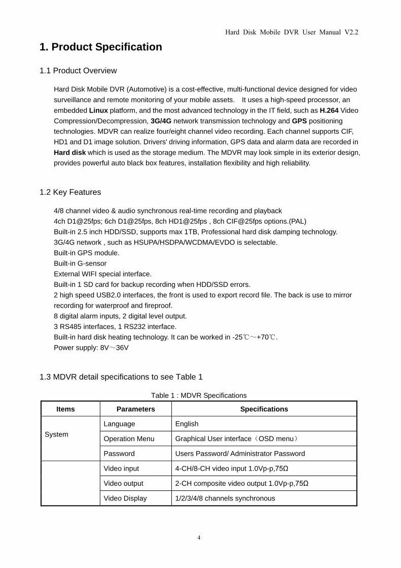
1.3 MDVR detail specifications to see Table 1
Table 1 : MDVR Specifications
Items Parameters Specifications
System
Language English
Operation Menu Graphical User interface(OSD menu)
Password Users Password/ Administrator Password
Video input 4-CH/8-CH video input 1.0Vp-p,75Ω
Video output 2-CH composite video output 1.0Vp-p,75Ω
Video Display 1/2/3/4/8 channels synchronous
Hard Disk Mobile DVR User Manual V2.2
5
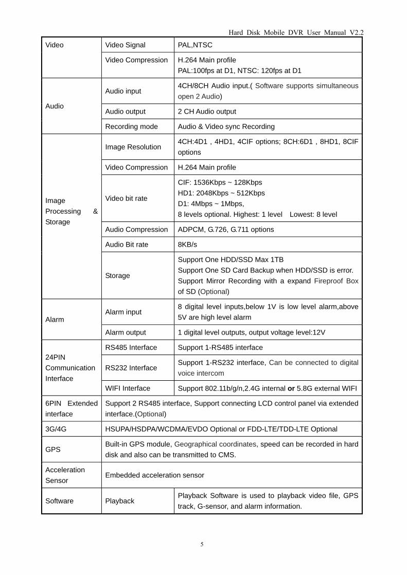
Video Video Signal PAL,NTSC
Video Compression H.264 Main profile
PAL:100fps at D1, NTSC: 120fps at D1
Audio
Audio input 4CH/8CH Audio input.( Software supports simultaneous
open 2 Audio)
Audio output 2 CH Audio output
Recording mode Audio & Video sync Recording
Image
Processing &
Storage
Image Resolution 4CH:4D1 , 4HD1, 4CIF options; 8CH:6D1 , 8HD1, 8CIF
options
Video Compression H.264 Main profile
Video bit rate
CIF: 1536Kbps ~ 128Kbps
HD1: 2048Kbps ~ 512Kbps
D1: 4Mbps ~ 1Mbps,
8 levels optional. Highest: 1 level Lowest: 8 level
Audio Compression ADPCM, G.726, G.711 options
Audio Bit rate 8KB/s
Storage
Support One HDD/SSD Max 1TB
Support One SD Card Backup when HDD/SSD is error.
Support Mirror Recording with a expand Fireproof Box
of SD (Optional)
Alarm Alarm input
8 digital level inputs,below 1V is low level alarm,above
5V are high level alarm
Alarm output 1 digital level outputs, output voltage level:12V
24PIN
Communication
Interface
RS485 Interface Support 1-RS485 interface
RS232 Interface Support 1-RS232 interface, Can be connected to digital
voice intercom
WIFI Interface Support 802.11b/g/n,2.4G internal or 5.8G external WIFI
6PIN Extended
interface
Support 2 RS485 interface, Support connecting LCD control panel via extended
interface.(Optional)
3G/4G HSUPA/HSDPA/WCDMA/EVDO Optional or FDD-LTE/TDD-LTE Optional
GPS Built-in GPS module, Geographical coordinates, speed can be recorded in hard
disk and also can be transmitted to CMS.
Acceleration
Sensor Embedded acceleration sensor
Software Playback Playback Software is used to playback video file, GPS
track, G-sensor, and alarm information.
Hard Disk Mobile DVR User Manual V2.2
6
CMS
Center vehicle management software platform, it can
manage more than 20000 devices at same time, if need
to manager more units, add more servers to realize it.
Software
Upgrade Support Flash disk to upgrade the firmware.
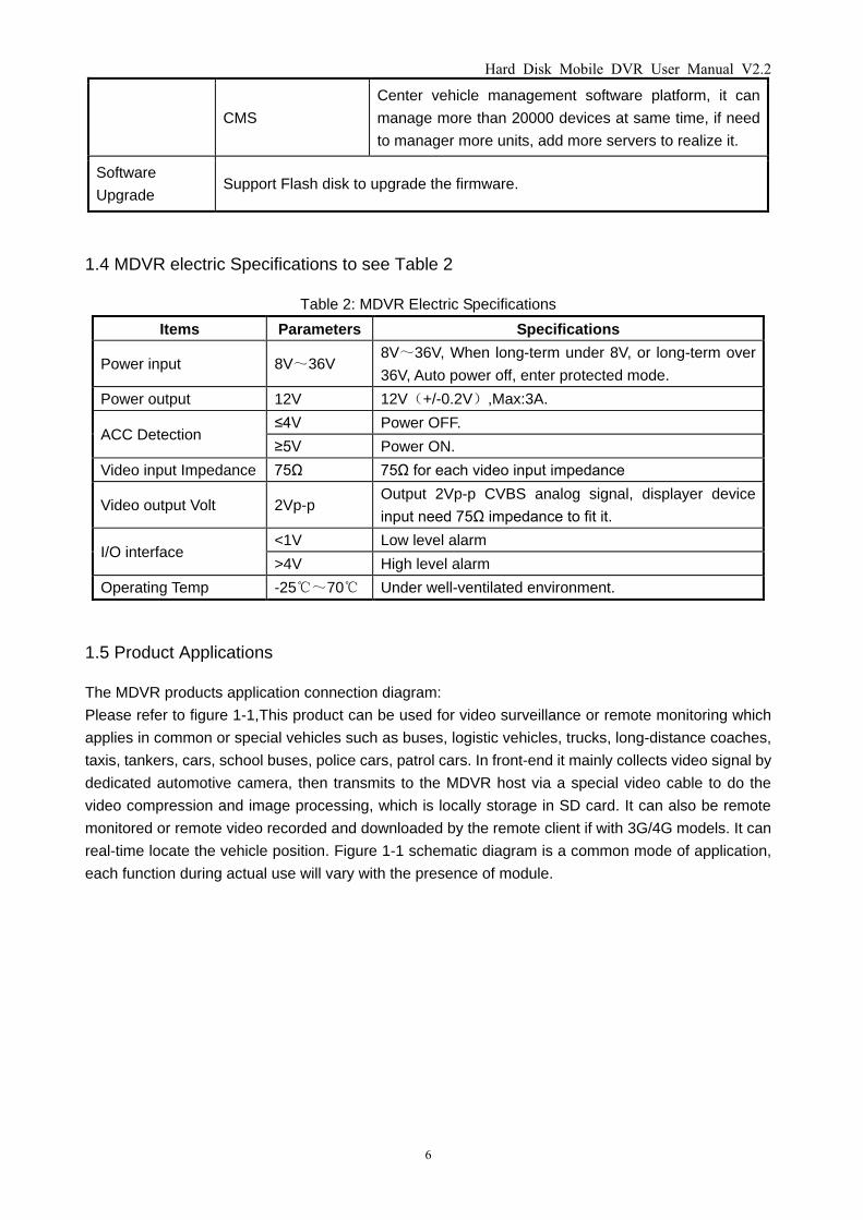
1.4 MDVR electric Specifications to see Table 2
Table 2: MDVR Electric Specifications
Items Parameters Specifications
Power input 8V~36V 8V~36V, When long-term under 8V, or long-term over
36V, Auto power off, enter protected mode.
Power output 12V 12V(+/-0.2V),Max:3A.
ACC Detection ≤4V Power OFF.
≥5V Power ON.
Video input Impedance 75Ω 75Ω for each video input impedance
Video output Volt 2Vp-p Output 2Vp-p CVBS analog signal, displayer device
input need 75Ω impedance to fit it.
I/O interface <1V Low level alarm
>4V High level alarm
Operating Temp -25℃~70℃ Under well-ventilated environment.
1.5 Product Applications
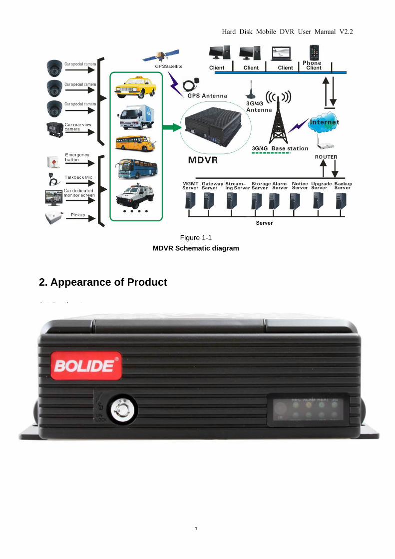
The MDVR products application connection diagram:
Please refer to figure 1-1,This product can be used for video surveillance or remote monitoring which
applies in common or special vehicles such as buses, logistic vehicles, trucks, long-distance coaches,
taxis, tankers, cars, school buses, police cars, patrol cars. In front-end it mainly collects video signal by
dedicated automotive camera, then transmits to the MDVR host via a special video cable to do the
video compression and image processing, which is locally storage in SD card. It can also be remote
monitored or remote video recorded and downloaded by the remote client if with 3G/4G models. It can
real-time locate the vehicle position. Figure 1-1 schematic diagram is a common mode of application,
each function during actual use will vary with the presence of module.
Hard Disk Mobile DVR User Manual V2.2
7
Figure 1-1
MDVR Schematic diagram
2. Appearance of Product
2.1 Device Appearance
Hard Disk Mobile DVR User Manual V2.2
8
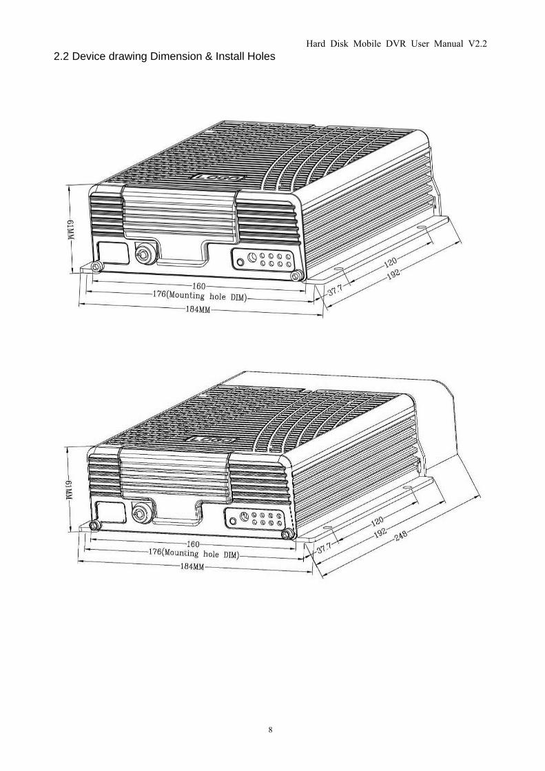
2.2 Device drawing Dimension & Install Holes
Hard Disk Mobile DVR User Manual V2.2
9
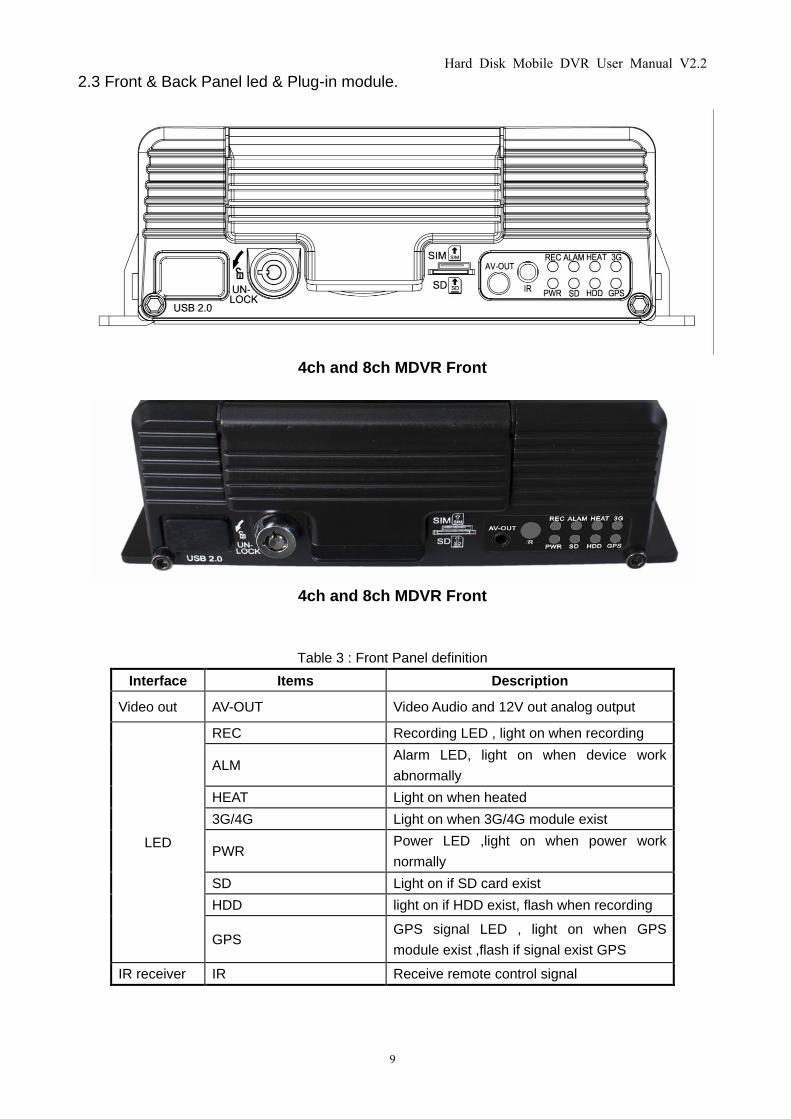
2.3 Front & Back Panel led & Plug-in module.
4ch and 8ch MDVR Front
4ch and 8ch MDVR Front
Table 3 : Front Panel definition
Interface Items Description
Video out AV-OUT Video Audio and 12V out analog output
LED
REC Recording LED , light on when recording
ALM Alarm LED, light on when device work
abnormally
HEAT Light on when heated
3G/4G Light on when 3G/4G module exist
PWR Power LED ,light on when power work
normally
SD Light on if SD card exist
HDD light on if HDD exist, flash when recording
GPS GPS signal LED , light on when GPS
module exist ,flash if signal exist GPS
IR receiver IR Receive remote control signal
Hard Disk Mobile DVR User Manual V2.2
10
Electronic
key LOCK
When device is working unlock the E-key,
system will power off ,lock the E-key .system
will work normally
USB Port USB 2.0 Upgrade and Export video data
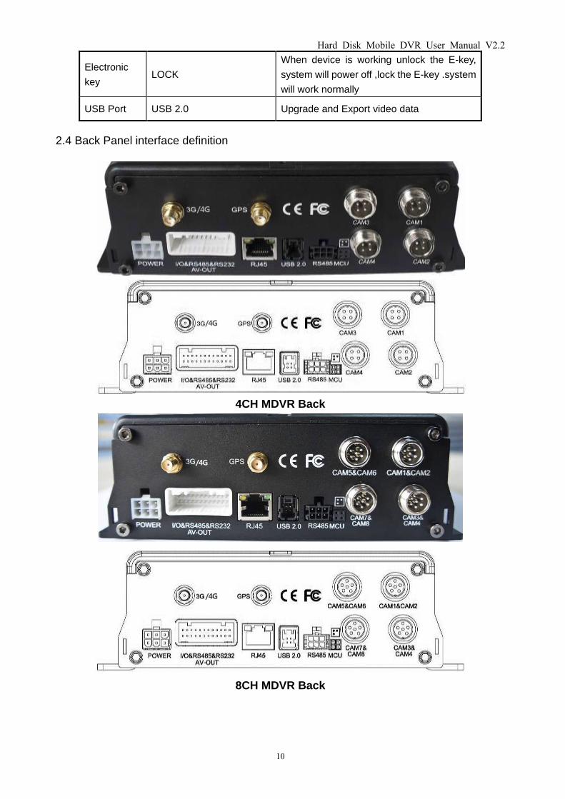
2.4 Back Panel interface definition
4CH MDVR Back
8CH MDVR Back
/4G
/4G
/4G
/4G
Hard Disk Mobile DVR User Manual V2.2
11
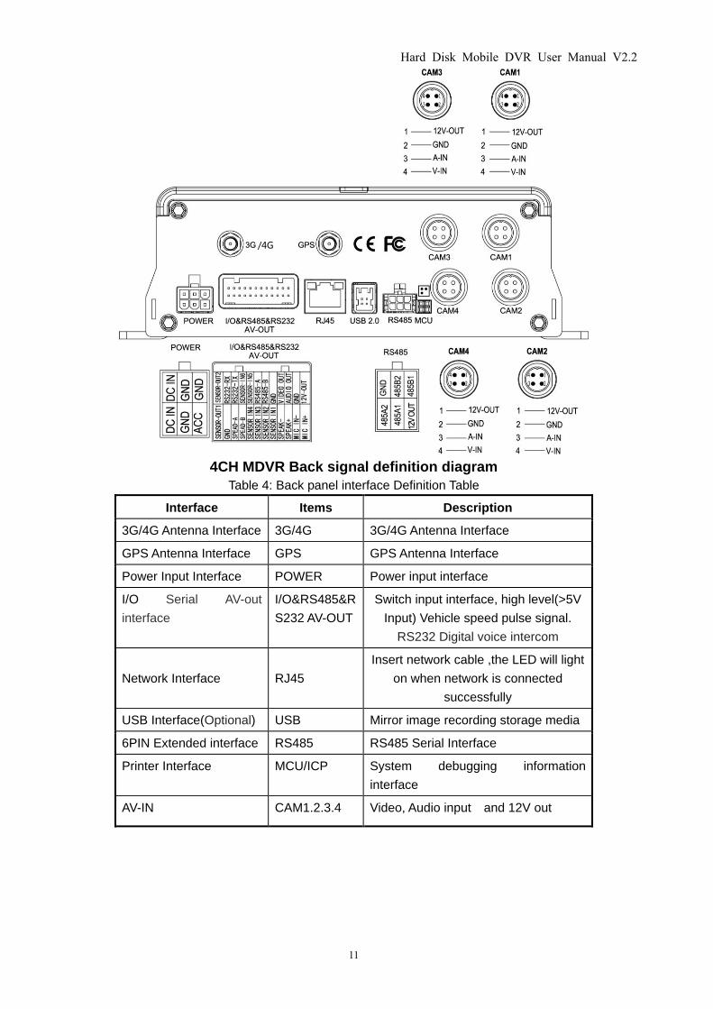
4CH MDVR Back signal definition diagram
Table 4: Back panel interface Definition Table
Interface Items Description
3G/4G Antenna Interface 3G/4G 3G/4G Antenna Interface
GPS Antenna Interface GPS GPS Antenna Interface
Power Input Interface POWER Power input interface
I/O Serial AV-out
interface
I/O&RS485&R
S232 AV-OUT
Switch input interface, high level(>5V
Input) Vehicle speed pulse signal.
RS232 Digital voice intercom
Network Interface RJ45
Insert network cable ,the LED will light
on when network is connected
successfully
USB Interface(Optional) USB Mirror image recording storage media
6PIN Extended interface RS485 RS485 Serial Interface
Printer Interface MCU/ICP System debugging information
interface
AV-IN CAM1.2.3.4 Video, Audio input and 12V out
/4G

Hard Disk Mobile DVR User Manual V2.2
12
2.5 Power Cable
Power cable as picture 9,one end is 6pin white plug , it connect with the 6pin white plug of device back
panel. The red and black cables are directly connect to the vehicle's battery. Red cable connect to
positive , black cable connect to negative . Yellow cable is FIREWIRE. The device will automatically
start when turn on the vehicle key ,and close when turn off the vehicle key . Yellow cable is connected
to the gear that vehicle key open all the dashboard light(the gear of starting vehicle motor ).
Notes:
1)Before connecting, confirm the voltage is between 8V—36V or else ,if over this range ,the device will
be fired
2)After connecting the cables, Ensure that power cables are insulated to prevent short circuiting and
burning out the battery.
3)The Yellow cable must be connected to the vehicle ignition cable, otherwise the device will not be
able to execute the delayed shutdown and the final moment of the video will be lost.
4)Note: Connection to the vehicle's engine must be connected directly to the positive anode of the
battery. Do Not Use bond strap for grounding as it will produce negative pulses that would interfere the
device's normal operation. The negative pole of the power code must be Φ1.5mm and above.
Hard Disk Mobile DVR User Manual V2.2
13
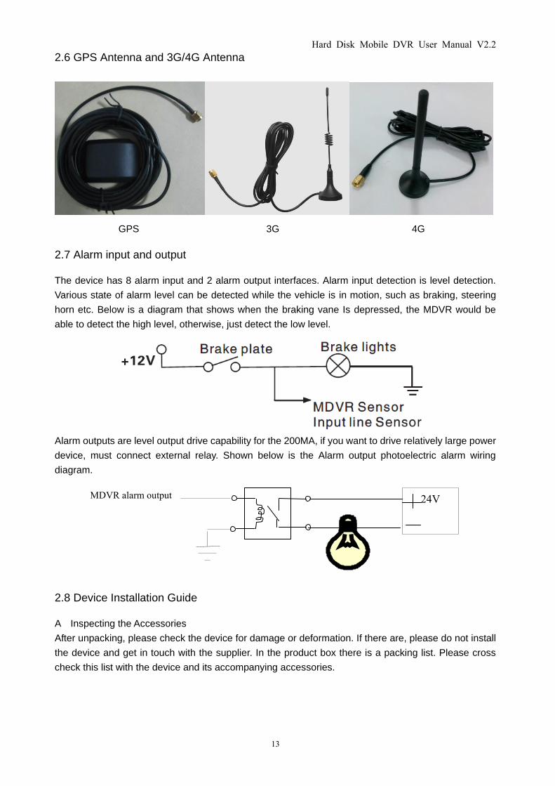
2.6 GPS Antenna and 3G/4G Antenna
GPS 3G 4G
2.7 Alarm input and output
The device has 8 alarm input and 2 alarm output interfaces. Alarm input detection is level detection.
Various state of alarm level can be detected while the vehicle is in motion, such as braking, steering
horn etc. Below is a diagram that shows when the braking vane Is depressed, the MDVR would be
able to detect the high level, otherwise, just detect the low level.
Alarm outputs are level output drive capability for the 200MA, if you want to drive relatively large power
device, must connect external relay. Shown below is the Alarm output photoelectric alarm wiring
diagram.
2.8 Device Installation Guide
A Inspecting the Accessories
After unpacking, please check the device for damage or deformation. If there are, please do not install
the device and get in touch with the supplier. In the product box there is a packing list. Please cross
check this list with the device and its accompanying accessories.
24V MDVR alarm output
Hard Disk Mobile DVR User Manual V2.2
14
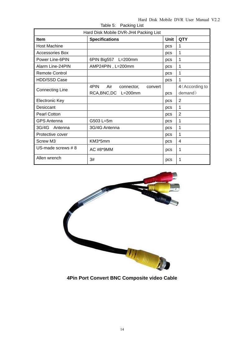
Table 5: Packing List
Hard Disk Mobile DVR-JH4 Packing List
Item Specifications Unit QTY
Host Machine pcs 1
Accessories Box pcs 1
Power Line-6PIN 6PIN Big557 L=200mm pcs 1
Alarm Line-24PIN AMP24PIN , L=200mm pcs 1
Remote Control pcs 1
HDD/SSD Case pcs 1
Connecting Line 4PIN Air connector, convert
RCA,BNC,DC L=200mm pcs
4(According to
demand)
Electronic Key pcs 2
Desiccant pcs 1
Pearl Cotton pcs 2
GPS Antenna G503 L=5m pcs 1
3G/4G Antenna 3G/4G Antenna pcs 1
Protective cover pcs 1
Screw M3 KM3*5mm pcs 4
US-made screws # 8 AC #8*9MM pcs 1
Allen wrench 3# pcs 1
4Pin Port Convert BNC Composite video Cable
Hard Disk Mobile DVR User Manual V2.2
15
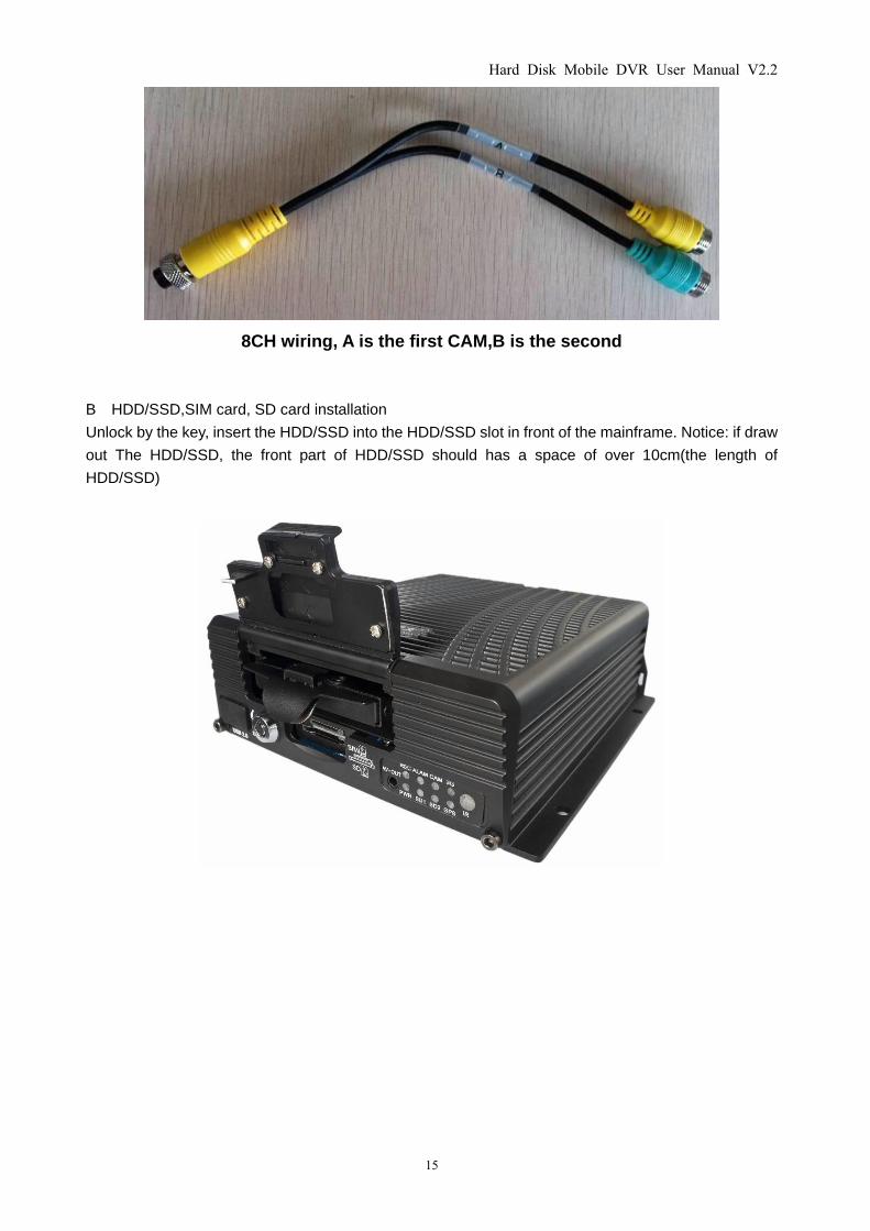
8CH wiring, A is the first CAM,B is the second
B HDD/SSD,SIM card, SD card installation
Unlock by the key, insert the HDD/SSD into the HDD/SSD slot in front of the mainframe. Notice: if draw
out The HDD/SSD, the front part of HDD/SSD should has a space of over 10cm(the length of
HDD/SSD)
Hard Disk Mobile DVR User Manual V2.2
16
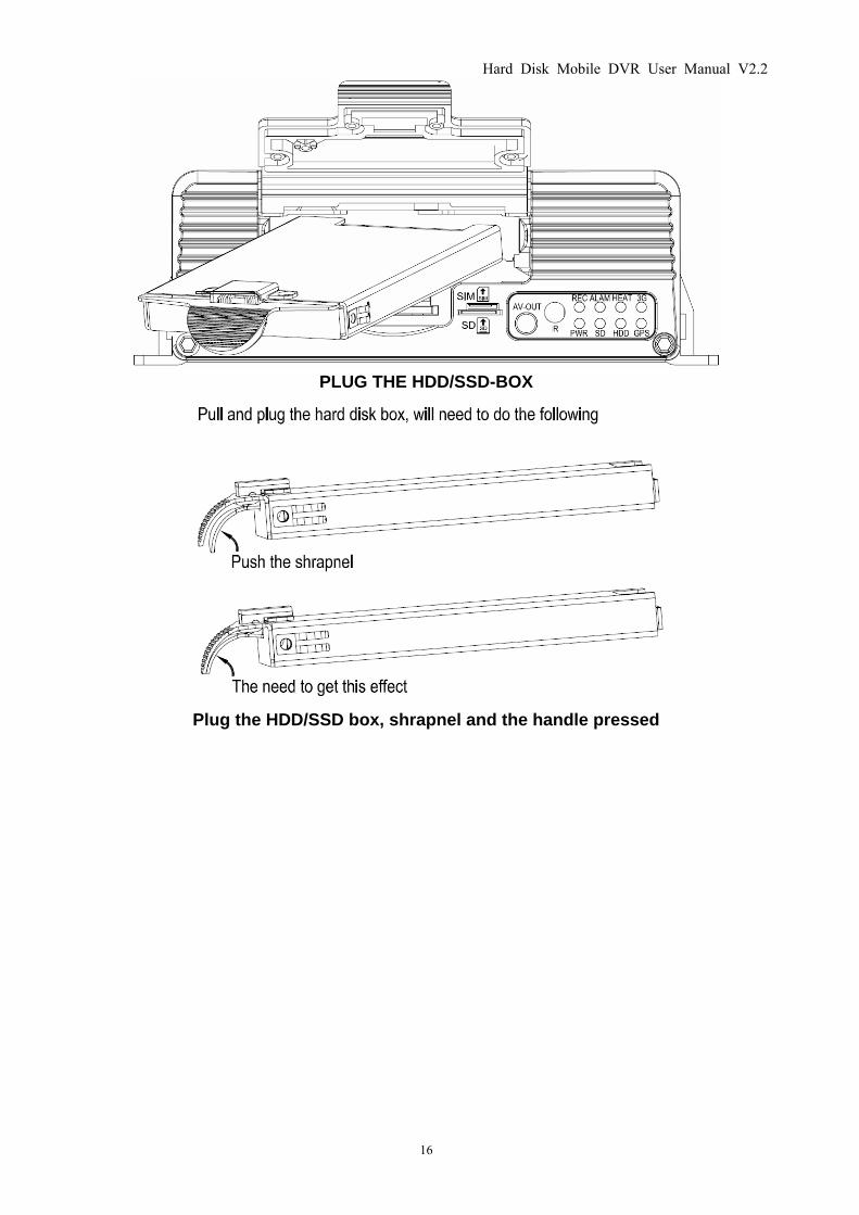
PLUG THE HDD/SSD-BOX
Plug the HDD/SSD box, shrapnel and the handle pressed
Hard Disk Mobile DVR User Manual V2.2
17
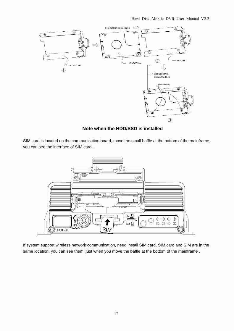
Note when the HDD/SSD is installed
SIM card is located on the communication board, move the small baffle at the bottom of the mainframe,
you can see the interface of SIM card .
If system support wireless network communication, need install SIM card. SIM card and SIM are in the
same location, you can see them, just when you move the baffle at the bottom of the mainframe .
Hard Disk Mobile DVR User Manual V2.2
18
3. Remote Control Function Instruction
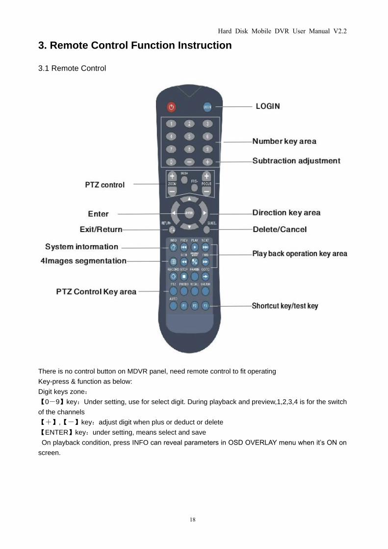
3.1 Remote Control
There is no control button on MDVR panel, need remote control to fit operating
Key-press & function as below:
Digit keys zone:
【0-9】key:Under setting, use for select digit. During playback and preview,1,2,3,4 is for the switch
of the channels
【+】,【-】key:adjust digit when plus or deduct or delete
【ENTER】key:under setting, means select and save
On playback condition, press INFO can reveal parameters in OSD OVERLAY menu when it’s ON on
screen.
Hard Disk Mobile DVR User Manual V2.2
19
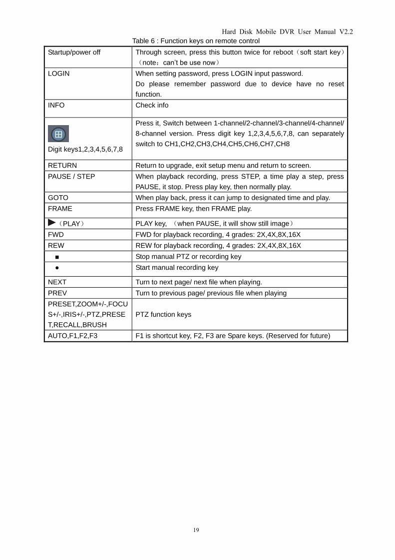
Table 6 : Function keys on remote control
Startup/power off Through screen, press this button twice for reboot(soft start key)
(note:can’t be use now)
LOGIN When setting password, press LOGIN input password.
Do please remember password due to device have no reset
function.
INFO Check info
Digit keys1,2,3,4,5,6,7,8
Press it, Switch between 1-channel/2-channel/3-channel/4-channel/
8-channel version. Press digit key 1,2,3,4,5,6,7,8, can separately
switch to CH1,CH2,CH3,CH4,CH5,CH6,CH7,CH8
RETURN Return to upgrade, exit setup menu and return to screen.
PAUSE / STEP When playback recording, press STEP, a time play a step, press
PAUSE, it stop. Press play key, then normally play.
GOTO When play back, press it can jump to designated time and play.
FRAME Press FRAME key, then FRAME play.
(PLAY) PLAY key, (when PAUSE, it will show still image)
FWD FWD for playback recording, 4 grades: 2X,4X,8X,16X
REW REW for playback recording, 4 grades: 2X,4X,8X,16X
■ Stop manual PTZ or recording key
● Start manual recording key
NEXT Turn to next page/ next file when playing.
PREV Turn to previous page/ previous file when playing
PRESET,ZOOM+/-,FOCU
S+/-,IRIS+/-,PTZ,PRESE
T,RECALL,BRUSH
PTZ function keys
AUTO,F1,F2,F3 F1 is shortcut key, F2, F3 are Spare keys. (Reserved for future)
Hard Disk Mobile DVR User Manual V2.2
20
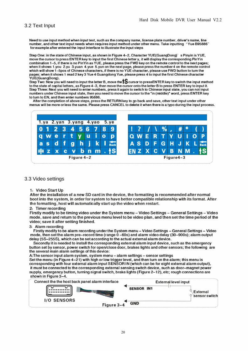
3.2 Text Input
3.3 Video settings
Hard Disk Mobile DVR User Manual V2.2
21
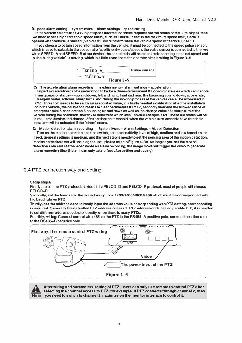
3.4 PTZ connection way and setting
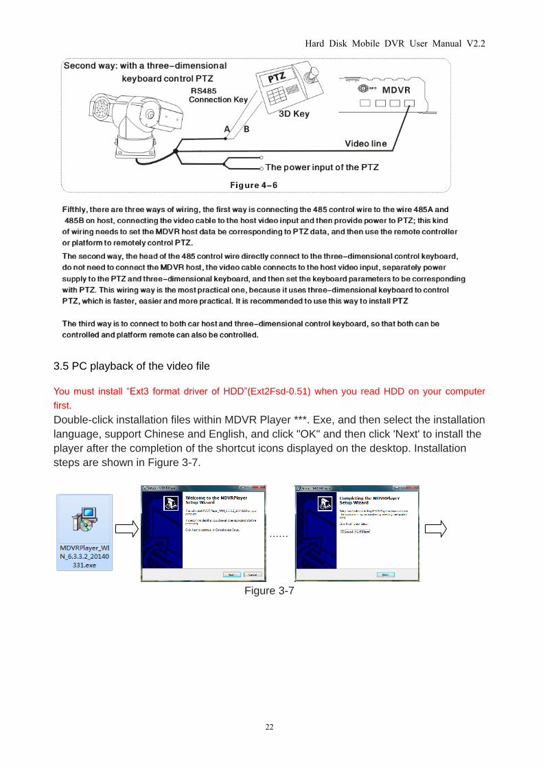
Hard Disk Mobile DVR User Manual V2.2
22
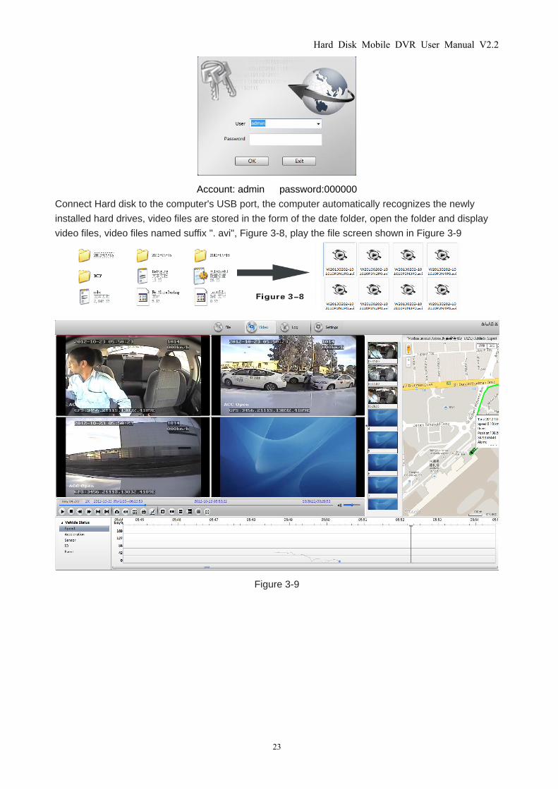
3.5 PC playback of the video file
You must install “Ext3 format driver of HDD”(Ext2Fsd-0.51) when you read HDD on your computer
first.
Double-click installation files within MDVR Player ***. Exe, and then select the installation
language, support Chinese and English, and click "OK" and then click 'Next' to install the
player after the completion of the shortcut icons displayed on the desktop. Installation
steps are shown in Figure 3-7.
……
Figure 3-7
Hard Disk Mobile DVR User Manual V2.2
23
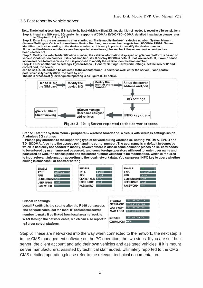
Account: admin password:000000
Connect Hard disk to the computer's USB port, the computer automatically recognizes the newly
installed hard drives, video files are stored in the form of the date folder, open the folder and display
video files, video files named suffix ". avi", Figure 3-8, play the file screen shown in Figure 3-9
Figure 3-9
Hard Disk Mobile DVR User Manual V2.2
24
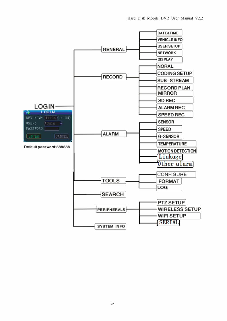
3.6 Fast report by vehicle server
Step 6: These are networked into the way when connected to the network, the next step is
in the CMS management software on the PC operation, the two steps: If you are self-built
server, the client account and add their own vehicles and assigned vehicles; If it is mount
server manufacturers, assisted by technical staff added. Ultimately reported to the CMS,
CMS detailed operation,please refer to the relevant technical documentation.
Hard Disk Mobile DVR User Manual V2.2
25
Hard Disk Mobile DVR User Manual V2.2
26
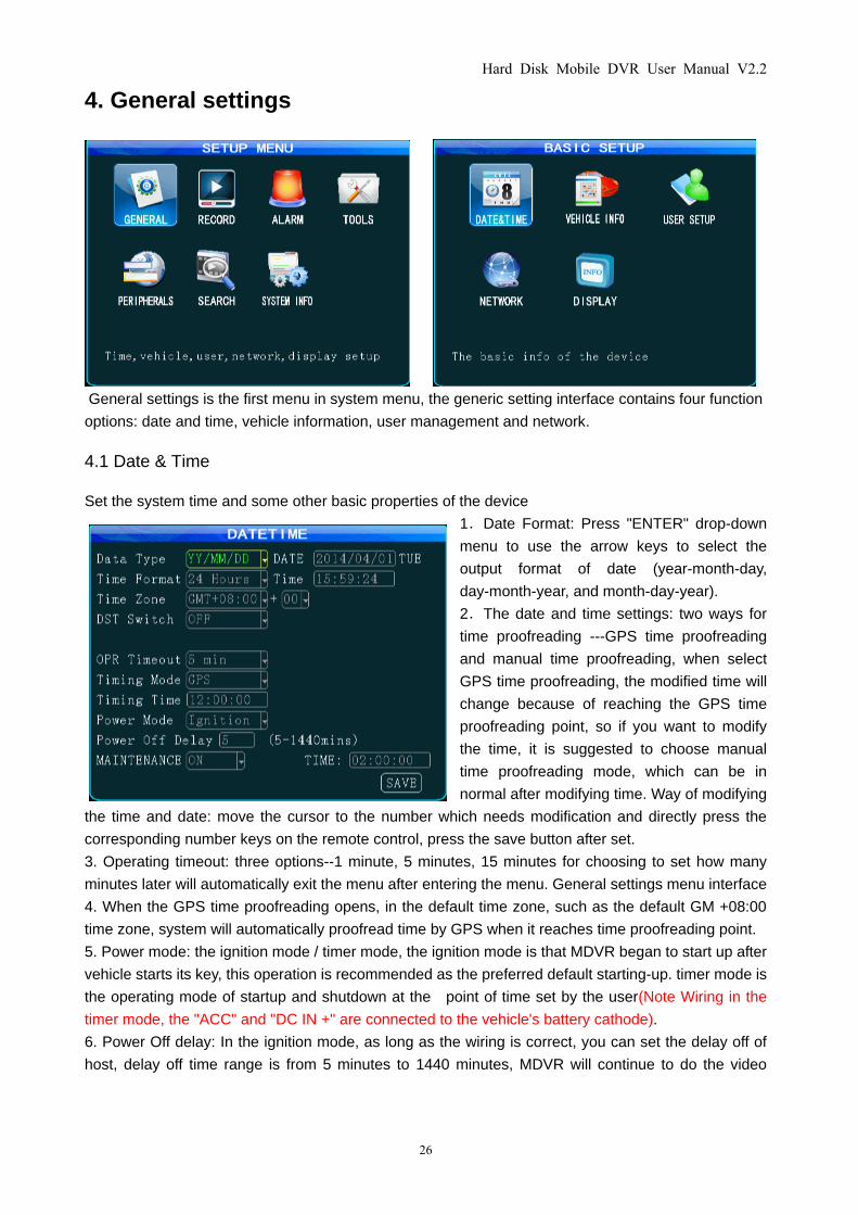
4. General settings
General settings is the first menu in system menu, the generic setting interface contains four function
options: date and time, vehicle information, user management and network.
4.1 Date & Time
Set the system time and some other basic properties of the device
1.Date Format: Press "ENTER" drop-down
menu to use the arrow keys to select the
output format of date (year-month-day,
day-month-year, and month-day-year).
2.The date and time settings: two ways for
time proofreading ---GPS time proofreading
and manual time proofreading, when select
GPS time proofreading, the modified time will
change because of reaching the GPS time
proofreading point, so if you want to modify
the time, it is suggested to choose manual
time proofreading mode, which can be in
normal after modifying time. Way of modifying
the time and date: move the cursor to the number which needs modification and directly press the
corresponding number keys on the remote control, press the save button after set.
3. Operating timeout: three options--1 minute, 5 minutes, 15 minutes for choosing to set how many
minutes later will automatically exit the menu after entering the menu. General settings menu interface
4. When the GPS time proofreading opens, in the default time zone, such as the default GM +08:00
time zone, system will automatically proofread time by GPS when it reaches time proofreading point.
5. Power mode: the ignition mode / timer mode, the ignition mode is that MDVR began to start up after
vehicle starts its key, this operation is recommended as the preferred default starting-up. timer mode is
the operating mode of startup and shutdown at the point of time set by the user(Note Wiring in the
timer mode, the "ACC" and "DC IN +" are connected to the vehicle's battery cathode).
6. Power Off delay: In the ignition mode, as long as the wiring is correct, you can set the delay off of
host, delay off time range is from 5 minutes to 1440 minutes, MDVR will continue to do the video
Hard Disk Mobile DVR User Manual V2.2
27
recording by the delay off set time before shutting down when the vehicle is turned off.
7. Auto Maintenance function: when the MDVR work more than 24hours. setup ON, give it a time,
MDVR will automatically restart to work properly, this need about 50 seconds.
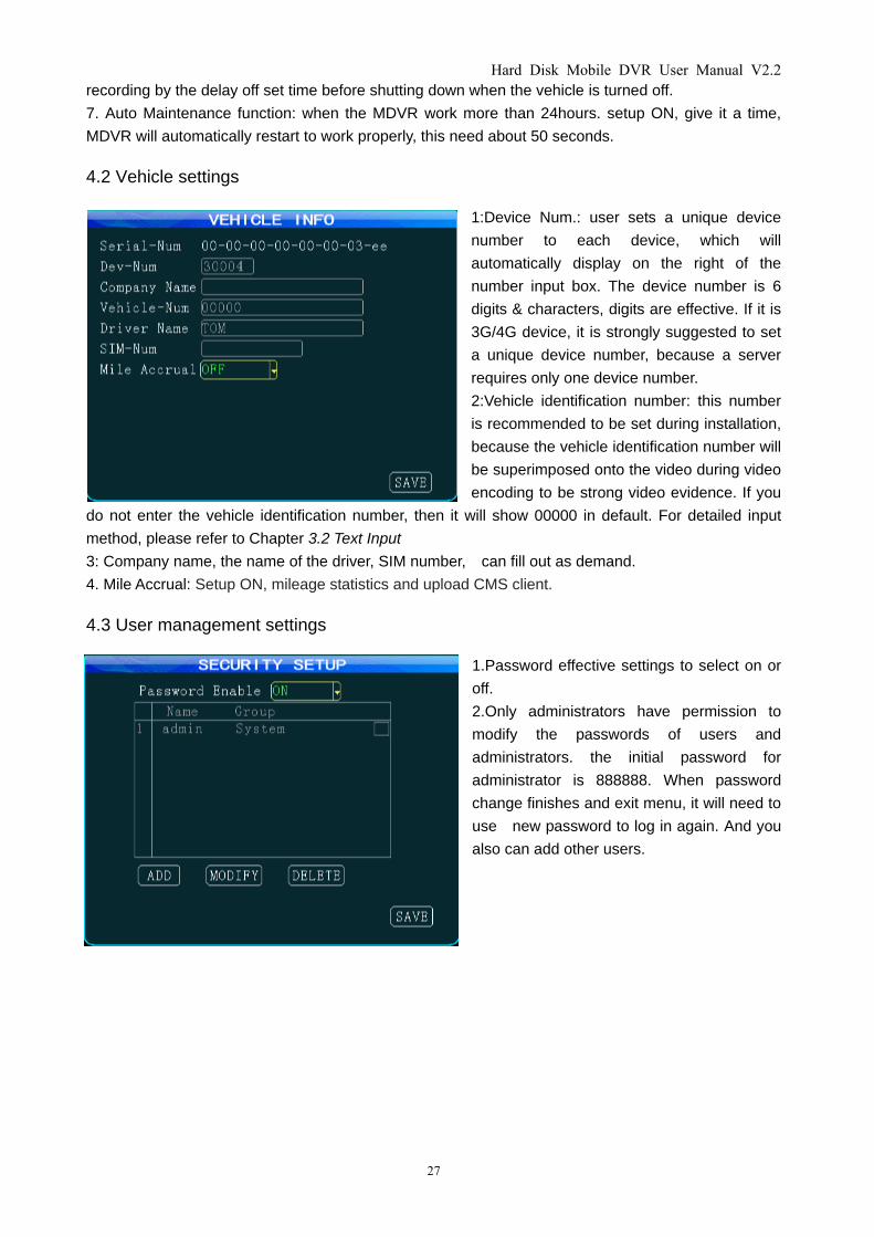
4.2 Vehicle settings
1:Device Num.: user sets a unique device
number to each device, which will
automatically display on the right of the
number input box. The device number is 6
digits & characters, digits are effective. If it is
3G/4G device, it is strongly suggested to set
a unique device number, because a server
requires only one device number.
2:Vehicle identification number: this number
is recommended to be set during installation,
because the vehicle identification number will
be superimposed onto the video during video
encoding to be strong video evidence. If you
do not enter the vehicle identification number, then it will show 00000 in default. For detailed input
method, please refer to Chapter 3.2 Text Input
3: Company name, the name of the driver, SIM number, can fill out as demand.
4. Mile Accrual: Setup ON, mileage statistics and upload CMS client.
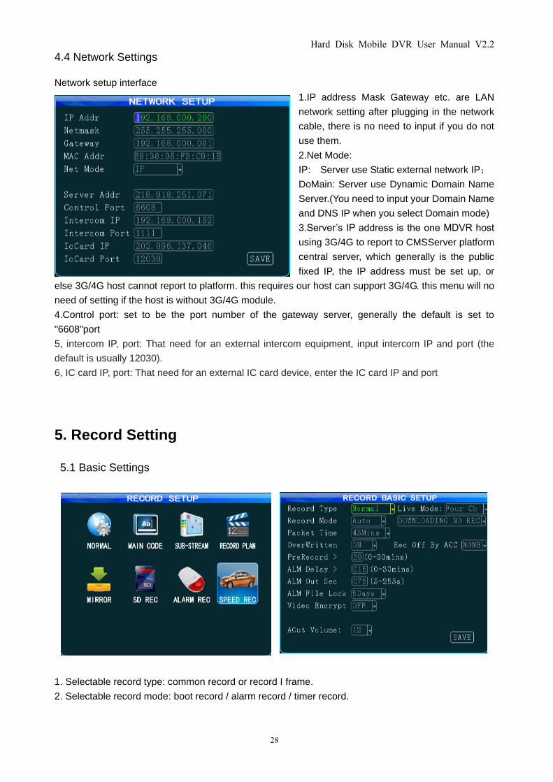
4.3 User management settings
1.Password effective settings to select on or
off.
2.Only administrators have permission to
modify the passwords of users and
administrators. the initial password for
administrator is 888888. When password
change finishes and exit menu, it will need to
use new password to log in again. And you
also can add other users.
Hard Disk Mobile DVR User Manual V2.2
28
4.4 Network Settings
Network setup interface
1.IP address Mask Gateway etc. are LAN
network setting after plugging in the network
cable, there is no need to input if you do not
use them.
2.Net Mode:
IP: Server use Static external network IP;
DoMain: Server use Dynamic Domain Name
Server.(You need to input your Domain Name
and DNS IP when you select Domain mode)
3.Server’s IP address is the one MDVR host
using 3G/4G to report to CMSServer platform
central server, which generally is the public
fixed IP, the IP address must be set up, or
else 3G/4G host cannot report to platform. this requires our host can support 3G/4G. this menu will no
need of setting if the host is without 3G/4G module.
4.Control port: set to be the port number of the gateway server, generally the default is set to
"6608"port
5, intercom IP, port: That need for an external intercom equipment, input intercom IP and port (the
default is usually 12030).
6, IC card IP, port: That need for an external IC card device, enter the IC card IP and port
5. Record Setting
5.1 Basic Settings
1. Selectable record type: common record or record I frame.
2. Selectable record mode: boot record / alarm record / timer record.
Hard Disk Mobile DVR User Manual V2.2
29
3. Selectable packet time: 15/30/45/60 minutes, which stands for the time period how long the video
file will become a packaged file.
4. Automatically overwritten can be selected to on / off, when on, the previous video files will be
automatically overwritten if the hard disk space is less than 2G as well as the mirror video disk & SD
card space is less than 300M,.
5. Alarm pre-record time: when alarm occurs, the recording before the alarm occurs will be packed to
be included into alarm record (range 0-30min).
6.Alarm recording delay: when alarm stops, the recording after the alarm stops will be packed to be
included into alarm record (range 0-30min) to form an alarm recording file.
7. Alarm out sec: when alarm occurs, the continuous output time of an alarm after connected to an
external alarm device, the output time (5S - 255S).
8. Alarm file lock time is the storage time for alarm video to be saved on the hard disk, the mirror disk,
SD card. in protected storage time, the alarm recording will not be overwritten even if the SD card is
full. there are optional 1/3/5/7/10/15/30/45 days under the drop-down menu, please set the
appropriate number of days according to the hard disk capacity.
9. Video encrypt: Video files can be encrypted, using the player on a PC requires a password when
playback.
10. Audio output volume:You can set the output volume.
11. Live mode: You can set the number of channels the boot screen.
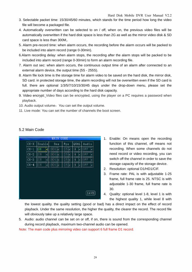
5.2 Main Code
1. Enable: On means open the recording
function of this channel, off means not
recording. When some channels do not
need record or video recording, you can
switch off the channel in order to save the
storage capacity of the storage device.
2. Resolution: optional D1/HD1/CIF.
3. Frame rate: PAL is with adjustable 1-25
frame, full frame rate is 25. NTSC is with
adjustable 1-30 frame, full frame rate is
30.
4. Quality: optional level 1-8, level 1 is with
the highest quality 1, while level 8 with
the lowest quality. the quality setting (good or bad) has a direct impact on the effect of record
playback. Under the same resolution, the higher the quality, the clearer the record. The record file
will obviously take up a relatively large space.
5. Audio: audio channel can be set on or off, if on, there is sound from the corresponding channel
during record playback, maximum two-channel audio can be opened.
Note: The main code plus mirroring video can support 6 full frame D1 record.
Hard Disk Mobile DVR User Manual V2.2
30
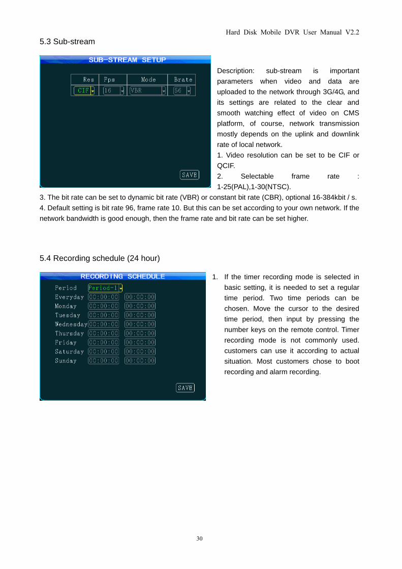
5.3 Sub-stream
Description: sub-stream is important
parameters when video and data are
uploaded to the network through 3G/4G, and
its settings are related to the clear and
smooth watching effect of video on CMS
platform, of course, network transmission
mostly depends on the uplink and downlink
rate of local network.
1. Video resolution can be set to be CIF or
QCIF.
2. Selectable frame rate :
1-25(PAL),1-30(NTSC).
3. The bit rate can be set to dynamic bit rate (VBR) or constant bit rate (CBR), optional 16-384kbit / s.
4. Default setting is bit rate 96, frame rate 10. But this can be set according to your own network. If the
network bandwidth is good enough, then the frame rate and bit rate can be set higher.
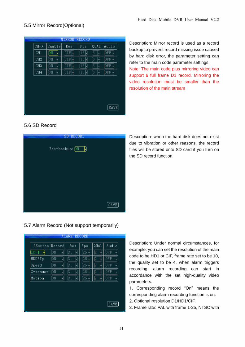
5.4 Recording schedule (24 hour)
1. If the timer recording mode is selected in
basic setting, it is needed to set a regular
time period. Two time periods can be
chosen. Move the cursor to the desired
time period, then input by pressing the
number keys on the remote control. Timer
recording mode is not commonly used.
customers can use it according to actual
situation. Most customers chose to boot
recording and alarm recording.
Hard Disk Mobile DVR User Manual V2.2
31
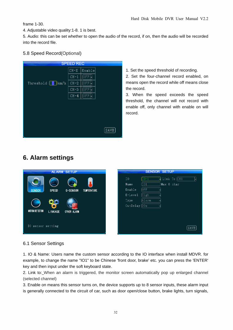
5.5 Mirror Record(Optional)
Description: Mirror record is used as a record
backup to prevent record missing issue caused
by hard disk error, the parameter setting can
refer to the main code parameter settings.
Note: The main code plus mirroring video can
support 6 full frame D1 record. Mirroring the
video resolution must be smaller than the
resolution of the main stream
5.6 SD Record
Description: when the hard disk does not exist
due to vibration or other reasons, the record
files will be stored onto SD card if you turn on
the SD record function.
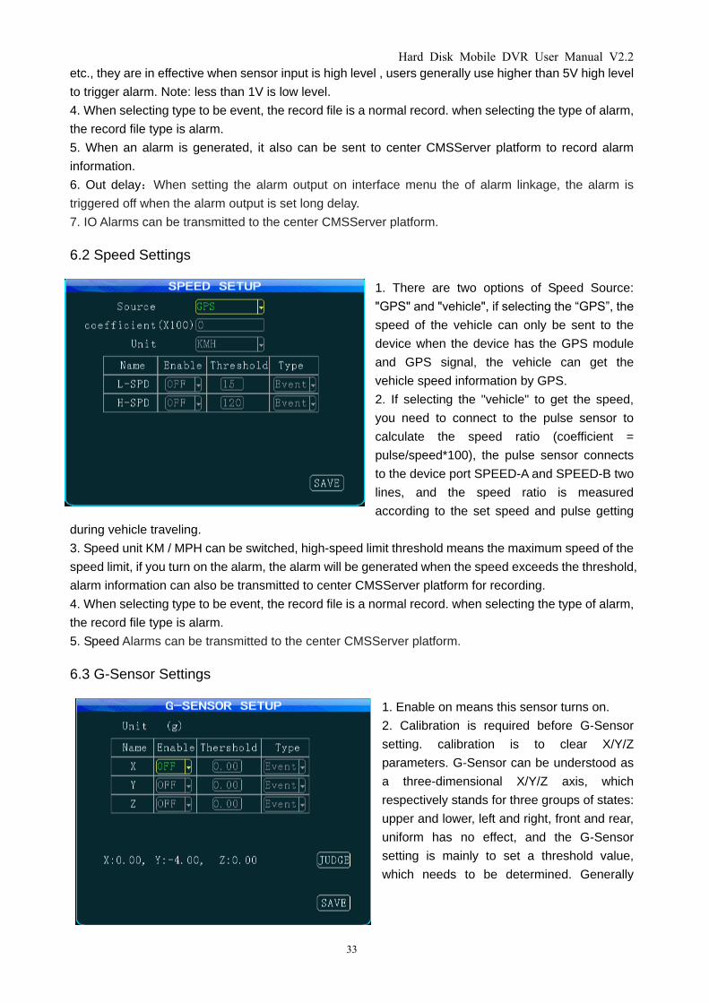
5.7 Alarm Record (Not support temporarily)
Description: Under normal circumstances, for
example: you can set the resolution of the main
code to be HD1 or CIF, frame rate set to be 10,
the quality set to be 4, when alarm triggers
recording, alarm recording can start in
accordance with the set high-quality video
parameters.
1. Corresponding record “On” means the
corresponding alarm recording function is on.
2. Optional resolution D1/HD1/CIF.
3. Frame rate: PAL with frame 1-25, NTSC with
Hard Disk Mobile DVR User Manual V2.2
32
frame 1-30.
4. Adjustable video quality:1-8. 1 is best.
5. Audio: this can be set whether to open the audio of the record, if on, then the audio will be recorded
into the record file.
5.8 Speed Record(Optional)
1. Set the speed threshold of recording.
2. Set the four-channel record enabled, on
means open the record while off means close
the record.
3. When the speed exceeds the speed
threshold, the channel will not record with
enable off, only channel with enable on will
record.
6. Alarm settings
6.1 Sensor Settings
1. IO & Name: Users name the custom sensor according to the IO interface when install MDVR. for
example, to change the name "IO1" to be Chinese 'front door, brake' etc. you can press the 'ENTER'
key and then input under the soft keyboard state.
2. Link to: When an alarm is triggered, the monitor screen automatically pop up enlarged channel
(selected channel)
3. Enable on means this sensor turns on, the device supports up to 8 sensor inputs, these alarm input
is generally connected to the circuit of car, such as door open/close button, brake lights, turn signals,
Hard Disk Mobile DVR User Manual V2.2
33
etc., they are in effective when sensor input is high level , users generally use higher than 5V high level
to trigger alarm. Note: less than 1V is low level.
4. When selecting type to be event, the record file is a normal record. when selecting the type of alarm,
the record file type is alarm.
5. When an alarm is generated, it also can be sent to center CMSServer platform to record alarm
information.
6. Out delay:When setting the alarm output on interface menu the of alarm linkage, the alarm is
triggered off when the alarm output is set long delay.
7. IO Alarms can be transmitted to the center CMSServer platform.
6.2 Speed Settings
1. There are two options of Speed Source:
"GPS" and "vehicle", if selecting the “GPS”, the
speed of the vehicle can only be sent to the
device when the device has the GPS module
and GPS signal, the vehicle can get the
vehicle speed information by GPS.
2. If selecting the "vehicle" to get the speed,
you need to connect to the pulse sensor to
calculate the speed ratio (coefficient =
pulse/speed*100), the pulse sensor connects
to the device port SPEED-A and SPEED-B two
lines, and the speed ratio is measured
according to the set speed and pulse getting
during vehicle traveling.
3. Speed unit KM / MPH can be switched, high-speed limit threshold means the maximum speed of the
speed limit, if you turn on the alarm, the alarm will be generated when the speed exceeds the threshold,
alarm information can also be transmitted to center CMSServer platform for recording.
4. When selecting type to be event, the record file is a normal record. when selecting the type of alarm,
the record file type is alarm.
5. Speed Alarms can be transmitted to the center CMSServer platform.
6.3 G-Sensor Settings
1. Enable on means this sensor turns on.
2. Calibration is required before G-Sensor
setting. calibration is to clear X/Y/Z
parameters. G-Sensor can be understood as
a three-dimensional X/Y/Z axis, which
respectively stands for three groups of states:
upper and lower, left and right, front and rear,
uniform has no effect, and the G-Sensor
setting is mainly to set a threshold value,
which needs to be determined. Generally
Hard Disk Mobile DVR User Manual V2.2
34
speaking vehicle’s instant acceleration is relatively large in case of slam the brakes on, crash,
acceleration and sharp turns, whose intuitive reflection is threshold beating, and PC displays X/Y/Z
three states by waveform when playing back. When an alarm is generated, it also can be sent to
center CMSServer platform to record alarm information.
3 When selecting type to be event, the record file is a normal record. when selecting the type of alarm,
the record file type is alarm.
4. Shocking Alarms can be transmitted to the center CMSServer platform.
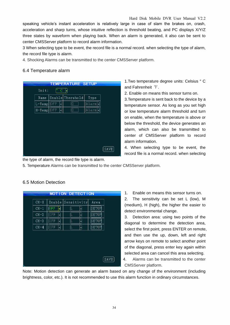
6.4 Temperature alarm
1.Two temperature degree units: Celsius ° C
and Fahrenheit ℉.
2. Enable on means this sensor turns on.
3.Temperature is sent back to the device by a
temperature sensor. As long as you set high
or low temperature alarm threshold and turn
on enable, when the temperature is above or
below the threshold, the device generates an
alarm, which can also be transmitted to
center of CMSServer platform to record
alarm information.
4. When selecting type to be event, the
record file is a normal record. when selecting
the type of alarm, the record file type is alarm.
5. Temperature Alarms can be transmitted to the center CMSServer platform.
6.5 Motion Detection
1. Enable on means this sensor turns on.
2. The sensitivity can be set L (low), M
(medium), H (high), the higher the easier to
detect environmental change.
3. Detection area: using two points of the
diagonal to determine the detection area,
select the first point, press ENTER on remote,
and then use the up, down, left and right
arrow keys on remote to select another point
of the diagonal, press enter key again within
selected area can cancel this area selecting.
4. Alarms can be transmitted to the center
CMSServer platform.
Note: Motion detection can generate an alarm based on any change of the environment (including
brightness, color, etc.). It is not recommended to use this alarm function in ordinary circumstances.
Hard Disk Mobile DVR User Manual V2.2
35
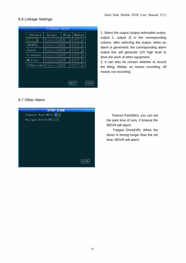
6.6 Linkage Settings
1. Select the output (output selectable output,
output 1, output 2) in the corresponding
column. after selecting the output, when an
alarm is generated, the corresponding alarm
output line will generate 12V high level to
drive the work of other equipment.
2. It can also be chosen whether to record
the Wlog, Wdata. on means recording, off
means not recording.
6.7 Other Alarm
Timeout Park(Min): you can set
the park time of cars, if timeout the
MDVR will alarm.
Fatigue Drive(HR): When the
driver is driving longer than the set
time, MDVR will alarm.
Hard Disk Mobile DVR User Manual V2.2
36
7. TOOLS
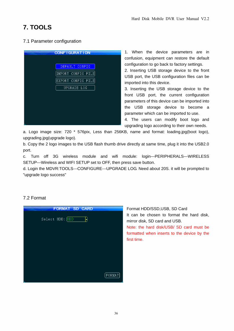
7.1 Parameter configuration
1. When the device parameters are in
confusion, equipment can restore the default
configuration to go back to factory settings.
2. Inserting USB storage device to the front
USB port, the USB configuration files can be
imported into this device.
3. Inserting the USB storage device to the
front USB port, the current configuration
parameters of this device can be imported into
the USB storage device to become a
parameter which can be imported to use.
4. The users can modify boot logo and
upgrading logo according to their own needs.
a. Logo image size: 720 * 576pix, Less than 256KB, name and format: loading.jpg(boot logo),
upgrading.jpg(upgrade logo).
b. Copy the 2 logo images to the USB flash thumb drive directly at same time, plug it into the USB2.0
port.
c. Turn off 3G wireless module and wifi module: login---PERIPHERALS---WIRELESS
SETUP---Wireless and WIFI SETUP set to OFF, then press save button.
d. Login the MDVR:TOOLS---CONFIGURE---UPGRADE LOG. Need about 20S. it will be prompted to
"upgrade logo success"
7.2 Format
Format HDD/SSD,USB, SD Card
It can be chosen to format the hard disk,
mirror disk, SD card and USB.
Note: the hard disk/USB/ SD card must be
formatted when inserts to the device by the
first time.
Hard Disk Mobile DVR User Manual V2.2
37
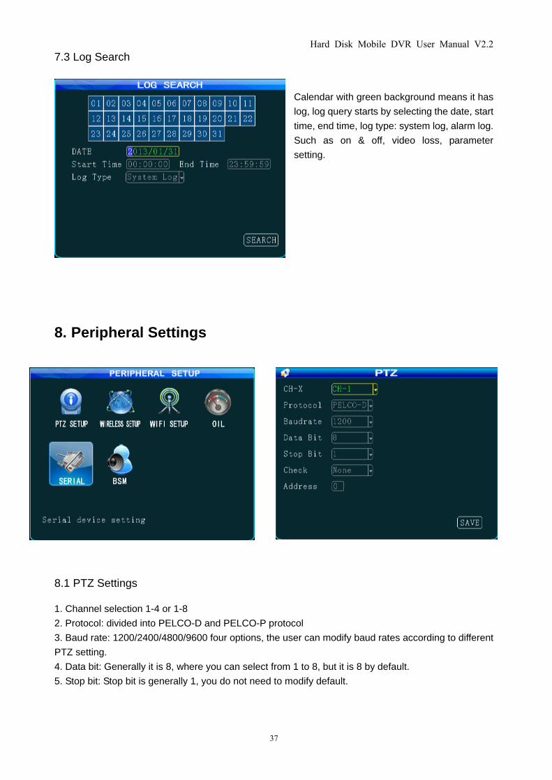
7.3 Log Search
Calendar with green background means it has
log, log query starts by selecting the date, start
time, end time, log type: system log, alarm log.
Such as on & off, video loss, parameter
setting.
8. Peripheral Settings
8.1 PTZ Settings
1. Channel selection 1-4 or 1-8
2. Protocol: divided into PELCO-D and PELCO-P protocol
3. Baud rate: 1200/2400/4800/9600 four options, the user can modify baud rates according to different
PTZ setting.
4. Data bit: Generally it is 8, where you can select from 1 to 8, but it is 8 by default.
5. Stop bit: Stop bit is generally 1, you do not need to modify default.
Hard Disk Mobile DVR User Manual V2.2
38
6 Check: check bit is to select the check way. Generally it is chosen to be None.
7 Address: the address code is input directly by the address corresponding to PTZ setting, they must
be setting corresponding to, the default address code of most PTZ is 1. PTZ has adjustable address
code DIP, and it is needed to set different address codes to identify when there are numbers of PTZ.
8. Wiring method: PTZ cathode connected to RS485-A, negative connected to RS485-B.
When PTZ relevant parameters are set ready, the remote control can only be used to control PTZ after
the channel connected to PTZ is selected, for example, PTZ is connected to Channel 2, then you can
only control it by switching to 2-channel to maximize it on the monitor interface.
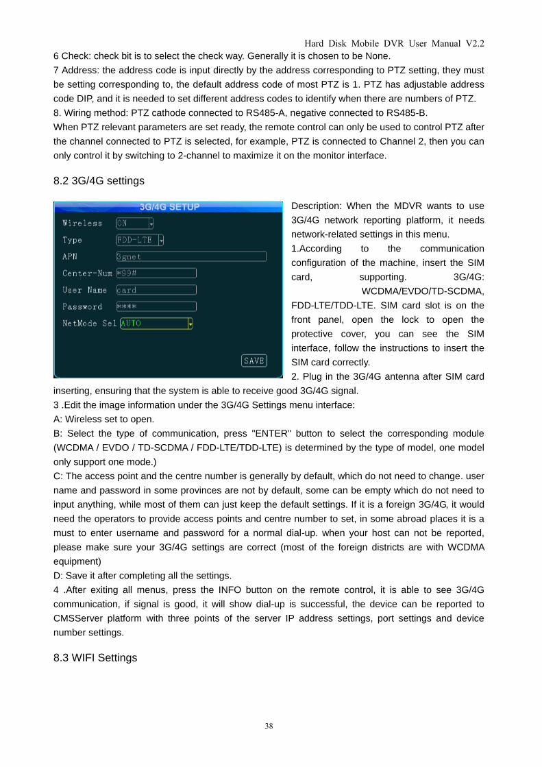
8.2 3G/4G settings
Description: When the MDVR wants to use
3G/4G network reporting platform, it needs
network-related settings in this menu.
1.According to the communication
configuration of the machine, insert the SIM
card, supporting. 3G/4G:
WCDMA/EVDO/TD-SCDMA,
FDD-LTE/TDD-LTE. SIM card slot is on the
front panel, open the lock to open the
protective cover, you can see the SIM
interface, follow the instructions to insert the
SIM card correctly.
2. Plug in the 3G/4G antenna after SIM card
inserting, ensuring that the system is able to receive good 3G/4G signal.
3 .Edit the image information under the 3G/4G Settings menu interface:
A: Wireless set to open.
B: Select the type of communication, press "ENTER" button to select the corresponding module
(WCDMA / EVDO / TD-SCDMA / FDD-LTE/TDD-LTE) is determined by the type of model, one model
only support one mode.)
C: The access point and the centre number is generally by default, which do not need to change. user
name and password in some provinces are not by default, some can be empty which do not need to
input anything, while most of them can just keep the default settings. If it is a foreign 3G/4G, it would
need the operators to provide access points and centre number to set, in some abroad places it is a
must to enter username and password for a normal dial-up. when your host can not be reported,
please make sure your 3G/4G settings are correct (most of the foreign districts are with WCDMA
equipment)
D: Save it after completing all the settings.
4 .After exiting all menus, press the INFO button on the remote control, it is able to see 3G/4G
communication, if signal is good, it will show dial-up is successful, the device can be reported to
CMSServer platform with three points of the server IP address settings, port settings and device
number settings.
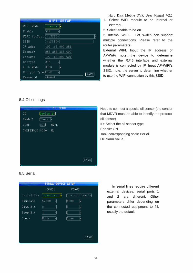
8.3 WIFI Settings
Hard Disk Mobile DVR User Manual V2.2
39
1. Select WIFI module to be internal or
external.
2. Select enable to be on.
3. Internal WIFI: Hot switch can support
multiple connections. Please refer to the
router parameters.
External WIFI. Input the IP address of
AP-WiFi, note: the device to determine
whether the RJ45 interface and external
module is connected by IP. Input AP-WIFI's
SSID, note: the server to determine whether
to use the WIFI connection by this SSID.
8.4 Oil settings
Need to connect a special oil sensor.(the sensor
that MDVR must be able to identify the protocol
oil sensor)
ID: Select the oil sensor type.
Enable: ON
Tank corresponding scale Per oil
Oil alarm Value.
8.5 Serial
In serial lines require different
external devices, serial ports 1
and 2 are different. Other
parameters differ depending on
the connected equipment to fill,
usually the default
Hard Disk Mobile DVR User Manual V2.2
40
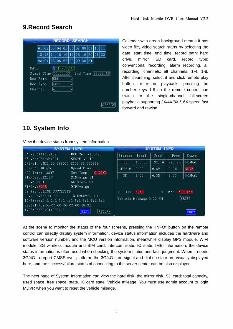
9.Record Search
Calendar with green background means it has
video file, video search starts by selecting the
date, start time, end time, record path: hard
drive, mirror, SD card, record type:
conventional recording, alarm recording, all
recording, channels: all channels, 1-4, 1-8.
After searching, select it and click remote play
button for record playback,. pressing the
number keys 1-8 on the remote control can
switch to the single-channel full-screen
playback, supporting 2X/4X/8X /16X speed fast
forward and rewind.
10. System Info
View the device status from system information
At the scene to monitor the status of the four screens, pressing the "INFO" button on the remote
control can directly display system information, device status information includes the hardware and
software version number, and the MCU version information, meanwhile display GPS module, WIFI
module, 3G wireless module and SIM card, intercom state, IO state, IMEI information, the device
status information is often used when checking the system status and fault judgment. When it needs
3G/4G to report CMSServer platform, the 3G/4G card signal and dial-up state are visually displayed
here, and the success/failure status of connecting to the server center can be also displayed.
The next page of System Information can view the hard disk, the mirror disk, SD card: total capacity,
used space, free space, state. IC card state. Vehicle mileage. You must use admin account to login
MDVR when you want to reset the vehicle mileage.
Hard Disk Mobile DVR User Manual V2.2
41
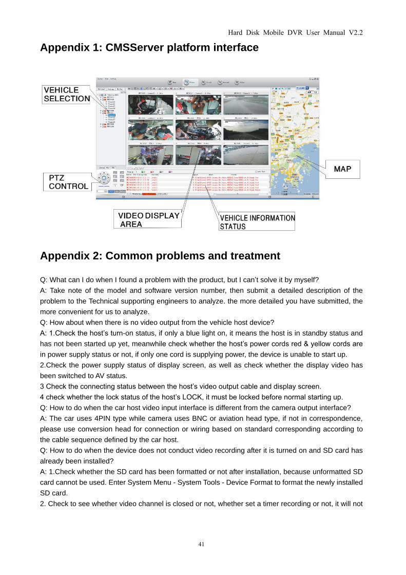
Appendix 1: CMSServer platform interface
Appendix 2: Common problems and treatment
Q: What can I do when I found a problem with the product, but I can’t solve it by myself?
A: Take note of the model and software version number, then submit a detailed description of the
problem to the Technical supporting engineers to analyze. the more detailed you have submitted, the
more convenient for us to analyze.
Q: How about when there is no video output from the vehicle host device?
A: 1.Check the host’s turn-on status, if only a blue light on, it means the host is in standby status and
has not been started up yet, meanwhile check whether the host’s power cords red & yellow cords are
in power supply status or not, if only one cord is supplying power, the device is unable to start up.
2.Check the power supply status of display screen, as well as check whether the display video has
been switched to AV status.
3 Check the connecting status between the host’s video output cable and display screen.
4 check whether the lock status of the host’s LOCK, it must be locked before normal starting up.
Q: How to do when the car host video input interface is different from the camera output interface?
A: The car uses 4PIN type while camera uses BNC or aviation head type, if not in correspondence,
please use conversion head for connection or wiring based on standard corresponding according to
the cable sequence defined by the car host.
Q: How to do when the device does not conduct video recording after it is turned on and SD card has
already been installed?
A: 1.Check whether the SD card has been formatted or not after installation, because unformatted SD
card cannot be used. Enter System Menu - System Tools - Device Format to format the newly installed
SD card.
2. Check to see whether video channel is closed or not, whether set a timer recording or not, it will not
Hard Disk Mobile DVR User Manual V2.2
42
take video when it is not within the video recording time period.
3.Check the SD card inserting status and whether the SD light on front panel is on or not.
Q: The video file is missing or there is no video file within a certain period of time, how to do?
A: 1. Determine the time period by analyzing the final video file before missing and the first video
file after recovery.
2. Confirm whether the host is not on during that period of time, such as when the driver halfway
parking, loading and unloading goods while the host is not set by video delay.
Q: When car PTZ cannot be controlled, it cannot rotate up and down, how to do?
A: Check whether PTZ protocols and baud rate are set correct, address codes are corresponding or
not, whether have selected to maximize the video of the channel when control the PTZ, for example,
when control the second channel, it must maximize the screen of the second channel image to control
it.
GPS-related issues
Q: GPS module exists but no coordinate information?
A: 1.Check whether GPS module exists, if it does not exist, check whether the hardware is installed or
in a good contact.
2.Make sure that the GPS antenna contacts are good, whether the antenna is broken, it is
recommended to be located in places with strong signal, note that some car glass shielding film will
block GPS signals.
3 If the test is in the room, the signal of GPS antenna in the room will be obscured, it is recommended
that the GPS antenna is placed outdoor.
Q: Deviation of GPS location on map?
A: It means the signal is valid if the GPS module already positioned, there may many reasons for the
deviation, such as government restrictions, permissible error, GPS signal interruption, etc. the actual
satellite map may have deviation for security reasons, general map can solve the problem by using
GPS correction.
3G wireless module
Q: If use the 3G/4G wireless module for dial-up, what do I need to pay attention to?
A: 1. Choose the built-in wireless module WCDMA / EVDO / TD-SCDMA / FDD-LTE/TDD-LTE,
corresponding module settings are not the same, the modules supported by different machines models
are not the same, so please make sure whether your module and SIM is in correspondence. Do not
use EVDO SIM card on WCDMA machine.
2.Check whether the settings of Server IP and port are correct, whether 3G/4G signal is strong enough
for dialing, and then check whether the 3G/4G dial-up is successful or not.
3. When dialing is unsuccessful, please check 3G/4G antenna is in good contact or not, the dial up
may fail because of weak signal, moreover, please check whether the SIM card has enough traffic, if
no traffic, dial-up will be unsuccessful.
Q: When 3G/4G has neither report nor video , what should be done first?
A: Press INFO key to enter the system information page, check whether the SIM card exists and view
the signal strength as well as dial-up status, whether the antenna is in good contact, and then check
the SIM to see whether it is out of traffic, the most basic judgment is to replace the SIM card. If the dial
up failed with signal, then check whether the settings of center number and the port are correct.
Moreover check whether the device number of the product is already occupied.
Q: 3G/4G signal is intermittent, video is jammed?
A: At present the signal coverage of WCDMA / EVDO / TD-SCDMA / FDD-LTE/TDD-LTE is rather wide,
Hard Disk Mobile DVR User Manual V2.2
43
however, there are some mountainous districts without signal coverage, and some suburban areas
have weak signal due to the local network constraints, then it will be jammed during watching of video,
or video cannot be watched at all, the greatest impact of this situation is from the local network.
Moreover check whether the frame rate setting of sub-stream is too high, because the video may also
occur such situation when the network is poor and frame rate setting is high.
Q: Why the vehicle and video cannot be seen in CMSServer client when the device has been started?
A: At first make sure the central registration server is switched on and on the net, then check whether
the host device number has been occupied to cause conflict, secondly check whether the settings of
server-centric IP and port are correct. devices report to the center via the built-in 3G/4G module or via
WIFI. If via built-in 3G/4G, please check whether selected the correct type of built-in 3G/4G module, for
example, WCDMA and EVDO module needs the support from corresponding SIM card, check whether
the antenna is in good contact. If it still can not report when above all are checked, enter into the
system information page to view dial-up. If dial-up is not successful, look up whether the setting of data
access point and center number is correct. If all ultimately fail, please collect as much information as
possible to submit to the technical supporting staff for analysis, the more data provided, the more
convenient for technicians to solve the problem.
Q: The device is online, but why can I not see the video image?
A: Please set lower sub-stream to transmit image, the blocked or slow transmission speed situation
may occur when the sub-stream frame rate is set very high and be affected by network uploading limit.
poor network signal or intermittent will seriously affect the video transmission.
Q: The device is properly reported on CMSServer, but the videos cannot be seen after using for some
time?
A: Firstly check whether the host side displays dialing, if it keeps the dialing status, it may be because
the flow of the SIM card has run out, replace the SIM card to test. Secondly query whether the
host device number has been modified by the driver, the host with modified device number needs
to be resubmitted to add vehicle information. thirdly, if it still does not work by changing the card, it
will need to check whether the host's 3G/4G module fails.
Hard Disk Mobile DVR User Manual V2.2
44
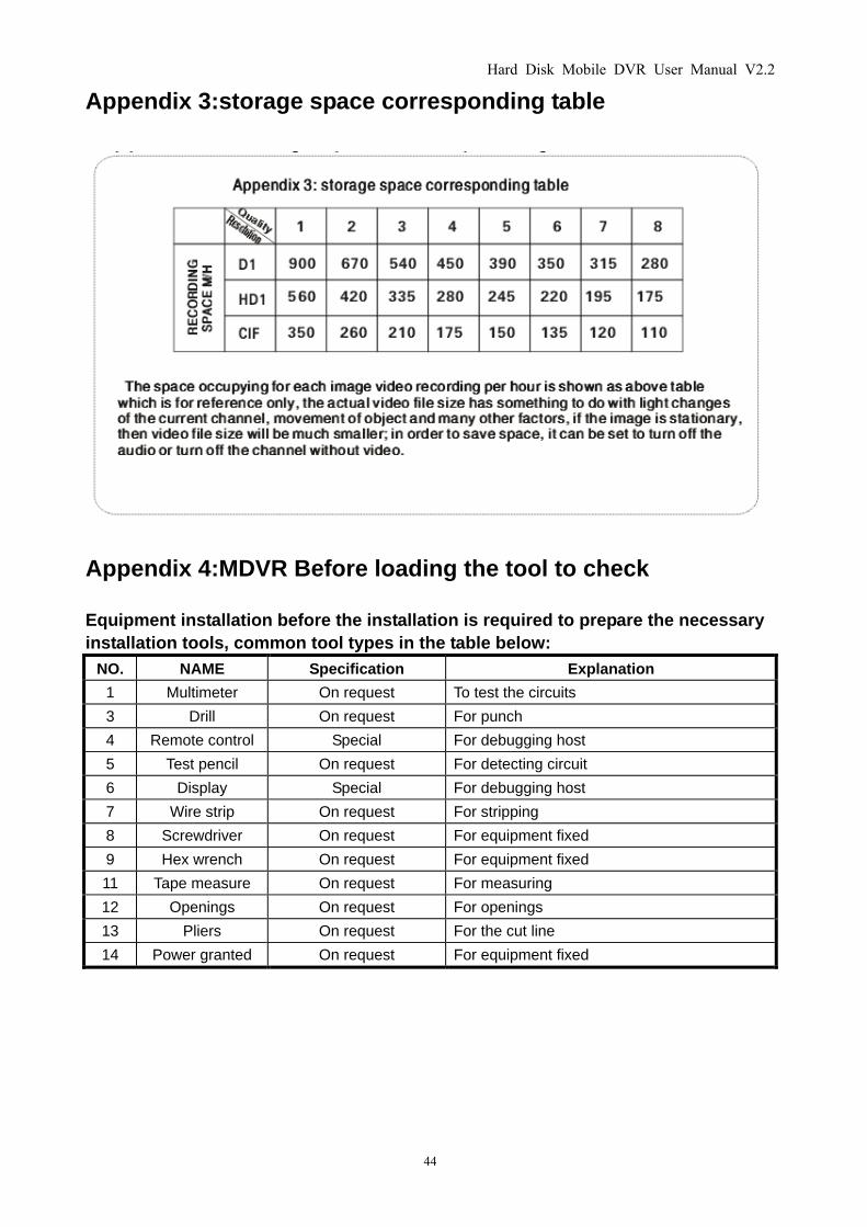
Appendix 3:storage space corresponding table
Appendix 4:MDVR Before loading the tool to check
Equipment installation before the installation is required to prepare the necessary
installation tools, common tool types in the table below:
NO. NAME Specification Explanation
1 Multimeter On request To test the circuits
3 Drill On request For punch
4 Remote control Special For debugging host
5 Test pencil On request For detecting circuit
6 Display Special For debugging host
7 Wire strip On request For stripping
8 Screwdriver On request For equipment fixed
9 Hex wrench On request For equipment fixed
11 Tape measure On request For measuring
12 Openings On request For openings
13 Pliers On request For the cut line
14 Power granted On request For equipment fixed
Hard Disk Mobile DVR User Manual V2.2
45
Appendix 5:MDVR Before loading the installation of auxiliary
examination
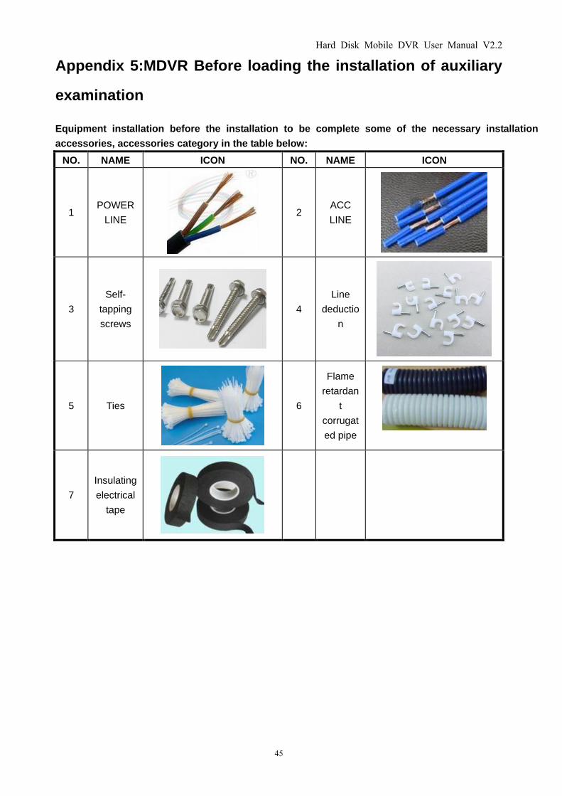
Equipment installation before the installation to be complete some of the necessary installation
accessories, accessories category in the table below:
NO. NAME ICON NO. NAME ICON
1 POWER
LINE
2 ACC
LINE
3
Self-
tapping
screws
4
Line
deductio
n
5 Ties
6
Flame
retardan
t
corrugat
ed pipe
7
Insulating
electrical
tape