gpu accelerated direct volume rendering on an interactive ... · agus et al. / gpu accelerated...
TRANSCRIPT

EUROGRAPHICS 2008 / G. Drettakis and R. Scopigno(Guest Editors)
Volume 27 (2008), Number 2
GPU Accelerated Direct Volume Rendering on an Interactive
Light Field Display
Marco Agus, Enrico Gobbetti, José Antonio Iglesias Guitián, Fabio Marton, Giovanni Pintore
Visual Computing Group, CRS4, Pula, Italy – http://www.crs4.it/vic/
Abstract
We present a GPU accelerated volume ray casting system interactively driving a multi-user light field display.
The display, driven by a single programmable GPU, is based on a specially arranged array of projectors and
a holographic screen and provides full horizontal parallax. The characteristics of the display are exploited to
develop a specialized volume rendering technique able to provide multiple freely moving naked-eye viewers the
illusion of seeing and manipulating virtual volumetric objects floating in the display workspace. In our approach,
a GPU ray-caster follows rays generated by a multiple-center-of-projection technique while sampling pre-filtered
versions of the dataset at resolutions that match the varying spatial accuracy of the display. The method achieves
interactive performance and provides rapid visual understanding of complex volumetric data sets even when using
depth oblivious compositing techniques.
Categories and Subject Descriptors (according to ACM CCS): B.4.2 [Input/Output and Data Communications]: In-put/Output Devices Image Display I.3.3 [Computer Graphics]: Picture/Image Generation I.3.7 [Computer Graph-ics]: Three-dimensional graphics and realism
1. Introduction
The rapid development of programmable graphics hardwareis making it possible to interactively render volumes withhigh visual fidelity on commodity PCs. Resolving the spa-tial arrangement of complex three-dimensional structures inimages produced by such techniques is however often a diffi-cult task. In particular, medical data produced by CT or MRIscans often contain many overlapping structures, leading tocluttered images which are difficult to understand. Enhanc-ing depth and shape perception in volumetric rendering isthus a very active research area, which is tackled under dif-ferent angles. Recent contributions include methods for sup-porting real-time rendering and user interaction, improvingrendering quality with advanced photorealistic models, e.g.,including specular reflections and shadows, or developingnon-photorealistic approaches to emphasize model featuresby illustrative techniques, e.g, vicinity shading, edge detec-tion, halos, or cutaways. An orthogonal research directionconsists of improving volumetric understanding by present-ing results on displays able to elicit more depth cues than theconventional 2D monitor or providing improved color repro-duction. For instance, Ghosh et al [GTH05] have shown howa high dynamic range display can substantially improve vol-ume understanding through perceptually optimized transfer
functions. In this work, we focus on enhancing spatial under-standing of 3D data through perceptual cues for accommo-dation, stereo and motion parallax delivered by a light fielddisplay, i.e., a display supporting high resolution directionselective light emission. This direction looks very promising,since there is evidence that ego- and/or model-motion as wellas stereopsis are essential cues to achieve rapid direct percep-tion of volumetric data [BBD∗07, ME04]. Recent advancesin 3D display design demonstrate that high resolution displaytechnology able to reproduce natural light fields is practicallyachievable [BFA∗05, JMY∗07]. Rendering for such displaysrequires generating a large number of light beams of appro-priate origin, direction, and color, which is a complex andcomputationally intensive task. Moreover, the displays opti-cal characteristics impose specialized rendering methods.
In this article, we present and demonstrate a GPU acceler-ated volume ray casting system interactively driving a multi-user light field display based on projection technology. Thedisplay, driven by a single programmable GPU through a DVIlink, is based on a specially arranged projector array placedbehind an anisotropic holographic screen. This setup pro-vides full continuous horizontal parallax in a sizeable zone infront of the screen. The restriction to horizontal parallax re-duces light field complexity, making the real-time rendering
c© 2008 The Author(s)Journal compilation c© 2008 The Eurographics Association and Blackwell Publishing Ltd.Published by Blackwell Publishing, 9600 Garsington Road, Oxford OX4 2DQ, UK and350 Main Street, Malden, MA 02148, USA.

Agus et al. / GPU Accelerated Direct Volume Rendering on an Interactive Light Field Display
Figure 1: Volume ray casting of the Chameleon dataset. Images of the light field display taken with a hand held video camera
moving in the display workspace. Note the parallax effects and the view-dependent illumination effects.
problem more tractable. The characteristics of the display areexploited by a specialized rendering technique able to pro-vide multiple freely moving naked-eye viewers the illusionof seeing virtual volumetric objects floating at fixed physi-cal locations in the display workspace (see figure 1). Centralto our approach is a GPU ray-caster that follows rays gen-erated by a multiple-center-of-projection (MCOP) technique,while sampling pre-filtered versions of the dataset at resolu-tions that match the varying spatial accuracy of the display.Our main contributions thus include:
• a general MCOP technique for producing perspective cor-rect images on a class of horizontal parallax only light fielddisplays based on anisotropic diffusers; the solution pro-vides a correct solution for viewers at a known distanceand height from the screen and a good approximation forall other positions;
• a GPU accelerated framework implementing volume ray-casting on a light field display using a combination of ver-tex and fragment shaders;
• the description and demonstration of a prototype hard-ware/software system achieving interactive performanceon non-trivial datasets on a single PC configuration;
Although not all the techniques presented here are novelin themselves, their elaboration and combination in a singlesystem is non trivial and represents a substantial enhancementto the state-of-the-art.
2. Related work
Interactive 3D display technology. A huge number of ap-proaches have been proposed to support naked-eye multi-scopic visualization, and a full review of the subject is outof scope for this paper. We provide here only a rapid surveyof the subject, with a particular emphasis on the most closelyrelated approaches. For a good review on the subject we referthe reader to [Dod05]. The key technical feature characteriz-ing 3D displays is direction-selective light emission, whichis obtained most commonly by volumetric, holographic, ormulti-view approaches. Volumetric displays synthesize lightfields by projecting light beams on refractive/reflective me-dia positioned or moved in space (e.g., [MMMR00,FDHN01,
RS00]). Commercial displays are readily available (e.g., fromActuality Systems). The main disadvantages are the limitedscalability of the approach, and the difficulty in presentingocclusion effects. The latter problem has been recently solvedin the displays presented by [JMY∗07] and [CNH∗07],which employ an anisotropic diffuser covering a rapidly spin-ning mirror illuminated by a single high speed video projec-tor synchronized with mirror rotation. Such a setup allowsfor 360◦ viewing, but, because of mechanical constraints, ispractical only for limited image sizes and model complexity.Pure holographic techniques are based on generating holo-graphic patterns to reconstruct the light wavefront originat-ing from the displayed object, e.g., using acousto-optic ma-terials [SHLS∗95], optically addressed spatial light modula-tors [SCC∗00], or digital micro-mirror devices [HMG03].Although this approach can theoretically provide the mostcompelling imagery, the principle itself imposes limitationson realistically achievable image sizes, resolution, speckle,with consequent narrow fields of view, alongside enormouscomputing capacity required to reach acceptable refresh ratesfor true interaction. In current prototypes, still confined inresearch labs, the display hardware is very large in relationto the size of the image (which is typically a few centime-ters in each dimension). Typical multi-view displays, oftenbased on an optical mask or a lenticular lens array, showmultiple 2D images in multiple zones in space. They sup-port multiple simultaneous viewers, but at the cost of restrict-ing them to be within a limited viewing angle. Multi-viewdisplays are often based on an optical mask or a lenticu-lar lens array. Optical masks introduce significant light losswhen there are more than two views. Moreover, the barrierstructure becomes visible as the number of views increases.On the other hand, lenticular displays magnify the pixel ma-trix of the projecting devices creating dark zones betweenviewing slots. The Cambridge multi-view display is a clas-sic design in this area [DML∗00], and a number of manufac-turers (Philips [vPF96], Sharp [WHJ∗00], Opticality [RR05],Samsung, Stereographics, Zeiss) produce monitors based onvariations of this technology. Typical state-of-the-art displaystypically use 8–10 images, i.e., directions, at the expenseof resolution. Matusik et al. [MP04] demonstrated a proto-
c© 2008 The Author(s)Journal compilation c© 2008 The Eurographics Association and Blackwell Publishing Ltd.
Agus et al. / GPU Accelerated Direct Volume Rendering on an Interactive Light Field Display
type based on this technology and assembled with sixteen1024x768 projectors and a lenticular screen. As in our case,the setup requires one projector per view. However, theirscreen achieves vertical diffusion not by diffusing light verti-cally from the screen as in our display, but by focusing lighthorizontally onto a diffuse surface, yielding a different pro-jection geometry. A 3D stereo effect is obtained when theleft eye and the right eye see different but matching informa-tion. The small number of views of multi-view systems basedon masks or lenticulars produces, however, cross-talks anddiscontinuities upon viewer’s motion [Dod96]. The displayused in this work [BFA∗05], produced by the Holografikacompany, uses the distributed image generation approach ofprojector-based multi-view technology, but removes some ofthe intrinsic optical limitations, as it offers a fully continuousblend among views thanks to the light shaping capabilitiesof a holographically recorded screen. One limitation of most3D display solutions, also shared by the display used in thiswork, is that only horizontal parallax is provided. Yang etal. [YHLJ06] presented an improved system based on a clus-ter of projectors that provides parallax both horizontally andvertically. This solution provides a more faithful light fieldreconstruction but requires the generation of a much largernumber of rays to achieve the same spatial accuracy, whichmakes it currently practical only for very small image areasor narrow fields of views.
Projecting graphics to the 3D display. The image genera-tion methods employed in conjunction with 3D displays musttake into account the display characteristics both in terms ofgeometry and resolution of the reproduced light fields. In ourwork, we employ a multiple-center-of-projection techniqueto produce images that exhibit correct stereo and motionparallax cues. Our projection algorithm relates to previouswork in light field rendering and holography. The multiple-viewpoint-rendering approach [Hal98] harnesses perspectivecoherence to improve the efficiency of rendering multipleperspective image sequences. Halle et al. [HBKU91] pro-posed a method where static holographic stereograms ac-count for the viewer’s distance but not their height. The lightfield display recently presented by Jones et al. [JMY∗07]also uses a MCOP approach, similar to ours, but their dis-play geometry is radically different. Previous work in render-ing for light field displays have used, typically, standard or-thographic or perspective projections [RWC∗98, CNH∗07].This approach simplifies rendering using a fixed functiongraphics pipeline but produces perspective distortions whenapplied to displays based on anisotropic light shaping ele-ments [JMY∗07]. None of these works takes into account thefinite angular size of the light beams to adapt sampling ratesas a function of distance from the screen. A framework forstudying sampling and aliasing for 3D displays has recentlybeen proposed by Zwicker et al [ZMDP06].
GPU accelerated volume visualization on multi-view dis-
plays. Many sophisticated techniques for real-time volume
rendering have been proposed in the past, taking advantage ofCPU acceleration techniques, GPU acceleration using texturemapping, or special purpose hardware. In the last few years,improvements in programmability and performance of GPUshave made GPU solutions the main option of choice for real-time rendering. We refer the reader to the recent book of En-gel et al. for a recent survey [EHK∗06]. Our method is basedon the GPU ray-casting approach [KW03, RGW∗03]. As inrecent single-pass GPU ray-casters [SSKE05], we exploitGPU vertex shaders to render proxy geometry that activates afragment shader performing the actual ray-casting. Our fac-torization of the ray computation operations is however dif-ferent, since our MCOP rendering pipeline cannot rely onthe interpolation performed by the rasterizer to pass downcombined 3D and projected data from the vertex shader.Our technique for MCOP rendering using GPU shaders isalso related to work of Hou et al. [HWSG06], which fo-cuses on simulating reflections and refractions, and Jones etal. [JMY∗07], which, however, exploits only vertex shadersfor geometry projection. In this work, adaptive performanceis obtained by controlling image sizes and sampling rates.Others have proposed acceleration methods for stereo volumerendering, which mainly use the information from one viewre-projected to the other [HK96, KLS99, WZQK04]. This re-sults in improved speed, which is however obtained at thecost of image quality [HK96,AH94]. These re-projection ap-proaches are not typically applied to auto-stereoscopic ren-dering [PPN∗00], since they can lead to considerable noisewhen switching from a view to the next. Since our angularsampling rate is very high (< 1◦), an adaptation of these ap-proaches to rendering on a light field display is worth explor-ing.
3. Display concept
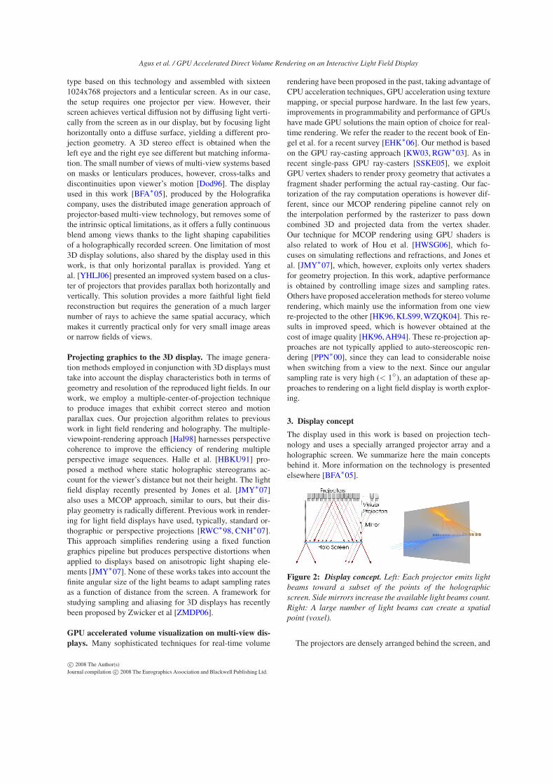
The display used in this work is based on projection tech-nology and uses a specially arranged projector array and aholographic screen. We summarize here the main conceptsbehind it. More information on the technology is presentedelsewhere [BFA∗05].
Figure 2: Display concept. Left: Each projector emits light
beams toward a subset of the points of the holographic
screen. Side mirrors increase the available light beams count.
Right: A large number of light beams can create a spatial
point (voxel).
The projectors are densely arranged behind the screen, and
c© 2008 The Author(s)Journal compilation c© 2008 The Eurographics Association and Blackwell Publishing Ltd.

Agus et al. / GPU Accelerated Direct Volume Rendering on an Interactive Light Field Display
all of them project their specific image onto the holographicscreen to build up a light field (see figure 2). By positioningmirrors at the sides of the display, it is possible to reflect backonto the screen the light beams that would otherwise be lost,thus creating virtual projectors that increase the display fieldof view. Each projector emits light beams toward a subset ofthe points of the holographic screen. At the same time, eachscreen point is hit by more light beams coming from differ-ent projectors. The holographic screen is the key element inthis design, as it is the optical element enabling selective di-rectional transmission of light beams. It is a holographicallyrecorded, randomized surface relief structure able to providecontrolled angular light divergence. The light diffusion char-acteristic of the screen is the critical parameter influencingthe angular resolution of the system, which is very preciselyset in accordance with the system geometry. In the horizon-tal parallax design, the projectors are arranged in a horizontallinear array and the angular light distribution profile inducedby the screen is strongly anisotropic. Horizontally, the surfaceis sharply transmissive, to maintain a sub-degree separationbetween views. Vertically, the screen scatters widely so theprojected image can be viewed from essentially any height.The angular light distribution profile introduced by the holo-graphic screen is characterized by a wide plateau and steepGaussian slopes precisely overlapping in a narrow region inthe horizontal direction. This results in a homogeneous lightdistribution and continuous 3D view with no visible crosstalkwithin the field of depth determined by the angular resolu-tion. A full parallax system would be created using a screenwith narrow transmission profiles both in the horizontal andvertical direction. This design would require, however, a ma-trix of projectors for generating a much larger number ofrays, significantly increasing the computational cost of imagegeneration. Since humans perceive depth using horizontally-offset eyes and move their viewpoint more easily from sideto side than up and down, the horizontal parallax only ap-proach is adequate for most applications and provides signif-icant speed-up.
4. Light field geometry
With proper software control, the light beams leaving the var-ious pixels can be made to propagate in specific directions,as if they were emitted from physical objects at fixed spatiallocations. Reconstructing the light field of a rendered sceneamounts to precomputing the projection parameters associ-ated to each of the projectors and to using them for generatingmultiple views for the same image.
Geometric and photometric calibration data can be ob-tained with many of the existing automated multi-projectorcalibration techniques [BMY05]. In particular, geometric cal-ibration is straightforward using the classic two-step ap-proach in which position and frustum of each projector arefound through parametric optimization of an idealized pin-hole model and any remaining error is corrected using a post-rendering 2D image warp that “moves” the pixels to the cor-
rect idealized position. In our case, the parametric model isparticularly compact, given the simple geometry of the dis-play. We assume that the screen is centered at the origin withthe y axis in the vertical direction, the x axis pointing to theright, and the z axis pointing out of the screen. Each pro-jector is then modeled by a pinhole emitter with origin atE = (Ex,Ey,Ez) and projecting an image on the plane z = 0.The projected image geometry is defined by a 2D rectangleR−,R+ orthogonal to the Z axis. The effect of the lateral mir-rors is captured by creating virtual projectors and recoveringtheir parameters in the calibration procedure as done for thereal ones.
Projecting graphics to the display. This simple linear per-spective model defines how light is projected onto the screen,but is not sufficient to define how a 3D graphics appli-cation should project their models to the display, becauseit ignores the transformation performed by the holographicscreen. Since the screen is selective only in the horizontal di-rection, but scatters widely in the vertical one, the displayedlight field’s dimensionality is reduced, and the applicationmust decide how to deal with the missing degree of freedom.In practice, at any moment in time, a given screen pixel hasthe same color when viewed from all vertical viewing angles.In order to provide a full perspective effect, the vertical view-ing angle must thus be known, which amounts at fixing theviewer’s height and distance from screen.
Therefore, the renderer assumes a virtual viewer at heightVy and distance Vz from the screen. Given a world space pointP, its screen projected position S for a given emitter E canthus be computed for the x coordinate by intersecting the rayoriginating from the emitter E with the screen plane at z = 0and for the y coordinate by intersecting it with the ray arrivingto the virtual viewer V (see figure 3):
Sx = Ex −Ez ·Ex −Px
Ez −Pz
Sy = Vy −Vz ·Vy −Py
Vz −Pz(1)
For rendering, e.g., in a rasterization application, the worldspace position S is remapped to normalized projected coordi-nates by transforming to the image rectangle and associatinga depth (for Z-buffering) based on distance to the screen:
Hx =(Sx −Ex) ·2− (R+
x +R−x )
R+x −R−
x
Hy =(Sy −Ey) ·2− (R+
y +R−y )
R+y −R−
y
Hz = −Pz/Vz (2)
With these few operations, we can determine for any 3Dpoint P where it should be drawn on a given projector toproduce a perspective correct image. The solution is exactfor all viewers at the same distance from screen and height
c© 2008 The Author(s)Journal compilation c© 2008 The Eurographics Association and Blackwell Publishing Ltd.

Agus et al. / GPU Accelerated Direct Volume Rendering on an Interactive Light Field Display
Figure 3: Light field geometry: Left: horizontally, the screen is sharply transmissive and maintains separation between views.
Center: vertically, the screen scatters widely so the projected image can be viewed from essentially any height. Right: the finite
angular size of the light beams determines the voxel dimension as a function of distance from the screen.
as the virtual observer and proves in practice to be a goodapproximation for all other viewing positions in the dis-play workspace. A similar approach is taken by Jones etal. [JMY∗07] for their 360◦ light field display. Their ap-proach also employs a MCOP perspective that combines twodifferent viewpoints P (for horizontal coordinates) and V (forvertical coordinates). In their case, however, the geometry ofthe display is significantly more complex, and computing theprojection requires both a ray/plane and a ray/cylinder inter-section per 3D point.
Depth dependent spatial resolution. The display designhas consequences not only on the projection equation but alsoimposes limits on spatial resolution that depends on depth.Each beam leaving the screen has (approximately) a finiteangular size Φ. This, however, introduces a finite resolutioneffect – that is independent from the screen pixel resolution –in the reconstructed three dimensional scene. In fact, the sizes of the smallest voxel that can be reproduced depends onthe distance of its center from the screen and from the beamangular size Φ, and can be approximated by
s(z) = s0 +2‖z‖ tan(Φ/2) (3)
where s0 is the pixel size on the screen surface (see figure 3right). In other words, the achievable spatial resolution de-creases with the distance from the screen. This is intuitivebecause the illusion of existence of a particular spatial pointis generated by pyramidal beams crossing at a specific 3Dposition (see figure 3 right). This fact dictates how volumesshould be sampled when rendering for the display and alsopractically limits the field-of-depth of the display, i.e., themaximum distance from the screen at which objects are faith-fully reconstructed.
5. GPU-based Volume Ray Casting
We exploit the characteristics of the display to develop a spe-cialized volume rendering technique able to provide multiplefreely moving naked-eye viewers the illusion of presence ofvirtual volumetric objects floating at fixed physical locationsin the display workspace. Our light-field display aware vol-ume rendering process follows the two-pass approach typicalof contemporary multi-projector displays [BMY05] (see fig-ure 4). In the first rendering pass, a per projector view of the
Figure 4: Light field display aware volume rendering pro-
cess: In a first 3D rendering pass a volume ray-caster exe-
cuted entirely on the GPU generates a view per projector us-
ing a small linear model for projector alignment. Non-linear
view distortions and color correction is applied in a second
warping pass.
scene is rendered off-screen to a frame buffer object usingthe idealized light field geometry model. In the second pass,performed purely in 2D image space, small non-linear viewand color distortions are corrected by streaming the first passtexture through a fragment shader that warps the geometryand modifies colors thanks to per-pixel lookup tables storedas precomputed textures.
Our 3D rendering framework is based on GPU ray-casting,which has recently emerged as a flexible and efficient frame-work for real-time volume rendering. In this approach, perprojector images of a volume are rendered by casting raysthrough each pixel, and performing resampling and com-positing of successive sample contributions along these rays.The entire volume is stored in a single 3D texture, and re-sampling is performed by fetching samples from this texturewith trilinear texture filtering. For each pixel, a fragment pro-gram steps from sample location to sample location in a loopand performs compositing until the volume is exited or fullopacity is reached. By applying an appropriate optical modelmany desired kinds of interaction between light and the vol-umetric object can be realized.
Fragment generation. The GPU ray-caster is activated byrendering a proxy geometry whose projection on the imageplane covers all pixels emitting rays passing through the vol-ume. The classic approach is to render the volume’s bound-ing box, with per vertex attributes storing the corresponding
c© 2008 The Author(s)Journal compilation c© 2008 The Eurographics Association and Blackwell Publishing Ltd.

Agus et al. / GPU Accelerated Direct Volume Rendering on an Interactive Light Field Display
ray entry and exit points in the volume. Since our display re-quires a MCOP perspective, we cannot rely on the standardfixed-function pipeline to perform this step, since the MCOPcannot be recast into the traditional homogeneous matrix. Inaddition, long straight lines appear curved in the projection,and linear interpolation of vertex attributes does not producecorrect per-pixel ray parameter values. Thus, we use as proxya coarsely tessellated version (8x8 quads) of a slightly en-larged bounding volume and stream its vertices through avertex shader that performs our MCOP projection using equa-tions 1 and 2 and passes down to the fragment stage the nor-malized and unnormalized projected coordinates.
Ray computation and compositing. In order to be able tostep along rays, the ray entry position, direction, and lengthmust be computed for each fragment. Our shader receivesfrom the vertex stage an unnormalized projected positionS computed from equation 1, which represents the screenpixel’s position expressed in the display reference frame. Thedirection d of the ray passing through that point can then becomputed using the MCOP projection parameterized by emit-ter E and virtual viewer parameters V (see figure 3):
d = [Sx −Ex
Ez,
Sy −Vy
Vz,−1] (4)
The infinite ray defined by S,d is then transformed in localvolume coordinates, assumed to be coincident with texturecoordinates, by applying a world-to-texture homogeneoustransform matrix stored in the OpenGL model-view register.Once the ray is transformed in the local texture coordinates,the ray entry point and integration lengths are computed byclipping the line S,d against the unit box. If the length is null,the fragment is considered invalid and discarded, otherwisethe renderer steps through the ray in a loop and performs vol-ume resampling and compositing until the volume is exitedor full opacity is reached. Since spatial resolution is depthdependent, special care must be taken in this step to matchresampling and integration kernels with actual representablevoxel size (see section 4).
In our approach, we store the volume texture in a Mipmappyramid and access it by controlling directly the Mipmap ac-cess through the tex3Dlod intrinsic. At each sampling step,we compute the depth of the current sample by transformingits position in texture space to world (screen aligned) space.Since we are interested only in the single z coordinate thistransformation can be performed using a single dot product.The most appropriate mipmap level l is then chosen by con-sidering the spatial resolution at depth z from the screen find-ing the coarsest level with a sufficiently small voxel size. Thiscan be done by the following equation:
l = median(0,Lmax,⌊log2s(z)
v0⌋) (5)
where s(z) is computed according to equation 3, Lmax is themaximum available Mipmap level and v0 is the voxel size atthe finest Mipmap level. Adaptive stepping is also possible
by using s(z) as variable step-size. Additional optimizations,in particular empty space skipping, can be implemented ontop of this basic approach. Such optimizations are orthogonalto this work and not considered in this paper.
In appendix A, we provide the Cg fragment programsource code containing main ray-caster steps. The code as-sumes that helper functions are defined for basic geometricoperations and leaves undefined the actual compositing tech-nique.
6. Implementation and results
We have implemented a prototype hardware and softwaresystem based on the design discussed in this paper. The soft-ware system proposed in this paper consists of a frameworkwritten in C++ and OpenGL, a set of Cg shaders that imple-ment the basic ray-casting engine, and a number of shaderfunctions that implement different compositing techniques.The display hardware is manufactured by Holografika andis capable of visualizing 7.4M beams/frame by composingoptical module images generated by 96 fast 320x240 LCDdisplays fed by FPGA input processing units that decode aninput DVI stream. The on screen 2D pixel size of the displayis s0 = 1.25mm, and the angular accuracy is 0.8◦.
The DVI channel feeding the display works at 1280x1024at 75Hz. Each 1280x1024 frame collects 16 320x240 pro-jector images, plus a color-encoded header in the top rowsthat encodes the ids of the projectors that have to be up-dated. A full 3D frame is created by sequentially generatingall the projector images into the frame buffer. In this work,the graphics application runs on an Athlon64 3300+ PC witha NVIDIA8800GTX graphics board working in twin-viewmode. One DVI output is used for control on a 2D monitor,while the second one feeds the 3D display.
Interactive sequences. It is obviously impossible to fullyconvey the impression provided by our holographic environ-ment on paper or video. As a simple illustration of our sys-tem’s current status and capabilities, an accompanying videoshows interactive sequences recorded live using a movingcamera. Representative video frames are shown in figure 5.The sequences were recorded with a hand held video camerafreely moving in the display workspace. In order to assess thedistortion caused by the MCOP approach, the video includessequences presenting both vertical and horizontal motions,with the camera moving far from the virtual viewer position.We recorded short inspections and free-hand manipulationof different public domain datasets at the resolution of 2563
voxels at 8bit/sample: The Visible Human Male head †, theChameleon CT scan ‡, and a contrasted rotational angiogra-
† Source: The National Library of Medicine, USA‡ Source: Digital Morphology Project, the CTLab and the Texas Ad-vanced Computing Center, University of Texas, Austin
c© 2008 The Author(s)Journal compilation c© 2008 The Eurographics Association and Blackwell Publishing Ltd.

Agus et al. / GPU Accelerated Direct Volume Rendering on an Interactive Light Field Display
Figure 5: Frames from live recordings. These images, taken from the accompanying video, show successive instants of inter-
active exploration of different CT datasets.
phy of a human head with aneurysm §. Currently, our proto-type volume ray caster implements a number of compositionstrategies, that include Maximum Intensity Projection (MIP),Simulated X-Ray, as well as Direct Volume Rendering with aPhong illumination model, boundary enhancement and view-dependent transparency [BG07]. For rendering, the volume isstored in a single 4 component texture that contains the un-scaled precomputed gradient in the RGB part and the voxelvalue in the A part. An additional one-dimensional RGBAtexture contains an interactively modifiable look-up table. Inthe accompanying video, the Chameleon and Visible Humanhead datasets are rendered using a shaded volume rendering,while the rotational angiography dataset employs a maximumintensity projection.
As demonstrated in the video, objects appear to movingviewers floating in the display space and can be manipu-lated by translating, rotating, and scaling them with a six de-gree of freedom tracker, as well as by modifying the transferfunction. Note the parallax effects and the good registrationbetween displayed object space and physical space, whichdemonstrate the multi-user capability of the display and the
§ Source: Volume Dataset Repository at the WSI/GRIS, Universityof Tübingen, Germany
good performance of the MCOP viewing approach. Pleasealso note that specular highlights correctly follow the record-ing camera’s viewpoint, contributing to volume readability.As illustrated by the video, the perceived image is fully con-tinuous. This is qualitatively very different from other con-temporary multiview technologies, which force users intoapproximately fixed positions, because of the abrupt view-image changes that appear when crossing discrete viewingzones [MP04].
The main limiting factor during interaction was given bythe single GPU volume renderer performance, since at fullresolution (1 ray/pixel and 1 sample/voxel), many millions ofrays need to be propagated for hundreds of steps through thevolume. In order to improve interactive frame rates, we havethus chosen the solution of lowering the sampling rate dur-ing interaction, by reducing the pixel count (2.5mm precisionon screen) and doubling the integration step-size. Since thedisplay projectors are sequentially updated in batches of 16320x240 images, a misalignment between tiles can becomevisible when objects are moved with a too slow refresh rate(see figure 6). It is important to note that even when a sin-gle “static” 3D view is displayed, users can exploit accom-modation, stereo and motion parallax to gain understandingof complex shapes. Some of these cues can be also obtainedwith traditional systems, but only by incorporating interactive
c© 2008 The Author(s)Journal compilation c© 2008 The Eurographics Association and Blackwell Publishing Ltd.

Agus et al. / GPU Accelerated Direct Volume Rendering on an Interactive Light Field Display
manipulation in the rendering system. In that case, users willhave to move the object or the viewpoint to provide the visualsystem with enough depth information. The task is not simpleand immediate, and depth information is easily lost when theuser stops interacting.
Figure 6: Dynamic tile misalignment effect. The 96 dis-
play projectors are updated in batches of 16 projectors each,
which can lead to artifacts in dynamic motion if the render-
ing rate is too slow (left). These artifacts disappear when the
image is static (right).
Enhanced 3D understanding. To quickly evaluate whetherthe light field rendering infrastructure is able to help inrapidly gaining understanding of complex 3D shapes we per-formed two simple experiments.
Figure 7: Random dot masking test. Left: Stimulus. Right:
central view as presented by the display.
In a first synthetic benchmark using random-dot masking,we employed a simplified version of Julesz’s spiral ramp sur-face: a 3-layer cylindrical wedding-cake model that subjectsviewed along its concentric axis (see figure 7). By adjust-ing the model’s parameters and converting it to a rectilinearvolume, two sets of model-stimuli were rendered using ourframework: one with a uniform large field of depth (±10cm
centered on the display screen) and one where the field wasalmost flat (±1cm). Each of eleven, pre-screened, subjectscompleted four experiments, each consisting of eight trials ina two-interval forced-choice (2IFC) design whereby they in-dicated in which interval they perceived the greatest field ofdepth. The experiments tested one-eye static, one-eye head-swaying, two-eye static, and two-eye head-swaying observa-tion in that order. Scores improved also in that order: from49%, i.e., indistinguishable from a random answer in the bi-nary test, with a monocular static view, to 82% correct scoresfor the monocular head-swaying test, up to 100% when allcues are available. The results indicate that in the absence ofcues mundanely available to 2D displays the light field ren-dering system elicits useful stereoscopic and motion-parallaxdepth cues.
Figure 8: MIP volume rendering of rotational angiography
scan of a head with aneurysm. Left: Since the technique is
depth-oblivious, the position and crossing of vascular struc-
tures is not detectable. Right: the light field display provides
rapid volumetric understanding.
In a second, less formalized, test, we consider a rotationalangiography scan of a head with aneurysm rendered using thecommonly employed MIP modality. MIP is a simple volumerendering composing approach where the maximum valueencountered along a ray is used to determine the color of thecorresponding pixel. It is considered very useful for visual-izing angiography data sets, since the data values of vascu-lar structures with contrast agent are higher than the valuesof the surrounding tissues and are therefore not masked byother data. From a single MIP image, however, recovering3D structures is impossible, since the technique does not pro-vide adequate depth cues (see figure 8). That’s why currentbest medical practices suggest to always correlate MIP im-ages with direct volume-rendered images, in order to demon-strate 3D relationships [FNH∗06]. This dual representationapproach, however, adds complexity to the image analysistasks, since MIP images, besides being more familiar to themedical community, require also substantially less parametertuning and produce results which are more reproducible bydifferent operators/systems. When looking at the test angiog-raphy dataset on our light field display, we verified that usersare able to very rapidly recover all depth cues and to instanta-neously recognize the vascular structure because of the com-bination of stereo and motion parallax. Previous work hasverified the importance of stereopsis for this task [ME04], aswell as the importance of dynamic cues [BBD∗07]. Our sys-tem seamlessly combines both cues, and, in addition achievesparallax effects through ego-motion rather than interaction.
7. Conclusions and Future Work
The prototype discussed here is clearly meant to work as anenabling technology demonstrator, as well as a testbed for in-tegrated volumetric rendering and light field display research.A first conclusion than can be drawn from our work is thathigh quality volumetric rendering on light field displays iscurrently achievable even when using single GPU desktopsolution for the rendering task. In order to deal with largescale datasets, we are already working on a out-of-core par-allel multi-GPU renderer. We are also investigating how toimprove rendering speed by incorporating optimization thatexploit the high degree of coherence present in a 3D view.There is obviously more to interactive volumetric rendering
c© 2008 The Author(s)Journal compilation c© 2008 The Eurographics Association and Blackwell Publishing Ltd.

Agus et al. / GPU Accelerated Direct Volume Rendering on an Interactive Light Field Display
on 3D displays than employing standard composition tech-niques. Devising which of the recently proposed expressivevisualization techniques are appropriate for 3D displays isbeyond the scope of this paper, which focuses on enablingrendering technology. Exploring this domain through the de-sign and implementation of highly interactive techniques thatleverage the unique features of an interactive multi-viewer3D environment is a challenging area for future work. Fu-ture work will also focus on perceptual evaluation of the 3Ddisplay with respect to depth discrimination tasks. In thiscontext, we also plan to evaluate the effects induced by ourmultiple-center-of-projection approximation.
Acknowledgments. This work is partially supported by the ItalianMinistry of Research under the CYBERSAR project and by the EUMarie Curie Program under the 3DANATOMICALHUMAN project(MRTN-CT-2006-035763).
References
[AH94] ADELSON S., HANSEN C.: Fast stereoscopic im-ages with Ray-Traced volume rendering. In Symposium on
Volume Visualization (1994), pp. 3–10.
[BBD∗07] BOUCHENY C., BONNEAU G.-P., DROULEZ
J., THIBAULT G., PLOIX S.: A perceptive evaluationof volume rendering techniques. In Proc. ACM APGV
(2007), pp. 83–90.
[BFA∗05] BALOGH T., FORGÁCS T., AGOCS T., BALET
O., BOUVIER E., BETTIO F., GOBBETTI E., ZANETTI
G.: A scalable hardware and software system for the holo-graphic display of interactive graphics applications. InEurographics Short Papers Proceedings (2005), pp. 109–112.
[BG07] BRUCKNER S., GRÖLLER M. E.: Style trans-fer functions for illustrative volume rendering. Computer
Graphics Forum 26, 3 (Sept. 2007), 715–724.
[BMY05] BROWN M., MAJUMDER A., YANG R.:Camera-based calibration techniques for seamless multi-projector displays. IEEE Trans. Vis. Comput. Graph 11, 2(2005), 193–206.
[CNH∗07] COSSAIRT O., NAPOLI J., HILL S., DORVAL
R., FAVALORA G.: Occlusion-capable multiview volumet-ric three-dimensional display. Applied Optics 46, 8 (Mar.2007), 1244–1250.
[DML∗00] DODGSON N. A., MOORE J. R., LANG S. R.,MARTIN G., CANEPA P.: Time-sequential multi-projectorautostereoscopic 3D display. J. Soc. for Information Dis-
play 8, 2 (2000), 169–176.
[Dod96] DODGSON N. A.: Analysis of the viewing zone ofthe Cambridge autostereoscopic display. Applied Optics:
Optical Technology & Biomedical Optics 35, 10 (1996),1705–1710.
[Dod05] DODGSON N. A.: Autostereoscopic 3D Display.Computer 38, 8 (2005), 31–36.
[EHK∗06] ENGEL K., HADWIGER M., KNISS J., REZK-SALAMA C., WEISKOPF D.: Real-time Volume Graphics.AK-Peters, 2006.
[FDHN01] FAVALORA G., DORVAL R., HALL D.,NAPOLI J.: Volumetric three-dimensional display sys-tem with rasterization hardware. In Proc. SPIE (2001),vol. 4297, pp. 227–235.
[FNH∗06] FISHMAN E. K., NEY D. R., HEATH D. G.,CORL F. M., HORTON K. M., JOHNSON P. D.: Volumerendering versus maximum intensity projection in CT An-giography: What works best, when, and why. RadioGraph-
ics 2006 26, 3 (May–June 2006), 905–922.
[GTH05] GHOSH A., TRENTACOSTE M., HEIDRICH W.:Volume rendering for high dynamic range displays. InEurographics/IEEE VGTC Workshop on Volume Graphics
(2005), pp. 91–98.
[Hal98] HALLE M.: Multiple viewpoint rendering. InProc. SIGGRAPH (1998), pp. 243–254.
[HBKU91] HALLE M. W., BENTON S. A., KLUG M. A.,UNDERKOFFLER J. S.: Ultragram: a generalized holo-graphic stereogram. In Proc. SPIE (July 1991), vol. 1461,pp. 142–155.
[HK96] HE T., KAUFMAN A.: Fast stereo volume render-ing. In Proc. Visualization (1996), pp. 49–ff.
[HMG03] HUEBSCHMAN M., MUNJULURI B., GARNER
H.: Dynamic holographic 3-d image projection. Optics
Express 11 (2003), 437–445.
[HWSG06] HOU X., WEI L.-Y., SHUM H.-Y., GUO B.:Real-time multi-perspective rendering on graphics hard-ware. In Proc. 17th Eurographics Workshop on Rendering
(2006), pp. 93–102.
[JMY∗07] JONES A., MCDOWALL I., YAMADA H., BO-LAS M. T., DEBEVEC P. E.: Rendering for an interactive360 degree light field display. ACM Trans. Graph 26, 3(2007), 40.
[KLS99] KOO Y.-M., LEE C.-H., SHIN Y.-G.: Object-order template-based approach for stereoscopic volumerendering. Journal of Visualization and Computer Anima-
tion 10, 3 (1999), 133–142.
[KW03] KRUEGER J., WESTERMANN R.: Accelerationtechniques for GPU-based volume rendering. In Proc. Vi-
sualization (2003), pp. 287–292.
[ME04] MORA B., EBERT D. S.: Instant volumetricunderstanding with order-independent volume rendering.Computer Graphics Forum 23, 3 (2004), 489–497.
[MMMR00] MCKAY S., MAIR G., MASON S., REVIE
K.: Membrane-mirror based autostereoscopic display forteleoperation and telepresence applications. In Proc. SPIE
(2000), vol. 3957, pp. 198–207.
[MP04] MATUSIK W., PFISTER H.: 3D TV: a scalable sys-tem for real-time acquisition, transmission, and autostereo-
c© 2008 The Author(s)Journal compilation c© 2008 The Eurographics Association and Blackwell Publishing Ltd.
Agus et al. / GPU Accelerated Direct Volume Rendering on an Interactive Light Field Display
scopic display of dynamic scenes. ACM Transactions on
Graphics 23, 3 (Aug. 2004), 814–824.
[PPN∗00] PORTONI L., PATAK A., NOIRARD P., GROS-SETIE J.-C., VAN BERKEL C.: Real-time auto-stereoscopic visualization of 3D medical images. In Proc.
SPIE (Apr. 2000), Mun S. K., (Ed.), vol. 3976, pp. 37–44.
[RGW∗03] ROETTGER S., GUTHE S., WEISKOPF D.,ERTL T., STRASSER W.: Smart hardware-accelerated vol-ume rendering. In Proc. VISSYM (2003), pp. 231–238.
[RR05] RELKE I., RIEMANN B.: Three-dimensional mul-tiview large projection system. In Proc. SPIE (2005),vol. 5664.
[RS00] ROBERTS J. W., SLATTERY O.: Display character-istics and the impact on usability for stereo. In Proc. SPIE
(2000), vol. 3957, p. 128.
[RWC∗98] RASKAR R., WELCH G., CUTTS M., LAKE
A., STESIN L., FUCHS H.: The office of the future: Aunified approach to image-based modeling and spatiallyimmersive displays. In Proc. SIGGRAPH (1998), pp. 179–188.
[SCC∗00] STANLEY M., CONWAY P., COOMBER S.,JONES J., SCATTERGOOD D., SLINGER C., BANNISTER
B., BROWN C., CROSSLAND W., TRAVIS A.: A novelelectro-optic modulator system for the production of dy-namic images from giga-pixel computer generated holo-grams. In Proc. SPIE (2000), vol. 3956, pp. 13–22.
[SHLS∗95] ST.-HILLAIRE P., LUCENTE M., SUTTER J.,PAPPU R., SPARRELL C. G., BENTON S.: Scaling up themit holographic video system. In Proc. 5th SPIE Sympo-
sium on Display Holography (1995), pp. 374–380.
[SSKE05] STEGMAIER S., STRENGERT M., KLEIN T.,ERTL T.: A simple and flexible volume rendering frame-work for graphics-hardware-based raycasting. In Eu-
rographics/IEEE VGTC Workshop on Volume Graphics
(2005), pp. 187–195.
[vPF96] VAN BERKEL C., PARKER D., FRANKLIN A.:Multiview 3d-lcd. In Proc. SPIE (1996), vol. 2653, p. 32.
[WHJ∗00] WOODGATE G. J., HARROLD J., JACOBS A.M. S., MOSELEY R. R., EZRA D.: Flat-panel autostereo-scopic displays: characterisation and enhancement. InProc. SPIE (2000), vol. 3957, p. 153.
[WZQK04] WAN M., ZHANG N., QU H., KAUFMAN
A. E.: Interactive stereoscopic rendering of volumetric en-vironments. IEEE Transactions on Visualization and Com-
puter Graphics 10, 1 (2004), 15–28.
[YHLJ06] YANG R., HUANG X., LI S., JAYNES C.: To-ward the light field display: Autostereoscopic renderingvia a cluster of projectors. In Eurographics Short Papers
Proceedings (2006).
[ZMDP06] ZWICKER M., MATUSIK W., DURAND F.,PFISTER H.: Antialiasing for automultiscopic 3D displays.
In Proc. Eurographics Symposium on Rendering (2006),pp. 73–82.
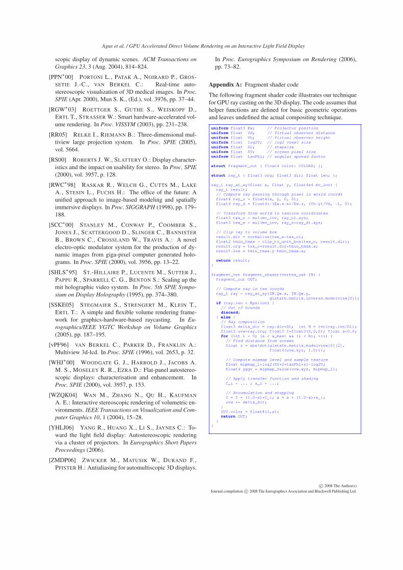
Appendix A: Fragment shader code
The following fragment shader code illustrates our techniquefor GPU ray casting on the 3D display. The code assumes thathelper functions are defined for basic geometric operationsand leaves undefined the actual compositing technique.
uniform float3 Ew; // Projector position
uniform float Vd; // Virtual observer distance
uniform float Vh; // Virtual observer height
uniform float log2V; // log2 voxel size
uniform float DL; // stepsize
uniform float S0; // screen pixel size
uniform float tanPhi; // angular spread factor
struct fragment_out { float4 color: COLOR0; };
struct ray_t { float3 org; float3 dir; float len; };
ray_t ray_at_xy(float x, float y, float4x4 mv_inv) {
ray_t result;
// Compute ray passing through pixel in world coords
float4 ray_o = float4(x, y, 0, 0);
float4 ray_d = float4(-(Ew.x-x)/Ew.z, (Vh-y)/Vd, -1, 0);
// Transform from world to texture coordinates
float3 tex_o = mul(mv_inv, ray_o).xyz;
float3 tex_e = mul(mv_inv, ray_o+ray_d).xyz;
// Clip ray to volume box
result.dir = normalize(tex_e-tex_o);
float2 tmin_tmax = clip_to_unit_box(tex_o, result.dir);
result.org = tex_o+result.dir*tmin_tmax.x;
result.len = tmin_tmax.y-tmin_tmax.x;
return result;
}
fragment_out fragment_shader(vertex_out IN) {
fragment_out OUT;
// Compute ray in tex coords
ray_t ray = ray_at_xy(IN.Qw.x, IN.Qw.y,
glstate.matrix.inverse.modelview[0]);
if (ray.len < Epsilon) {
// Out of bounds
discard;
} else {
// Ray composition
float3 delta_dir = ray.dir*DL; int N = int(ray.len/DL);
float3 uvw=ray.org; float3 I=float3(0,0,0); float a=0.0;
for (int i = 0; (a < a_max) && (i < N); ++i) {
// Find distance from screen
float z = abs(dot(glstate.matrix.modelview[0][2],
float4(uvw.xyz, 1.0)));
// Compute mipmap level and sample texture
float mipmap_l=log2(S0+2*tanPhi*z)-log2V;
float4 gggv = mipmap_value(uvw.xyz, mipmap_l);
// Apply transfer function and shading
C_i = ... ; a_i = ...;
// Accumulation and stepping
I = I + (1.0-a)*C_i; a = a + (1.0-a)*a_i;
uvw += delta_dir;
}
OUT.color = float4(I,a);
return OUT;
}
}
c© 2008 The Author(s)Journal compilation c© 2008 The Eurographics Association and Blackwell Publishing Ltd.