grade 11 november 2018
TRANSCRIPT

NATIONAL
SENIOR CERTIFICATE
GRADE 11
NOVEMBER 2018
MECHANICAL TECHNOLOGY: FITTING AND TURNING MARKING GUIDELINE
MARKS: 200
This marking guideline consists of 12 pages.

2 MECHANICAL TECHNOLOGY (FITTING AND TURNING) (EC/NOVEMBER 2018)
Copyright reserved Please turn over
SECTION A: COMPULSORY
QUESTION 1: MULTIPLE-CHOICE QUESTIONS
1.1 B 1.2 C 1.3 D 1.4 D 1.5 B 1.6 A 1.7 C 1.8 C 1.9 D 1.10 A 1.11 C 1.12 B 1.13 A 1.14 D 1.15 C 1.16 B 1.17 A 1.18 D 1.19 C 1.20 C (20 x 1) [20]
QUESTION 2: SAFETY
2.1 Arc Welding Equipment
Wear approved personal protective equipment (PPE).
Wear PPE that is fire-resistant to protect the welder against sparks, etc.
Use completely insulated electrode holders.
At no time strike an arc without protecting your eyes with a helmet or welding shield.
Always wear safety goggles to protect your eyes from particles of metal and chips of slag.
Stand and work only in dry surroundings.
Always keep your hands and clothing dry. (Any 3 x 1) (3)
2.2 General machine safety
The working area around all machines must be clearly indicated.
All moving parts must be covered by rigidly constructed guards.
If access to a machine is necessary, the guard must be able to hinge or slide open while the machine automatically switches off.
No machine may be operated if any of the guards are missing or broken. (Any 3 x 1) (3)
2.3 Bending press (Box and Pan)
Before use, check if the machine is mounted securely, especially the bench-mounted type.
Make sure not to exceed the indicated load limit (thickness of the sheet metal) of the machine.
Use this machine only to bend sheet metal, not rods or angle iron.
Do not use any extensions on the folding bar levers. (Any 3 x 1) (3)

(EC/NOVEMBER 2018) MECHANICAL TECHNOLOGY (FITTING AND TURNING) 3
Copyright reserved Please turn over
2.4 Reporting to persons in charge (C3)
The worker must report:
Maintenance requirements of machines or equipment so that the flow of production is not interrupted.
Progress on work in operation.
Problems encountered in the manufacturing process.
Material and equipment requirements.
Accidents must be reported immediately. (Any 1 x 1) (1)
2.5 Angle grinder:
The safety guard must be in place before you can start the grinding process.
Protective shields must be placed around the object being ground to protect passers-by.
Use the correct grinding disc for the job.
Do not use excessive force while grinding and cutting.
Make certain that there are no cracks on the disc before you start a job.
Protective clothing and eye protection are essential when working with an angle grinder.
Beware of lockable switches in the ‘on’ position when machine is plugged in and switched on. (Any 3 x 1) (3)
2.6 Drill press safety:
Clamp the workpiece securely to the table and do not hold it by hand. (1)
2.7 Surface grinder:
Protective clothing and eye protection are essential when operating a surface grinder.
Understand the operating instructions applicable to your machine.
Do not operate the surface grinder unless all guards and safety devices are in place and working correctly.
Never clean or adjust the machine while it is in motion.
Immediately report any dangerous defects of the machine and stop using it until it has been repaired by a qualified person.
Do not use excessive force when drilling into the workpiece. (Any 3 x 1) (3) 2.8 PPE Gas welding:
Overall
Leather gloves
Welding goggles
Welding spats
Safety boots (Any 3 x 1) (3)

4 MECHANICAL TECHNOLOGY (FITTING AND TURNING) (EC/NOVEMBER 2018)
Copyright reserved Please turn over
2.9 Unsafe conditions in the workshop:
Insufficient lighting in the working area to the extent that the worker cannot clearly see what he or she is doing.
Insufficient ventilation, especially where welding, grinding, testing of petrol or diesel engines, or work involving chemicals is being carried out.
Working in an area where construction is taking place.
Working in an area where the floor is unsafe due to its being unstable, cracked, full of holes, weakened by rotten floorboards or wet due to liquid spills, especially oily ones.
Badly planned workshop layout.
Workshop that is crowded, with piles of materials and / or equipment in passageways and working areas.
Blocked or not clearly marked emergency exits.
A lack of suitable machine emergency exits.
A lack of suitable machine guards and guard rails. (Any 2 x 1) (2) 2.10 Categories of OHS:
Conditions
Actions (2) [24] QUESTION 3: TOOLS AND EQUIPMENT
3.1 3.1.1 Pedestal bench grinder (1)
3.1.2 A – Head / Motor B – Disc guard C – Maximum gap (3 mm) D – Grinding wheel E – Perspex shield F – Tool rest (6)
3.1.3 Perspex shield is to protect your eyes from the grinding debris. (1)
3.2 Manual guillotine:
A manual guillotine is designed to cut sheet metal that is not thicker than 1,2 mm. It is usually able to accommodate sheets not wider than 1,2 mm. (2)
3.3 Press machine:
Manual and hydraulic (2)
3.4 3.4.1 Function – horizontal band saw:
It is to cut large metal sections in a horizontal position. (2)
3.4.2 Function – Power saw:
It is used to rough cut (2) [16]

(EC/NOVEMBER 2018) MECHANICAL TECHNOLOGY (FITTING AND TURNING) 5
Copyright reserved Please turn over
QUESTION 4: MAINTENANCE (GENERIC) 4.1 Required drill speed:
N = 𝑆
𝜋.25
= 700
78,55
= 8,91 r/s (3) 4.2 Lack of lubrication on the chuck:
The moving parts that require lubrication should be oiled regularly to ensure free motion and prevent rust. (1)
4.3 Overloading:
It occurs when the drill bit is forced into the material at a rate that exceeds the rate at which the drill can cut and expel the cuttings. (2)
4.4 Causes of malfunction – power saw:
Failure due to lack of lubrication. Incorrect lubrication to the oil in gearboxes and moving parts. (2)
[8] QUESTION 5: MATERIALS 5.1 5.1.1 Plasticity:
It allows the material to change shape permanently. It is the reverse of elasticity. (2)
5.1.2 Ductility:
It allows the material to change shape by stretching it along its length without breaking or drawing it into wire form. (2)
5.1.3 Brittleness:
It causes the material to break easily and fractures may occur with little or no deformation. (2)
5.2 Iron age:
The prehistoric era 1500–1000 BC was known as the Iron Age. (1) 5.3 Operational function of blast furnace:
It is charged with alternative layers of iron ore, coke and limestone.
The raw materials are supplied at the top of the furnace, through a hopper.
The hot air from the stoves is blown through the nozzles.
The nozzles are located near the base of the blast furnace.
The carbon in the coke and the oxygen in the air combine to form a toxic carbon monoxide gas at a temperature of about 1 648 °C.
This reduces the iron ore to metallic iron. (6)

6 MECHANICAL TECHNOLOGY (FITTING AND TURNING) (EC/NOVEMBER 2018)
Copyright reserved Please turn over
5.4 5.4.1 Labels: Electric arc furnace A – Charging ladle
B – Funnel C – Scrap metal D – Steel E – Slag thimble F – Charging machine G – Charging boxes (7)
5.4.2 Function – Electric arc furnace:
It is used for the production of stainless steel. (2) 5.5 Cold chisels:
Heat it to a bright red, about 75 mm from the point, then dip the point of the chisel in water. This must be just dipped, and moved up and down slightly to avoid a sharp line of demarcation between the hard and soft, which may, if it occurs, cause the hard end to shear off bodily then the chisel is put to use. As soon as the actual edge is quenched to cold, move the chisel rapidly to the anvil, lay the hard end across the edge to support it, and rub both sides with a stone. This brightens it sufficiently for the operator to see the temper colours as they appear, coming up in straight lines across the shank. (Any 4 x 1) (4)
5.6 Procedure:
Tempering (2)
5.7 Difference between hardening and tempering:
Hardening is when you dunk red-hot metal into cold water, and tempering is when you take that hardened metal, heat it slightly, and then let it cool slowly. (4)
[32]

(EC/NOVEMBER 2018) MECHANICAL TECHNOLOGY (FITTING AND TURNING) 7
Copyright reserved Please turn over
QUESTION 6: TERMINOLOGY (SPECIFIC)
6.1 Key and keyway calculations:
6.1.1 The width of the key = 𝐷𝑖𝑎𝑚𝑒𝑡𝑒𝑟
4
= 120 / 4 = 30 mm (2)
6.1.2 The thickness of the key =𝐷𝑖𝑎𝑚𝑒𝑡𝑒𝑟 𝑜𝑓 𝑠ℎ𝑎𝑓𝑡
6
= 120/6 = 20 mm (2)
6.1.3 The length of the key = 1,5 x Diameter of shaft = 1,5 x 120 = 180 mm (2)
6.2 Compound Slide Taper:
𝐶𝑜𝑚𝑝𝑜𝑢𝑛𝑑 𝑠𝑙𝑖𝑑𝑒 𝐴𝑛𝑔𝑙𝑒 tan𝜃
2=
𝐷−𝑑
2 𝑥 𝑙
Tan 𝜃
2 = 39,6 – 22 / (2 x 50)
Tan 𝜃
2 = 0,176
𝜃
2 = 9,98 (5)
6.3 Depth of the thread:
H = 0,866 x P = 0,866 x 3 = 2,598 mm (2)
6.4 Turning operations:
Step turning
Taper turning
Thread cutting
Boring
Facing
Straight Turning
Parting (Any 5 x 1) (5)
6.5 Taper-turning procedure
The base of the compound slide or top of the cross slide comprises of a circular plate that is marked off in degrees.
Loosen the base screws and set the compound slide to the desired angle.
Tighten the screws to lock it into position.
The tool should be set with its cutting point exactly level with the lathe’s centre line.
The carriage should always be locked to the lathe bed when cutting short tapers.
When the cutting action has started, use the compound slide handle to feed. (Any 3 x 1) (3)
8 MECHANICAL TECHNOLOGY (FITTING AND TURNING) (EC/NOVEMBER 2018)
Copyright reserved Please turn over
6.7 Arbor and shank cutters used on the milling machines:
Arbor cutters Shank cutters
Involute gear cutter End mill
Helical cutter T-slot
Side-and-face cutter Flute mill
(Any 2) (Any 2) (4)
[25] QUESTION 7: TOOLS AND EQUIPMENT (SPECIFIC) 7.1 Functions:
7.1.1 A wrench is used during manual thread cutting to hold different sizes of
dies. (1)
7.1.2 Chuck key is a tool used to loosen and tighten the chuck of a drilling or
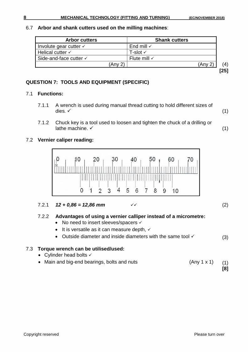
lathe machine. (1) 7.2 Vernier caliper reading:
7.2.1 12 + 0,86 = 12,86 mm (2)
7.2.2 Advantages of using a vernier calliper instead of a micrometre:
No need to insert sleeves/spacers
It is versatile as it can measure depth,
Outside diameter and inside diameters with the same tool (3) 7.3 Torque wrench can be utilised/used:
Cylinder head bolts
Main and big-end bearings, bolts and nuts (Any 1 x 1) (1) [8]

(EC/NOVEMBER 2018) MECHANICAL TECHNOLOGY (FITTING AND TURNING) 9
Copyright reserved Please turn over
QUESTION 8: FORCES (SPECIFIC) 8.1 Basic mechanics calculations: 8.1.1 Symbol for pressure – P (1) 8.1.2 Units for area – m² (1) 8.1.3 Meaning of RPM – Revolutions per minute (1) 8.2 Beam calculations:
Moments at RL (25 x 25) + (50 x 75) = RR x 100
RR = 43,75 kN Moments at RR
(50 x 25)+ (25 x 75) = RL x 100
RL = 31;75 kN (4) 8.3 Stress calculations:
A = 𝜋(𝐷2− 𝑑²)
4
= (0.06²-0.054²) / 4 = 5.372 x 10^-3 m²
𝛿 = 𝐹
𝐴
= 60 x 10^ 3/ 5,372 x 10^-3
= 111’687 679. 4 Pa = 111,688 MPa (5)
8.4 Components of forces:
Xcom = 45 + 30 Cos 45
= 66,213 N
Ycom = 50 – 30 Sin 45
= 28,786 N
𝑅2 = 𝑋² + 𝑌²
R = √66.213² + 28.786²
R = 72,2 N (7) [19]

10 MECHANICAL TECHNOLOGY (FITTING AND TURNING) (EC/NOVEMBER 2018)
Copyright reserved Please turn over
QUESTION 9: MAINTENANCE (SPECIFIC) 9.1 Lubrication terms/abbreviation: 9.1.1 Viscosity is the resistance of oil to flow (2) 9.1.2 Flash point is the temperature at which an oil will give off enough
inflammable vapour flash momentary, when an open flame is brought to its surface (2)
9.1.3 SAE – Society of Automotive Engineers (2) 9.2 Laws of sliding friction: The friction force is in direct relation to the total force between two surfaces.
It is dependent on the size of the surfaces in contact with each other.
It depends on the roughness of the surface and the material the workpiece is made of.
It is dependent on the speed of movement. (Any 2) (2) [8] QUESTION 10: JOINING METHODS (SPECIFIC) 10.1 Screw threads:
(8)
10.2 Lead of the screw thread:
Lead = Number of starts x pitch
= 6 x 3 = 21 mm (3)
10.3 Axis of a screw thread is the centre line running longitudinally through the
thread. (1) [12]
A- Crest
B- Pitch
C- Root
D- Thread angle
E- Root diameter
F- PCD
G- Crest diameter
H- Helix Angle

(EC/NOVEMBER 2018) MECHANICAL TECHNOLOGY (FITTING AND TURNING) 11
Copyright reserved Please turn over
QUESTION 11: SYSTEMS AND CONTROL (SPECIFIC) 11.1 Disadvantages of belt drives:
Not suitable for long distance drives
Belt slippage or breaks occurs when heavier duty is driven (2) 11.2 A hydraulic system calculations: 11.2.1 Fluid pressure
𝐴 =𝐷²
4
A = x (0,04)²/4 = 5,0265 x 10 -³ m²
Pressure =𝐹
𝐴
= 275/5,0265 x 10^-3 = 54,71 kPa (5)
11.2.2 Diameter of piston B to lift a load of 5,56 kN
𝐹𝑎
𝐴𝑎=
𝐹𝑏
𝐴𝑏
Db² = 𝐹𝑏 𝑥 𝐷𝑎²
𝐹𝑎
Db = 179,85 mm
Db = 180 mm (3) 11.3 Belt drive system: 11.3.1 Rotation frequency of the driver pulley in r/min (revolutions per
minute) N1 x D1 = N2 x D2
N2 = 733.33 𝑥 036
0.24
N2 = 1099,95 rpm (3) 11.3.2 Power transmitted
Power = (𝑇1−𝑇2) 𝐷 𝑁
60 OR (T1-T2)v
= (T1 –T2)( x 0,36 x 733,33) /60 = 3732,195 Watts (2)
11.3.3 Belt speed of the system in m.s-1 (metres per second):
V = 𝜋𝐷 𝑥𝑁
60
= ( x 0,36 x 733,33) /60
= 13,8229 m/s (1) [16]

12 MECHANICAL TECHNOLOGY (FITTING AND TURNING) (EC/NOVEMBER 2018)
Copyright reserved Please turn over
QUESTION 12: PUMPS (SPECIFIC) 12.1 Advantages of a centrifugal pump:
They are compact, which means they use less floor space.
They are adaptable to different fluids.
The initial installation costs are relatively low.
They have no moving valves and sensitive parts. (Any 2 x 1) (2) 12.2 Differences between a piston pump and plunger pump:
Although the plunger and piston perform the same work, they differ in two ways. The length of a plunger exceeds its stroke length.
The length of piston is shorter than its stroke. (2) 12.3 Pump 12.3.1 Gear pump (1) 12.3.2 1 – Inlet
2 – Outlet 3 – Gears (3)
12.3.3 Operation of the pump:
When the shaft drives gear, it drives the driven gear. Small pockets of oil are trapped between the gear teeth and pump housing.
The rotating spaces between the carry the oil towards the outlet port.
At the time a vacuum is created over the inlet port and oil is drawn from the reservoir. Oil cannot return between the gear teeth and pressure is built up, forcing the oil out through the outlet port. (4)
[12] TOTAL: 200