gradients - dccconcepts home page … · · 2017-07-17in british circles they are comparatively...
TRANSCRIPT
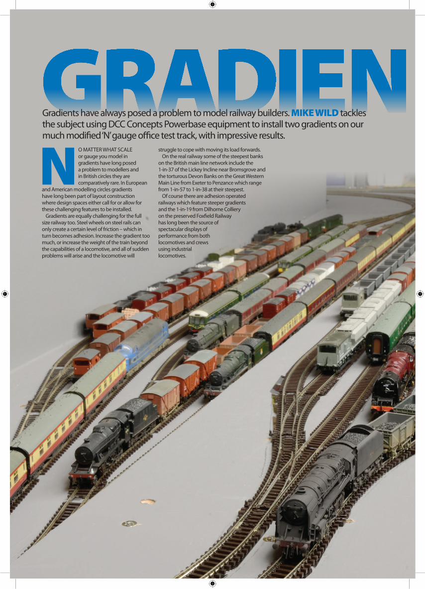
NO MATTER WHAT SCALE or gauge you model in gradients have long posed a problem to modellers and in British circles they are comparatively rare. In European
and American modelling circles gradients have long been part of layout construction where design spaces either call for or allow for these challenging features to be installed.
Gradients are equally challenging for the full size railway too. Steel wheels on steel rails can only create a certain level of friction – which in turn becomes adhesion. Increase the gradient too much, or increase the weight of the train beyond the capabilities of a locomotive, and all of sudden problems will arise and the locomotive will
Gradients have always posed a problem to model railway builders. MIKE WILD tackles the subject using DCC Concepts Powerbase equipment to install two gradients on our much modified ‘N’ gauge office test track, with impressive results.
GRADIENTSstruggle to cope with moving its load forwards.
On the real railway some of the steepest banks on the British main line network include the 1-in-37 of the Lickey Incline near Bromsgrove and the torturous Devon Banks on the Great Western Main Line from Exeter to Penzance which range from 1-in-57 to 1-in-38 at their steepest.
Of course there are adhesion operated railways which feature steeper gradients and the 1-in-19 from Dilhorne Colliery on the preserved Foxfield Railway has long been the source of spectacular displays of performance from both locomotives and crews using industrial locomotives.
GRADIENTS Powerbase tests BR MK 1 CARRIAGES
No Powerbase No Powerbase With Powerbase With Powerbase
Locomotive 1-in-30 1-in-68 1-in-30 1-in-68
Stanier ‘Duchess’ 4-6-2 4 8 8 8
Stanier ‘Jubilee’ 4-6-0 8 8 n/a n/a
Stanier ‘Royal Scot’ 4-6-0 8 8 n/a n/a
BR ‘5MT’ 4-6-0 2 5 7 8
Fairburn 2-6-4T 6 8 8 8
BR ‘9F’ 2-10-0 8 8 n/a n/a
Ivatt ‘2MT’ 2-6-0 3 8 5 8
Fowler ‘Jinty’ 0-6-0T 4 8 6 8
BR 16TON MINERAL WAGONSNo Powerbase No Powerbase With Powerbase With Powerbase
Locomotive 1-in-30 1-in-68 1-in-30 1-in-68
Fowler ‘4F’ 0-6-0 7 24 15 24
BR ‘WD’ 2-8-0 10 10 15 24
BR ‘9F’ 2-10-0 24 24 n/a n/a
Thompson ‘B1’ 4-6-0 24 24 n/a n/a
Stanier ‘Black Five’ 4-6-0 24 24 n/a n/a
Stanier ‘8F’ 2-8-0 24 24 n/a n/a
Ivatt ‘2MT’ 2-6-0 10 24 16 24
Fowler ‘Jinty’ 0-6-0T 15 24 18 24
WEIGHT REDUCTIONWhen it comes to model railways, a level layout has always been seen as the best way forward. However, there are many layout designs where gradients could be employed for a more attractive scenic section or to allow flyovers and the like to be created. Just as with the real railway we need to consider the impact of any gradient and keep as close to level as possible, but there are methods which make the introduction of gradients more attainable.
Our models now are generally lighter than their earlier counterparts. The advancement in detail as manufacture shifted from heavy die-cast bodies to lightweight, highly detailed plastic mouldings means modern locomotives – and particularly in ‘OO’ and ‘N’ gauge – have less adhesive weight than older models. Steam locomotives are particularly prone to being lightweight due to the finesse employed in their creation while diesel locomotives are less affected by this due to the inclusion of heavy die-cast chassis blocks inside.
Traction tyres have made a return on models within the last decade – particularly on steam locomotives – to increase their haulage capacity, but there is another option in DCC Concepts’ Powerbase system which the manufacturer claims can double the haulage capacity of model locomotives! We wanted to test the theory, and test it well, so rather than going for the ‘OO’ gauge version we opted to install Powerbase on our ‘N’ gauge test track to really test its potential.
POWERBASE ELEMENTSDCC Concepts’ Powerbase system consists of two elements - thin steel plates which are specifically designed to sit beneath ‘N’ gauge or ‘OO’ gauge track and specially created high strength NEO
magnets which are fixed underneath locomotives.The magnetic force created by the NEO
magnets enhances adhesion of the locomotive making its bond with the rails stronger and more effective and DCC Concepts also says its Powerbase products also assist with improved electrical pick up and track cleanliness.
The products are supplied in various kits and packs. Powerbase plates can be bought in bulk packs while magnets have been specifically designed to work with ‘OO’ gauge or ‘N’ gauge models – the latter being considerably smaller. DCC Concepts also recommends installing Powerbase under an entire layout’s trackbed, whether on a gradient or not, through its abilities to improve locomotive performance at all levels.
THE PROJECTTo give Powerbase the thorough test that it deserves we elected to use Barrenthorpe Shed as the basis for a project. A plan was developed to expand the width of the layout by 16in – adding 10in at the rear for an expanded fiddle yard and 6in at the front to accommodate new running lines. The plan also required a 4in extension to the length of the layout to accommodate the return curves for the new track plan.
The aim was to introduce two gradients and also expand upon the operational potential of the layout – see Staff Projects on pages 108-109 – and to move the layout up from being a permanent exhibit of the office to an exhibition layout in its own right.
The reconfigured layout now features four main running lines – two running on the level using the original alignment and two with contrasting gradients at the front and rear of the layout. Through the extended fiddle yard
Below: The completed storage yard features 14 tracks – eight on the
level on the lower section and six on the 1-in-68 incline. This type of
storage yard has radically improved the operational flexibility and
enjoyment of this layout instantly.
May 2015 37
»

INSTALLING POWERBASE IN ‘N’ GAUGESTEP BY STEP
1 2 3
4 5 6
The first stage of this project was to modify the existing baseboards for Barrenthorpe, expanding them from 4ft x 2ft to 4ft x 3ft 4in. This involved removing the original sides and outer end, cutting new timbers from 69mm x 18mm timber and adding extensions.
At the central baseboard joint risers were set 17mm above the main frame as the centre point for the 1-in-68 incline through the new fiddle yard section.
At the top of the inclined fiddle yard area a riser was positioned to raise the trackbed by 35mm above the height of the level baseboard. All risers were screwed into place to allow for adjustment if required.
The new baseboard surface – 4ft x 8in for each of the two
baseboards – was cut next and positioned temporarily to check that it would fit as
planned. A 4ft x 2in strip was also added on the lower level
to expand the space available to the level, lower, fiddle yard.
The gradient on the scenic section is much steeper, rising 35mm in just 40in. Initially just the final riser was screwed in position while the track plan for the front was established as this would result in the nearest plywood panel being cut down in size to match the trackbed shape.
Using the plywood top as a guide, risers were then fitted to each of the cross braces underneath the fiddle yard to support the baseboard surface.
With all the track laid progress then turned towards thorough testing of the trackwork and locomotives to establish which models would
require Powerbase magnets fixing to their chassis base plates.
.

at the rear the outer two tracks climb a 1-in-68 gradient over 8ft to achieve the 35mm height increase required to cross over the original alignment. On the scenic side things are much more severe with a 1-in-30 gradient taking the trains from ground level to 35mm above in just 40in. This latter gradient is a real challenge in model terms, but that was our aim – to create an ultimate testbed for the product.
The modifications to the layout required extensive reworking of the baseboard frames to accommodate the additional width. First the original frames were removed from the sides and outer ends – the original cross braces and inner ends of the two baseboards being retained due to the desire to leave as much of the engine shed scene intact as possible. With the frames removed new outer sides and ends were cut to length and fixed to the original baseboard frame before extensions were added to each of the cross braces and original inner end faces to complete modification of the baseboards. This process was unique to this layout, but could be used in modification of other baseboards should it be necessary.
Having established the new framework progress turned to the new surfaces for the baseboards. Using matching 9mm thick plywood new pieces were cut 8in wide and 4ft long to suit the new inclined fiddle yard at the rear together with two 2in x 4ft strips to extend the width of the low level fiddle yard and its capacity too. At the front two 6in x 4ft sections of 9mm plywood were cut initially – the first retaining a level position and the second to make the gradient from the new double junction which was to be installed to allow trains to move between the inner and outer circuits in any direction.
To facilitate the height increase risers were cut from 69mm x 18mm timber and screwed to the cross braces along the length of the layout. The process for this saw the middle height calculated first – 17mm – allowing two pieces to be positioned at this height at the centre of the fiddle yard. Next the maximum height piece was installed, raising the trackbed the full 35mm required at the far end of the fiddle yard. The additional support pieces were then positioned and screwed in place – cut from the same material – on each of the two cross braces on each baseboard.
At the front life was a little more complex as the double junction had to be completed first so the new incline timber could be cut to shape to follow the route of the trackbed. Having done this risers were installed in the same manner as the fiddle yard starting with the maximum height and inserting the additional risers to support the plywood incline.
INSTALLING POWERBASEFitment of Powerbase to a model railway is a simple and straightforward task, but it does require planning and careful consideration – particularly around points and baseboard joints.
The basic process requires the track formation to be mocked up first. This can then be drawn round with a pencil to mark its position. Removing the track, a bead of PVA glue is applied inside the pencil markings on the baseboard surface which sets as the Powerbase plates are pressed onto it. Leaving these to dry fully first, the blue plastic covers can then be removed from each Powerbase plate leaving a shiny smart metal finish ready for track laying.
DCC Concepts recommends gluing track
in place over the top of this, but we preferred the route of track pins, particularly for ‘N’ gauge. This requires careful drilling of pilot holes through sleepers where there is a gap between the Powerbase plates.
The most care is required around points where it will be necessary to trim the plates to fit certain areas. The thin metal is easily cut with a pair of sharp scissors, but trimming needs to be done neatly to avoid curling the metal. If curling does occur gentle manipulation with a pair of pliers will return the metal back to a flat state. Care will also need to be taken around point motor holes and, when adding wiring, to ensure that there is no chance of bare wires touching the metal plates and causing a short circuit. Holes are provided in each plate for wires to be directed through.
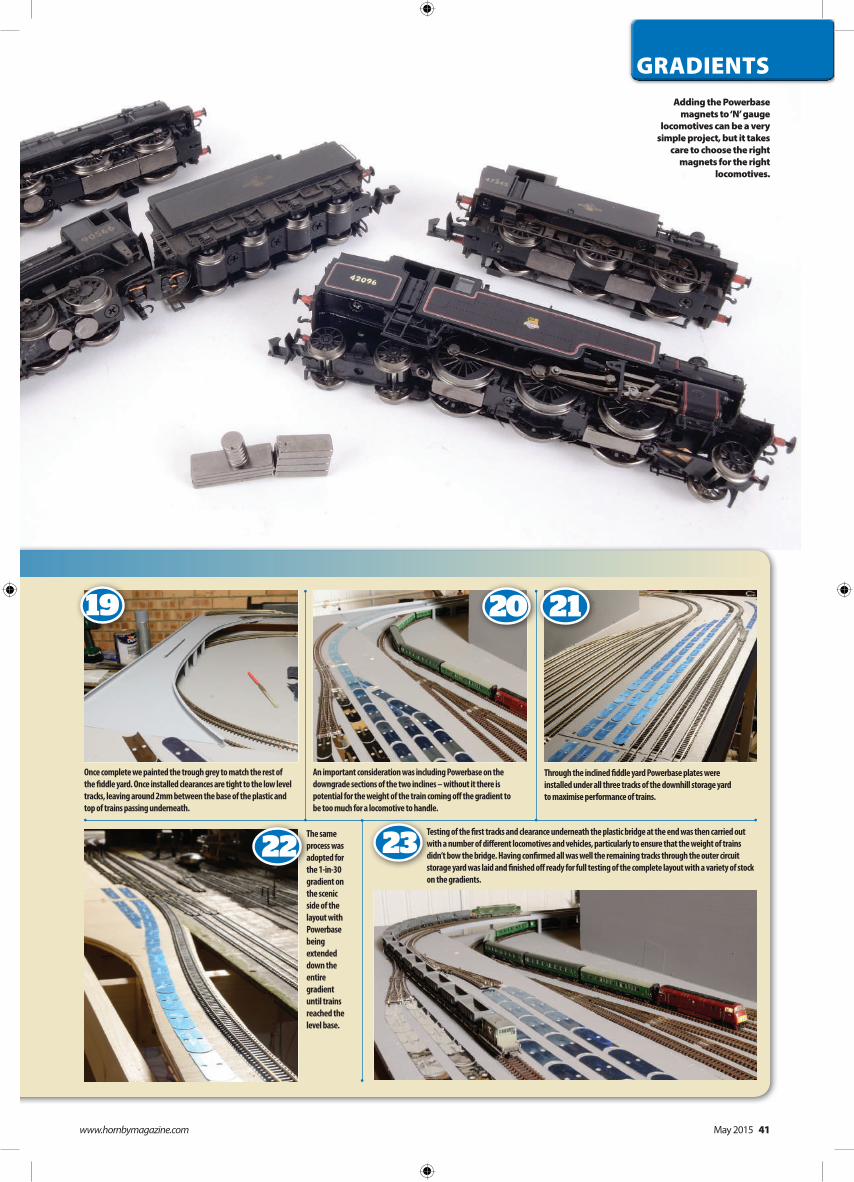
MAGNET FIXINGSOnce the track and plates are installed there is one final component required to complete the transformation which Powerbase can offer – fitting of NEO magnets to locomotives. Various packs are available to suit ‘OO’ and ‘N’ gauge locomotives together with fixing methods and products.
The closer to rail height the magnets are the better they will perform, but this can pose a problem with some locomotives where the height of the chassis base plate is a considerable distance from the rails. To accommodate this the plastic packing which contains the Powerbase magnets can be used or, alternatively, a set of etched brass frets can be obtained for use in certain circumstances.
In ‘N’ gauge fitting the magnets does call for ingenuity due to the very close proximity of some chassis base plates to the rails.
»»»Beginner
Intermediate
AdvancedSKILL LEVEL
7 8 9
10 12
11
To ensure a strong joint between the new strip of plywood on the lower level and the original board a bead of No More Nails adhesive was applied along its length to join the boards together. Screws were then inserted to fix the new strip to the cross braces.
With the extension for the level fiddle yard in place the inclined section was fitted in place for the final time. 4.0 35mm screws were used throughout to secure it to the risers.
To improve the appearance of the fiddle yard all of the original track was lifted so that the baseboard surface could be painted grey. This also sealed the baseboard surface.
With the lower level fiddle yard relaid – and now expanded from six to eight tracks – the pointwork for the inclined fiddle yard was mocked up. The aim is to build a six track fiddle yard on the gradient offering space for a minimum of 14 trains on this layout between the two yards.
Having lightly pinned the track in place to establish its position a pencil was used to draw a line around both sides of each running line where Powerbase plates would be installed. The plates themselves are the same width as ‘N’ gauge track and made of thin metal. A blue plastic cover marks the upwards face of the plates.
Next having prepared holes for point motors, the track was lifted and a bead
of PVA glue run round the centre of the previously
drawn pencil marks.
GRADIENTS
www.hornbymagazine.com May 2015 39
»
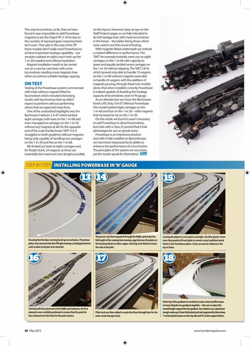
The only locomotives, so far, that we have found it near impossible to add Powerbase magnets to are the Dapol ‘9F’ 2-10-0s due to the number of exposed gears meaning there isn’t room. That said, in the case of the ‘9F’ these models don’t really need Powerbase to achieve impressive haulage capability – our samples waltzed an eight coach train up the 1-in-30 unaided and without hesitation.
Magnet installation needs to be carried out on a case by case basis with some locomotives needing more magnets than others to achieve suitable haulage capacity.
ON TESTTesting of the Powerbase system commenced with trials without magnets fitted to locomotives which revealed interesting results with locomotives that we didn’t expect to perform well out performing others that we expected more from.
One of the undoubted highlights was the Bachmann Fairburn 2-6-4T which tackled eight carriages with ease on the 1-in-68 and even managed six carriages on the 1-in-30 without any magnets at all! On the opposite end of the scale the Bachman ‘5MT’ 4-6-0 struggled on both gradients without magnets, being only capable of handling two carriages on the 1-in-30 and five on the 1-in-68.
We limited our tests to eight carriages and, for freight stock, 24 wagons, as these are essentially the maximum train lengths possible
on this layout. However, keep an eye on the Staff Projects pages as we fully intended to do full haulage tests with more locomotives in the future – the tables listing those which were used in our first round of testing.
With magnets fitted underneath we noticed a marked difference in performance. The ‘5MT’ for example instantly went out on eight carriages on the 1-in-68 with capacity to spare and equally tackled seven carriages on the 1-in-30 without slipping. The ‘WD’ 2-8-0s which proved only able to handle 10 wagons on the 1-in-68 without magnets were able to handle 24 wagons with the addition of magnets proving, through these two models alone, that when installed correctly Powerbase is indeed capable of doubling the haulage capacity of locomotives, even in ‘N’ gauge.
As an ultimate test we chose the Bachmann Farish LMS ‘Jinty’ 0-6-0T. Without Powerbase this model tackled eight carriages on the 1-in-68 and four on the 1-in-30 – with magnets that increased to six on the 1-in-30.
On the whole we found it wasn’t necessary to add Powerbase to diesel locomotives, but trials with a Class 25 proved that it had advantages for use on goods trains.
Powerbase is an impressive product and with it fully installed on Barrenthorpe we have been impressed by its ability to enhance the performance of a locomotive. The principles of the system are very basic, yet the results speak for themselves.
INSTALLING POWERBASE IN ‘N’ GAUGESTEP BY STEP
13 14 15
16 1817
Ensuring that the blue covering faced up on each piece, Powerbase plates were pressed onto the PVA glue leaving a small gap between each to allow track pins to be inserted.
The process was then repeated through the fiddle yard under the full length of the running lines leaving a gap between the plates at the baseboard joint to allow copper-clad strip to be fitted to secure the rails at the joint.
Leaving the plates to set in place overnight, the blue plastic covers were then peeled off each plate to reveal a smart polished metal finish to the Powerbase plates. Track can now be relaid over the top of them.
Starting with the pointwork at the fiddle yard entrance, the first elements were carefully positioned to ensure that the point tie bars returned over the holes for the point motors.
Plain track was then added to create the three through lines for the outer circuit storage tracks.
At the top of the gradient we needed to create a lower profile means of connecting the two gradients together – this was to reduce the overall height required for the gradient. Our solution was a plasticard trough made up of 2mm thick plasticard and supported by 8mm deep ‘I’ section plastic beams on the top side and ‘H’ section support below.
40 May 2015 www.hornbymagazine.com
GRADIENTS
19 20 21
22 23
Once complete we painted the trough grey to match the rest of the fiddle yard. Once installed clearances are tight to the low level tracks, leaving around 2mm between the base of the plastic and top of trains passing underneath.
An important consideration was including Powerbase on the downgrade sections of the two inclines – without it there is potential for the weight of the train coming off the gradient to be too much for a locomotive to handle.
Through the inclined fiddle yard Powerbase plates were installed under all three tracks of the downhill storage yard to maximise performance of trains.
The same process was adopted for the 1-in-30 gradient on the scenic side of the layout with Powerbase being extended down the entire gradient until trains reached the level base.
Testing of the first tracks and clearance underneath the plastic bridge at the end was then carried out with a number of different locomotives and vehicles, particularly to ensure that the weight of trains didn’t bow the bridge. Having confirmed all was well the remaining tracks through the outer circuit storage yard was laid and finished off ready for full testing of the complete layout with a variety of stock on the gradients.
Adding the Powerbase magnets to ‘N’ gauge
locomotives can be a very simple project, but it takes
care to choose the right magnets for the right
locomotives.
www.hornbymagazine.com May 2015 41