graduate institute of precision engineering, national...
TRANSCRIPT

1
A miniature hydro energy generator based on pressure fluctuation in Kármán vortexstreet
Dung-An Wang, Chia-Wei Chao and Jyun-Hua Chen
Graduate Institute of Precision Engineering, National Chung Hsing University, Taichung40227, Taiwan, ROC
Abstract
A new miniature hydro energy generator for harnessing energy from Kármán vortex
street behind a bluff body in a water flow is developed. Flow energy is converted into
electrical energy by an assembly of a cantilevered piezoelectric beam and a flexible
diaphragm. An analytical design method for the energy harvester is developed.
Prototypes of the energy generator are fabricated and tested. Experimental results show
that an open circuit output voltage of 120 ppmV and an instantaneous output power of 0.7
nW are generated when the pressure oscillates with an amplitude of nearly 0.3 kPa and a
frequency of about 52 Hz.
Keywords: Piezoelectric; Hydro energy generator; Kármán vortex street
____________
* Corresponding author. Tel.:+886-4-22840531; fax:+886-4-22858362
E-mail address: [email protected] (D.-A. Wang).
1. Introduction
In recent years a considerable effort was focused on use of renewable energy
coming from natural resources such as flowing water, rain, tides, wind, sunlight,

2
geothermal heat and biomass. The renewable energy of small-scale hydro (Malla et al.,
2011), modern biomass, wind, solar, geothermal and biofuels accounted for 2.7% of
global final energy consumption in 2008 and are growing very rapidly (REN21, 2010).
Recently, development of wireless sensor network for industrial process monitoring and
control, machine health monitoring (Okamoto et al., 2009), environment and habitat
monitoring, healthcare applications, home automation, and traffic control demands an
economical source of energy without supply of fuel and replacement of finite power
sources. Combination of small hydro systems with photovoltaic solar systems may
provide a solution to this need because in many areas, water flow, and thus available
hydro power, is highest in rainy days when solar energy is at a minimum.
Small hydro systems using turbines/wheels can be used to convert mechanical
energy from water flow into electricity (Lyshevski, 2011). Krähenbühl et al. (2009)
designed an electromagnetic generator based on a turbine driven by water pressure drop
in throttling valves and turbo expanders in plants that output a power of 150 W with a
rotation speed of 490000 rpm. Their device comprises a turbine and a permanent
generator. A detailed electromagnetic machine design, rotor dynamics analysis and a
thermal design were required to construct their energy generator. Holmes et al. (2005)
reported an electromagnetic generator integrated with a microfabricated axial-flow
microturbine. The power output of the fabricated microdevice can be as high as 1.1 mW
per stator when operated at a rotation speed of 30000 rpm, but the fabrication processes
for their prototype involve deep reactive ion etching, multilevel electroplating, SU8
processing and laser micromachining. Herrault et al. (2008) presented a rotary
electromagnetic generator to harvest the mechanical energy of an air-driven turbine. The

3
fabrication of their device requires electroforming, magnet demagnetization and laser
machining. A maximum output power of 6.6 mW is attained, when their device is driven
at a rotation speed of 392000 rpm by an air turbine. The devices of Krähenbühl et al.
(2009), Holmes et al. (2005) and Herrault et al. (2008) require elaborate techniques for
fabrication of their stator-rotor subcomponents and high rotation speeds for efficient
energy harvesting. A device with simpler structure design and ease of application may be
needed to extract energy from fluid motion.
The installation with micro/meso pipeline systems may provide an alterntive for
harvesting small scale water flow energy. Sanchez-Sanz et al. (2009) accessed the
feasibility of using the unsteady forces generated by the Kármán street around a micro-
prism in the laminar flow regime for energy harvesting. They presented design
guidelines for their devices, but fabrication and experiments of the proposed device are
not shown in their work. Allen and Smits (2001) used a piezoelectric membrane placed
behind the Kármán vortex street formed behind a bluff body to harvest energy from fluid
motion. They examined the response of the membrane to vortex shedding. The power
output of the membrane is not presented. Taylor et al. (2001) developed an eel structure
of piezoelectric polymer to convert mechanical flow energy to electrical power. They
have focused on characterization and optimization of the individual subsystems of the eel
system with a generation and storage units in a wave tank. Design and deployment of the
eel system need further investigation. Tang et al. (2009) designed a flutter-mill to
generate electricity by extracting energy from fluid flow. Their structure is similar to the
eel systems of Allen and Smits (2001) and Taylor et al. (2001). They investigate the
energy transfer between the structure and the fluid flow through an analytical approach.

4
These authors utilized the flow-induced vibrations of fluid-structure interaction system to
extract energy from the surrounding fluid flow (Blevins, 1990). The eel structures of
Allen and Smits (2001), Taylor et al. (2001) and Tang et al. (2009) have the potential to
generate power from milli-watts to many watts depending on system size and flow
velocity, but a power-generating eel has not been demonstrated.
Recent interests in energy harvesting from Kármán streets have prompted new
developments of energy generators. Akaydınet al. (2010a) placed a piezoelectric beam
in the wake of a circular cylinder in a wind tunnel for energy harvesting. They found that
the maximum power output was measured when the tip of the beam is about two
diameters downstream of the cylinder. A coupled simulation that takes into account the
aerodynamics, structural vibration and electrical response of a piezoelectric beam in the
wake of a circular cylinder in unsteady, turbulent fluid was developed by Akaydınet al.
(2010b). Akaydin et al. (2010c) reported a piezoelectric beam with a cylindrical tip body
which promotes sustainable, self-excited vibration for energy harvesting. 0.24 mW of
electrical power can be attained with their harvester in a uniform flow of 28 m/s. De
Marqui et al. (2010) presented a piezoaeroelastic model for a cantilevered wing energy
harvester. They investigated electrical power output and the displacement of the wing for
various airflow speeds and different electrode configurations.
In this paper, a new device for energy harvesting from pressure fluctuation in
Kármán vortex street is developed, where a piezoelectric film is placed on top of a
flexible diaphragm, which is located in the wake of a bluff body. The piezoelectric film
oscillates with the flexible diaphragm due to the vortices shed from the bluff body in a
water flow. As illustrated in Figure 1(a), a flow channel with a flexible diaphragm is

5
connected to a flow source. A piezoelectric film of a cantilever type is glued to a bulge
affixed to the top surface of the flexible diaphragm. A bluff body is placed in the flow
channel. Pressure in the flow channel behind the bluff body may fluctuate with the same
frequency as the pressure variation caused by the Kármán vortex street. Figure 1(b)
shows that the pressure in the channel causes the diaphragm and the piezoelectric film to
deflect in the upward direction. As the pressure increases to the maximum, the
diaphragm reaches its highest position (Figure 1(c)). When the pressure drops, the
diaphragm and the piezoelectric film deflect downward (Figure 1(d)). As the pressure
decreases to the minimum, the diaphragm reaches its lowest position (Figure 1(e)). Thus,
by connecting the energy generator to an ambient flow source, the oscillating movement
of the diaphragm with the cantilever piezoelectric film attached to it makes the energy
harvesting possible.
The focus of this paper is on the investigation of energy extraction from vibration
induced by the Kármán vortex street behind a bluff body in a water flow. In order to
access the feasibility of the proposed energy generator, analytical models are derived to
evaluate the design of the energy harvester. Fabrication of the energy generator with a
molding process and an assembly technique is described. Experimental setup used to
measure the pressure in the flow channel, the deflection and voltage output of the device
is reported. The experimental results are compared with the results of the analyses.
2. Design
A piezoelectric energy generator is shown in Figure 2(a). The variation of the
water pressure in the channel drives a polydimethylsiloxane (PDMS) diaphragm and a
6
cantilever piezoelectric film into vibration. The vibration energy is converted to
electrical energy by the piezoelectric film (Howells, 2009). Usage of vibration energy to
apply strain energy to the piezoelectric material is an effective method of implementing a
power harvesting system (Sodano et al., 2004; Erturk and Inman, 2011). While there are
a number of schemes for harvesting ambient energy sources, piezoelectric materials can
be easily incorporated into many systems (Anton and Sodano, 2007). Figure 2(b) is an
exploded view of the energy generator. It consists of a flow channel, a bluff body, a
PDMS diaphragm bonded to the channel, and a piezoelectric film attached to the PDMS
diaphragm through a bulge made of acrylic blocks.
2.1 Kármán vortex street
This harvesting of flow energy via the formation of Kármán vortex street behind a
bluff body is related to the response of a flexible diaphragm to a periodical pressure
variation of water in a flow channel. Flow past a bluff body creates an unstable wake in
the form of alternating vortices and induces the periodic pressure variation (Violette et al,
2007). The frequency at which the vortices are shed from the bluff body is given by the
Strouhal number, St (Lord Rayleigh, 1915)
U/St (1)
where is the frequency of oscillating flow, is the characteristic length, and U is the
free-stream velocity. The shedding from a circular cylinder of diameter d immersed in a
steady flow occurs in the range 72 10Re10 , where Re is the Reynolds number, with
an average Strouhal number 21.0/ Ud (White, 1986).
Venugopal et al. (2011a) found out that trapezoidal bluff bodies are the most

7
appropriate shape in terms of differential pressure amplitude and deviation in Strouhal
numbers among the triangular, trapezoidal, circular, ring-type, and conical cylinders. For
a trapezoidal bluff body, the Strouhal number is given as (Chung and Kang, 2000)
UH /St 1 (2)
where 1H is the height of the front side of the trapezoidal cylinder. The front height 1H
and rear height 2H of the trapezoidal cylinder are indicated in Figure 2(a). Chung and
Kang (2000) found that the values of the St for vortex shedding behind trapezoidal
cylinders for a blockage ratio of 0.02 and low Reynolds numbers, 002Re100 , ranges
from 0.14 to 0.16. Sun et al. (2007) investigated wake flow behind trapezoidal bluff
body with a blockage ratio of 0.36. The value of St based on the work of Sun et al. (2007)
is nearly 0.25 for 43 1048.8Re109.42 (Venugopal et al., 2011b). Venugopal et al.
(2011a) carried out experimental investigations of vortex shedding behind a trapezoidal
bluff body with a blockage ratio of 0.28. The measured St value is 0.24 for
55 101.2Re101.2 .
The device considered here has the flow inside a channel in the presence of a bluff
body. The vortex shedding frequency detected at the channel wall may increase as the
blockage ratio increases (Miau and Hus, 1992). Anagnostopoulos and Iliadis (1996),
Zovatto and Pedrizzetti (2001) and Sahin and Owens (2004) reported this phenomenon
based on numerical investigations of flow about circular cylinders. Venugopal et al.
(2010) investigated the effects of three blockage ratios (0.14, 0.24 and 0.3) on the vortex
shedding from a trapezoidal bluff body by experiments. The reported values of St for
400Re200 are nearly 0.15, 0.21 and 0.27 for the three blockage ratios, 0.14, 0.24
and 0.3, respectively. The maximum blockage ratio is selected due to the large pressure

8
loss at high blockage ratios (Venugopal et al., 2010).
Williamson (1996) stated that a vortex grows in strength until a new vortex forms
behind the bluff body, which implies that the point with a maximum velocity fluctuation
is half a wavelength downstream of the bluff body. The location with a maximum
pressure fluctuation can be assumed as the point with maximum velocity fluctuation for
engineering applications. Therefore, the length of the flexible diaphragm can be taken as
a wavelength , which may be approximated by fU / . Zheng et al. (2007) also found
that the position of the shed vortex with strongest strength is approximately half a
wavelength from the trapezoidal body based on their numerical studies. The diaphragm
center is positioned nearly at a half wavelength downstream the bluff body in this
investigation.
An estimation of the pressure amplitude is needed in order to predict the
amplitude of the diaphragm vibration. A nonlinear model of the pressure fluctuation P
may be assumed to have the form (Monkewitz, 1996)
2/1)Re(Re critcP (3)
where c is a constant and critRe is a critical Reynolds number. This equation is derived
by a linearization of a steady state amplitude solution of a Stuart-Landau nonlinear model
equation for the amplitude of wake oscillations (Williamson, 1996).
2.2 A model for estimation of the voltage output
Figure 3(a) shows a schematic of the flexible diaphragm, the bulge, and the
piezoelectric film. A pressure P is applied at the bottom surface of the diaphragm. A
Cartesian coordinate system is shown in the figure. Figure 3(b) is a cantilever beam
9
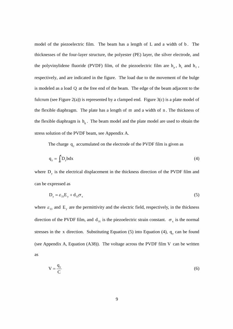
model of the piezoelectric film. The beam has a length of L and a width of b . The
thicknesses of the four-layer structure, the polyester (PE) layer, the silver electrode, and
the polyvinylidene fluoride (PVDF) film, of the piezoelectric film are ph , sh and fh ,
respectively, and are indicated in the figure. The load due to the movement of the bulge
is modeled as a load Q at the free end of the beam. The edge of the beam adjacent to the
fulcrum (see Figure 2(a)) is represented by a clamped end. Figure 3(c) is a plate model of
the flexible diaphragm. The plate has a length of m and a width of n . The thickness of
the flexible diaphragm is gh . The beam model and the plate model are used to obtain the
stress solution of the PVDF beam, see Appendix A.
The charge yq accumulated on the electrode of the PVDF film is given as
L
yy bdxDq0
(4)
where yD is the electrical displacement in the thickness direction of the PVDF film and
can be expressed as
xyy dED 3133 (5)
where 33 and yE are the permittivity and the electric field, respectively, in the thickness
direction of the PVDF film, and 31d is the piezoelectric strain constant. x is the normal
stresses in the x direction. Substituting Equation (5) into Equation (4), yq can be found
(see Appendix A, Equation (A38)). The voltage across the PVDF film V can be written
as
Cq
V y (6)
10
where C is the capacitance of the PVDF film. The natural frequency of the device n
can be estimated by
Mkkn /21 (7)
where 1k and 2k are the stiffness of the PVDF film and the PDMS diaphragm,
respectively, and M is the combined mass of the PVDF film, the rigid bulge and the
PDMS diaphragm. Expressions of 1k and 2k can be found in Appendix A, Equation
(A32) and Equation (A41), respectively. The simple quasi-static model is presented here
for low-frequency applications and initial evaluation of the device. Comprehensive
models for unimorph and bimorph cantilevered piezoelectric harvesters are derived by
Erturk and Inman (2008) and Erturk and Inman (2009), respectively. Expressions for
coupled mechanical response, voltage, current, and power outputs are presented in their
works.
2.3 Analysis
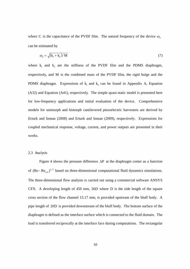
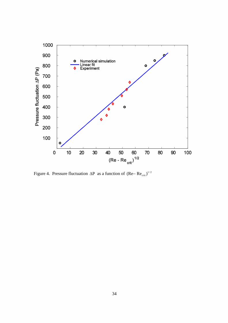
Figure 4 shows the pressure difference P at the diaphragm center as a function
of 2/1)Re(Re crit based on three-dimensional computational fluid dynamics simulations.
The three-dimensional flow analysis is carried out using a commercial software ANSYS
CFX. A developing length of 450 mm, D30 where D is the side length of the square
cross section of the flow channel 15.17 mm, is provided upstream of the bluff body. A
pipe length of D20 is provided downstream of the bluff body. The bottom surface of the
diaphragm is defined as the interface surface which is connected to the fluid domain. The
load is transferred reciprocally at the interface face during computations. The rectangular

11
interface surface is clamped at its four edges and allowed to deflect under the pressure
from the fluid domain.
In the analysis, a uniform pressure is applied at the inlet of the flow channel. This
inlet pressure is adjusted to match the desired uniform velocity profile at the inlet along
the direction of the inlet flow. No-slip (zero velocity) conditions all along the channel
walls are specified. It is assumed that only the relative value of pressure is important, and
a zero pressure is applied at the outlet of the channel. A moving mesh boundary
condition is imposed along the fluid-structure interface. The three-dimensional model
with the dimensions indicated in Figure 2 is considered. The turbulent flow is simulated
with the shear stress transport (SST) model of ANSYS CFX software. The three-
dimensional fluid model is solved by using the continuity equation and the momentum
equations (White, 1986). The equations are discretized using a second upwind scheme.
The time duration and the time step size of the coupled analyses are taken as 0.5 sec, and
0.001 sec, respectively. We divide one period of the vortex shedding into at least 200
time steps. The transient solutions usually reach steady state after 20 periods of the
vortex shedding.
The PVDF diaphragm is modeled as shell elements, SHELL181. The diaphragm
support structures are models as solid structural elements, SOLID45. The fluid, water, is
considered incompressible and is assumed to have no dependence on the temperature
change. The fluid model has 35456 hexahedral elements. The material properties and
dimensions of the laminated piezoelectric film (LDT0-028K/L, Measurement Specialties,
Inc., US) are listed in Table 1. The material properties and dimensions of the film are
provided by the manufacturers. The Young’s modulus gE and Poisson’s ratio g of the
12
PDMS diaphragm are taken as 3 MPa and 0.5, respectively, based on a measured
engineering stress - engineering strain curve of the material. The PDMS diaphragm has a
thickness of 200 μm and a density of 1670 3kg/m . The mass of the bulge is 0.24 g.
The Reynolds number of the flow channel can be determined by
/Re 1HU (8)
where U is the flow velocity at the inlet of the device, is the dynamic viscosity of the
water, 310002.1 secPa , and 1H is the height of the front side of the trapezoidal
cylinder. The Reynolds number is calculated in order to determine if the analysis is in
the turbulent region. As shown in Figure 4, a linear fit of the pressure fluctuation at the
diaphragm center is obtained with 09.11c and 1813Re crit . Experimental results are
also shown in the figure. The result is consistent with the linearization of the Stuart-
Landau nonlinear model equation for the amplitude of wake oscillations. Based on the
coupled fluid-structure simulations, the amplitude of the pressure fluctuation at the grid
point just below the diaphragm center is nearly the same as that at the grid point in the
bottom plate of the flow channel, opposite to the diaphragm center. The simulated
pressure fluctuations at these two grid points are out of phase with each other. The
motion of the diaphragm may not impact the vortex shedding for the inlet flow velocities,
0.43 m/sec, 1.06 m/sec, 1.52 m/sec, 1.75 m/sec, and 2.02 m/sec, considered in the
simulations.
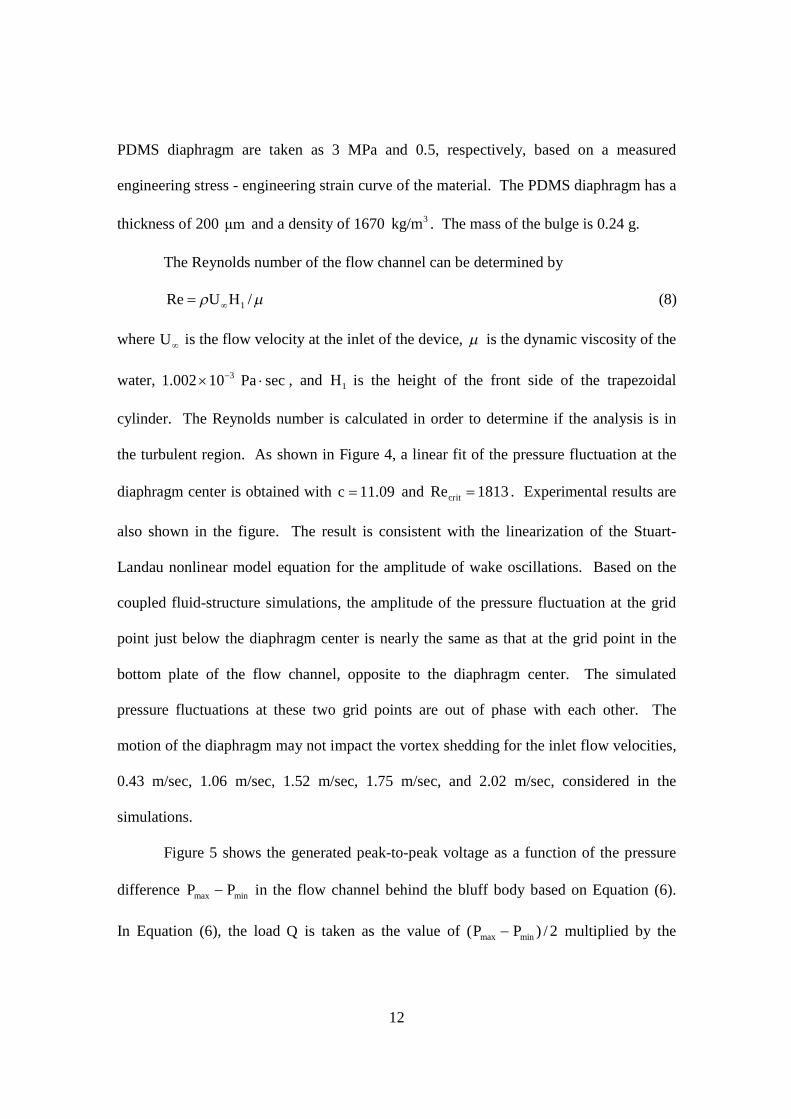
Figure 5 shows the generated peak-to-peak voltage as a function of the pressure
difference minmax PP in the flow channel behind the bluff body based on Equation (6).
In Equation (6), the load Q is taken as the value of 2/)( minmax PP multiplied by the

13
effective PDMS area, mm17.15mm40 (see Figure 2(b)). The range of the pressure
loads considered is based on the measured pressures in the flow channel of a fabricated
prototype. The peak-to-peak voltage increases linearly as the pressure difference
increases, since the behaviors of the materials are assumed to be linear elastic in the beam
model. For the pressure difference ranging from 0 to 0.7 kPa, the maximum of the
generated peak-to-peak voltage is 124 mV.
3. Fabrication, experiments and discussions
3.1 Fabrication
In order to verify the effectiveness of the proposed energy harvesting device,
prototypes of the energy generator are fabricated. The PDMS diaphragm is fabricated by
a molding process in an acrylic mold. First, an acrylic mold is carved by a milling
machine (PNC-3100, Roland DGA Co., Japan). Next, the PDMS material is poured over
the mold. The PDMS material is composed of two parts, a curing agent and the polymer.
They are mixed with a volume ratio of 1:10. Before pouring into the mold, the mixture is
degassed under vacuum until no bubbles appear. The PDMS is cured at C80o for 40
minutes. Then, the PDMS is peeled off from the mold.
The energy generator is assembled using glue. The walls, the top plate and the
bottom plate of the flow channel are manufactured by a milling machine. First, the walls
are glued to the bottom plate as shown in Figure 2(b). Next, the bluff body is affixed to
the walls. Then, the top plate of the flow channel with an embedded PDMS diaphragm is
attached to the top surface of the walls. Subsequently, an acrylic bulge is glued to the
center of the PDMS diaphragm, and an acrylic anchor is glued to an edge surface of the

14
top plate to provide a support of the PVDF film. Finally, the PVDF film is glued to the
bulge and the acrylic anchor by applying an adhesive (3M Scotch) to complete the
assembly steps. Figure 6 is a photo of an assembled energy generator.
3.2 Experiments
Figure 7 is a photo of the experimental apparatus for testing of the fabricated
device. The energy generator is placed on an optical table for vibration isolation. From
the bottom of a storage tank, an inlet pipe is run down to the inlet of the energy generator.
The water level in the storage tank is kept constant for a steady water flow at the inlet of
the flow channel. Using gravity, water is forced into the inlet of the energy generator.
Tap water is pumped into the storage tank through a pump located in a recycle tank. An
outlet pipe extending between the outlet of the energy generator and the recycle tank
provides a continuous supply of water. Figure 8 is a schematic of the measurement
apparatus. The oscillating deflection of the piezoelectric film is measured by a fiberoptic
displacement sensor (MTI-2000, MTI Instruments Inc., US). The generated voltage of
the piezoelectric film is recorded and analyzed by a data acquisition unit (PCI-5114,
National Instruments Co., US). The pressure in the flow channel is measured with a
subminiature pressure sensor (PS-05KC, Kyowa Electronic Instruments Co. Ltd., Japan)
embedded in the bottom plate of the flow channel, nearly 8 mm behind the bluff body
and opposite to the flexible diaphragm. The pressure sensor is connected to a data
acquisition unit (DBU-120A, Kyowa Electronic Instruments Co. Ltd., Japan).
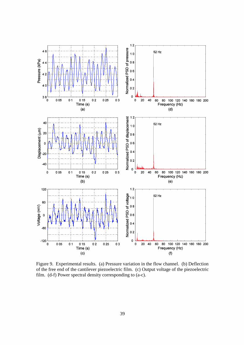
A typical experimental result is shown in Figure 9. Figure 9(a) shows the
pressure history in the flow channel behind the bluff body, where the pressure oscillates
15
with an average amplitude of nearly 0.3 kPa and a frequency of 52 Hz. The measured
deflection history of the free end of the piezoelectric film is shown in Figure 9(b). The
film oscillates with an average amplitude of about 20 μm. The measured open circuit
voltage generated by the piezoelectric film is shown in Figure 9(c). The output peak-to-
peak voltage is nearly 120 ppmV in average. The time history of the experimental results
are considered typical of the measurements in a duration of 20 seconds. Figures 9(d-f)
are the power spectral density corresponding to Figures 9(a-c), respectively, but are based
on series of the measurements in the duration of 20 seconds. Fast Fourier transform is
used to compute the power spectral density. The frequency window of the spectra is 0.17
Hz. It can be seen from Figures 9(d-f) that there is one obvious peak value of 52 Hz. It
is evident that the same peak values shown in Figures 9(d-f) are caused by the pressure
fluctuation in the flow channel. The low frequency noise, below 20 Hz, observed in
Figures 9(d-f) can be attributed to the fact that the flows of the experimental setup are
always contaminated by ambient noise sources, and the geometry of the bluff body and the
walls of the flow channel are not perfectly symmetric and smooth.
The average free-stream velocity U of the experiment shown in Figure 9 is 1.08
m/sec. The Reynolds number Re of the flow determined by Equation (8) is 41064.1 ,
which is turbulent. The frequency of the pressure fluctuation is nearly 52 Hz, see Figure
9(d), at which the vortices are shed from the bluff body. Using the front height 1H = 4.25
mm (see Figure 2), U =1.08 m/sec and Equation (2), the corresponding value of St is
estimated as 0.20. The blockage ratio of the device is 0.28 (see Figure 2(b)). The
estimated value of St, 0.20, is close to that reported by Venugopal et al. (2011a), 0.24 for
vortex shedding behind a trapezoidal bluff body with a blockage ratio of 0.28 and
16
55 101.2Re101.2 . Figure 10 shows the experimental St numbers as a function of
the free stream velocities. The St numbers are nearly 0.2 for the free stream velocities
ranging from 0.70 to 1.16 m/sec.
Figure 4 shows the experimental pressure fluctuation at the diaphragm center.
The results are consistent with the Stuart-Landau model equation of Equation (3) with
09.11c and 1813Re crit based on the coupled fluid-structure simulations.
Experimental results are also shown in Figure 5, where the free stream velocity is varied,
and the output voltage and the pressure difference are recorded. The output voltage
increases nearly linearly as the pressure difference increases. Compared to the
experimental output voltages at the various pressures, the calculated output voltages
based on the analytical solution of Equation (6), can be considered acceptable. The
higher output voltage of the experiments can be attributed to the uncertainties of the
material properties, assembly tolerances, and part misalignment.
In order to evaluate the harvesting system, experiments on the electrical power
output of the device are performed. A matched load is connected to the device to
maximize output power. The internal electrical resistance of the device is measured by a
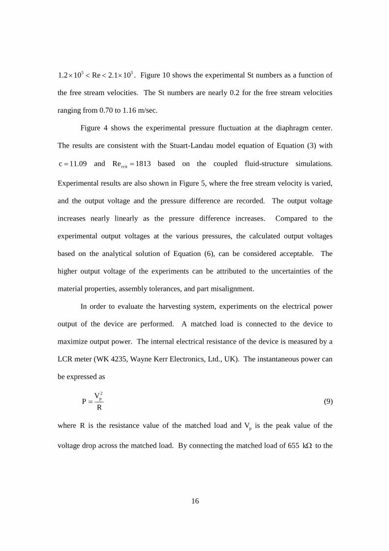
LCR meter (WK 4235, Wayne Kerr Electronics, Ltd., UK). The instantaneous power can
be expressed as
R
VP p
2
(9)
where R is the resistance value of the matched load and pV is the peak value of the
voltage drop across the matched load. By connecting the matched load of 655 k to the
17
device and detecting the peak voltage drop across the matched load, 21.1 mV , the
instantaneous power is determined as 0.7 nW .
The output power of the device is relatively low, given the structure design of the
flow channel, the bluff body and the cantilever piezoelectric film. In this investigation,
the device is operated at 52 Hz, which is much smaller than the natural frequency
Hz)911(n of the device, determined by Equation (7) based on a second order
approximation of the model. When the ambient excitation is at a single frequency, the
design of the energy harvesting device should be tailored to the ambient frequency
available. This investigation focuses on the feasibility of extracting fluid flow energy by
a linear-type harvester using vortex shedding from a bluff body. No attempt is made to
optimize the device to increase the power output. The novelty of this energy harvesting
approach is the installment of the simple piezoelectric energy conversion mechanism at
the top of the flow channel. This arrangement facilitates the potential of miniaturization
of the device using microfabrication, and avoids the need of complex device assembling
process. The reported works of energy harvesting from Kármán vortex street (Allen and
Smits, 2001; Taylor et al., 2001; Tang et al., 2009) have the eel-like structures placed
behind the bluff bodies, their devices may require elaborate multi-layered fabrication
rendering them unfeasible using microfabrication technologies.
4. Conclusions
A new linear-type piezoelectric energy generator based on flow induced vibration
is developed. The energy is harvested from Kármán vortex street behind a bluff body in
a water flow. The pressure oscillation due to the Kármán vortex street in the flow

18
channel of the generator results in a periodical deflection of the piezoelectric film and
therefore the voltage generation. An analytical model for estimation of the output voltage
of the device is developed for quick evaluation of the effects of device dimensions,
pressure loads and material properties on the performance of the energy generator.
Prototypes of the energy generator are fabricated and tested. The generated voltage and
instantaneous power of the device are approximately 0.12 ppV and 0.7 nW , respectively,
when the pressure oscillates with an amplitude of nearly 0.3 kPa and a frequency of about
52 Hz. This energy harvesting approach can be utilized to harvest fluid flow energy in
pipelines by immersing bluff bodies in pipes which cause pressure oscillation in Kármán
vortex street in order to provide power for monitoring systems of pipelines.
Acknowledgement
This work is financially supported by a grant from National Science Council,
Taiwan (Grant Number: NSC 99-2221-E-005-075). The authors would like to express
their appreciation to the National Center for High-Performance Computing (NCHC),
Taiwan for their assistance. Helpful discussions with Professor Jerry M. Chen of
National Chung Hsing University, Taiwan, R.O.C. are greatly appreciated.
19
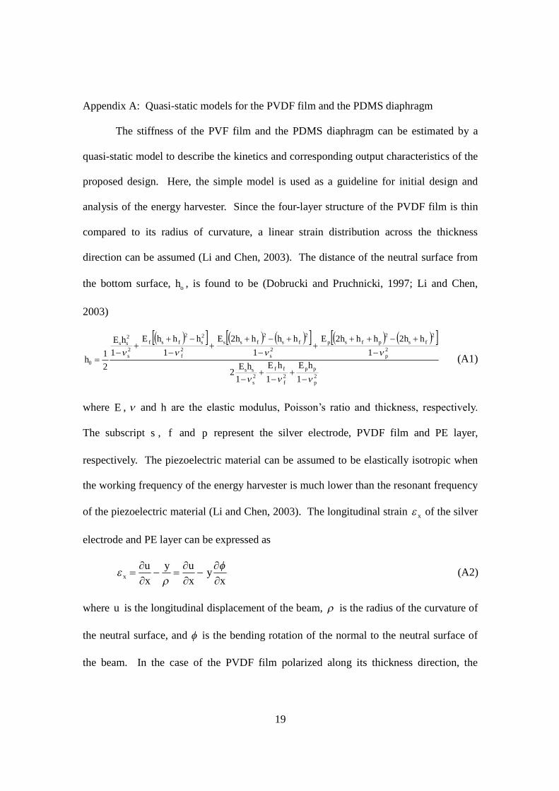
Appendix A: Quasi-static models for the PVDF film and the PDMS diaphragm
The stiffness of the PVF film and the PDMS diaphragm can be estimated by a
quasi-static model to describe the kinetics and corresponding output characteristics of the
proposed design. Here, the simple model is used as a guideline for initial design and
analysis of the energy harvester. Since the four-layer structure of the PVDF film is thin
compared to its radius of curvature, a linear strain distribution across the thickness
direction can be assumed (Li and Chen, 2003). The distance of the neutral surface from
the bottom surface, oh , is found to be (Dobrucki and Pruchnicki, 1997; Li and Chen,
2003)
222
2
22
2
22
2
22
2
2
0
1112
122
12
11
21
p
pp
f
ff
s
ss
p
fspfsp
s
fsfss
f
sfsf
s
ss
hEhEhE
hhhhhEhhhhEhhhEhE
h
(A1)
where E , and h are the elastic modulus, Poisson’s ratio and thickness, respectively.
The subscript s , f and p represent the silver electrode, PVDF film and PE layer,
respectively. The piezoelectric material can be assumed to be elastically isotropic when
the working frequency of the energy harvester is much lower than the resonant frequency
of the piezoelectric material (Li and Chen, 2003). The longitudinal strain x of the silver
electrode and PE layer can be expressed as
xy
xuy
xu
x
(A2)
where u is the longitudinal displacement of the beam, is the radius of the curvature of
the neutral surface, and is the bending rotation of the normal to the neutral surface of
the beam. In the case of the PVDF film polarized along its thickness direction, the
20
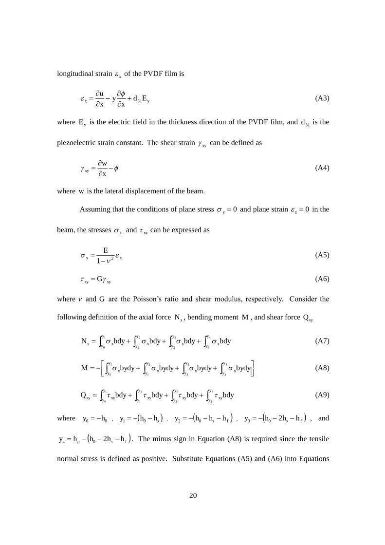
longitudinal strain x of the PVDF film is
yx Edx
yxu
31
(A3)
where yE is the electric field in the thickness direction of the PVDF film, and 31d is the
piezoelectric strain constant. The shear strain xy can be defined as
xw
xy (A4)
where w is the lateral displacement of the beam.
Assuming that the conditions of plane stress 0y and plane strain 0z in the
beam, the stresses x and xy can be expressed as
xxE
21 (A5)
xyxy G (A6)
where and G are the Poisson’s ratio and shear modulus, respectively. Consider the
following definition of the axial force xN , bending moment M , and shear force xyQ
4
3
3
2
2
1
1
0
y
y x
y
y x
y
y x
y
y xx bdybdybdybdyN (A7)
4
3
3
2
2
1
1
0
y
y x
y
y x
y
y x
y
y x bydybydybydybydyM (A8)
4
3
3
2
2
1
1
0
y
y xy
y
y xy
y
y xy
y
y xyxy bdybdybdybdyQ (A9)
where 00 hy , shhy 01 , fs hhhy 02 , fs hhhy 203 , and
fsp hhhhy 204 . The minus sign in Equation (A8) is required since the tensile
normal stress is defined as positive. Substitute Equations (A5) and (A6) into Equations
21
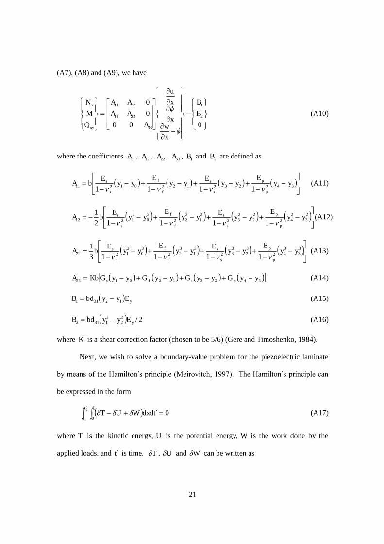
(A7), (A8) and (A9), we have
00000
2
1
33
2212
1211
BB
xw
x
xu
AAAAA
QMN
xy
x
(A10)
where the coefficients 11A , 12A , 22A , 33A , 1B and 2B are defined as
34223212201211 1111
yyE
yyE
yyE
yyE
bAp
p
s
s
f
f
s
s
(A11)
2
3242
22
232
21
222
20
21212 11112
1yy
Eyy
Eyy
Eyy
EbA
p
p
s
s
f
f
s
s
(A12)
3
3342
32
332
31
322
30
31222 11113
1yy
Eyy
Eyy
Eyy
EbA
p
p
s
s
f
f
s
s
(A13)
3423120133 yyGyyGyyGyyGKbA psfs (A14)
yEyybdB 12311 (A15)
2/22
21312 yEyybdB (A16)
where K is a shear correction factor (chosen to be 5/6) (Gere and Timoshenko, 1984).
Next, we wish to solve a boundary-value problem for the piezoelectric laminate
by means of the Hamilton’s principle (Meirovitch, 1997). The Hamilton’s principle can
be expressed in the form
2
1 00
t
t
LtdxdWUT (A17)
where T is the kinetic energy, U is the potential energy, W is the work done by the
applied loads, and tis time. T , U and W can be written as

22
32121 2IuIwwIuIuIT (A18)
wx
Qx
Mu
xN
U xyx
222(A19)
LxwQW
(A20)
where 4
0
),,1(),,( 2321
y
ydyyybIII . is the mass density of each layer.
Carrying out various variational operations yields
211
2
2
122
2
11 2 IuIxB
xA
xu
A
(A21)
322
332
2
222
2
12 22 IuIxB
xw
Ax
Axu
A
(A22)
wIxx
vA 12
2
33 2
(A23)
together with its appropriate boundary conditions
0at,0,0,0 xwu (A24)
LxQLxw
ABx
Axu
ABx
Axu
A
at,2,0,0 332221211211 (A25)
Considering the quasi-static case and constant properties along the beam yields
02
2
122
2
11
xA
xu
A
(A26)
0332
2
222
2
12
xw
Ax
Axu
A (A27)
02
2
33
xxv
A
(A28)
Solving Equations (A24-A28), we obtain

23
x
AAABABAQLA
xAAA
QLAxu
2211212
1222122
122
2211212
12 2
(A29)
xAQL
xAAA
BABAQLAx
AAAQLA
xw33
2
2211212
1122112
113
2211212
11 22
23
(A30)
x
AAABABAQLA
xAAA
QLAx
2211212
1122112
112
2211212
11 2
(A31)
Manipulating Equation (A30), the stiffness ))(/(1 LwQk of the PVDF film is given as
2
33112211212
22211
21233
1 323
LAAAAALAAAA
k
(A32)
Substituting Equations (A2), (A29) and (A31) into Equation (A5), we find the stress x
2211212
1222122
12
2211212
122
221 AAA
BABAQLAx
AAAQLAE
x
2211212
1122112
11
2211212
11 22AAA
BABAQLAx
AAAQLA
y (A33)
For energy harvesting applications, 0yE , therefore, 021 BB . x can be
written as
),(1
22221 2
2211212
21111
2211212
21212
2 yxQE
AAALALxA
yAAA
LALxAQE
f
f
f
fx
(A34)
where ),( yx represents the expression inside the bracket of Equation (A34). The
charge yq accumulated on the electrode of the PVDF film can be written as
L
f
fL
x
L
yy dxyxQE
bdbdxdbdxDq02310 310
),(1
(A35)
Some models of induced strain actuation of beam-like intelligent structures have
been developed by Crawley and Anderson (1990) and Shu and Lien (2006). Yang and
24
Ye (2009) reported a closed-form solution of interfacial stresses in beams. A simplified
version of their solution is needed so that a design-orientated model can be established.
Elvin and Elvin (2009) presented an equivalent circuit model for a piezoelectric generator.
Their circuit model needs to be validated by formulation of electromechanical equations
for the device considered.
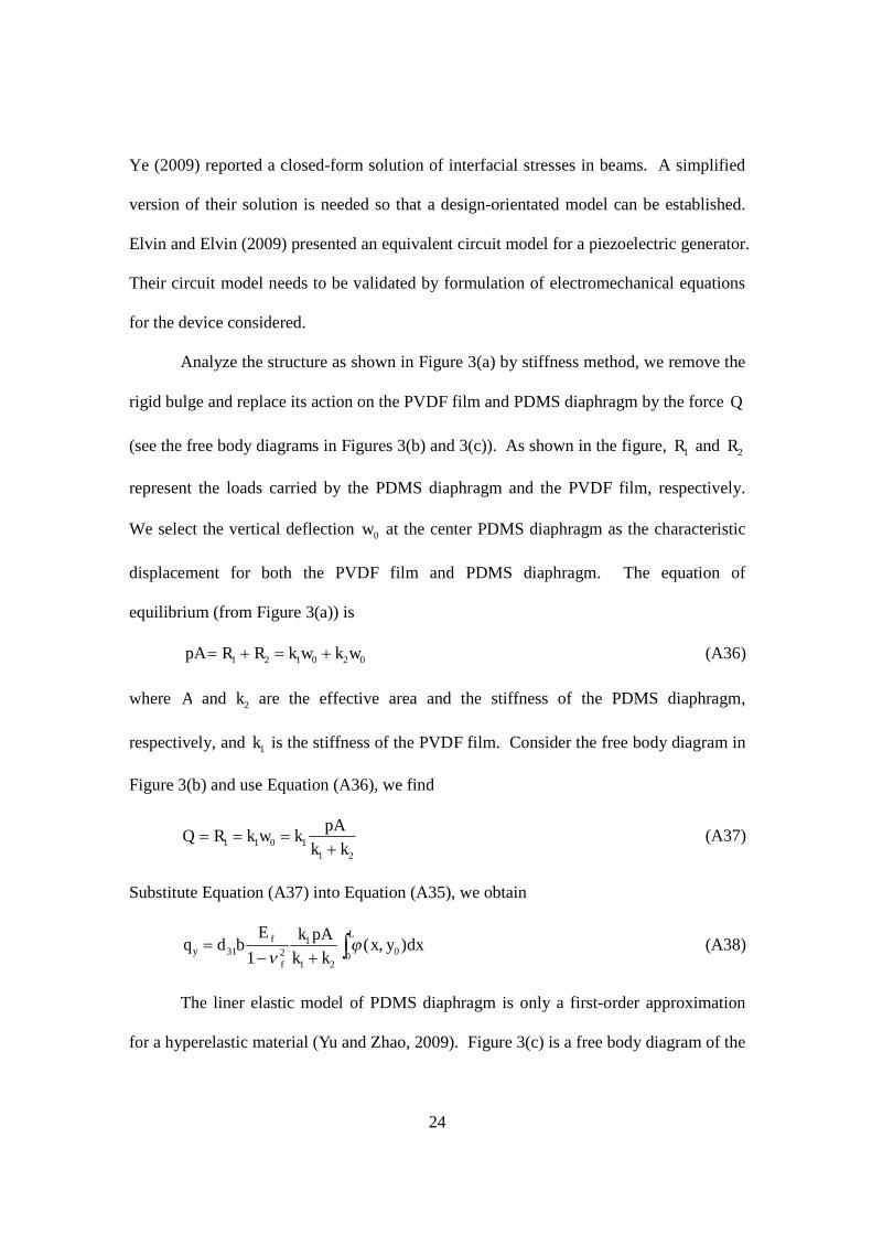
Analyze the structure as shown in Figure 3(a) by stiffness method, we remove the
rigid bulge and replace its action on the PVDF film and PDMS diaphragm by the force Q
(see the free body diagrams in Figures 3(b) and 3(c)). As shown in the figure, 1R and 2R
represent the loads carried by the PDMS diaphragm and the PVDF film, respectively.
We select the vertical deflection 0w at the center PDMS diaphragm as the characteristic
displacement for both the PVDF film and PDMS diaphragm. The equation of
equilibrium (from Figure 3(a)) is
020121 wkwkRRpA (A36)
where A and 2k are the effective area and the stiffness of the PDMS diaphragm,
respectively, and 1k is the stiffness of the PVDF film. Consider the free body diagram in
Figure 3(b) and use Equation (A36), we find
211011 kk
pAkwkRQ
(A37)
Substitute Equation (A37) into Equation (A35), we obtain
L
f
fy dxyx
kkpAkE
bdq0 0
21
1231 ),(
1
(A38)
The liner elastic model of PDMS diaphragm is only a first-order approximation
for a hyperelastic material (Yu and Zhao, 2009). Figure 3(c) is a free body diagram of the

25
diaphragm under the pressure load P due to the vortex street, the load Q due to the
removal of the rigid bulge, and the reaction force 2R due to the clamped edges. m , n
and gh represent the length, width and the thickness of the diaphragm, respectively. It is
assumed that the pressure load P is uniformly distributed. The effects of the load Q can
be neglected in order to estimate the stiffness of the diaphragm. Using Ritz’s method
(Timoshenko and Woinowsky-Krieger, 1959), the deflection of the diaphragm center 0w
with clamped edges is derived as
)4
143
43
(4 334
0
mnnm
mn
D
mnPw
g
(A39)
where gD )1(12/( 23ggghE is the flexural rigidity of the plate, and gE and g are the
Young’s modulus and Poisson’s ratio of the diaphragm material, respectively. For a
differential pressure P the differential deflection of the diaphragm 0w can be written
as
)4
143
43
(4 334
0
mnnm
mn
D
Pmnw
g
(A40)
and the stiffness of the diaphragm 2k can be approximated as the ratio of total differential
force to the differential deflection
)4
143
43
(4 334
02 mnn
mmn
Dw
Pmnk g
(A41)

26
References
Akaydın HD, Elvin N, Andreopoulos Y 2010a Wake of a cylinder: A paradigm for
energy harvesting with piezoelectric materials. Experiments in Fluids 49(1): 291-
304.
Akaydın HD, Elvin N, Andreopoulos Y 2010b Energy harvesting from highly unsteady
fluid flows using piezoelectric materials. Journal of Intelligent Material Systems
and Structures 21(13): 1263-1278.
Akaydın HD, Elvin N, Andreopoulos Y 2010c Experimental study of a self-excited
piezoelectric energy harvester, Proceedings of 3rd ASME Conference on Smart
Materials, Adaptive Structures and Intelligent Systems. SMASIS2010-3729
September 28 - October 1 2010, Philadelphia, PA. USA.
Allen JJ and Smits A J 2001 Energy harvesting eel. Journal of Fluids and Structures
15(3-4): 629-640.
Anagnostopoulos P and Iliadis G 1996 Numerical study of the blockage effects on
viscous flow past a circular cylinder. International Journal for Numerical Methods
in Fluids 22 (11): 1061-1074.
Anton SR and Sodano HA 2007 A review of power harvesting using piezoelectric
materials (2003–2006). Journal of Smart Materials and Structures 16(3): R1-21.
Blevins RD 1990 Flow-induced vibration 2nd edition. New York: Van Nostrand Reinhold.
Chung YJ and Kang SH 2000 Laminar vortex shedding from a trapezoidal cylinder with
different height ratios. Physics of Fluids 12(5): 1251-1254.
Crawley E and Anderson H 1990, Detailed models of piezoceramic actuation of beams.
Journal of Intelligent Material Systems and Structures 1(1): 4-25.
Dobrucki AB and Pruchnicki P 1997 Theory of piezoelectric axisymmetric bimorph
Sensors and Actuators A 58(3): 203-212.
Elvin N and Elvin A 2009 A general equivalent circuit model for piezoelectric generators.
Journal of Intelligent Material Systems and Structures 20(1): 3-9.
Erturk A and Inman DJ 2008 A distributed parameter electromechanical model for
cantilevered piezoelectric energy harvesters. Journal of Vibration and Acoustics
130(4): 041002.
Erturk A, Inman DJ 2009 An experimentally validated bimorph cantilever model for

27
piezoelectric energy harvesting from base excitations. Journal of Smart Materials
and Structures 18(): 025009.
Erturk A, Inman DJ 2011 Piezoelectric Energy Harvesting. John Wiley & Sons.
Gere JM and Timoshenko SP 1984 Mechanics of Materials, 2nd edition, Wadsworth,
Belmont, California.
Herrault F, Ji CH and Allen MG 2008 Ultraminiaturized high-speed permanent-magnet
generators for milliwatt-level power generation. Journal of Microelectromechanical
Systems 17(6): 1376-1387.
Holmes AS, Hong G and Pullen KP 2005 Axial-flux permanent magnet machines for
micropower generation. Journal of Microelectromechanical Systems 14(1): 54-62.
Howells CA 2009 Piezoelectric energy harvesting. Energy Conversion and Management
50(7): 1847-1850.
Krähenbühl D, Zwyssig C, Weser H and Kolar JW 2009 Theoretical and experimental
results of a mesoscale electric power generation system from pressurized gas flow.
Journal of Micromechanics and Microengineering 19: 094009.
Li S and Chen S 2003 Analytical analysis of a circular PZT actuator for valveless
micropumps. Sensors and Actuators A 104(2): 151-161.
Lyshevski SE 2011 High-power density miniscale power generation and energy
harvesting systems. Energy Conversion and Management 52(1): 46-52.
Malla RB, Shrestha B, Bagtzoglou A, Drasdis J and Johnson P 2011 Hydropower
harvesting from a small scale reciprocating system. Renewable Energy 36(5): 1568-
1577.
De Marqui C, Erturk A and Inman DJ 2010 Piezoaeroelastic modeling and analysis of a
generator wing with continuous and segmented electrodes. Journal of Intelligent
Material Systems and Structures 21(10): 983-993.
Meirovitch L 1997 Principles and techniques of vibrations, Prentice-Hall, New Jersey.
Miau JJ and Hus MT 1992 Axisymmetric-type vortex shedders for vortex flowmeters.
Flow Measurement and Instrumentation 3(2): 73-79.
Monkewitz PA 1996 Modeling of self-excited wake oscillations by amplitude equations.
Experimental Thermal and Fluid Science 12(2): 175-183.
Okamoto H, Suzuki T, Mori K, Cao Z, Onuki T and Kuwano H 2009 The advantages and
28
potential of electret-based vibration-driven micro energy harvesters. International
Journal of Energy Research 33(13): 1180-1190.
Rayleigh, Lord 1915 Aeolian Tones, Philosophical Magazine, series 6, 29: 433-444.
REN21, Renewables 2010 Global Status Report, 2010, pp. 15-16.
Sahin M and Owens RG (2004) A numerical investigation of wall effects up to high
blockage ratios on two-dimensional flow past a confined circular cylinder. Physics
of Fluids 16(5): 1305-1320.
Sanchez-Sanz M, Fernandez B and Velazquez A 2009 Energy-harvesting microresonator
based on the forces generated by the Kármán street around a rectangular prism.
Journal of Microelectromechanical Systems 18(2): 449-457.
Sodano HA, Inman DJ and Park G 2004 A review of power harvesting from vibration
using piezoelectric materials. The Shock and Vibration Digest 36(3): 197-205.
Shu YC and Lien IC 2006 Efficiency of energy conversion for a piezoelectric power
harvesting system. Journal of Micromechanics and Microengineering 16(11): 2429-
2438.
Sun Z, Zhang H and Zhou J 2007 Investigation of the pressure probe properties as the
sensor in the vortex flowmeter. Sensors and Actuators A: Physical 136(2) 646-655.
Tang L, Païdoussis MP and Jiang J 2009 Cantilevered flexible plates in axial flow:
Energy transfer and the concept of flutter-mill. Journal of Sound and Vibration
326(1-2): 263-276.
Taylor GW, Burns JR, Kammann SM, Powers WB and Welsh TR 2001 The energy
harvesting eel: A small subsurface ocean/river power generator. IEEE Journal of
Oceanic Engineering 26(4): 539-547.
Timoshenko SP and Woinowsky-Krieger S, Theory of Plates and Shells, Second Edition,
McGRAW-Hill, 1959.
Venugopal A, Agrawal A and Prabhu SV 2010 Influence of blockage and upstream
disturbances on the performance of vortex flowmeter with a trapezoidal bluff body.
Measurement 43(4): 603-916.
Venugopal A, Agrawal A and Prabhu SV 2011a Influence of blockage and shape of a
bluff body on the performance of vortex flowmeter with wall pressure measurement.
Measurement 44(5): 954-964.

29
Venugopal A, Agrawal A and Prabhu SV 2011b Review on vortex flowmeter–Designer
perspective. Sensors and Actuators A: Physical 170(1-2): 8-23.
Violette R, de Langre E and Szydlowski J 2007 Computation of vortex-induced
vibrations of long structures using a wake oscillator model: Comparison with DNS
and experiments. Computers & Structures 85(11-14) 1134-1141.
White F M 1986 Fluid Mechanics, McGraw-Hill Co., New York.
Williamson CHK 1996 Vortex dynamics in the cylinder wake. Annual Review of Fluid
Mechanics 28: 477-539.
Yang J and Ye J 2010 An improved closed-form solution to interfacial stresses in plated
beams using two-stage approach. International Journal of Mechanical Sciences
52(1): 13-30.
Yu Y-S and Zhao Y-P 2009 Deformation of PDMS membrane and microcantilever by a
water droplet: Comparison between Mooney-Rivlin and linear elastic constitutive
models. Journal of Colloid and Interface Science 332(2) 467-476.
Zheng D, Zhang T and Hu Y 2007 Experimental investigatons of the location of a
piezoelectric probe in a vortex flow sensor. Measurement Science and Technology
18(12): 3777-3783.
Zovatto L and Pedrizzetti G 2001 Flow about a circular cylinder between parallel walls.
Journal of Fluid Mechanics 440(1): 1-25.

30
Table 1. Properties of the PVDF film, the silver electrodes and the PE layerProperty Tensor (in order of x, y, z, xy, xz, yz)
PVDF film Piezoelectricity d ( -1Vm )
23000000027033002300230
10 12
Permittivity ( -1mF )
110000110000110
10 12
Density ( -3mkg ) 1780
Young’s modulus (GPa) 3
Poisson’s ratio 0.35
Shear modulus (GPa) 1.11
Capacitance ( pF ) 596
Length L ( mm ) 10
Width b ( mm ) 13
Thickness fh (μm) 24
Polyester layer Density ( -3mkg ) 1300
Young’s modulus (GPa) 3.5
Poisson’s ratio 0.25
Shear modulus (GPa) 1.4
Thickness ph (μm) 125
Silver electrode Density ( -3mkg ) 10500
Young’s modulus(GPa) 83
Poisson’s ratio 0.37
Shear modulus (GPa) 30
Thickness sh (μm) 28

31
Figure 1. Operation of a piezoelectric energy generator.

32
Figure 2. (a) An assembled energy generator. (b) Components of the energy generator.

33
Figure 3. (a) A schematic of the energy generator. (b) A schematic of the PVDF film. (c)A schematic of the PDMS diaphragm.
34
Figure 4. Pressure fluctuation P as a function of 2/1)Re(Re crit

35
Figure 5. Generated peak-to-peak voltage as a function of the pressure difference in theflow channel behind the bluff body.

36
Figure 6. Assembled energy generator.

37
Figure 7. A photo of the experimental setup.

38
Figure 8. A schematic of the measurement apparatus.
39
Figure 9. Experimental results. (a) Pressure variation in the flow channel. (b) Deflectionof the free end of the cantilever piezoelectric film. (c) Output voltage of the piezoelectricfilm. (d-f) Power spectral density corresponding to (a-c).

40
Figure 10. Strouhal numbers as a function of the free stream velocities.