grant agreement no. 309041 aerial coanda high efficiency
TRANSCRIPT
D1.4 Final Report 1
Grant Agreement No. 309041
Aerial Coanda High Efficiency Orienting-jet Nozzle
D.1.4 – Publishable summary
www.acheon.eu
Project Start Date: December 1st 2012
End Date:
Coordinator: Università degli Studi Modena e Reggio Emilia (UniMoRe)
Deliverable No: D.1.4 Document type: Report
WP No: WP1 WP Leader: UNIMORE
Due date: 31/1/2015 Dissemination Level: Pubblic PU
Submission date: Distribution Group: RE
A Project supported by the European Commission.
Directorate-General for Research and Innovation.
D1.4 Final Report 2
Document summary information
Authors and contributors
Initials Author Organization RoleAD Antonio Dumas UNIMORE ProfessorMS Maharshi Subhash UNIMORE Research FellowMT Michele Trancossi UNIMORE Research Fellow
JP Jose Pascoa Marquez UBI Research fellowSSD Shiam Sumantha Das UBI Research Fellow
FR Frederico Rodrigues UBI Research FellowFG Francesco Grimaccia NIMBUS Research FellowTS Tim Smith UoL Research Fellow
DV Dean Vucinic VUB Professor
EP Eliana Porreca REI Manager
Rev. Who Date Comment01 MS 29/12/2014 Prepared the initial draft of the deliverable02 TS 12/01/2015 Contributed from UOL03 DV 28/01/2015 Contributed from VUB04 EP 28/01/2015 Contributed from REI05 FG 30/01/2015 Contributed from NIMBUS06 FR 30/01/2015 Contributed from UBI07 MS 04/02/2015 Prepared the final version
08 MT 04/02/2015 Reviewed the final version
09 AD 04/02/2015 Reviewed the final version
Quality Control
Who Date
Checked by WP Leader Prof. Antonio Dumas(UNBI) 04/02/2015
Reviewed by All WP leaders 04/02/2015
Approved by Coordinator Prof. Antonio Dumas (UNIMORE) 04/02/2015

D1.4 Final Report 3
DISCLAIMER
The content of the publication herein is the sole responsibility of the publishers and it does notnecessarily represent the views expressed by the European Commission or its services.
While the information contained in the documents is believed to be accurate, the authors(s) or anyother participant in the ACHEON consortium make no warranty of any kind with regard to thismaterial including, but not limited to the implied warranties of merchantability and fitness for aparticular purpose.
Neither the ACHEON Consortium nor any of its members, their officers, employees or agents shall beresponsible or liable in negligence or otherwise howsoever in respect of any inaccuracy or omissionherein.
Without derogating from the generality of the foregoing neither the ACHEON Consortium nor any ofits members, their officers, employees or agents shall be liable for any direct or indirect orconsequential loss or damage caused by or arising from any information advice or inaccuracy oromission herein.

D1.4 Final Report 4
TABLE OF CONTENTS
Table of contents ....................................................................................................................................4
EXECUTIVE SUMMARY ............................................................................................................................5
Publishable Summary..............................................................................................................................7
High wing STOL aircraft Configuration..................................................................................................10
Low wing Commuter.............................................................................................................................19
UAS Implementation.............................................................................................................................32
References ............................................................................................................................................37

D1.4 Final Report 5
EXECUTIVE SUMMARY
ACHEON PROJECT has been a great success. It has reached an ample set of high level results:
It has demonstrated the feasibility of the system in subsonic conditions;
It has overcome initial problems derived by swirl components;
It has allowed effective modeling of the Coanda Effect;
It has allowed modeling of the Coanda effect in a nozzle with two streams;
It has produced a clear and successful simulation of applicability on aircrafts, relating tocommuter class and UAS scale.
The preliminary analysis has been performed, and the terms defining modeling and simulationaspects have become more concrete, and their influence for defining the experimental setup andthe related equipment has been successful. The Technology Evaluation has produced a detailedverification of ACHEON’s technology against both traditional and innovative future aircraftconfigurations. The key objective has been the demonstration of the advantages that the ACHEONadvanced propulsive concept in all aspects of the aircrafts operations and its environmental impact.It has been also verified how ACHEON performs under the various operating regimes that currentand future aircraft will encounter.
This will include environmental issues such as operation in snow, rain, sand and dust as well as FOD.Safety is also a consideration, current twin aircraft have exceptional safety records that can be metor bettered by ACHEON.
Up to 45 deg of deflection has been obtained in subsonic condition even in presence of swirl (usingsimplified testing conditions). This encouraging results has allowed a certain degree of confidencethrough applications on different aircraft types.

D1.4 Final Report 6

D1.4 Final Report 7
ACHEON - Aerial Coanda High Efficiency Orienting-jet Nozzle
G.A. no. 309041.
PUBLISHABLE SUMMARY

D1.4 Final Report 8
ACHEON Coanda effect based nozzle allows producing a thrust and vector propulsion system by theadhesion of a synthetic jet to a Coanda surface. This propulsion system is based on a nozzle conceptdeveloped and patented at Università di Modena e Reggio Emilia [1, 2] coupled with DielectricBarrier Discharge equipment studied at Universidade da Beira Interior [3, 4]. The nozzle initiallystudied by Trancossi [5] that has produced a reasoned review on Coanda effect. Dragan [6] has laterused the conclusions by Trancossi in for his mathematical model for Coanda effect velocityapproximation. Trancossi and Dumas has presented the concept describing the potential of theCoanda effect nozzle [7] and presented a preliminary CFD 3D simulation about the ACHEON systemwith encouraging result [8]. The analysis of feasibility of the ACHEON vector and thrust propulsionsystem has been financed by European Commission [9]. The ACHEON Project has produced aneffective analysis on Coanda effect, which has produced different models. Preliminary guidelines formodeling the ACHEON have been defined by Dumas et al [10].
A preliminary model has presented by Trancossi, Subhash and Angeli [11] with the aim of describingthe Coanda effect adhesion by integral equations using inviscid fluid flow hypothesis. Another modelhas presented by Dumas and Subhash [12] who has realized a very large CFD activity on a 2D model.Dumas et al [13] has also evidenced the effects of temperature gradients between fluid and Coandasurface. They have defined that a positive temperature gradient favors adhesion, while a negativeone produces a negative buoyant effects, which reduce the attachment.
Trancossi, Subhash et al. [14] have analyzed the ACHEON Coanda effect based propulsion nozzle foraircraft propulsion considering the dynamic equilibrium of two jet streams and explain how theConstructal optimization process allowed the preliminary definition of the nozzle. The model hasdeveloped by using inviscid flow theory. A mathematical model of a 2D case of the system haspresented by Trancossi et al. [15], focusing on the combined effect of the mixing effect of the twostreams and the Coanda Effect Adhesion over a convex surface. Trancossi et al. [16], who haveproduced a more effective model of the ACHEON Coanda effect two streams nozzle, have alsoverified the preliminary results. This paper presents a preliminary design guideline. This modeldefines macroscopic governing laws for this innovative two-stream synthetic jet nozzle. Theuncertainness levels of the model are discussed and novel aircraft architectures based on it arepresented. A CFD campaign is produced for validating the model and the designs produced. Thismodel has referenced by Dragan [17]. Pascoa et al. [18] have produced a bibliographic analysis onthrust deflection systems producing an effective comparison with other thrust and vector system.
The Dielectric barrier concept and architecture used in ACHEON nozzle has defined by Pascoa et al.[19] in 2009. The concept by Pascoa is presented in Fig. 2. Abdollahzadeh and Pascoa (2014) [20]have introduced a generic analytical approach that can be used to predict analytically themomentum transfer in DBDs. In further development steps of the ACHEON project, it will allow abetter analytical analysis of the dynamic behavior of the ACHEON nozzle. Abdollahzadeh et al. [21]have explored the use of thermal DBDs. Until the moment, only non-thermal DBDs have beenadopted in ACHEON, due to the lower flow speeds involved. This is a general paper dealing with thenumerical modeling of nanosecond pulse micro-shock wave plasma actuators.

D1.4 Final Report 9
Although ACHEON can be utilized with current aircraft technologies its true advantage will berealized as an enabling technology for the All Electric Aircraft as originally foreseen by Cronin et al.As a purely electric technology there is no need for high temperature materials allowing theexploitation of lighter materials with improved performance and tolerance to future environmentaleffects such as volcanic ash and high altitude ice ingestion.
Work has focused on novel twin spool electrically powered axial compressors and the necessarycontrol systems to regulate the two mass flow rates into the nozzle. Consideration is also being givento the arrangement of any intermediate plenum stage and particle separation. Simulations has beenperformed on twin spool aircraft has considered. Old fashioned architectures has been consideredas a means of providing important reference data through future development. This will provide thebasis for the future work where various configurations, both traditional and novel, are evaluated todetermine the economic and technical advantages. Obtained results has clearly demonstrated thefeasibility of the system and its potential integration.
Air
Wings AerodynamicLift
Aleirons Back lift(stabilization)
Cabin AerodynamicDrag
Commercialpayload
Aircraft
Weight
Carriage andWeels
Friction
HorizontalSpeed
Lift
VerticalSpeed
Ground
Propulsion
EnergyStorage
Thrust
ConversionLosses
Figure 1. Functional schema of an aircraft propelled by ACHEON system.
Different models has been studied.
One of the best airplanes ever realized by the European Aircraft industry was the Dornier Do 28DSkyservant, an extraordinary STOL light utility aircraft with the capability to carry up to 13passengers. It has been a simple and rugged aircraft capable also of operating under arduousconditions and very easy and simple maintenance.
The preliminary definition of an increased performance cogeneration system for optimizing theenergy efficiency and maximizing the thrust of ducted fan propeller has produced. It then producesan effective design of the ACHEON nozzle for such an aircraft, the definition of the optimal

D1.4 Final Report 10
positioning for stability and efficiency. In conclusion, it analyses the expected performances of theresulting aircraft architecture.
Outstanding results allows verifying an effective possibility of implementing the ACHEON Coandaeffect thrust and vector propulsion system on real aircraft.
HIGH WING STOL AIRCRAFT CONFIGURATION
The paper has evaluated summarily the possibility of applying the ACHEON propulsion system to aDornier Do 28 D2. The outstanding results in terms of landing space and the verification ofcompatibility in terms of produced thrust allows reducing of more than 50% the needs in terms oflanding and takeoff space.
12.0▪
11.41 m
15.55
Figure 2. Dornier Do 28D "Skyservant"
The architecture of this airplane, which has operated actively for more than 20 years, is veryinteresting analyzing the implementation of a new propulsion system because of the unusualincorporation of two engines, as well as the two main landing gear shock struts of the faired mainlanding gear attached to short pylons on either side of the forward fuselage. This unconventionaldesign allows an easy implementation of different propulsion units, such as the history of differentexperimental versions allowed.

D1.4 Final Report 11
Figure 3. Equilibrium of forces at takeoff
A max thrust to take off weight factor of 0.32 is considered. Max thrust can be then evaluated about13500 N. Preliminary data for comparison have been calculated for a traditional aircraft with nothrust inclination ( =0° ). The angle of attack during take off operation can be defined by the aircraftdrawing and is assumed about 12°.
Assuming a max lift coefficient of 4 for the specified wing with leading edge slat, it can be calculateda CL at take off about 4 both considering the angle of attach and wing characteristics. Consequently,the stall speed VS in take off configuration can be calculated about 22.5 m/s. This value seems in linewith the aircraft data table and allow defining a takeoff safety speed VTO = 1.2 VS = 27 m/s. Theaverage take off speed is then VTO,av = 19.2 m/s. Velocity of minimum control is then VMC VTO /1.1 = 24.54 m/s. Assuming the minimum take off length of 310 m it results a takeoff time tTO= 16.2 sand an acceleration of aTO 2.37 m/s2.
Assuming an angle of the ACHEON jet propeller at 15°, the angle of the thrust is estimated about27°. The thrust generates two components Tx 36500 N and Ty 6125 N. Stall speed reduces thenat about VS = 18.6 m/s and safe take off speed is about VTO = 22.6 m/s. The average takeoff velocitybecomes VTO,av = 15.8 m/s. Velocity of minimum control is then VMC VTO / 1.1 = 20.25 m/s.Reducing the acceleration proportionally to the new direction of the thrust (aTO 2.22 m/s2 ) itresults a take off time tTO= 9.72 s and a much reduce take off space of 154.7 m.
The obtained results show clearly the benefits during takeoff of the new direction of the thrust.Values that are more effective can be obtained with higher angles of inclination of the jets.
Climb
Assuming to use the aircraft reference system, the equilibrium of forces (Figure 4) during climb canbe evaluated.

D1.4 Final Report 12
Figure 4. Equilibrium of forces during climbing
Preliminary climb
During the preliminary accelerated climbing phase, it is evident that it is possible to perform thisphase with a higher climbing angle and acceleration respect the original. Considering in fact atraditional aircraft ( = 0 ) and one equipped by ACHEON and making the comparison between thetwo configurations, assuming to climb with the same aerodynamic configuration:
traditional aircraft0, sinsincos WDLTam xcTO (13)
0, coscos)sin( WLTam ycTO (14)
ACHEON propelled aircraft sinsin)cos(, WDLTam xcTO (15)
coscos)sin(, WLTam ycTO (16)
Assuming to climb at constant angle, In diagram the vehicle is assumed to be climbing at a constantangle ( 0 in case of the traditional aircraft and in the case of the ACHEON propelled aircraft. It canbe then written:
0, sinsincos)cos(
W
T
g
a xc
(17)
0,
coscossin)sin(
W
T
g
a yc
(18)
Equations (17) and (18) allow demonstrating that a higher climb angle is obtained with the samethrust because of vertical acceleration are higher and horizontal one is lower. The secondconsequence is that the thrust to have the same vertical acceleration, which must not overcome themax admissible load factor n = L / W, the required thrust and x velocity are lower.
Cruise speed climb
After cruise speed is reached, it can be possible to express the equilibrium of the velocity inhorizontal and vertical direction:

D1.4 Final Report 13
traditional aircraft
cos)sin(cos 0 W
L
W
T (19)
ACHEON propelled aircraft
cos)sin(cosW
L
W
T (20)
That shows that using the same thrust for > 0 it results > 0.
Horizontal flight
The conditions during horizontal flight can be defined easily by Figure 5.
Figure 5. equilibrium during horizontal flight
Equations becomes
traditional aircraft0sinsincos WDLT (21)
0cos)sin( WLT (14) ACHEON propelled aircraft
0sinsin)cos( WDLT (22)0coscos)sin( WLT (16)
Figure 6. Horizontal flight configurations with low or null angle of attack.
If is less than 6° or null (Figure 6) it can be obtained:
0 DT (23)0WL (24)

D1.4 Final Report 14
ACHEON propelled aircraft0)cos( DT (25)
0)sin( WLT (26)
It shows clearly that the airplane can flight at very low speed. It allows explaining how the stall speedis much lower.
When the thrust is directed along the direction of flight above equation becomes equal.
Descending
The descent before landing can be described by Figure 7.
Figure 7. Airplane descent forces.
The equilibrium of forces is:
traditional aircraft0, sinsincos WDLTam xcTO (27)
0, coscossin WLTam ycTO (28)
ACHEON propelled aircraft sinsin)cos(, WDLTam xcTO (29)
coscos)sin(, WLTam ycTO (30)
It can be then easily verified that reducing thrust and increasing the angle is important to allowACHEON propelled airplane higher angles of descent than any other airplane.
Landing
Landing operations are facilitated by very low stall velocity, which can be obtained. Assuming stallvelocity of VS = 22.5 m/s in traditional configuration a landing length about 300 m is assumed. Withthe ACHEON propelled version the stall velocity is about VS = 18.6 m/s in the ACHEON propelledversion it can be calculated a landing length of about 200 m, assuming the same acceleration on theground of the conventional airplane. Landing run after touchdown results 110 m in the first case and90 m in the second.
Some final consideration about design are necessary.

D1.4 Final Report 15
To give a max power in line with the one of the original engines (Lycoming IGSO-540-A1E) at least140 kW per propulsive motor must be ensured. Looking at most interesting products very goodelectric motor has found. It is the Plettemberg NOVA 150 motor, who has an extraordinary Power/weight ratio. Main data have been provided by the manufacturer (Table 2).
Table 1. Plettemberg NOVA 150 Datasheet (courtesy of Plettemberg Electromotoren, http://www.plettenberg-motoren.net)
Max. Power: 150 kWWeight: 11,5 kg
Max. Speed of rotation: 6.000 1/minMax Torque: 250 Nm
Voltage: 350 VEta: 95%
Two NOVA150 per ACHEON unit can be considered. Assuming to use an axial fan to produce thenecessary thrust, the specific design of the axial fan is not one of the objectives of this paper butsome considerations can be done. Acceptable a pressure jump for an axial compressor are between0.1 Patm and 0.3 Patm.
Being
Ap]V-[VA0.5=T 2inp,
2outp, (31)
We can assume a value about 0.1 Patm. The necessary area for the actuator disk of any systemresults about 0.35 m2. It is increased up to 0.4 to consider pressure losses. It can be defined also thedifference of speed that ensures this pressure jump in operating conditions.
ρΔp - VV inpoutp /22,
2, (32)
Assuming to use a single stage axial ducted fan unit an effective design can be produced. Anaccurate preliminary design has bee realized for this configuration. In particular, it can be observedthat this configuration is not very efficient and have too large front imprint. Better design of amultistage compressor will be produced for the specific objective. The characteristic of thepreliminary single stage design that can fulfill propulsion needs are reported in Table 3. Behavior ofthe propeller with speed is reported in Table 4. The above-formulated model for any ACHEON nozzlecan evaluate pressure losses. In particular, effective thrust with direction results are expressed inTable 5.

D1.4 Final Report 16
Table 2. Evaluation of each ducted fan unit.
Power 150 kW
Fan Diameter 1100 Mm
Hub Diameter 120 Mm
Max Fan Speed 6000 RPM
FOM 0.9
0.36 RadBlade Angle Delta
20.75 Deg
Fan Swept Area 0.94 m2
Fan Blade Tip Speed 348.10 m/s
Fan Blade Tip Mach 1.02 M
Disk Power Loading 159.74 kW/m^2
Table 3. Characteristics at max power of any ducted fan unit
AircraftAirspeed
(Vf)
massflow
induced
massflowtotal
VelocityInduced (Vi)
Velocity @Disk (Vd)
Velocity Exit(Ve)
Efficiency Thrust
m/s Kg/s kg/s m/s m/s m/s - N
0 48.03 48.15 41.75 41.85 83.60 0.00 3474.27
20 18.99 42.00 16.51 36.51 53.02 0.49 3697.67
40 13.84 59.86 12.03 52.03 64.06 0.69 2594.66
60 8.67 77.70 7.54 67.54 75.08 0.80 1998.76
80 6.26 98.30 5.45 85.45 90.89 0.84 1579.90
100 4.69 119.74 4.08 104.08 108.15 0.86 1297.09
120 3.61 141.67 3.14 123.14 126.28 0.88 1096.29
140 2.85 163.91 2.47 142.47 144.95 0.88 947.51
160 2.29 186.36 1.99 161.99 163.98 0.89 833.36
180 1.25 208.34 1.09 181.09 182.18 0.89 497.00
Table 4. Different values of thrust and angle at different propeller regimes.
N2/n1 Ttot Angle Teff Tx Ty(-) (kg) (N) (deg) (N) (N) (N)
1 708.31 6948.54 0.00 6601.11 6601.11 0.000.866769 710.82 6973.17 3.20 7036.54 7025.57 392.79
0.74928 717.98 7043.37 6.40 4960.77 4929.85 552.970.642565 729.90 7160.33 10.60 3863.57 3797.64 710.710.545337 746.49 7323.10 15.00 3107.70 3001.81 804.33
0 804.86 7895.64 15.00 2551.41 2464.47 660.35

D1.4 Final Report 17
The regimes below 50% of difference in regime are avoided to avoid possible phenomena, which canaffect fan couple in parallel. This is particularly important in the case of axial fans because of theirpronounced stall characteristic. In practice, before this condition is reached, the fans may exhibit anoticeable "hunting" effect.
It has been possible to verify the possibility of applying the ACHEON propulsion system to a DornierDo 28 D2. The outstanding results in terms of landing space and the verification of compatibility interms of produced thrust allows reducing of more than 50% the needs in terms of landing an takeoffspace.
After these results, a preliminary redesign activity has started in order to define a more actualaircraft design and use of composite in substitution of at least 30% of the aircraft structure with areduction in terms of weight of about 20%.
The loss of weight by ACHEON propulsion units and reduction of weight will be estimated in about300 kg, The composite elements substitution will give a reduction about 350 kg . It is then possible toevaluate max combustible mass in 710 kg. It means that a mass about 1360 kg could be disposable.
An effective evaluation about installing a cogeneration unit can be possible. Assuming to use a RollsRoyce RR500 Turboprop based cogeneration unit, which ensures good performances (Dry weight:102 kg, Maximum continuous Power 300 kW; Normal power 260 kW, Fuel consumption: Maxcontinuous 117.8 kg/hour; Normal: 107.48 kg/hour).
Figure 8. Preliminary aircraft redesign activity.

D1.4 Final Report 18
Figure 9. Preliminary aircraft redesign activity
Figure 10. Preliminary aircraft redesign activity
This turbine has a fuel efficiency about 38% and then 62% of the thermal energy is dissipated.Assuming an exhaust heat recovery unit it can be recovered about 80% of the heat by a cross flowheat exchanger. The heat recovered by a solution of water and glycol can be used for heating thehoneycomb section of the ACHEON Nozzle.
Considering the thermal exchange model of honeycomb it is possible to make a reasonablehypothesis of ceasing to the air almost the same amount of energy that generates electricproduction. It means about 260 kWt. at a temperature of about 120 °C. Calculating the efficiency ofthe system by considering the following heat exchange model (Figure 23) an average efficiency ofthe exchanger can be assumed about 50%. It is characterized by an external chamber, in which hotwater flows and exchanges with the internal metallic honeycomb structure, which is used forreducing the swirl component of the flow.

D1.4 Final Report 19
Figure 11. Heat exchanger concept.
In conclusion, the actual even if preliminary stage of design demonstrate that the possibility ofequipping a Dornier Do-28D2 by ACHEON propulsion with large benefits in terms of takeoff space,landing space, climbing rate and descent rate In addition a study on the Architecture of CESSNA 402has been realized.
LOW WING COMMUTER
It clearly demonstrates the benefits of the ACHEON nozzle applied to the propulsion of a commuterclass transport twin-engine aircraft. The choice has been focused on the Cessna 402 aircraft becauseits geometric conformation, which could easily allow a positioning of the ACHEON nozzle with centreof thrust almost coincident with centre of mass. The basic control equations of an aircraft hasproduced with this singularity showing the benefits of variable direction thrust applied in thisposition.
For simplicity three only positions has been considered, because they seems the state that can beeasily produced at this level of research activity. They are full thrust (two fans on) with an angle t ofinclination (with t comprised between 0° and 15 °. A nozzle with opening equal to t so that twoextreme positions could be stabile:
• 0° for horizontal flight, with higher jet near 100% ant the other below 50%.
• 2t for takeoff operations to sustain the airplane during operations with lower jet about 100%and lower below 50%.
The aircraft configuration has been studied reflecting on the aircraft performances and requiredpowers for different operations. A complete analysis of the performances of the modified Cessna402 plane will be performed against the traditional plane with propellers. In particular, Fig. 16 showsthe airplane configuration with a section on the ACHEON propeller and allows understanding themain positioning of the system.

D1.4 Final Report 20
Figure 12 - ACHEON configuration on a longitudinal plane section and main directions of thrust.
2t
t
G
Figure 13 - Nozzle positioning and limiting thrust vector directions
Fig 13 shows the detail of the ACHEON nozzle section and its configuration so to allow a bettercomprehension of its behaviour. In particular, the proposed model presents a limitation in angularterms of the jet, so to allow an effective prediction of the maximum angle, which could be reached.
Figure 14 - Typical mission profile divided in mission and reserves
D1.4 Final Report 21
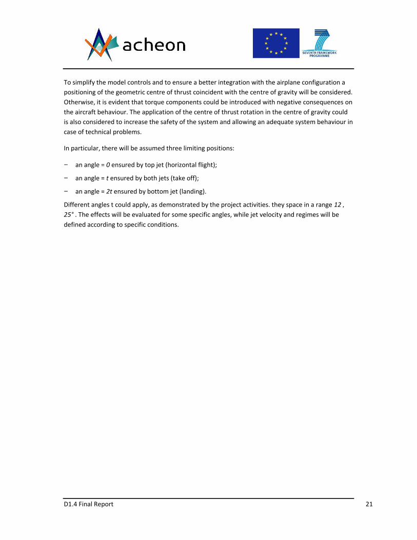
To simplify the model controls and to ensure a better integration with the airplane configuration apositioning of the geometric centre of thrust coincident with the centre of gravity will be considered.Otherwise, it is evident that torque components could be introduced with negative consequences onthe aircraft behaviour. The application of the centre of thrust rotation in the centre of gravity couldis also considered to increase the safety of the system and allowing an adequate system behaviour incase of technical problems.
In particular, there will be assumed three limiting positions:
an angle = 0 ensured by top jet (horizontal flight);
an angle = t ensured by both jets (take off);
an angle = 2t ensured by bottom jet (landing).
Different angles t could apply, as demonstrated by the project activities. they space in a range 12 25° . The effects will be evaluated for some specific angles, while jet velocity and regimes will bedefined according to specific conditions.

D1.4 Final Report 22
Figure 15 - Cessna 402 during takeoff
Figure 16 - Cessna 402 modified for installing acheon.
Energetic and environmental evaluations will be also performed.
To describe the results a specific mission will be considered. The typical mission profile is definedaccording to the FAR standards for commercial vehicles.
In some operations, different operative methods will be taken into account and will be compared.The analysis will also consider FAR standards to verify the suitability of the system for futureapplication into aviation. Further considerations will regard the possible modifications, which could

D1.4 Final Report 23
be necessary to the FAR to allow ACHEON integration. ACHEON will be also preliminarily evaluatedagainst EC Reg. No. 216/2008, identifying future certification needs for flying in Europe. A typicalmission profile is illustrated in Fig. 14.
The results will be compared to the effective performances of Cessna 402 analyzing improved oneand reduced ones. Energy and performance related considerations would be performed focusing onthe specific effects of the all-electric ACHEON propulsion system.
Further consideration will regard the necessity of further improvements, which could be necessaryfor implementing in ACHEON. It is assumed to use the same aerodynamic configuration, which isused for traditional version and equal thrust condition.
The main parameters of the aircraft have been preliminarily calculated. The propulsion model isshown in Fig. 17 The lift and drag data are calculated and reported in Table 5 and the engine data inAnnex 1, will be used as models of the aircraft and engine.
Figure 17 - Preferential use of different configurations during different flight operations
A concrete/asphalt runoff is supposed with friction coefficient 0.02 for takeoff and landingoperations.
D1.4 Final Report 24
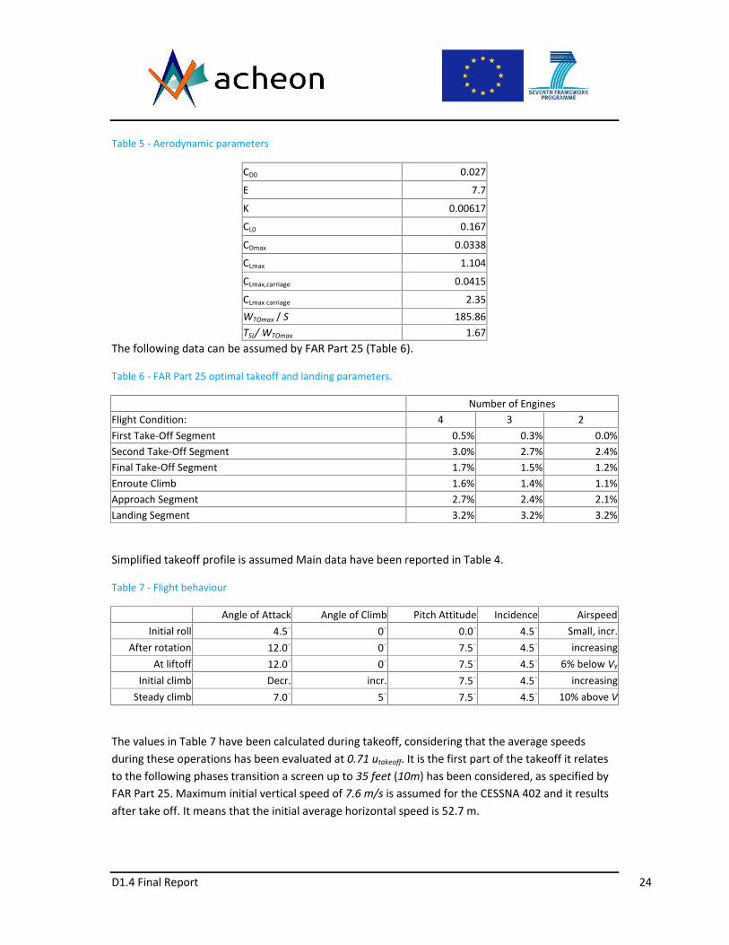
Table 5 - Aerodynamic parameters
CD0 0.027
E 7.7
K 0.00617
CL0 0.167
CDmax 0.0338
CLmax 1.104
CLmax,carriage 0.0415
CLmax carriage 2.35WTOmax / S 185.86TSL/ WTOmax 1.67
The following data can be assumed by FAR Part 25 (Table 6).
Table 6 - FAR Part 25 optimal takeoff and landing parameters.
Number of EnginesFlight Condition: 4 3 2First Take-Off Segment 0.5% 0.3% 0.0%Second Take-Off Segment 3.0% 2.7% 2.4%Final Take-Off Segment 1.7% 1.5% 1.2%Enroute Climb 1.6% 1.4% 1.1%Approach Segment 2.7% 2.4% 2.1%Landing Segment 3.2% 3.2% 3.2%
Simplified takeoff profile is assumed Main data have been reported in Table 4.
Table 7 - Flight behaviour
Angle of Attack Angle of Climb Pitch Attitude Incidence AirspeedInitial roll 4.5∘ 0∘ 0.0∘ 4.5∘ Small, incr.
After rotation 12.0∘ 0∘ 7.5∘ 4.5∘ increasingAt liftoff 12.0∘ 0∘ 7.5∘ 4.5∘ 6% below VY
Initial climb Decr. incr. 7.5∘ 4.5∘ increasingSteady climb 7.0∘ 5∘ 7.5∘ 4.5∘ 10% above V
The values in Table 7 have been calculated during takeoff, considering that the average speedsduring these operations has been evaluated at 0.71 utakeoff. It is the first part of the takeoff it relatesto the following phases transition a screen up to 35 feet (10m) has been considered, as specified byFAR Part 25. Maximum initial vertical speed of 7.6 m/s is assumed for the CESSNA 402 and it resultsafter take off. It means that the initial average horizontal speed is 52.7 m.

D1.4 Final Report 25
Table 8 - Take off parameters
Propellers ACHEONAngle of deflection 15° 10° 5° 0°
Direction of Tx Ty Tx Ty Tx Ty Tx KgThrust 5185.2 5009 1342 5106 900.4 5166 451.9 5185 kW
Max Power 280 280 m/sustall 46.3 26.3 32.9 39.5 46.3 m/s
ustall,carriage, down 31.74 18 22.6 27.1 31.7 KgTake off mass 3105 3105 m/sLift Off Speed 50.93 28.93 36.19 43.45 50.93 m/s
Take off Speed 55.56 31.56 39.48 47.4 55.56 mLiftoff Length 641.5 206.8 323.4 468.4 690 m
Takeoff Length (calculated) 690 222.4 347.8 503.8 690 mTake off length declared 670 m/s
Lift Off Time 16.5 9.48 11.9 14.32 16.5 STake Off Time 17.74 10.2 12.8 15.4 17.74 kJEnergy needs 132012 27468 31068 34668 44280 kJEnergy saving 0 104544 100944 97344 87732 -Energy saving 0 79.19% 76.47% 73.74% 66.46%
Energy needs for take off includes also taxi time wait ant run, according to FAR Part 25. Ten minutesoperations has been estimated. .
Advantages in terms of energy saving are evident at each angle of the takeoff length. It can beverified that if it has been assumed a well defined load factor during operations that could notexceed 1, to ensure an adequate comfort of the passengers,
n=L/W,
which becomes for ACHEON propelled airplanes
n = (L + T sin t ) / W 1,
that constitutes a precise limit to aerodynamic loading in function of the thrust.
L W - T sin t (45).
It shows clearly that the flight asset can be ensured in two ways:
1. by changing lift maintaining directional thrust;
2. by changing thrust direction maintaining aerodynamic lift.
The other evident result is that the same take off performance could be also obtained with a much-reduced aerodynamic lift and then a lower drag.

D1.4 Final Report 26
It is assumed that the plane at the end of takeoff segments up to 10,000 ft (3048 m) reaches thecruise speed (109 m/s).
After the transition phase it is expected a slow transition from the dual jet configuration to allow thejet to adhere to the upper surface, as shown in figure 19, but also a climb with inclined Thrust can beperformed. An angle of attach of 7* has been considered.
The difference in terms of accelerations between the two solutions is evident by subtracting thesystem of equations (13) and (15).
0sin)sin(sincossinsincos
0cos)cos(cossinsincoscos
,
,
cTtcTcTctTctTaam
cTtcTcTctTctTaam
yty
xtx
It is clear the difference of accelerations along x-axis is reduced, while the one along y-axis isincreased.
Average speed during climb can be evaluated in different configurations:
An average climb rate of 6.7 m/s has been assumed. About 40 kWh (144000 kJ) are necessary in allthe configurations. Expected energy consumption is about 140 kWh (504000 kJ) for traditionallypropelled aircraft and about 53 kWh (191000 kJ) for electric ones.
Horizontal Flight
Flight will is estimated considering the above model and standard atmosphere data at 1000m. anaverage angle of attach of 3° has been assumed, even if a twin engine aircraft in cruise could also flywith horizontal axis. Consumption for 1 hour flight at 1000 m and cruise velocity is expected to be1060 kWh (3816000 kJ) for traditional propulsion and about 360 kWh (1296000 kJ) for electrical oneonly because of increased efficiency of electric propulsion. In the case of horizontal flight electricpropelled airplane there is no mass reduction and this aspect must be considered during landingoperations.
Landing energy needs can be evaluated according to usual twin-engine general aviation aircrafts.Typical angle and airspeed during landing are presented in Table 9.

D1.4 Final Report 27
Table 9- Landing, Airspeeds and Angles
Airspeed(KCAS)
PitchAttitude Incidence Angle of
ClimbAngle of
Attackcruise (clean) 100 120 0.0° 4.5° 0.0° 4.5°
level VY (clean) 70 4.0° 4.5° 0.0° 8.5°level (flaps) 70 0.0° 8.5° 0.0° 8.5°
slower (flaps) 65 2.0° 8.5° 0.0° 10.5°descent (flaps) 65 -2.0° 8.5° -4.0° -6.0° 10.5°
flare (flaps) decr. incr. 8.5° incr. incr.stall (flaps) 46.3 12.0° 8.5° 0.0° 20.5°
Landing modes have been presented in Fig 20 assuming a traditional 3° glideslope. Figure 21 showsinstead the complete landing manoeuvre considered. It is clear that gliding takeoff requires lowenergy needs. A 3° degree glideslope for a traditional Cessna 402 will require a landing space, whichcan be calculated and against the value of 757 m (declared by the producer). Calculations give aworst result of about 763 m, which is acceptable because of the necessary approximations incalculations.
Data between the descent phase and landing using ACHEON can be assumed adopting a differentprofile (Table 10).
Table 10 - Landing, Airspeeds and Angles with ACHEON
Airspeed(KCAS)
PitchAttitude Incidence Angle of
ClimbAngle of
Attackcruise (clean) 100 120 0.0° 4.5° 0.0° 4.5°
level VY (clean) 70 4.0° 4.5° 0.0° 8.5°level (flaps) 70 0.0° 8.5° 0.0° 8.5°
slower (flaps) 4065 2.0° 8.5° 0.0° 10.5°descent (flaps) 4065 -2.0° 8.5° -3.0°-12.0° 10.5°
flare (flaps) decr. Incr. 8.5° Incr. incr.0° 0° 46.3 12.0° 8.5° 0.0° 20.5°5° 10° 39.5 12.0° 8.5° 0.0° 20.5°
10° 20° 32.9 12.0° 8.5° 0.0° 20.5°
stall (flaps)for different angles of
thrust(half power angle) 15° 30° 26.3 12.0° 8.5° 0.0° 20.5°
Different profiles of climbing has been considered for ACHEON propelled aircraft. they can beensured by hybrid combination of vertical component of the thrust, when adhering to the lowersurface and aerodynamic lift. In this case the thrust in vertical direction could be almost equal to theone during takeoff, while the horizontal one is much reduced. Angle of attack is considered the sameas above. Considering different stall speeds ad maximum deceleration about 3 m/s both spaces andtimes for landing operations have been calculated. Results are presented in Table 8.

D1.4 Final Report 28
Table 11 - Landing performances in different configurations
Inclination of the nozzle 15 10 5 0°Nozzle angle 15 10 5 0° deg
Direction of thrust 30 20 10 0 degTx Ty Tx Ty Tx Ty Tx
Thrust 2245.17 1296.25 2436.15 886.69 2553.11 450.18 2592.50 kgMax Power 140 kW
ustall 26.3 32.9 39.5 46.3 m/sustall,carriage, down 18 22.6 27.1 31.7 ùLanding mass 3105 kgGliding Speed 32.875 41.125 49.375 55.56 m/s
Touch down Speed 28.93 36.19 43.45 50.93 m/sLanding Space (calculated) 431.71 540.04 648.38 760 m
Average landing acceleration 2.03 2.03 2.03 2.03 m/s2Landing Time 14.25 20.26 24.32 2.00 s
Ground roll Time 14.25 17.83 21.40 25.09 sBraking Energy 2598.71 4066.67 5861.94 8053.95 kJBraking energy 1559.23 2440.00 3517.16 4832.37 kJ
Braking Energy saving 3273.14 2392.37 1315.21 0 kJEnergy saving 40.64% 29.70% 16.33% 0 %
It is now evident that ACHEON can also perform better performances in case of landing.
The ACHEON propulsion system can be improved by optimizing the inlet by an effectiveimprovement of the inlet section, as verified by Trancossi and Madonia. By optimizing the air intakedesign it can be possible to increase the propulsive efficiency especially at high altitude. But thislevel of optimization it is not performed at this level because it requires a more effective designactivity.
This analysis focus on the energy analysis of the electrical ACHEON propelled Cessna 402 against themodel on the market. This analysis produces some interesting results.
In particular, the energy comparison are presented in Table 12. An emergency reserve higher than15% is assumed to ensure some minutes flight for the electric ACHEON Propelled aircraft then thetime for flight at cruise condition could not exceed 20 min for electric ACHEON propelled plane.

D1.4 Final Report 29
Table 12 - Energy performances
ConfigurationCessna 402 Cessna 402 ACEON
Flight Condition: traditional 15° 10° 5° 0°Take-Off 132012 27468 31068 34668 44280 kJ
Second Take-Off Segment 504000 139100 kJEnroute (30min) 1908000 636000 kJ
Approach Segment 267120 53000 kJLanding Segment 396036 8240 9320 10400 13284 kJ
Energy consumption 3207168 863808 868488 873168 885664 kJMax on board energy 0 1229580 kJ
Reserve -3207168 365772 361092 356412 343916 kJ
It can be verified that the original configuration is not adequately performing in terms of autonomyand energy storage. A better energy efficiency and cruise performance of the ACHEON propelledaircraft can be obtained by decreasing cruise speed about 324 km/h (90 m/s). data in this caseincrease to 40 min cruise speed.
Assuming average European electric production efficiency [49], which has been estimated about50% in 2010, the effective energy demand will be about double than declared consumptions, butmuch lower than the one for the conventional engine.
More improved performances can be ensured by equipping the plane by an electric lightweightcogeneration system coupled by heat recovery system. Assuming a Rolls Royce-Allison Model 250C20R turboprop [49] with a max nominal power of about 190 kW and continuous power about 170kW (602.5 MJ) is considered. It has a weight of 62 kg dry (0.32 kg/kW). Considering all the necessaryaccessories a weight about 1.2 kg/kW can be conservatively assumed, including the heat recoverysystem. Assuming the hypothesis of recovering heat from the turboprop and recovering it by heatingthe fluid flow, preliminarily conceived by Trancossi, patented by Dumas et al and studied byTrancossi et al. Using the same calculation methodology used by Trancossi et al., thermal emissioncan be calculated by considering consumption about 0.48 kg/kWh and a conservative global thermalexchange efficiency about 0.4. The amount of recovered heat per hour is then 338.65 kWh (1220MJ).
It means an increase in terms of thrust about 30% that means a reduction of required electric powerabout 54 kW.
This new condition allows ensuring flight with a partial system redefinition and general improve,with overall energy efficiency about three times the one of the traditional airplane.
In this case, it can be considered the following configuration 250 kg of fuel, 250 kg cogenerationsystem and 1050 kg batteries.
This configuration could allow flight endurance about 6 hours with a sufficient reserve,

D1.4 Final Report 30
This result is also interesting because the heat exchanger produces some losses but can be also usedas a stator for straightening the jet as demonstrated by Shyam and Trancossi, which increases theadhesion, but also a positive thermal difference is a benefit because of an increased adhesioncapability as demonstrated by Subhash in his thermal analysis.
The resulting configurations is summarized in Table 10.
Table 13 - Modified Cessna 402 Cogeneration Architecture for high energy performances
Empty weight Lb 4,069Useful load Kg 662
Max takeoff weight Kg 3107Batteries (Boston Power Swing® 5300 Rechargeable Lithium-ion Cell)
Kg 1050Wh/kg 207
Ah 4,420Fuel
Max on board fuel
Kg 640Propulsion
Cogen Rolls Royce Model 250Power kW 250
Mass Kg 250Motor Four Plettemberg Nova 150 mounted in two ACHEON NozzlePower kW 150
Mass Kg 11.5Performances
Max speed m/s 118.9Max cruising speed m/s 109.4
Stall Speed m/s 46.3Stall Speed Carriage m/s 25.1Initial rate of climb m/s 7.366
Service ceiling M 8200Long range cruising speed m/s 84.4
Range with reserves ateconomical cruising speed
km 2000
The operated reduction of payload, which has been assumed in previous all electric architecture ismaintained.
It has been clearly demonstrated the benefits of the ACHEON nozzle applied to the propulsion of acommuter class transport twin-engine aircraft. The choice has been focused on the Cessna 402aircraft because its geometric conformation, which could easily allow a positioning of the ACHEONnozzle with centre of thrust almost coincident with centre of mass. The paper produces the basiccontrol equations of an aircraft with this singularity showing the benefits of variable direction thrustapplied in this position.

D1.4 Final Report 31
For simplicity three only positions has been considered, because they seems the state that can beeasily produced at this level of research activity. They are full thrust (two fans on) with an angle t ofinclination (with t comprised between 0° and 15 °. A nozzle with opening equal to t so that twoextreme positions could be stabile:
0° for horizontal flight, with higher jet near 100% ant the other below 50%.
2t for takeoff operations to sustain the airplane during operations with lower jet about 100%
and lower below 50%.
Figure 18 - ACHEON configuration on a longitudinal plane section and main directions of Jets
Kinematic and dynamic main parameters has been estimated during critical operations such as takeoff and landing verifying the benefits produced by the ACHEON nozzle in different flight condition. Itappears fundamental, even if not directly presented in the paper, the importance of DBD to ensurean effective governable transition between the positions to avoid both too fast modifications of theairplane behaviour with potential stability problems and the actual considered capacity of producingthrust in three well-defined directions.
In particular, further application could benefit of the preliminary definition of a possible single jetarchitecture, which aims to reduce the problems derived from high frontal section required by thedual jet configuration.
A preliminary airplane configuration equipped by high performance batteries is presented.
Energetic evaluations has been performed demonstrating clearly the advantages of the proposed allelectric system because of much higher energy conversion efficiency and because of the possibility,which has been presented to define a cogeneration airplane architecture equipped by a Rolls-RoyceModel 250 turboprop based cogeneration unit. The large disposability in terms of heat to bedispersed could ensure the possibility of producing a more effective propulsion effect by using themto heat the jets produced by the ducted fans.
The clear advantages of the cogeneration based solution against the battery only one is evidentdemonstrating the possibility of an effective applicability of ACHEON all electric propulsion in thefuture, with a cogeneration based propulsion architecture.

D1.4 Final Report 32
In conclusion, demonstrates the benefits of ACHEON based architecture to civil aircrafts ensuringadequate performances. Even if it is not still sufficient for future ACHEON equipped aircrafts it is apreliminary basis for continuing the studies on ACHEON thought a novel class of all electrical highperformance aircrafts, which could not been thought before this revolutionary project.
UAS IMPLEMENTATION
The implementation on a UAS architecture, based on the Nimbus original configuration has alosoallowed producing an effective result of a UAS that can takeoff and land in about 12 m with a massof 4.5 kg and cruise as low as 8-12 m/s (but even lower) opening novel frontiers for low speed UAS.
This UAS concept has been named MURALS (acronym of Multifunctional Unmanned ReconnaissanceAircraft for Low-speed and STOL operation) which has been studied by joint activity of the memberof the project.
This aerial vehicle concept envisages and develops a previous concept of an innovative single seat jetdeveloped by Aeritalia and Alfredo Capuani, making it suitable for ACHEON based propulsion. In afirst embodiment, the aircraft according to the invention has a conventional form with a singlefuselage and its primary objective is to minimize the variation of the pitching moment allowing lowspeed operations.

D1.4 Final Report 33
Figure 19. ACHEON integration scheme in Light UAS novel prototype (Original Design)
Figure 20. ACHEON integration and lateral view of the previous three analysed cases (15° take-off, 45° landing,0-5° cruise condition)
Figure 21. A section view of the airplane concept.
Main objective of the airplane is to allow control by mobile surfaces in the front canard and in thelarge wing. This plane has been specifically designed to flight at low velocities with a very high angleof attach without loosing in terms of agility.
The resulting airplane concept is specifically designed for road monitoring, and police support and ischaracterized. The results define an optimal sizing of the aircraft together with an effectiveperformance analysis, which allows identifying the strong points and the potential problems of theproject. An effective energy analysis has been performed also.

D1.4 Final Report 34
Figure 22 - Lift and Drag analysis
Figure 23. Thrust directions and aircraft angles
Figure 24. Airplane configuration in steady flight
Figure 25. Forces on airplane during descent
Table 14. Aircraft data
External volume m3 0.0250.03
Main front area m2 0.07-0.85
Main aircraft planform area m2 0.4-0.5
Main rear wing planform area m2

D1.4 Final Report 35
Total mass (kg) Kg 5.56.5
Maximum Load factor - 4-5
Wing span (m) M 0.9-1.1
Length M 0.951.1
Max takeoff thrust kg 3.1
Max takeoff Power W 2400
CL,max - -2.0 2.5
CL,cruise - 1 1.5
deg 7 9
deg 15
According to the above defined models and components it is possible to start an effective evaluationof the performances. The main coefficients have been defined by Capuani and Sunol and Vucinic:CDmax = 0.1 (at takeoff), CDmin 0.035, CLmax=3.0, CLmin=1, AR=5, L/D = 10, and friction c0efficientwith ground 0.05.
Table 15. Main Components
Unitarymass Number
Totalmass
Component G - gPropellers 37 4 148Motors 72 3 216Speed control 26 4 104Servo 85 4 340Receiver 50 1 50Battery 786.2 2 1572.4Cabling and accessories 200 1 200
Total mass 2630.4
Takeoff performances are acceptable. Assuming an angle of attack of 7.5° and an angle of thefuselage and thrust 7.5°, making the hypothesis of max thrust, Vstall is about 9 m/s and assuming aspeed Vtakeoff = 10.65, a complete takeoff length about 12 m, and a run of less than anacceleration of 3 m/s.

D1.4 Final Report 36
Figure 26. Aircraft preliminary dimensions
Climbing it can be effectuated a climb with an angle of 20° about and a speed about 14 m/s withangle of attack 7.5. Thrust is oriented upward wit an angle of 15°. It requires 2 ducted fan units withthrust oriented up and an angle of attach about 7.5°.
Cruise can be ensured also at low speed about 1012 m/s with opportune lift. Assuming a cruisespeed of 25 m /s at min drag (about 1), it can be possible to estimate energy consumption.
Landing space results less than 12 m.
Assuming a reserve about 30%, it is possible to estimate more than 1-hour flight with selectedbatteries.
A precise design methodology for an innovative airplane based on the ACHEON propulsion systemand based on the innovative MURALS configuration has been defined. .
Starting from methodological results an effective design activity will be produced taking into accountthe preliminary statements. After considering results from conceptual design, some importantconclusions were drawn.
The proposed airplane architecture is very interesting for low speed operations and short take offand landing. The results show clearly that the designed aircraft meets the predefined objectives.
The weight of the overall structure of about 3 kg is acceptable however. It can be reduced byimproving the design. This reduction will produce a further increase of the performances.

D1.4 Final Report 37
The airplane could be also improved considering a carbon fibre structure instead of the consideredfoam, both in terms of structural loads and in terms of better performances and accuracy ofcomponents, with a consequent reduction of weights.
The best wing loading can be achieved by carefully consider the aspect ratio of the main wing. Abetter wing loading can be achieved by carefully designing the fuselage profile.
Jet deflection studies performed in ACHEON project can affect dramatically novel concepts ofaircraft vehicle design (both manned and unmanned) with enhanced manoeuvrability withoutmoving parts resulting in energy savings and maintenance advantages.
Radical new concept of aircrafts can be joined to jet vectoring study to improve comfort,manoeuvrability and energy efficiency. Flight control without mobile parts and tails for light UAVsegment cannot be reached without a full comprehension of directional control of propulsive jets.
From a market point of view, the ACHEON project applied to the UAS sector can make availablenovel platforms in terms of size, architecture and control system. This feasibility study of propulsivethrust vectoring can be integrated in the pre-design phase of new UAV concepts to enhancemaneuverability and open up radical new product families.
With some further improvements, it can safely take off and land over a 40 ft container making itideal for escort missions, civil protection and police fast intervention on roads, but also for manymilitary missions.
REFERENCES1. Baffigi F., Dumas A., Giuliani I., Madonia M., and Trancossi M., (2014) "Ugello capace di deviare in modo
dinamico e controllabile un getto sintetico senza parti meccaniche in movimento e relativo sistema dicontrollo", Patent IT 0001406404, Deposito RE2011A000049, Filling date July 01, 2011, Publication dateSeptember 30, 2011, approved on February 21, 2014.
2. Baffigi F., Dumas A., Giuliani I., Madonia M., and Trancossi M., (2014), "Nozzle capable of deviating asynthetic jet in a dynamic and controllable manner with no moving mechanical parts and a control systemthereof", PTC Patent WO2013005132 A1, Publication date Jan 10, 2013, Filing date Jun 25, 2012, Prioritydate Jul 1, 2011, Published also as EP2726213A1, US20140191059
3. Cattafesta, L. N., and Sheplak, M., (2011) "Actuators for Active Flow Control" Volume 43, Issue 1: pp. 247-272
4. Páscoa, J.C., Brójo F. M. P., and Monteiro J. M. M., "Numerical Simulation of Magneto-plasma Thrustersfor Aerospace Propulsion Using and MHD Formulation", Paper O-7.2, Proc. 14th International Conferenceon Emerging Nuclear Energy Systems, Instituto Tecnológico e Nuclear, 6 pgs, 2009.
5. Trancossi, M., “An Overview Of Scientific And Technical Literature On Coanda Effect Applied To Nozzles”,SAE Technical Papers N. 2011-01-2591, 2011.
6. Drăgan V.: A New Mathematical Model for Coandă Effect Velocity Approximation. INCAS Bulletin, vol.4,pp.85–92, (2012).
7. Trancossi, M., Dumas, A., “Coanda Syntetic Jet Deflection Apparatus And Control”, SAE Technical Papers N.2011-01-2590, 2011.

D1.4 Final Report 38
8. Trancossi, M., Dumas, A., “ACHEON: Aerial Coanda High Efficiency Orienting-Jet Nozzle ”, Sae TechnicalPapers N. 2011-01-2737, 2011.
9. ACHEON - Aerial Coanda High Efficiency Orienting-jet Nozzle, European Commission, Project reference:309041, Funded under: FP7-TRANSPORT, 2011. http://cordis.europa.eu/project/rcn/103805_en.html.
10. Dumas, A., Pascoa, J., Trancossi, M., Tacchini, A., Ilieva, G., and Madonia, M. (2012), "Acheon project: Anovel vectoring jet concept" , Proc. ASME. 45172; Volume 1: Advances in Aerospace Technology: 499-508, IMECE2012-87638.
11. Trancossi, M., Dumas, A., and Vucinic, D., "Mathematical Modeling of Coanda Effect," SAE Technical Paper2013-01-2195, 2013, doi:10.4271/2013-01-2195.
12. Subhash, M. and Dumas, A., "Computational Study of Coanda Adhesion Over Curved Surface," SAE Int. J.Aerosp. 6(1):260-272, 2013, doi:10.4271/2013-01-2302.
13. Dumas, A., Subhash, M., Trancossi, M., and Marques, J.P., "The influence of surface temperature onCoanda effect", Energy Procedia Vol. 45, pp. 626-634, 2014.
14. Das, S.S., Abdollahzadeh, M., Pascoa, J. C., Dumas, A., and Trancossi, M., (2014) "Numerical modeling ofCoanda effect in a novel propulsive system", Int. Jnl. of Multiphysics, Volume 8 • Number 2, pp. 181-201.
15. Trancossi M, Subhash M., Angeli D. Mathematical modelling of a two streams Coanda effect nozzle. ASMEInt. Mech. Engg. Conf. and Exhibition, paper no. IMECE2013-63459; 2013.
16. Trancossi, M., Dumas, A., Das, S. S., and Páscoa, J. C., (2014) "Design Methods of Coanda nozzle with twostreams", INCAS Bulletin, Volume 6 (1), Pages 83-95, ISSN 2066-8201, doi: 10.13111/2066-8201.2014.6.1.8
17. Dragan V., "Reynolds number calculation and applications for curved wall jets", INCAS Bulletin, Volume 6,Issue 3, pp. 35 – 41, 2014.
18. Pascoa, J. C., Dumas, A., Trancossi, M., Stewart, P., and Vucinic, D., "A review of thrust-vectoring insupport of a V/STOL non-moving mechanical propulsion system" Cent. Eur. J. Eng., 3(3), pp. 374-388,2013.
19. Páscoa, J.C., Brójo F. M. P., and Monteiro J. M. M., "Numerical Simulation of Magneto-plasma Thrustersfor Aerospace Propulsion Using and MHD Formulation", Paper O-7.2, Proc. 14th International Conferenceon Emerging Nuclear Energy Systems, Instituto Tecnológico e Nuclear, 6 pgs, (2009).
20. Abdollahzadeh M., and Pascoa J., Modified Split-Potential Model for Modeling the Effect of DBD PlasmaActuators in High Altitude Flow, Control Current Applied Physics, (2014).
21. Abdollahzadeh, M., Páscoa J.C., and Oliveira P.J., "Two-dimensional numerical modeling of interaction ofmicro-shock wave generated by nanosecond plasma actuators and transonic flow", Journal ofComputational and Applied Mathematics, Volume 270, pp. 401-416, 2014.