graphical user interface of an interactive system for wireless
TRANSCRIPT

Graphical User Interface of an InteractiveSystem for Wireless Sensor Networks:
Design and Development
HWAKYUNG KIM
Masters’ Degree ProjectStockholm, Sweden October 2008
XR-EE-RT 2008:022

Abstract Wireless sensor networks (WSNs) are utilized for ubiquitous and pervasive computing to detect contextual information as well as represent a new monitoring and control ability for applications in industries, transportation and health care. A user is able to gain the effective use of captured context by the sensor network. The WSN software application is an important tool to visualize the information for the different applications. This research provides how to design WSN software application for visual user interface and how to develop WSN system in order to use it in practice. We apply a graphical user interface (GUI) to enhance the intuitiveness of the interactive system. Activity Theory (AT) helps WSN software application make user-centered design. WSN GUI application is implemented with Java Swing on TinyOS, an operating system for WSNs. Furthermore, Java Web Start and the web database support WSN system to provide the GUI software applications via the internet.
I

Table of contents Abstract . . . . . . . . . . . . . . . . . . . . . . . . . . . . . . . . . . . . . . . . . . . . . . I
CHAPTER 1. Introduction
1.1 Description of the Research Area . . . . . . . . . . . . . . . . . . . . 1 1.2 Research Purpose and Goal . . . . . . . . . . . . . . . . . . . . . . . . . 2 1.3 Contribution . . . . . . . . . . . . . . . . . . . . . . . . . . . . . . . . . . . . . 3 1.4 Outline . . . . . . . . . . . . . . . . . . . . . . . . . . . . . . . . . . . . . . . . . 4
CHAPTER 2. Extended Background
2.1 Wireless Sensor Networks. . . . . . . . . . . . . . . . . . . . . . . . . . 5 2.1.1 WSNs Applications. . . . . . . . . . . . . . . . . . . . . . . . . . 8 2.1.2 Wireless Sensor Node Hardware. . . . . . . . . . . . . . . . 9 2.1.3 Protocol Stack. . . . . . . . . . . . . . . . . . . . . . . . . . . . . . 10 2.1.4 Routing Techniques. . . . . . . . . . . . . . . . . . . . . . . . . . 12 2.1.5 Sensor Network Database. . . . . . . . . . . . . . . . . . . . . 14 2.2 Design Process of an Interactive System. . . . . . . . . . . . . . . 16 2.3 Activity Theory. . . . . . . . . . . . . . . . . . . . . . . . . . . . . . . . . . . 19
CHAPTER 3. Design of WSN System
3.1 Personas . . . . . . . . . . . . . . . .. . . . . . . . . . . . . . . . . . . . . . . . 21 3.2 Applying Activity Theory . . . . . . . . . . . . . . . . . . . . . . . . . . 23 3.3 Sketching and Prototyping . . . . .. . . . . . . . . . . . . . . . . . . . . 28
II

CHAPTER 4. Implementation of WSN System 4.1 Hardware Technologies . . . . . . . . . . . . . . . . . . . . . . . . . . . . 33 4.2 Software Technologies . . . . . . . . . . . . . . . . . . . . . . . . . . . . . 35 4.2.1 Tiny OS . . . . . . . . . . . . . . . . . . . . . . . . . . . . . . . . . . 35 4.2.2 Protocol Design . . . . . . . . . . . . . . . . . . . . . . . . . . . . 37 4.2.3 Java Swing . . . . . . . . . . . . . . . . . . . . . . . . . . . . . . . . 37 4.2.4 Java Web Start . . . . . . . . . . . . . . . . . . . . . . . . . . . . . 39 4.3 Implementation of WSN System . . . . . . . . . . . . . . . . . . . . . 42 4.3.1 Set up for WSN System . . . . . . . . . . . . . . . . . . . . . . 43 4.3.2 Implementation of functions and screens . . . . . . . . . 44 4.3.3 Implementation on the Web . . . . . . . . . . . . . . . . . . . 58
CHAPTER 5. CONCLUSIONS
5.1 Conclusion of the Work . . . . . . . . . . . . . . . . . . . . . . . . . . . 66 5.2 Future Work . . . . .. . . . . . . . . . . . . . . . . . . . . . . . . . . . . . . . 67
References . . . . . . . . . . . . . . . . . . . . . . . . . . . . . . . . . . . . . . . . . . . . 68 Appendix . . . . .. . . . . . . . . . . . . . . . . . . . . . . . . . . . . . . . . . . . . . . . . 73
III

List of Codes Code 1. createAndShowWPanel() method . . . . . . . . . . . . . . . . . . . . 48 Code 2. MenuTree shape and mnutreeView() method . . . . . . . . . . . 49 Code 3. The panels of the main (mapPanel), user (UmapPanel) and administrator (AmapPanel) & MapPanel Class . . . . . . . . . . . . . . . . . 51 Code 4. Chart shape and ChartPanel class . . . . . . . . . . . . . . . . . . . . . 53 Code 5. Slider shape and RequestPanel class . . . . . . . . . . . . . . . . . . 54 Code 6. Run() method of O-WSN GUI . . . . . . . . . . . . . . . . . . . . . . . 56 Code 7. messageReceived() method of O-WSN GUI . . . . . . . . . . . . 56 Code 8. waitMutex() . . . . . . . . . . . . . . . . . . . . . . . . . . . . . . . . . . . . . 58 Code 9. DBconnection() method . . . . . . . . . . . . . . . . . . . . . . . . . . . . 60 Code 10. Inserting data into DB & WsnDB class for I-WSN GUI . . 61 Code 11. Showing and Selecting data from DB for S-WSN GUI . . . 63
IV

List of Figures Figure 1. WSN Architecture . . . . . . . . . . . . . . . . . . . . . . . . . . . . . . . 5 Figure 2. Hardware elements of the wireless sensor node . . . . . . . . . 9 Figure 3. Protocol stack of WSNs . . . . . . . . . . . . . . . . . . . . . . . . . . . 10 Figure 4. An Extended model of Activity Theory . . . . . . . . . . . . . . . 20 Figure 5. Hierarchical structure of activities . . . . . . . . . . . . . . . . . . . 24 Figure 6. Activity system model in Activity level . . . . . . . . . . . . . . . 25 Figure 7. Activity system model in Action level for Monitoring . . . 26 Figure 8. Activity system model in Action level for Colleting Context Info . . . . . . . . . . . . . . . . . . . . . . . . . . . . . . . . . . . . . . . . . . . .
27
Figure 9. Activity system model in Action level for Controlling devices . . . . . . . . . . . . . . . . . . . . . . . . . . . . . . . . . . . . . . . . . . . . . . . .
27
Figure 10. Sketching . . . . . . . . . . . . . . . . . . . . . . . . . . . . . . . . . . . . . 28 Figure 11. The comparison of Prototyping versions . . . . . . . . . . . . . 39 Figure 12. Menu buttons VS Hierarchical folder menu . . . . . . . . . . . 30 Figure 13. Prototyping . . . . . . . . . . . . . . . . . . . . . . . . . . . . . . . . . . . . 32 Figure 14. The process of Java Web Start . . . . . . . . . . . . . . . . . . . . . 40 Figure 15. Setup for WSN system . . . . . . . . . . . . . . . . . . . . . . . . . . . 43 Figure 16. Structure of WSN GUI . . . . . . . . . . . . . . . . . . . . . . . . . . . 45 Figure 17. The main screens of WSN GUI . . . . . . . . . . . . . . . . . . . . 46 Figure 18. Class Diagram of Panels . . . . . . . . . . . . . . . . . . . . . . . . . . 47 Figure 19. Class Diagram focused on Scout . . . . . . . . . . . . . . . . . . . 55 Figure 20. Structure of SyncMsg . . . . . . . . . . . . . . . . . . . . . . . . . . . . 58 Figure 21. Structure of I-WSN GUI . . . . . . . . . . . . . . . . . . . . . . . . . . 59
V

Figure 22. Class Diagram of I-WSN GUI . . . . . . . . . . . . . . . . . . . . . 60 Figure 23. Structure of S-WSN GUI . . . . . . . . . . . . . . . . . . . . . . . . . 62 Figure 24. Class Diagram of S-WSN GUI . . . . . . . . . . . . . . . . . . . . . 63 Figure 25. Launching software application on the web browser . . . . 65
VI

Chapter 1
Introduction
1.1 Description of the Research Area Nowadays, the context is an important and essential element in many research fields such as ubiquitous computing, pervasive computing and context-aware computing. Context is any information that can be used to characterize the situation of an entity. An entity is a person, a place or an object that is relevant to the interaction between a user and a software application, including the user and the software application themselves. A system is the context-aware if it uses the context to provide relevant information and/or services to the user, where relevancy depends on the task of a user [1]. Wireless sensor networks (WSNs) are network systems with sensor nodes, by which some contextual information like temperature, sound, and motion can be detected in the physical world, and gateway of sensor nodes. Using WSNs, we can collect the data which users want, acquire the context information to prevent dangerous situations, as well as control other devices with collected data. The wireless communication and digital electronics allow us to develop sensor nodes that are small,
Chapter 1. Introduction 1

inexpensive, low-power and has the communication function in a short distance [15]. They also form self-organizing networks and transfer the information among senor nodes that have computation ability. WSNs can be applied to many real fields because it is easy to connect physical world and digital world. For example, WSN applications are used for building automation, factory automation and monitoring, and structural health monitoring. WSN is used for various ubiquitous and pervasive environments and it represents an emerging technology with a very diverse range of applications [25] [26].
1.2 Research Purpose and Goal The energy consumption and the packet losses are problems that must be addressed in the design of WSNs [3]. In order to collect reliable information, sensor networks should be operative for a long time and minimize network traffic loss. It is a challenging task to check inward network working status and get continuous information from sensors. Therefore, we suggest visual Graphic User Interface (GUI) applications to monitor problems and control network effectively in WSN system that we set up for this research. WSN system is extended by WSN GUI applications, the database and Java Web Start. WSN GUI application shows the status of sensor nodes and constitution of sensor network with data coming from sensor nodes. Many kinds of gathered data are trimmed to display useful and necessary data on the software application screen after the data from each sensor node are delivered to the gateway connecting to the computer. WSN system can be combination of WSN GUI applications, the database and web. One of WSN GUI applications in WSN system inserts data from sensor nodes to the database. All of necessary data are saved in the database and selecting data from the database show up
Chapter 1. Introduction 2

through GUI in any place connecting to an internet. We apply activity theory (AT) and the design process of an interactive system to develop more user-friendly and visual WSN GUI application. The interactive system helps users to well-interact with the machine. AT is shaped through the interactions of the various components of that activity, such as a subject, an object, the tools, the rules, a community, or a division of labor. AT provides a multidimensional approach to interpret the actions by allowing the researcher to view informant data through any components of AT. As a method for interpreting qualitative action data, AT allows a wide set of interpretation of the data that include the relationships between a subject, its community and its rules [27]. In other words, the interpretations of user actions and relationship of components present the concept and characteristic of a software application. They are based on designing an interactive system. AT shows the overall flow diagram and dedicate outline of our implementation. For example, the elements of implementation like Class, method and variables are decided by components and activity model of AT for our implementation. It is the strong motivation to apply AT. The interactive system design process such as personas, brainstorming and bodystorming, sketching, and prototyping, helps that the requests of users are correctly analyzed, user interface (UI) containing common features is assembled, and the design is trimmed by many evaluations to make user-friendly and usable software application.
1.3 Contribution The main contributions of this thesis are two:
How to design WSN GUI application as an interactive system to
Chapter 1. Introduction 3

communicate more efficiently between the system and the human
How to develop WSN system in order to use more widely in the real world.
1.4 Outline
In Chapter 2, we describe general features of WSNs. The interactive system design process and AT are introduced. In Chapter 3, it is shown how to apply AT and interactive system design process for designing WSN system. The implementation aspects are described in Chapter 4. Conclusion and future works are resumed in Chapter 5.
Chapter 1. Introduction 4

Chapter 2
Extended Background
2.1 Wireless Sensor Networks Wireless sensor networks are ad-hoc networks, consisting of spatially distributed devices using sensor nodes to cooperatively monitor physical or environmental conditions at different locations [3].
Figure 1. WSN Architecture
In Figure 1, sensor nodes are usually scattered in a sensor field,
Chapter 2. Extended Background 5
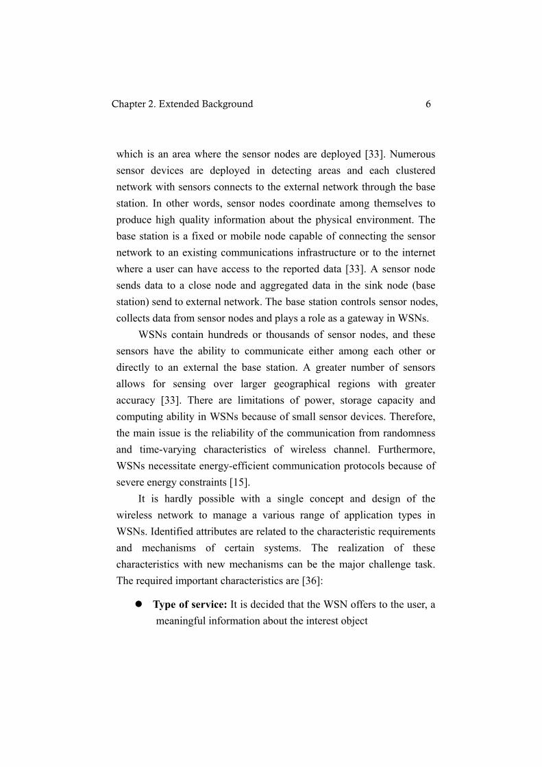
which is an area where the sensor nodes are deployed [33]. Numerous sensor devices are deployed in detecting areas and each clustered network with sensors connects to the external network through the base station. In other words, sensor nodes coordinate among themselves to produce high quality information about the physical environment. The base station is a fixed or mobile node capable of connecting the sensor network to an existing communications infrastructure or to the internet where a user can have access to the reported data [33]. A sensor node sends data to a close node and aggregated data in the sink node (base station) send to external network. The base station controls sensor nodes, collects data from sensor nodes and plays a role as a gateway in WSNs. WSNs contain hundreds or thousands of sensor nodes, and these sensors have the ability to communicate either among each other or directly to an external the base station. A greater number of sensors allows for sensing over larger geographical regions with greater accuracy [33]. There are limitations of power, storage capacity and computing ability in WSNs because of small sensor devices. Therefore, the main issue is the reliability of the communication from randomness and time-varying characteristics of wireless channel. Furthermore, WSNs necessitate energy-efficient communication protocols because of severe energy constraints [15]. It is hardly possible with a single concept and design of the wireless network to manage a various range of application types in WSNs. Identified attributes are related to the characteristic requirements and mechanisms of certain systems. The realization of these characteristics with new mechanisms can be the major challenge task. The required important characteristics are [36]:
Type of service: It is decided that the WSN offers to the user, a meaningful information about the interest object
Chapter 2. Extended Background 6
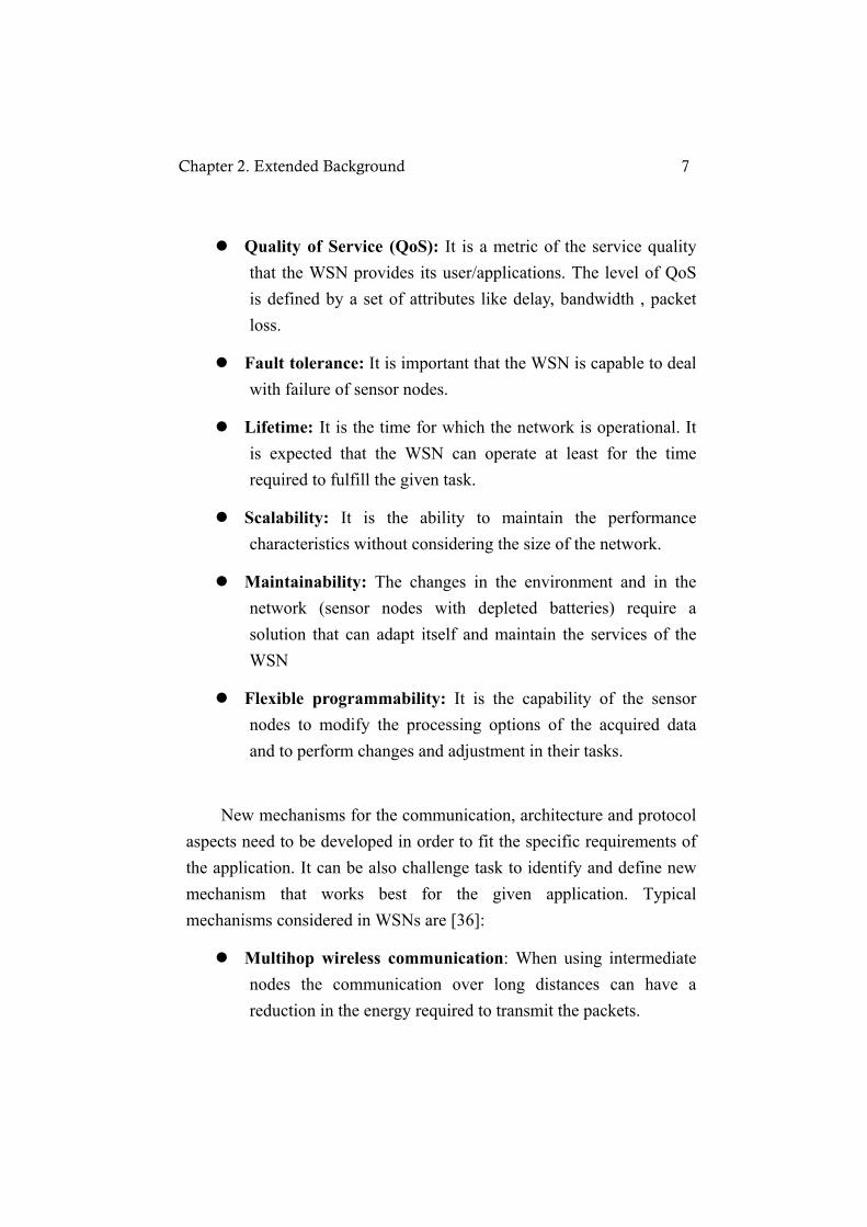
Quality of Service (QoS): It is a metric of the service quality that the WSN provides its user/applications. The level of QoS is defined by a set of attributes like delay, bandwidth , packet loss.
Fault tolerance: It is important that the WSN is capable to deal with failure of sensor nodes.
Lifetime: It is the time for which the network is operational. It is expected that the WSN can operate at least for the time required to fulfill the given task.
Scalability: It is the ability to maintain the performance characteristics without considering the size of the network.
Maintainability: The changes in the environment and in the network (sensor nodes with depleted batteries) require a solution that can adapt itself and maintain the services of the WSN
Flexible programmability: It is the capability of the sensor nodes to modify the processing options of the acquired data and to perform changes and adjustment in their tasks.
New mechanisms for the communication, architecture and protocol aspects need to be developed in order to fit the specific requirements of the application. It can be also challenge task to identify and define new mechanism that works best for the given application. Typical mechanisms considered in WSNs are [36]:
Multihop wireless communication: When using intermediate nodes the communication over long distances can have a reduction in the energy required to transmit the packets.
Chapter 2. Extended Background 7

Energy efficient operation: It is a key mechanism to offer and support long time operation of the network.
Self-configuration: The sensor node should be capable to adapt its operation parameters, to deal with node failure, obstacles and addition of nodes in the network.
Collaboration and in-network processing: in accordance with the application, it is required that a group of sensor nodes interact to detect an event or to make a more complete processing of the information.
Data-centric: In common applications, the sensor nodes are deployed in a redundant way to protect the network against node failures. In a data-centric view, the identity of the particular node that supplies data becomes irrelevant Data-centric paradigm finds use in applications where the task is to be aware of alerts or events as well.
2.1.1 WSN Applications WSNs make the environment able to communicate with sensors attached on necessary places to detect and manage the environment information such as temperature, humidity, and pollutions in the real [2]. The use of pervasive networking technology gives WSNs a new kind of scope that can be applied to a wide range of uses such as monitoring space, monitoring things, and monitoring the interactions of things with each other and encompassing space [30].
Monitoring space: The applications for monitoring space include environmental and habitat monitoring, precision agriculture, indoor climate control, surveillance, treaty
Chapter 2. Extended Background 8

verification, and intelligent alarm.
Monitoring things: The applications for monitoring things include structural monitoring, ecophysiology, condition-based equipment maintenance, medical diagnostics, and urban terrain mapping.
Monitoring the interactions of things with each other and the encompassing space: The most dramatic applications involve monitoring complex interactions, including wildlife habitats disaster managements, emergency response, ubiquitous computing environments, asset tracking, health care, and manufacturing process flow .
2.1.2 Wireless Sensor Node Hardware The sensor nodes should be small, cheap and energy efficient equipped with sensors for sensing, ADC to convert sensing information to digital signal, processor and memory to manage data, battery for power, and radio transceiver to send and receive data.
Figure 2. Hardware elements of the wireless sensor node.
The basic hardware elements of a sensor node are illustrated in
Chapter 2. Extended Background 9

Figure 2 [36]. The embedded processor is in charge of processing all relevant data and executing the code that describes the behavior of the sensor node. The memory is responsible for storing programs and data. Ram memory is used to store packets from other nodes. Otherwise, the EEPROM or flash are used to store program code. The memory limits energy consumption. Sensors are the interface to the physical world. There are passive, omni directional sensors, passive, narrow-beam sensors and active sensors in the common categorization of sensors identified. Examples of omni directional sensors are thermometers, light, humidity, pressure, accelerometers and microphones. Ultra sonic sensors or cameras are examples of narrow-beam sensors. There are sonar, radar and seismic sensors in active sensors. The fundamental task of transceivers is to convert a bit stream coming from the controller into radio waves and vice versa. It means that the transceiver has integrated the TX/RX capability. The most common option of power supply is the use of batteries. The another option is scavenging energy from the environments where the sensor node is exposed [38][39].
2.1.3 Protocol Stack
Figure 3. Protocol stack of WSNs
Chapter 2. Extended Background 10
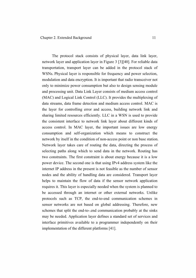
The protocol stack consists of physical layer, data link layer, network layer and application layer in Figure 3 [3][40]. For reliable data transportation, transport layer can be added in the protocol stack of WSNs. Physical layer is responsible for frequency and power selection, modulation and data encryption. It is important that radio transceiver not only to minimize power consumption but also to design sensing module and processing unit. Data Link Layer consists of medium access control (MAC) and Logical Link Control (LLC). It provides the multiplexing of data streams, data frame detection and medium access control. MAC is the layer for controlling error and access, building network link and sharing limited resources efficiently. LLC in a WSN is used to provide the consistent interface to network link layer about different kinds of access control. In MAC layer, the important issues are low energy consumption and self-organization which means to construct the network by itself in the condition of non-access point or non base station. Network layer takes care of routing the data, directing the process of selecting paths along which to send data in the network. Routing has two constraints. The first constraint is about energy because it is a low power device. The second one is that using IPv4 address system like the internet IP address in the present is not feasible as the number of sensor nodes and the ability of handling data are considered. Transport layer helps to maintain the flow of data if the sensor network application requires it. This layer is especially needed when the system is planned to be accessed through an internet or other external networks. Unlike protocols such as TCP, the end-to-end communication schemes in sensor networks are not based on global addressing. Therefore, new schemes that split the end-to-.end communication probably at the sinks may be needed. Application layer defines a standard set of services and interface primitives available to a programmer independently on their implementation of the different platforms [41].
Chapter 2. Extended Background 11

2.1.4 Routing Techniques In most applications, sensor nodes are limited in energy supply and communication bandwidth. Thus, innovative techniques to eliminate energy inefficiencies that shorten the lifetime of the network and efficient use of limited bandwidth are highly required. Such constraints combined with a typical deployment of large number of sensor nodes pose many challenges to the design and management of WSNs and necessitate energy-awareness at all layers of the networking protocol stack. At the network layer, it is desirable to find ways for energy-efficient route discovery and relaying of data from sensor nodes to the base station so that the lifetime of the network is maximized. The design of routing protocols in WSNs is influenced by many challenging factors which should be overcome before efficient communication can be achieved in WSNs. The overview of the routing challenges and design issues that affect the routing process in WSNs has been proposed [33]. Routing protocols in WSNs are dependent on the Protocol-Operation and Network-Structure. A routing protocol is considered adaptive if certain system parameters can be controlled in order to adapt to current network conditions and available energy levels. Furthermore, these protocols are classified with multipath-based, query-based, negotiation-based, QoS-based, or coherent-based routing techniques depending on protocol operation [3][15].
Multipath-based Routing: The fault tolerance by the likelihood that an alternate path exists when the primary path fails is increased by maintaining multiple paths between source and destination at the expense of increased energy consumption and traffic generation. An example is Directed Diffusion (DD).
Chapter 2. Extended Background 12

Query-based Routing: The destination nodes propagate a query for data from a node through the network, a node with this data sends the data that matches the query back to the node that initiated it. An example is Rumor routing.
Negotiation-based Routing: Use Negotiation in order to eliminate redundant data transmissions. Communication decisions are also made based on the resources available. For example, there is Sensor Protocols for Information via Negotiation (SPIN).
QoS-based Routing: When delivering data, the network balances between energy consumption and data quality through certain QoS metrics as delay, energy or bandwidth. An example is Sequential Assignment Routing (SAR).
Coherent-based Routing: The entity of local data processing on the nodes distinguished between coherent (minimum processing) and non-coherent (full processing) routing protocols.
In general, routing in WSNs is divided into flat-based routing, hierarchical-based routing, and location-based routing depending on the network structure as follows [33].
Flat-based Routing: All nodes are typically assigned equal roles or functionality. Since data is being requested through queries, attributed-based naming is necessary to specify the properties of data. For examples, there are SPIN, DD, Rumor routing, and Gradient-based Routing
Hierarchical (Cluster-based) Routing: Nodes will play
Chapter 2. Extended Background 13
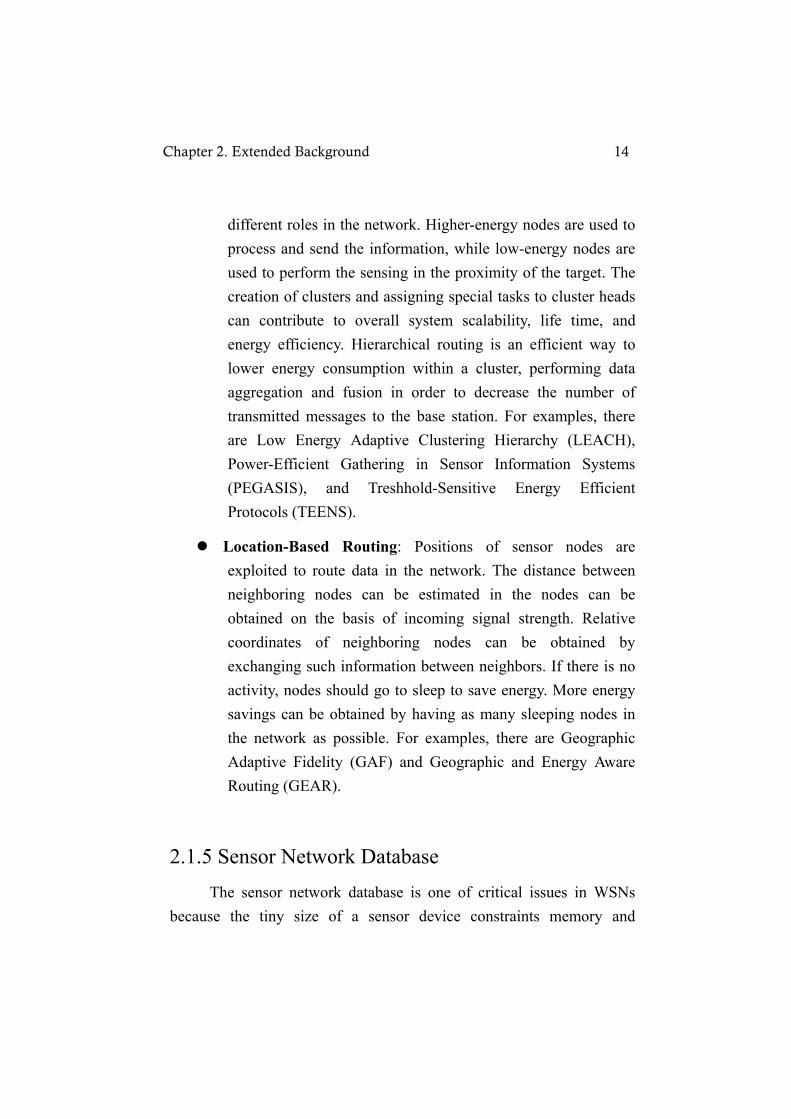
different roles in the network. Higher-energy nodes are used to process and send the information, while low-energy nodes are used to perform the sensing in the proximity of the target. The creation of clusters and assigning special tasks to cluster heads can contribute to overall system scalability, life time, and energy efficiency. Hierarchical routing is an efficient way to lower energy consumption within a cluster, performing data aggregation and fusion in order to decrease the number of transmitted messages to the base station. For examples, there are Low Energy Adaptive Clustering Hierarchy (LEACH), Power-Efficient Gathering in Sensor Information Systems (PEGASIS), and Treshhold-Sensitive Energy Efficient Protocols (TEENS).
Location-Based Routing: Positions of sensor nodes are exploited to route data in the network. The distance between neighboring nodes can be estimated in the nodes can be obtained on the basis of incoming signal strength. Relative coordinates of neighboring nodes can be obtained by exchanging such information between neighbors. If there is no activity, nodes should go to sleep to save energy. More energy savings can be obtained by having as many sleeping nodes in the network as possible. For examples, there are Geographic Adaptive Fidelity (GAF) and Geographic and Energy Aware Routing (GEAR).
2.1.5 Sensor Network Database The sensor network database is one of critical issues in WSNs because the tiny size of a sensor device constraints memory and
Chapter 2. Extended Background 14

managing data in a device limits energy efficiency. Ten years ago, there were satellites, traffic controllers to provide traffic information and Radio Frequency Identification (RFID) to supply simple identity information to aggregate data through sensing. However, there was no database issues related in such sensing devices because their sensors are not necessary to make networks. In other words, they did not have an efficient energy problem that was caused by the radio communication and the complexity level of collecting information was low. Compared with them, a recent smart sensor which has the sensor unit to get new information, computing unit to analyze received data, radio communication unit to supply analyzed information and power unit can collect data in real time. Additionally, the wireless communication can make communication among recent smart sensor nodes which can analyze collected data by themselves. As the capability of sensor nodes is improved and the network of them is built up, distributed database has started to be applied to WSNs. In the sensor network database, it assumes that each sensor is a tiny database or stream information collected from each sensor is a table of the database. Sensor network database, considering limited resource and dealing with the efficient query process, is called embedded and self organizing database [28]. Making query processor is the main purpose of sensor network database system not only to maximize accuracy and rapidity of a query but also to minimize the energy consumption of sensor nodes. Based on query processor of sensor database, local storage, external storage, and data-centric storage are divided by where sensing information is stored [28].
Local storage: the way to store data aggregated by each sensor in their own storage. In order to get the query result a user wants, a user does flooding queries to sensor nodes and each node that conducts queries send the result to user.
Chapter 2. Extended Background 15

External storage: the way to flood sensing information from sensor nodes to the base station. Because all sensing data are stored and query process is conducted in the server, there is no transmission overhead to flood queries to sensor nodes. In other words, the lifetime of a node decreases as each node wastes lots of energy in the process of flooding data for the the server to gather sensing information.
Data-centric storage: the way on which local storage and external storage are mixed. After analyzing sensing information from nodes and then deciding by a special feature of information values, the data are sent to the header node of a group which stores all data of the inner group.
2.2 Design Process of an Interactive System The design process for an interactive system is performed by an observation, bodystorming and brainstorming, making personas and scenario, doing sketch and prototype and evaluation. ●Bodystorming and Brainstorming In the beginning of the design process, it is so important to understand the context sufficiently and choose the place to observe impartially. It would be affected in all process of design due to wrong data made by wrong observation. The observation helps to create idea and first step to advance easily. Cooper [4] said that the benefits of a method called bodystorming is for carrying out design sessions in the original context, ‘in the wild’, instead of the office. It is to understand and discover the specific physical, social, interactional and psychological contextual factors with mind and body, as well as to provide immediate feedback for generated design idea in terms of seeing
Chapter 2. Extended Background 16

the context directly and a more accurate understanding. Brainstorming is also freely to make up and exchange idea from their own experience. The important thing is that bodystorming and brainstorming process is not for discussing, but for just generating ideas. ● Personas Personas provide a powerful tool for understanding user needs, differentiating between different types of users, and prioritizing which users are the most important to target in the design of function and behavior [5]. The process of making personas is given as follows: After doing interview with people, interviewees are classified by the similarity of the answers. Through one group having the largest number of people with similar answers primary persona is created and secondary persona is made from the second small group. Cooper [4] said that personas helped us determine what a product should do and how it should behave. Persona goal and tasks provide the basis for the design effort [5]. Making primary personas and scenario definitely get not only design concept but also detail functions which is implemented by user’s need for primary persona. When the time comes to test with users, personas support a powerful check tool in a stronger design base line because the practical goal is already recognized for users in persona. They would be strengths of personas as a design tool. The self-referential design which occurs designers or developers project their own goals, motivations, skills and mental models onto the design model of a product should be avoid [5]. Many designers or developers unconsciously focus on not designs for users, but designs for easy implementation. The personas method will be improved by getting exact and impartial information of the target group and judging practical goals carefully because the aim of personas is to generate and communicate the requirement of users which is deeply related to product a usable system or service.
Chapter 2. Extended Background 17

● Sketching Mark D. Gross [6] said that sketching is commonly used in early design in both engineering and artistic domains. In these domains, sketching allows an architect, engineer, or artist to quickly and approximately specify a design. It is an estimate of appearance and behavior (‘look & feel’) which are intended and used to elicit, communicate, and verify requirements on functions and usability. Doing sketch does not take long time and facilitates to refine, to approach to specific design before prototyping and to apply a design concept in the interactive system. However, designers or developers can not verify about errors, know satisfaction of users, as well as do usability test with only sketch because they could not see the real action of the artifact function in the sketch. The sketch, both as activity and as a form of representation, occupies a definite and well-understood place in the phrase of a design process because sketching provides a familiar graphical representation for users [7]. ● Prototyping and Evaluation Prototypes are experimental and incomplete designs which are cheaply and fast developed. Prototyping, which is the process of developing prototypes, is an integral part of iterative user-centered design because it enables designers to try out their ideas with users and to gather feedback [8]. The Prototyping gives a kind of simulation of the system to test it. It appeared to behave as a real system although they only showed some scenes. The simulation was restricted by some predefined tasks, and the user interacts with the system. The advantage of prototyping is to involve the users in testing design ideas and get their feedback in the early stage of development, thus to reduce the time and cost. It provides an efficient and effective way to refine and optimize interfaces through discussion, exploration, testing and iterative revision
Chapter 2. Extended Background 18
[9]. The role that the informal evaluation of GUI has played in the design of the prototype is to expose misunderstandings between users and developers through evaluation. Early evaluation can be based on faster and cheaper prototypes before starting the final implementation. The prototypes can be done several times until a better understanding of the user interface design has been achieved by efforts of both the designers and the users.
2.3 Activity Theory Nardi [29] said that the object of activity theory is to understand the unity of consciousness and activity. AT incorporates strong notions of intentionality, meditation, collaboration and development in construction consciousness. Activity theorists argue that consciousness is not a set of discrete disembodied cognitive acts (decision making, classification, remembering), and inextricably embedded in the social matrix of which every person is an organic part. This social matrix is composed of people and artifacts. Artifacts may be physical tools or sign systems such as human language. Understanding interpenetration of the individual, other people, and artifacts in everyday activity is the activity theory. Through analyzing the action of user, artifacts and social situation, AT can provide a broad conceptual framework used to describe the structure, development and the context of tasks [10]. AT has five basic properties as below [11].
Object-orientedness: Actions are goal directed processes to fulfill the object.
Hierarchical structure of activity: Interaction between human begins and the world is organized into functionally subordinated hierarchical levels.
Chapter 2. Extended Background 19

Distinction between internal and external activities: Any activity has an internal and external side relating to each other.
Mediation: Human activity is mediated by a number of tools.
Continuous Development: Both the activity and used tools are constantly reshaped.
Figure 4. An Extended model of Activity Theory
Subject is the individual or group of actors in the activity; objects are artifacts produced by the system; tools and signs mediate the activity; rules refer to explicit or implicit regulations that constrain activity; individuals are concurrently members of different communities; division of labor represents the horizontal division of tasks or vertical division of power and status. Production of the object is oriented by the outcome or intention of the activity system [10]. The interpretations of user actions and relationship among components present the concept and characteristics of an interactive application. This extended model of AT would be main method in the modeling of WSN GUI application.
Chapter 2. Extended Background 20

Chapter 3
Design of WSN System
3.1 Personas Before sketching, we made primary and secondary persona to represent classes of users in the context and to justify user models. Personas are user models as specific, individual humans, not actual people but they are synthesized from observation of real people. It provides the requirement of the user to designers and developers for system concepts. The primary and secondary personas of WSN system are below:
Primary Persona
Name: Sandy Age: 24 Occupation: employee in the Factory
Description Sandy is working in the semiconductor plant. The pure silicon is made by her department. For making single crystal, temperature and humidity are very important conditions in the plant. Temperature should keep between 20°C and 25°C and humidity needs to be
Chapter 3. Design of WSN System 21

between 10% and 15%. One of her work is responsible for checking and keeping the conditions of her department. She moves around to check 5 scales of temperature and humidity once per 20 minutes in her department. If temperature and humidity are not proper for the plant condition, she uses air conditioners to keep the appropriate condition. She has a lot of works and is always busy. Sometimes, she forgets to check them because of other busy works or gets stressful to check them once per 20 minutes and record data. She hopes that some system or another person checks it instead of her.
Practical Goals
Check & Record temperature and humidity instead of her Turn on air conditioners by temperature and humidity automatically to maintain regular conditions.
Personal Goals
To get rid of her stress To help her with some system.
Secondary Persona
Name: Perry Age: 27 Occupation: Ph D. student
Description Perry is working in Automatic control Lab, KTH as a Ph D. student. He researches the protocol design and implementation for Wireless Sensor Networks. Therefore, he is very good at using computer application and already has background of WSNs. He gets the results as text data after testing his design and implementation but he also wants to get the results as graphical data.
Chapter 3. Design of WSN System 22

Additionally, he hopes to manage all of sensor nodes on which his protocol is embedded in the test bed at a glance.
Practical Goals
Represent the result of his design and implementation more graphically Manage test bed at a glance.
Personal Goals
To test and get the result more easily.
Through two personas, Graphic User Interface (GUI) application and the database to save the records are needed for making WSN system. More graphic application helps users recognize the problem and use WSN system easily. WSN system is mixed up for functions used by two kinds of people; normal users like Sandy, who can observe some problems with an software application, and administrator or protocol designer of WSNs like Perry, who can observe and control WSNs.
3.2 Applying Activity Theory Activities, actions and operations make up the three levels of activity [12]. Activities consist of distinct actions or series of actions. We construct Figure 5 in order to better understand about our results which we find through personas for WSN system. In the activity level, we focus on how to work on WSN system. As shown in Figure 5, three main groups of actions constitute the whole process in the actions level. The groups consist of “Monitoring” of which functions user and administrator use, “Collecting context information” by sensor nodes, and “Controlling other devices” followed by “Monitoring” and “Collecting context information”. It means other
Chapter 3. Design of WSN System 23
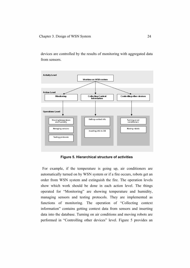
devices are controlled by the results of monitoring with aggregated data from sensors.
Figure 5. Hierarchical structure of activities
For example, if the temperature is going up, air conditioners are automatically turned on by WSN system or if a fire occurs, robots get an order from WSN system and extinguish the fire. The operation levels show which work should be done in each action level. The things operated for “Monitoring” are showing temperature and humidity, managing sensors and testing protocols. They are implemented as functions of monitoring. The operation of “Collecting context information” contains getting context data from sensors and inserting data into the database. Turning on air conditions and moving robots are performed in “Controlling other devices” level. Figure 5 provides an
Chapter 3. Design of WSN System 24

outline for the implementation of WSN system. Action levels can be Java class and operation level can be the methods of Java class. They are more dedicated about functions and screen shots through each activity system model as below:
Figure 6. Activity system model in Activity level
Figure 6 shows activity system model of an activity level, “Working on WSN system”. Activity System model of an activity level illustrates an overall outline and the result of this system. According to extended activity system model of Engeström [31], we put at the center the user/administrator. Through personas, the subject would be a user (Sandy) and an administrator (Perry). The object of his/her activity is to operate WSN system and outcomes include monitoring conditions, collecting context information as well as controlling other devices. The tools that mediate the activity involve sensors, other devices like robots or air conditioners, and the database to insert the data from sensors. The community consists of colleagues of the subject working in the semiconductor plant and the division of labor determines the task of community. Rules constrain activity. It is one of critical issues to
Chapter 3. Design of WSN System 25
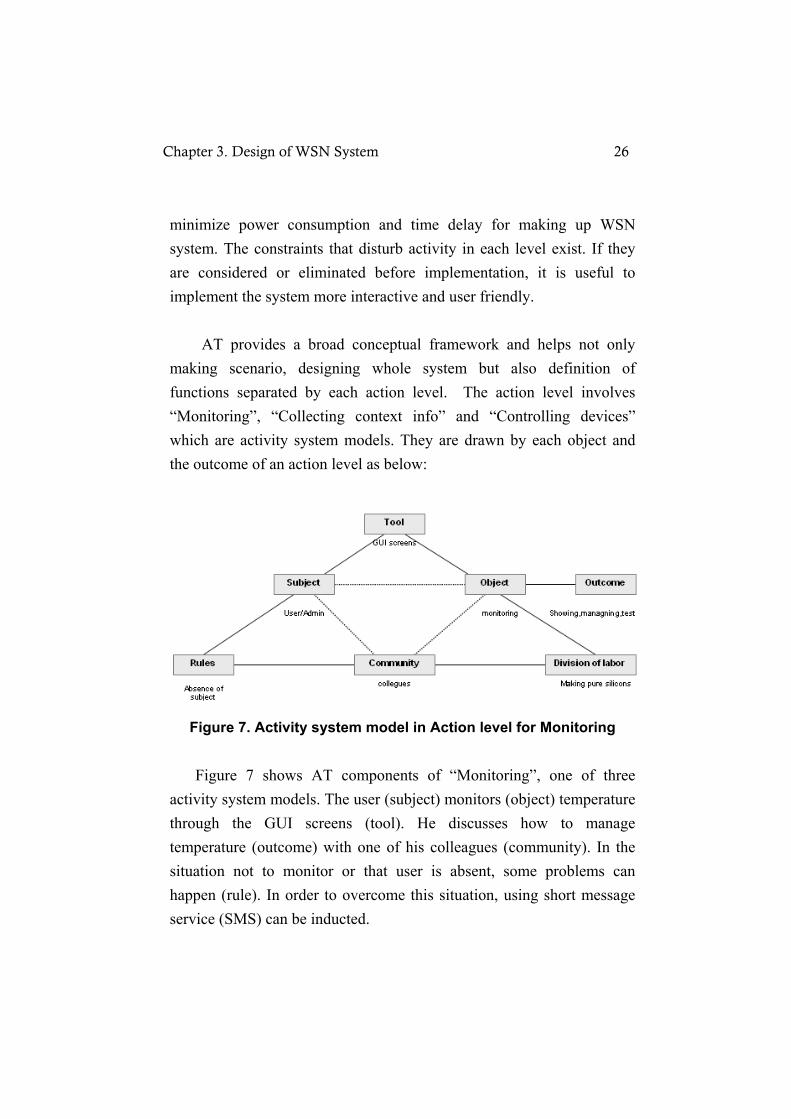
minimize power consumption and time delay for making up WSN system. The constraints that disturb activity in each level exist. If they are considered or eliminated before implementation, it is useful to implement the system more interactive and user friendly. AT provides a broad conceptual framework and helps not only making scenario, designing whole system but also definition of functions separated by each action level. The action level involves “Monitoring”, “Collecting context info” and “Controlling devices” which are activity system models. They are drawn by each object and the outcome of an action level as below:
Figure 7. Activity system model in Action level for Monitoring Figure 7 shows AT components of “Monitoring”, one of three activity system models. The user (subject) monitors (object) temperature through the GUI screens (tool). He discusses how to manage temperature (outcome) with one of his colleagues (community). In the situation not to monitor or that user is absent, some problems can happen (rule). In order to overcome this situation, using short message service (SMS) can be inducted.
Chapter 3. Design of WSN System 26
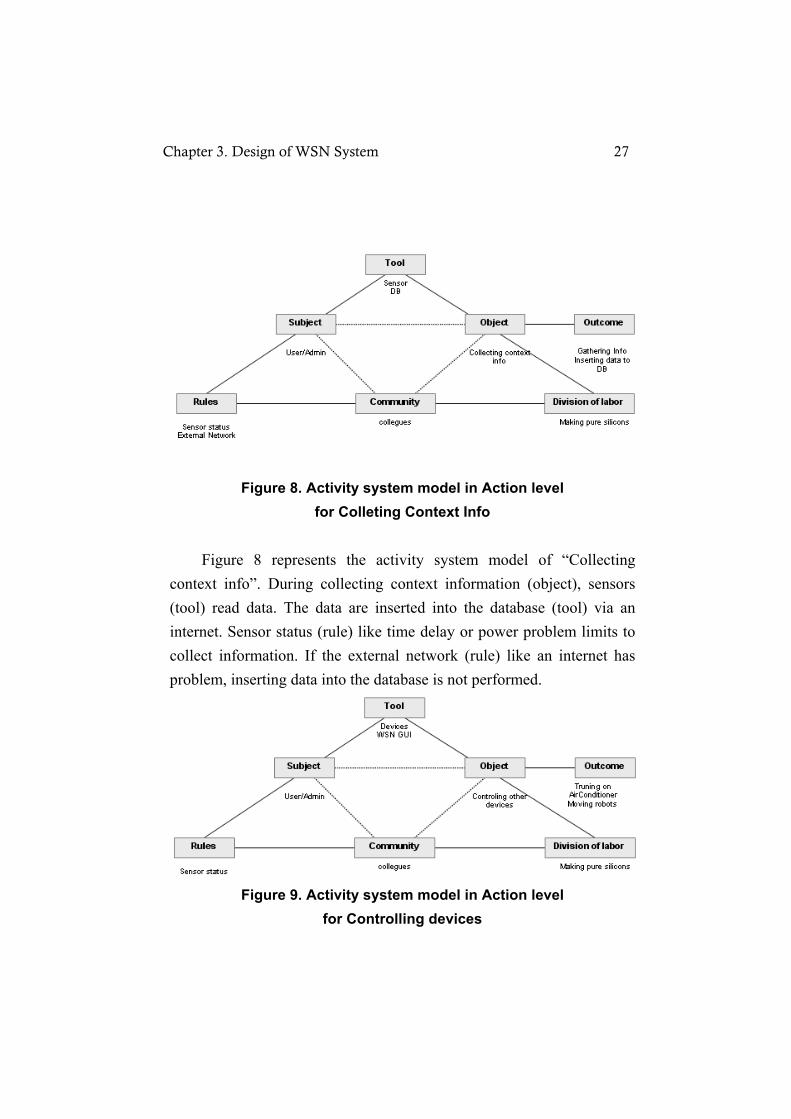
Figure 8. Activity system model in Action level for Colleting Context Info
Figure 8 represents the activity system model of “Collecting context info”. During collecting context information (object), sensors (tool) read data. The data are inserted into the database (tool) via an internet. Sensor status (rule) like time delay or power problem limits to collect information. If the external network (rule) like an internet has problem, inserting data into the database is not performed.
Figure 9. Activity system model in Action level for Controlling devices
Chapter 3. Design of WSN System 27
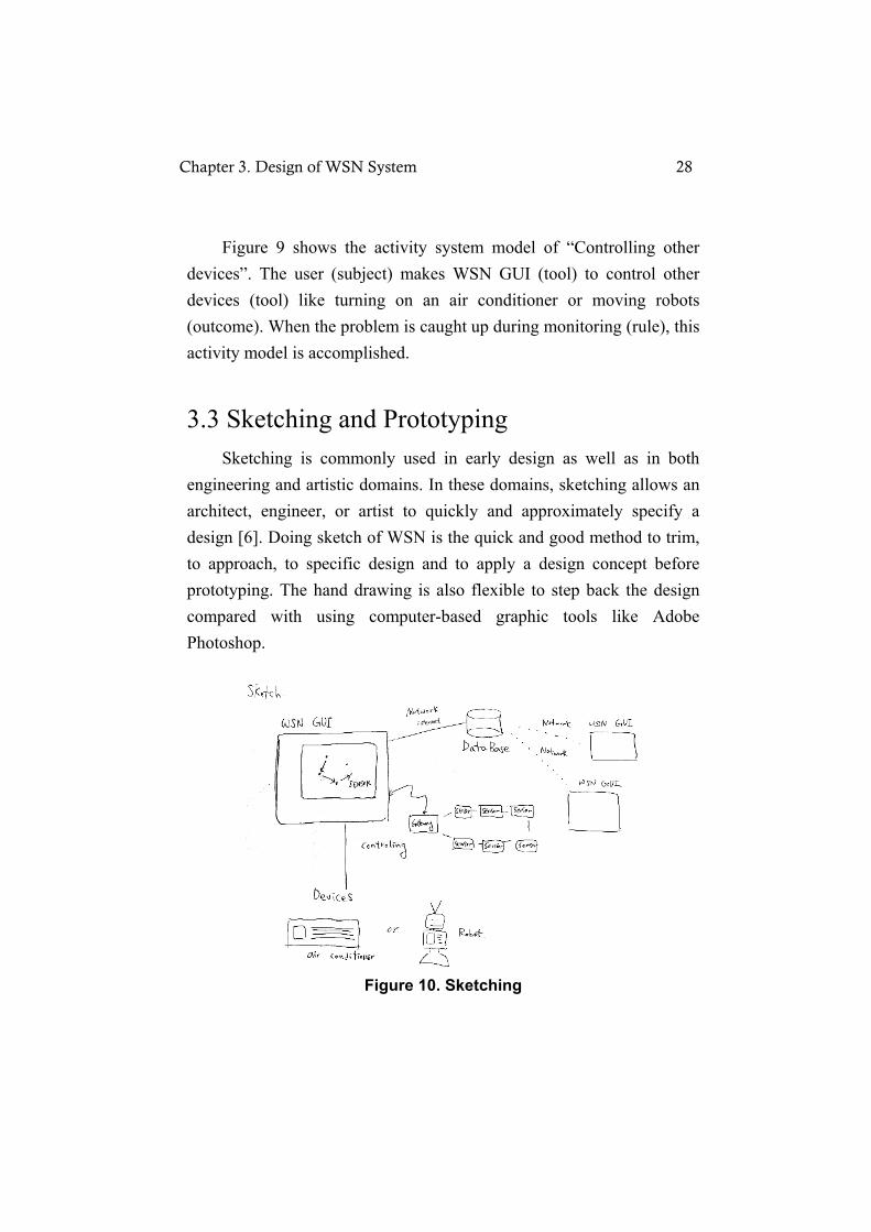
Figure 9 shows the activity system model of “Controlling other devices”. The user (subject) makes WSN GUI (tool) to control other devices (tool) like turning on an air conditioner or moving robots (outcome). When the problem is caught up during monitoring (rule), this activity model is accomplished.
3.3 Sketching and Prototyping Sketching is commonly used in early design as well as in both engineering and artistic domains. In these domains, sketching allows an architect, engineer, or artist to quickly and approximately specify a design [6]. Doing sketch of WSN is the quick and good method to trim, to approach, to specific design and to apply a design concept before prototyping. The hand drawing is also flexible to step back the design compared with using computer-based graphic tools like Adobe Photoshop.
Figure 10. Sketching
Chapter 3. Design of WSN System 28

Figure 10 is a hand drawing of design ideas for an overall WSN system according to activity system models of the activity level in AT (see Figure 6). It expresses 3 parts, which are monitoring, collecting context information and controlling other devices, in the action level. Prototype is simulation of the system to evaluate it simply and examine predefined task before real development. Besides, it enables designers to try out their ideas with users and to gather feedback [8]. Especially, the function design of each page referred activity system model for monitoring in action level (See Figure 7). In order to get the feeling as if using real system, we made out the prototype using MS-PowerPoint which has various functions such as link, slide show and drawing graphically to show up GUI. It gave an efficient and effective way to trim a design through several tests and discussion as well as to make iterative revision. We drew up five revisions while prototyping. The Figure 11.a and Figure 12.a present the 1st version of prototyping. The Figure 11.b and Figure 12.b present the last version of prototyping. Through five revision and discussion, it was changed as more insightful and graphical user interface.
a. 1st version b. last version
Figure 11. The comparison of Prototyping versions
Chapter 3. Design of WSN System 29

In Figure 11, the network map showing sensor nodes changed wider and colorful to recognize map screen at a glance.
a. 1st version b. last version
Figure 12. Menu button (a) VS Hierarchical folder menu (b)
Figure 12 shows that menu buttons were also changed with a hierarchical folder menu representing WSN GUI structure in the left side.
All WSN GUI prototyping organized 13 screens. Through the slide show of MS-PowerPoint, all buttons, link and moving page actually work for simulation to check and test basic interface like a real system. It also guides to implement GUI, for examples, which component of JAVA Swing to implementation for visual scenes is applied or how to find appropriate java classes to perform software. In real implementation, the component which is called CardLayout in Java Swing was used to express that screen is shifted when one of menu is clicked in left side. A CardLayout object is a layout manager for a container. It treats each component in the container as a card. Only one card is visible at a time, and the container acts as a stack of cards. In prototyping version when
Chapter 3. Design of WSN System 30

menu is clicked, menu side is not shifted screens of the right side are changed like showing one card at a time in the stack of card. That is why CardLayout component is selected as the method of changing page. Accordingly, we believe that prototyping makes not only detailed idea to the process of implementation but also possible to test trying out various ways before starting implementation. Figure 13 is main PPT pages of last prototyping version of WSN GUI. Figure 13.a illustrates WSN GUI structure and menu contents. Figure 13.b is an overall map of the status of sensor nodes. Circles represent sensor nodes, the green box represents the base station and the color boxes except for the green box mean temperature and humidity around sensor nodes in Figure 13.b. A hierarchical folder menu representing WSN GUI structure appears in Figure 13.c which has buttons to move the next screen with introductions of WSN protocols in a next screen. The Figure 13.d for a normal user includes network topology map of clustered nodes and pops up the chart of average value in each cluster when C1 button is pressed. There are some more functions like an energy graph, request panel and chart panel in Figure 13.e and Figure 13.f for an administrator. The sliders of request panel are available to change the value of each item. When the mouse has released the slider, the request is sent to sensor nodes. Figure13.f shows that the chart of each node is popped up in the administrator screen when each node is double-clicked.
Chapter 3. Design of WSN System 31

a. WSN GUI Structure b. First big map
c. The explanation of next menu d. user screen
e. administrator screen f. chart screen Figure 13. Prototyping
Chapter 3. Design of WSN System 32

Chapter 4
Implementation of
WSN System
4.1 Hardware Technologies Sensor nodes of WSNs can constitute their own network by themselves. Advanced computing devices like PDA or computers are required to make ad-hoc network using wireless network technology like Bluetooth or wireless LAN. However, the sensor node is not able to use advanced computing devices because of cost and maintenance of WSNs. The requirements of hardware platform for the sensor node are given as below:
Low power for maintenance after deployment
Flexibility and modularity to use effectively in every structure
Cheap price and small size to distribute
Tmote Sky is a node platform for low power, data-rate sensor
Chapter 4. Implementation of WSN System 33

network applications designed with dual goal of fault tolerance and development ease [14]. Designed at the University of California, Berkeley, it is the successor of the popular TelosA and TelosB research platforms The Tmote Sky platform offers vertical integration between the hardware and an operating system, TinyOS. There are integrated sensors, radio, antenna, microcontroller, and programming capabilities in Tmote Sky module. It is equipped with a MSP430 microcontroller which offers 10k byte RAM and 48k byte flash programmable ROM from the Texas Instruments MSP430 family of low-power 16-bit microcontrollers. In MSP430, wakeup time of Tmote Sky is faster as well as active and sleep current consumption is lower compared with them of Mica. For example, the wake up time of Mica2 is 180µs but the wake up time of Tmote sky is 6µs . The active and sleep power of Tmote sky is 15µW whereas the active and sleep power of Mica2 is 33 µW. It provides an easy-to-use USB protocol from FTDI to communicate with the host computer for programming, debugging and data collection. It is equipped with Chipcon CC2420, an IEEE 802.15.4 compliance radio transceiver for reliable wireless communications [16]. The radio provides fast data rate and robust signal. It is under the control of the microcontroller through the Serial Peripheral Interfaces (SPI) port and can be shut off for low power duty cycled operation. It has an integrated onboard antenna with 50m range indoors and up to 125m range outdoor which is internal Inverted-F microstrip antenna, a pseudo omni directional antenna. It includes the integrated ADC, DAC, Supply Voltage Supervisor, DMA controller. Optional integrated humidity, temperature and light sensors which it has are manufactured by Sensiron AG, produced using a CMOS process. Tmote Sky supports TinyOS 1.x and TinyOS 2.0 [3][15].
Chapter 4. Implementation of WSN System 34

4.2 Software Technologies
4.2.1 TinyOS The traditional operating system characteristics are high memory usage, separated kernel and user space, no energy limitation, enough resource, and monolithic event processing that means multi-thread structure in which many processors and threads are used. However, the operating system for sensor networks requires robustness, low resource energy, diverse service implementations, hardware evolution and adaptability in many applications [15]. TinyOS satisfies four requirements for the operating system of sensor networks as below [37]:
Limited resources: OS size should be small because sensor network OS requires small size, low cost and low consumption. TinyOS size is smaller than 400 bytes and has code optimization.
Reactive Concurrency: TinyOS supports concurrency to handle tasks like sensor data and routing in real time and check the race conditions which happens for race detection. The overhead of context switches is low and it is designed to consider real time constraints while managing a lot of sensor data
Flexibility: It should work in several hardware and supports minute modularity. TinyOS has not only higher reusable feature due to component based model but also more simple transplant as hardware/software transparency. If interfaces in the same component do “provides” and “uses”, it is easy to add or delete new components and does not impact other components because all codes are written on component based.
Chapter 4. Implementation of WSN System 35

Low Power: TinyOS supports power management interfaces and uses CPU power very effectively.
TinyOS developed by the University of California, Berkeley, is the most popular operating system for WSNs which is resource-constrained component-based, event-driven and networked embedded systems [17]. It is important to use resources effectively in a restricted memory space and support processor concurrency because of the extremely limited resources in the small physical size. TinyOS has basic concepts to overcome constraints of WSNs. Firstly, all reusable components are utilized from hardware abstraction to high level software. Each component like messaging interacts with another component through the interface which is made up of input/output command and event. Secondly, the system consists of several state-machines and each component represents their status, component command or event handler. It quickly transfers one status to another status with the features of non-blocking and non polling. Lastly, when a node wakes up for an event, it has to execute the related action as fast as possible, then it goes back to sleep status to decrease unnecessary power consumption while CPU is not used. The TinyOS development environment allows various device programmers to program each device with a unique address attribute without compiling the program code each time. The TinyOS system, libraries and applications are written in nesC, an extension of C that was designed for programming embedded systems [3][15] and static language that does not allocate dynamic memory. It makes effective code that software requires and performs optimization through analyzing whole source code for stability. A component-based language, the nesC supports the event based concurrency model of TinyOS.
Chapter 4. Implementation of WSN System 36

4.2.2 Protocol Design In reference [3], considering the energy constraint and processing resources of WSNs, joint optimization and design of networking layers (cross-layer design) stands as the most promising alternative to inefficient traditional layered protocol architectures. The central ideal of cross-layer design is to optimize the control and exchange of information over two or more layers to achieve significant performance improvements by exploiting the interactions between various protocol layers. A Semi-random protocol (SERAN) is one of cross-layer approaches. SERAN is a clustered two-layer protocol based on a semi-random approach. It combines randomized and deterministic components to jointly define routing and MAC layer. It does not have cluster heads and the related problems. It uses a Hybrid TDMA/CSMA MAC protocol. The TDMA scheme is implemented at cluster level and reduces the wake up rate, while the CSMA provides roubustness over unreliable channels and an acknowledgement-bases contention scheme allows reducing duplicated packets. A similar double nature is in the routing algorithm. The combined result is a high reliability and good energy saving. For these reason, SERAN protocol is embedded on the node in this research.
4.2.3 Java Swing Swing is the strong GUI tool kit that Sun Microsystems is developing to enable enterprise development in Java. By enterprise development, programmers can use Swing to create large-scale Java applications with a wide array of powerful components. In addition, these components to control their appearance and behavior can easily be
Chapter 4. Implementation of WSN System 37

extended and modified. Swing is part of a larger family of Java products known as the Java Foundation Classes as well as design aspects from IBM Taligent division and Litghthouse Design. It requires at least JDK 1.1.5 to run [18]. Java Swing features are the following [18][19]:
Swing includes that all the features of AWT which stands for Abstract Window ToolKit to support GUI Java programming and provides a high level of abstraction for the Java program. Indeed, implementing a set of Swing GUI components builds on AWT technology and it extensively depends on the event handling mechanism of AWT in spite of defining a lot of events for itself comparatively.
Swing is 100% pure Java certified version of the existing AWT such as Button, Scroll Bar and Label and it has a rich set of higher level components like tree view, list box, tabbed panes, sliders, progress bars, internal frames and text components.
One of the most exciting aspects of the Swing classes is the ability to speak the look-and-feel (L&F), which is for not only design setup and GUI including visible colors, layout and shapes ("Look") but also the working of dynamic component such as buttons, drag and drop, and menus ("Feel") in SW design. Swing can be an aspect of not functional API but graphical API. It allows the user to switch look-and-feels at runtime without having to close to the current applications. Therefore, a user can experiment to see which L&F is best for them with instantaneous feedback.
Most swing components are light-weight, it means components are no reliance on native peers to render themselves. They use simplified graphics primitives to paint themselves on the screen
Chapter 4. Implementation of WSN System 38

and can even allow portions to be transparent. Programmers can directly extend the java.awt.Component or java.awt.Constainer classes when creating lightweight components. Unlike java.awt.Canvas or java.awt.Panel, these classes do not rely on a peer and allow the developer to render quickly to the graphics context of the container. This results in faster, less memory-intensive components than previously available Java.
Compared with AWT, there is additional debugging support for the rendering of their own lightweight Swing components made by developers. It is possible to bind keyboard events to components, defining how they will react to various keystrokes under given conditions. In Swing components, a tooltip is a textual popup that momentarily shows when the mouse put inside the painting region of a component. It gives more information about the component and is very useful for developers.
4.2.4 Java Web Start Java Web Start is an application deployment technology introduced in 2001 to launch the java application in one click from the web browser. It gets over the limitations of web environment in the association of the application and web browser. It freely runs strong applications through network. Furthermore, it gives new paradigm to overcome existing client window programs as managing applications with Java Network Launching Protocol (JNLP) which automatically performs deployment and control of new versions. The process of Java Web Start [42] is in Figure 14. When a user
Chapter 4. Implementation of WSN System 39

clicks on a link that points to a special launch file (JNLP file), it lets the browser to launch Java Web Start, which then automatically downloads, caches, and runs the given Java Technology-based application. The entire process is typically completed without requiring any user interaction except for the initial single click [20].
Figure 14. The process of Java Web start
From a technology standpoint, Java Web Start has a number of key benefits that make it an attractive platform to use for deploying applications. These are summarized as below [21]:
Java Web Start is built exclusively to launch applications written to the Java™ Platform Standard Edition. Thus, a single application can be made available on a Web server and then deployed on a wide variety of platforms, including Windows 98/NT/2000/ME/XP, Linux, and the Solaris™ Operating Environment. The Java platform has proven to be a very robust, productive, and expressive development platform, leading to a significant cost savings because of minimizing development and testing costs.
Chapter 4. Implementation of WSN System 40

Java Web Start supports multiple revisions of the Java™ Platform Standard Edition. Thus, an application can request a particular version of the platform it requires, such as Java SE™ 1.5.0. Several applications can run at the same time on different platform revisions without causing conflicts, and Java Web Start can automatically download and install a revision of the platform if an application requests a version that is not installed on the client system.
Java Web Start allows applications to be launched independently of a Web browser. This is used for off-line operation of an application, where launching through the browser is often inconvenient or impossible. The application is also launched through desktop shortcuts, making launching the Web-deployed application similar to launching a native application.
Java Web Start takes advantage of the inherent security of the Java Platform. Applications run in a protective environment (sandbox) with restricted access to local disk and network resources. It allows the user to safely run applications from sources that are not trusted.
Applications launched with Java Web Start are cached locally. Therefore, a downloaded application is launched on par with a traditionally installed application
Java Web Start is included in Java Runtime Environment (JRE). Java Web Start has three different ways which are from clicking on a link in a web browser, desktop icons / the Start Menu / From the Java Cache Viewer, to launch an application. It connects to Web Server to check whether it is the old version or necessary to update regardless of
Chapter 4. Implementation of WSN System 41
which way is chosen. The client/Desktop computer demands support for the version later than JRE 1.3. Java Web Start is available for Windows 98/NT/2000/ME/XP, the Solaris Operating Environment, and Linux. Any standard Web server deploys applications for the server computer. ● The development process using Java Web Start [42] 1. An application is developed with AWT/SWING 2. Java class files related to an application are bound as jar file to download easily 3. jar file is signed to access local and network resources of an application. 4. The JNLP file in which the information of the application to deploy is written with XML is created 5. JNLP mime type is set up in the web server. 6. The signed jar file and JNLP file are put in the directory of web server where files enable to activate through an internet.
4.3 Implementation of WSN System WSN system, extending WSN GUI application and combining with an internet and a wireless communication network, is built up with Java Web Start and MS-SQL on the web server. To avoid confusion of WSN GUI application versions, they are renamed and defined by how to handle data in this chapter.
O-WSN GUI: This is the base application of others. It directly displays data coming from sensor nodes and does not save data.
I-WSN GUI: This also shows data from sensor nodes but stores data in the database of a web server.
S-WSN GUI: This displays data from the database of a web
Chapter 4. Implementation of WSN System 42

server for the purpose of monitoring on the internet.
They are developed not only to use software applications anywhere but also to track all data since it remains all logs in the database. Furthermore, this research presents that utilizing Java Web Start decreases the development period of WSN system because it does not require implementing web pages such as making HTML and web server pages which spent long time.
4.3.1 Setup for WSN System
Figure 15. Architecture of WSN System
Figure 15 shows how to set up for WSN system. O-WSN GUI connects to only base station to read and show data. I-WSN GUI connects to the base station and an internet because I-WSN GUI shows
Chapter 4. Implementation of WSN System 43

data through the base station as well as stores data in the database of a web server through an internet. S-WSN GUI connects to only internet to displays data from the database of a web server. Web Server is necessary to launch the web browser of S-WSN GUI through the internet and to save the data that I-WSN GUI receives from the base station. For the architecture of Web Server, MS-SQL Server 2005, Java, Apache HTTP Server 2.2 and Tomacat 5.5 are installed on Window server 2005 that supports a web server as an operating system. MS-SQL is a relational database management (RDBMS) to store data. Apache HTTP web server makes an environment to activate web server for users using the web browser. Apache Tomcat is an implementation of the Java Servlet and JavaServer Pages technologies whose specifications are developed under the Java Process [32]. Tomcat makes a useful platform for developing and deploying web applications and web services across a diverse range of industries and organizations.
4.3.2 Implementation of functions and screens As we see Figure 5 in chapter 3.2, AT components of action level become obvious stems for functions of WSN GUI. “Monitoring” implements panels like the map or chart to diversely express received data from sensor nodes. Text data from nodes are converted with graphical data in this part. Scout is responsible for “Collecting context information” to gather data from nodes. “Controlling other devices” is not implemented in this research. The functions corresponding to operation level in Figure 5 become Java methods in each class.
Chapter 4. Implementation of WSN System 44
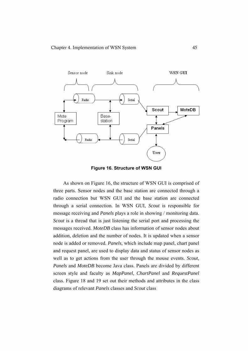
Figure 16. Structure of WSN GUI
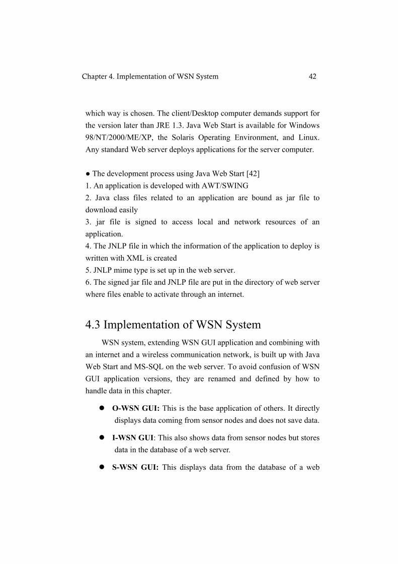
As shown on Figure 16, the structure of WSN GUI is comprised of three parts. Sensor nodes and the base station are connected through a radio connection but WSN GUI and the base station are connected through a serial connection. In WSN GUI, Scout is responsible for message receiving and Panels plays a role in showing / monitoring data. Scout is a thread that is just listening the serial port and processing the messages received. MoteDB class has information of sensor nodes about addition, deletion and the number of nodes. It is updated when a sensor node is added or removed. Panels, which include map panel, chart panel and request panel, are used to display data and status of sensor nodes as well as to get actions from the user through the mouse events. Scout, Panels and MoteDB become Java class. Panels are divided by different screen style and faculty as MapPanel, ChartPanel and RequestPanel class. Figure 18 and 19 set out their methods and attributes in the class diagrams of relevant Panels classes and Scout class
Chapter 4. Implementation of WSN System 45
a. First big map b. The Explanation of next screen
c. User Screen d. Administrator screen Figure 17. The main screens of WSN GUI
In Figure 17, main screens of the implemented application are based on prototyping. Figure 17.a shows the present status of sensor nodes on the map. A black circle is a base station and blue circles are sensor nodes. A variety of color boxes represent the temperature around sensor nodes. Figure 17.b illustrates the explanation of protocol before moving next screen for user and has user button and admin button. If you press the user button, Figure 17.c is shown. Figure 17.d is for an administrator. If each node is selected, the chart window of each node is popped up. The administrator can send some values to sensor nodes using sliders on the right side.
Chapter 4. Implementation of WSN System 46

One of the most important aspects of the Swing classes is the ability to speak the look-and-feel (L&F), which is for not only design setup and GUI including visible colors, layout and shapes ("Look") but also the working of dynamic component such as buttons, drag and drop, and menus ("Feel") in SW design [18]. UIManager registers Look-and-Feel such as the Java™ Look-and-Feel, the CDE/Motif Look-and-Feel, and the Microsoft Windows Look-and-Feel for the interface that makes up Swing pluggable look-and-feel. UIManager.setLookAndFeel(UIMan ager.getSystemLookAndFeelClassName()) means that Look-and-Feel is registered by the system theme of each computer in WSN GUI. Window Look-and-Feel appears in this system because this application is installed on Windows (See Figure 17). ● Panels Classes
Figure 18. Class Diagram of Panels Panels, which include map panel, chart panel and request panel, are
Chapter 4. Implementation of WSN System 47

used to display data and status of sensor nodes as well as to get actions from the user through the mouse events. The different screen style and faculty distinguishes WholePanel, MapPanel, ChartPanel and RequestPanel class. In Figure 18, a box represents one class. It is comprised of the name of class, attributes of class and methods of class. All panel classes create by WholePanel class. The dot arrows mean that MapPanel implements MouseListner interface and RequestPanel implements ChangeListner interface. WholePanel takes the responsibility for how to organize each screen and manage display information of all screens. It also decides the position of components such as button, menu, text and panels. MapPanel draws the topology of sensor nodes with received data on the map. ChartPanel is responsible for draw chart with sensor value. Changing values of sensor nodes are performed by RequestPanel. We explain the important method in panel classes considering the Figure 18 and screens from Code 1 to Code 5. CardLayout cardLayout1 = new
CardLayout();
panel.setLayout(cardLayout1);
layerpanel = new JPanel();
//Seran admin page
layerpanel = createSeranAdmPanel();
panel.add(“panel5”, layerpanel);
//Seran user page
layerpanel = createSeranUsrPanel();
panel.add(“panel4”, layerpanel);
//Seran menu page
layerpanel = createSeranExPanel();
panel.add("panel3", layerpanel);
//monitoring menu page
layerpanel = createMonitExPanel();
panel.add("panel2", layerpanel);
//temperature map page
layerpanel = createBigMapPanel();
panel.add("panel1", layerpanel);
((CardLayout)panel.getLayout()).show(panel,
"panel1");.
Code 1. createAndShowWPanel() method
Chapter 4. Implementation of WSN System 48

Code 1 illustrates createAndShowWPanel() which is the most important method in WholePanel class. WSN GUI frame is comprised by private JFrame frame = new JFrame("WSN GUI"). Five main screens are created on "WSN GUI" frame with using CardLayout class which manages two or more components (usually JPanel instances) that share the same display space. The main screens like overlapping cards are defined in one method, createAndShowWPanel(). Additionally, it defines using panels where we can attach components with JPanel, one of Swing containers, and calls each function implementing its own overall shape and layout. JLabel and JButton class supported by Java are simple and necessary classes for the composition of a screen. The components of JLabel class create labels that can contain text, images, or both. It puts the explanations of panels or the name of buttons. JButton class makes buttons which are simple UI components used to generate events when the user presses them in all screens.
public JPanel createMonitExPanel(){
… mnutreeView(0); …}
public JPanel createSeranUsrPanel(){
… mnutreeView(3); …}
public void mnutreeView(int expandrow){
root = new DefaultMutableTreeNode("WSN");
node1 = new DefaultMutableTreeNode("Localization");
root.add(node1);
Chapter 4. Implementation of WSN System 49

node1 = new DefaultMutableTreeNode("Monitoring");
node2 = new DefaultMutableTreeNode("SERAN");
node3 = new DefaultMutableTreeNode("USER");
node2.add(node3);
node3 = new DefaultMutableTreeNode("ADMIN");
node2.add(node3);
node1.add(node2);
node1.add(new DefaultMutableTreeNode("TDMA"));
root.add(node1);
mnuTree = new JTree(root);
……
mnuTree.addTreeSelectionListener(( new TreeSelectionListener() {
public void valueChanged(TreeSelectionEvent e) {
DefaultMutableTreeNode n =
(DefaultMutableTreeNode)(e.getPath().getLastPathComponent());
String nodestr = (String)n.getUserObject();
if(nodestr.equals("WSN"))
((CardLayout)panel.getLayout()).show(panel, "panel1");
……
else if(nodestr.equals("USER"))
((CardLayout)panel.getLayout()).show(panel, "panel4");
else if(nodestr.equals("ADMIN"))
((CardLayout)panel.getLayout()).show(panel, "panel5");
else
((CardLayout)panel.getLayout()).show(panel, "panel1");}
}
Code 2. MenuTree shape and mnutreeView() method
Code 2 shows menutree, one of important UI in this application. After several prototyping, the left side menu consisting of buttons was
Chapter 4. Implementation of WSN System 50

changed with hierarchical tree folder menu representing WSN GUI structure. CardLayout is activated by mnutreeView() and valueChanged() in WholePanel class. JTree class can build up trees out of several different objects, including a Tree-Model.When one of tree nodes are selected, right side screen shows up by calling mnutreeView() method that consists of drawing tree nodes and appearing each screen connected to a clicked node of menutree by mnuTree.addTreeSelectionListener();. This method calls valueChanged(TreeSelectionEvent e) which is the method of the object of TreeSelectionListener().
private MapPanel UmapPanel,
AmapPanel, mapPanel ;
AmapPanel = new
MapPanel(moteDatabase, chartPanel);
mapPanel = new
MapPanel(moteDatabase, null);
UmapPanel = new
MapPanel(moteDatabase, null);
class MapPanel extends JPanel
implements MouseListener{
public MapPanel(MoteDatabase
moteDatabase, ChartPanel chartPanel )
{……}
public void paint(Graphics g) {……}
private void drawCircleMote(Mote mote,
Graphics2D g2) {……}
public void mouseClicked(MouseEvent e)
{……}
}
Code 3. The panels of the main (mapPanel), user (UmapPanel) and administrator (AmapPanel) & MapPanel Class
Chapter 4. Implementation of WSN System 51
In Code 3, pictures represent the main map which is attached on first screen of this application, map for the user and another map for administrator. Although the looking appearance of user map and administrator map are same, their function is different. It is possible to check the chart of each node in only administrator map. The core UI is map in this application. Three of five screens include MapPanel that displays a map of network. There are the node id, the number of sensing sensor, temperature value sensed by each sensor, colors continuously changed by temperature and the base station (green box) on the map. The map is repainted per a second by paint(), main method is called by Java. drawCircleMote() method draws a node by using a circle, adds a black border if the node is selected (if the user clicks on the node) and draws some text under the node. It also decides color inside the box by defined temperature. Due to which map is used, three objects (UmapPanel, AmapPanel, mapPanel) are created using constructor, public MapPanel(MoteDatabase moteDatabase, ChartPanel chartPanel ) in MapPanel class . Unlike UmapPanel for user and mapPanel in first screen, AmapPanel faculty requires the chart for administrator to check the graph of sensor values when clicked each node. That is why public void mouseClicked(MouseEvent e) is added in MapPanel class. MapPanel class can detect that mouse events notify while user uses the mouse to interact with a component.
Chapter 4. Implementation of WSN System 52

class ChartPanel extends JPanel {
public void paint(Graphics g) {
…
ReadingRecordList readingRecordList;
for (Iterator it=moteRecordList.listIterator(0);
it.hasNext(); ) {
readingRecordList =
(ReadingRecordList)it.next();
drawLine(readingRecordList, g2);
}
…
private synchronized void
drawLine(ReadingRecordList list,
Graphics2D g2) {…}
}
Code 4. Chart shape and ChartPanel class In Code 4, the ChartPanel class is called by AmapPanel when the node is clicked to check the reading value of each sensor node in the administrator screen map. By paint() method, X and Y axis are firstly drawn and then sensor value line is drawn. readingRecordList is an object of ReadingRecodList extending the LinkedList class and is created by time and reading. Note that this panel is painted per every 10 seconds. Code 5 shows the shape of sliders on request panel and RequestPanel class. To send requests from the application to the network, JSlider class which represents a graphical slider is used. When a slider is move, RequestPanel class detects it by ChangeListener() interface. The request is sent in stateChanged() method only when the
Chapter 4. Implementation of WSN System 53

tick mark is released.
public JPanel createSeranAdmPanel(){
……
sleepSlider = new JSlider(JSlider.HORIZONTAL, 0, 100,
Util.dutyCycleToPercent(Constants.DEFAULT_SLEEP_D
UTY_CYCLE));
sleepSlider.addChangeListener(this);
sleepSlider.setMajorTickSpacing(10);
sleepSlider.setMinorTickSpacing(2);
sleepSlider.setPaintTicks(true);
sleepSlider.setPaintLabels(true);
sleepSlider.setBorder(BorderFactory.createTitledBorder("
Sleep Duty Cycle (in %)"));
……
requestpanel.setBorder(BorderFactory.createTitledBorder
("Control"));
requestpanel.setBounds(0, 0, 150,300);
rightPanel.add(requestpanel);
…}
class RequestPanel extends JPanel implements ChangeListener {
public void stateChanged(ChangeEvent e) {
……
sender.add(MoteIF.TOS_BCAST_ADDR,
(int)Constants.SET_SLEEP_DUTY_CYCLE_REQUEST,
Util.dutyCycleToInt((int)source.getValue()),
"Set SleepDutyCycle = "+(int)source.getValue()+"% [Id=broadcast]");
……
}
}
Code 5. Slider shape and RequestPanel class
Chapter 4. Implementation of WSN System 54
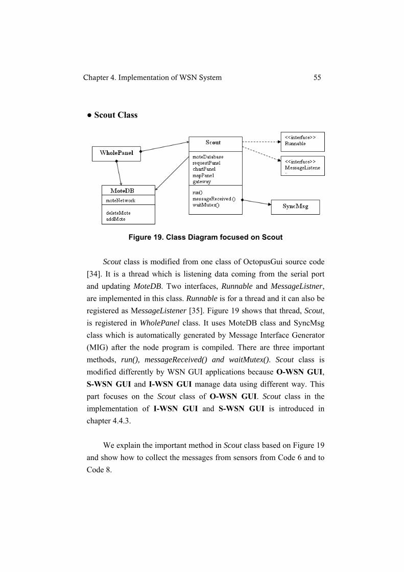
● Scout Class
Figure 19. Class Diagram focused on Scout
Scout class is modified from one class of OctopusGui source code [34]. It is a thread which is listening data coming from the serial port and updating MoteDB. Two interfaces, Runnable and MessageListner, are implemented in this class. Runnable is for a thread and it can also be registered as MessageListener [35]. Figure 19 shows that thread, Scout, is registered in WholePanel class. It uses MoteDB class and SyncMsg class which is automatically generated by Message Interface Generator (MIG) after the node program is compiled. There are three important methods, run(), messageReceived() and waitMutex(). Scout class is modified differently by WSN GUI applications because O-WSN GUI, S-WSN GUI and I-WSN GUI manage data using different way. This part focuses on the Scout class of O-WSN GUI. Scout class in the implementation of I-WSN GUI and S-WSN GUI is introduced in chapter 4.4.3. We explain the important method in Scout class based on Figure 19 and show how to collect the messages from sensors from Code 6 and to Code 8.
Chapter 4. Implementation of WSN System 55

public void run() {
gateway.registerListener(new SyncMsg(),
this);
int mapPanelCounter = 0;
int chartPanelCounter = 0;
while(true) {
try {
Thread.sleep(Util.SCOUT_SLEEP_PERIOD);
} catch (Exception e)
{ e.printStackTrace();}
mapPanelCounter++;
if (mapPanelCounter>=10) {// 1 sec
mapPanel.repaint();
mapPanelCounter=0;
}
chartPanelCounter++;
if (chartPanelCounter>=100) {
// 10 secs
chartPanel.repaint();
chartPanelCounter=0;
}
}
} Code 6. Run() method of O-WSN GUI
Code 6 explains that the main method of Scout class, run(), is called when the thread is started. The gateway is registered as the source of messages which depends on which program is installed on the sensor node and then an infinite loop is started. The thread will sleep and regularly ask for repaint of some panels. It means that the thread just does a loop, sleeping and incrementing a counter with a frequency of 10 Hz (100 ms). The max values of the counters are defined to choose the frequency of repainting the mapPanel and chartPanel. public void messageReceived(int dest_addr, Message msg) {
SyncMsg message = (SyncMsg) msg;
…
localMote = moteDatabase.getMote(message.get_sourceid());
if(localMote != null) {
localMote.setReading(message.get_temperatre());
localMote.setQuality(message.get_humidity());
Chapter 4. Implementation of WSN System 56
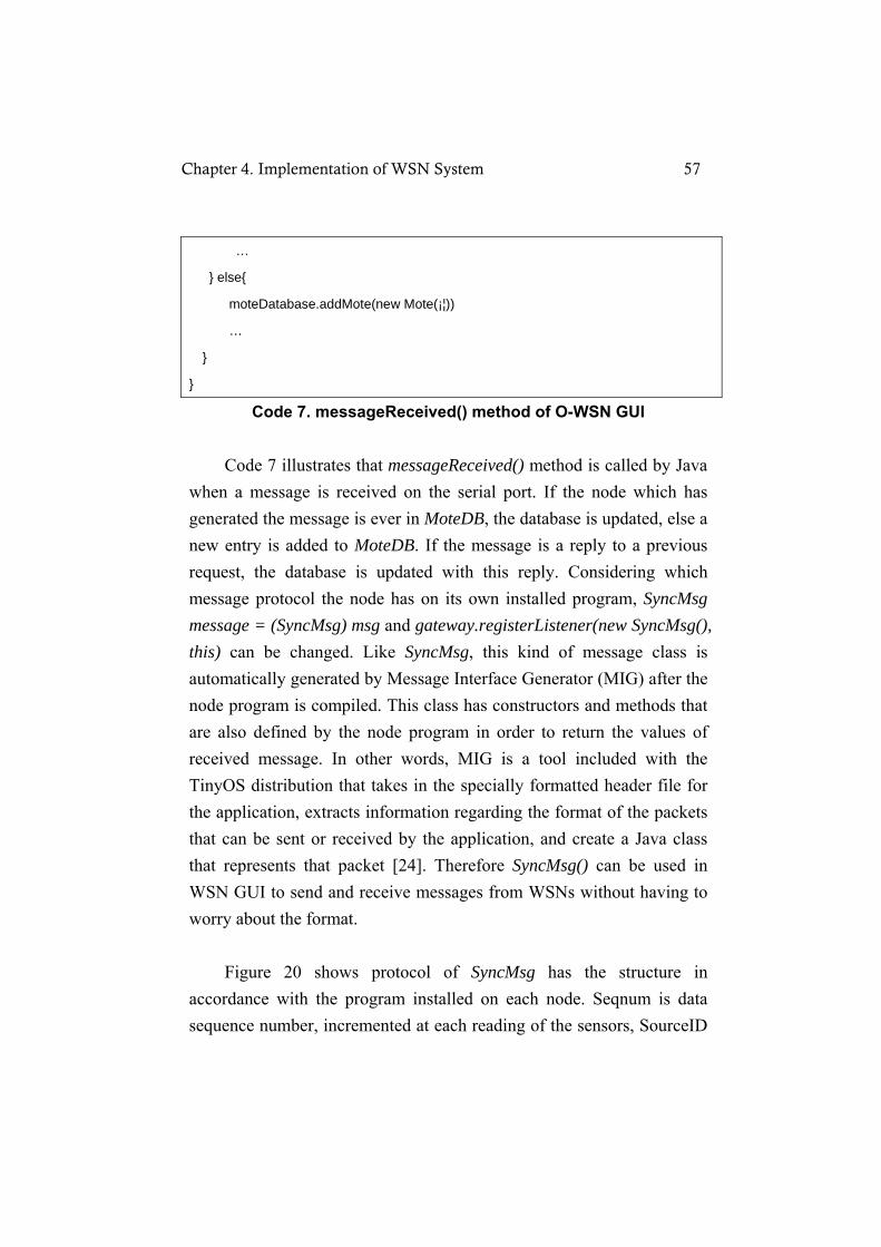
…
} else{
moteDatabase.addMote(new Mote(¡¦))
…
}
}
Code 7. messageReceived() method of O-WSN GUI Code 7 illustrates that messageReceived() method is called by Java when a message is received on the serial port. If the node which has generated the message is ever in MoteDB, the database is updated, else a new entry is added to MoteDB. If the message is a reply to a previous request, the database is updated with this reply. Considering which message protocol the node has on its own installed program, SyncMsg message = (SyncMsg) msg and gateway.registerListener(new SyncMsg(), this) can be changed. Like SyncMsg, this kind of message class is automatically generated by Message Interface Generator (MIG) after the node program is compiled. This class has constructors and methods that are also defined by the node program in order to return the values of received message. In other words, MIG is a tool included with the TinyOS distribution that takes in the specially formatted header file for the application, extracts information regarding the format of the packets that can be sent or received by the application, and create a Java class that represents that packet [24]. Therefore SyncMsg() can be used in WSN GUI to send and receive messages from WSNs without having to worry about the format. Figure 20 shows protocol of SyncMsg has the structure in accordance with the program installed on each node. Seqnum is data sequence number, incremented at each reading of the sensors, SourceID
Chapter 4. Implementation of WSN System 57
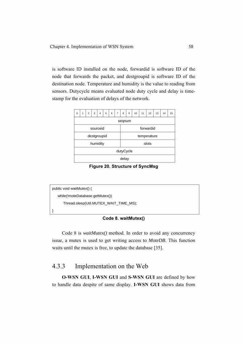
is software ID installed on the node, forwardid is software ID of the node that forwards the packet, and destgroupid is software ID of the destination node. Temperature and humidity is the value to reading from sensors. Dutycycle means evaluated node duty cycle and delay is time-stamp for the evaluation of delays of the network.
0 1 2 3 4 5 6 7 8 9 10 11 12 13 14 15
seqnum
sourceid forwardid
destgroupid temperature
humidity slots
dutyCycle
delay
Figure 20. Structure of SyncMsg public void waitMutex() {
while(!moteDatabase.getMutex())
Thread.sleep(Util.MUTEX_WAIT_TIME_MS);
}
Code 8. waitMutex()
Code 8 is waitMutex() method. In order to avoid any concurrency issue, a mutex is used to get writing access to MoteDB. This function waits until the mutex is free, to update the database [35].
4.3.3 Implementation on the Web O-WSN GUI, I-WSN GUI and S-WSN GUI are defined by how to handle data despite of same display. I-WSN GUI shows data from
Chapter 4. Implementation of WSN System 58
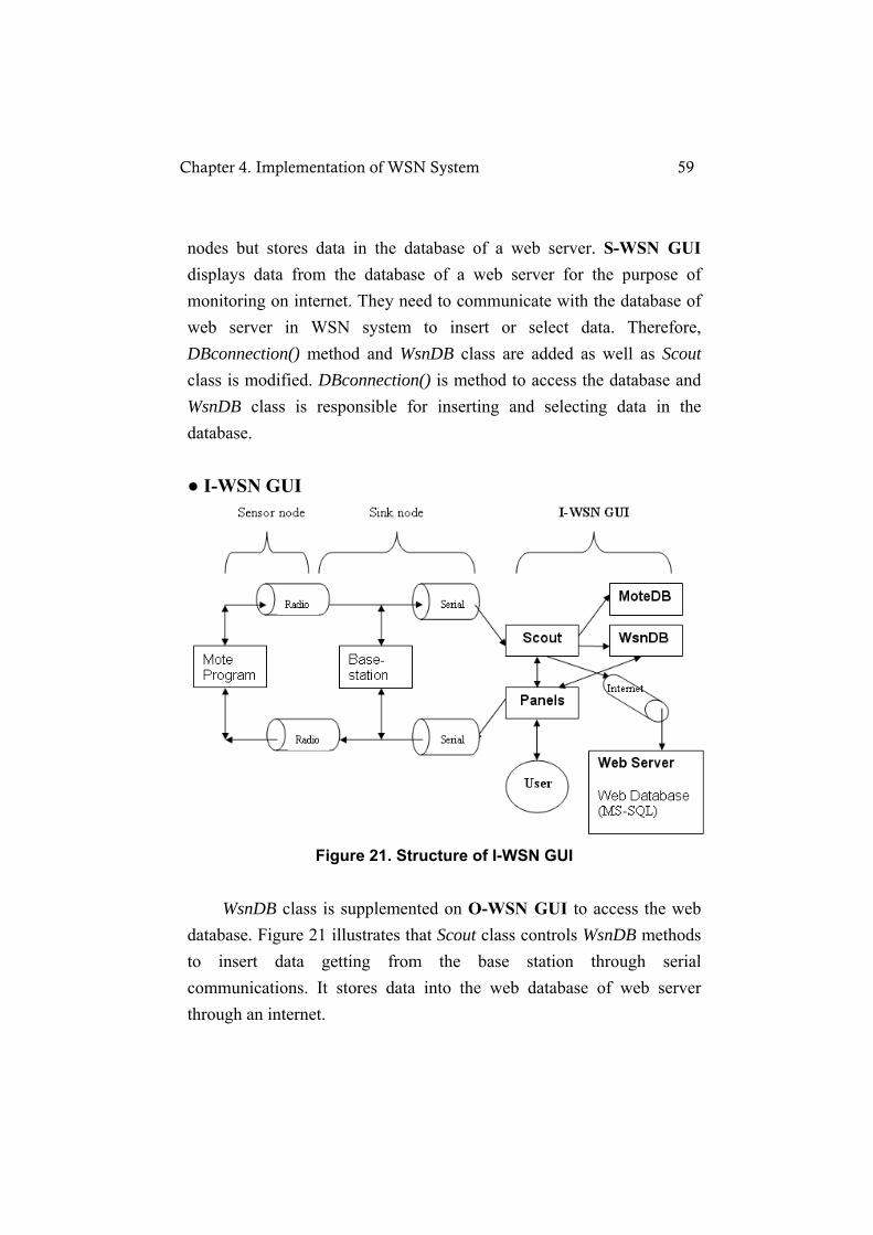
nodes but stores data in the database of a web server. S-WSN GUI displays data from the database of a web server for the purpose of monitoring on internet. They need to communicate with the database of web server in WSN system to insert or select data. Therefore, DBconnection() method and WsnDB class are added as well as Scout class is modified. DBconnection() is method to access the database and WsnDB class is responsible for inserting and selecting data in the database. ● I-WSN GUI
Figure 21. Structure of I-WSN GUI
WsnDB class is supplemented on O-WSN GUI to access the web database. Figure 21 illustrates that Scout class controls WsnDB methods to insert data getting from the base station through serial communications. It stores data into the web database of web server through an internet.
Chapter 4. Implementation of WSN System 59

Figure 22. Class Diagram of I-WSN GUI Based on O-WSN GUI (See Figure 19), the class diagram of I-WSN GUI is changed with the addition of WsnDB class and DBconnection() method in Figure 22. public void DBconnection() {
//for jtds
String url ="jdbc:jtds:sqlserver://localhost:1433/wsn;tds=8.0";
Class.forName("net.sourceforge.jtds.jdbc.Driver");
con = DriverManager.getConnection(url, "sa","ghkrud98");
wsndb= new WsnDB(con);
}
Code 9. DBconnection() method
In Code 9, DBconnection() is a method to help it connects with the database. JTDS is one of JDBC which means java database connectivity. JTDS is a Java API that enables java programs to execute SQL statements. After getting connection between Java and database, the connection (‘con’ variable) sends to WsnDB class. The I-WSN GUI routine of reading data from the base station is same to O-WSN GUI
Chapter 4. Implementation of WSN System 60

process, but the routine of inserting received data into the web database is interposed before showing received data on the screen.
Public void messageReceived(int
dest_addr, Message msg) {
SyncMsg message = (SyncMsg) msg;
…
localMote.setCount(message.get_seqnum
());
rslt = wsndb.insertTbl_Data(
message.get_seqnum (),
message.get_sourceid(),
message.get_destgroupid(),
message.get_forwardid(),
message.get_temperature () );
…
}
public class WsnDB{
public int insertTbl_Data(int _seq_numb,
int _src_idxx, int _grp_idxx, int _fwd_idxx,
int _tmp_read ) {
sql = "INSERT INTO Tbl_Data (seq_numb,
src_idxx, grp_idxx, fwd_idxx, trf_rate,
tmp_read, tim_date) " ;
sql += " VALUES (?, ?, ?, ?, '100', ?,
GETDATE()) " ;
pstmt = db.prepareStatement(sql);
pstmt.setInt(1, _seq_numb) ;
pstmt.setInt(2, _src_idxx) ;
pstmt.setInt(3, _grp_idxx) ;
pstmt.setInt(4, _fwd_idxx) ;
pstmt.setInt(5, _ tmp_read) ;
nResult = pstmt.executeUpdate();
}
}
Code 10. Inserting data into DB & WsnDB class for I-WSN GUI Code 10 illustrates how to manage data to insert into the database using messageReceived() of Scout and WsnDB. messageReceived() simply puts information of each node into localMote variable which is an object of Mote() class in O-WSN application. However, all of the receiving data are performed to save in the table of the web database that is called ‘Tbl_Data’ through SQL statements in WsnDB class after the the process of receiving message. The Tbl_Data structure relies on
Chapter 4. Implementation of WSN System 61

message protocol. Additionally, it depends on which data should be inserted into the web database and which data will be shown on S-WSN GUI. The table structure and table properties are attached in appendix A. ● S-WSN GUI The web application, S-WSN GUI, via an internet makes it possible to monitor WSNs anywhere, one of characteristics in WSN system. However, developing JSP or Servlet Pages is more complex work because it needs to design HTML and implement JSP. It could take much longer period of developing WSN system compared with using Java Web Start. Therefore, the modification of source code in WSN GUI application and using Java Web Start is decided for keeping same usage and the design of WSN GUI application. Java Web Start is a framework to be started directly from the web browser unlike Java Applet. Additionally applying Java Web Start is feasible to distribute over and control a new version or revisions.
Figure 23. Structure of S-WSN GUI
Chapter 4. Implementation of WSN System 62

Figure 23 displays that Scout class gets data from the web database to show data on the screen instead of directly receiving data from sensor nodes. Due to the internet speed or SQL transaction time, the delay of displaying can exist in comparison with other applications such as O-WSN GUI and I-WSN GUI, but the screen composition is same to others.
Figure 24. Class Diagram of S-WSN GUI In Figure 24, S-WSN GUI for a web browser also uses DBConnction() method to perform selecting data by the SQL query in the web database. showData() of Scout class puts selecting data into MoteDB to display on the screen by selectTbl_Data() of WsnDB class. public void run() {
mapPanelCounter++;
if (mapPanelCounter>=20) {// 2 sec for Web
showData();
mapPanel.repaint();
Chapter 4. Implementation of WSN System 63
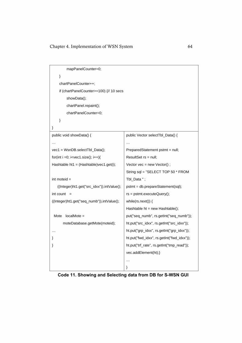
mapPanelCounter=0;
}
chartPanelCounter++;
if (chartPanelCounter>=100) {// 10 secs
showData();
chartPanel.repaint();
chartPanelCounter=0;
}
}
public void showData() {
…
vec1 = WsnDB.selectTbl_Data();
for(int i =0; i<vec1.size(); i++){
Hashtable ht1 = (Hashtable)vec1.get(i);
int moteid =
((Integer)ht1.get("src_idxx")).intValue();
int count =
((Integer)ht1.get("seq_numb")).intValue();
Mote localMote =
moteDatabase.getMote(moteid);
…
}
}
public Vector selectTbl_Data() {
…
PreparedStatement pstmt = null;
ResultSet rs = null;
Vector vec = new Vector() ;
String sql = "SELECT TOP 50 * FROM
Tbl_Data " ;
pstmt = db.prepareStatement(sql);
rs = pstmt.executeQuery();
while(rs.next()) {
Hashtable ht = new Hashtable();
put("seq_numb", rs.getInt("seq_numb"));
ht.put("src_idxx", rs.getInt("src_idxx"));
ht.put("grp_idxx", rs.getInt("grp_idxx"));
ht.put("fwd_idxx", rs.getInt("fwd_idxx"));
ht.put("trf_rate", rs.getInt("tmp_read"));
vec.addElement(ht);}
…
}
Code 11. Showing and Selecting data from DB for S-WSN GUI
Chapter 4. Implementation of WSN System 64

Code 11 describes how to read, bring and show data from the database. Run() method in Scout class is the thread that does a loop, sleeping and incrementing a counter with a defined frequency. It calls showData() to read data in the database through selectTbl_Data() method of WsnDB class. Subsequently, it repaints the map panel and the chart panel with the data put in hashtable as a vector type. Lastly, it is necessary that some files related to Java web start are set up to launch S-WSN GUI on the web. All class files and images of S-WSN GUI were bound as wsnclient.jar and then it was signed with keytool and jarsigner command because of security and sharing environment. The wsnclient.jnlp contains explanation of this application and how to deploy this application. Note that it is made by XML. After starting Apache Tomcat (web server) and click the link to call wsnclient.jnlp in the HTML page, “Java Starting” appears and S-WSN GUI application is started if JRE is already installed on the web browser. Figure 25 shows that S-WSN GUI operates on the internet in the real.
Figure 25. Launching application on the web browser
Chapter 4. Implementation of WSN System 65

Chapter 5
Conclusion
5.1 Conclusion of the work In ubiquitous computing, the context of a user is continuous and dynamic. Using sensors, the context is captured and a user enables to gain the effective use of implicitly sensed context [23]. This research illustrates how to design WSN GUI application as an interactive system to communicate more efficiently between the system and the human. Furthermore, it illustrates how to develop WSN system in order to use more widely in the real world. The process of an interactive system design applying AT helps to make more attractive and graphical UI. AT provided a conceptual framework of designing WSN GUI application. Personas in the process let it know which functions users of this application need. Sketching allowed us to quickly and approximately specify a design of WSN system. The prototyping provided simulation of WSN GUI application to evaluate it through the slide show of MS-PowerPoint. All buttons, link and moving page in MS-PowerPoint actually run for simulation to check and test the basic interface like a real system. It also guided to implement WSN GUI application. The raw data obtained from WSNs
Chapter 5. Conclusion 66

were converted into visual data through WSN GUI application. It was implemented with Java Swing on TinyOS for visual UI of screens and functions. WSN system was build up by three versions of WSN GUI applications. On the web, it was implemented to monitor context status and store the context information anywhere
5.2 Future work WSN GUI application shows the behavior of the network via a wireless communication and an internet. The future work includes developing WSN GUI application for handheld devices like PDA or mobile phone to improve WSN system. Furthermore, Short message services (SMS) API that allows any application to send and receive text messages can be supplemented in WSN GUI application. Administrator can get SMS from WNS GUI application on an emergency situation. WSN system can be utilized for special applications of WSNs. The application having effective Query Processor of sensor network database help to minimize energy consumption of each sensor node and maximize accuracy and rapidity of results about queries.
Chapter 5. Conclusion 67

References
[1] F. Adelstein, G. Richard, L. Schwiebert, and S. Gupta"Fundamental of mobile and pervasive computing: Emphasizing Embeded Wireless Sensor Networking, Ubiquitous Computing, and Middleware," McGraw-Hill, 2004. [2] Kemal Akkaya, Mohamed F. Younis, "A survey on routing protocols for wireless sensor networks," Ad Hoc Networks 3(3):325-349, 2005. [3] Piergiuseppe Di Marco, "Protocol design and implementation for wireless sensor networks," MSc Thesis, KTH Stockholm, 2008 [4] Antti Oulasvirta, Esko Kurvinen, and Tomi Kankainen, "Understanding contexts by being there: case studies in bodystorming", Source Personal and Ubiquitous Computing archive ISSN:1617-4909 Pages: 125-134, 2003. [5] A. Cooper, and R. Reimann, "Modeling users:Personas and goals”, In About Face 2 : the essentials of interaction design," Chapter 5. Wiley Publishing inc. p. 55-74, 2003. [6] Mark D Gross, Ellen-Yi-Luen Do, "Sketching Human computer Interactions," CHI2006 Conference Workshop of Sketching Nurturing Creativity:commonalities in Art, Design, Engineering and Research, 2006. [7] K. Nakakoji, Y. Yamamoto, S. Takada, and B. N. Reeves, "Two-dimensional spatial positioning as a means for reflection in design," Symposium on Designing Interactive Systems 2000, ACM
References 68

Press(2000)145-154, 2000. [8] J. Preece, "Human-Computer Interaction," Extract-Chapter 22: Envisioning Design p.451-465; Extract-Chapter 27: Prototyping p.537-565, Addison-Wesley Publishing Company, Inc., Reading, MA, 1994. [9] J. Rudd, K. Stern, and S. Isensee, "Low vs. high fidelity prototyping debate",Interactions 3(1), p.76-85, ACM Press, 1996. [10] David H. Jonassen, "Revisiting activity theory as a framework for designing student-centered learning environments," In D.H. Jonassen, & S.M. Land(Eds.), Theoritical foundations of learning environments PP.89-121, 2000. [11] Rodriguez, H., "Activity theory and cognitive sciences," 1998 [online].available:http://www.nada.kth.se/henrry/papers/ActivityTheory.html [12] Z. Gregory Bedny, H. Mark Seglin, and David Meister, "Activity theory: history, research and application," TheorETICAL Issues In ErgonOMICS sCIENCE, vol. 1, no. 2, 2000. [13] J. A Stankovic, "Wireless Sensor Networks for In-Home Health-care: Potential and Challenges", in High Confidence Medical Device Software and Systems (HCMDSS) Workshop, Philadelphia, PA, June 2-3, 2005. [14] Tmote Sky Data Sheet, Moteiv, Sanfrancisco, CA, 2006. [Online]. Available:http://www.moteiv.com/products/docs/tmote-sky-datasheet.pdf [15] Pangun Park, "Protocol design of sensor networks for wireless automation", MSc Thesis, KTH Stockholm, 2007. [16] B. Bougard, F. Catthor, D.C. Daly, A. Chandrakasan, W. Dehaene, "Energy Efficiency of the IEEE 802.15.4 Standard in Dense Wireless Microsensor Networks:Modeling and Improvement Perspectives," IMEC, Leuven, Belgium, March 2005. [17] D. Gay, P. Levis, and D. Culler, "Software design patterns for
References 69
tinyos," in Proc LCTES '05, vol. 31, no. 15. New York, NY, USA: ACM Press, 2005, pp.40-49, 2005. [18] Robert Eckstein, Marc Loy,and Dave Wood, "Java Swing," O'Reilly, 1998. [19] Josh Fletcher, "AWT vs Swing, Abstract:A brief comparison of Swing and the AWT when used for GUI developement," 2008, [Online]. Available; http://dn.codegear.com/article/26970. [20] JavaTM Web Start, Sun, 2004, [Online].Available; http://java.sun.com/javase/6/docs/technotes/guides/javaws/ [21] Java Web Start Guide, Overview: Java Web Start Technology, Sun, [Online].Available;http://java.sun.com/javase/6/docs/technotes/guides/javaws/developersguide/overview.html#jws [22] The tinyos community forum. UC Berkeley, 2004 [online]. Available: http://www.tinyos.net [23] K. Anind Dey and D. Gregory Abowd, "Towards a better understanding of context and context awareness," 1st International Symposium on Handheld and Ubiquitous Computing (HUC '99), June 1999. [24] Sajid Hussain, Nick Schofield, W. Abdul Matin, "Design of a Web-Based Application for Wireless Sensor Networks," dexa, pp. 319-326, 17th International Conference on Database and Expert Systems Applications (DEXA'06), 2006. [25] D. Estrin, D. Culler, K. Pister, and G. Sukhatme, "Connecting the physical world with pervasive networks," IEEE Pervaisive Computing, PP.59-69, 2002. [26] D. Estrin, R. Govindan, J. Heidemann, and S. Kumar, "Next century challenges: Scalble coordination in sensor networks,", In Proceedings of the International Conference on Mobile Computing and Networks(Mobicom), 1999. [27] Barton Friedland, "Applying Activity Theory In the Design of
References 70
Usable Software:How Poersonal Beliefs Shape the Use of Tools," MSc Thesis, Mills College, 2006. [28] Ramesh Govindan, "Data-Centric Routing and Storage in Sensor Networks," in Wireless Sensor Networks, Eds. Raghavendra, C.S.,Sivalingnam, K,M., and Znati, t., Kluwer Academic Publisher, chpather 9. pp. 185-205. 2004 [29] B. A. Nardi, "Context and consciousness:activity theory and human-computer interaction," MIT Press, Cambridge, Mass., 1966. [30] D. Culler, D. Estrin, and M. Srivastava, "Overview of sensor networks,"IEEE Computer, vol.37, no.8, pp.41-49, 2004. [31] K. Kuutti, "Activity Theory as a potential framework for human-computer interaction research,” In Nardi, B. (ed), Context and Consciousness:Activity Theory and Human Computer Interaction, Cambridge: MIT Press, 17-44, 1996. [32] Apache Tomcat, The Apache Software Foundation [Online]. Available; http://tomcat.apache.org [33] J. N. Al-Karari, A. E. Kamal, "Routing Techniques in Wireless Sensor Networks; A Survey", IEEE Wireless Communications, December 2004. [34] UCD School of Computer Science and Informatics, Octopus: A Dashboard for Sensor Networks Visual Control [Online]. Available; http://www.csi.ucd.ie/content/octopus-dashboard-sensor-networks-visual-control [35] UCD School of Computer Science and Informatics, Octopus::Developer Documentation [Online]. Available; http://www.csi.ucd.ie/files/Developer%20Documentation.pdf [36] Luna-Vazquez Israel, “Implementation and simulation of routing protocols for wireless sensor networks,” MSc Thesis, universität Siegen, 2006. [37] P. Levis, S. Madden, J. Polastre, R. Szewczyk, K. Whitehouse, A.
References 71

Woo, D. Gay, J. Hill, M. Welsh, E. Brewer , and D. Culler, “TinyOS: An Operating System for Sensor Networks,” from Ambient Intelligence , W. Weber, J. Rabaey, and E. Aarts (Eds.), Spring-Verlag, 2004. [38] C. Intanagonwiwat, R. Govindan, D. Estrin., “Directed diffusion: a scalable and robust communication paradigm for sensor networks,” In Proceeding og the 6th annual interactional conference on Mobile computing and networking, pages 56-67, August 2000 [39] C. Intanagonwiwat, R. Govindan, D. Estrin, J. Heidemann, F. Silva, “Directed diffusion for wireless sensor networking,” IEEE/ACM Transactions on NetworkingIEEE/ACM Transactions on Networking, February 2003 [40] I. F. Akyildiz, W. Su, Y. Sankarasubramaniam, E. Cayirci, “Wireless sensor networks: a survey,” Computer Networks: The International Journal of Computer and Telecommunications Networking, V.38 n.4, p.393-422, March 2002. [41] A. Sangiovanni-Vincentelli, M. Sgroi, A. Wolisz, J. M. Rabaey, “A serviced-based iniveral application interface for ad-hoc wireless sensor networks,” Whitepaper, U.C.Berkeley, 2004. [42] Yongwoo Park, “Eclipse SWT for development of rich clients”, Seongandang, 2007.
References 72

Appendix A
Tbl_Data Table Design
● Query of creating table CREATE TABLE [dbo].[Tbl_Data]( [seq_indx] [int] IDENTITY(1,1) NOT NULL, [seq_numb] [int] NULL, [src_idxx] [nchar](10) NULL, [grp_idxx] [nchar](10) NULL, [fwd_idxx] [nchar](10) NULL, [tmp_read] [nchar](10) NULL, [hum_read] [nchar](10) NULL, [tim_date] [datetime] NULL, CONSTRAINT [PK_Tbl_Data] PRIMARY KEY CLUSTERED ( [seq_indx] ASC )
Appendix 73

● Properties Description seq_indx Sequence number created by the database
seq_numb Data Sequence number from the node
src_idxx Software ID of the node
grp_idxx Software ID of the destination node
fwd_idxx Software ID of the node that forwards the packet
tmp_read Sensed temperature value from the node
hum_read Sensed humidity value from the node
tim_date Time-stamp of inserting each data.
Appendix 74