graphique 1 - richardson rfpd - home€¦ · · 2009-08-07bnc 10-3 the bnc connector, the most...
TRANSCRIPT


10-2
BNC
PAGE
Introduction .............................................................................................................. 3General .................................................................................................................... 4Finder guide...........................................................................................................5-6
BNC 50 ΩInterface ................................................................................................................... 7Characteristics.....................................................................................................8-10Straight plugs.......................................................................................................... 11Right-angle plugs ................................................................................................... 12Straight jacks .......................................................................................................... 13Flange jacks .......................................................................................................... 14Bulkhead jacks ..................................................................................................... 15Flange receptacles ................................................................................................ 16Bulkhead receptacles ............................................................................................ 17Panel receptacles .................................................................................................. 18PCB receptacles .................................................................................................... 19In series adapters .............................................................................................20-21Caps ....................................................................................................................... 22
BNC 75 ΩCharacteristics...................................................................................................23-24Straight plugs.......................................................................................................... 25Right-angle plugs ................................................................................................... 26Jacks ...................................................................................................................... 27Bulkhead jacks ...................................................................................................... 28Panel receptacles .................................................................................................. 29PCB receptacles .................................................................................................... 30In series adapters .............................................................................................30-31Additional connectors ........................................................................................32-33Panel drilling ......................................................................................................34-35Assembly instructions .......................................................................................36-50
CONTENTS

BNC
10-3
The BNC connector, the most popular coaxial connector series in the world, features a two-pin bayonet coupling systemfor quick and reliable engagement and disengagement.
• Wide range : RADIALL's BNC connectors are available with two characteristic impedances 50 Ω and 75 Ω; and, they are completelyintermateable with one another.The BNC range offers cable connectors for both flexible or semi-rigid cables, panel and PCB mount receptacles includingpress mount, through hole and press fit pins connectors. In series adapters and between series adapters includingPUSH-ON type are also available (please look at adapters section).RADIALL also offers you a low cost range called commercial BNC, whose characteristics are compared to those of thestandard BNC in the chart here under.
• Convenient 3-piece design : A range of crimp type cable connectors (straight and right angle models) features :a 3 piece design : single piece body + center contact + outer ferrule,You can find them with the "single piece body" mention on note.
• Fast and reliable cable attachmentThe cable connectors can be either fully crimped or soldered/crimped, offering full flexibility for high volume productionwith standard manual or pneumatic tooling : fast and reliable.
♦ the center contact can be either crimped or soldered,♦ the outer contact is attached to the cable by crimping a ferrule.
Radiall also offers a complete range of MICROWAVE COMPONENTS : terminations, attenuators, etc. designed aroundthe BNC interface.
For further details, please ask for our :
- Between series adapters see adapters section.
Standard BNC Commercial BNC
Applications
♦ Military Telecommunications♦ Civil Telecommunications♦ Measurement and instrumentation♦ General electronics
♦ Civil Telecommunications♦ Datacommunications♦ Measurement and instrumentation♦ Broadcast application♦ Security & video systems♦ Antennas♦ Automotive industry♦ General electronics
Impedance 50 Ω 75 Ω 50 Ω 75 Ω
Codification R141 XXX XXX R142 XXX XXX R141 XXX 161 R142 XXX 161Frequency range DC - 4 GHz DC - 1 GHz DC - 1.5 GHzTemperature range - 65°C / + 165°C -35°C / + 70°CDurability 500 matings 100 matingsCoupling nut Cross knurl Straight knurlMaterial
Coupling nutInsulatorFemale center contact
BrassPTFEBeryllium copper
Die cast zincPolypropylenBrass
INTRODUCTION

10-4
BNC
GENERAL
• Worlwide standardised coaxial connectors
• Bayonet coupling
• Proven strength and reliability
• Good RF performance
• 2 ranges : BNC 50 ΩBNC 75 Ω
• Commercial BNC
• Safety BNC (please consult RADIALL)
APPLICABLE STANDARDS
• MIL-C-39012 / MIL STD 348-A/301
• IEC 169-8
• CECC 22120
• NF-C-93564 KBN series
• UTE-C-93564
APPLICATIONS
• Civil and military radio-telecommunication equipment
• Test and measurement
• Videocommunication
• Computer network
• Industrial network
• General electronics
50 Ω DC - 4 GHzDC - 1.5 GHz (commercial)
75 Ω DC - 1 GHzDC - 1.5 GHz (commercial)
GENERAL

BNC
10-5
CABLE CONNECTORS
CAPS
Model Straight plug Right-angle plug Straight jack Square flange straight jack Bulkhead straight jack
Cable Crimp andfull crimp Clamp Crimp and
full crimp Clamp Crimp andfull crimp Clamp Crimp and
full crimp Clamp Crimp andfull crimp Clamp
2/50/S(RG 178)
R141 003 000(page 11)
R141 253 000(page 14)
R141 301 000(page 15)
R141 323 000(page 15)
2.6/50/S(RG 316)
R141 075 000R141 075 161
(page 11)
R141 004 000(page 11)
R141 181 161(page 12)
R141 154 000(page 12)
R141 217 000(page 13)
R141 290 200(page 14)
R141 254 000R141 277 000R141 278 000
(page 14)
R141 306 000R141 306 503R141 331 500
(page 15)
R141 304 000R141 324 000
(page 15)
2.6/50/D(RD 316)
R141 004 000(page 11)
R141 154 000(page 12)
R141 254 000R141 277 000R141 278 000
(page 14)
R141 304 000R141 324 000
(page 15)
2.6/75/SR142 076 000R142 076 161
(page 25)
R142 004 000(page 25)
R142 154 000(page 26)
R142 217 000(page 27)
R142 202 000(page 27)
R142 306 500R142 306 503R142 306 520R142 331 011
(page 28)
3.8/93/S R142 078 161(page 25)
5/50/S(RG 58)
R141 072 000R141 082 000R141 082 161
(page 11)
R141 007 161R141 009 000R141 010 000
(page 11)
R141 182 161(page 12)
R141 156 000(page 12)
R141 237 000R141 237 161
(page 13)
R141 207 000R141 208 000
(page 12)
R141 292 000(page 14)
R141 256 000R141 258 000R141 259 000
(page 14)
R141 308 000R141 332 500R141 332 161
(page 15)
R141 327 000(page 15)
5/50/D(RG 142)
R141 083 000(page 11)
R141 007 161R141 009 000R141 010 000
(page 11)
R141 182 000R141 183 000
(page 12)
R141 156 000(page 12)
R141 220 000(page 13)
R141 207 000R141 208 000
(page 13)
R141 297 000(page 14)
R141 256 000R141 258 000R141 259 000
(page 14)
R141 327 000(page 15)
5/75/D R142 083 000(page 25)
6/75/S(RG 59)
R142 085 000R142 085 161
(page 25)
R142 016 000R142 016 161
(page 25)
R142 184 000R142 184 161
(page 26)
R142 157 000(page 26)
R142 242 000R142 242 161
(page 27)
R142 295 000R142 295 161
(page 27)
R142 268 000(page 27)
R142 334 161(page 28)
R142 329 000(page 28)
8/75/S R142 017 000(page 25)
10 + 11/50 R141 018 000(page 11)
10 + 11/75 R142 095 000(page 25)
R142 018 000(page 25)
.141“(RG 402)
R141 052 000(page 11)
Model Free Cord Chain Short- circuit chain
M R141 802 000(page 22)
R141 805 000(page 22)
R141 812 000(page 22)
R141 862 000(page 22)
F R141 842 000(page 22)
FINDER GUIDE
ATTENTION ! This guide is intended as an information and does not include all BNC SERIES P/N

10-6
BNC
RECEPTACLES
IN-SERIES ADAPTERS
Model Straight female flange Right-angle female flange
Straight femalebulkhead
Straight male flange
Straight malebulkhead
Press mount receptacle PCB receptacles
Cable Square 2 hole Square Front mount Right angle Square Front mount Straight Straight Right angle Bulkhead right angle
Solder contact with
solder pot
R141 403 000R141 403 500R141 404 000R141 406 000R141 407 000
(page 16)R142 407 000R142 412 000
(page 29)
R141 453 000(page 16)
R141 653 000R141 654 000
(page 16)
R141 554 000R141 557 000R141 559 000R141 572 000R141 574 000R141 6xx 000R141 563 161R141 554 161R141 574 161
(page 17)R142 562 000R142 562 290
(page 29)
R141 680 000(page 17)
R141 440 000(page 18)
R141 580 000(page 18)
R142 580 000(page 29)
Soldercylindrical
contact
R141 500 200(page 18)
Solder pins (standard space)
R141 426 000R141 426 161R141 426 165
(page 19)R142 426 030R142 426 161
(page 30)
R141 665 000R141 665 030R141 665 161
(page 19)
R141 676 423R141 676 433
(page 19)
Solder pins (reduced space)
R141 508 200(page 19)
Press fit pins R141 416 000(page 19)
R141 684 130(page 19)
Model Straight Straight bulkhead Straight flange Right-angle Tee Cross
M - MR141 703 000
(page 20)R142 703 000
(page 30)
F - FR141 704 000
(page 20)R142 704 000
(page 30)
R141 720 000R141 723 000R141 730 000R141 753 000R141 720 161R141 723 161
(page 20)R142 720 161R142 720 000R142 723 000
(page 30)
R141 710 000R141 717 000
(page 20)R142 710 000
(page 30)
M - FR141 770 000
(page 20)R142 770 000
(page 30)
F - F / M
R141 780 000R141 789 000
(page 21)R142 780 000R142 789 000
(page 31)
F - F / FR141 782 000
(page 21)R142 782 000
(page 31)
M - F - F / F R141 799 000(page 21)
FINDER GUIDE
ATTENTION ! This guide is intended as an information and does not include all BNC SERIES P/N

BNC
10-7
LETTERmm inch
LETTERmm inch
min. max. min. max. min. max. min. max.A DIA 10.97 11.07 .432 .436 A DIA 9.78 9.91 .385 .390
B DIA 9.60 9.70 .378 .382 B DIA 4.83 - .190 -
C DIA 8.79 9.04 .346 .356 C 0.15 - .006 -
D DIA 8.31 8.46 .327 .333 D 5.28 5.79 .208 .228
E DIA 8.10 8.15 .319 .321 E 5.33 5.84 .210 .230
F DIA - 4.72 - .186 F 1.98 - .078 -
G 8.31 8.51 .327 .335 G DIA 1.32 1.37 .052 .054
H 1.91 2.06 .075 .081 H DIA 2.31 2.46 .091 .097
J 4.72 5.23 .186 .206
K 4.78 5.28 .188 .208
L 5.18 5.28 .204 .208
M 4.95 - .195 -
PLUGJACK
INTERFACE50 Ω
10-8
BNC
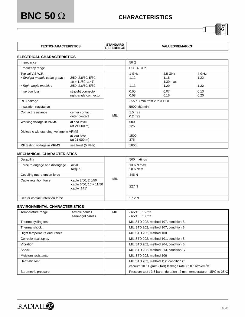
ELECTRICAL CHARACTERISTICS
MECHANICAL CHARACTERISTICS
ENVIRONMENTAL CHARACTERISTICS
TEST/CHARACTERISTICS STANDARDREFERENCE VALUES/REMARKS
Impedance 50 Ω
Frequency range DC - 4 GHz
Typical V.S.W.R. • Straight models cable group :
• Right angle models :
2/50, 2.6/50, 5/50, 10 + 11/50, .141”2/50, 2.6/50, 5/50
1 GHz1.12
1.13
2.5 GHz1.181.30 max1.20
4 GHz1.22
1.22
Insertion loss straight connectorright-angle connector
MIL
0.050.08
0.070.16
0.130.20
RF Leakage - 55 dB min from 2 to 3 GHz
Insulation resistance 5000 MΩ min
Contact resistance center contactouter contact
1.5 mΩ0.2 mΩ
Working voltage in VRMS at sea level (at 21 000 m)
500125
Dielectric withstanding voltage in VRMSat sea level(at 21 000 m)
1500375
RF testing voltage in VRMS sea level (5 MHz) 1000
Durability
MIL
500 matings
Force to engage and disengage axialtorque
13.6 N max28.6 Ncm
Coupling nut retention force 445 N
Cable retention force cable 2/50, 2.6/50cable 5/50, 10 + 11/50cable .141” 227 N
Center contact retention force 27.2 N
Temperature range flexible cablessemi-rigid cables
MIL - 65°C + 165°C- 65°C + 105°C
Thermo cycling test MIL STD 202, method 107, condition B
Thermal shock MIL STD 202, method 107, condition B
Hight temperature endurance MIL STD 202, method 108
Corrosion salt spray MIL STD 202, method 101, condition B
Vibration MIL STD 202, method 204, condition B
Shock MIL STD 202, method 213, condition G
Moisture resistance MIL STD 202, method 106
Hermetic test MIL STD 202, method 112, condition Cvacuum 10-6 Hgmm (Torr) leakage rate < 10-6 atm/cm3/s
Barometric pressure Pressure test : 3.5 bars ; duration : 2 mn ; temperature : 15°C to 25°C
50 Ω CHARACTERISTICS

BNC
10-9
MATERIALS
PLATINGS
POWER RATING
TEST/CHARACTERISTICS STANDARDREFERENCE VALUES/REMARKS
Bodies Brass
Center contact malefemale
BrassBronze or heat treated beryllium following QQ-C-530
Nut Brass
Insulator PTFE
Gasket Silicon rubber
Bodies Nickel
Center contacts Gold
CHARACTERISTICS50 Ω
All dimensions are given in mm.Standard packaging = 100 pieces. For unit packaging add «W» after the P/N

10-10
BNC
COMMERCIAL VERSION R141 XXX 161
ELECTRICAL CHARACTERISTICS
MECHANICAL CHARACTERISTICS
ENVIRONMENTAL CHARACTERISTICS
MATERIALS
PLATINGS
TEST/CHARACTERISTICS VALUES/REMARKS
Impedance 50 Ω
Operating frequency DC to 1.5 GHz
V.S.W.R. typical (1.5 GHz)• Straight models
• Right angle models
2.6565 & 6
1.211.141.051.17
Testing voltage (V.R.M.S) 1500
Operating voltage (V R.M.S) 500
Insulation resistance (MΩ) 5000
Contact resistance (mΩ) 10
Durability 100 mating
Temperature range -35°C + 70°C
Male and female bodies Brass
Coupling nut (straight knurl) Die cast zinc
Outer contact Brass
Insulators Polypropylene
Male and female center contacts Brass
Bodies Nickel
Center contact Gold
∅∅∅∅ ∅
50 Ω CHARACTERISTICS
All dimensions are given in mm.Standard packaging = 100 pieces. For unit packaging add «W» after the P/N

BNC
10-11
STRAIGHT PLUGS CLAMP TYPE FOR FLEXIBLE CABLES
STRAIGHT PLUGS FULL CRIMP TYPE FOR FLEXIBLE CABLES
Cable group Part number Fig.Dimensions (mm) Captive center
contact Assembly instructions NoteA B C
2/50/S+D R141 003 0001 27
2.20.6 yes M02
2.6/50/S+D R141 004 000 3.1
5/50/S+D
R141 007 161 2 no M03 Commercial version
R141 009 0001 28 5.6
1.2 no
M01R141 010 000 1.05yes
10+11/50/S+D R141 018 000 3
.141” R141 052 000 1 29 3.65 1.2 no M09 Semi-rigid cable
Cable group Part number Fig.Dimensions (mm) Captive center
contact Assembly instructions NoteA B C
2.6/50/SR141 075 000 1 31
1.8 0.6
yes
M05R141 075 161 2 30.3 Commercial version
5/50/S
R141 072 000 3 39
3.1 1.05
M08
R141 082 000 4
28 M06
Single piece body
R141 082 161 2 Commercial version
5/50/D R141 083 000 4 3 1.05 Single piece body
Fig. 1 Fig. 3Fig. 2
Fig. 1 Fig. 2
Fig. 3 Fig. 4
50 Ω
For others types of cables (75Ω, 93Ω or BT cables), please see "additional connectors" on page 32-33.
STRAIGHT PLUGS

10-12
BNC
RIGHT ANGLE PLUGS CLAMP TYPE FOR FLEXIBLE CABLES
RIGHT ANGLE PLUGS FULL CRIMP TYPE FOR FLEXIBLE CABLES
Cable group Part number Fig.Dimensions (mm) Captive center
contact Assembly instructions NoteA B
2.6/50/S+D R141 154 000 1 3.1 0.6yes
M02
5/50/S+D R141 156 000 2 5.6 1.05 M01 Unit packaging
Cable group Part number Fig.Dimensions (mm) Captive center
contact Assembly instructions NoteB C
2.6/50/S R141 181 161 1 3.25 1.7
yes
M10 Commercial version
5/50/D R141 182 000 25.5
1.05 M06 Single piece body
5/50/S R141 182 161 1 3.15 M10 Commercial version
5/50/D R141 183 000 2 5.8 1.05 M06 Single piece body
Fig. 1 Fig. 2
Fig. 1 Fig. 2
For others types of cables (75Ω, 93Ω or BT cables), please see "additional connectors" on page 32-33.
RIGHT ANGLE PLUGS50 Ω

BNC
10-13
STRAIGHT JACKS CLAMP TYPE FOR FLEXIBLE CABLES
STRAIGHT JACKS FULL CRIMP TYPE FOR FLEXIBLE CABLES
Cable group Part numberDimensions (mm)
Captive center contact Assembly instructionsA B
5/50/S+DR141 207 000
5.6 1.05no
M01R141 208 000 yes
Cable group Part numberDimensions (mm) Captive center
contact Assembly instructions NoteA B
2.6/50/S R141 217 000 0.57
yes
M05
5/50/SR141 237 000
5.5 1.05 M06
Single piece body
R141 237 161 Commercial version
5/50/D R141 220 000 Single piece body
STRAIGHT JACKS50 Ω
For others types of cables (75Ω, 93Ω or BT cables), please see "additional connectors" on page 32-33.

10-14
BNC
STRAIGHT SQUARE FLANGE JACKS CLAMP TYPE FOR FLEXIBLE CABLES
STRAIGHT SQUARE FLANGE JACKS FULL CRIMP TYPE FOR FLEXIBLE CABLES
Cable group Part number Fig.Dimensions (mm) Captive center
contactAssembly
instructionsPaneldrilling Note
A B C D
2/50/S+D R141 253 000
1 29.5
2.2
0.6
3-56-UNF-2B
yes M02P01
2.6/50/S+D
R141 254 0003.1
R141 278 000 2.7
R141 277 000 2 3 2.6 P02 Insulated flange
5/50/S+D
R141 258 0001 30
5.6 1.05
3-56-UNF-2B
noM01 P01 Unit packaging
R141 259 000•2.6
R141 256 000 2 M03 P02 Insulated flange
Cable group Part number Fig. Dimension D (mm)
Captive center contact
Assembly instructions Panel drilling Note
2.6/50/S R141 290 200• 1 M3 x 0.5
yes
M11 P04 Reverse crimping -unit packaging
5/50/S R141 292 000 2 3 x 56 UNEF 2B M06P23
Single piece body
5/50/D R141 297 000 3 M2.5 x 0.45 M07
Fig. 2Fig. 1
Fig. 2Fig. 1 Fig. 3
50 Ω FLANGE JACKS
• Upon requestFor others types of cables (75Ω, 93Ω or BT cables), please see "additional connectors" on page 32-33.
BNC
10-15
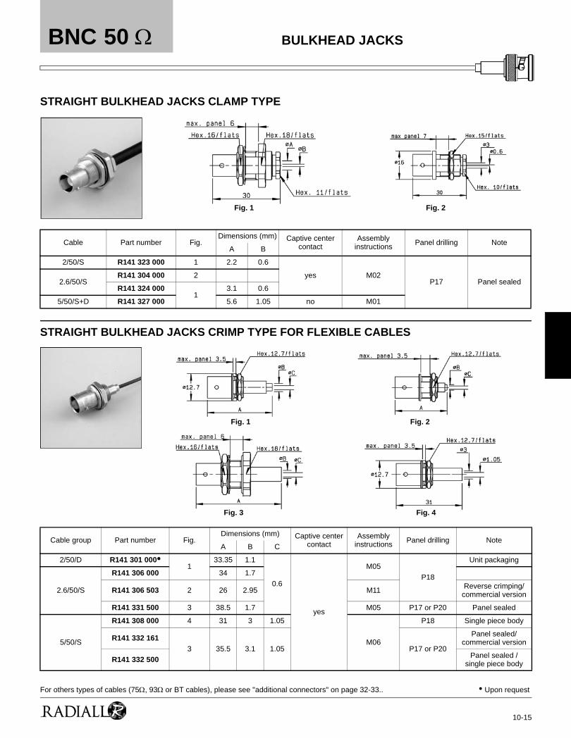
STRAIGHT BULKHEAD JACKS CLAMP TYPE
STRAIGHT BULKHEAD JACKS CRIMP TYPE FOR FLEXIBLE CABLES
Cable Part number Fig.Dimensions (mm) Captive center
contactAssembly
instructions Panel drilling NoteA B
2/50/S R141 323 000 1 2.2 0.6
yes M02P17 Panel sealed2.6/50/S
R141 304 000 2
R141 324 0001
3.1 0.6
5/50/S+D R141 327 000 5.6 1.05 no M01
Cable group Part number Fig.Dimensions (mm) Captive center
contactAssembly
instructions Panel drilling NoteA B C
2/50/D R141 301 000•1
33.35 1.1
0.6
yes
M05P18
Unit packaging
2.6/50/S
R141 306 000 34 1.7
R141 306 503 2 26 2.95 M11 Reverse crimping/commercial version
R141 331 500 3 38.5 1.7 M05 P17 or P20 Panel sealed
5/50/S
R141 308 000 4 31 3 1.05
M06
P18 Single piece body
R141 332 1613 35.5 3.1 1.05 P17 or P20
Panel sealed/commercial version
R141 332 500 Panel sealed /single piece body
Fig. 1 Fig. 2
Fig. 1 Fig. 2
Fig. 3 Fig. 4
50 Ω BULKHEAD JACKS
• Upon requestFor others types of cables (75Ω, 93Ω or BT cables), please see "additional connectors" on page 32-33..

10-16
BNC
FLANGE RECEPTACLES
Part number Fig.Dimensions (mm) Captive center
contact Panel drilling Flange holes NoteA B C
R141 403 000 1
yes
P08 4 x M2.5
R141 403 500• 2 P10 Flange dimensions of N series (1) / unit packaging
R141 404 000 3 P07 4 x M2.5
R141 406 000 1 P084 x 2.6
R141 407 000 3 P07
R141 410 000 4 P02 Insulated flange / solder tag
R141 439 000 5 P13 4 x M2.5 Auxiliary contact
R141 453 000 6 P24 2 hole flange
R141 653 0007
27.6 13.5 19 P05 4 x 3.3 Right angle receptacle
R141 654 000 26.9 12.7 17.5 P06 4 x 2.6 Right angle receptacle
Fig. 1 Fig. 2Fig. 2
Fig.4Fig. 3
Fig. 5 Fig. 6 Fig. 7
50 Ω FLANGE RECEPTACLES
• Upon request(1) Look in the catalog for N series

BNC
10-17
STRAIGHT BULKHEAD RECEPTACLES WITH SOLDER POT
RIGHT ANGLE BULKHEAD RECEPTACLE WITH SOLDER POT
Part number Fig. Captive centercontact Panel drilling Note
R141 554 0001
yes
P16
R141 554 161 P16 Commercial version
R141 557 000 2
P18R141 559 000 3 Solder tag
R141 563 161 2 Silver plated center contact /commercial version
R141 572 000 4 P17Insulated receptacle + solder tag
R141 574 0005
P18
R141 574 161 P18 Commercial version
R141 603 0006 P19
Fully sealed / Q200-5 insulator
R141 605 000 Fully sealed
R141 625 000 7 P18 Hermetically sealed
Part number Captive center contact Panel drilling
R141 680 000 yes P18
Fig. 1 Fig. 2
Fig.4
Fig. 3
Fig. 5 Fig. 6 Fig. 7
50 Ω BULKHEAD RECEPTACLES

10-18
BNC
SCREW ON RECEPTACLE
PRESS MOUNT RECEPTACLE
MALE RECEPTACLES
Part number Captive center contact Panel drilling Note
R141 561 161 yes P22 Commercial version / packaging 500 pieces
Part number Captive center contact Panel drilling
R141 500 200• yes P15
Part number Fig. Captive center contact Panel drilling Note
R141 440 000 1yes
P03
R141 580 000 2 P18 Panel sealed / solder tag
Fig. 1 Fig. 2
50 Ω PANEL RECEPTACLES
• Upon request

BNC
10-19
STRAIGHT PCB FEMALE RECEPTACLES
RIGHT ANGLE PCB FEMALE RECEPTACLES
Part number Fig. Captive center contact Panel drilling Assembly instructions Note
R141 416 000• 1
yes
P12 M13 Press-fit pins
R141 426 000 2
P09R141 426 161 3 Die casted body / commercial version
R141 426 165 4 Tin lead legs / commercial version
R141 508 200• 5 P21
Part number Fig. Captive center contact Panel drilling Assembly
instructions Finish Note
R141 665 000 1
yes
P09Nickel
R141 665 030•2
Tin lead legs
R141 665 161 Die cast body / commercial version
R141 676 423•3 P14 and P17 Gold
Rear mount + washer / unit packaging
R141 676 433• Rear mount + 2 insulated washer / unit packaging
R141 684 130 4 P11 and P20 M12 Nickel Packaging 10 / press-fit pins
Fig. 1 Fig. 4Fig. 3Fig. 2 Fig. 5
Fig. 2Fig. 1
Fig. 3
Fig. 4
50 Ω PCB RECEPTACLES
• Upon request

10-20
BNC
IN SERIES ADAPTERS
Part number Fig. Captive center contact
Dimension A (mm)
Flangeholes
Panel drilling Note
R141 703 000 1
yes
Male - male
R141 704 000 2 Female - female
R141 710 000 3 4 x M2,5 P13 Female - female square flange
R141 717 000 4 4 x 2,6 P02 Female - female square insulated flange
R141 720 000
5
P17Female - female bulkhead
R141 720 161 Female - female bulkhead / commercial version
R141 723 000P17 or P20
Female - female insulated bulkhead
R141 723 161 Female - female insulated bulkhead / commercial version
R141 730 0006
35.7P17
Female - female panel sealed bulkhead
R141 753 000 35.3 Female - female hermetically sealed bulkhead
R141 770 000 7 Male - female right angle
Fig. 1 Fig. 2 Fig. 3
Fig. 4 Fig. 5 Fig. 6 Fig. 7
50 Ω ADAPTERS

BNC
10-21
CROSS AND TEE IN SERIES ADAPTERS
Part number Fig. Captive center contact Note
R141 780 000 1
yes
Male / female-female tee
R141 782 000 2 Female / female-female tee
R141 789 000 3 Female / female-male tee
R141 799 000• 4 Male / female-female-female cross / unit packaging
Fig. 1 Fig. 2
Fig. 3 Fig. 4
50 Ω ADAPTERS
• Upon request
10-22
BNC
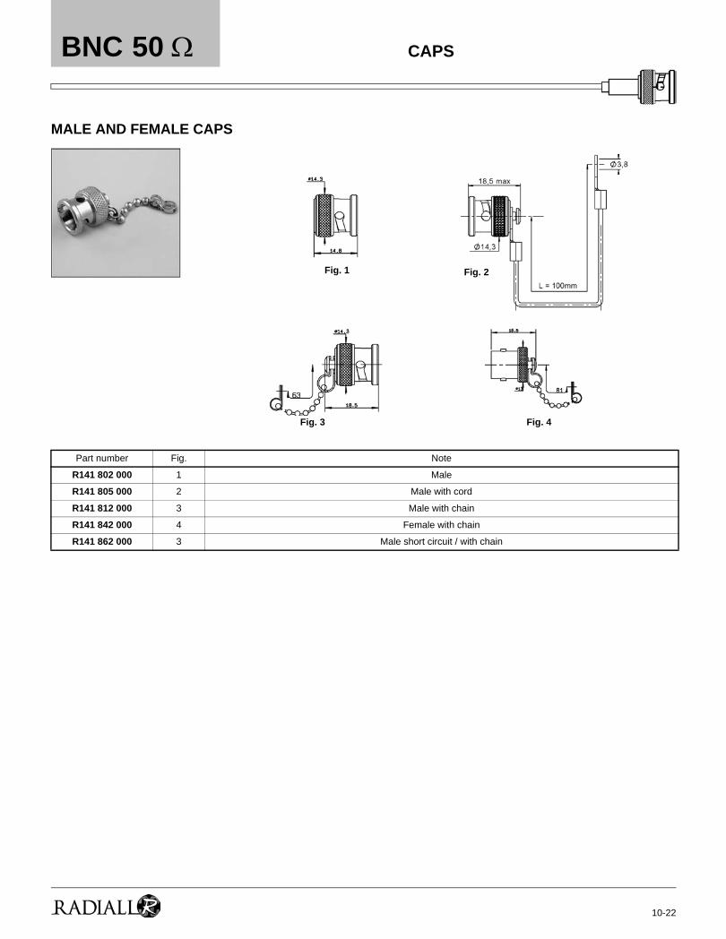
MALE AND FEMALE CAPS
Part number Fig. Note
R141 802 000 1 Male
R141 805 000 2 Male with cord
R141 812 000 3 Male with chain
R141 842 000 4 Female with chain
R141 862 000 3 Male short circuit / with chain
Fig. 1 Fig. 2
Fig. 3 Fig. 4
50 Ω CAPS

BNC
10-23
ELECTRICAL CHARACTERISTICS
MECHANICAL CHARACTERISTICS
ENVIRONMENTAL CHARACTERISTICS
MATERIALS
TEST/CHARACTERISTICS STANDARDREFERENCE VALUES/REMARKS
Impedance 75 Ω
Frequency range DC-1 GHz
V.S.W.R. max • Straight models cable group : 2.6/75, 5/75, 6/75, 8/75,
10 + 11/75• Right angle models : 2.6/75, 6/75
1.30
1.35
Insertion loss straight connectorright-angle connector
MIL
0.2 dB max at 1 GHz0.3 dB max at 1 GHz
RF Leakage - 55 dB min from 2 to 3 GHz
Insulation resistance 5000 MΩ min
Contact resistance center contactouter contact
1.5 mΩ0.2 mΩ
Working voltage in VRMS at sea level(at 21 000m)
500125
Dielectric withstanding voltage in VRMSat sea level(at 21 000m)
1500375
RF testing voltage in VRMS sea level (5 MHz) 1000
Durability
MIL
500 matings
Force to engage and disengage axialTorque
13.6 N max28.6 Ncm
Coupling nut retention force 445 N
Cable retention force cable 2.6/75, 5/75, 6/75, 8/75, 10 + 11/75 340 N
Center contact retention force 27 N
Temperature range flexible cables
MIL
- 65°C + 165°C
Thermo cycling test MIL STD 202, method 107, condition B
Hight temperature endurance MIL STD 202, method 108
Corrosion salt spray MIL STD 202, method 101, condition B
Vibration MIL STD 202, method 204, condition B
Shock MIL STD 202, method 213, condition G
Moisture resistance MIL STD 202, method 106
Hermetic test MIL STD 202, method 112, condition Cvacuum 10-6 Hgmm (Torr) leakage rate <10-6 atm/cm3/s
Barometric pressure Pressure test : 3.5 bars; duration : 2 mn; temperature : 15° C to 25°C
Bodies Brass
Center contact malefemale
BrassBronze or heat treated beryllium following QQ-C-530
Nut Brass
Insulator PTFE
Gasket Silicon rubber
75 Ω CHARACTERISTICS
All dimensions are given in mmStandard packaging = 100 pieces. For unit packaging add «W» after the P/N

10-24
BNC
PLATINGS
COMMERCIAL VERSION R142 XXX 161
ELECTRICAL CHARACTERISTICS
MECHANICAL CHARACTERISTICS
ENVIRONMENTAL CHARACTERISTICS
MATERIALS
PLATINGS
TEST/CHARACTERISTICS VALUES/REMARKS
Bodies Nickel
Center contacts Gold
TEST/CHARACTERISTICS VALUES/REMARKS
Impedance 50 Ω
Operating frequency DC to 1.5 GHz
V.S.W.R. typical (1.5 GHz)• Straight models
• Right angle models
2.6565 & 6
1.211.141.051.17
Testing voltage (V.R.M.S) 1500
Operating voltage (V R.M.S) 500
Insulation resistance (MΩ) 5000
Contact resistance (mΩ) 10
Durability 100 mating
Temperature range -35°C + 70°C
Male and female bodies Brass
Coupling nut (straight knurl) Die cast zinc
Outer contact Brass
Insulators Polypropylene
Male and female center contacts Brass
Bodies Nickel
Center contact Gold
∅∅∅∅ ∅
75 Ω
All dimensions are given in mm.
CHARACTERISTICS
Standard packaging = 100 pieces. For unit packaging add «W» after the P/N

BNC
10-25
STRAIGHT PLUGS CLAMP TYPE FOR FLEXIBLE CABLES
STRAIGHT PLUGS FULL CRIMP TYPE FOR FLEXIBLE CABLES
Cable group Part number Fig.Dimensions (mm) Captive center
contactAssembly
instructions NoteA B C
2.6/75/S R142 004 000 1yes
M04
6/75/SR142 016 000 2 28 6.6 0.75 M01 Unit packaging
R142 016 161 3M03
Commercial version
8/75/S+D R142 017 000 2 45.5 9.1 1.5yes
Unit packaging
10+11/75/S+D R142 018 000 4 M01
Cable group Part number Fig.Dimensions (mm) Captive
center contactAssembly
instructions NoteA B C
2.6/75/SR142 076 000 1
31 1.8 0.4
yes
M05R142 076 161
3 Commercial version3.8/93/S R142 078 161 30 3.85 0.6 M14
5/75/D R142 083 0002
27.3 5.5
0.75M066/75/S
R142 085 000
28
6.6 Single piece body
R142 085 161 3 3.9 Commercial version
10/75/S R142 095 000 2 11.05 1.35 Single piece body
Fig. 1 Fig. 2
Fig. 3 Fig. 4
Fig. 1 Fig. 2 Fig. 3
75 Ω STRAIGHT PLUGS
For others types of cables (75Ω, 93Ω or BT cables), please see "additional connectors" on page 32-33.

10-26
BNC
RIGHT ANGLE PLUGS CLAMP TYPE FOR FLEXIBLE CABLES
RIGHT ANGLE PLUGS FULL CRIMP TYPE FOR FLEXIBLE CABLES
Cable group Part number Fig.Dimensions (mm) Captive center
contact Assembly instructionsA B
2.6/75/S R142 154 000 1 3.1 0.6yes
M02
6/75/S R142 157 000 2 6.6 0.75 M01
Cable group Part number Fig. Captive center contact Assembly instructions Note
6/75/SR142 184 000 1
yesM06
R142 184 161 2 M10 Commercial version
Fig. 1 Fig. 2
Fig. 1 Fig. 2
75 Ω
For others types of cables (75Ω, 93Ω or BT cables), please see "additional connectors" on page 32-33.
RIGHT ANGLE PLUGS

BNC
10-27
STRAIGHT JACKS FULL CRIMP TYPE FOR FLEXIBLE CABLES
STRAIGHT SQUARE FLANGE JACKS CLAMP TYPE FOR FLEXIBLE CABLES
STRAIGHT SQUARE FLANGE JACKS FULL CRIMP TYPE FOR FLEXIBLE CABLES
Cable group Part numberDimensions (mm)
Captive center contact Assembly instructions NoteA B C
2.6/75/S R142 217 000 1.75 0.4 32.5
yes
M05
6/75/SR142 242 000
6.6 0.7529.5
M06Single piece body
R142 242 161 29 Single piece body /commercial version
Cable group Part number Fig. Captive center contact Assembly instructions Panel drilling Note
2.6/75/S R142 202 000 1yes
M04P01 Unit packaging
6/75/S R142 268 000 2 M01
Cable group Part number Captive center contact Assembly instructions Panel drilling Note
6/75/SR142 295 000
yes M06 P01Single piece body / unit packaging
R142 295 161 Single piece body / commercial version
Fig. 1 Fig. 2
75 Ω
For others types of cables (75Ω, 93Ω or BT cables), please see "additional connectors" on page 32-33.
JACKS

10-28
BNC
STRAIGHT BULKHEAD JACKS CLAMP TYPE FOR FLEXIBLE CABLES
STRAIGHT BULKHEAD JACKS CRIMP TYPE FOR FLEXIBLE CABLES
Cable group Part number Captive center contact Assembly instructions Panel drilling Note
6/75/S R142 329 000 yes M01 P17 Panel sealed
Cable group Part number Fig.Dimensions (mm) Captive
center contact
Assembly instructions
Panel drilling Note
A B C
2.6/75/S
R142 306 500
1 26 2.950.4
yes
M11 P18
Reverse crimping - commercial version
R142 306 503Reverse crimping
R142 306 520• 0.6
R142 331 011•2
38 1.75 0.4 M05P17 or P20
Panel sealed / silver plated
6/75/S R142 334 161 35 6.6 0.75 M06 Commercial version
Fig. 1 Fig. 2
75 Ω
• Upon requestFor others types of cables (75Ω, 93Ω or BT cables), please see "additional connectors" on page 32-33.
BULKHEAD JACKS

BNC
10-29
STRAIGHT SQUARE FLANGE RECEPTACLES WITH SOLDER POT
STRAIGHT BULKHEAD RECEPTACLES WITH SOLDER POT
BULKHEAD MALE RECEPTACLE WITH SOLDER POT
Part number Captive center contact Panel drilling Flange holes A Note
R142 407 000yes P07
4 x 2.6
R142 412 000 4 x M2.5 Unit packaging
Part number Fig. Captive center contact Panel drilling Note
R142 562 000 1yes P18
Unit packaging
R142 562 290• 2 With 2 insulated washers + solder tag / Unit packaging
Part number Captive center contact Panel drilling Note
R142 580 000 yes P18 Panel sealed + solder tag / Unit packaging
Fig. 1 Fig. 2
75 Ω
• Upon request
PANEL RECEPTACLES

10-30
BNC
STRAIGHT PCB FEMALE RECEPTACLES
IN SERIES ADAPTERS
Part number Fig. Captive center contact Panel drilling Note
R142 426 030• 1yes P09
R142 426 161 2 Commercial version
Part number Fig. Captive center contact Panel drilling Note
R142 703 000 1
yes
Male - male
R142 704 000 2 Female - female
R142 710 000 3 P01 Female - female square flange
R142 720 000
4
P17 Female - female bulkhead
R142 720 161 P17 Female - female bulkhead /commercial version
R142 723 000 P17 or P20 Female - female insulated bulkhead
R142 770 000 5 Male - female right angle
Fig. 1 Fig. 2
Fig. 3 Fig. 4
Fig. 2Fig. 1
Fig. 5
75 Ω PCB RECEPTACLES & ADAPTERS
• Upon request

BNC
10-31
TEE IN SERIES ADAPTERS
Part number Fig. Captive center contact Note
R142 780 000 1
yes
Male / female-female tee
R142 782 000 2 Female / female-female tee
R142 789 000 3 Female / female-male tee
Fig. 1 Fig. 2
Fig. 3
ADAPTERS75 Ω

10-32
BNC
For more information regarding these connectors, please consult us.
CONNECTORS WITH FLAT GASKET
50 Ω CONNECTORS FOR 75 Ω or 93 Ω CABLE75 Ω Cable
93 Ω Cable
P/N Description Captive center contact
R141 007 000 Straight plug clamp type for 5/50/S+D cable
noR141 011 000 Straight plug clamp type for 6/75/S cable
R141 015 000 Straight plug clamp type for 6/75/S cable
R141 154 000 Right angle plug clamp type for 2.6/50/S+D cable yes
R141 206 000 Straight jack clamp type for 5/50/S+D cable
no
R141 209 000 Straight jack clamp type for 6/75/S cable
R141 256 000 Straight square flange jack clamp type for 5/50/S+D cable
R141 257 000 Straight square flange jack clamp type for 5/50/S cable
R141 261 000 Straight square flange jack clamp type for 6/75/S cable
R141 264 000 Straight insulated square flange jack clamp type for 6/75/S cable
R142 017 000 Straight plug clamp type for 8/75/S+D cable (unit packaging) yes
P/N Description Captive center contact
R141 004 000 Straight plug clamp type for 2.6/75/S cable yes
R141 011 000 Straight plug clamp type for 6/75/S cableno
R141 013 000 Straight plug clamp type for 6/75/S cable
R141 014 000 Straight plug clamp type for 6/75/S cable yes
R141 015 000 Straight plug clamp type for 6/75/S cable no
R141 074 000 Straight plug clamp type for 6/75/S cable
yesR141 082 280 Straight plug crimp type for PH18 cable (unit packaging)
R141 154 000 Right angle plug clamp type for 2.6/75/D cable
R141 209 000 Straight jack clamp type for 6/75/S cable no
R141 210 000 Straight jack clamp type for 6/75/S cableyes
R141 254 000 Straight square flange jack clamp type for 2.6/75/S cable
R141 261 000 Straight square flange jack clamp type for 6/75/S cableno
R141 264 000 Straight insulated square flange jack clamp type for 6/75/S cable
R141 277 000 Straight insulated square flange jack clamp type for 2.6/75/S cable
yes
R141 278 000 Straight square flange jack clamp type for 2.6/75/S cable
R141 329 000 Straight bulkhead jack clamp type for 6/75/S cable
R141 334 161 Straight bulkhead jack crimp type for 6/75/S cable
R141 334 500 Straight bulkhead jack crimp type for 6/75/S cabl (unit packaging)
P/N Description Captive center contact
R141 013 000 Straight plug clamp type for 6/93/S cable no
R141 014 000 Straight plug clamp type for 6/93/S cableyes
R141 077 000 Straight plug crimp type for 3.8/93/S cable
ADDITIONAL CONNECTORS
Standard packaging : 100 pieces
R142R141
BNC 50 Ω BNC 75 Ω

BNC
10-33
75 Ω CONNECTORS FOR 93 Ω CABLE
CONNECTORS FOR BT OR SPECIAL CABLES Look at BT43 catalog
CONNECTORS FOR DIGITAL BROADCAST APPLICATIONS Special finish
Connectors developed for NOKIA 0.6/2.8 AF 75 Ω cable.
P/N Description Packaging
R142 016 000 Straight plug clamp type for 6/93/S cable Unit
R142 085 000 Straight plug crimp type for 6/93/S cable 100 pieces
P/N Description Packaging
R141 005 000 Straight plug clamp type dia 3,5/50, PPD cable100 pieces
R141 015 000 Straight plug clamp type dia 6/75/S, 75PD cable
R141 082 280 Straight plug crimp type for 6/75, PH 18 cableUnit
R142 080 000 Straight plug crimp type for 3,8/75/T, ET 33542 cable
R142 081 100 Straight plug crimp type for 3,6/75/D, P46431 cable 100 pieces
R142 081 120 Straight plug crimp type for BT3002 / TZC 75024 cable Unit
R142 081 130 Straight plug crimp type for BT3002 / TZC 75024 cable 100 pieces
R142 081 320 Straight plug crimp type for BT2001 cable Unit
R142 081 330 Straight plug crimp type for BT2001 cable 100 pieces
R142 083 320 Straight plug crimp type for BT2002 cable Unit
R142 083 330 Straight plug crimp type for BT2002 cable100 pieces
R142 085 230 Straight plug crimp type for BICC T3304 cable
R142 086 320 Straight plug crimp type for BT2003 cable Unit
R142 086 340 Straight plug crimp type for BT2003 cable100 pieces
R142 177 200 Right angle plug crimp type for BT3002 / TZC 75024 cable
R142 177 200W Right angle plug crimp type for BT3002 / TZC 75024 cable Unit
R142 181 200 Right angle plug crimp type for BT2002 cable 100 pieces
R142 181 200W Right angle plug crimp type for BT2002 cable unit
R142 185 200 Right angle plug crimp type for BT2003 cable 100 pieces
R142 185 200W Right angle plug crimp type for BT2003 cable Unit
R142 325 100W Straight bulkhead jack crimp type for BT3002 / TZC 75024 cable 100 pieces
R142 325 106 Straight bulkhead jack crimp type for BT3002 / TZC 75024 cable
P/N Description Packaging Outer contact finish Body finish
R142 082 042 Straight plug crimp type for 5/75/S cable 100 piecesGold
BBR*R142 082 042W Straight plug crimp type for 5/75/S cable unit
R142 082 047 Straight plug crimp type for 5/75/S cable 100 piecesBBR*
R142 082 047W Straight plug crimp type for 5/75/S cable unit
R142 720 023 Female female bulkhead adapter 100 pieces - Gold
ADDITIONAL CONNECTORS
* BBR : Bright Bronze RADIALL.

10-34
BNC
P01 P02 P03
P04 P05 P06
P07 P08 P09
P10 P11 P12
P13 P14 P15
PANEL DRILLING

BNC
10-35
P16 P17 P18
P19 P20 P21
P22 P23 P24
PANEL DRILLING

10-36
BNC
M 01
Part NumberStripping length (mm)
Recommended coupling torquea b e
R141 009 000R141 010 000 4.5 8.5 2.5
450 N.cm
R141 013 000 5.5 6 0.5
R141 156 000R141 208 000R141 258 000R141 259 000R141 327 000R142 016 000R142 157 000R142 268 000R142 329 000
2.5 7 3
R141 018 000R141 207 000R142 018 000
3 9 1
STRIPPING DIMENSIONS
1
2
5
2
- Strip the cable as shown in sketch 1.1
- Slide the back nut over the cable assembly.- Slide the centre contact onto the inner conductor.
4
- Slide the back nut, the washer and the 'V' groove gasket onto the cable.
- Slide the clamp braid sleeve over the braid. - Solder the centre contact onto the inner conductor.
- Fold the braid back and trim off the extra braid.- Trim dielectric back as shown in sketch 2.
36
- Screw sub-assembly into the connector body with the adapted wrench.
- Recommended coupling torque (see table).
ASSEMBLY INSTRUCTIONS

BNC
10-37
M 02
Part NumberStripping length (mm)
Recommended coupling torquea b c
R141 003 000R141 004 000R141 154 000R141 253 000
R141 254 000R141 277 000R141 278 000R141 304 000
R141 323 000R141 324 000
R142 154 0002 3 4 450 N.cm
STRIPPING DIMENSIONS
4
2
- Slide clamp nut onto cable.- Strip the cable.- Cut the jacket (2 slots) appart if necessary.
1- Solder the cable inner conductor into centre
contact.- Slide the back nut over teh clamp assembly.
3
- Slide the clamp braid sleeve between cable dielectric and braid.
- Cut the braid flush with the clamp braid sleeve.- Slide the spacer.
- Mount the gasket into the connector.- Screw sub-assembly into the connector body.
ASSEMBLY INSTRUCTIONS

10-38
BNC
M 03
Part NumberStripping length (mm) Recommended coupling
torquea b e
R141 007 161R141 256 000 2.5
3 7
450 N.cmR142 016 161 7 3
R142 017 000 3 3.5 10
STRIPPING DIMENSIONS
1
2
52
- Strip the cable as shown in sketch 1.1
- Slide the back nut over the cable assembly.4
- Slide the clamp nut, the washer and the gasket onto the cable.
- Slide the clamp braid sleeve over the braid.
- Solder the centre contact onto the inner conductor.
- Fold the braid back and trim off the extra braid.- Trim dielectric back as shown in sketch 2.
3 6- Screw sub-assembly into the connector body with
the adapted wrench.- Recommended coupling torque (see table).
ASSEMBLY INSTRUCTIONS

BNC
10-39
M 04
Part NumberStripping length (mm) Recommended coupling
torquea b c
R142 004 000 4 3 240 N.cm
R142 202 000 3.5 3.5 1
STRIPPING DIMENSIONS
4
2
- Slide clamp nut onto cable.- Strip the cable.- Cut the jacket (2 slots) appart if necessary.
1- Solder the cable inner conductor into centre
contact.- Slide the back nut over the clamp assembly.
3
- Slide the clamp braid sleeve between cable dielectric and braid.
- Cut the braid flush with the clamp braid sleeve.- Slide the spacer.
- Mount the gasket into the connector.- Screw sub-assembly into the connector body.
ASSEMBLY INSTRUCTIONS

10-40
BNC
M 05
Part Number
Stripping length (mm)
Hex.
Ferrule Center contact
a b c eStandard crimp
toolsDies included
MIL standard R282 293 000
(M22520/5-01) + Dies
Standard crimp tools
Dies included
MIL standard R282 293 000
(M22520/5-01) + Dies
R141 075 000R141 217 000R141 301 000R142 076 000R142 076 161R142 217 000
4 10 18.5 14.5
1.73 - 5.4
R282 223 000 R282 235 01(M22520/5-11) R282 223 000
R282 235 011(M22520/5-11)
R141 306 000R141 331 500R142 331 011
1.73 - 6.48 R282 235 013(M22520/5-13)
STRIPPING DIMENSIONS
52
- Slide the ferrule onto the cable.- Strip the cable.
1- Slide cable into body until it bottoms against
insulator.
4
- Fan the braid.- Slide the braid clamp and the insulator between the
dielectric and the braid.- Slide the insulator between the dielectric and the
braid.
- Slide the ferrule over the braid.
- Slide on the centre contact until it bottoms against the cable dielectric.
- Solder or crimp the centre contact with crimping tool (see table).
- Clean solder area if necessary.
3 6- Crimp the ferrule with crimping tool (see table).- Cut the excess of braid if necessary.
ASSEMBLY INSTRUCTIONS

BNC
10-41
M 06
Part number
Stripping length (mm)
Hex.
Ferrule Center contact
a b e Dies included
MIL standardR282 293 000
(M22520/5-01) + Dies
Dies included
MIL standardR282 293 000
(M22520/5-01) + Dies
R141 082 000R141 082 161R141 083 000R141 182 000R141 183 000
R141 292 000R141 308 000R141 332 161R141 332 500
4
11
8.5
1.735.4
R282 223 000
R282 235 011 (M22520/5-11)
R282 223 000
R282 235 011 (M22520/5-11)
R141 220 000R141 237 000 R141 237 161
1.736.48
R142 085 000R142 086 161
R142 184 000 R282 235 013 (M22520/5-13) R282 235 013
(M22520/5-13)R142 242 000 R142 242 161 R282 235 011
(M22520/5-11)
R142 095 000 2.5 9 1.7310.54 R282 231 000 R282 235 116
(Y116 DANIELS)R282 235 011 (M22520/5-11)R142 295 000 R142 295 161
4 8.5R142 083 000 5.4 R282 223 000 R282 235 011
(M22520/5-11)Crimp tool R282 281 000
Positioner R282 968 000 Selection 8
Heatshring sleeve(option)
Centre contactSTRIPPING DIMENSIONS
52
- Slide the heatshrink sleeve onto the cable (Option).- Slide the ferrule onto the cable.- Strip the cable.
1 - Slide the cable into the body until it bottoms against insulator.
4
- Slide the centre contact on until it bottoms against the cable dielectric.
- Crimp the centre contact with crimping tool (see table).
- Slide the ferrule over the braid.- Crimp the ferrule with crimping tool (see table).
- Fan the braid.3
6 - Cut the excess of braid if necessary.- Slide the sleeve over the ferrule and heatshrink it
in place (Option).
ASSEMBLY INSTRUCTIONS

10-42
BNC
M 07
Part number
Stripping length (mm)
Hex.Crimp tools Center contact
Recommended coupling torque
a b Dies included MIL standard R282 293 000(M22520/5-01) + Dies
Crimp tool R282 291 000 +positioner RT282 997 000
R141 297 000 14 9 5.4 R282 223 000 R282 235 011 (M22520/5-11) Selection N°7 170 N.cm
STRIPPING DIMENSIONS
2
- Slide onto cable the ferrule and the heatshrink sleeve.- Strip the cable.
1- Mount the sub-assembly into the main body and
screw the clamp nut.- Slide sleeve over the ferrule and heatshrink it in
place.
3
- Fan the braid- Slide the sleeve over the clamp nut.- Slide the braid on the sub-assembly.- Slide the ferrule over the clamp nut (in direction F).- Crimp the ferrule.- Cut the excess of braid.- Mount the insulator against the sleeve.- Mount center contact against the insulator.- Crimp the center contact.
ASSEMBLY INSTRUCTIONS

BNC
10-43
M 08
Part number
Stripping length (mm)
Hex.
FerruleRecommended coupling
torquea b c e Standard crimp toolsDies included
MIL standardR282 293 000 (M22520/5-01)
+ Dies
R141 072 000 7 8.5 26 19 5.41 R282 223 000 R282 235 011M22520/5-11 450 N.cm
STRIPPING DIMENSIONS
4
2
- Slide the ferrule onto the cable.- Strip the cable.
1- Crimp the ferrule with the crimping tool
R282 223 000 (Hex : 5.41) or R282 293 000 (M22520/5-01) + dies R282 235 011 (M22520/5-11).
- Crimp or solder the center contact.- Put the 0-ring onto the insulator holder.
3
- Fan the braid.- Slide the insulator holder under the braid.- Slide the ferrule onto the cable braid in F direction.
- Screw this assembly into the connector body.Recommended coupling torque (450 N.cm).
ASSEMBLY INSTRUCTIONS

10-44
BNC
M 09
Part number Recommended coupling torque
R141 052 000 400 N.cm
STRIPPING DIMENSIONS
4
2
- Strip the cable.1
- Solder the cable inner conductor into centre contact.
- Solder the braid clamp onto the cable.
3
- Slide the clamp nut, the washer and the «V» groove gasket onto the cable.
- Slide clamp braid sleeve over braid.- Slide braid clamp over the braid.- Trim back dielectric as shown.
- Screw sub-assembly into the connector body.
ASSEMBLY INSTRUCTIONS

BNC
10-45
M 10
Part NumberStripping length (mm)
Hex.Crimp tools
a b e Diesincluded
MIL standard R282 293 000(M22520/5-01) + Dies
R141 181 161 2.5 7.5 14 6.48 R282 223 000 R282 235 013 (M22520/5-13)
R141 182 161 2 6.5 13.5 3.25 R282 211 000 R282 235 003 (M22520/5-03)
R142 184 161 2 7.5 14 5.41 R282 223 000 R282 235 011 (M22520/5-11)
STRIPPING DIMENSIONS
52
- Slide the heatshrink sleeve onto the cable (Option).- Slide the ferrule onto the cable.- Strip the cable.
1- Crimp the ferrule with crimping tool (see table).- Solder the inner conductor.
4
- Fan the braid. - Place the cap into the body.
- Push the connector body under the braid.- Slide the ferrule over the braid.
3 6- Press on the cap flush or slightly below the surface
of the body assembly.- Slide the sleeve over the ferrule and heatshrink it
in place (Option).
ASSEMBLY INSTRUCTIONS

10-46
BNC
M 11
Part number
Stripping length (mm)
Hex.
Center contact Ferrule
a b e f DiesIncluded
MIL standardR282 293 000
(M22520/5-01) + Dies
DiesIncluded
MIL standardR282 293 000
(M22520/5-01) + Dies
R141 290 200
3
8.4 3.4
1.5
1.73-4.5 R282 211 000 R282 235 009 (M22520/5-09) R282 223 000
R282 235 009 (M22520/5-09)
R141 306 503
10 5
R142 306 500 1.73-4.52 R282 223 000 R282 235 011 (M22520/5-11) R282 211 000
R142 306 5031.73-4.5 R282 211 000 R282 235 009
(M22520/5-09) R282 223 000
R282 235 011 (M22520/5-11)
R142 306 520 R282 235 009 (M22520/5-09)
STRIPPING DIMENSIONSInsulator Center contact
BodyFerrule
52
- Strip the cable as shown in sketch 1.- Slide the ferrule until it bottoms against the sleeve.
1- Slide the center contact on until it bottoms against
the insulator back nut.- Solder or crimp the contact with crimping tool (see
table).
4
- Fold the braid back.- Trim off the extra braid as shown in sketch 2.
- Mount the body onto the sub-assembly.
- Trim the inner conductor as shown in sketch 2.- Slide insulator onto cable dielectric.
3 6- Crimp the body with crimping tool (see table).
ASSEMBLY INSTRUCTIONS

BNC
10-47
M 12
Part number
R141 684 130
- Slide the flat tool into the machine (press).1
- Push on the top (about 500 N) until total insertion (in direction F) (push connector body until it bottoms against PCB).
- Remove the connector and the PCB assembly.
2
PC BOARDMATERIAL
GLASS FIBRE EPOXYD NEMA : G10, G11, FR4, FR5, DIN 40802 : EP-GC 01, EP-GC 02
HOLE FOR 1 mm COMPLIANT PIN
ASSEMBLY INSTRUCTIONS
Insertion procedure

10-48
BNC
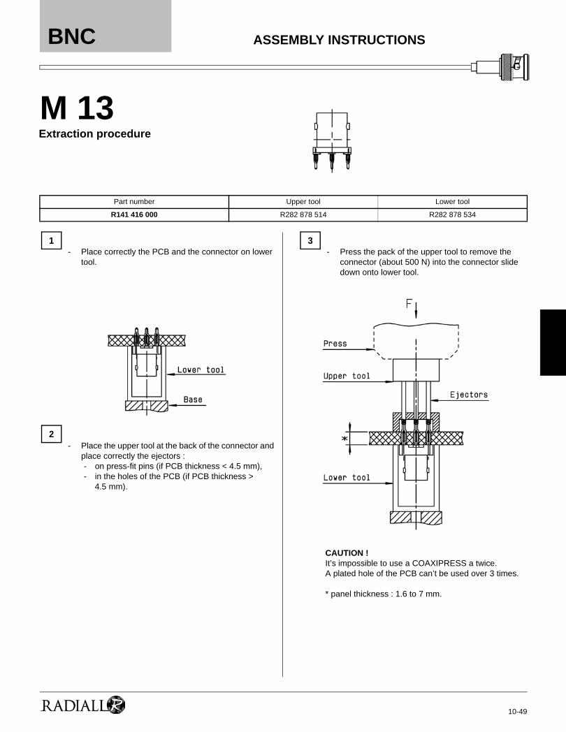
M 13
Part Number Upper tool Lower tool
R141 416 000 R282 878 240 R282 878 524
4
2
- Slide the upper tool (look at upper tool board) into the machine (press) or the flat tool.
1- Place correctly the right angle connector with
press-fit termination on the PCB and introduce the press-fit extremity in the holes of the PCB.
3
- Slide the lower tool into the base and place correctly the PCB on this tool (positionning pins).
- Push o the top (about 500 N) until total insertion (in direction F) (push connector body until it bottoms against PCB).
- Remove the connector and the PCB assembly.
PC BOARDMATERIAL
GLASS FIBRE EPOXYD NEMA : G10, G11, FR4, FR5, DIN 40802 : EP-GC 01, EP-GC 02
HOLE FOR 1 mm COMPLIANT PIN
ASSEMBLY INSTRUCTIONS
Insertion procedure
BNC
10-49
M 13
Part number Upper tool Lower tool
R141 416 000 R282 878 514 R282 878 534
2
- Place correctly the PCB and the connector on lower tool.
1- Press the pack of the upper tool to remove the
connector (about 500 N) into the connector slide down onto lower tool.
3
- Place the upper tool at the back of the connector and place correctly the ejectors :- on press-fit pins (if PCB thickness < 4.5 mm),- in the holes of the PCB (if PCB thickness >
4.5 mm).
CAUTION !It’s impossible to use a COAXIPRESS a twice.A plated hole of the PCB can’t be used over 3 times.
* panel thickness : 1.6 to 7 mm.
ASSEMBLY INSTRUCTIONS
Extraction procedure

10-50
BNC
M 14
Part number
Stripping length (mm)
Hex.
Center contact Ferrule
a b c e DiesIncluded
MIL standardR282 293 000
(M22520/5-01) + Dies
DiesIncluded
MIL standardR282 293 000
(M22520/5-01) + Dies
R142 078 161 4 10.5 17.5 13.5 1.73 - 6.48 R282 223 000 R282 235 011 (M22520/5-11) R282 223 000 R282 235 013
(M22520/5-13)
STRIPPING DIMENSIONS
52
- Slide the ferrule onto the cable.- Strip the cable.
1- Slide cable into body until it bottoms against
insulator.
4
- Fan the braid.- Slide the braid clamp between the dielectric and the
braid.
- Slide the ferrule over the braid.
- Slide on the centre contact until it bottoms against the cable Crimp the centre contact with crimping tool.
3 6- Crimp the ferrule with crimping tool.- Cut the excess of braid if necessary.
ASSEMBLY INSTRUCTIONS