graphite and titanium alloy radiation damage tests aida amroussia, phd candidate 1 pr. carl j...
TRANSCRIPT

Graphite and Titanium Alloy Radiation Damage Tests
Aida Amroussia, PhD Candidate1
Pr. Carl J Boehlert1
Dr. Frederique Pellemoine2
Pr. Wolfgang Mittig2
1Michigan State University2Facility For Rare Isotope Beams

1. Introduction
2. Microstructure characterization
3. Experimental Methods
4. Irradiation damage in Ti-6Al-4V: Literature review
5. Microstructure characterization
6. Hardness measurements
7. Conclusion
Outline
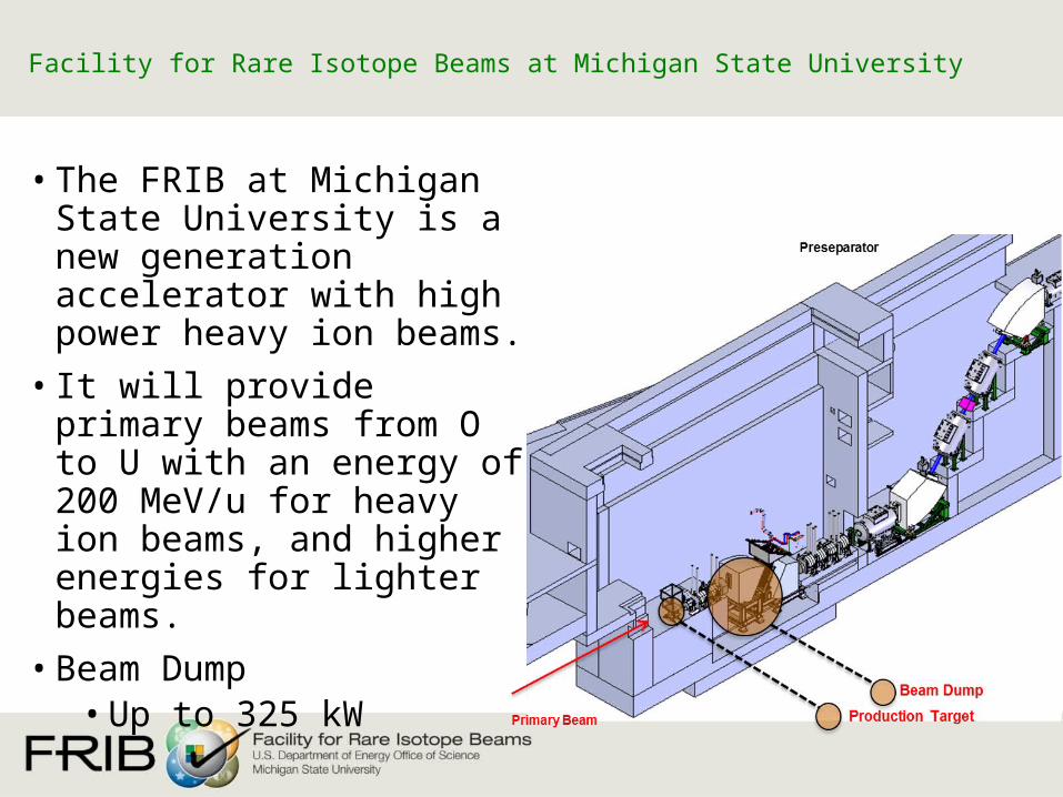
• The FRIB at Michigan State University is a new generation accelerator with high power heavy ion beams.
• It will provide primary beams from O to U with an energy of 200 MeV/u for heavy ion beams, and higher energies for lighter beams.
• Beam Dump• Up to 325 kW
Facility for Rare Isotope Beams at Michigan State University

• Water-filled rotating drum beam dump chosen for FRIB baseline
FRIB Beam Dump
• FRIB conditions:Beam Dump lifetime of 1 year (5500 h) desiredEstimated cumulative dpa after one year of use ~9 dpa with a fluence of
1015 ions.cm-2
Se from 0.08 keV/nm (with O beam) to 12.6 keV/nm (with U beam)
• Ti-6Al-4V and Ti-6Al-4V-1B were chosen as candidate materials• The current study addresses the radiation damage challenge and
focuses on understanding Swift Heavy Ion (SHI) effects on Ti-alloy that can limit beam dump lifetime

• Two main irradiation experiments with Ti-6Al-4V and Ti-6Al-4V-1B samples were performed at the IRRSUD beamline facility at the GANIL-CIMAP Laboratory, Caen France.
• The IRRSUD beam line was chosen due to comparable Se values to the FRIB conditions (0.08 -13 keV.nm-1 ) without the activation of the sample (> coulomb barrier)
Irradiation set up
Ti mask
Al mask
6µmTi maskThe SRIM-2013 calculation of the dose in a Ti-6Al-4V sample for the 36Ar @36 MeV beam with a fluence of 1015
ions.cm-2
Beam Energy (MeV/u)
Ranges (µm)
Se (keV.nm-1)
Temperature (oC)
Fluence (ions.cm-2)
36Ar 1 6.8 7.5 25 - 350 1015
131Xe 1.4 8.5 19.7 25 - 350 2-7. 1014

Ti-alloys irradiations at CIMAP and NSCLFacilities Beam Energy
[MeV]Range [µm]
Se [keV/nm]
Fluence [ions/cm2]
Max dpa in sample Date Number
of samples Type
IRRSUD
82Kr 25 4.73 9.95.1011-5.1012-2.1014
0.6 Jul-2013 6 Foils
131Xe 92 8.5 19.7 2.1011 0.001 Jul-2013 2 Foils82Kr 45 6.43 13.1 5.1011-
5.1013 0.16 Jul-2013 4 Foils
82Kr 45 6.43 13.1 2.1014
2.5.1015 8 Oct-2013 6 Foils
36Ar 36 6.8 7.5 1015 1.5 Dec-2013 23 TEM and dogbone
131Xe 92 8.5 19.7 2 1014
7 1014 3.5 June-2014 6 Dogbone
NSCL 40Ca 2000 800 1.5 6 1012 10-5 Aug-2013 1 x Ti64 Dogbone
FRIB conditions - Estimated cumulative dpa after one year of use ~9 dpa with a fluence of 1015 ions/cm2
- Se from 0.08 keV/nm (with O beam) and 12.6 keV/nm (with U beam)
Irradiation set up

Tähtinen et al. / Journal of Nuclear Materials, 367-370 (2007), 627–632Sastry et al / Fourth International Conference on Titanium, Kyoto, Japan, 1980, vol. 1, p. p. 651. D.T. Peterson, / Effects of Radiation on Materials: 11th International Symposium, Philadelphia, PA, 1982, p. p. 260.
Effect of dose and temperature on the microstructure of neutron irradiated Ti-6A-4V (Tähtinen et al. , Sastry et al., Peterson)
Relative micro-hardness in Ti-6Al-4V irradiated with swift 250Mev Kr+26 at different fluences
Dose dependence of yield strength of Ti-6Al-4V irradiated with neutrons
Different hardening mechanisms operate at 50oC than at 350oC.
Irradiation damage in Ti-6Al-4V
P. Budzynski, V. A. Skuratov, and T. Kochanski, “Mechanical properties of the alloy Ti–6Al–4V irradiated with swift Kr ion,” Tribol. Int., vol. 42, no. 7, pp. 1067–1073, Jul. 2009.
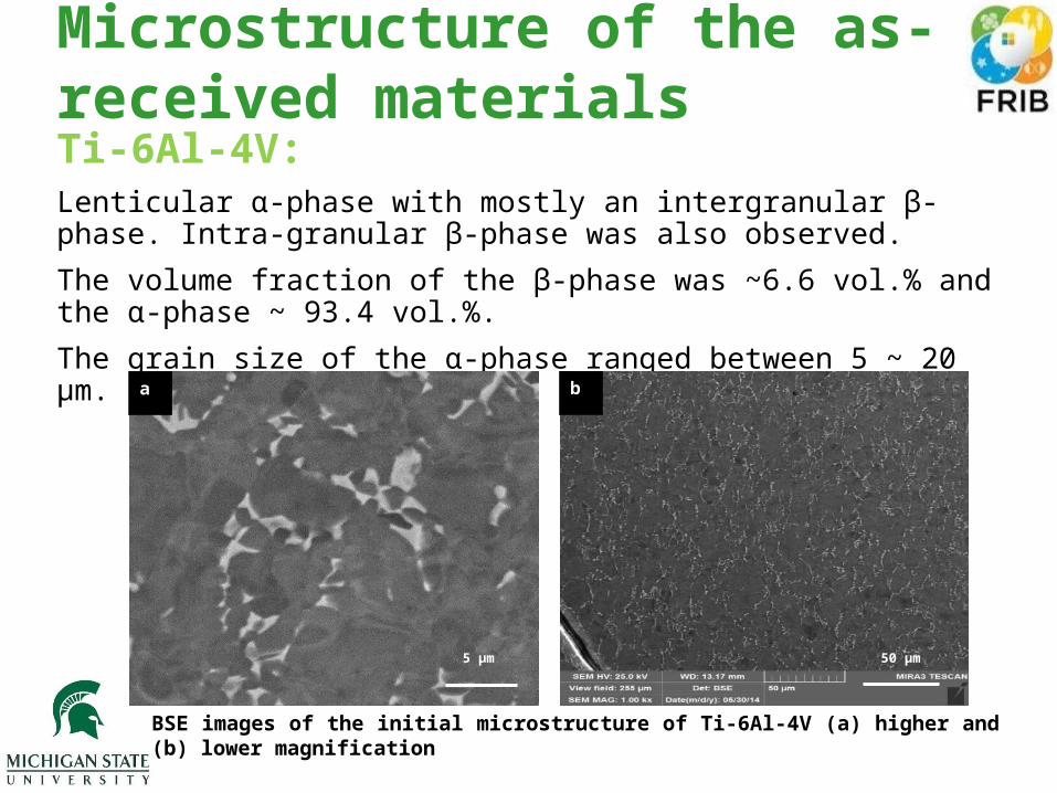
Ti-6Al-4V:Lenticular α-phase with mostly an intergranular β-phase. Intra-granular β-phase was also observed.
The volume fraction of the β-phase was ~6.6 vol.% and the α-phase ~ 93.4 vol.%.
The grain size of the α-phase ranged between 5 ~ 20 µm.
Microstructure of the as-received materials
5 µm 50 µm
a b
BSE images of the initial microstructure of Ti-6Al-4V (a) higher and (b) lower magnification

Ti-6Al-4V-1BThe microstructure contained both an equiaxed (7.4µm) and lenticular α-phase; total volume percent α-phase was ~ 79%. The β-phase volume percent was ~ 15 vol.% while the TiB phase volume percent was ~5.9 vol.%.(Chen et al.)
W. Chen et al / Key Eng. Mater., vol. 436, pp. 195–203, May 2010.
50 µm10 µm
a b
BSE images of the initial microstructure of Ti-6Al-4V-1B (a) higher and (b) lower magnification
Microstructure of the as-received materials

BSE images and IPF maps before (a,b) and after irradiation at the same area (c,d)in a Ti-6Al-4V sample irradiated with 131Xe with an energy of 92 MeV. The fluence was 2.1014 ions.cm-2 and the temperature 25oC
BSE images and IPF maps before (a,b) and after irradiation at the same area (c,d)in a Ti-6Al-4V-1B sample irradiated with 36Ar with an energy of 36 MeV. The fluence was 1.1015 ions.cm-2 and the temperature 350oC
Microstructure Characterization
No change in microstructure or grain orientation at the surface.
Before Before After After a c
b d

Nano-indentation results for Ti-6Al-4V and Ti-6Al-4V-1B irradiated with 36Ar @36 MeV at fluence of 1.1015 ions.cm-2with the CP –Ti foil on the surface.
Hardness measurementsNano-indentationParameters:• Berkovich tip• Strain rate : 0.05s-1
• Poisson ratio=0.33• Distance between
indents: 50µm
A slight increase in hardness observed for the sample irradiated with a higher fluence (1.1015 ions.cm-2) and lower temperature (T = 350oC) for the higher doses
Obtain the properties of the materials in depth.
Ti-6Al-4V-1B
Boron addition to Ti-6Al-4V did not change its irradiation resistance0 500 1000 1500 2000 2500
4
5
6
7
8
9
10
11
12
13
0
0.2
0.4
0.6
0.8
1
1.2
1.4
1.6
Series1UnirradiatedDose (dpa)
Displacement into the surface (nm)
Har
dn
ess
(GP
a)
Dos
e (d
pa)
F = 1.1015 ions.cm-2, T=350oC
0 500 1000 1500 2000 2500 30004
5
6
7
8
9
10
11
12
13
0
0.2
0.4
0.6
0.8
1
1.2
1.4
1.6
Ti64-HT-HF-foil
Ti64-LT-HF-foil
Unirradiated
Dose (dpa)
Displacement into the surface (nm)
Har
dnes
s (G
Pa)
Dos
e (d
pa)
F = 1.1015 ions.cm-2, T=350oCF = 1.1015 ions.cm-2, T=20oC
Ti-6Al-4V
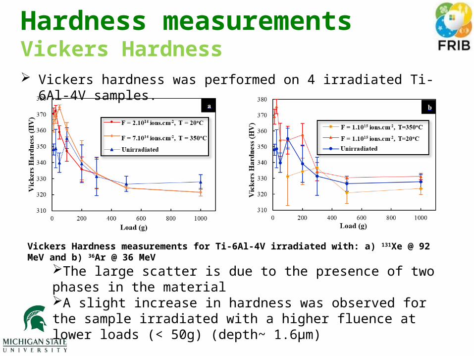
Vickers Hardness measurements for Ti-6Al-4V irradiated with: a) 131Xe @ 92 MeV and b) 36Ar @ 36 MeV
Vickers hardness was performed on 4 irradiated Ti-6Al-4V samples.
The large scatter is due to the presence of two phases in the materialA slight increase in hardness was observed for the sample irradiated with a higher fluence at lower loads (< 50g) (depth~ 1.6µm)
Hardness measurementsVickers Hardness

Relative micro-hardness of the Ti–6Al–4V alloy as a function of applied load for Ti-6Al-4V irradiated with: a) Kr+26@350 MeV (Budzynski et al. 2009) and b) 131Xe @ 92 MeV.
The lower irradiation damage observed in our investigated Ti-6Al-4V samples compared to results reported by Budzynski et al. (2009) could be explained by The difference in microstructure: larger grains (~100µm) The gs was 5-20µm in our material and gbs act as sinks for
radiation-induced-effects
P. Budzynski, V. A. Skuratov, and T. Kochanski, “Mechanical properties of the alloy Ti–6Al–4V irradiated with swift Kr ion,” Tribol. Int., vol. 42, no. 7, pp. 1067–1073, Jul. 2009.
Hardness measurementsVickers Hardness

Effect of the microstructure in the irradiation resistance of this Ti-alloy.
Effect of the small grains (5-20µm)Boron addition causes grain refinementThermomechanical processing can
improve its properties
Discussion
Variation of prior β grain size, d, and the α lath size, λ, in Ti64 with wt.% B addition (Sen et al.)
Sen et al. Acta Materialia, Volume 55, Issue 15, September 2007, Pages 4983-4993,

The analyzed hardness and nano-indentation suggest a higher irradiation damage resistivity in the two studied Ti-alloys than reported in literature for Ti-6Al-4V.
Slight differences in the microstructure caused by the thermomechanical processing may be responsible for this difference.
1% boron addition to Ti-6Al-4V didn’t degrade the radiation resistance
Ongoing and Future work: Irradiation creep test In-situ tensile tests and slip trace analysis: Deformation mechanisms X-ray diffraction: Investigate phase transformation Effect of the microstructure on the irradiation damage in Ti-alloys
Conclusion

Acknowledgements
• MSU Department of Chemical Engineering and Material Science
• FRIB• Mikhail Avilov• Reginald Ronningen
• GANIL-CIMAP• Florent Durantel• Clara Grygiel• Isabelle Monnet• Florent Moisy• Marcel Toulemonde

This material is based upon work supported by the U.S. Department of Energy Office of Science under Cooperative Agreement DE-SC0000661, the State of Michigan and Michigan State University. Michigan State University designs and establishes FRIB as a DOE Office of Science National User Facility in support of the mission of the Office of Nuclear Physics.
Frederique PellemoineWolfgang Mittig
Radiation Damage and Annealing in Graphite: Ways to Improve the Lifetime of Targets

F. Pellemoine, Nov. 2014 MaTX-2, GSI
• FRIB High-power production targets • Design and challenges• Irradiation and annealing studies of graphite
• Temperature effect
• NSCL-FRIB stripper• Challenges• Irradiation and annealing studies of graphite
• Temperature effects
• Conclusions
Outline

F. Pellemoine, Nov. 2014 MaTX-2, GSI
• In-flight rare isotope beam production with beam power of 400 kW at 200 MeV/u for 238U and higher energies for lighter ions
• High power capability• Up to 100 kW in a ~ 0.3 - 8 g/cm² target for rare
isotope production via projectile fragmentation and fission
• Required high resolving power of fragment separator
• 1 mm diameter beam spot • Maximum extension of 50 mm in
beam direction
• Target lifetime of 2 weeks to meet experimental program requirements
High-Power Production Target Scope and Technical Requirements
Preseparator
Primary Beam Production target

F. Pellemoine, Nov. 2014 MaTX-2, GSI
Beam
• Rotating multi-slice graphite target chosen for FRIB baseline
• Increased radiating area and reduced total power per slice by using multi-slice target
• Use graphite as high temperature material• Radiation cooling
• Design parameters• Optimum target thickness is ~ ⅓ of ion
range• 0.15 mm to several mm
• Maximum extension of 50 mm in beam direction including slice thickness and cooling fins to meet optics requirements
• 5000 rpm and 30 cm diameter to limit maximum temperature and amplitude of temperature changes
FRIB Production TargetRotating Multi-slice Graphite Target Design
Multi-slice target / heat exchanger
Shield block
Radiation resistance and vacuum compatible motor

F. Pellemoine, Nov. 2014 MaTX-2, GSI
• Thermo-mechanical challenges• High power density: ~ 20 - 60 MW/cm³
• High temperature: ~ 1900 ºC: Evaporation of graphite, stress• Rotating target
• Temperature variation: Fatigue, Stress waves through target
• Swift Heavy Ion (SHI) effects on graphite• Radiation damage induce material changes
• Property changes: thermal conductivity, tensile and flexural strength, electrical resistivity, microstructure and dimensional changes, …
• Swift heavy ions (SHI) damage not well-known• 5·1013 U ions/s at 203 MeV/u may limit target lifetime
• Fluence of ~9.4·1018 ions/cm² and 10 dpa estimated for 2 weeks of operation
• Similar challenges at • Facility for Antiproton and Ion Research (FAIR) at GSI • Radioactive Ion Beam Factory (RIBF) at RIKEN
FRIB Production TargetChallenges

F. Pellemoine, Nov. 2014 MaTX-2, GSI
• Polycrystalline isotropic graphite• 2 Grades MERSEN 2360 (5 μm ) / 2320 (13 μm)
• Irradiation test at UNILAC at GSI/Darmstadt• Au-beam 8.6 MeV/u
• Up to 5.6·1010 ions/cm²·s and fluence up to 1015 ions/cm² • Equivalent to a fluence of 1018 ions/cm² for FRIB beam energy
or 2 days of operation• Electronic energy loss ≈ 20 keV/nm
• Ohmic heating (up to 35 A, 250 W) of samples to different temperature during irradiation
Irradiation Test at UNILAC at GSI/Darmstadt
D I
D I
D I
I = 35 A I = 35 A + beam
Tmax = 1480 (± 30 ºC) Tmax = 1635ºC

F. Pellemoine, Nov. 2014 MaTX-2, GSI
Swelling is completely recovered at 1900ºC
Radiation Damage Studies in Graphite [1]Annealing of Damage at High Temperature (> 1300ºC)
X-Ray Diffraction analyses
TEM analyses
1 A - 350C1014 cm-²
11 A - 750°C 1014 cm-²
25 A - 1205°C 1014 cm-²
35 A - 1635°C 1015 cm-²
F. Pellemoine, Nov. 2014 MaTX-2, GSI
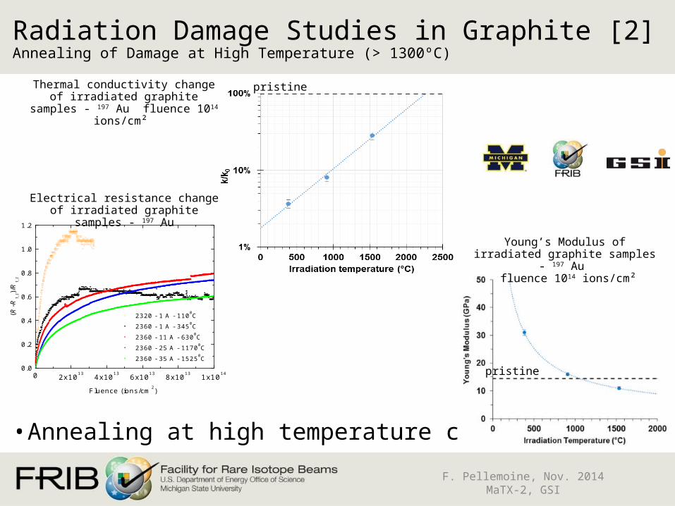
• Annealing at high temperature confirmed
Radiation Damage Studies in Graphite [2]Annealing of Damage at High Temperature (> 1300ºC)
0 2x10¹³ 4x10¹³ 6x10¹³ 8x10¹³ 1x10140.0
0.2
0.4
0.6
0.8
1.0
1.2
2320 - 1 A - 1100C
2360 - 1 A - 3450C
2360 - 11 A - 6300C
2360 - 25 A - 11700C
2360 - 35 A - 15250C
(R-R
1,I)/
R1,
I
Fluence (ions/cm2)
Young’s Modulus of irradiated graphite samples - 197 Au
fluence 1014 ions/cm²
Thermal conductivity change of irradiated graphite samples - 197 Au
fluence 1014 ions/cm²
Electrical resistance change of irradiated graphite samples - 197 Au
pristine
pristine
F. Pellemoine, Nov. 2014 MaTX-2, GSI
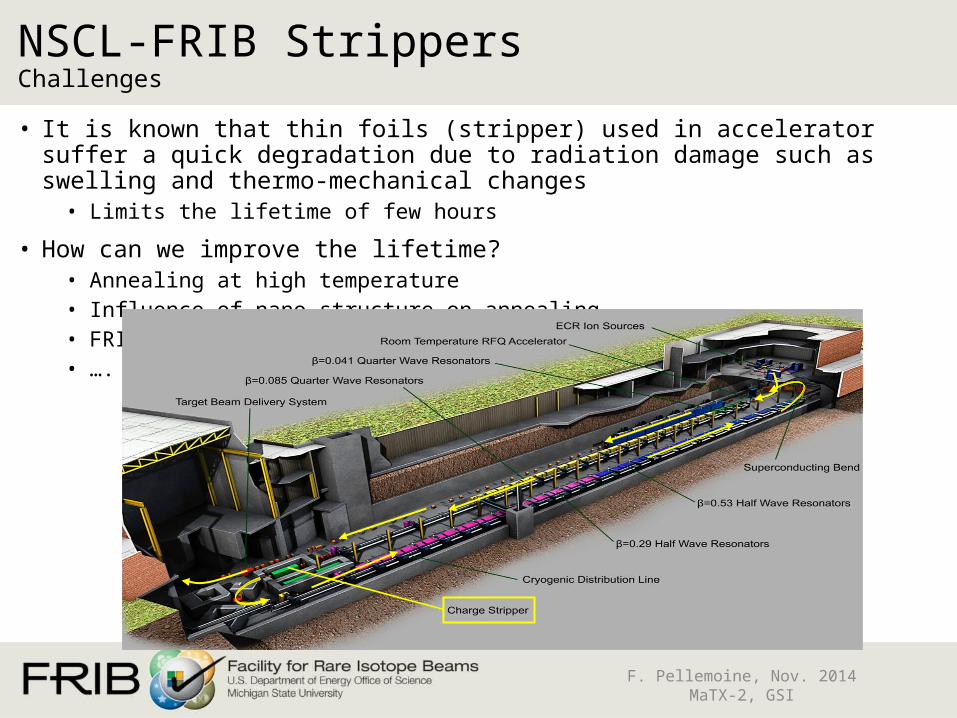
• It is known that thin foils (stripper) used in accelerator suffer a quick degradation due to radiation damage such as swelling and thermo-mechanical changes
• Limits the lifetime of few hours
• How can we improve the lifetime?• Annealing at high temperature• Influence of nano-structure on annealing• FRIB full intensity Li film stripper• ….
NSCL-FRIB Strippers Challenges

F. Pellemoine, Nov. 2014 MaTX-2, GSI
• Recent tests at NSCL have shown quick deterioration of graphite foils under heavy ion bombardment due to thermal and mechanical stresses and radiation damage
• Carbon irradiated with Pb beam @ 8.1 MeV/u• Se= 24 keV/nm, fluence = 4.5·1016 ions/cm²
NSCL-FRIB StrippersRadiation Damage
F. Marti et al., "A carbon foil stripper for FRIB", TUP 106, Proceedings of Linear Accelerator Conference LINAC2010, Tsukuba, Japan, TUP105, 2010.
SEM photographs of unused carbon foil (left) showing a small pinhole for illustration and a foil exposed to 8.1 MeV/u Pb beam

F. Pellemoine, Nov. 2014 MaTX-2, GSI
NSCL-FRIB Strippers Irradiated Strippers at NSCL
Current carbon strippers used at NSCL

• Previous studies [3] showed annealing effects of radiation damage at high temperature. The heating by the beam was evaluated to produce temperatures of up ~900 ºC. A clear tendency of increased lifetime with irradiation temperature was observed.
• The lifetime of the 10 multilayer foil C-DLC-B was significantly higher (factor 3) than the standard C-NSCL foils. The 10 multilayer foil C-DLC was somewhat superior (about a factor 2) as compared to the standard foils.
Improvement of the lifetime
F. Pellemoine, Nov. 2014 MaTX-2, GSI , Slide 28
Lifetime time (μA·h/cm²) as a function of the irradiation temperature and the microstructure of graphite stripper foils.
[3] S. Fernandes et al., “In-Situ Electric Resistance Measurements and Annealing Effects of Graphite Exposed to Swift Heavy Ions”, Nucl. Instrum. Methods Phys. Res. B 314 (2013) 125-129.
F. Pellemoine, Nov. 2014 MaTX-2, GSI
• Heavy-ion irradiation tests and annealing studies performed in the context of high-power target and strippers for high intensity accelerator were performed
• High temperature annealing of heavy-ion induced radiation damage observed in production target
• First experiment of this kind• Confirmed by several analysis
• Graphite as a material for FRIB beam production targets promises sufficient lifetime
• High temperature annealing of heavy-ion induced radiation damage observed in NSCL strippers
Summary and Conclusions

F. Pellemoine, Nov. 2014 MaTX-2, GSI
• FRIB/NSCL Michigan State University• Mikhail Avilov, Saul Beceiro Novo, Sandrina Fernandes, Felix
Marti, Mike Schein, Andreas Stolz, Genevieve West
• GSI Helmholtzzentrum für Schwerionenforschung GmbH • Markus Bender, Markus Krause, Daniel Severin, Marilena Tomut,
Christina Trautmann
• University of Michigan • Rodney Ewing, Maik Lang, Weixing Li
Acknowledgements

F. Pellemoine, Nov. 2014 MaTX-2, GSI
Thank you for your attention
FRIB construction area – October 27 2014

F. Pellemoine, Nov. 2014 MaTX-2, GSI
• Effect of the temperature on lifetime improvement observed at NSCL
NSCL-FRIB Strippers Lifetime measurement at NSCL
Preliminary results
78 Kr14+ @ 13 MeV/u
20 Ne @ 3.2 MeV
Sugai et al., NIMB 269 (2011) 223-228