grasp invariance - robotics institute
TRANSCRIPT

Grasp Invariance∗
Alberto Rodriguez and Matthew T. Mason
August 15, 2011
Abstract
This paper introduces a principle to guide the design of finger form: invariance of con-tact geometry over some continuum of varying shape and/or pose of the grasped object inthe plane. Specific applications of this principle include scale-invariant and pose-invariantgrasps. Under specific conditions, the principle gives rise to spiral shaped fingers, includinglogarithmic spirals and straight lines as special cases. The paper presents a general tech-nique to solve for finger form, given a continuum of shape or pose variation and a propertyto be held invariant. We apply the technique to derive scale-invariant and pose-invariantgrasps for disks, and we also explore the principle’s application to many common devicesfrom jar wrenches to rock-climbing cams.
1 Introduction
What principles should guide the design of finger form? It depends on context—the specificapplication, the hand design philosophy, and in particular on the function assigned to thefingers. In this paper we explore the possible role of fingers in adapting to variations in objectshape and pose. One common design approach is to adapt to those variations by active controlof several actuators per finger. But for simpler hands, with one actuator per finger, or even oneactuator driving several fingers, the job of gracefully adapting to shape and pose variations mayfall on the finger form. This work explores grasp invariance over shape and/or pose variationas a principle for finger form design.
We begin by proposing a geometry problem:
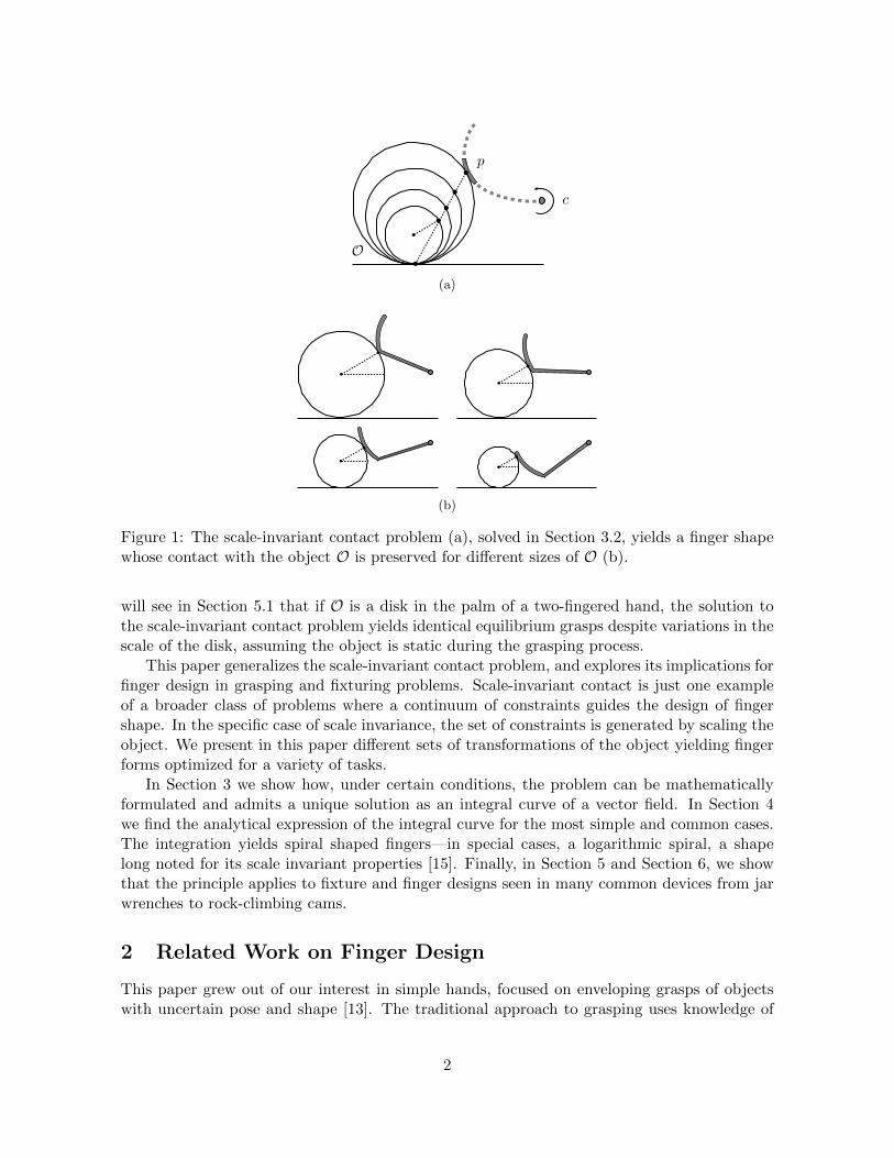
Scale-invariant contact problem: Given O an object shape in the plane, p a pointon the boundary of O, and c the location of the finger’s revolute joint, find thefinger shape that makes contact at p despite scaling of O (Figure 1).
A solution to the previous problem yields a finger shape that preserves contact locationas well as contact normal with the scale of the object. As a consequence, many propertiesgoverning the mechanics of grasping and manipulation are also preserved. For example, we
This work was supported by National Science Foundation, the Defense Advanced Research Projects Agencyand Army Research Laboratory under cooperative agreement number W911NF-10-2-0016. This work does notnecessarily reflect the position or the policy of the U.S. Government, DARPA or ARL. No official endorsementshould be inferred.
∗An earlier version of this paper appeared in proceedings of the 2010 Workshop on Algorithmic Foundationsof Robotics (WAFR).
1
(a)
(b)
Figure 1: The scale-invariant contact problem (a), solved in Section 3.2, yields a finger shapewhose contact with the object O is preserved for different sizes of O (b).
will see in Section 5.1 that if O is a disk in the palm of a two-fingered hand, the solution tothe scale-invariant contact problem yields identical equilibrium grasps despite variations in thescale of the disk, assuming the object is static during the grasping process.
This paper generalizes the scale-invariant contact problem, and explores its implications forfinger design in grasping and fixturing problems. Scale-invariant contact is just one exampleof a broader class of problems where a continuum of constraints guides the design of fingershape. In the specific case of scale invariance, the set of constraints is generated by scaling theobject. We present in this paper different sets of transformations of the object yielding fingerforms optimized for a variety of tasks.
In Section 3 we show how, under certain conditions, the problem can be mathematicallyformulated and admits a unique solution as an integral curve of a vector field. In Section 4we find the analytical expression of the integral curve for the most simple and common cases.The integration yields spiral shaped fingers—in special cases, a logarithmic spiral, a shapelong noted for its scale invariant properties [15]. Finally, in Section 5 and Section 6, we showthat the principle applies to fixture and finger designs seen in many common devices from jarwrenches to rock-climbing cams.
2 Related Work on Finger Design
This paper grew out of our interest in simple hands, focused on enveloping grasps of objectswith uncertain pose and shape [13]. The traditional approach to grasping uses knowledge of
2

object geometry and grasp mechanics to plan for contact points. In this context the details ofphalange form are of little consequence, since only the tip of the finger is involved in the grasp.
Simple hands, however, do not necessarily have the required capabilities to plan for contactpoints. The actual forms of the phalanges and the palm become important when the locationsof contacts are not carefully planned and controlled. Simple hands adapt to varying shapesand poses by the emergent interaction of hand with object, rather than by actively driving thehand shape to conform to a known object shape and pose.
Several other approaches are evident in previous hand design literature. The envelopinggrasps we employ are contrasted with fingertip grasps, more suited to the traditional approachto grasping. The dichotomy between enveloping and fingertip grasps corresponds roughly to thedistinction between power and precision grasps in Cutkosky and Wright’s grasp taxonomy [8].
While much of the analysis of grasp has focused on local stability and in-hand manipulationwith fingertip grasps [5], hand design research has explored various grasp types more broadly.The work leading to the design of the Barrett Hand [19, 18, 1] explored a single finger probe, apinch grasp , both cylindrical and spherical enveloping grasps, a two-fingered fingertip grasp,and a hook grasp. The design of the DLR-II likewise was guided by the desire to produce bothpower and precision grasps [7].
Unlike the work cited so far, our approach does not change the shape of the fingers toadapt to an object pose or shape. Instead, adaptation emerges from the interaction of fixedfinger shapes with the object. In that respect the closest work is Trinkle and Paul’s [17] workon enveloping grasps, Dollar and Howe’s [10] work on hands with compliantly coupled joints,and Theobald et al.’s [14] design of a gripper for acquiring rocks. Still, none of the abovefocus on the actual finger form. Dollar and Howe [9] surveyed 20 different designs of compliantand underactuated hands, and all employ cylindrical or straight fingers, occasionally employingsome additional shape features, but with no particular principle described to guide their design.
Our interest in shape design has some commonalities with work on algorithmic approachesto the design of chamfers and traps. Whitney, Gustavson and Hennessey [20] proposed proce-dures to design straight and curved chamfers to aid in the assembly of rigid parts. Berrettyet al. [4] reasoned about the geometry of object/trap interaction in vibratory bowl feeders forobject filtering.
Work on fence design in the context of parts feeding [12, 21, 3] is also relevant to this paper.When objects on a conveyor make contact with a fence, the resulting interaction can reduceuncertainty in object pose. Because of frictional uncertainty, as the parts lose contact withthe fence, there is always some remaining uncertainty in object pose. Brokowski, Peshkin andGoldberg [6] designed curved fence tails to minimize the effect of frictional uncertainty. Thetechnique proposed in [6] for fence tail design has some similarities with the recipe we providein this paper to solve for finger shape.
Still in the context of parts feeding, Zhang and Goldberg [22] systematized the design ofparallel jaw grippers for alignment of parts in the vertical plane. They proposed to use fourgripper point contacts to passively align the part in the vertical plane as the jaws close.
The closest work to this paper is found not in robotics research, but in the design of varioustools and hardware. All the devices in Figure 2 adapt to shape and pose variations withoutchanging their internal shape. Instead, the adaptation arises from their designed curvature. Inthe cases of the rock-climbing cam [11] and the anti-kickback device [2] the shape was derivedtheoretically. The others, to our knowledge, are the product of human intuition. In Section 6we analyze their shape under the grasp invariance principle.
3

(a) (b)
(c) (d) (e)
Figure 2: Curved shapes used in: (a) Truck door lock; (b) Jar opener; (c) Anti-kickback devicefor table saw; (d) Pliers; (e) Climbing cam.
3 Problem Formulation
In this section we generalize the formulation of the scale-invariant contact problem proposed inthe introduction by considering now an arbitrary continuum of transformations of the object O.As in the original problem, the interest lies in designing a finger that makes contact with O ata given point p, and preserves the contact geometry with respect to the set of transformations.
Let H(t, s) be a parametrization of the object boundary for the continuum of transfor-mations, where s is the transformation parameter and t the boundary parameter. For anygiven value of the transformation parameter s, hs(t) = H(t, s) parametrizes the boundary ofthe transformed object O, with hs(0) mapping to the desired contact point p. Under thisformulation, we generalize the scale-invariant contact problem as:
Invariant contact problem: Given O an object shape in the plane, H(t, s) a contin-uous parametrization of a set of transformations of the object, and c the locationof the finger’s revolute joint, find the finger shape that makes first contact with theobject at H(0, s) for all s.
Locally, requiring the finger to contact the object at p constrains the finger slope: fingerand object must be tangent. In the following section we show that this interpretation leads toa reformulation of the problem in terms of vector fields.
3.1 Local Formulation of the Problem
Let contact curve L(s) = H(0, s) describe the locus of the contact point p with the transfor-
mation of the object, and let contact vector V(s) = ∂H(t,s)∂t |t=0 be the tangent to the object
along the contact curve, as in Figure 3.Every instance of the object corresponds to a point in the contact curve L, for which the
invariant contact problem imposes a constraint on the slope of the finger: it must be tangentto the contact vector V; and a constraint on its curvature: the curvature of finger and objectneed to comply with each other so that there is no interpenetration. We will see in Section 3.3that the curvature constraints are key to decide whether the invariant contact problem has asolution or not. We proceed in this section by showing how the set of slope constraints fullydefines the finger form.
4

Figure 3: The transformation of the object O defines the contact points pi = H(0, si) and withthem, the contact curve L and the contact vector V.
If we overlook the possibility of interpenetration between finger and object, the local versionof the invariant contact problem formulates as:
Local invariant contact problem: Given O an object shape in the plane and aparametrized set of transformations for which L is the contact curve and V thecontact vector, and c the location of the finger’s revolute joint, find the fingershape that always crosses the contact curve tangent to the contact vector.
Every point in the contact curve L yields a tangential constraint at a specific point alongthe finger. The map between points in the contact curve and points along the finger must beinjective, since the slope of the finger cannot satisfy two different constraints simultaneously.To formulate that requirement we introduce the scalar function r(s), the distance between eachone of the points in the contact line L and c, the center of rotation of the finger.
As illustrated in Figure 4a, while the finger rotates, each tangential constraint is propagatedalong an arc of radius r(s) and center c (parallel transport of the contact vector V(s)). Whenapplying the same construction to the entire set of constraints, as in Figure 4b, it follows thatthe scalar function r(s) must be strictly monotonic, otherwise two different points along thecontact line could possibly impose two different slope constraints along the same concentricarcs. If it is the case that r(s) reaches an extremum, the map between points in the contactcurve and points along the finger will not be injective and the invariant contact problem willimpose inconsistent constraints.
In practice, given a parametrized transformation H(t, s) of the object and its correspondentcontact curve, we avoid inconsistent constraints by restricting the synthesis process to a sectionof the contact curve where r(s) is strictly monotonic, Figure 5. We will refer to a problem thatavoids inconsistent constraints as a proper problem.
If we have a proper problem, the parallel transport of the contact curve and contact vectoralong concentric arcs yields a vector field F defined on an annulus in the plane. By construction,any integral curve of F must satisfy all contact curve constraints, hence it should be a solutionto the local invariant contact problem.
We will see in Section 3.2 that the set of tangential constraints fully defines the finger form.In Section 3.3 we argue that smoothness of the contact curve as well as the travel of the contactvector is enough to guarantee the existence of solution to the local invariant contact problem.
5

(a)
(b)
Figure 4: (a) Parallel transport of V(s) radially from c. (b) Extending the same constructionto the entire set of tangential constraints gives us the vector field F .
Finally, we discuss when a solution to the local invariant contact problem is also a solution tothe mor general invariant contact problem.
3.2 General Solution Recipe
The derivation in the previous section suggests a three step general procedure for obtainingthe shape of the finger:
1. Given an object O and a parametrized transformation H(t, s), construct the contactcurve L and the contact vectors V.
2. Obtain the vector field F , by rotating L and V around the rotation center c.
3. Find the shape of the finger as an integral curve of F .
Figure 6 shows an example of the procedure applied to the original scale-invariant contactproblem for a disk-shaped object resting in a planar palm. When scaling the disk, the contactcurve L becomes a line and the contact vector V is constant along L.
The continuous set of transformations H(t, s) induces a continuous set of tangential con-straints. Assuming that we have a proper problem, the vector field is well defined in a contin-
6

Figure 5: Example of maximal section of the contact curve L for which r(s) is strictly mono-tonic. The minimum value of r(s) is chosen at p1. The value of r increases with the contactcurve until reaching p2, where an extremum prevents a further extension.
Figure 6: Step by step execution of the general recipe to obtain the form of the finger forthe scale-invariant contact problem. Step 1: Construction of the contact curve L and contactvector V. Step 2: Generation of the vector field F . Step 3: Integral curve of F .
uum of the space, and, hence, the finger form is fully defined. In the next section we see thatthe existence of the integral curve is guaranteed provided some regularity of H.
3.3 Existence and Feasibility of Solution
It follows from the previous sections that the solution to the local invariant contact problemis subject to the existence of an integral curve of the vector field F . We rely on the theoremof existence and uniqueness of maximal integral curves [16] for that.
Theorem 1 (Existence and Uniqueness of Maximal Integral Curves) Let X be a smoothvector field on an open set U ∈ Rn+1 and let p ∈ U . Then there exists a unique and maximalintegral curve α(t) of X such that α(0) = p.
By virtue of Theorem 1 the existence of the integral curve depends on the smoothness ofthe vector field F . If the contact curve L is smooth and V changes smoothly along it, the vectorfield will also be smooth, since the parallel transport along concentric arcs is a continuous anddifferentiable operation. If that is the case, the solution to the local invariant contact problemis guaranteed to exist for the restricted interval of values of s where the problem is a properproblem.
For this to also be a solution to the invariant contact problem, we need to check that it doesnot induce interpenetration between finger and object. There are two types of interpenetrationthat tend to happen in the vicinity of convexities of the object:
• Local interpenetration: As mentioned in the beginning of Section 3.1, being tangent
7

to the object is not enough to guarantee that locally object and finger contact at p,Figure 7a. Their curvature must comply with each other.
• Global interpenetration: Even if curvatures of finger and object comply locally, othersections of the finger might collide with the object, Figure 7b.
(a) (b)
Figure 7: Examples of interpenetration between finger and object. In both examples, the fingercontacts the object at the desired location (black dot) with the right slope. However, that isnot enough for the finger to be a solution to the invariant contact problem. (a) Curvatures offinger and object are not adequate to prevent local interpenetration. (b) Even with adequatecurvatures, interpenetration can happen with the rest of the object O.
Given that the tangential constraints fully define the finger form, the solution to the contactinvariant problem is either that same finger form or no solution at all, when it implies anyform of interpenetration. Hence, we should add a fourth step to the general solution recipein Section 3.2, where we check for the feasibility of the solution yielded by the integration ofthe vector field. If we are given the freedom to play with some of the givens of the problem,such as the contact point p or the location of the rotation center of the finger c, dealing withinterpenetration becomes a design issue.
4 Analytic Solution
The recipe in Section 3.2, along with numerical integration, provides a method to find the fingerform for any given object O and any parametrized transformation H(t, s). In this section wefind the analytical expression of the finger shape for some specific cases, namely when thecontact curve is a line and the contact vector is constant along it. Note that this includes thecases of scaling of the object, translation of the object, or any linear combination of both.
Let (x, y) and (r, θ) be the cartesian and polar coordinates in the plane. The shape of thefinger is the solution to the system of first order differential equations:
x = Fxy = Fy
(1)
where F = (Fx,Fy) is the vector field obtained in Section 3.2. The identity in Equation 2relates the derivatives of cartesian and polar coordinates:
dy
dx=r′ sin θ + r cos θ
r′ cos θ − r sin θ(2)
where r′ = drdθ . With it, we can rewrite the cartesian system 1 as the single polar differential
equation:FyFx
=r′ sin θ + r cos θ
r′ cos θ − r sin θ(3)
8

Figure 8: Normalized diagram for Case I: The parallel transport of V along an arc with centerc gives us F(x, y), the direction of the vector field at (x, y), α = α0 + θ + π
2 .
Without loss of generality we normalize the geometry of the problem and suppose that thecontact curve L is parallel to the Y axis and the center of rotation c lies on the X axis. Let α0
be the constant angle between L and the contact vector V. Depending on the relative locationof c and L we distinguish three cases that we will analyze separately in the next three sections:
i. The rotation center c lies on top of L.
ii. The rotation center c is at finite distance from L.
iii. The rotation center c is at infinity, i.e. the finger translates rather than rotates.
4.1 Case I: Rotation Center On the Contact Curve
In this case the distance between the center of rotation of the finger c and the contact curveL is zero. We place the origin of coordinates at c and the axis Y along the contact curve, asin Figure 8. In this case, Equation 3 becomes:
FyFx
= tan(α0 + θ +
π
2
)=r′ sin θ + r cos θ
r′ cos θ − r sin θ(4)
Solving Equation 4 for r′ yields:
r′ =dr
dθ= −r tanα0 (5)
Equation 5 is a linear homogeneous ordinary differential equation with solution:
r (θ) = C e−θ tanα0 (6)
The solution to the invariant contact problem for case I is a logarithmic spiral with pitchπ2 + tan−1 (cotα0), which we could have anticipated from Figure 8 where the angle betweenthe contact vector and the radial line (line from origin to the finger) is constant. This is
9

Figure 9: Normalized diagram for Case II: The parallel transport of V along an arc with centerc gives us F(x, y), the direction of the vector field at (x, y), α = α0 + θ + β.
characteristic of logarithmic spirals and gives them their scale invariant properties [15], as wewill further see in Section 6.
Notice that when the angle α0 reaches one of the limit values ±π2 , the logarithmic spiral
becomes a straight line. This is caused by the contact vector becoming parallel to the contactline.
4.2 Case II: Rotation Center at Finite Distance from Contact Curve
In this case the rotation center c is at finite distance from the contact line L. Without lossof generality we can scale the geometry of the problem so that the distance is unity. As inthe previous case, we place the origin of coordinates at c. Now the contact line is vertical andcrosses the X axis at (1, 0), as in Figure 8.
Equation 3 particularized to the construction in Figure 9 yields:
FyFx
= tan (α0 + θ + β) = tan
[α0 + θ + cos−1
(1
r
)]=r′ sin θ + r cos θ
r′ cos θ − r sin θ(7)
After some trigonometric algebra, Equation 7 can be solved for r′ as:
r′ =dr
dα= r · cosα0 −
√r2 − 1 sinα0
sinα0 +√r2 − 1 cosα0
(8)
Equation 8 is a separable differential equation with form drdθ = g(r), which can be solved as
10
θ(r) =∫dθ =
∫1g(r)dr, with the change of variables t→
√r2 − 1:
θ(r) =
∫1
r· sinα0 +
√r2 − 1 cosα0
cosα0 −√r2 − 1 sinα0
dr =
=
∫t
t2 + 1· (sinα0 + t cosα0)
(cosα0 − t sinα0)dt =
= −∫
1
t2 + 1+
cosα0
sinα0t− cosα0dt =
= − tan−1 (t)− ln (| sinα0t− cosα0|)tanα0
(9)
As illustrated in Figure 10, Equation 9 yields the α0-parametrized family of spirals:
θ(r) = − tan−1(√
r2 − 1)−
ln(| sinα0
√r2 − 1− cosα0|
)tanα0
+ C (10)
The solution is valid for all possible values of α0 except when tanα0 = 0, in which case asimilar derivation yields:
θ (r) = − tan−1(√
r2 − 1)
+√r2 − 1 + C (11)
4.3 Case III: Rotation Center at Infinity
In this case the center of rotation c is located at infinity. This is equivalent to a translatingfinger, i.e., the finger joint is prismatic rather than revolute.
The vector field F is in this case generated by the parallel transport of the contact curveand contact vector along parallel lines oriented with the direction of translation. The obtainedvector field is independent of the direction of translation: F is constant across the entire planeand oriented with α0 except in the singular case when the direction of translation is parallelto the contact line. In this case the vector field is only defined on top of the contact line.
The integral curve of F is always a line segment aligned with the constant contact vector V,which yields straight fingers. In the degenerate situation of the direction of translation beingaligned with the contact line, the solution only exists if the contact vector is also aligned withthe contact line, in which case the integral curve is also a straight line segment.
4.4 Family of Solutions
In cases I and II, the integral curve of the vector field is a spiral, with the exception of a fewdegenerate situations where the integral curve is either a line segment or a circle. We makespecial note of case I with α0 = 0 where the contact vector is perpendicular to the contact line.This produces an impractical circular finger that only meets one of the constraints, while, atthe same time, does not violate any of the rest.
In case III, we always obtain a line segment. Figure 10 shows a summary of the solutionsfor different values of α0. Note that the vector fields obtained with α0 and α0 + π always havethe same magnitude and opposite direction, hence it suffices to analyze the range
[π2 ,−
π2
]. In
Figure 10 we show a long section of the spiral. However, for practical reasons, the actual shapeof the finger is just a small portion.
11

Case I Case II Case III
α0 = π2
−5 0 5−5
0
5
−5 0 5−5
0
5
−5 0 5−5
0
5
α0 = π4
−5 0 5−5
0
5
−5 0 5−5
0
5
−5 0 5−5
0
5
α0 = 0
−5 0 5−5
0
5
−5 0 5−5
0
5
−5 0 5−5
0
5
α0 = −π4
−5 0 5−5
0
5
−5 0 5−5
0
5
−5 0 5−5
0
5
α0 = −π2
−5 0 5−5
0
5
−5 0 5−5
0
5
−5 0 5−5
0
5
Figure 10: Plots show the contact curve (vertical bold line), the rotation center (grey dot), andthe finger solution (grey curves) for different values of α0. The finger always crosses the lowerhalf of the contact curve with constant angle α0. Case I: Rotation center on the contact curve.Case II: Rotation center at finite distance from the contact curve. Case III: Rotation centerat infinity.
12

(a)
(b)
Figure 11: (a) Contact curve L and contact vector V of the fingers of a scale invariant gripper.(b) Corresponding normalized diagram, where α0 = β.
5 Applications to Grasping
In this section we apply the grasp invariance principle to design fingers of grasping hands. Wegive examples with both scale and pose transformations.
5.1 Scale Invariant Grasping
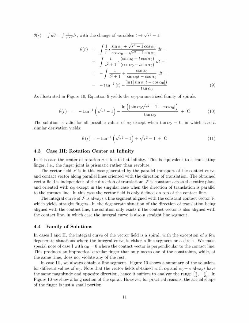
The solution to the scale-invariant contact problem in Figure 1 yields a finger with invariantcontact geometry for a disk of varying size. Two such fingers give a gripper whose equilibriumgrasps are geometrically invariant with scale. Suppose we aim for a triangular grasp betweentwo fingers and a palm. Figure 11a shows the corresponding contact line L and contact vectorV. After the normalization of the geometry proposed in Section 4, we get the diagram inFigure 11b. The solution belongs to the family of spirals obtained in Case II in Section 4.2,where the center of rotation is at finite distance from the contact line.
The contact line, the contact vector, and the form of the finger depend on the object O andthe type of contact we aim for. Therefore, the form of the finger depends on the task to solve.For the specific example of a disk and the triangular grasp in Figure 11a, we can construct ascale-invariant gripper by combining two identical but symmetric fingers as in Figure 12.
5.2 Pose Invariant Grasping
Here we aim to design a hand whose grasps are invariant with respect to the location of agiven object rather than scale. Suppose again that we want to grasp a disk of a given sizewith a triangular grasp, against a planar palm. Now, the disk can be located anywhere along
13
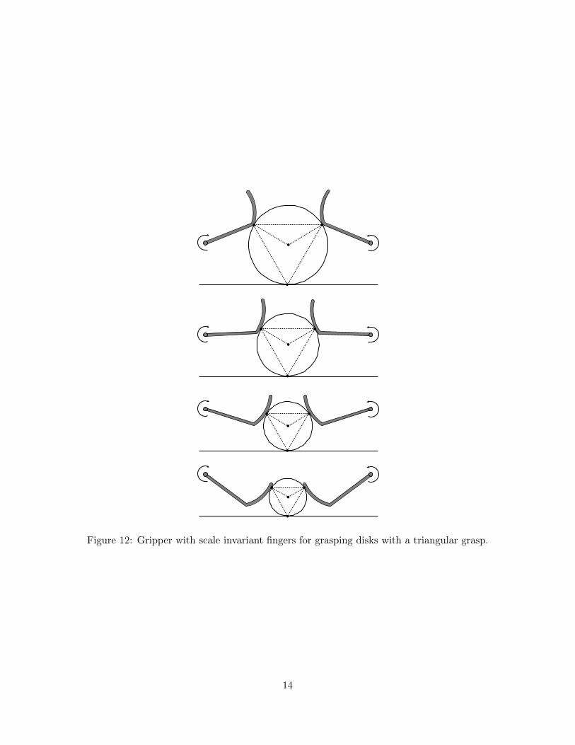
Figure 12: Gripper with scale invariant fingers for grasping disks with a triangular grasp.
14

(a)
(b)
Figure 13: (a) Contact curve L and contact vector V of the fingers of a pose invariant gripper.(b) Corresponding normalized diagram, where α0 = β.
the palm, and we want the grasp geometry to be invariant with respect to that displacement.Figure 13a shows the corresponding contact line L and contact vector V, and Figure 13b showsthe corresponding normalized diagram. Since the rotation center is at finite distance from thecontact line, the solution belongs to the family of spirals in Case II in Section 4.2.
Again, the contact line, the contact vector and consequently the form of the finger dependon the object O and the type of contact desired. In Figure 14 two identical but symmetricfingers compose a pose-invariant gripper.
5.3 Pick-up Tool
Suppose we are to design a gripper with two rigid fingers to pick up an object from the ground.The object needs to slide along the length of the fingers while it is being lifted, similar to Trinkleand Paul’s work on dexterous manipulation with sliding contacts [17]. Because of the criticalrole that contact geometry plays in the sliding motion, complex lift plans can be simplified ifthe contact geometry between finger and object were to be invariant with respect to the liftingmotion. With that in mind, we can use the grasp invariance principle to find the finger shapethat preserves a contact suitable for sliding. Figure 15 shows a gripper designed to pick updisks.
6 Applications to Common Devices
In this section we apply the grasp invariance principle to derive optimal shapes for threecommon devices: a rock-climbing cam, an anti kickback device for table saws and a jar wrench.
15
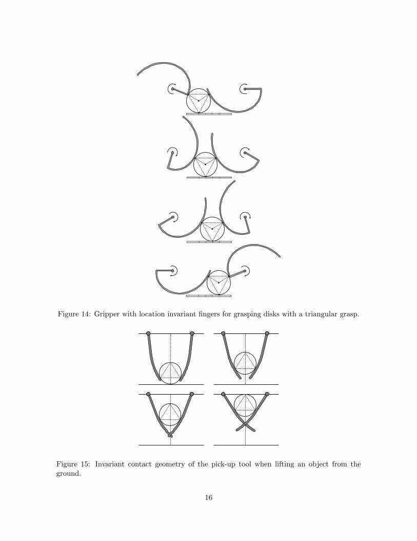
Figure 14: Gripper with location invariant fingers for grasping disks with a triangular grasp.
Figure 15: Invariant contact geometry of the pick-up tool when lifting an object from theground.
16

(a) (b)
Figure 16: (a) Spring loaded cam for rock-climbing. (b) Static force diagram.
6.1 Rock-Climbing Cam
A spring loaded cam is a safety device used in rock climbing to secure anchor points in cracksin the rock face. The device uses the mechanical advantage of the wedge effect to convertpulling force into huge friction forces, (Figure 16a). That conversion depends on the coefficientof friction of the wall µ and the cam angle β. From the diagram on Figure 16 (b) the conditionfor static equilibrium (zero torque at rotation center c) is:
r · Ff cosβ = r · FN sinβ
[Ff ≤ µFN ] FN tanβ ≤ µFNβ ≤ tan−1 µ (12)
where r is the distance from the cam rotation center c to the contact point, FN is the normalforce caused as a reaction to the pulling force Fp, and Ff is the frictional force. For a camto have a loading pattern invariant with the size of the crack it needs to preserve the contactangle β while the cam opens and closes to adapt to different wall widths.
Each wall width imposes a tangential constraint on the form of the cam. We can apply theinvariant contact principle to derive a shape for the cam so that β remains constant despitevariations in d. The rotation center lies on top of the contact line L, hence the solution is alogarithmic spiral with α0 = β (Case I in Section 4.1) as shown in Figure 17.
The logarithmic spiral has been used for decades in the design of climbing cams. Theinvention of modern rock-climbing cams is attributed to Raymond Jardine [11]. His inventionused a logarithmic spiral, with camming angle β = 13.5◦.
6.2 Anti Kickback Device for Table Saws
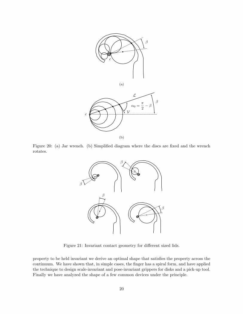
Table saw kickback happens when the blade catches the workpiece and violently throws itback to the front of the saw, towards the operator. An anti kickback device is a passive devicethat only allows forward motion of the workpiece. Among several options to introduce theasymmetry, one option is to use a spiral like rotating part that wedges a workpiece trying tomove backwards, (Figure 18a).
Experimental studies have determined that the optimal contact between the workpiece andthe anti kickback device is reached when β = 8◦ [2]. To make the contact invariant with the
17
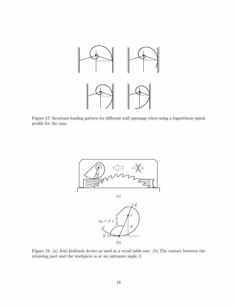
Figure 17: Invariant loading pattern for different wall openings when using a logarithmic spiralprofile for the cam.
(a)
(b)
Figure 18: (a) Anti kickback device as used in a wood table saw. (b) The contact between theretaining part and the workpiece is at an optimum angle β.
18

thickness of the workpiece, we can use the grasp invariance principle to design the shape of thedevice. The center of rotation lies on top of the contact line L and consequently the optimalsolution is a logarithmic spiral, with α0 = β + π
2 , as shown in Figure 21. The patent of thedevice [2] proposed a logarithmic spiral as the optimal contour.
Figure 19: Invariant contact geometry for different workpiece thicknesses when using a loga-rithmic spiral from for the anti kickback device.
6.3 Jar Wrench
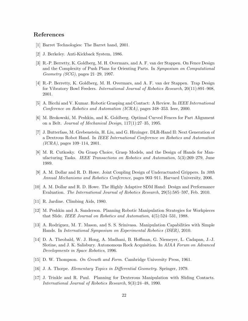
The jar wrench in Figure 2b opens jars of varying sizes. Figure 20a shows the basic operatingprinciple. The lid contacts the inner disk and the outer contour at different places for differentsized lids. The mechanics of the opening procedure, and specifically the amount of frictionavailable, depends of the value of the angle β.
If we know the optimal value of β, and want the mechanics to be invariant across the rangeof jar lid sizes, we can use the grasp invariance principle to design the contour. To simplify theanalysis we suppose, as shown in Figure 20b, that the lids are fixed and resting always againstthe same contact point, while the wrench rotates to contact the lid. The center of rotation ison top of the contact line L, consequently the optimal shape of the jar wrench is a logarithmicspiral, with α0 = π
2 − β.
7 Discussion
In this paper we introduce the grasp invariance principle and provide a recipe to apply it tothe design of rotating fingers and fixtures. Given a continuum of shape or pose variation and a
19
(a)
(b)
Figure 20: (a) Jar wrench. (b) Simplified diagram where the discs are fixed and the wrenchrotates.
Figure 21: Invariant contact geometry for different sized lids.
property to be held invariant we derive an optimal shape that satisfies the property across thecontinuum. We have shown that, in simple cases, the finger has a spiral form, and have appliedthe technique to design scale-invariant and pose-invariant grippers for disks and a pick-up tool.Finally we have analyzed the shape of a few common devices under the principle.
20

There are lots of extensions, generalizations and applications that we wish to explore. Herewe mention a few of them:
• Open design questions: Where should we put the center of rotation c? How do we choosethe transformation H(t, s)? The finger shape depends both on c and H(t, s). Thoseparameters can be chosen to satisfy additional properties. Specially we are interestedin the possibility of optimizing the location of c so as to avoid the interpenetrationconstraints mentioned in Section 3.3.
• This paper covers design issues of rotating and prismatic fingers. There are other typesof finger motion worth considering, for example those involving linkages.
• 2D designs are readily adapted to design grasp invariant 3D grippers, for example byarranging three fingers symmetrically around a circular palm. However we can alsothink about a deeper 3D generalization where the contact vector becomes the contacthyperplane and fingers become 2D surfaces.
• What happens when we deal with non-smooth boundaries? Can we extend the approachto include contact at vertices?
• The grasp invariance principle applies to one-dimensional variations of shape or pose ofthe object, e.g. scale-invariant or pose-invariant grippers. How can we trade off variousobjectives to address generalization across objects and tasks?
• Grasp invariance is both a principle and a method. The same method in Section 3.2can also be applied to synthesize grasp variance, where different objects are graspeddifferently.
• In this paper we have focused on the design of fingers, however the same principle can beapplied to the design of feet. Curved shaped feet have the potential to provide robustnesswith respect to variations in the terrain.
Acknowledgments
We wish to thank Garth Zeglin, Siddhartha Srinivasa, Amir Degani, Ross Knepper and TomasSimon for discussions, comments and insights.
21
References
[1] Barret Technologies: The Barret hand, 2001.
[2] J. Berkeley. Anti-Kickback System, 1986.
[3] R.-P. Berretty, K. Goldberg, M. H. Overmars, and A. F. van der Stappen. On Fence Designand the Complexity of Push Plans for Orienting Parts. In Symposium on ComputationalGeometry (SCG), pages 21–29, 1997.
[4] R.-P. Berretty, K. Goldberg, M. H. Overmars, and A. F. van der Stappen. Trap Designfor Vibratory Bowl Feeders. International Journal of Robotics Research, 20(11):891–908,2001.
[5] A. Bicchi and V. Kumar. Robotic Grasping and Contact: A Review. In IEEE InternationalConference on Robotics and Automation (ICRA), pages 348–353. Ieee, 2000.
[6] M. Brokowski, M. Peshkin, and K. Goldberg. Optimal Curved Fences for Part Alignmenton a Belt. Journal of Mechanical Design, 117(1):27–35, 1995.
[7] J. Butterfass, M. Grebenstein, H. Liu, and G. Hirzinger. DLR-Hand II: Next Generation ofa Dextrous Robot Hand. In IEEE International Conference on Robotics and Automation(ICRA), pages 109–114, 2001.
[8] M. R. Cutkosky. On Grasp Choice, Grasp Models, and the Design of Hands for Man-ufacturing Tasks. IEEE Transactions on Robotics and Automation, 5(3):269–279, June1989.
[9] A. M. Dollar and R. D. Howe. Joint Coupling Design of Underactuated Grippers. In 30thAnnual Mechanisms and Robotics Conference, pages 903–911. Harvard University, 2006.
[10] A. M. Dollar and R. D. Howe. The Highly Adaptive SDM Hand: Design and PerformanceEvaluation. The International Journal of Robotics Research, 29(5):585–597, Feb. 2010.
[11] R. Jardine. Climbing Aids, 1980.
[12] M. Peshkin and A. Sanderson. Planning Robotic Manipulation Strategies for Workpiecesthat Slide. IEEE Journal on Robotics and Automation, 4(5):524–531, 1988.
[13] A. Rodriguez, M. T. Mason, and S. S. Srinivasa. Manipulation Capabilities with SimpleHands. In International Symposium on Experimental Robotics (ISER), 2010.
[14] D. A. Theobald, W. J. Hong, A. Madhani, B. Hoffman, G. Niemeyer, L. Cadapan, J.-J.Slotine, and J. K. Salisbury. Autonomous Rock Acquisition. In AIAA Forum on AdvancedDevelopments in Space Robotics, 1996.
[15] D. W. Thompson. On Growth and Form. Cambridge University Press, 1961.
[16] J. A. Thorpe. Elementary Topics in Differential Geometry. Springer, 1979.
[17] J. Trinkle and R. Paul. Planning for Dexterous Manipulation with Sliding Contacts.International Journal of Robotics Research, 9(3):24–48, 1990.
22
[18] N. T. Ulrich. Grasping with Mechanical Intelligence, 1989.
[19] N. T. Ulrich, R. Paul, and R. Bajcsy. A Medium-Complexity Compliant End Effector.In IEEE International Conference on Robotics and Automation (ICRA), pages 434–436,1988.
[20] D. E. Whitney, R. E. Gustavson, and M. P. Hennessey. Designing Chamfers. InternationalJournal of Robotics Research, 2(4):3–18, 1983.
[21] J. Wiegley, K. Goldberg, M. Peshkin, and M. Brokowski. A Complete Algorithm forDesigning Passive Fences to Orient Parts. Assembly Automation, 17(2):129–136, 1997.
[22] M. T. Zhang and K. Goldberg. Gripper Point Contacts for Part Alignment. IEEE Trans-actions on Robotics and Automation, 18(6):902–910, Dec. 2002.
23