gravel roads construction and maintenance guide
TRANSCRIPT

Reconstruction Using a Detour When the reconstruction and resulting berm are significant, the work
space takes all or most of the road surface, leaving no room for traffic to negotiate past the work activities.
7
An agency may need to reconstruct the unpaved roadway
by correcting the drainage and/or adding surface materials.
With this type of work, additional equipment may be used
and a large amount of material may create a large berm
(12 inches or more across). This will present significant
hazards for the traveling public. To improve safety for mo
torists and workers, a detour may be the best TTC. Not all
road users will be familiar with the local road system and
some may be confused by the road closure, so signing
should be used to assist users negotiating the detour.
Reconstruction work space. (Source: Greg Vavra, SDLTAP).
Figure 4. TTC application for reconstruction using a detour.
Notes:1. Not all local agencies use route makers for
their system. MUTCD Section 6F.59 states
“A Street Name sign should be placed above,
or the street name should be incorporated
into, a DETOUR (M49) sign to indicate the
name of the street being detoured.”
2. With an increase in traffic at the intersections
where the detour begins and ends, a review
of the usage of the STOP and YIELD signs
should be completed.
3. Flashing warning lights and/or flags may be
used to call attention to advance warning
signs.
4. Flashing warning lights may be used on the
Type 3 Barricades, which should be installed
at the point where the road is closed.
5. For more complex TTC signing situations,
technical assistance can be obtained from
the local LTAP/TTAP or State DOT.
Errata Replaces page 137

GRAVEL ROADSGRAVEL ROADS
MAINTENANCEMAINTENANCE GUIDEGUIDE
CONSTRUCTION &CONSTRUCTION &
August 2015August 2015

AcknowledgementsThe original “Gravel Roads Maintenance and Design Manual” was published in 2000. It became an invaluable resource for managing gravel surfaced roads throughout the Nation and in other parts of the world. As in all fields, change occurs and resources need to be updated.
This revised manual has been produced as a joint effort by the Federal Highway Administration (FHWA) and the South Dakota Local Technical Assistance Program (SDLTAP) located at South Dakota State University in Brookings, SD. New information was gathered from local agencies across the United States and from other countries. In addition, current photographs have been included to this update.
Acknowledgment and appreciation is extended to the technical review committee, which helped guide this revised manual.
Advisory Panel Members:
Mark Sandifer – Advisory Panel Chair, FHWA Technology Partnership Programs Rafiq Darji – FHWA Florida Division Office
Hamilton Duncan – FHWA West Virginia Division Office Megan Chatfiel – FHWA Western Federal Lands Division Office
Jason Harrington - FHWA Office of InfrastructureBernie Kuta – FHWA Resource Center
Roger Surdahl – FHWA Central Federal Lands Division Office Deborah Vocke – FHWA Office of Public Affairs
Contributors:Ken Skorseth, Program Manager, South Dakota Local Technical Assistance Program (SDLTAP) Richard Reid, Ph.D., P.E., Associate Dean, Lohr College of Engineering, Director of SDLTAP Katherine Heiberger, Program Assistant at the SD Jerome J. Lohr College of Engineering, South Dakota State University, provided support for update text and photos for the manual.
Photos:Source of photos used on front and back cover, and pages 44, 56, and 86: istockphoto.com Permission to use all other photos throughout and printed herein, provided by their source: Ken Skorseth, Program Manager, SDLTAP
Notice: This document is disseminated under the sponsorship of the U.S. Department of Transportation in the interest of information exchange. The United States government assumes no liability for its contents or use thereof. This publication does not constitute a national standard, specification or regulation.
ii

GRAVEL ROADSCONSTRUCTION &CONSTRUCTION &
MAINTENANCE MAINTENANCE GUIDEGUIDE

Gravel Roads Construction and Maintenance Guideiv
List of Acronyms
AASHTO AADT ADT ASTM DEP DOT EPA FHWA LL LTAP MR MUTCD PI PCF PL PSI ROW SDLTAP TTAP
American Association of State Highway and Transportation Official Average Annual Daily TrafficAverage Daily TrafficAmerican Society of Testing and MaterialsDepartment of Environmental Protection Department of TransportationEnvironmental Protection AgencyFederal Highway AdministrationLiquid LimitLocal Technical Assistance ProgramResilient ModulusManual on Uniform Traffic Control DevicePlasticity Index = LL – PLPounds per cubic footPlastic LimitPounds per square inchRight-of-WaySouth Dakota Local Technical Assistance ProgramTribal Technical Assistance Program
Gravel Roads Construction and Maintenance Guide v
Table of ContentsSubject Page
Acknowledgements..................................................................................................iiList of Acronyms .....................................................................................................ivTable of Contents .....................................................................................................vForeward............................................................................................................... viiiIntroduction .............................................................................................................ixDefinition of Terms ...................................................................................................x
Section 1: Routine Maintenance & Rehabilitation 11.1 Understanding the Gravel Road Cross Section ...........................11.2 Routine Shaping Principles .........................................................51.3 Operating Speed .........................................................................61.4 Moldboard Angle .........................................................................61.5 Moldboard Pitch ..........................................................................71.6 Motorgrader Stability ...................................................................91.7 Articulation ..................................................................................91.8 Windrows .................................................................................101.9 Crown ........................................................................................ 111.10 Road Shoulder ..........................................................................151.11 High Shoulders (Secondary Ditches) ........................................171.12 Causes of High Shoulders ........................................................181.13 Recovering and Spreading on Roadway ..................................191.14 Breaking up Sod and Vegetation in Recovered Material ..........201.15 Pulling Shoulders and Removing Material .................................221.16 Benefit of Mowing .....................................................................231.17 Gravel Road Rehabilitation ......................................................241.18 Reshaping Surface and Shoulder .............................................251.19 Reshaping Entire Cross Section ...............................................261.20 Erosion Control .........................................................................271.21 Areas of Crown .........................................................................281.22 Dealing with Corrugation ...........................................................281.23 Intersections ..............................................................................311.24 Intersection with Paved Roads .................................................321.25 Bridge Approaches ....................................................................331.26 Superelevation in Curves ..........................................................341.27 Rail Crossings ...........................................................................351.28 Driveways .................................................................................361.29 Cattle Guards ............................................................................371.30 Soft and Weak Subgrades .........................................................38
Section 2: Drainage 452.1 Introduction........................................................................452.2 Ditches .............................................................................482.3 Culverts and Bridges ........................................................502.4 Underdrains ......................................................................54

Table of Contents Subject Page
Section III: Surface Gravel 573.1 What is Good Gravel? .................................................................573.2 Difference in Surface Gravel and Other Uses ..............................583.3 Good Gradation ...........................................................................583.4 Benefit of Crushing ......................................................................593.5 Recycled Asphalt .........................................................................593.6 The Benefit of Testing Aggregates ...............................................603.7 Reasons for Testing ......................................................................623.8 Sampling ......................................................................................623.9 Sieve Analysis ..............................................................................623.10 Fines and Plasticity Index ............................................................643.11 Reduced Blading and Maintenance Costs ...................................643.12 Process for Obtaining Good Gravel .............................................663.13 Establish Specifications ...............................................................673.14 Communicate with Suppliers .......................................................673.15 Handling Gravel ...........................................................................673.16 Pit/Quarry Operations ..................................................................683.17 Loading from Stockpiles ..............................................................703.18 Roadway Preparation ..................................................................713.19 Calculating Quantity .....................................................................713.20 Hauling and Dumping ..................................................................723.21 Windrowing, Equalizing and Spreading .......................................73
Section IV: Dust Control/Stabilization 754.1 Introduction ...................................................................................754.2 Types of Stabilizers ........................................................................76
4.2.1 Chlorides .........................................................................774.2.2 Resins ..............................................................................774.2.3 Natural Clays ...................................................................774.2.4 Petroleum Oils ..................................................................784.2.5 Portland Cement ...............................................................784.2.6 Organic Nonpetroleum Oil ................................................784.2.7 Other Commercial Binders ..............................................78
4.3 Benefits of Stabilization .................................................................794.4 Reduced Dusting .........................................................................794.5 Reduced Gravel Loss ....................................................................794.6 Reduced Blade Maintenance ........................................................794.7 Application Tips .........................................................................804.8 Need for Good Surface Gravel .....................................................804.9 Road Preparation .........................................................................804.10 Optimum Moisture .........................................................................814.11 Applying the Product .....................................................................824.12 Test Sections ..................................................................................844.13 Desired Performance .....................................................................84
vi
Table of Contents Subject Page
Section V: Innovations 875.1 Changes in Gravel Maintenance ................................................... 87 5.2 Changing Conditions – Equipment, Trucks, Cars ......................... 87 5.3 New Innovations ........................................................................... 88 5.4 Innovative Equipment and Methods .............................................. 89 5.5 Shoulder Disks ............................................................................... 905.6 Windrow Pulverizers ..................................................................... 905.7 Moldboard Cutting Edge Options .................................................. 935.8 Grader-Mounted Mixers ................................................................ 955.9 Grader-Mounted Roller ................................................................. 965.10 Electronic Slope Controls ............................................................... 975.11 Tractor-Mounted or Towed Blading Devices ................................. 985.12 Tractor-Mounted Crushers ........................................................... 100
Summary 101
Tools: 102Figures, Tables, Charts ............................................................................ 102
Appendices:Appendix A: Gravel Road Thickness Design Methods.............................103Appendix B: Gradation and P.I. Determination.........................................109Appendix C: Quantity Calculations ..........................................................112Appendix D: When to Pave a Gravel Road ..............................................115Appendix E: Walk-around Grader Inspection ...........................................124Appendix F: Temporary Traffic Control For Work Zones .........................128
on Unpaved Roads
vii
Gravel Roads Construction and Maintenance Guide
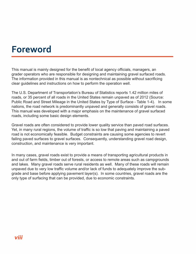
Foreword
This manual is mainly designed for the benefit of local agency officials, managers, angrader operators who are responsible for designing and maintaining gravel surfaced roads. The information provided in this manual is as nontechnical as possible without sacrificing clear guidelines and instructions on how to perform the operation well.
The U.S. Department of Transportation’s Bureau of Statistics reports 1.42 million miles of roads, or 35 percent of all roads in the United States remain unpaved as of 2012 (Source: Public Road and Street Mileage in the United States by Type of Surface - Table 1-4). In some nations, the road network is predominantly unpaved and generally consists of gravel roads. This manual was developed with a major emphasis on the maintenance of gravel surfaced roads, including some basic design elements.
Gravel roads are often considered to provide lower quality service than paved road surfaces. Yet, in many rural regions, the volume of traffic is so low that paving and maintaining a paved road is not economically feasible. Budget constraints are causing some agencies to revert failing paved surfaces to gravel surfaces. Consequently, understanding gravel road design, construction, and maintenance is very important.
In many cases, gravel roads exist to provide a means of transporting agricultural products in and out of farm fields, timber out of forests, or access to remote areas such as campgrounds and lakes. Many gravel roads serve rural residents as well. Many of these roads will remain unpaved due to very low traffic volume and/or lack of funds to adequately improve the sub-grade and base before applying pavement layer(s). In some countries, gravel roads are the only type of surfacing that can be provided, due to economic constraints.
viii

Introduction
Good gravel road maintenance or rehabilitation depends on two basic principles: proper use of a motorgrader (or other grading device) and use of good surface gravel. The use of the grader to properly shape the road is obvious to almost everyone, but the quality, volume, and size distribution of gravel needed is not as well understood. It seems that most gravel mainte-nance or rehabilitation problems are blamed on the grader operator when the actual problem is often material related. This is particularly true when dealing with the problem of corrugation or “washboarding” as it is often called in the field. This problem is often perceived as being caused by the grader, but it is primarily caused by the material itself. This manual provides information on what makes a good gravel road surface.
Another important matter to consider is the dramatic change in the vehicles and equipment using low volume roads. Tire pressures have increased to accommodate an ever expanding fleet of commercial trucks and agricultural equipment increasing in size, weight, and horse-power. The damaging effect of larger and heavier vehicles on our paved roads is well under-stood and requires the construction of stronger bases and pavements. But, the effect of these vehicles on gravel roads is just as serious and it is often not recognized. The strength of the subgrade and depth of the material needed to carry today’s heavy loads must be considered, along with proper drainage. For these reasons, sections of this manual are focused on construction, drainage, surface gravel, and stabilization of these roads.
The final section of the manual covers innovations in the gravel road maintenance and rehabilitation industry. Change is constant in almost every aspect of this modern world and new and different methods of maintaining gravel roads is no exception. There are new ways of stabilizing roads, new methods of dust control, and different kinds of equipment available for maintenance or rehabilitation of gravel roads. Alternative surface materials such as recycled pavement or blends of recycled and virgin aggregate are being used. Not all of these innovations may be available or practical for every local agency, but everyone is encouraged to take an objective look at each alternative. Then, an informed decision can be made about changing the way gravel roads are designed and maintained within their particular jurisdiction. Appendix A provides brief, basic guidance on construction or reconstruction of gravel roads.
ix
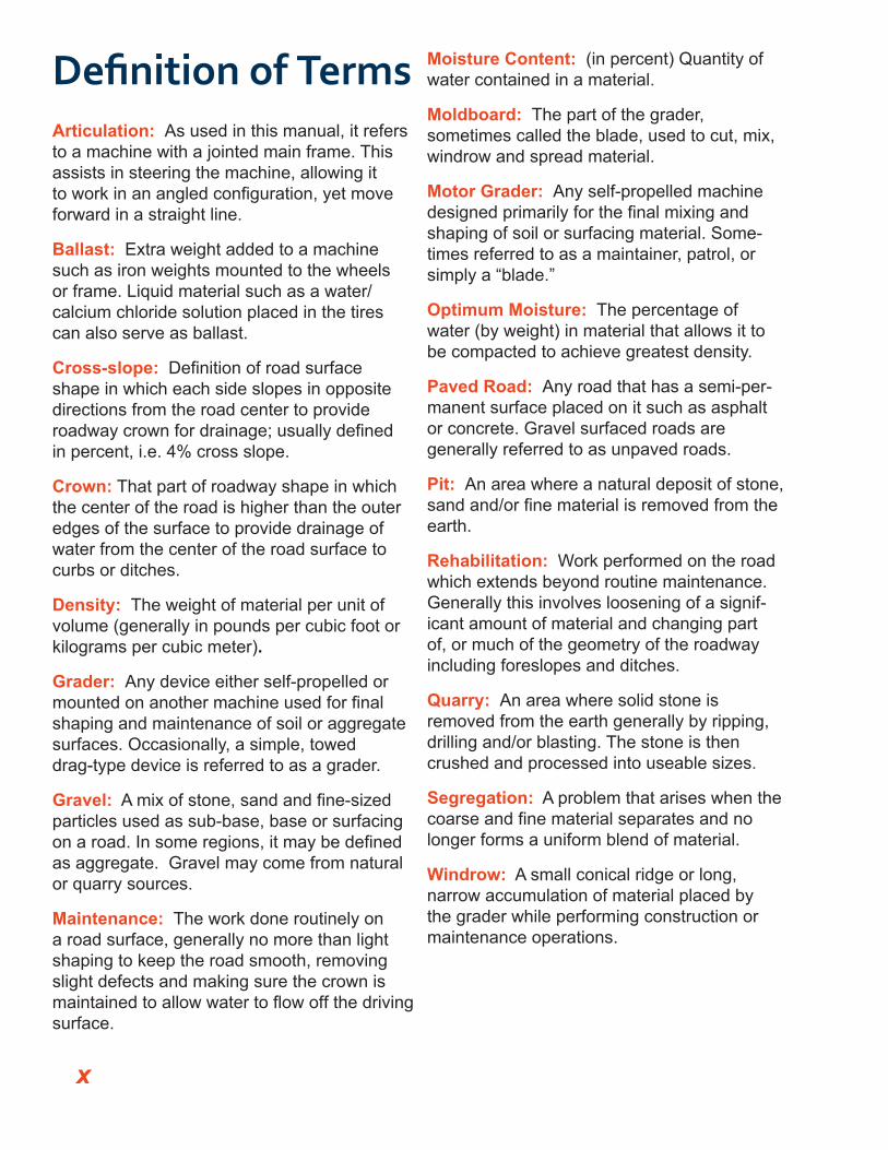
Definition of Terms Articulation: As used in this manual, it refers to a machine with a jointed main frame. This assists in steering the machine, allowing it to work in an angled configuration, yet move forward in a straight line.
Ballast: Extra weight added to a machine such as iron weights mounted to the wheels or frame. Liquid material such as a water/calcium chloride solution placed in the tires can also serve as ballast.
Cross-slope: Definition of road surface shape in which each side slopes in opposite directions from the road center to provide roadway crown for drainage; usually defined in percent, i.e. 4% cross slope.
Crown: That part of roadway shape in which the center of the road is higher than the outer edges of the surface to provide drainage of water from the center of the road surface to curbs or ditches.
Density: The weight of material per unit of volume (generally in pounds per cubic foot or kilograms per cubic meter).
Grader: Any device either self-propelled or mounted on another machine used for final shaping and maintenance of soil or aggregate surfaces. Occasionally, a simple, towed drag-type device is referred to as a grader.
Gravel: A mix of stone, sand and fine-sized particles used as sub-base, base or surfacing on a road. In some regions, it may be defined as aggregate. Gravel may come from natural or quarry sources.
Maintenance: The work done routinely on a road surface, generally no more than light shaping to keep the road smooth, removing slight defects and making sure the crown is maintained to allow water to flow off the driving surface.
Moisture Content: (in percent) Quantity of water contained in a material.
Moldboard: The part of the grader, sometimes called the blade, used to cut, mix, windrow and spread material.
Motor Grader: Any self-propelled machine designed primarily for the final mixing andshaping of soil or surfacing material. Some-times referred to as a maintainer, patrol, or simply a “blade.”
Optimum Moisture: The percentage of water (by weight) in material that allows it to be compacted to achieve greatest density.
Paved Road: Any road that has a semi-per-manent surface placed on it such as asphalt or concrete. Gravel surfaced roads are generally referred to as unpaved roads.
Pit: An area where a natural deposit of stone, sand and/or fine material is removed from theearth.
Rehabilitation: Work performed on the road which extends beyond routine maintenance. Generally this involves loosening of a signif-icant amount of material and changing part of, or much of the geometry of the roadway including foreslopes and ditches.
Quarry: An area where solid stone is removed from the earth generally by ripping, drilling and/or blasting. The stone is then crushed and processed into useable sizes.
Segregation: A problem that arises when the coarse and fine material separates and nolonger forms a uniform blend of material.
Windrow: A small conical ridge or long, narrow accumulation of material placed by the grader while performing construction or maintenance operations.
x

Section I: Routine Maintenance
and Rehabilitation1.1: Understanding the Gravel Road Cross SectionEveryone involved in gravel road maintenance must understand the correct shape of the entire area within the road’s right-of-way. Figure 1 shows a typical cross section of a gravel road. If States have minimum standards or policies for low-volume roads, they must be followed.
FIGURE 1: Roadway cross section. The components of the roadway cross section
In order to maintain a gravel road properly, operators must clearly understand the need for three basic elements:
1. A crowned driving surface,2. A shoulder area that slopes directly away from the edge of the driving surface, and3. A ditch.
The space for the shoulder area and the ditch of many gravel roads is often minimal. This is particularly true in regions with very narrow or confined rights-of-way. Regardless of the location, the basic shape of the cross section must be correct or a gravel road will not perform well, even under very low traffic.
1Gravel Roads Construction & Maintenance Guide
Gravel Roads Construction & Maintenance Guide
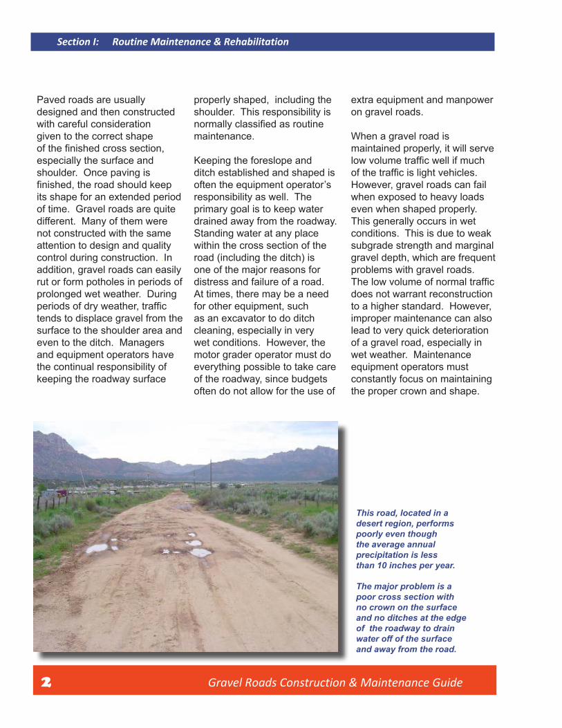
Paved roads are usually properly shaped, including the extra equipment and manpower designed and then constructed shoulder. This responsibility is on gravel roads.with careful consideration normally classified as routinegiven to the correct shape maintenance. When a gravel road is of the finished cross section, maintained properly, it will serve especially the surface and Keeping the foreslope and low volume traffic well if muchshoulder. Once paving is ditch established and shaped is of the traffic is light vehicles. finished, the road should keep often the equipment operator’s However, gravel roads can fail its shape for an extended period responsibility as well. The when exposed to heavy loads of time. Gravel roads are quite primary goal is to keep water even when shaped properly. different. Many of them were drained away from the roadway. This generally occurs in wet not constructed with the same Standing water at any place conditions. This is due to weak attention to design and quality within the cross section of the subgrade strength and marginal control during construction. .In road (including the ditch) is gravel depth, which are frequent addition, gravel roads can easily one of the major reasons for problems with gravel roads. rut or form potholes in periods of distress and failure of a road. The low volume of normal trafficprolonged wet weather. During At times, there may be a need does not warrant reconstruction periods of dry weather, traffic for other equipment, such to a higher standard. However, tends to displace gravel from the as an excavator to do ditch improper maintenance can also surface to the shoulder area and cleaning, especially in very lead to very quick deterioration even to the ditch. Managers wet conditions. However, the of a gravel road, especially in and equipment operators have motor grader operator must do wet weather. Maintenance the continual responsibility of everything possible to take care equipment operators must keeping the roadway surface of the roadway, since budgets constantly focus on maintaining
often do not allow for the use of the proper crown and shape.
This road, located in a desert region, performs poorly even though the average annual precipitation is less than 10 inches per year.
The major problem is apoor cross section with no crown on the surface and no ditches at the edge of the roadway to drain water off of the surface and away from the road.
2
Section I: Routine Maintenance & Rehabilitation
Gravel Roads Construction & Maintenance Guide 3
Section I: Routine Maintenance & Rehabilitation
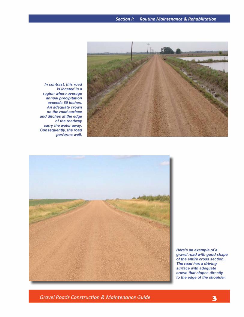
In contrast, this road is located in a
region where average annual precipitation exceeds 60 inches. An adequate crown on the road surface
and ditches at the edge of the roadway
carry the water away. Consequently, the road
performs well.
Here’s an example of a gravel road with good shape of the entire cross section. The road has a driving surface with adequate crown that slopes directly to the edge of the shoulder.

Gravel Roads Construction & Maintenance Guide 4
The foreslope of this road is also shaped very well,
which allows drainage of water from the road
surface down to the ditch.
This is another good example of roadway shape in an area with very limited right-of-way to maintain a road.
Section I: Routine Maintenance & Rehabilitation
Gravel Roads Construction & Maintenance Guide 5
Section I: Routine Maintenance & Rehabilitation
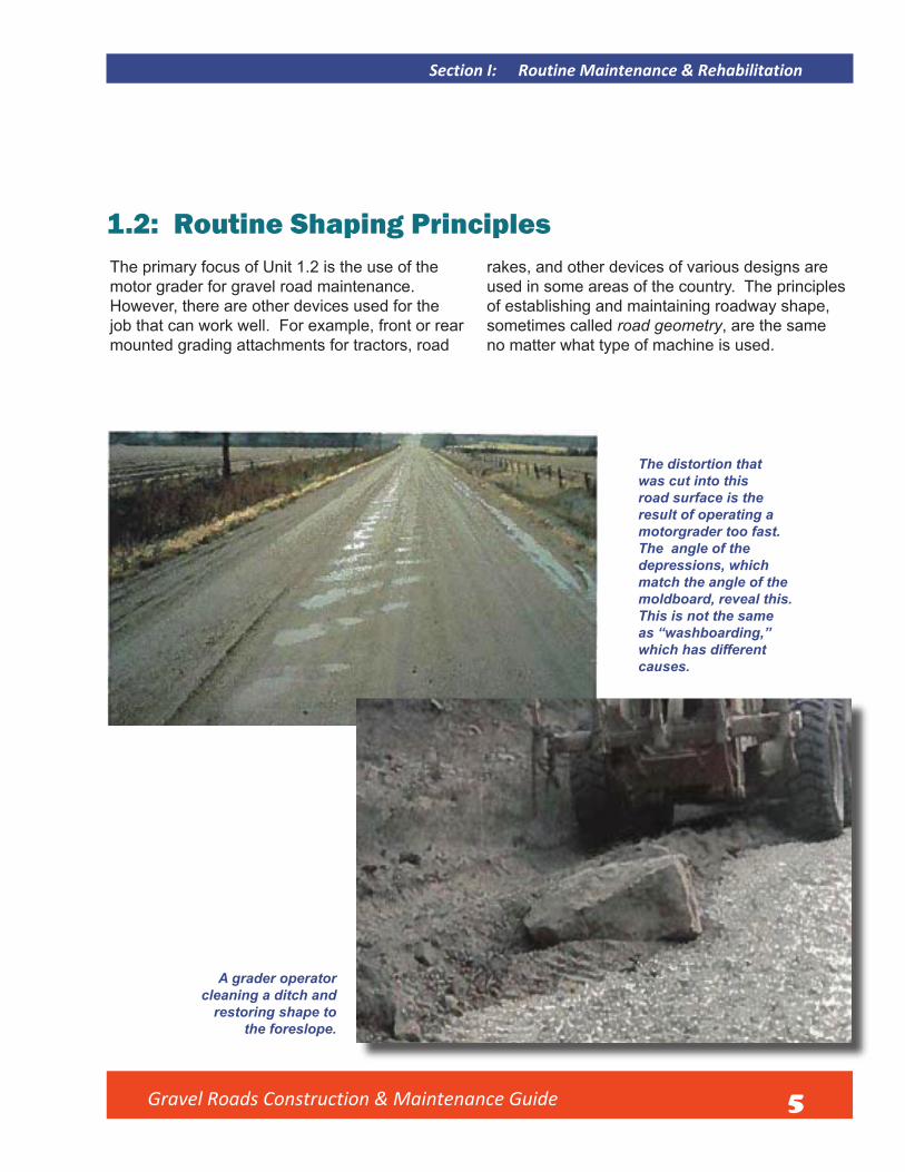
1.2: Routine Shaping PrinciplesThe primary focus of Unit 1.2 is the use of the motor grader for gravel road maintenance. However, there are other devices used for the job that can work well. For example, front or rear mounted grading attachments for tractors, road
rakes, and other devices of various designs are used in some areas of the country. The principles of establishing and maintaining roadway shape, sometimes called road geometry, are the same no matter what type of machine is used.
The distortion that was cut into this road surface is the result of operating a motorgrader too fast. The angle of the depressions, which match the angle of the moldboard, reveal this. This is not the same as “washboarding,” which has different causes.
A grader operator cleaning a ditch and
restoring shape to the foreslope.

Gravel Roads Construction & Maintenance Guide 6
1.3: Operating SpeedOperating speed in blading operations must not be excessive. It is virtually impossible to do good work above a top speed of 3 to 5 mph in most conditions. Higher speeds have caused problems on many roads. When the machine begins to “lope” or bounce, it will cut depressions and leave ridges in the road surface. Conditions including moisture, material quality, and subgrade stability vary; therefore, assigning a maximum speed for good maintenance is a challenge. Operating speed must be slow enough to be sure the machine remains stable.
1.4: Moldboard AngleThe angle of the moldboard is also critical for good maintenance. This angle is fixed on some gradingdevices, but on motor graders it can be easily adjusted. It is important to keep the angle somewhere between 30 and 45 degrees as illustrated in Figure 2. It is a challenge to recover loose aggregate from the shoulder of the roadway without spilling material around the leading edge (toe) of the moldboard. Operating without enough angle is a primary cause of this spilling not allow enough material to be carried for good maintenance.
Here’s a good example of using the angle and pitch of the moldboard to recover material and move it onto the roadway without spilling it around the toe of the moldboard.
No material is being lost since the angle is sufficient
to move material across the face of the moldboard.
Section I: Routine Maintenance & Rehabilitation

Gravel Roads Construction & Maintenance Guide 7
Section I: Routine Maintenance & Rehabilitation
FIGURE 2: Moldboard pitch. Moldboard pitch or “tilt” refers to how much the moldboard is tipped forward or backward.
The right pitch ranges from aggressive cutting (1), to spreading (2), to light blading or dragging action (3) for maintenance of gravel roads.
1.5: Moldboard PitchAlong with correct angle, it is important to understand proper pitch or “tilt” of a moldboard. If the moldboard is pitched back too far, the material will tend to build up in front of the moldboard and will not fall forward and move along to the discharge end, or heel, of the blade. This also causes excess material loss from the toe of the moldboard. It also reduces the mixing action that is desirable when recovering material from the shoulder and moving it across the roadway, leveling and smoothing it in the process. This mixing action is part of routine maintenance.
Trainer is demonstrating correct pitch of moldboard for most maintenance operations.

Gravel Roads Construction & Maintenance Guide 8
Some machines allow the moldboard
to be pitched forward too far for good maintenance
operations. Avoid extreme forward
pitch as shown here.
Here is the other extreme moldboard pitched too far back which simply pushes material and does not allow it to fall forward and move across the moldboard.
Traffic tends to loosen material from the roadsurface and displace it to the shoulder area as well as between the wheel tracks. The stone will tend to separate from the sand and the fine-sizedmaterial. At the same time, small potholes and an uneven surface will develop. It is the job of the maintenance operator to recover the material,
mix it again as it rolls along the face of the moldboard and restore good surface shape. On some machines, the moldboard may be pitched too far forward. It will accomplish little more than light dragging and does not allow enough material to be carried for good maintenance.
Section I: Routine Maintenance & Rehabilitation

Gravel Roads Construction & Maintenance Guide 9
Section I: Routine Maintenance & Rehabilitation
1.6: Motor Grader StabilityIt can sometimes be hard to keep a machine stable, especially while carrying a light load of material. Counteracting machine bounce or “loping” requires experience — knowing the cause and then finding a solution. If a motor grader begins to rock from side to side — often called “duck walking” in the field — it is usually caused by a blade angle that closely matches the angle from corner to corner of the tires on the rear tandem axles. The solution is generally to stop, change the moldboard angle slightly and slowly resume blading. Simply reducing speed will also often eliminate the loping effect of a machine.
Experimenting with different tire inflationpressures can help stabilize a machine, as well as leaning the front wheels in the direction that material is being moved. Adding extra weight at the front of the grader may also help. Filling tires with liquid ballast to about 70 percent capacity is sometimes done to increase traction, weight and stability of the grader. The ballast most often used is a solution of calcium chloride and water. Stability problems that are constant and severe should be brought to the attention of your equipment dealer and/or tire supplier.
FIGURE 3: Articulated Motorgrader Illustration of an articulated motor grader and definitions of terms specific to the moldboard.
1.7: ArticulationVirtually all modern motor graders are equipped with frame articulation. It can be an advantage to slightly articulate the machine to stabilize it even in a common maintenance operation. More aggressive articulation will allow a greater reach with the moldboard. For example, the front wheels can be placed out on the shoulder to better recover material with the moldboard while keeping the rear axles on the roadway for stability. There are too many applications for articulation to cover here, but operators should learn to use this feature to their advantage in both routine and rehabilitation operations.

Gravel Roads Construction & Maintenance Guide 10
1.8: WindrowsIn some areas, particularly arid or semi-arid regions, it is a commonly accepted practice to leave a small maintenance windrow near the edge of the roadway. This practice involves leaving a small amount of material to be picked up next time and worked back across the road for filling smalldepressions. In other places, it is disapproved of and departments may have policies forbidding windrows. This is often true in regions with narrow rights-of-way and narrow driving surfaces. Leaving windrows is often not allowed in areas of high rainfall due to restriction of drainage to the shoulder and ditch. Operators must know and follow applicable agency policy on windrows.
If leaving a maintenance windrow is allowed by policy, this is a good example of a light windrow being placed at the
edge of the roadway.
For those jurisdictions that allow the use of windrows, it is important to keep them to a minimum. The windrow should also be placed near the edge of the roadway to allow as great a width for travel as possible. It can be difficult to distinguishbetween inadequate and excessive windrows. In the absence of a policy on this matter, be aware of the commonly accepted practices in your region and perform work in a similar manner.
This windrow is excessive and should never be left on the roadway. It is a bad practice even on a very low volume road. Multiple passes should have been made with the grader to work the vegetation out of the windrow or other mechanical means such as a disk should have been used to break up the chunks of sod so more material could be spread on the roadway.
Section I: Routine Maintenance & Rehabilitation

Gravel Roads Construction & Maintenance Guide 11
Section I: Routine Maintenance & Rehabilitation
1.9: CrownEstablishing the proper crown in the gravel surface probably generates more controversythan any other aspect of good maintenance. How much crown is enough? Can one get too much? What is recommended crown? These are frequently asked questions by local officials,the traveling public, and equipment operators.
How much crown is enough? Problems develop quickly when a gravel road has no crown. A proper crown ensures water will drain off the roadway surface during a rain event. Without it, water will quickly collect on the road surface during a rain event or snow melt and will soften the crust. Water retained in the roadway surface can lead to rutting, which can extend down into the subgrade. Therefore, a properly drained gravel road must have a sufficient or adequatecrown.
Can one get too much? Too much crown in the road surface can lead to an unsafe condition. The traveling public may have difficulty staying “intheir lane.” Due to an excessive crown, drivers begin to feel a slight loss of control as their vehicle wants to slide towards the shoulder. There is also additional risk driving on gravel roads with an excessive crown in regions that experience snow and ice cover, which adds to the risk of sliding off the road. For these reasons, roads with excessive crowns will encourage road users to depart from their travel lane and drive in the middle of the road regardless of how wide the lane or roadway may be.
What then is the recommended crown? Supervisors and skilled operators across the country indicate that at, or near, 1/2 inch of crown per foot (approximately 4 percent) on the cross slope is highly recommended. While it is virtually impossible for any operator to maintain an absolutely uniform crown, minimal deviation is
recommended. It is not good to exceed 6 percent in any condition. Crown gauges are available that may be mounted in the grader cab to help the operator control crown. There are also electronic slope controls available for graders today. Slope controls are normally found in construction operations, but can be used for gravel road reshaping and maintenance applications.
This is a road that lacks adequate crown. Potholes and corrugation are also forming as a result of lack of a crown to drain water from the road surface.

Gravel Roads Construction & Maintenance Guide 12
A road that is wide (25 ft. surface width) yet
everyone drives in the middle. The primary reason is
excessive crown.
Narrow roads in confined right-of-waysstill must have crown or they will not perform well.
Section I: Routine Maintenance & Rehabilitation

Gravel Roads Construction & Maintenance Guide 13
Section I: Routine Maintenance & Rehabilitation
An additional problem with crown that needs to be discussed is called a parabolic crown. The ideal surface shape is a straight line from the shoulder up to the center of the road. This gives the road the same shape as the roof of a house, often referred to as a Straight A Shape.
However, this shape can sometimes become rounded. The engineering term for this rounding of the surface is parabolic crown, which is virtually always a problem. Why? The middle portion of the road will have considerably less crown than the outer edges. Water will not drain from the middle and potholes and ruts will form.
FIGURE 4: Roadway with a parabolic crown. The outer edge of the roadway slopes too much due to gouging at the edges
while the center of the road remains quite flat.
The greatest cause of a parabolic crown is excess wear at the center of the cutting edge. This is normal wear and will vary with types of gravel, width of road, wheel path location, and other factors. A good operator will make an effort to avoid creating parabolic shapes on a roadway by keeping the equipment’s cutting edge straight. To achieve this result, simply use a cutting torch and straighten the cutting edge whenever 1/2- to 3/4-inch or more of center wear exists. Another option is to use a thicker, harder section of cutting edge in the middle of the moldboard to resist wear. This will retard excess center wear, but generally will not eliminate it.
Gravel Roads Construction & Maintenance Guide 14
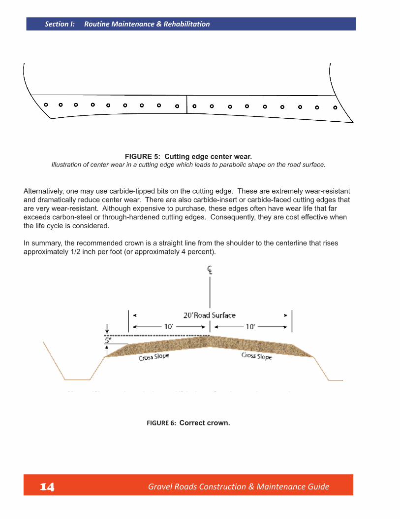
FIGURE 5: Cutting edge center wear.Illustration of center wear in a cutting edge which leads to parabolic shape on the road surface.
Alternatively, one may use carbide-tipped bits on the cutting edge. These are extremely wear-resistant and dramatically reduce center wear. There are also carbide-insert or carbide-faced cutting edges that are very wear-resistant. Although expensive to purchase, these edges often have wear life that far exceeds carbon-steel or through-hardened cutting edges. Consequently, they are cost effective when the life cycle is considered.
In summary, the recommended crown is a straight line from the shoulder to the centerline that rises approximately 1/2 inch per foot (or approximately 4 percent).
Note: 4% crown is equivelant to 1/2 inch per foot drop on the cross slope.
FIGURE 6: Correct crown.
Section I: Routine Maintenance & Rehabilitation

Gravel Roads Construction & Maintenance Guide 15
Section I: Routine Maintenance & Rehabilitation
This road performs remarkably well because of good crown and good gravel quality in a very wet region.
1.10: Road ShoulderThe road shoulder serves several essential functions. Primarily, it supports the edge of the traveled portion of the roadway. Another important function is to provide a safety area for drivers to regain control of vehicles, if forced to leave the road surface. The shoulder also plays an important role in drainage, carrying water further away from the road surface towards the foreslope and into the ditch.
In order for the shoulder to perform all of these functions, its shape is critical. First, the shoulder should meet the edge of the roadway at the same elevation. In other words, the shoulder should begin no higher or no lower than the edge of the
roadway. By maintaining this shape, the low shoulder (or drop-off), which is a safety hazard, is eliminated and improves roadway edge sup-port. But the other extreme, which is a high shoulder, should also be avoided, as it prevents proper drainage. This will be further explained in Sections 1.17, 1.18, and 1.19.
It is also recognized that gravel roads in some regions, particularly those with very narrow rights-of-way, have very little shoulder area. In some cases, the edge of roadway is actually the beginning of the foreslope down into the ditch. But again, it is important that there is not a steep drop-off or a ridge of soil to block drainage. Maintaining shoulders is a critical part of gravel road maintenance.

Gravel Roads Construction & Maintenance Guide 16
These photos (left and below) show good examples of gravel shoulders that match the edge of the roadway very well and drain water to the ditch.
Section I: Routine Maintenance & Rehabilitation
Gravel Roads Construction & Maintenance Guide 17
Section I: Routine Maintenance & Rehabilitation
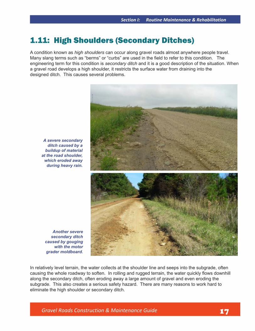
1.11: High Shoulders (Secondary Ditches)A condition known as high shoulders can occur along gravel roads almost anywhere people travel. Many slang terms such as “berms” or “curbs” are used in the field to refer to this condition. The engineering term for this condition is secondary ditch and it is a good description of the situation. When a gravel road develops a high shoulder, it restricts the surface water from draining into the designed ditch. This causes several problems.
A severe secondary ditch caused by a
buildup of material at the road shoulder,
which eroded away during heavy rain.
Another severe secondary ditch
caused by gouging with the motor
grader moldboard.
In relatively level terrain, the water collects at the shoulder line and seeps into the subgrade, often causing the whole roadway to soften. In rolling and rugged terrain, the water quickly flows downhillalong the secondary ditch, often eroding away a large amount of gravel and even eroding the subgrade. This also creates a serious safety hazard. There are many reasons to work hard to eliminate the high shoulder or secondary ditch.

Gravel Roads Construction & Maintenance Guide 18
What causes secondary ditches to form? There are several causes. They can develop from improper maintenance, such as losing material from the toe of a grader’s moldboard that builds up a high shoulder, or from cutting too deep at the shoulder line with the toe of the moldboard. This is a particular problem when the cutting edge is not kept reasonably straight.
But there are many other causes, for example, excessive “whip-off” of loose material from fast traffic, which tends to build up along the shoulderline. Also, heavy loads on gravel roads with weak subgrades can cause this scenario.
When heavy vehicles have to travel near the shoulder while meeting other vehicles, the roadway can rut while the shoulder area shoves upward. Yet another cause is the buildup of sand in northern regions where winter ice/snow control requires some winter sanding operations on gravel roads. An expert in the field once stated,“It is difficult to completely eliminate secondary ditches, but it pays to work hard to keep them to an absolute minimum.” This is excellent advice. The time spent in eliminating a high shoulder (secondary ditch) will result in a road that is easier to maintain afterwards.
A heavy haul, along with poor maintenance, has destroyed the shape of this road, as shown here during rain.
Obstruction of shoulder drainage is the biggest problem.
1.12: Causes of High Shoulders (Secondary Ditches)
Section I: Routine Maintenance & Rehabilitation

Gravel Roads Construction & Maintenance Guide 19
Section I: Routine Maintenance & Rehabilitation
1.13: Recovering and Spreading on Roadway
If a motor grader is the only piece of equipment used on the job, generally more than one pass will be required to recover material from high shoulders. This process is often referred to as pulling the shoulder.
Place appropriate temporary traffic control signsto warn road users--this is more than routine maintenance (See Appendix F). If there is little or no vegetation on the shoulder, simply extend the moldboard out into the shoulder material and begin to pull it onto the roadway.
If the amount of material is light, you may be able to do this in one pass. The material recovered is often good gravel that needs to be returned to the roadway surface.
Use of motor grader moldboard to recover loose material and
move it back on the roadway to restore shoulder drainage.

Gravel Roads Construction & Maintenance Guide 20
1.14: Breaking up Sod and Vegetation in Recovered MaterialQuite often, the material pulled out onto the roadway from the shoulder is very hard to spread because of the vegetative material it contains. Multiple passes with the grader will be required to get the job done. Many agencies are turning to other mechanical means of breaking up the material (from something as simple as a disk or drag to sophisticated pulverizing equipment) to make the road safe for traffic.
A shop fabricated disk mounted on a
grader (right) and a small disk mounted on a tractor (below).
These are good tools for breaking
up clumps in material recovered from the shoulder.
Section I: Routine Maintenance & Rehabilitation
Gravel Roads Construction & Maintenance Guide 21
Section I: Routine Maintenance & Rehabilitation
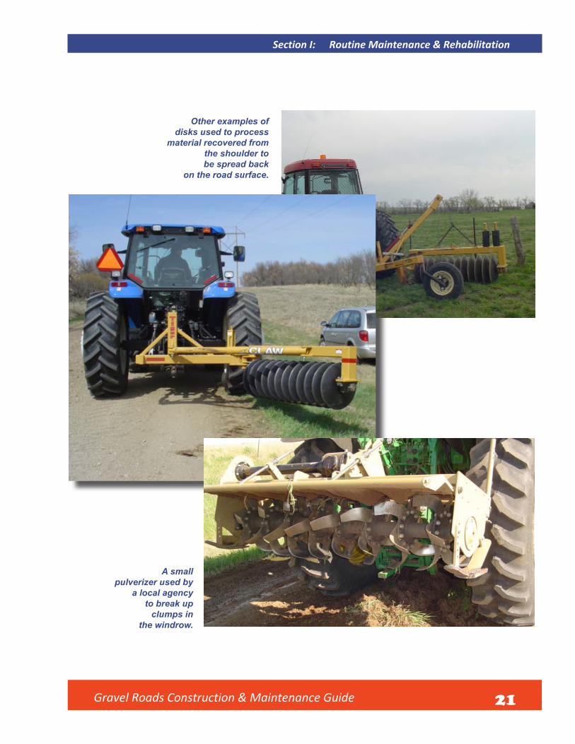
Other examples of disks used to process
material recovered from the shoulder to be spread back
on the road surface.
A small pulverizer used by
a local agency to break up
clumps in the windrow.
Gravel Roads Construction & Maintenance Guide 22
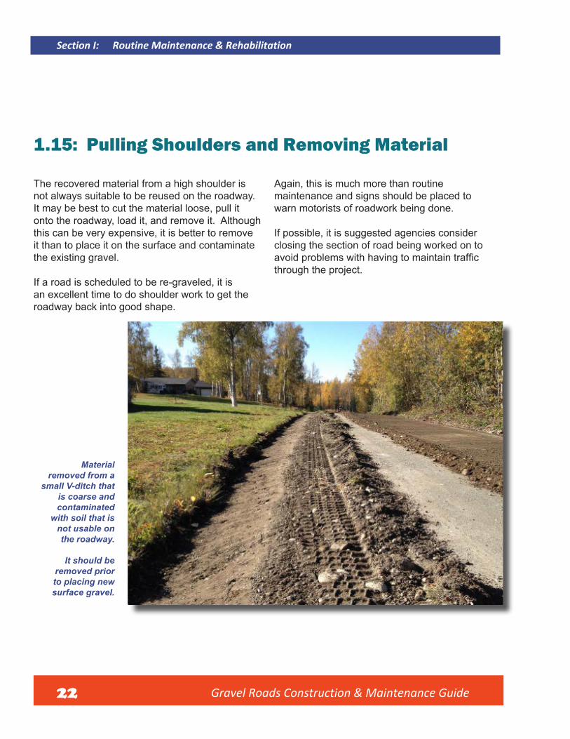
1.15: Pulling Shoulders and Removing Material
The recovered material from a high shoulder is not always suitable to be reused on the roadway. It may be best to cut the material loose, pull it onto the roadway, load it, and remove it. Although this can be very expensive, it is better to remove it than to place it on the surface and contaminate the existing gravel.
If a road is scheduled to be re-graveled, it is an excellent time to do shoulder work to get the roadway back into good shape.
Again, this is much more than routine maintenance and signs should be placed to warn motorists of roadwork being done.
If possible, it is suggested agencies consider closing the section of road being worked on to avoid problems with having to maintain trafficthrough the project.
Material removed from a
small V-ditch that is coarse and contaminated
with soil that is not usable on the roadway.
It should be removed prior to placing new surface gravel.
Section I: Routine Maintenance & Rehabilitation

Gravel Roads Construction & Maintenance Guide 23
Section I: Routine Maintenance & Rehabilitation
1.16: Benefits of MowingAny of the procedures discussed for dealing with high shoulders are much easier to accomplish if appropriate mowing is done in advance. This is true even in routine maintenance operations. When grass or other vegetation grows high along the edge of the roadway, it becomes difficult to maintain a clean, uniform shoulder line. A survey of operators in the State of Iowa indicated mowing the shoulders on gravel roads ranked as one of four primary functions needed to maintain a good gravel road. Keeping proper shape, drainage, and straight cutting edges were the others.
The frequency of mowing depends on the region of the country and the climate. However, the cost of mowing is often offset by reduced costs of other maintenance and safer roads. In northern plains regions, there is yet another great benefit of mowing; byremoving the standing vegetation, drifting snow will not be trapped on the roadway, resulting in drastically reduced snow removal costs. The best equipment for this work is rotary or flail mowers, which both do a goodjob of shredding the vegetation, and are not as easily damaged or plugged by roadside trash.
It is particularly important to cut back heavy vegetation like this just to make minor
improvement at the shoulder.
Notice the dramatic difference in the road shoulders, shown in these photos.
It becomes so much easier to recover gravel that has drifted to the edge of
the roadway when the vegetation has been cut cleanly.

Gravel Roads Construction & Maintenance Guide 24
1.17: Gravel Road Rehabilitation
A road section heavily damaged during a wind energy construction project in wet conditions.
Gravel roads are generally maintained by routine blading and adding gravel as needed either by “spot graveling” or re-graveling entire sections. However, almost any gravel road will gradually begin to show distress over time that requires more than routine maintenance to correct. The most common problems that develop are “berms” or secondary ditches that build up along the shoulder line and the shifting of material from the surface to the shoulder area and even onto the foreslope of the grade.
This comes from gravel being displaced by traffic,winter plowing operations, erosion of material during heavy rain, and sometimes from poor routine blading techniques. This scenario often
causes major problems with drainage. Frequent use by heavy trucks or equipment can also damage the cross section. At certain intervals, virtually every gravel road requires some major rehabilitation.
This involves reshaping not only the road surface, but the shoulder area and possibly the foreslope and ditch. This work may be accomplished with motor graders only depending on the extent of work needed to reestablish a good cross section on the roadway. Compaction equipment if available is always helpful. If material must be removed, loaders or excavators and trucks will be needed.
Section I: Routine Maintenance & Rehabilitation

Gravel Roads Construction & Maintenance Guide 25
Section I: Routine Maintenance & Rehabilitation
1.18: Reshaping Surface and Shoulder
Problems with surface and shoulder shape can usually be corrected with the motor grader alone. Spring is the best time for this work as there is minimal vegetative growth and moisture is often present. The reshaping of the driving surface and the road shoulder can be done by cutting material with the motor grader and relaying it to the proper shape and crown. If possible, the use of a roller for compaction will greatly improve the finishedsurface. This will leave a denser, stronger,
smoother surface that will be easier to maintain. Pneumatic (rubber tired) rollers are most often used for compaction of gravel. Sometimes these rollers are mounted on the motor grader. Smooth, steel drum rollers are sometimes used, but good surface gravel needs to have a cohesive or binding characteristic, and this type of material can easily stick to a steel roller making them hard to use, especially when moisture in the gravel is at or above optimum.
This is the same road as shown in the previous photo after complete surface and shoulder reshape and new surface gravel added. It performs well once again.
Gravel Roads Construction & Maintenance Guide 26
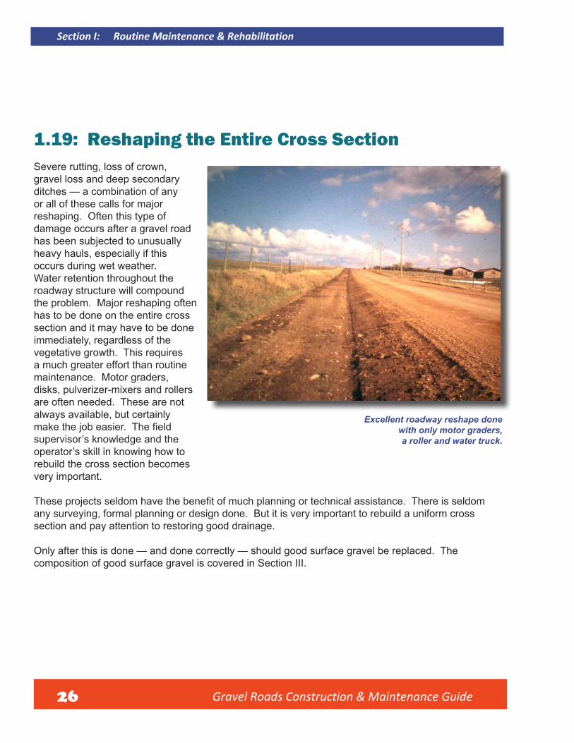
1.19: Reshaping the Entire Cross SectionSevere rutting, loss of crown, gravel loss and deep secondary ditches — a combination of any or all of these calls for major reshaping. Often this type of damage occurs after a gravel road has been subjected to unusually heavy hauls, especially if this occurs during wet weather. Water retention throughout the roadway structure will compound the problem. Major reshaping often has to be done on the entire cross section and it may have to be done immediately, regardless of the vegetative growth. This requires a much greater effort than routine maintenance. Motor graders, disks, pulverizer-mixers and rollers are often needed. These are not always available, but certainly make the job easier. The fieldsupervisor’s knowledge and the operator’s skill in knowing how to rebuild the cross section becomes very important.
These projects seldom have the benefit of much planning or technical assistance. There is seldom any surveying, formal planning or design done. But it is very important to rebuild a uniform cross section and pay attention to restoring good drainage.
Only after this is done — and done correctly — should good surface gravel be replaced. The composition of good surface gravel is covered in Section III.
Excellent roadway reshape done with only motor graders, a roller and water truck.
Section I: Routine Maintenance & Rehabilitation

Gravel Roads Construction & Maintenance Guide 27
Section I: Routine Maintenance & Rehabilitation
1.20: Erosion ControlHaving discussed the importance of reshaping a gravel road, there is another issue that must be addressed. When major reshaping is done outside the traveled way, vegetation and ground cover will obviously be disturbed. This can lead to the erosion of soil. This problem will vary depending on the region. For example, in arid and semi-arid areas, the problem may be small. Areas that receive frequent rains, have rolling or rugged terrain, and have highly erodible soils, are particularly vulnerable. When vegetative cover is disturbed, there are additional concerns. While trying to eliminate problems, new ones can be created, such as clogged culverts and blocked ditches, pollution of streams and lakes, and eroded slopes, which can shorten the life of improvements, damage the environment, and violate environmental regulations.
The solution to these issues is not to cancel plans for gravel road improvement, but to plan your work carefully and use established methods for reducing or eliminating erosion. Here are some things to consider:
• Pay attention to theseasons. Some regionshave certain times in theyear when frequent andheavy rainfall can beexpected. Try to avoidmajor reshape work duringthose time periods.
• Keep disturbed areas assmall as possible. Themore earth you disturb,the greater will be the riskof soil erosion. Set workboundaries and don’t letwork crews get outside of them.
• Consider stabilization of disturbed areas. Seeding, mulching, erosion control blankets andother methods as applicable can be used effectively.
• Keep water velocities low. Removing vegetative cover generally increases the volume andvelocity of water runoff. Keep slopes as shallow or gentle as possible. Keep ditch slope asgentle as possible. Shorten drainage runs and work to get vegetative cover re-established assoon as possible after work is finished
• Keep sediment within work boundaries. Sediment can be retained by filtering water as it flows(as through a silt fence), and ditch checks will retain dirty runoff water for a period of time untilparticles of sediment settle out.
• Inspect recent work. It is vital to make sure channels haven’t formed in ditch bottoms or onslopes, or around and under controls that were used. Be particularly vigilant after heavy rainevents.
Good example of basic erosion control after gravel road reshape.

Gravel Roads Construction & Maintenance Guide 28
1.21: Areas of ConcernThere are special situations in gravel road maintenance that should be addressed. These are common to nearly all gravel roads, and it is important to understand how to deal with them. These concerns are unique to gravel roads and practical solutions are recommended for each of them.
This type of corregation, “washboarding,” is caused by lack of moisture, hard acceleration, aggressive braking, and poor quality gravel.
1.22: Dealing with CorrugationThe technical term is corrugation, but virtually everyone in the field refers to the problem aswashboarding. This problem can bring more complaints than any other. It is very annoying to the driver and, when it becomes severe, can lead to loss of vehicle control.
This type of washboarding appears at an angle across
the roadway with ridges and depressions 2 to 3 feet apart.
It is caused by excess grader speed and lack of crown.
Section I: Routine Maintenance & Rehabilitation
Gravel Roads Construction & Maintenance Guide 29
Section I: Routine Maintenance & Rehabilitation
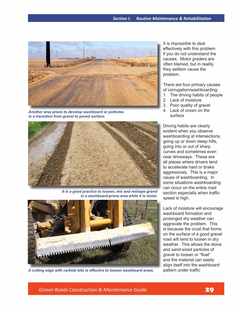
It is impossible to deal effectively with this problem if you do not understand the causes. Motor graders are often blamed, but in reality, they seldom cause the problem.
There are four primary causes of corrugation/washboarding: 1. The driving habits of people2. Lack of moisture3. Poor quality of gravel4. Lack of crown on the
surface
Driving habits are clearly evident when you observe washboarding at intersections, going up or down steep hills, going into or out of sharp curves and sometimes even near driveways. These are all places where drivers tend to accelerate hard or brake aggressively. This is a major cause of washboarding. In some situations washboarding can occur on the entire road section especially when trafficspeed is high.
Lack of moisture will encourage washboard formation and prolonged dry weather can aggravate the problem. This is because the crust that forms on the surface of a good gravel road will tend to loosen in dry weather. This allows the stone and sand-sized particles of gravel to loosen or “float”and the material can easily align itself into the washboard pattern under traffic
Another area prone to develop washboard or potholes is a transition from gravel to paved surface.
It is a good practice to loosen, mix and reshape gravel in a washboard-prone area while it is moist.
A cutting edge with carbide bits is effective to loosen washboard areas.
Gravel Roads Construction & Maintenance Guide 30
The two causes just mentioned are completely out of the control of equipment operators and managers. The third primary cause — the quality of the gravel — is the cause that needs special attention. Good quality surface gravel is thoroughly discussed in Section II of this manual. Simply put, good gravel must have the right blend of stone, sand, and fines. The stone should be fractured and the fine-sized particles should have a binding characteristic, technically called “plasticity.” This type of gravel resists washboarding and will reduce the problem significantly. Lack of crown is the fourth cause. If water cannot drain off of the travelled way and corrugation begins to form, the water will quickly accumulate in the depressions and soften that area of the surface. Traffic will then make the depressions deeper as tires strike the depressions and force aggregate out and up into greater ridges.
Virtually any gravel will develop some washboard areas under traffic. The key for the maintenance operator is to strive to keep the material blended. In dry conditions, the operator can only smooth the road temporarily. When moisture is present, it pays to quickly get out and rework these areas.
The material should be cut to a depth of 1 inch or more below the depressions, then mixed and relayed to the proper shape. If time allows, using
the machine to apply wheel compaction to the loosened material will help reform the crust. If possible, use a roller to improve the compaction.
With the best of maintenance, washboarding can never be completely eliminated. However, the key to reducing it is to work hard at obtaining quality gravel with a good binding characteristic. Another option is to test the existing surface gravel and add material on the roadway to modify it to a suitable gradation and plasticity. It must be thoroughly mixed with the motor grader. Thereafter, trouble spots can be reshaped when moisture is present and most roads will perform quite well with limited blade maintenance.
If a motor grader actually causes washboarding, it is almost always the result of running at too great a speed. The ridges and depressions will be spaced further apart and will form at the angle across the roadway at which the moldboard was set while doing maintenance. This is seldom the case since most washboards appear perpendicular to the direction of vehicle travel.
The solution to the problem is simple — reduce operating speed! Another problem can be improper tire inflation pressure or defective tires. This will cause a motor grader to bounce or otherwise operate in an unstable manner.
Section I: Routine Maintenance & Rehabilitation

1.23: Intersections
Gravel Roads Construction & Maintenance Guide 31
Section I: Routine Maintenance & Rehabilitation
There is one important thing to understand in knowing how to shape a gravel surfaced intersection: is it a controlled or uncontrolled intersection? This means: does traffic have to stop or yield from intersecting roads? If so, it is a controlled intersection as shown in Figure 7.
The primary road on which traffic passes through should retain its crown and the intersecting roads should have crown gradually eliminated beginning approximately 100 feet before the intersection.
At the point of intersection, the side roads are virtually flat to match the primary road. When the inter-section is uncontrolled, as shown in Figure 8, the roads should all have the crown gradually eliminated beginning approximately 100 feet from the intersection.
The intersection itself becomes virtually flat, allowing vehicles to pass through without feeling a noticeable bump or dip from any direction. Be careful not to make the intersection lower so that water collects there.
FIGURE 7: Proper shape of a
controlled intersection. Notice through-road retains
crown; side roads which have no stop or yield signs are shaped to match the
edge of through-road.
FIGURE 8: Proper shape of an
uncontrolled intersection. Eliminate crown from all directions approaching
the intersection.

Gravel Roads Construction & Maintenance Guide 32
1.24: Intersections with Paved RoadsThe rule for shaping these intersections is always the same. Begin to eliminate crown on the gravel road approximately 100 feet from the edge of the pavement.
At the intersecting point, the gravel should match the paved surface. This requires continual attention since potholes can easily develop at the edge of pavement.
When potholes become severe, the gravel needs to be cut out and relayed to correct the problem. However, be careful not to push gravel out onto the pavement since this causes a dangerous loss of skid resistance on the pavement. The technique of “backdragging” is useful in these operations. In order to cut out and fill a pothole at the edgeof pavement, extra material may spill onto the pavement. Simply pick up the moldboard and set it down in front of the material, then back up and spread the excess back on the gravel road.
FIGURE 9: Illustration of a gravel road intersecting a paved road. Gradually, eliminate the crown
on the gravel road to match the edge of pavement.
Eliminate the Crown
A well-shaped intersection of
gravel surface and paved road.
Section I: Routine Maintenance & Rehabilitation
Gravel Roads Construction & Maintenance Guide 33
Section I: Routine Maintenance & Rehabilitation
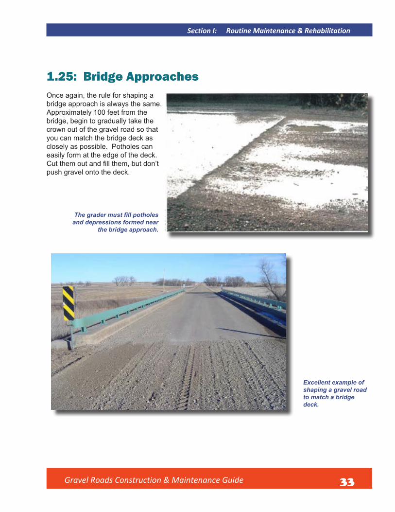
1.25: Bridge ApproachesOnce again, the rule for shaping a bridge approach is always the same. Approximately 100 feet from the bridge, begin to gradually take the crown out of the gravel road so that you can match the bridge deck as closely as possible. Potholes can easily form at the edge of the deck. Cut them out and fill them, but don’tpush gravel onto the deck.
The grader must fill potholesand depressions formed near
the bridge approach.
Excellent example of shaping a gravel road to match a bridge deck.

Gravel Roads Construction & Maintenance Guide 34
1.26: Superelevation at CurvesThis is one of the biggest challenges in gravel road maintenance and a situation that is not understood very well by many operators. This is sometimes called banking a curve in the field. The outer edge of the roadway is higher than the inside edge, and the road surface is shaped straight from the upper to the lower edge.
Once again, as the operator approaches a curve, adjustments should be made with the moldboard to take out the normal crown and begin to transition into a straight, superelevated surface. This shape should be maintained uniformly throughout the curve. A gradual transition is then made at the other end back to a normal crowned road surface when you are once again on a straight section of road.
This requires constant attention during each maintenance pass over the road. Traffic willtend to displace the gravel towards the upper
Wrong shape on curve which increases risk of crashes.
Normal Crown
Transition
Superelevation
FIGURE 10: Crown to superelevation transition. Illustration of the transition from a normal crown to the
superelevated shape needed in a curve.
Well-shaped superelevation on a curve.
Section I: Routine Maintenance & Rehabilitation
Gravel Roads Construction & Maintenance Guide 35
Section I: Routine Maintenance & Rehabilitation
end of the road and the inside of the curve will become lower. Curves can very easily go out of proper shape.
The correct amount of slope or “banking” of a curve is best determined by engineering analysis although that service may not be available. There is a device available for determining the safe speed of a curve called a ball bank indicator. If you are unsure of correct shape on a curve, get professional advice if at all possible. A good general rule is do not exceed 6 percent slope on the superelevation.
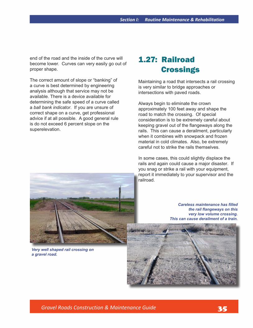
1.27: Railroad CrossingsMaintaining a road that intersects a rail crossing is very similar to bridge approaches or intersections with paved roads.
Always begin to eliminate the crown approximately 100 feet away and shape the road to match the crossing. Of special consideration is to be extremely careful about keeping gravel out of the flangeways along the rails. This can cause a derailment, particularly when it combines with snowpack and frozen material in cold climates. Also, be extremely careful not to strike the rails themselves.
In some cases, this could slightly displace the rails and again could cause a major disaster. If you snag or strike a rail with your equipment, report it immediately to your supervisor and the railroad.
Very well shaped rail crossing on a gravel road.
Careless maintenance has filledthe rail flangeways on thisvery low volume crossing.
This can cause derailment of a train.

Gravel Roads Construction & Maintenance Guide 36
1.28: DrivewaysThe public road should always retain its normal crowned shape while passing driveways. Too often the gravel builds up on the road at a driveway entrance as shown in Figure 11. This changes the shape of the roadway itself, which can cause loss of control of vehicles. This condition needs to be reshaped.
The driveway entrance should always match the edge of the public road as shown in Figure 12. To reduce maintenance problems, implement a permitting process. It should address the proper control of grade to match road edge, adequate width, and drainage.
FIGURE 11 – Improper matching of driveway and public road.
FIGURE 12 – Proper matching of driveway and public road.
Section I: Routine Maintenance & Rehabilitation

Gravel Roads Construction & Maintenance Guide 37
Section I: Routine Maintenance & Rehabilitation
1.29: Cattle GuardsA simple structure called a cattle guard is common in parts of the high plains and mountain west in the United States. These structures are commonly found on low volume roads in national forests and on public or private lands where cattle or other livestock are allowed to graze on open range. The cattle guard allows traffic to pass from oneparcel of land to another without opening and closing gates. The cattle guard is a series of heavy iron bars or pipes placed across the roadway that generally appears like a heavy grate. A cavity below the bars or pipes is generally 12- to 18-inches deep. These structures confine cattle and other livestocksince, by instinct, they will not cross them for fear of falling through the grate.
Care must be taken not to spill gravel into the cattle guard. Poor quality gravel with too much loose aggregate aggravates the problem of material spilling into the cavity spill gravel into the cattle guard.
Cattle guards are a special maintenance challenge when installed on gravel roads. The approach to them should be treated much like blading up to a bridge deck. Begin to eliminate normal crown approximately 100 feet from the guard. The road must then be shaped to match the cattle guard. However, gravel should not be spilled into the cavity below the grate. If this is done repeatedly, the hollow area below will be filled with gravel and cattle will simply walk out. Stop the grader 2- to 3-feet from the guard and backdragloose material away from the structure.Then, handwork will often have to be doneat the edge of the cattle guard to maintaina smooth crossing for traffic.
Road is shaped very well for a smooth crossing over the cattle guard.

Gravel Roads Construction & Maintenance Guide 38
1.30: Soft and Weak SubgradeAlthough it is extremely important that surface and subsurface water flows off of and away from roadways, there are situations where water simply cannot be kept away. A good example is a section of road that passes through swampland or wetlands which naturally occur and cannot be drained. These areas will very often have weak subgrades, which cannot support heavy loads. Sometimes it is even hard to maintain the road for light traffic. The road will rut and potholes will be formed very quickly due to very poor subgrade soil support.
This requires more than routine maintenance and reshaping if the problem is to be fixed permanently. Generally, there are only two solutions. One is to excavate and remove the weak, wet soil. Occasionally, the existing roadway is wide enough that new material can be brought in to raise the road and the top-width of the finished surface will still be adequate. In this case, undercutting will not be necessary. The new material brought in will vary depending on what is available in the region. One thing is critical: it must be clean and drainable. It is also advisable to get engineering advice to make sure the new material is suitable before starting rehabilitation.
The second method is similar, except a product called a geotextile or geosynthetic is
added. These products are often called “fabrics” and “grids” in the field. The procedure is virtually the same as described before, but a fabric and/or grid is placed over the subgrade soil before the select material is brought in. A woven or non-woven fabric (geotextile) placed on the subgrade becomes a separator between the weak soil and the new material placed above it. The accompanying photos show placing geotextiles in a separation function. This prevents very fine,wet silt and clay type soils from pumping or migrating up into the new material. The pumping action occurs when traffic passes over thesurface and the road deflects under the load.Pressure from the load will cause water in the subgrade to rise to the surface and carry fine soilparticles with it. This will contaminate and weaken the new material very quickly and make it weak, undrainable, and unstable. A fabric prevents this by filtering out the fine soils while allowing wateto pass through it and drain out of the clean, granular material above.
Example of road that carries heavy trucks and begins to fail in any wet condition or during
spring thaw in cold regions.
Section I: Routine Maintenance & Rehabilitation
Gravel Roads Construction & Maintenance Guide 39
Section I: Routine Maintenance & Rehabilitation
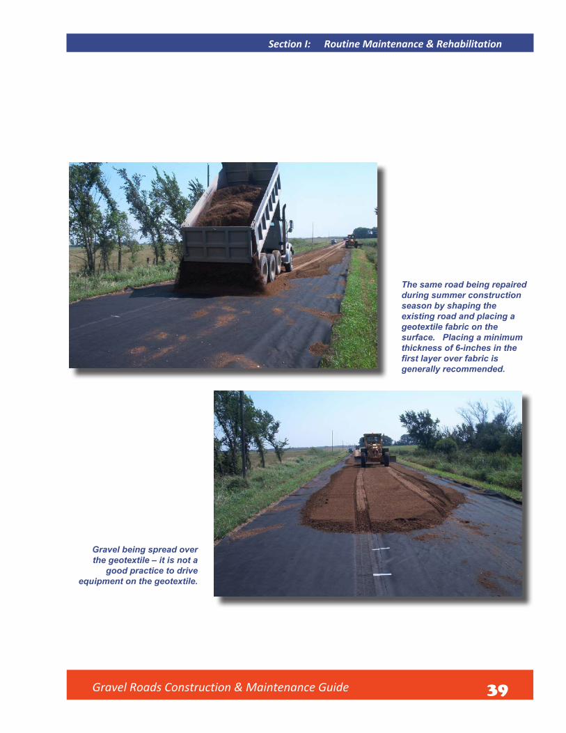
The same road being repaired during summer construction season by shaping the existing road and placing a geotextile fabric on the surface. Placing a minimum thickness of 6-inches in the first layer over fabric isgenerally recommended.
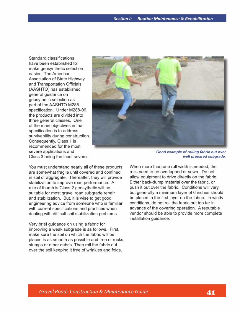
Gravel being spread over the geotextile – it is not a
good practice to drive equipment on the geotextile.

Gravel Roads Construction & Maintenance Guide 40
Finished project had 10 inches total compacted thick-ness of gravel placed over the geotextile.
Documentation of performance after
12 years.
The road foundation was never repaired again; only surface
maintenance has been done.
Section I: Routine Maintenance & Rehabilitation
Gravel Roads Construction & Maintenance Guide 41
Section I: Routine Maintenance & Rehabilitation
Standard classificationshave been established to make geosynthetic selection easier. The American Association of State Highway and Transportation Officials(AASHTO) has established general guidance on geosythetic selection as part of the AASHTO M288 specification. Under M288-06,the products are divided into three general classes. One of the main objectives in that specification is to addresssurvivability during construction. Consequently, Class 1 is recommended for the most severe applications andClass 3 being the least severe.
You must understand nearly all of these products are somewhat fragile until covered and confinedin soil or aggregate. Thereafter, they will provide stabilization to improve road performance. A rule of thumb is Class 2 geosythetic will be suitable for most gravel road subgrade repair and stabilization. But, it is wise to get good engineering advice from someone who is familiar with current specifications and practices whendealing with difficult soil stabilization problems.
Very brief guidance on using a fabric for improving a weak subgrade is as follows. First, make sure the soil on which the fabric will be placed is as smooth as possible and free of rocks, stumps or other debris. Then roll the fabric out over the soil keeping it free of wrinkles and folds.
Good example of rolling fabric out over well prepared subgrade.
When more than one roll width is needed, the rolls need to be overlapped or sewn. Do not allow equipment to drive directly on the fabric. Either back-dump material over the fabric, or push it out over the fabric. Conditions will vary, but generally a minimum layer of 6 inches should be placed in the first layer on the fabric. In windyconditions, do not roll the fabric out too far in advance of the covering operation. A reputable vendor should be able to provide more complete installation guidance.

Gravel Roads Construction & Maintenance Guide 42
Keep fabric as free of wrinkles and folds as possible. It must be pinned down or anchored quickly, especially in windy conditions, to hold it in place until it is covered.
Overlap not less than 18 inches is a good practice when more than one width of fabric is required.
Section I: Routine Maintenance & Rehabilitation

Gravel Roads Construction & Maintenance Guide 43
Section I: Routine Maintenance & Rehabilitation
Good practice of dumping and pushing material out over the fabric to avoid damage during construction.
A grid can also be used either in combination with or without fabrics. Grids are very strong geosynthetics which, in simplest terms, confinethe material placed on them and do not allow lateral movement or “shoving” of the material. Grids have been rolled out over swamps and roads built over them with remarkably good results. The ability to carry and distribute the roadway materials and traffic load is referred toas a “snowshoe” effect. Grids can also be placed within layers of select material. There are many types and variations of these products.
Once the subgrade has been strengthened, a good layer of surface gravel can be placed and the road can be maintained as any other gravel road. The initial cost of stabilizing a weak road section can be expensive, but it will result in low maintenance costs thereafter, and will often make these projects cost effective.

Gravel Roads Construction & Maintenance Guide 44

45
Section II: Drainage
2.1: Introduction
An often-repeated adage in the road construction and maintenance business is “The three most important things to understand in building and maintaining roads are drainage, drainage, and drainage!” This certainly does get an important message across. But, too often, this critical issue is ignored when building and maintaining local roads. When drainage is poor, the best efforts to rehabilitate or maintain roads will bring disappointing results. When water can be drained off of road surfaces and out of roadbed soils, the road will invariably become easier to maintain. Good drainage is critical even in arid regions.
Lack of ditch drainage affects the performance of this road.

Gravel Roads Construction & Maintenance Guide
Section II: Drainage
This can hardly be emphasized enough. However, this is not a drainage manual and therefore the discussion will only cover basic drainage matters. A good drainage reference is Roadway and Roadside Drainage by the Cornell Local Roads Program at Cornell University. Call the local technical assistance program (LTAP) center in your State to obtain a copy.
Too often the maintenance team deals with surface problems that are caused by wet and weak soil conditions below the road. Since gravel
roads generally carry low volumes of traffic anddo not have large budget allocations for drainage improvement projects, maintenance crews must do what it takes to restore or keep drainage working on gravel roads. Previous sections of this manual have already discussed the road profile which is the first line of defense fogood drainage. The discussion will now continue with brief information on three more basic drain-age topics: ditches, culverts and bridges, and underdrains.
This road has a poor cross section. Drainage is important, even though the road is located in a semi-arid region.
46

Gravel Roads Construction & Maintenance Guide 47
Section II: Drainage
Remarkable difference in these two roads that carry similar volumes of traffic.They are located in the same region of the country and the photos were taken on the same day. The major difference is drainage.
The first photo shows awell-drained road while the second photo shows a poorly drained road with no ditches resulting in a poor performance. Guid-ance on recommended shape of foreslope and ditch is provided in Appendix A.

Gravel Roads Construction & Maintenance Guide 48
Section II: Drainage
2.2: Ditches Drainage of water from the road surface to a ditch is imperative for maintaining the design life of the road. The most important and common drainage feature needed on a rural road is the roadside ditch. Every effort must be made to maintain at least a minimal ditch. If the ditch becomes obstructed from eroded soil or debris, it must be cleaned. Sometimes this can be a major project requiring loaders, excavators, trucks or other equipment. However, during a dry period, a maintenance operator with nothing more than a motor grader can do basic work to restore ditch drainage.
This road is located in mountainous terrain, yet the motor grader operator has been able to maintain a small ditch for roadside drainage and the road performs well.
A V-ditch does not work well in highly erodible soils
as shown here. A flat bottomditch should have been
constructed and erosion and sediment control should
have been done.

Gravel Roads Construction & Maintenance Guide 49
Section II: Drainage
Nicely reshaped flatbottom ditch built
with a motor grader. Seeding, erosion
and sediment control need
to follow this ditch reshaping operation.
Good work being done to restore ditch drainage from the shoulder line of a road in the Great Plains. This will allow good drainage.
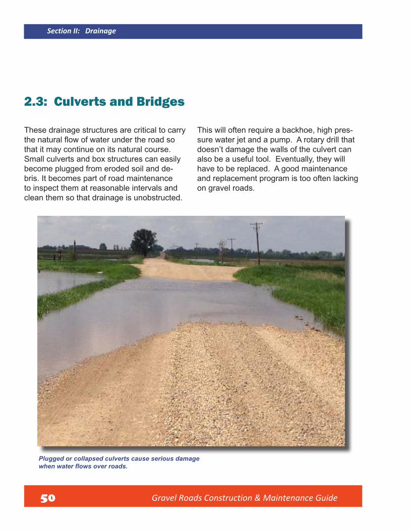
Gravel Roads Construction & Maintenance Guide 50
Section II: Drainage
2.3: Culverts and Bridges
These drainage structures are critical to carry the natural flow of water under the road sothat it may continue on its natural course. Small culverts and box structures can easily become plugged from eroded soil and de-bris. It becomes part of road maintenance to inspect them at reasonable intervals and clean them so that drainage is unobstructed.
This will often require a backhoe, high pres-sure water jet and a pump. A rotary drill that doesn’t damage the walls of the culvert can also be a useful tool. Eventually, they will have to be replaced. A good maintenance and replacement program is too often lacking on gravel roads.
Plugged or collapsed culverts cause serious damagewhen water flows over roads.

Gravel Roads Construction & Maintenance Guide 51
Section II: Drainage
Good work to clean a ditch and install new culvert under a gravel road. Note: Culvert is placed perfectly on the flow lineof the ditch. This eliminates any accumulation of water at the inlet or outlet of the culvert and provides excellent cross drainage.
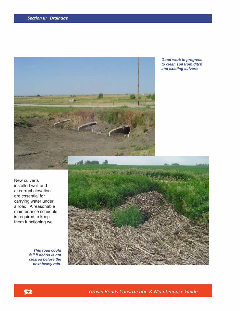
Gravel Roads Construction & Maintenance Guide 52
Section II: Drainage
Good work in progress to clean soil from ditch and existing culverts.
New culverts installed well and at correct elevation are essential for carrying water under a road. A reasonable maintenance schedule is required to keep them functioning well.
This road could fail if debris is not cleared before the
next heavy rain.

Gravel Roads Construction & Maintenance Guide 53
Section II: Drainage
Bridges or larger box structures generally handle significantly morewater flow than culverts.They should be inspected after any major rain event or after spring snow-melt in northern regions. To reduce the risk of the entire road being washed out, make sure the channel is clean and unobstructed.
Bridges and large structures can be
damaged after a major flood event.
A large double box structure, completely plugged with debris after flooding and the samestructure after debris removal and channel clean-up by a county maintenance crew.
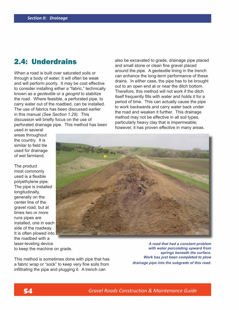
Gravel Roads Construction & Maintenance Guide 54
Section II: Drainage
2.4: Underdrains When a road is built over saturated soils or through a body of water, it will often be weak and will perform poorly. It may be cost effective to consider installing either a “fabric,” technically known as a geotextile or a geogrid to stabilize the road. Where feasible, a perforated pipe, to carry water out of the roadbed, can be installed. The use of fabrics has been discussed earlier in this manual (See Section 1.29). This discussion will briefly focus on the use ofperforated drainage pipe. This method has been used in several areas throughout the country. It is similar to field tileused for drainage of wet farmland.
The product most commonly used is a flexiblepolyethylene pipe. The pipe is installed longitudinally, generally on the center line of the gravel road, but at times two or more runs pipes are installed, one in each side of the roadway.It is often plowed into the roadbed with a laser-leveling device to keep the machine on grade.
This method is sometimes done with pipe that has a fabric wrap or “sock” to keep very fine soils frominfiltrating the pipe and plugging it. A trench can
also be excavated to grade, drainage pipe placed and small stone or clean fine gravel placedaround the pipe. A geotextile lining in the trench can enhance the long-term performance of these drains. In either case, the pipe has to be brought out to an open end at or near the ditch bottom. Therefore, this method will not work if the ditch itself frequently fills with water and holds it for aperiod of time. This can actually cause the pipe to work backwards and carry water back under the road and weaken it further. This drainage method may not be effective in all soil types, particularly heavy clay that is impermeable; however, it has proven effective in many areas.
A road that had a constant problem with water percolating upward from
springs beneath the surface. Work has just been completed to plow
drainage pipe into the subgrade of this road.

Gravel Roads Construction & Maintenance Guide 55
Section II: Drainage
This large tile plow was brought in which is commonly used in some regions to install polyethylene pipe into farm fields for drainagepurposes. This type of machine has also been used to plow drain tile into gravel roads with great success.
Common flexible polyethylenedrainage pipe is plowed below the
surface and brought out to the surface on the foreslope at regular
intervals to complete this work.

Gravel Roads Construction & Maintenance Guide
Section III: Surface Gravel

57
Section III: Surface Gravel
3.1: What is Good Gravel?
The answer to this question will vary depending on the region, local sources of aggregate available and other factors. Some regions of the country do not have good sources of gravel (technically called aggregate in many places). A few coastal regions in the United States use seashells for surface material on their unpaved roads; other regions use materials such as clinker (locally known as “scoria” in some States), slag, reclaimed materials such as recycled asphalt or concrete pavement, and others as applicable in different regions of the country. However, this section of the manual will discuss the most common sources of material. They are quarry aggregates such as limestone, quartzite and granite; glacial deposits of stone, sand, silt and clay; and river gravels that generally are a mix of stone and sand. One thing should be stressed: it pays to use the best quality material available.
High quality surface gravel with a good blend of stone, sand and fine-sized particles on a mountainroad.
Gravel Roads Construction & Maintenance Guide
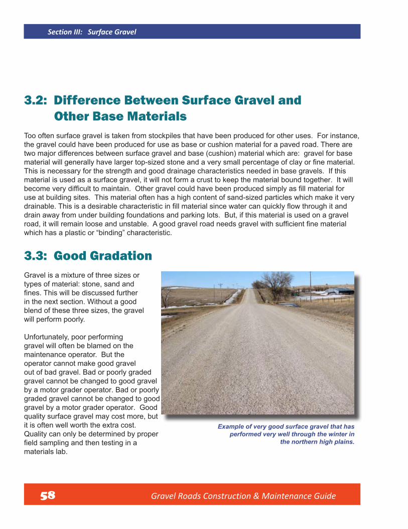
Gravel Roads Construction & Maintenance Guide 58
Section III: Surface Gravel
3.2: Difference Between Surface Gravel and Other Base Materials Too often surface gravel is taken from stockpiles that have been produced for other uses. For instance, the gravel could have been produced for use as base or cushion material for a paved road. There are two major differences between surface gravel and base (cushion) material which are: gravel for base material will generally have larger top-sized stone and a very small percentage of clay or fine material. This is necessary for the strength and good drainage characteristics needed in base gravels. If this material is used as a surface gravel, it will not form a crust to keep the material bound together. It will become very difficult to maintain. Other gravel could have been produced simply as fill material foruse at building sites. This material often has a high content of sand-sized particles which make it very drainable. This is a desirable characteristic in fill material since water can quickly flow through it and drain away from under building foundations and parking lots. But, if this material is used on a gravel road, it will remain loose and unstable. A good gravel road needs gravel with sufficient fine material which has a plastic or “binding” characteristic.
3.3: Good Gradation Gravel is a mixture of three sizes or types of material: stone, sand and fines. This will be discussed further in the next section. Without a good blend of these three sizes, the gravel will perform poorly.
Unfortunately, poor performing gravel will often be blamed on the maintenance operator. But the operator cannot make good gravel out of bad gravel. Bad or poorly graded gravel cannot be changed to good gravel by a motor grader operator. Bad or poorly graded gravel cannot be changed to good gravel by a motor grader operator. Good quality surface gravel may cost more, but it is often well worth the extra cost. Quality can only be determined by proper field sampling and then testing in a materials lab.
Example of very good surface gravel that has performed very well through the winter in
the northern high plains.
Gravel Roads Construction & Maintenance Guide 59
In many regions of the country, this is a natural clay which gives the gravel a strong cohesive characteristic and keeps a reasonably tight surface especially during periods of dry weather.
Some of the fine material in surface gravel will be lost under traffic action in the form of dust that rises from the surface and simply blows away. This can be compensated for by specifying a higher percentage of fines in the new gravel and also adding a dust palliative if feasible. (See Section IV for information on dust palliatives.) However, no gravel surface will perform like pavement! There will be some loose aggregate or “float” on the surface of virtually all gravel roads. But striving to get as good a material as budgets and available sources allow will improve the performance of a gravel road.
Good surface gravel has the appropriate percentage of stone, or coarse aggregate, which gives strength to support loads — particularly in wet weather conditions. It also needs an appropriate percentage of sand-sized particles, or fine aggregate, to fill the void between the stones to provide stability. The final requirement is an appropriate percentage of plastic, very fine particles to bind the material together which allows a gravel road to form a crust and shed water. The simplest definition of coarse and fine aggregate as defined by AASHTO is that material retained on (coarse), or passes through (fine) a No. 4 Sieve in the laboratory testing process. What is referred to as very fine material is that portion of the fine aggregate that passes a No. 200 sieve. These fine particles are extremely small, less than 0.075 mm in size, that cannot be seen individually by the human eye.
3.4: Benefit of CrushingIn some cases the gravel may simply be loaded onto trucks without processing. This is often referred to as “bank run” or “pit run” gravel. There are few natural deposits of material that have an ideal gradation without the need for further processing. In some areas of the country it is still common to process gravel simply by screening to a maximum top size. A great benefit is gained from processing the material bycrushing. This means that a portion of the stone will be fractured in the crushing process. The broken stones will embed into the surface of a gravel road much better than rounded, natural-shaped stone. It also means that the fractured stone resists movement under loads better and provides additional strength or stability. This will vary throughout the country, but bank run gravels are nearly always improved through the crushing process. Quarry gravels are often very good material since they are composed of virtually all fractured particles.
3.5 Recycled Asphalt As more of our asphalt pavements wear out, many of them are recycled. This is usually done by milling or crushing. Sometimes the material is available for use on a gravel road. It can be a good surface, but there are pitfalls. In this material, the bituminous portion of the old pavement becomes the binder.
Section III: Surface Gravel

Gravel Roads Construction & Maintenance Guide 60
Section III: Surface Gravel
When placed on a road in hot weather, the recycled asphalt can take on the characteristic of pavement. It can become so tightly bound blade maintenance cannot be done. But it will be a weak pavement due to the oxidized condition of most recycled asphalt. It will often develop potholes and will be hard to maintain. To help overcome this problem, the material should be placed at a minimum 3-inch compacted depth and only on a road that has a strong subgrade. A better option is to mix the recycled asphalt with new surface gravel. As little as 30 percent and as much as 60 percent of new surface gravel blended with recycled asphalt has performed well on local roads.
Example of mixed recycled asphalt and surface gravel used on a road with very low traffic.
This will generally provide a material that has a reasonably good binding characteristic, but remains workable for maintenance and reshaping. Recycled asphalt has also been mixed with crushed, recycled concrete and the performance has been acceptable.
3.6: The Benefit of Testing Aggregates What are the benefits of testing aggregate? It is very important to understand that all gravels are not the same. One can tell a little about them by visual inspection or by running your hands through the material but real quality can only be determined by testing. The primary concern here should be gradation and plasticity, or cohesive characteristic, of the fine portion of the material. Furthertesting can provide information on items such as hardness or soundness, gradation, percentage of fractured stone and plasticity index, all of which affect the performance of surface gravel.
Illustration of the mix of material separated through sieve testing on the road
from which the sample was taken.

Gravel Roads Construction & Maintenance Guide 61
Course Sieves
Intermediate Sieves
Fine Sieves
Pan
FIGURE 13: Testing gradation.
Illustration of stack of sieves used in testing aggregate gradation.
Section III: Surface Gravel

Gravel Roads Construction & Maintenance Guide 62
Section III: Surface Gravel
3.7: Reasons for Testing All managers and decision makers in local government need a good understanding of the benefit oftesting aggregates in order to work towards better quality in road and street maintenance. Not everyone needs to understand how to do the testing. Testing requires special knowledge and equipment which is generally not available or affordable to most local governments. You simply need to recognize that knowing more about the quality of aggregate that is used in construction and maintenance operations will contribute to better road construction and maintenance. This knowledge gives power to decision makers to specify good materials, to know when to accept or reject materials, and to communicate better with crushing contractors, consultants, commercial suppliers and others involved in the business of constructing and maintaining roads. Often an objection is raised to sampling and testing because the cost is too high. This claim can be countered with the argument that if a few, or many thousand tons of aggregate are going to be purchased, is it not wise to invest a comparatively small amount of money in the testing of the material to insure that good quality aggregate is being purchased? It is a good practice to test the aggregate before placing it on the road. Also, if the tests fail, you can work with the supplier to try to improve or reject the material.
3.8: Sampling Another issue critical to testing aggregate is obtaining a good sample of the material to be tested. Knowing how to get a good representative sample from a crushing operation, a stockpile, a windrow, or from the existing surface is absolutely critical in getting valid test results from a lab. Poor sampling techniques have led to more controversy in aggregate testing than any other factor. Some common problems are obtaining a sample from only one location in a stockpile or windrow, getting a sample from the discharge conveyor belt that is not representative of the entire stream of material going up the belt, not gathering enough quantity for testing and not getting the sample to the lab in a timely manner. Every effort must be made to make sure that the sample brought to a lab is truly representative of the material in the field. It is wise to follow national standards such as the ASTM or the AASHTO standard for aggregate sampling. It is always advisable to work with an experienced sampler if you are not familiar with sampling.
3.9: Sieve Analysis Depending on what the material is to be used for, the ideal blend of stone, sand and fine materialvaries. For example, good surface material for a gravel road would need more material passing a #200 sieve (true fines) than a good base material. There is also a difference in the need for a plastic or binding characteristic in the fine material. Surface gravel needs some natural clay which gives a“binding characteristic.” The adjacent chart is an example of one State’s base and gravel surfacing specifications.

Gravel Roads Construction & Maintenance Guide 63
If your State has a surface gravel or aggregate specification it is highly recommended that specification be used. Local governments are not held to these specifications when doing their own construction and maintenance work without State or Federal funding and oversight. Yet, it is wise to be familiar with them and follow them whenever possible. If you choose to modify the specifications to suit a local material source or project, it is best to begin with a State specification. The characteristics of the material and uniform quality will have a major impact on the performance of the roadway surface.
Notice the major differences in the specification in the top-sized material and the smallest sized material. The base course requires 100 percent of the material to pass a 1-inch sieve, but allows up to 20 percent of the stone to be retained on the 3/4 inch sieve. While this could make excellent base gravel, it will likely perform poorly if used as gravel surfacing. There would be too much large stone resulting in very difficult blade maintenance. Also, the high percentage of coarse material would make a rough driving surface. A higher percentage of large stone is needed for strength in the base course, but will be detrimental to surface gravel. Good surface gravel that goes into a tightly bound state will provide a good driving surface.
Table 1. Example of Gradation Requirements and Plasticity for Two Types of Materials
Requirement Sieve
Aggregate Base Course Percent Passing
Gravel Surfacing Percent Passing
1” 100
3/4” 80-100 100
1/2” 68-91
No. 4 46-70 50-78
No. 8 34-54 37-67
No. 40 13-35 13-35
No. 200 3-12 *4-15
Plasticity Index 0-6 4-12
From: South Dakota Standard Specifications *Sometimes modified to 8-15 for better performance for Roads and Bridges
Section III: Surface Gravel
Gravel Roads Construction & Maintenance Guide 64
Section III: Surface Gravel
3.10: Fines and Plasticity IndexNotice also the difference in the fine material andthe plasticity index (PI) sometimes referred to as Atterberg Limits. While gravel surfacing allows as little as 4 percent and up to 15 percent (and sometimes modified to 8 to 15 percent) of thematerial to pass a #200 sieve, base course can have as little as 3 percent, but not more than 12 percent passing the same sieve. More importantly, the PI can be no less than 4 or as high as 12 in. surface gravel. The same index can fall to 0 in base course and rise to no more than 6. There is good reason for this. Good surface gravel needs a percentage of plastic material, usually natural clays, which will give the gravel a “binding” characteristic and hence a smooth driving surface. This is critical during dry weather.
During wet weather, the surface may rut a bit, but will quickly dry and harden in sunny and windy weather. The same material used as base would lose its strength and stability if it became wet and cause rutting or even failure of the pavement. Too often the same gravel is used for both base work
and surface gravel. Generally, it will be good for one purpose or the other, but will not work for both applications.
Appendix B contains a sample of a complete Screen Analysis and PI Worksheet typical of those used by testers across the country. Once again, it should be stressed that only by sampling and testing the aggregate can one really determine the quality of the material. Simple visual inspection can be misleading. One thing in particular that is very hard to determine without testing is plasticity. This is a laboratory test which, in simplified terms, tells you whether the fines are primarily clays or silts. If you are not familiar with this testing, the whole process may seem very confusing. Yet, it really pays to increase your knowledge of these matters in order to be a better manager. Every local road or street department manager has a big job and there is never enough money to cover all of the needs. It is imperative that money be spent wisely.
3.11: Reduced Blading and Maintenance Costs By spending some money to test material for quality, overall maintenance costs will be reduced. Good gravel that has good gradation and plasticity will compact well. It will develop a tightly bound surface that needs less maintenance. Problems with excess washboarding, rutting in wet weather, or loosening (floating) in dry weather, will be greatly reduced.
It is well worth the effort to better understand the benefits of aggregate testing to assure good quality surface gravel. A case study coordinated by South Dakota local technical assistance program entitled Gravel Surfacing Guidelines that even though higher quality gravel will cost more to purchase, it will prove to be cheaper to maintain over a life cycle. Part of the study was done on a 1-mile test section in eastern South Dakota with three types of surface gravel placed on the section. The three types were 1) Substandard material with only top-size control of stone at 100 percent passing the one-inch sieve,2) Material that met the South Dakota DOT’s Gravel Surfacing specification but had near minimum

Gravel Roads Construction & Maintenance Guide 65
required fines and PI, and 3) A modified material that had the maximum allowable of fine materialand PI of 7. The test section was located in an agricultural community where corn and soybeans are primary crops. Average annual daily traffic volume was 100 vehicles per day with estimated 12 percent heavy trucks. After 3 years of observation, the substandard material became virtually impossible to maintain due to excess loose aggregate and significant corrugation (washboarding). New gravel had to be hauled and placed on that portion of the test section. The standard material performed better and was still in acceptable condition after 3 years. The modified material exceeded expectations. It required up to 75 percent less blade maintenance, never developed any corrugation and remained in a good, bound state even in periods of dry weather. See Chart 1: Surface Gravel (below) for a comparison of loose aggregate by material type on the surface of the test section. This was measured 1 year after construction. This is a critical comparison since loose aggregate is a major cause of corrugation (washboard) and triggers the need for blade maintenance. The difference was remarkable in that the substandard material on the section had the equivalent of 405 tons of loose aggregate on 1-mile compared to only 211 and 71 tons respectively where standard and modified materials were used.
CHART 1: Surface Gravel Quality Comparison. Difference in Volume of Loose Aggregate Measured in South Dakota Surface Gravel Quality Comparison Test
South Dakota Gravel Quality Comparison Test Tons of loose aggregate on 1 mile
Substandard Surface Gravel Meets Standard Specifications Modified Specification
450
400
350
300
250
200
150
100
50
0
Section III: Surface Gravel

Gravel Roads Construction & Maintenance Guide 66
Section III: Surface Gravel
3.12: Process for Obtaining Good Gravel An agency must strive to locate and use good gravel even if it costs a little extra. The long term benefitsin terms of less maintenance will often pay for the extra cost. The initial cost should not be the primary consideration when purchasing gravel.
The first road actuallycarries more traffic butperforms much better due to high quality gravel. The gravel on the second road is substandard with very large top-sized stone and poor overall gradation.
These roads show a remarkable contrast in surface condition due
to quality of surface gravel.

Gravel Roads Construction & Maintenance Guide 67
3.13: Establish SpecificationsGravel for local roads is often bought from a local supplier at a negotiated or bid price for an estimated quantity. There may be some assurance that the gravel will perform well on the road based on past experience. However, material sources can change rapidly as the material is removed. The only real assurance of getting good quality material is to establish a specification and then sample and test the product to make sure these specifications are met. If one is confident in knowledge of surface grave and wishes to change the specifications, that is fine; but it is wise to use the State specification a benchmark from which to work. For example, State specifications may show a “Class I Surface Aggregate” designation for surface gravel. You may want a higher minimum requirement for plasticity or perhaps a smaller top size on the rock. State clearly in your specification that you want a “Modified Class I Surface Aggregate” and then clearly indicate what your modifications are. If you have not done so, familiarize yourself with your State specifications.
3.14: Communicate with Suppliers Many problems are quickly solved when people make an effort to explain clearly what their problems or needs are. In regard to the specifications just discussed, many commercial aggregate suppliers can provide test data from their stockpiles to show the gradation of their material. They may have further data such as plasticity index, percentage of fractured faces, soundness, etc. You simply have to ask for it. It is wise to take a sample and test independently to verify their data. Good suppliers welcome this.
3.15: Handling GravelIt is not common for maintenance operators or field supervisors to beinvolved in the actual production process of the gravel that is used on their roads. Yet it is very helpful to understand how the material should be handled from the time it is taken from the quarry face or the gravel bank in a pit. There are certain problems that can arise from the time the material is first removed from theearth until it is finally placed on the road. It may be wise to visit the site where your gravel is being produced to see if it is being handled well. Example of poor management of a gravel pit.
Note top soil was not removed from the top of the working face of the gravel bank and has fallen down into the working area.
This will contaminate the gravel with organic material and could spread noxious weeds.
Section III: Surface Gravel
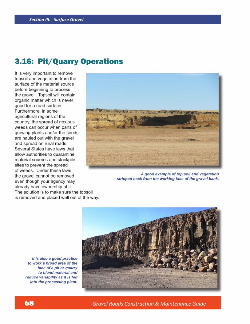
Gravel Roads Construction & Maintenance Guide 68
Section III: Surface Gravel
3.16: Pit/Quarry Operations It is very important to remove topsoil and vegetation from the surface of the material source before beginning to process the gravel. Topsoil will contain organic matter which is never good for a road surface. Furthermore, in some agricultural regions of the country, the spread of noxious weeds can occur when parts of growing plants and/or the seeds are hauled out with the gravel and spread on rural roads. Several States have laws that allow authorities to quarantine material sources and stockpile sites to prevent the spread of weeds. Under these laws, the gravel cannot be removed even though your agency may already have ownership of it. The solution is to make sure the topsoil is removed and placed well out of the way.
A good example of top soil and vegetation stripped back from the working face of the gravel bank.
It is also a good practice to work a broad area of the
face of a pit or quarry to blend material and
reduce variability as it is fed into the processing plant.

Gravel Roads Construction & Maintenance Guide 69
A bad example of taking material from a narrow area of the
working face of a gravel bank not allowing good
blending of material.
The next area of concern is how the material is being removed from the working face of the quarry or pit. Almost any material source will have variations in the layers of gravel. Good crushing contractors will remove the material by working a broad area of the face. This is essential to have material that is blended well as it goes into the crusher. Even a pit or quarry that appears to have very uniform layers of material will still have variations such as clay or silt seams which can suddenly change in thickness or disappear. This
can really affect the quality of the gravel. Good loader or dozer operators are key players in getting a good blend of gravel right at the start of processing.
Another problem commonly encountered is in the processing plant itself. These plants can be different types or combinations such as jaw, cone
Below, the discharge conveyor from a crushing plant is in the foreground. Notice how badly segregated the material is as it is carried up to the stockpile on a belt stacker. This invariably leads to problems illustrated in the two photos to the right.
Notice the dramatic difference in the two sides of the stockpile. The inside of the pile (seen here) has an excess of fine material..
...while the back side (seen here) has excess stone. This could have been prevented
by eliminating segregation on the stacker belt.
Section III: Surface Gravel
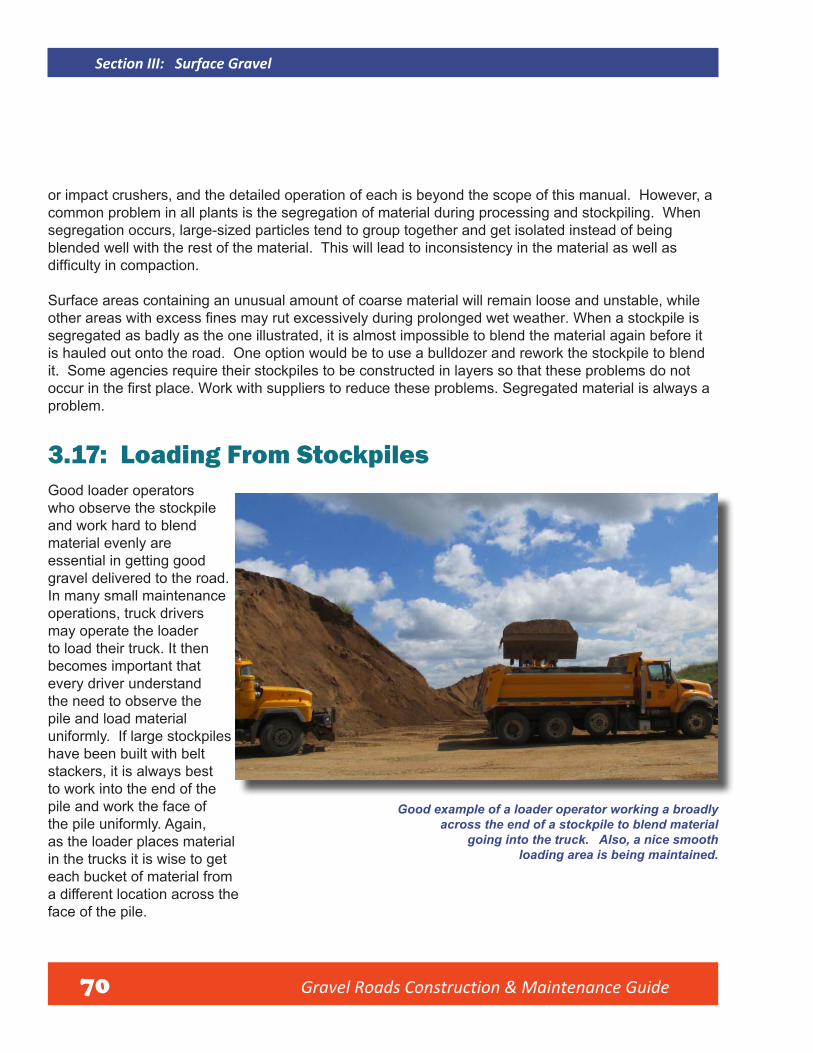
Gravel Roads Construction & Maintenance Guide 70
Section III: Surface Gravel
or impact crushers, and the detailed operation of each is beyond the scope of this manual. However, a common problem in all plants is the segregation of material during processing and stockpiling. When segregation occurs, large-sized particles tend to group together and get isolated instead of being blended well with the rest of the material. This will lead to inconsistency in the material as well as difficulty in compaction.
Surface areas containing an unusual amount of coarse material will remain loose and unstable, while other areas with excess fines may rut excessively during prolonged wet weather. When a stockpile is segregated as badly as the one illustrated, it is almost impossible to blend the material again before it is hauled out onto the road. One option would be to use a bulldozer and rework the stockpile to blend it. Some agencies require their stockpiles to be constructed in layers so that these problems do not occur in the first place. Work with suppliers to reduce these problems. Segregated material is always a problem.
3.17: Loading From Stockpiles Good loader operators who observe the stockpile and work hard to blend material evenly are essential in getting good gravel delivered to the road. In many small maintenance operations, truck drivers may operate the loader to load their truck. It then becomes important that every driver understand the need to observe the pile and load material uniformly. If large stockpiles have been built with belt stackers, it is always best to work into the end of the pile and work the face of the pile uniformly. Again, as the loader places material in the trucks it is wise to get each bucket of material from a different location across the face of the pile.
Good example of a loader operator working a broadly across the end of a stockpile to blend material
going into the truck. Also, a nice smooth loading area is being maintained.
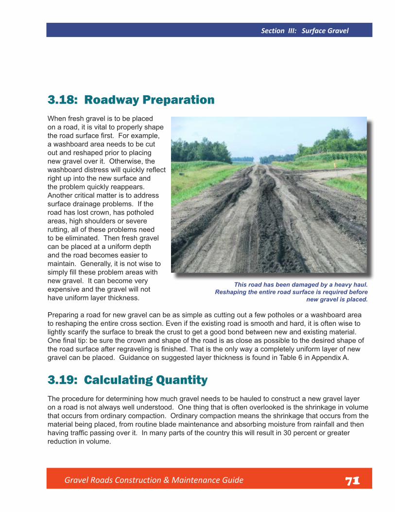
Gravel Roads Construction & Maintenance Guide
Section III: Surface Gravel
3.18: Roadway Preparation When fresh gravel is to be placed on a road, it is vital to properly shape the road surface first. For example,a washboard area needs to be cut out and reshaped prior to placing new gravel over it. Otherwise, the washboard distress will quickly reflectright up into the new surface and the problem quickly reappears. Another critical matter is to address surface drainage problems. If the road has lost crown, has potholed areas, high shoulders or severe rutting, all of these problems need to be eliminated. Then fresh gravel can be placed at a uniform depth and the road becomes easier to maintain. Generally, it is not wise to simply fill these problem areas withnew gravel. It can become very expensive and the gravel will not have uniform layer thickness.
Preparing a road for new gravel can be as simple as cutting out a few potholes or a washboard area to reshaping the entire cross section. Even if the existing road is smooth and hard, it is often wise to lightly scarify the surface to break the crust to get a good bond between new and existing material. One final tip: be sure the crown and shape of the road is as close as possible to the desired shape ofthe road surface after regraveling is finished. That is the only way a completely uniform layer of new gravel can be placed. Guidance on suggested layer thickness is found in Table 6 in Appendix A.
This road has been damaged by a heavy haul. Reshaping the entire road surface is required before
new gravel is placed.
3.19: Calculating QuantityThe procedure for determining how much gravel needs to be hauled to construct a new gravel layer on a road is not always well understood. One thing that is often overlooked is the shrinkage in volume that occurs from ordinary compaction. Ordinary compaction means the shrinkage that occurs from the material being placed, from routine blade maintenance and absorbing moisture from rainfall and then having traffic passing over it. In many parts of the country this will result in 30 percent or greaterreduction in volume.
71

Gravel Roads Construction & Maintenance Guide 72
Section III: Surface Gravel
A very good practice of measuring and marking spread distance for incoming trucks with a measuring wheel and shovel to make a mark on the surface.
Too often the volume of material is calculated in a loose state as it exists in the stockpile or as itis dumped from the truck. Material in the stockpile or in trucks is very loose and has very low density.
Remember to allow for shrinkage when calculating how much gravel depth is needed after the job is compacted and finished. Calculation then should be made for the distance that each truck can spreadits load. This is not always done in maintenance operations, but it is recommended. It’s the only way to really know for sure how much material is being placed. Appendix C of this manual has two charts to help in calculating quantities and the distance each truck can spread the load.
3.20: Hauling and Dumping Once hauling begins, it is wise to have a motor grader present to process and place the gravel immediately. The skill of the truck drivers can really make a regraveling operation work smoothly. When drivers are able to dump the load evenly and within the correct length that was marked, the grader operator’s job becomes much easier.
A good example of evenly dumping gravel on the road. Notice a grader is
ready at the hilltop to begin processing the gravel.

Gravel Roads Construction & Maintenance Guide 73
3.21: Windrowing, Equalizing and Spreading Once the gravel is dropped on the road, the grader operator should pick up the material and place it in a windrow. This will usually take more than one pass. It is called equalizing. This accomplishes two important things when handling gravel. It gives a final blending and mixing of thegravel, and it makes a windrow of very uniform volume. Once equalized, the material should be spread by the grader evenly on the roadway. A general rule is the minimum thickness when placing each layer of gravel is twice the thickness of the top-sized stone. Hence, if top-size stone in the gravel is 1-inch, the layer thickness should
be a minimum of 2-inches. Care must be taken not to carelessly cast material off the edge of the roadway where it cannot be recovered. When the material is finally placed across the roadway, it leaves a uniform depth of well-blended material that becomes the new gravel surface for the public to drive on. It all works better when everyone understands their job. While it is not possible everywhere, adding water and using rollers for compaction makes a better gravel road. It is recommended whenever possible.
The motor grader operator
beginning to process gravel
immediately after it is dumped
on the road.
Section III: Surface Gravel

Gravel Roads Construction & Maintenance Guide 74
Section III: Surface Gravel
This operator had done an excellent job of completely windrowing and equalizing the new gravel . . . .
and then spreads it evenly across the
road surface in a uniform layer.

75
Section IV:
Dust Control and Stabilization 4.1: Introduction To a greater or lesser extent, all gravel roads will give off dust under traffic. After all, they are unpaved roads that typically serve very low volumes of traffic, and some dust will be generated from that traffic. The amount of dust that a gravel road produces varies greatly depending primarily on the type of gravel, volume and type of traffic and annual precipitation. In areas of the country that receive a high amount of moisture, the problem is greatly reduced. Arid or semi-arid regions such as the desert southwest and much of the Great Plains region in the United States are prone to long periods of dry weather. Many regions around the world can have similar weather patterns. Dust can bring complaints in these areas especially if there are residences located directly adjacent to or near the road.
The quality and type of gravel has a great effect on the amount of dust. For example, some limestone gravels will produce significant dust in adry condition. But, some natural deposits of gravel that have some clay in the mix of material can take on a strong binding characteristic that will produce much less dust. Still, in prolonged dry weather, dust will be produced by virtually any paved surface! Whether to provide some type of dust control or not can be a hard decision to make. If traffic is high enough, road dust can impact the health of people and animals. There will be pressure to control the dust. On the other hand, the cost can be prohibitive and hard to justify if traffic volume is very low. The cost-benefit of doing this needs to be carefully considered. Most methods of dust control require annual treatment and it must be factored into annual maintenance costs.
Gravel Roads Construction & Maintenance Guide
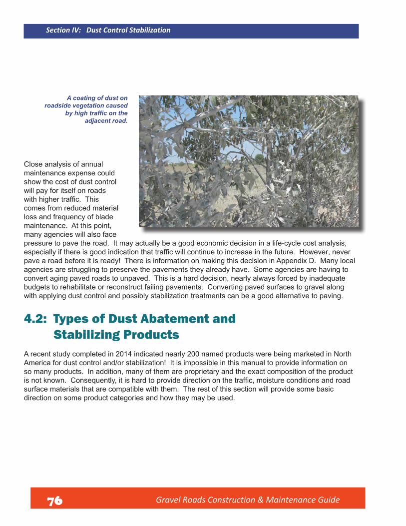
Section IV: Dust Control Stabilization
A coating of dust on roadside vegetation caused
by high traffic on theadjacent road.
Close analysis of annual maintenance expense could show the cost of dust control will pay for itself on roads with higher traffic. This comes from reduced material loss and frequency of blade maintenance. At this point, many agencies will also face pressure to pave the road. It may actually be a good economic decision in a life-cycle cost analysis, especially if there is good indication that traffic will continue to increase in the future. However, never pave a road before it is ready! There is information on making this decision in Appendix D. Many local agencies are struggling to preserve the pavements they already have. Some agencies are having to convert aging paved roads to unpaved. This is a hard decision, nearly always forced by inadequate budgets to rehabilitate or reconstruct failing pavements. Converting paved surfaces to gravel along with applying dust control and possibly stabilization treatments can be a good alternative to paving.
4.2: Types of Dust Abatement and Stabilizing Products A recent study completed in 2014 indicated nearly 200 named products were being marketed in North America for dust control and/or stabilization! It is impossible in this manual to provide information on so many products. In addition, many of them are proprietary and the exact composition of the product is not known. Consequently, it is hard to provide direction on the traffic, moisture conditions and roadsurface materials that are compatible with them. The rest of this section will provide some basic direction on some product categories and how they may be used.
Gravel Roads Cons truction & Maintenance Guide 76

Gravel Roads Construction & Maintenance Guide 77
Section IV: Dust Control Stabilization
4.2.1: Chlorides These are the most commonly used products across the country. They fall into three categories: Calcium Chloride in dry or liquid form, Magnesium Chloride generally in liquid form, and Sodium Chloride (road salt). Sodium is seldom used and is the least effective. Calcium and Magnesium Chloride can be very effective if used properly. They are hygroscopic products which, in simplest terms, means they draw moisture from the air and keep the road surface constantly damp. They are reasonably simple to use and relatively easy to apply. They can be applied to the surface as dust control treatment or can be mixed into a portion of the gravel layer to help provide stability. Either way, dust control is provided.
4.2.2: Resins These are products available under various commercial names. The basic composition of most is lignin sulfonate which is a by-product of the pulp milling industry. The product is sometimes called “tree sap” in the field. These products can be applied as a surface treatment for dust control, but work better when incorporated into the surface gravel. If incorporated, they provide some cohesion to bind the particles together and will provide some increased stability in the layer. Dust control is generally quite good either is as surface treatment or mixed into a portion of the gravel layer for stabilization.
4.2.3: Natural Clays Some regions of the country have excellent deposits of natural clay that are highly plastic and provide strong cohesion when added to gravel. Clay must to be mixed into a portion of the gravel layer. While providing cohesion and added stability to loose gravel, in prolonged dry weather the roads will seldom be completely dust free. It can also be difficult to haul the clay onto the road and mix it into the gravel. Because it is highly plastic, it tends to stick to truck boxes and requires a careful mixing process on the road surface to blend the clay and gravel. A special, extremely plastic clay called bentonite will provide a very tightly bound surface that significantly reduces dust. The amount of it to be added to gravel must be very carefully calculated and it must be mixed thoroughly. All clays can add stability to gravel that would otherwise be loose, dusty and hard to maintain. But, be careful! Too much clay will make the road unstable in a prolonged wet period and the road may rut and become unstable slick.

Section IV: Dust Control Stabilization
4.2.4: Petroleum Oils The use of cut-back liquid asphalts for surface treatment of gravel roads was once popular for dust control. However, because of a significant amount of fuel oil, kerosene or other distillates in these products, they have been banned in many places. It is wise to check with local DEP, EPA or other regulatory agencies for approval before using these products. Some emulsified asphalts (liquid asphalt blended with water using an emulsifying agent may work for this purpose, but they may not bond well when applied only as a surface treatment. The product must be applied with special asphalt application equipment. While emulsified asphalts may not always be effective as surface treatments for dust control, they can work well when mixed into a portion of the gravel layer for effective, long-term stabilization. A light application of the emulsified asphalt on the surface after stabilization will provide good dust control.
4.2.5: Portland Cement It is sometimes referred to as “soil cement” when used for stabilization. Portland cement must be mixed into a portion of the gravel or soil layer. It requires careful analysis and design to determine the amount of cement to be used and at what depth it must be applied to obtain desired stability and strength. While this is an expensive treatment in comparison to most others, it has the advantage of providing long-term performance spanning many years without any retreatment or rehabilitation. The primary benefit will be stabilization. Dust will be reduced, but not eliminated with cement.
4.2.6: Organic Nonpetroleum Oil This product category is marketed using many trade names and may not be available in all parts of the country. By generic definition, most of these are vegetable oils. Most of them are biodegradable products that have many of the characteristics of a light petroleum-based oil. It will seal a gravel surface providing a light coating over the surface that effectively reduces dust when it is used properly. These products need to be applied to a road with good structural strength to carry loads with little deflection of the surface. If excellent roadway strength is present, the product will keep the surface sealed and eliminate dust. Some of these can be mixed into the layer for stabilization as well.
4.2.7: Other Commercial Dust Control Agents or Stabilizers There are far too many of these to discuss individually. They are marketed under many trade names across the country. The burden to provide guidance on what type of surface gravel is compatible, how to prepare the surface and apply the product is on the supplier. If there is no reasonably assurance of performance, it is always wise to try a test section of no more than 1000 feet in length to see how any of these products work with your gravel or soil. One caution: Do not use waste products such as crankcase drain oil from engines. This is harmful to the environment and is in violation of the U.S. Environmental Protection Agency rules.
78 Gravel Roads Cons truction & Maintenance Guide

Gravel Roads Construction & Maintenance Guide
Section IV: Dust Control Stabilization
4.3: Benefits of Dust Control and Stabilization Providing dust control will make local residents happy which brings favor to a public agency. Reducing damage to the growth of vegetation and crops near the roadside is another benefit. Providing dust abatement in severe conditions can reduce health problems for people and animals. It can be hard to quantify the economic value of these benefits. However, in some regions, agencies must do dust control to reduce the particulate matter in the atmosphere or face a penalty from those tasked with enforcing environmental rules. As mentioned earlier, the impact on overall road maintenance cost can be positive as defined in the following paragraphs.
4.4: Reduced Dust It may be hard to justify the direct cost of any of these products for dust control alone. However, when the products are working well, the added benefit of a stabilized surface that controls the loss of fines through dusting is a great economic benefit. When the fines are lost from a gravel surface, the stone and sand-sized particles that remain will tend to remain loose on the surface, leading to some distresses like washboarding and reduced skid resistance. It will become very hard to maintain. Another benefit to simply reducing dust is improved road safety if frequent, severe dust conditions obscure visibility for drivers.
4.5: Reduced Gravel Loss This is an economic bonus to dust control when it is working well. As mentioned earlier, when dust control products are working well, the fine material in the gravel cannot loosen and dust away. This also means that the coarse aggregate in the gravel will tend to remain embedded in the surface and will not be lost to the edge of the road or even whipped off onto the foreslope from heavy traffic. Studies have shown that as much as one ton of aggregate per mile is lost each year for each vehicle that passes over a road daily. This means that a road carrying 200 vehicles per day will have a loss of 200 tons of aggregate per mile each year. Obviously this will vary with the amount of rainfall received, the quality of the gravel and other factors. But, retaining aggregate is an added benefit to dust control.
4.6: Reduced Blade Maintenance A road surface that remains tightly bound and stable will require much less blade maintenance. The manufacturers of some dust control products highly recommend that the surface should not be bladed at all after their products are applied. While extra blading, shaping and mixing is needed to prepare a road for dust control, the overall need for blade maintenance should be greatly reduced. This can be a great savings in equipment expense and labor. A county highway official once commented: “I don’t react to dust complaints. All gravel roads have dust. But I do react to high maintenance costs. When we have to regravel a road frequently and perform blade maintenance frequently, then it’s time to look at stabilizing the surface. Reduced maintenance is what we’re after. Dust control is just a bonus!”
79
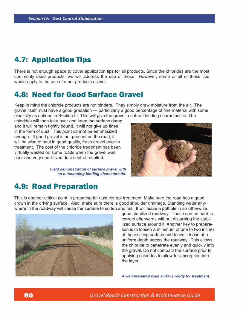
Gravel Roads Construction & Maintenance Guide
Section IV: Dust Control Stabilization
4.7: Application Tips There is not enough space to cover application tips for all products. Since the chlorides are the most commonly used products, we will address the use of those. However, some or all of these tips would apply to the use of other products as well.
4.8: Need for Good Surface Gravel Keep in mind the chloride products are not binders. They simply draw moisture from the air. The gravel itself must have a good gradation — particularly a good percentage of fine material with some plasticity as defined in Section III. This will give the gravel a natural binding characteristic. The chlorides will then take over and keep the surface damp and it will remain tightly bound. It will not give up fines in the form of dust. This point cannot be emphasized enough. If good gravel is not present on the road, it will be wise to haul in good quality, fresh gravel prior to treatment. The cost of the chloride treatment has been virtually wasted on some roads when the gravel was poor and very short-lived dust control resulted.
Field demonstration of surface gravel with an outstanding binding characteristic.
4.9: Road Preparation This is another critical point in preparing for dust control treatment. Make sure the road has a good crown in the driving surface. Also, make sure there is good shoulder drainage. Standing water any-where in the roadway will cause the surface to soften and fail. It will leave a pothole in an otherwise
good stabilized roadway. These can be hard to correct afterwards without disturbing the stabi-lized surface around it. Another key to prepara-tion is to loosen a minimum of one to two inches of the existing surface and leave it loose at a uniform depth across the roadway. This allows the chloride to penetrate evenly and quickly into the gravel. Do not compact the surface prior to applying chlorides to allow for absorption into the layer.
A well-prepared road surface ready for treatment.
80

Gravel Roads Construction & Maintenance Guide
Section IV: Dust Control Stabilization
An excellent tool for preparing loosening and preparing a road surface is a moldboard cutting edge equipped with carbide bits.
4.10: Optimum Moisture Once the road is prepared, make sure the gravel is in a moist state. It is important to have the gravel close to optimum moisture just before applying chlorides. This will cause the product to be absorbed much more quickly and evenly into the gravel. Never apply chloride to dry gravel. It will not absorb into a dry surface and will resist penetration into the surface. Premature failure is often the result.
If the gravel is dry, a good water truck is essential to apply water
evenly to moisten the material prior to treatment.
81

Section IV: Dust Control Stabilization
82
4.11: Applying the Product The most important need here is for equipment that can be calibrated accurately and that will apply either the liquid, pellets or flakes evenly across the surface. Then a good application rate needs to be selected. This will vary with the type of gravel being treated and the length of time dust control is needed. Check with vendors and experts in your area to see what recommended rates are. Next, watch the weather! If rain is forecast or appears to be likely, don’t take a chance. Rain on a freshly treated surface will leach out and dilute the chloride and cause it to run off the road. It can temporarily harm grass on adjacent areas. But the bigger problem will be poor performance afterwards.
Good example of application through a pressurized spray bar.
Note gravel is in a moist state ahead of the application to allow
absorption of the chloride.
Gravel Roads Construction & Maintenance Guide
Good example of even application.

Gravel Roads Construction & Maintenance Guide
Section IV: Dust Control Stabilization
Good example of even application of chloride in dry form – cannot be done in windy conditions.
Also note the moist surface on which it is being applied. It is ideal to keep traffic off of the road for up to 2 hours after application. This is not always possible, but it is very helpful. It is recommended that one side of the road be treated at a time. Rolling can be helpful, but is not essential. If rollers are used, pneumatic ones are best, and watch to see that the gravel does not start picking up from the surface. If that happens, wait until the surface cures a bit before finishing rolling.
Be careful with premature rolling of chloride treatments
when material sticks to the roller and causes
an uneven surface. Some agencies do no compaction and have
successful chloride treatment projects.
83

Gravel Roads Construction & Maintenance Guide
Section IV: Dust Control Stabilization
4.12 Test Sections It is always wise to try a test section of dust The outcome from the failed test section will control/stabilization treatment if this type of work present an opportunity to analyze what may have has not been done before. If there is uncertainty gone wrong. Another test section can then be tried about the suitability of the gravel being used or if with a modified process and/or materials. If field there is doubt about the equipment, and/or other performance proves satisfactory, the process can products being applied, the process can be tried then be applied to larger jobs. on a 500 to 1000 foot road test section. If the process fails on the test section level, then only a small investment of money and time are lost. Also you risk less public complaint.
4.13 Desired Performance Dust control applied only as a surface treatment should perform well for a minimum of 3 months even in semi-arid and arid regions. Many agencies that have suitable gravel in place and follow the steps just defined have proven this. If more aggressive loosening of the surface is done and two or more inches of the layer is treated, it is considered a stabilization project. While this will be more expensive, many agencies have achieved performance for a year or more without doing blade maintenance. This will vary depending on gravel quality, accurate application of the product, precipitation received along with volume and type of traffic. It is becoming common to use stabilization as an alternative to paving a road.
A gravel surface stabilized with liquid magnesium chloride carrying 650 vehicles per day including just over 100 trucks.
This is in a semi-arid region.
84

Gravel Roads Construction & Maintenance Guide
Section IV: Dust Control Stabilization
Outstanding record of performance on the same magnesium chloride stabilized road with a skid mark clearly evident.
Excellent performance of commercial access route
carrying approximately 80 trucks per day.
The road has been continuously treated with a
chloride product for 15 years with less than 200 tons
of gravel added and blade maintenance generally done only twice in a season.
85

Gravel Roads Construction & Maintenance Guide 86
Section V: Innovations

87 Gravel Roads Constructi on & Maintenance Guide
Section V:
Innovations
5.1: Changes in Use of Gravel Roads Demands Change in PracticeIt is sometimes perceived that gravel road maintenance and rehabilitation really hasn’t changed much since the roads were originally built and the drag and grader were invented. This is not true. The use of gravel roads has changed dramatically in many ways. In some regions of the country the volume of traffic has actually diminished as farms and ranches get larger and the rural population has declined.However, the vehicles and equipment using those roads are much larger. The size of trucks and equipment using gravel roads greatly exceeds what they were designed to handle – if indeed, they were designed at all. This requires a change in the way gravel roads are maintained and rehabilitated. Good managers should continually look for new machines or methods that will help them do a better job.
5.2: Changing Conditions — Equipment, Trucks, and Light VehiclesWhile trucks and equipment on gravel roads are larger, cars have become smaller. It is important to be aware of this in maintenance operations. Gravel roads often need more frequent maintenance in current times because of increased rutting and distress from heavy loads. In contrast to this are the smaller-sized vehicles that still use gravel roads. It is critical to consider this in planning maintenance, rehabilitation, or reconstruction operations. Today, aggressive reshaping of the gravel road surface, which disrupts traffic, is a common need. While it must be done, better and more efficient methods of doing this work should be adopted to minimize time on the road resulting is reduction of risk and disruption to road users.

Gravel Roads Construction & Maintenance Guide 88
Section V: Innovations
5.3: InnovationsRoad department managers must react to changing times and look at different ways of managing the gravel road system. In addition to changes in the type of traffic already mentioned,many agencies have had to deal with reduction in maintenance staff. This demands more efficiency in getting workdone. One solution is using one piece of equipment to accomplish more than one task. This section will cover a few things, but always be alert for things that can make gravel road management better and/or more efficient.
Maintenance operators are remarkably innovative, often developing simple ways to change or modify a machine or a process that result in improvements. Don’t squelch innovative ideas.
New equipment or attachments for existing equipment is continually being developed. Stay abreast of this and carefully consider what may enhance productivity and efficiency in youragency. In addition, new products that change the properties of soils and aggregates keep coming on the market. They may or may not work for you, so consider a test on a short section of road and then evaluate it for a period of time. Don’t take unnecessary risks, but remain progressive in adapting to change.
Typical very large trucks and equipment often found traveling on gravel roads today. These heavy loads require change and innovation in maintenance and rehabilitation methods to provide adequate service.
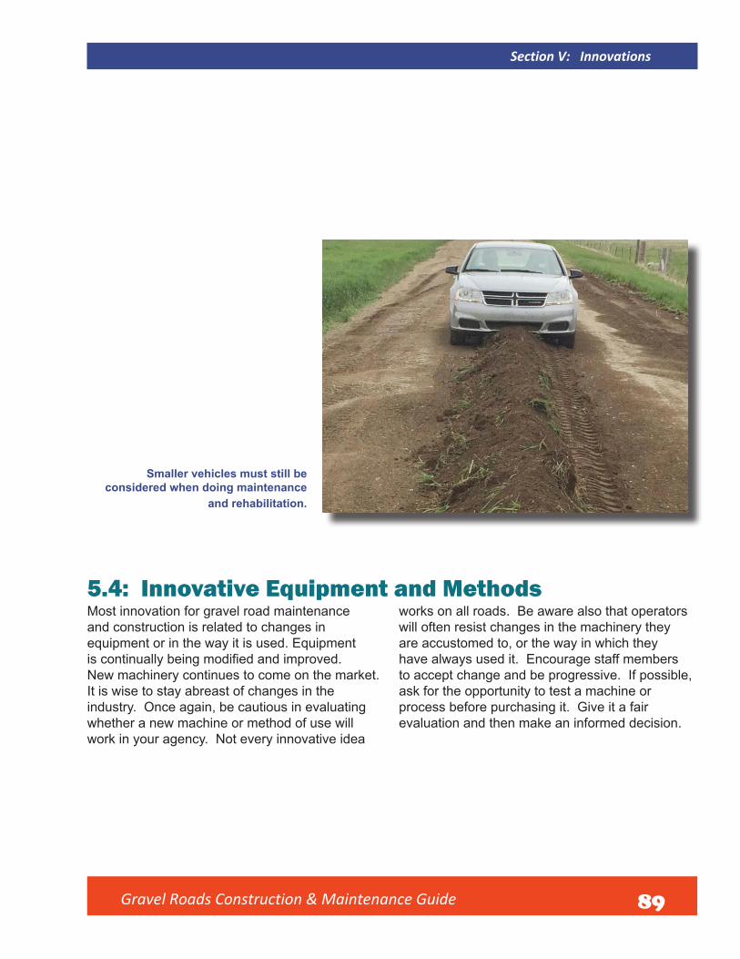
Gravel Roads Construction & Maintenance Guide 89
Section V: Innovations
Smaller vehicles must still be considered when doing maintenance
and rehabilitation.
5.4: Innovative Equipment and MethodsMost innovation for gravel road maintenance and construction is related to changes in equipment or in the way it is used. Equipment is continually being modified and improved. New machinery continues to come on the market. It is wise to stay abreast of changes in the industry. Once again, be cautious in evaluating whether a new machine or method of use will work in your agency. Not every innovative idea
works on all roads. Be aware also that operators will often resist changes in the machinery they are accustomed to, or the way in which they have always used it. Encourage staff members to accept change and be progressive. If possible, ask for the opportunity to test a machine or process before purchasing it. Give it a fair evaluation and then make an informed decision.

Gravel Roads Construction & Maintenance Guide 90
Section V: Innovations
5.5: Shouldering DisksEliminating high shoulders that develop along the edge of gravel roads is always important. Shouldering disks for use on motor graders or tractors make this job easier. The disks break up the material to reduce the size of windrows of recovered material pulled back onto the roadway. They may not work in every region, but have proven to be successful in many agencies.
Example of a shouldering disk mounted on a tractor to process sod and gravel before moving it back to the road.
5.6: Windrow PulverizersThe need to reshape a gravel road periodically to restore overall shape and drainage has been stressed. The need becomes even more urgent under heavy traffic, when the road begins to rutand fail. This often means recovering gravel and vegetation and moving it back onto the road. This could come from cleaning a ditch or simply eliminating a high shoulder. Sometimes, the material has to be removed and loaders and excavators may be needed. But sometimes the material is primarily recovered gravel that needs to be recycled and reused on the road. How do you deal with clumps of sod that come with it? In the past, this was usually accomplished by working the material back and

Gravel Roads Construction & Maintenance Guide 91
Section V: Innovations
forth across the road with motor graders. It requires many passes to do this. Farm disks are sometimes used to assist in breaking up clumped material, but again multiple passes are necessary. Commercially marketed machines that are designed to quickly pulverize and mix the material are available. It makes the job quicker, easier, and safer due to less time spent on the roadway while maintaining traffic.
Reshaping, or reconstructing a gravel road requires
processing of very large windrows of material.
Examples of two commercially marketed pulverizers on
the market which speed the gravel reclaiming process.

Gravel Roads Construction & Maintenance Guide 92
Section V: Innovations
Recycling and milling equipment for pavement rehabilitation can also be used to pulverize and mix reclaimed gravel.
If possible, multiple uses for equipment should be considered.

Gravel Roads Construction & Maintenance Guide 93
Section V: Innovations
5.7: Moldboard Cutting Edge OptionsConventional cutting edges still work well. But, there have been several types of carbide-tipped bits adapted for use on the moldboards of graders.
The bits allow an operator to cut out a washboard area or loosen hard surface material with much less time and effort than a conventional cutting edge. The bits also do some mixing of material as it is cut from the road. They do not work for every situation in maintenance but will perform very well in many maintenance and rehabilitation functions.
Carbide-insert cutting edges are also available. Although expensive, they are extremely resistant to abrasive wear and are a great help in reducing center wear on the cutting edge.
Carbide-tipped bits are very resistant to breakage, while inserts are not as resistant. Choose what best suits the conditions in your agency.
Examples of carbide-tipped bits on a moldboard
cutting edge and on a tool bar mounted on the
front of the grader.

Gravel Roads Construction & Maintenance Guide 94
Section V: Innovations
Example of carbide-insert in a cutting edge with hard facing on the bottom of the
face to increase wear life.
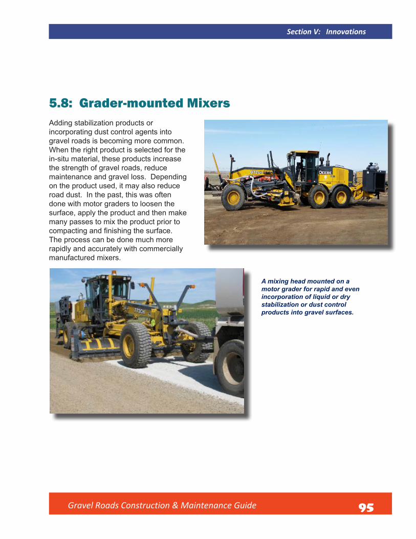
Gravel Roads Construction & Maintenance Guide 95
Section V: Innovations
5.8: Grader-mounted MixersAdding stabilization products or incorporating dust control agents into gravel roads is becoming more common. When the right product is selected for the in-situ material, these products increase the strength of gravel roads, reduce maintenance and gravel loss. Depending on the product used, it may also reduce road dust. In the past, this was often done with motor graders to loosen the surface, apply the product and then make many passes to mix the product prior to compacting and finishing the surface. The process can be done much more rapidly and accurately with commercially manufactured mixers.
A mixing head mounted on a motor grader for rapid and even incorporation of liquid or dry stabilization or dust control products into gravel surfaces.

Gravel Roads Construction & Maintenance Guide 96
Section V: Innovations
5.9: Grader-Mounted RollersIn some rural regions of the country where more space is available for turning and maneuvering the equipment, a grader-mounted roller may be feasible. It is an efficient way tocombine blading and compaction operations. When budgets are tight and personnel are not available to operate self-propelled or towed rollers, consider this attachment. When adequate moisture is present, the use of a roller on a grader will produce a tighter and smoother surface. The rollers can be used in routine maintenance and reshaping operations, and are very effective when placing new gravel.
Different types of grader-mounted rollers are available.
When moisture is present in the material being
shaped, they are an excellent tool for
basic compaction.

Gravel Roads Construction & Maintenance Guide 97
Section V: Innovations
5.10: Electronic Slope ControlsThis technology has been used in the road construction industry for many years. More recently, it has proven useful in gravel road maintenance, rehabilitation, and basic reconstruction with agency-owned equipment. It will not work in every maintenance situation, but some agencies are beginning to use electronic slope (crown) controls when doing major reshaping on gravel roads. This helps greatly in getting the proper profile established on the new surface. After shaping, new gravel is placed also using the electronic control to construct uniform layer thickness and correct profile on the finished surface.Thereafter, some agencies are beginning to use electronic controls for routine maintenance to maintain correct slope (crown) on the surface. It has drawbacks on roads with frequent change in horizontal and vertical alignment (“crooked and hilly”), but works well on roads with fairly long, straight sections with reasonably uniform width.
Two examples of screens in the grader cab showing electronic slope controls being used to construct at or near 4 percent crown, or cross-slope, on the road surface.

Gravel Roads Construction & Maintenance Guide 98
Section V: Innovations
5.11: Tractor-Mounted or Towed Blading DevicesSimple blades attached to tractors have been used for a long time. But the concept has been improved. These devices are not capable of aggressive shaping or handling large windrows of material as can be done with a motor grader. However, they can handle enough gravel to fill smallpotholes and depressions. Depending on the weight and control of the device, minor change in shape of the road surface can be done. The use of these devices should be approached as a supplement to maintenance with a motor grader and not to replace the grader. Skillful use of these will allow the performance of light maintenance and leveling, particularly in wet conditions where a motor grader will be too heavy to work without sinking into surface.
Example of a light blading device being towed by a mower tractor.
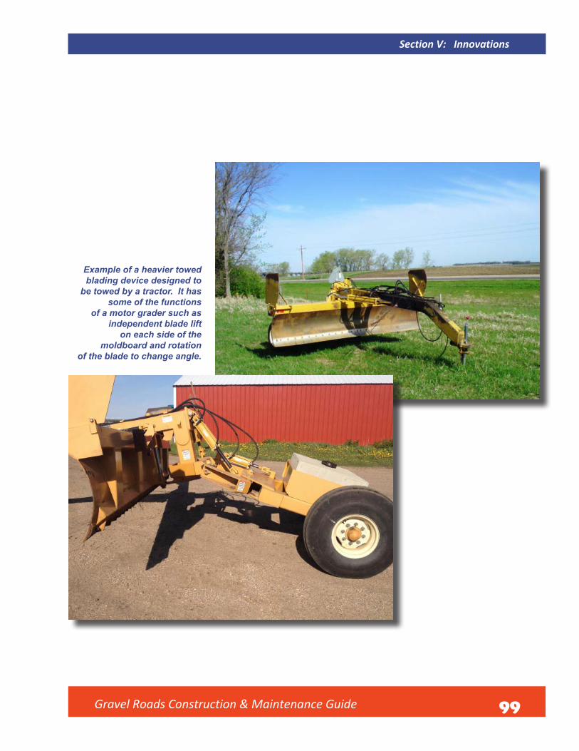
Gravel Roads Construction & Maintenance Guide 99
Section V: Innovations
Example of a heavier towed blading device designed to
be towed by a tractor. It has some of the functions
of a motor grader such as independent blade lift
on each side of the moldboard and rotation
of the blade to change angle.

Gravel Roads Construction & Maintenance Guide 100
Section V: Innovations
5.12: Tractor-Mounted CrushersIn many regions, native soil is simply shaped into a basic cross section to create a road to drive on. The soil will often contain large rocks that cannot used on the surface. It is costly to remove them. In other cases, the subgrade material will be made up almost entirely of rock or very coarse aggregate. In yet other cases, failing asphalt surfaces cannot be maintained or reconstructed. Yet, the material could be used as gravel surfacing if ripped and mixed with base aggregate. Rocky material can also be used as surfacing if it can be economically crushed and processed into a uniform sized product suitable for surface aggregate. Small crushers capable of doing this in-place on the road surface without removing it to a central plant site are coming on the market. This may work in your agency.
An example of a tractor-mounted crusher processing coarse material in-place.

101
Summary
The first and most basic thing to understand in road maintenance and construction is proper shape ofthe cross section. The road surface must have enough crown to drain water to the shoulder, but not excessive crown which impacts roadway safety. Next, the shoulder area must not be higher than the edge of the traveled way on the road surface. A high shoulder prevents water from draining to the ditch and, therefore, needs to be eliminated. Finally, a ditch must be established and maintained to drain water away from the roadside. Culverts and bridges at the right location and elevation are essential for carrying water under and away from the road.
Once the correct shape and adequate drainage is established on a roadway, attention must be given to obtaining and properly placing good gravel. It is very important to understand the makeup of good gravel. Simply stated, it is a proper blend of stone, sand and fine-sized particles. Materials vary greatly from region to region, but it is wise to use the best material available. Gravel must also be handled properly. Avoiding segregation of material while processing and handling it is important to maintain the quality of gravel. Careful calculation of the volume of material and allowing for shrinkage from compaction is also needed to get the desired depth of surfacing on the road. Due to severe budget constraints that are common in the management of gravel roads, compaction is often minimal or not done at all. If at all possible, it is highly recommended that water be used to reach optimum moisture and compaction be done when placing new a new layer of gravel. The cost of doing this will often be offset by better performance of the surface in the initial period after placement.
When proper shape is established and good surface gravel is placed, many gravel road maintenance problems simply go away and road users are provided the best possible service from gravel roads.
Gravel Roads Construction & Maintenance Guide

Gravel Roads Construction & Maintenance Guide
Tools:Figures, Tables, & Charts
Reference Page
FIGURE 1: Roadway cross section. The components of the roadway cross section 1FIGURE 2: Moldboard pitch. Moldboard pitch or “tilt” refers to how much the moldboard is tipped forward
backward. The right pitch ranges from aggressive cutting (1), to spreading (2), to light blading or dragging action (3) for maintenance of gravel roads.
7
FIGURE 3: Articulated Motorgrader. Illustration of an articulated motor grader and definitions of termsspecific to the moldboard.
9
FIGURE 4: Roadway with a parabolic crown. The outer edge of the roadway slope too much due to gouging at the edges while the center of the road remains quite flat.
13
FIGURE 5: Cutting edge center wear. Illustration of center wear in a cutting edge which leads to parabolic shape on the road surface.
14
FIGURE 6: Correct crown 14FIGURE 7: Proper shape of a controlled intersection. 31FIGURE 8: Proper shape of an uncontrolled intersection. 31FIGURE 9: Illustration of a gravel road intersecting a paved road. Gradually, eliminate the crown on
the gravel road to match the edge of pavement.32
FIGURE 10: Crown to superelevation transition. Illustration of the transition from a normal crown to the superelevated shape needed in a curve.
35
FIGURE 11: Improper matching of driveway and public road. 36FIGURE 12: Proper matching of driveway and public road. 36FIGURE 13: Testing aggregate gradation. Illustration of stack of sieves used to test aggregate gradation. 61FIGURE 14: Reshaped Gravel Road Profile Example 106FIGURE 15: Roadway Layers 106FIGURE 16: Sieve Analysis and P.I. Worksheet - South Dakota DOT 110FIGURE 17: Gravel Road Maintenance Cost Per Mile 121FIGURE 18: Paving Options 121FIGURE 19: Impacts of Gravel Surfaces on User Costs 122FIGURE 20: Walk Around Inspection Diagram 126FIGURE 21: Motorgrader Preventative Maintenance Checklist 127
Table 1: Example of Gradation Requirements & Plasticity for Two Types of Materials 63Table 2: U.S. Customary Roadway Width Table 104Table 3: Thickness Design Guidance for New or Reconstructed Rural Roads 107Table 4: Surface Aggregate Sample Specification 107
CHART 1: Surface Gravel Quality Comparison - Difference in Volume of Loose Aggregate Measured in South Dakota Surface Gravel Quality Comparison Test
65
CHART 2: Gravel Spread Chart - Truck Capacity in Cubic Yards 113CHART 3: Gravel Spreading Chart - Feet per truckload 113
102

Gravel Roads Construction & Maintenance Guide 103
Appendix A:
Construction Guidelines

Appendix A: Construction Guidelines
Overview:
Gravel roads are often constructed or rehabilitated without a formal project plan or specifications to control the work. The work is generally performed with agency staff and equipment. Consequently, the knowledge, experience and skills of field supervisors and workers is critical to manage the work in a way that will result in an improved road. While it is not common practice, it is good to get engineering advice and assistance if at all possible. The level of funding for gravel road improvement is often very limited, which allows only basic improvements to be made. Consequently, guidance in this Appendix will be limited to basic concepts that can understood and followed by field staff. Whether formal or informal, a plan must be in place and understood by management and field staff before the work begins.
Standards: If the agency has established standard requirements for roadway geometry, such as surface width, steepness of foreslopes and backslopes, and minimum horizontal and vertical alignment requirements, be sure to follow them. If local standards do not exist, check local road standards established by your State department of transportation. There may be constraints that prevent meeting those standards. One example would be inadequate public right-of-way in which to build a good cross section and no opportunity to purchase additional right-of-way. At this point, some basic risk assessment needs to be done to determine how to proceed. If deviation from local or State standards is necessary, discuss and document why this was done before beginning the project.
APPENDIX A: Construction Guidelines A1
If no local or State standards are available, one resource is A Policy on Geometric Design of Highways and Streets, often called the “Green Book”, published by AASHTO. Look in the section on local roads for guidance. Another good resource is Guidelines for Geometric Design of Very Low-Volume Local Roads (ADT ≤ 400) also published by AASHTO. Note the guidance in that manual applies only to those roads with average traffic volume of 400 vehicles per day or less. The vast majority of gravel roads have traffic volume that fits that traffic volume requirement less than 400 ADT.
U.S. Customary Total roadway width (ft) by functional subclass
Design speed (mph)
Major access
Minor access
Recre-ational
and scenic
Industrial/ com-
mercial access
Resource Recovery
Agri-cultural access
15 - 18.0 18.0 20.0 20.0 22.0 20 - 18.0 18.0 20.0 20.0 24.0 25 18.0 18.0 18.0 21.0 21.0 24.0 30 18.0 18.0 18.0 22.5 22.5 24.0 35 18.0 18.0 18.0 22.5 22.5 24.0 40 18.0 18.0 20.0 22.5 - 24.0 45 20.0 20.0 20.0 23.0 - 26.0 50 20.0 20.0 20.0 24.5 - - 55 22.0 - 20.0 - - - 60 22.0 - - - - -
Note: Total roadway width includes the width of both traveled way and shoulders.
Table 2: Total roadway width This table provides guidance on recommended roadway width for very low volume roads according to road subclassification. Source: Guidelines for Geometric Design of Very Low-Volume Local Roads (ADT ≤ 400) 1st Edition Managing Construction or Rehabilitation of Gravel Roads.
104 Gravel Roads Construction & Maintenance Guide

Gravel Roads Construction & Maintenance Guide 105
Establish right-of-way lines and construction lines boundaries well in advance of the work. Contact utility companies for location of all utilities within the project area or for verification that none exist within the boundaries of the construction area. Arrange for relocation of utilities if needed.
Bridges, culverts, and other drainage structures must be inspected on rehabilitation projects and repaired or replaced if necessary. The same must be installed ahead of time when doing new construction.
Sediment control needs to be addressed such as placing leaving vegetative buffers, silt fence, inlet protection for culverts and other controls as necessary. Be especially careful near lakes, swamps, or streams. Erosion control needs to be considered as well. This could include placing, erosion control blanket, erosion control wattles, and erosion bales and seeding after construction to hold soil in place.
Before construction or rehabilitation work begins, be sure that proper work zone traffic control devices are in place. See Appendix F for guidance.
Vegetation and top soil covering gravel to be recovered should be removed and windrowed or stockpiled if possible and then placed back on slopes and ditches when construction is finished. The area outside of the limits of construction should not be disturbed.
Trees, stumps, roots, large rocks and other obstructions need to be cleared and removed. Branches of trees extending over the roadbed must be trimmed to give adequate clearance above the roadbed surface when finished.
Dig-outs and removal and disposal of saturated organic mixtures of soils and organic matter as well as rock excavation may have to be done before construction or rehabilitation begins.
When construction of the new road surface begins, material shall be placed in horizontal layers, generally not exceeding a loose depth of 4 inches. If larger compaction equipment is available, layers up to 8 inches could be placed.
Water needs to be hauled and applied as needed. Work to get optimum moisture in the material in order to get maximum density and stability in the reconstructed roadbed. If material is too wet, it needs to be processed and dried down to optimum.
Some sod or chunks of cohesive soil may have to be processed. These should be thoroughly disked and pulverized. A disk designed for construction purposes is an excellent tool to have on the job. In addition, a disk helps in thoroughly mixing soil or recovered gravel to build a better road.
Compaction of material is critical. Sheepsfoot or pad drum rollers are good in soils that are predominantly clay or fine material. Pneumatic(rubber tired) rollers are adequate in sandy or granular soils.
The new road surface must match existing driveways, field and farm entrances The reconstructed surface should be finished to within± 0.5% of the typical section cross slope (crown that will be established on the final gravel surface.
A2 APPENDIX A: Construction Guidelines

Gravel Roads Construction & Maintenance Guide 106
Backslope: no steeper than soil stability will
support and as flat as a R-O-W width allows.
Foreslope: recommended at 1V:3H slope or flatter
if R-O-W width allows, never steeper than 1V:2H
4% crown
FIGURE 14: A basic example of what the profile of a reshaped gravel road should look like.
Prepared subgrade
FIGURE 15: Roadway Layers: Example of building base and surface layers on a reconstructed gravel road. This may not be affordable, but will serve very well if significant truck traffic is expected.
If base gravel is placed first, it should meet a State specification. An ideal construction method is to build adequate base depth to carry the anticipated loads and then place a layer of surface gravel as a wearing course. The surface layer should be three inches minimum depth in order to have enough material for blade maintenance.
Quite often, only surface gravel is placed after construction or rehabilitation. If analysis and design by an engineer cannot be done, a basic reference to help determine suitable gravel depth taking into consideration the subgrade soil support condition and anticipated truck traffic is shown on page 107.
A3
Constructing a New Surface Gravel
APPENDIX A: Construction Guidelines
A flat bottom ditch is recommended if R-O-W
width allows.
Base aggregate layer with sufficient
thickness to support anticipated loads.

A4 APPENDIX A: Construction Guidelines
Gravel Roads Construction & Maintenance Guide 107
Table 3: Thickness Design Guidance for New or Reconstructed Rural Roads.
This table is a good guide for determining gravel layer thickness by considering subgrade support condition and projected daily volume of heavy trucks.
Surface gravel should meet a specification for its purpose which is to carry traffic and remain reasonably stable in wet or dry conditions. Many States do not have surface gravel (aggregate) specifications. The agency needs to work with suppliers to get suitable material for surfacing. It must be acknowledged that gravel surfaces will never perform like pavements. Some loose aggregate, rutting and some corrugation may form in the best gravel when exposed to heavy traffic and prolonged wet or dry conditions. Use the best material that can be obtained to improve gravel road performance.
Table 4: Surface Aggregate Sample Specifications
Annual precipitation > 20 inches < 20 inches Sieve Percent Passing Percent Passing 1” (25.0 mm) 100 3/4” (19.0 mm) 100 No. 4 (4.75 mm) 45 - 70 50 - 78 No. 8 (2.36 mm) 27 - 55 37 - 67 No. 40 (425 mm) 10 - 28 13 - 35 No. 200 (75 mm) 3.0 - 12.0 8.0 - 15.0 Liquid Limit Max 25 30 Plasticity Index 3 - 10 8 - 15

Gravel Roads Construction & Maintenance Guide 108
Guidance on Placing Gravel Before surface gravel placement begins, be sure that proper work zone traffic control devices are inplace. See Appendix F for guidance.
Calculate the desired thickness for the surface layer(s). Mark the length of road over which each load is to be spread in order to get uniform finished layer thickness Guidance on this is provided in Appendix C and a photo on page 72 shows this being done.
Prior to placing the new gravel, the motor grader operator should windrow and equalize the gravel in order to properly blend any segregated material and create an even windrow that can be spread at a uniform depth over the road surface.
If total layer thickness will exceed 4-inches, the gravel should be placed in separate layers in order to achieve good compaction and density.
Apply water as needed. If the gravel becomes too wet during construction to achieve good density
and stability, work it with graders until the moisture content is reduced enough to provide good density and stability while finishing the surface laye .
Apply compaction if at all possible. Pneumatic (rubber tired) rollers operated with tire pressures and wheel loads within the manufacturer’s recommended range are the most common means of compaction. Smooth steel drum rollers will work as well, but may cause problems if the gravel has high plasticity causing it to stick to the roller.
If the opportunity to apply compaction is not available, the dump trucks should reduce speed and stagger their tracks to help in compaction. Motor graders can be used to apply wheel compaction as well. Even the water truck can be used to aid in compaction.
Finish to the recommended crown as discussed in Section I of this manual at or near 4% cross slope, which is 1/2-half inch drop per foot on each side of the road.
APPENDIX A: Construction Guidelines A5

109
Appendix B:
Gradation and P.I. Determination
Gravel Roads Construction & Maintenance Guide

Gravel Roads Construction & Maintenance Guide 110
Gradation and P.I. DeterminationAppendix B:
FIGURE 16: Standard Analysis Sheet from the South Dakota Department of Transportation (16)
B1APPENDIX B: Gradation and P.I. Determination
111 Gravel Roads Construction & Maintenance Guide
Key to Screen Analysis and P.I. Worksheet
1. This is important data, especially for the sake ofothers, who may use the information in the future.Proper data when submitting the sample for testing iscritical. Too often, certain information is missing fromthe heading of the analysis worksheet. Always checkto see that the information is correct.
2. This section, along with the next section gives thebreak-down of size (gradation) of the material. Thisalone tells alot about material. Is it too coarse orfine, or is the blend of stone, sand, and fines wrong?Notice that the top section of gradation shows allmaterial retained on the #4 sieve and larger. This isthe stone size category.
3. The bottom left section gives the gradation break downof sand sized particles on the appropriate sieves from#8 through #80 as well as the percentage of fineswhich will pass the #100 or #200 sieves.
4. This section is important in determining the stabilityor strength that the material will have when used asa base material and also the “binding characteristic”that material will have as surface gravel. The PI orplasticity index is of particular importance. Surface
gravel needs a minimum plasticity index of 3 to assure a small percentage of true clays for binder. Good base gravel needs no plasticity and ideally should be clean and drainable to retain strength for supporting the pavement above it.
5. This section is not as important for base or surfacematerials, but is critical in determining the quality ofmaterial for making asphalt concrete since it shows thedurability or “soundness” of aggregate. However, insome regions where aggregate is known to be poor,this test is good even for surface gravel.
6. This final section is very important when testingmaterial for use in asphalt or base. However, it canbe very useful even in testing base or surface gravelbecause it shows what percentage of the stone hasat least one fractured face. When crushing pit runtype gravels, many of the small, natural stones willgo through the crushing plant without being fractured.Gravel has more strength when there are morecrushed particles since they will interlock better withthe particles surrounding them. Natural stone with arounded shape will tend to shift and move under loadsmore easily.
B2 APPENDIX B: Gradation and P.I. Determination

Gravel Roads Construction & Maintenance Guide112
Appendix C:
Quantity Calculations

Appendix C: Quantity Calculations
GRAVEL SPREAD CHART TRUCK CAPACITY IN CUBIC YARDS
Chart 2: Gravel Coverage Chart Showing Depth of Gravel in Inches** (width of road in feet)
Yd3/mi 10 12 14 16 18 20 22 24 26 400 132 158.4 184.8 211.2 237.6 264 290.4 316.8 343.2 500 105.6 126.7 147.84 168.96 190.08 211.2 232.32 253.44 274.56 600 88 105.2 123.2 140.8 158.4 176 193.6 211.2 228.8 700 75.429 90.514 105.6 120.69 135.77 150.86 165.94 181.03 196.11 800 66 79.2 92.4 105.6 118.8 132 145.2 158.4 171.6 900 58.667 70.4 82.133 93.867 105.6 117.33 129.07 140.8 152.53
1000 52.8 63.36 73.92 84.48 95.04 105.6 116.16 126.72 137.28 1100 48 57.6 67.2 76.8 86.4 96 105.6 115.2 124.8 1200 44 52.8 61.6 70.4 79.2 88 96.8 105.6 114.4 1300 40.615 48.738 56.862 64.985 73.108 81.231 89.354 97.477 105.6 1400 37.714 45.257 52.8 60.343 67.886 75.429 82.971 90.514 98.057 1500 35.2 42.24 49.28 56.32 63.36 70.4 77.44 84.48 91.52 2000 26.4 31.68 36.96 42.24 47.52 52.8 58.08 63.36 68.64 2500 21.12 25.344 29.568 33.792 38.016 42.24 46.464 50.688 54.912 3000 17.6 21.12 24.64 28.16 31.68 35.2 38.72 42.24 45.76 3500 15.086 18.103 21.12 24.137 27.154 30.171 33.189 36.206 39.223 4000 13.2 15.84 18.48 21.12 23.76 26.4 29.04 31.68 34.32 4500 11.733 14.08 16.427 18.773 21.12 23.467 25.813 28.16 30.507 5000 10.56 12.672 14.784 16.896 19.008 21.12 23.232 25.344 27.456 5500 9.6 11.52 13.44 15.36 17.28 19.2 21.12 23.04 24.96 6000 8.8 10.56 12.32 14.08 15.84 17.6 19.36 21.12 22.88 6500 8.1231 9.7477 11.372 12.997 14.622 16.246 17.871 19.495 21.12 7000 7.5429 9.0514 10.56 12.069 13.577 15.086 16.594 18.103 19.611 7500 7.04 8.448 9.856 11.264 12.672 14.08 15.488 16.896 18.304 8000 6.6 7.92 9.24 10.56 11.88 13.2 14.52 15.84 17.16
Note: To calculate the exact spread divide 5280 by the Cubic Yards per mile and multiply by the truck capacity in cubic yards.
C1APPENDIX C: Quantity Calculations
113 Gravel Roads Construction & Maintenance Guide

Truck Capacity in Cubic Yards
Chart 3: Gravel Spreading Chart in feet per truckload
(This chart originally provided to the South Dakota LTAP by Scott Construction of Lake Dalton, WI.)
Yd3/mi 5 6 6.5 7 10 12 400 66 79.2 85.8 92.4 132 158.4 500 52.8 63.4 68.6 73.9 105.6 126.8 600 44 52.8 57.2 61.6 88 105.6 700 37.7 45.3 49 52.8 75.4 90.6 800 33 39.6 42.9 46.2 66 79.2 900 29.3 35.2 38.1 41 58.6 70.4 1000 26.4 31.7 34.3 36.9 52.8 63.4 1100 24 28.8 31.2 33.6 48 57.6 1200 22 26.4 28.6 30.8 44 52.8 1300 20.3 24.4 26.4 28.4 40.6 48.8 1400 18.9 22.6 24.6 26.4 37.8 45.2 1500 17.6 21.1 22.9 24.6 35.2 42.2 2000 13.2 15.8 17.2 18.5 26.4 31.6 2500 10.6 12.7 13.8 14.8 21.2 25.4 3000 8.8 10.6 11.4 12.3 17.6 21.2 3500 7.5 9.1 9.8 10.6 15 18.2 4000 6.6 7.9 8.6 9.2 13.2 15.8 4500 5.9 7 7.7 8.2 11.8 14 5000 5.3 6.3 6.9 7.4 10.6 12.6
C2 APPENDIX C: Quantity Calculations
Gravel Roads Construction & Maintenance Guide 114
115
Appendix D:
When to Pave a Gravel Road
Gravel Roads Construction & Maintenance Guide

Gravel Roads Construction & Maintenance Guide
APPENDIX D: When to Pave a Gravel Road D1
Appendix D:When to Pave a Gravel Road*by Kentucky Transportation Center, University of Kentucky at Lexington, KY
Contents
• A Word About the Term “Paved”
• Introduction
• Gravel or Paved: A Matter of Trade-offs
• When Should We Pave This Gravel Road? A Ten Part Answer
1. After Developing a Road Management Program
2. When the Local Agency Is Committed to Excellence
3. When Traffic Demands It
4. After Standards Have Been Adopted
5. After Considering Safety and Design
6. After the Base and Drainage Are Improved
7. After Determining the Costs of Road Preparation
8. After Comparing Pavement Life and Maintenance Costs
9. After Comparing User Costs
10. After Weighing Public Opinion
• Stage Construction
• Summary
• References
*Gravel as used here may refer to sand and gravel, or to crushed stone.
116

117 Gravel Roads Construction & Maintenance Guide
A Word about the Term “Paved”What is meant by a “paved” road? For some, a light chip seal coat is considered paving. For others, paving is four or more inches of bituminous asphalt or “hot mix.” The primary purpose of a pavement is to protect the subgrade. As the loads get heavier, the pavement thickness must be increased.
Generally speaking, bituminous concrete (hot mix asphalt) has little real load-bearing capacity of its own until it reaches a thickness of 2 inches. In fact, the Asphalt Institute has a firm policy of recommending a minimum pavement thick-ness of 4 inches full depth asphalt or 3 inches asphaltic concrete plus a suitable granular base even for low volume roads. Their research shows that 4 inches of hot mix will carry about 10 times as much traffic as 2 inches of hot mix when constructed over thin granular bases.
A pavement less than two inches thick primarily protects the base materials by shedding water and providing a smooth riding surface. Such a road is more properly called a surface treated road. Roads with thin pavements must have excel-lent drainage designed into them and be diligently main-tained throughout their service life.
In this paper we will consider even a light surface treatment as paving, however. The assumption is that, when a town first applies a chip seal treatment, for example, it has taken a first step toward eventually achieving a load-bearing pavement.
IntroductionTwo-thirds of the highway systems in the United States and more than 90 percent of all the roads in the world are un-surfaced or lightly surfaced low volume roads. In Kentucky, more than 19,000 miles of local roads have gravel surfaces. Most local roads were not designed with the same consider-ations used in the design of state and interstate highways.
Most have evolved from primitive trails. Paths of least resistance first created by wild animals were later used by settlers. As needs and traffic increased, these traveled ways became roads which were gradually improved with gravel or crushed rock. Little engineering went into these improve-ments. Using available materials and “keeping them out of the mud” were the extent of efforts to maintain a road.
As paving occurred, the tendency was to make minor modi-fications to the foundations of the evolved road and to seal or pave the surface. As a result,many low volume roads in Kentucky now have continual maintenance problems be-cause of inadequate base support in addition to alignment and drainage problems.
To add to the problem, roads throughout Kentucky are experiencing ever-increasing weights and volumes of traffic. Population growth and tourism make traffic demands. Coal trucks and other commercial vehicles are carrying heavier loads than ever before. These higher volumes and greater weights are putting a steadily increasing strain on local road maintenance and reconstruction budgets.
Gravel or Paved: A Matter of Trade-offsThe decision to pave is a matter of trade-offs. Paving helps to seal the surface from rainfall, and thus protects the base and subgrade material. It eliminates dust problems, has high user acceptance because of increased smoothness, and can accommodate many types of vehicles such as tractor-trailers that do not operate as effectively on unsurfaced roads.
In spite of the benefits of paved roads, well-maintained gravel roads are an effective alternative. In fact, some local agencies are reverting to gravel roads. Gravel roads have the advantage of lower construction and sometimes lower maintenance costs. They may be easier to maintain, requir-
ing less equipment and possibly lower operator skill levels. Potholes can be patched more effectively. Gravel roads gen-erate lower speeds than paved surfaces. Another advantage of the unpaved road is its forgiveness of external forces. For example, today vehicles with gross weights of 100,000 pounds or more operate on Kentucky’s local roads. Such vehicles would damage a lightly paved road so as to require resealing, or even reconstruction. The damage on a gravel road would be much easier and less expensive to correct.
There is nothing wrong with a good gravel road. Properlymaintained, a gravel road can serve general traffic adequately for many years.
D2 APPENDIX D: When to Pave a Gravel Road

Gravel Roads Construction & Maintenance Guide 118
Should We Pave This Gravel Road? A Ten Part AnswerWhen a local government considers paving a road, it is usually with a view toward reducing road maintenance costs and providing a smooth riding surface. But is paving always the right answer? After all, paving is expensive. How does a county or city know it is making the most cost-effective decision?
We will consider ten answers to the question, “Should we pave this gravel road?” In fact they are ten parts of oneanswer. If one of the ten is not considered, the final deci-sion may not be complete. The ten answers taken together provide a framework for careful decision making.
Answer 1: After Developing a Road Management ProgramIf the road being considered for paving does not fit into acountywide road improvement program, it is quite possiblethat funds will not be used to the fullest advantage. The goal of a road management system is to improve all roads or streets by using good management practices. A particularroad is only one of many in the road system.
A road management system is a common sense, step-by-step approach to scheduling and budgeting for road mainte-nance work. It consists of surveying the mileage and condi-tion of all roads in the system, establishing short-term and long-term maintenance goals and prioritizing road projects according to budget constraints.
A road management system helps the agency develop itsroad budget and allows the use of dollars wisely becauseits priorities and needs are clearly defined.
Through roadway management, local governments candetermine the most cost-effective, long-term treatments for their roads, control their road maintenance costs, and spend tax dollars more wisely. Local governments that stick with the program will be rewarded with roads that are easier and less costly to maintain on a yearly basis. Perti-nent information about all roads will be readily available for years to come instead of scattered among files or tucked away in an employee’s head.
Steps in a Road Management Program:
1. Inventory the roads. The amount of time available andthe miles of road in a county or city will determine howmuch detail to go into.
2. Assess the condition of the roads. Develop simple andeasy techniques to use each year. Maintain a continuingrecord of the assessed condition of each road so thatchanges in condition can be noted easily and quickly.
3. Select a road management plan. Select the mostappropriate treatment to repair each road, bridge, orproblem area.
4. Determine overall needs. Estimate the cost of eachrepair job using generalized average costs and tally upthe total. Establish long-range goals and objectives thatin turn will help the agency justify its budget requests.
5. Establish priorities. Keep good roads in good shape(preventive maintenance) and establish a separatebudget, or request a temporary increase, to reconstructreally bad roads.
Answer 2: When the Local Agency Is Committed to Effective ManagementA commitment to effective management is an attitude. It is a matter of making sure that taxpayers’ money is well spent—as if it were one’s own money. It does not mean paving streets with gold but it does mean using the best materials available. It does not mean taking short cuts resulting in a shoddy project but it does mean using correct construction techniques and quality control. A commitment to effective management means planning for 5 or even 10 years instead of putting a band-aid on today’s problem. It means taking the time to do things right the first time and constructing projects to last.
Consider a child’s tree house compared to a typical three bedroom house in a Kentucky town. Because each protectspeople from the wind and rain each comes under the defi-nition of a shelter. However, the tree house was built with
available materials and little craftsmanship. The other was planned, has a foundation, sound walls, a roof, and with care, can last hundreds of years. One is a shack and the other is a family dwelling. Only one was built with a commitment to excellence.
Many roads are like the tree house. They qualify under thedefinition but they are not built to last.
The horse and buggy days are over. We are in an age of travelers’ demands, increasing traffic, declining revenues and taxpayer revolts. We are expected to do more with less. Building roads to last requires an attitude of excellence. Such an attitude helps to make better decisions, saves money in the long run, and results in a better overall road system.
APPENDIX D: When to Pave a Gravel Road D3

119 Gravel Roads Construction & Maintenance Guide
Answer 3: When Traffic Demands ItThe life of a road is affected by the number of vehicles and the weight of the vehicles using it. Generally speaking, the more vehicles using a road, the faster it will deteriorate.
The average daily traffic volumes (ADT) used to justify pavinggenerally range from a low of 50 vehicles per day to 400 or500. When traffic volumes reach this range, serious consid-eration should be given to some kind of paving.
Traffic volumes alone are merely guides. Types of traffic should also be considered. Different types of traffic (and drivers) make different demands on roads. Will the road
be used primarily by standard passenger cars or will it be a connecting road with considerable truck traffic? Overloaded trucks are most damaging to paved roads.
The functional importance of the highway should also beconsidered. Generally speaking, if the road is a major road, it probably should be paved before residential or side roads are paved. On the other hand, a residential street may be economically sealed or paved while a road with heavy truck usage may best be surfaced with gravel and left unpaved un-til sufficient funds are available to place a thick load-bearing pavement on the road.
Answer 4: After Standards Have Been AdoptedWritten standards in the areas of design, construction and maintenance define the level of service we hope to achieve.They are goals to aim for. Without written standards there is no common understanding about what a local government is striving for in road design, construction and maintenance. In deciding to pave a gravel road, is the local government confident it would be achieving the desired standards?
Design and construction standards do not have to be complex. It takes only a few pages to outline such things as right-of-way width, traveled way width, depth of base, drain-age considerations (such as specifying minimum 18”culvert pipe),types of surfacing and the like.
Maintenance standards address the need for planned peri-odic maintenance. A good maintenance plan protects local roads, which for most counties represents many millions of dollars of investment. It also is an excellent aid when it comes time to create a budget.
Considerations include: How often shall new gravel be applied to a gravel road? (Some roads require it more than others do.) How many times per year are roads to be grad-ed? How often and in what locations should calcium chlo-ride or other road stabilizers be applied? What is our plan for checking road signs? (Because of legal liability, a missing sign can be very costly if not replaced.) What is our plan for ditching and shouldering?
Answer 5: After Considering Safety and DesignPaving a road tempts drivers to drive faster. As speed increases, the road must be straighter, wider, and as free as possible from obstructions for it to be safe. Paving low volume roads before correcting safety and design inadequa-cies encourages speeds which are unsafe, especially when the inadequacies “surprise” the driver. Because of the vast mileage of low volume roads, it is difficult to reduce speeds by enforcement.
Roads must be designed to provide safe travel for the expected volume at the design speed. To do this a number of physical features must be considered:
• Sight Distance • Design Speed• Alignment and Curves • Surface Friction• Lane Width • Superelevation
It may be necessary to remove trees or other obstructions such as boulders from the road’s edge. Some engineers insist that no road should be paved that is less than 22 feet wide. If this standard is accepted, gravel roads must be widened before paving. Bridges may need widening. Considering these and other safety and design factors in the early stages of decision making can help to achieve the most economical road and one that will meet transportation needs. It makes no sense to pave a gravel road which is poorly designed and hazardous.
D4 APPENDIX D: When to Pave a Gravel Road

Gravel Roads Construction & Maintenance Guide 120
Answer 6: After the Base and Drainage Are Improved“Build up the road base and improve drainage before paving.” This cardinal rule cannot be stressed enough. If the foundation fails, the pavement fails. If water is not drained away from the road, the pavement fails. Paving a road with poor base or with inadequate drainage is a waste of money. It is far more important to ask, “Does this road need strengthening and drainage work?” than it is to ask, “Should we pave this gravel road?”
Soil is the foundation of the road and, as such, it is the mostimportant part of the road structure. A basic knowledge ofsoil characteristics in the area is very helpful and can helpavoid failures and unneeded expense. Soils vary throughoutthe country. For highway construction in general, the
most important properties of a soil are its size grading, its plasticity, and its optimum moisture content.
There is a substantial difference in the type of crushed stone or gravel used for a gravel road-riding surface versus that used as a base under a pavement. The gravel road surface needs to have more fines plus some plasticity to bind it together, make it drain quicker and create a hard riding surface. Such material is an inferior base for pavement. If pavement is laid over such material, it traps water in the base. The high fines and the plasticity of the material make the wet base soft. The result is premature pavementfailure.
Answer 7: After Determining the Costs of Road PreparationThe decision to pave a gravel road is ultimately an economic one. Policy makers want to know when it becomes economical to pave.
There are two categories of costs to consider: total road costs and maintenance costs.
Local government needs to determine what the costs are toprepare a road for paving. Road preparation costs are thecosts of construction before paving actually takes place.
For example, if standards call for a traveling surface of 22 feet and shoulders of two feet for a paved road, the costs of new material must be calculated. Removing trees, brush or boulders, adding new culverts or other drainage improvements, straightening a dangerous curve, improving
slopes and elevations, constructing new guardrails, upgrading signs and making other preparations – all must be estimated.
Costs will vary greatly from project to project depending ontopography, types of soils, availability of good crushed stone or gravel, traffic demands and other factors. One important factor is the standards. That is one reason why we should carefully consider what is contained in the road policy (#4 above). For larger projects it may be desirable to hire an en-gineering consulting firm (another cost) to design the road and make cost estimations. For smaller projects construction costs can be fairly closely calculated by adding the estimated costs of materials, equipment and labor required to com-plete the job.
Answer 8: After Comparing Pavement Costs, Pavement Life and Maintenance CostsA second financial consideration is to compare maintenance costs of a paved road to maintenance costs of a gravel road. To make a realistic comparison we must estimate the years of pavement life (how long the pavement will be of service before it requires treatment or overlay) and the actual cost of paving. It is at this point that we can begin to actually compare costs between the two types of roads.
Consider the following maintenance options:
A. For both paved and gravel roads, a local governmentmust: maintain shoulders – keep ditches clean –clean culverts regularly – maintain roadsides (brush,grass, etc.) – replace signs and signposts.
B. PAVED roadways require: patching – resealing (chip,slurry, crack seal) and striping.
C. GRAVEL roadways require: regraveling – grading andstabilization of soils or dust control.
Since the maintenance options in “A” are common to bothpaved and gravel roads, they do not have to be consideredwhen comparing maintenance costs. These costs for eithertype of road should be about the same. But the costs ofthe maintenance options in “B” and “C” are differentand therefore should be compared.
Figure 17 shows costs for maintaining gravel roads over a 6-year period in a hypothetical situation.If records of costs are not readily available, you may use a “best guess” allowing for annual inflation costs.
Three paving options are listed in Figure 18. Each includes estimated costs for paving and an estimated pavement life. You should obtain up-to-date cost estimates and expected pavement life figures for these and other paving options by talking to your State department of transportation, contractors, and neighboring towns and counties.
APPENDIX D: When to Pave a Gravel Road D5
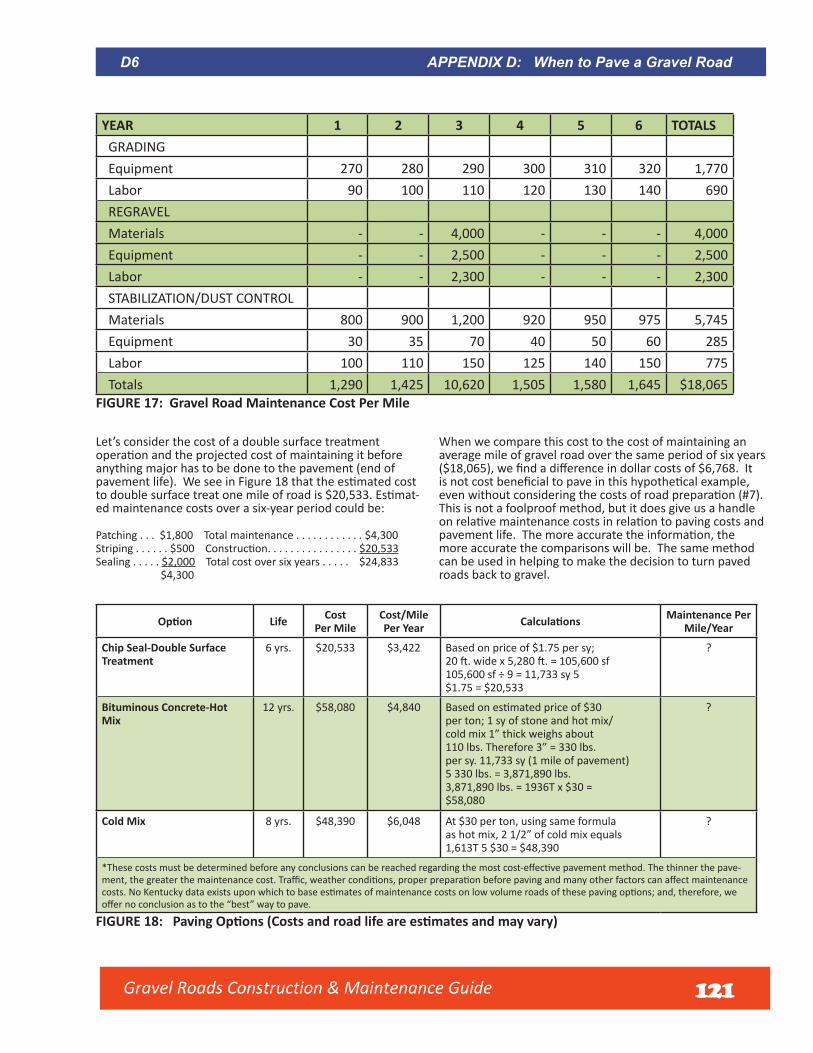
YEAR 1 2 3 4 5 6 TOTALS GRADING Equipment 270 280 290 300 310 320 1,770 Labor 90 100 110 120 130 140 690 REGRAVEL Materials - - 4,000 - - - 4,000 Equipment - - 2,500 - - - 2,500 Labor - - 2,300 - - - 2,300 STABILIZATION/DUST CONTROL Materials 800 900 1,200 920 950 975 5,745 Equipment 30 35 70 40 50 60 285 Labor 100 110 150 125 140 150 775 Totals 1,290 1,425 10,620 1,505 1,580 1,645 $18,065
FIGURE 17: Gravel Road Maintenance Cost Per Mile
Let’s consider the cost of a double surface treatment operation and the projected cost of maintaining it before anything major has to be done to the pavement (end of pavement life). We see in Figure 18 that the estimated cost to double surface treat one mile of road is $20,533. Estimat-ed maintenance costs over a six-year period could be:
Patching . . . $1,800 Total maintenance . . . . . . . . . . . . $4,300Striping . . . . . . $500 Construction. . . . . . . . . . . . . . . . $20,533Sealing . . . . . $2,000 Total cost over six years . . . . . $24,833
$4,300
When we compare this cost to the cost of maintaining anaverage mile of gravel road over the same period of six years($18,065), we find a difference in dollar costs of $6,768. It is not cost beneficial to pave in this hypothetical example, even without considering the costs of road preparation (#7).This is not a foolproof method, but it does give us a handleon relative maintenance costs in relation to paving costs andpavement life. The more accurate the information, the more accurate the comparisons will be. The same method can be used in helping to make the decision to turn paved roads back to gravel.
Option Life Cost Per Mile
Cost/Mile Per Year Calculations Maintenance Per
Mile/Year
Chip Seal-Double Surface Treatment
6 yrs. $20,533 $3,422 Based on price of $1.75 per sy; 20 ft. wide x 5,280 ft. = 105,600 sf105,600 sf ÷ 9 = 11,733 sy 5$1.75 = $20,533
?
Bituminous Concrete-Hot Mix
12 yrs. $58,080 $4,840 Based on estimated price of $30 per ton; 1 sy of stone and hot mix/cold mix 1” thick weighs about110 lbs. Therefore 3” = 330 lbs.per sy. 11,733 sy (1 mile of pavement)5 330 lbs. = 3,871,890 lbs.3,871,890 lbs. = 1936T x $30 =$58,080
?
Cold Mix 8 yrs. $48,390 $6,048 At $30 per ton, using same formula as hot mix, 2 1/2” of cold mix equals1,613T 5 $30 = $48,390
?
*These costs must be determined before any conclusions can be reached regarding the most cost-effective pavement method. The thinner the pave-ment, the greater the maintenance cost. Traffic, weather conditions, proper preparation before paving and many other factors can affect maintenance costs. No Kentucky data exists upon which to base estimates of maintenance costs on low volume roads of these paving options; and, therefore, we offer no conclusion as to the “best” way to pave.
FIGURE 18: Paving Options (Costs and road life are estimates and may vary)
D6 APPENDIX D: When to Pave a Gravel Road
Gravel Roads Construction & Maintenance Guide 121

Answer 9: After Comparing User CostsNot all road costs are reflected in a highway budget. There is a significant difference in the cost to the user between driving on a gravel surface and on a paved surface. User costs, therefore, are appropriate to consider in the pave/not pave decision. By including vehicle-operating costs with construction and maintenance costs, a more comprehensive total cost can be derived.
Vehicles cost more to operate on gravel surfaces than on paved surfaces, often 2 or 3 times greater than for bitumi-nous concrete roads in the same locations. There is greater rolling resistance and less traction which increase fuel consumption. The roughness of the surface contrib- utes to additional tire wear and influences maintenance and repair expenses. Dust causes extra engine wear, oil consumption and maintenance costs. Figure 19 from AASHTO’S “A Manual on User Benefit Analysis of Highway and Bus-Transit Improvements” shows the impacts of gravel surfaces on user costs. For example, an average run-ning speed of 40 MPH on a gravel surface will increase the user costs of passenger cars by 40% (1.4 conversion factor). The general public is not aware that their costs would actu-ally be less if some of these roads were surface treated.
Add to the gravel road maintenance the user costs over a 6-year period. Estimate an average daily traffic (ADT) of100 cars and 50 single unit trucks, traveling at 40 mph.Estimate that it costs $.25 per mile to operate the vehicleson pavement. Using the chart in Figure 3, we see it costs1.4 times as much (or $.35) to drive a car 40 mph one mileon gravel road and 1.43 times as much (or $.36) to drive asingle unit (straight frame) truck 40 mph one mile on gravelroad.
100 cars x 365 days x $.10 added cost x 1 mile = $3,65050 trucks x 365 days x $.11 added cost x 1 mile = $2,008
User costs for the gravel road is $5,659 per year or $33,954 for a 6-year period. Assuming we still do not consider road preparation costs, it now appears justified to pave the road. Such an approach can be used to establish a “rule of thumb” ADT. For example, some agencies give serious consideration to paving roads with an ADT above 125.
Conversion factor -- to earth surfaces
Speed - MPH
Source: Winfrey (4) page 72 SA-3334-%
3-S2 Trucks
Single Unit Trucks
Passenger Cars
2.4
2.2
2.0
1.6
1.5
1.4
1.2
1.00 5 10 15 20 25 30 35 40 45 50 55 60
1.7
.6
.5
.4
.3
.2
.1
1.0
Con
vers
ion
fact
or --
to g
rave
l and
sto
ne s
urfa
ces
To use this chart, determine the type of vehicle, the speed and the type of road surface. Follow the speed line vertically to the vehicle type. Go horizontally to multiplier factor of road surface. Multiply the cost of travelling on a paved surface by this number to determine the cost of operating the same vehicle on gravel surface or dirt surface. Example: If it costs 28¢ per mile to operate a passenger car* at 40 mph on pavement, it will cost 39¢ per mile to operate it on a gravel road at the same speed and 50¢ per mile on a dirt road.
*1984 Federal Highway Administration Statistics quotes an operating cost of 28¢ per mile for an intermediate size passenger car traveling on average suburban pavement. You must determine your own vehicle operating costs on pavement in order to use these multiplicative factors to calculate. Public opinion as to whether to pave a road can be revealing, but it should not be relied upon to the exclusion of any one of points 1-9 already discussed. If a decision to pave is not based on facts, it can be very costly. Public opinion should not be ignored, of course, but there is an obligation by government leaders to inform the public about other important factors before making the decision to pave.
FIGURE 19: Impacts of Gravel Surfaces on User Costs
Gravel Roads Construction & Maintenance Guide 122
Answer 10: After Weighing Public OpinionPublic opinion as to whether to pave a road can be revealing, but it should not be relied upon to the exclusion of any one of points 1-9 already discussed. If a decision to pave is not based on facts, it can be very costly. Public
opinion should not be ignored, of course, but there is an obligation by government leaders to inform the public about other important factors before making the decision to pave.
APPENDIX D: When to Pave a Gravel Road D7
Stage ConstructionLocal government may consider using “stage constructiondesign” as an approach to improving roads. This is how itworks. A design is prepared for the completed road, from base and drainage to completed paving. Rather than accom-plishing all the work in one season, the construction is spread out over 3- to 5-years. Paving occurs only after the base and drainage have been proven over approximately 1 year. Crushed gravel treated with calcium chloride serves as the wearing course for the interim period. Once all weak spots have been repaired, the road can be shaped for paving.
There are some advantages to keeping a road open to trafficfor one or more seasons before paving:
1. Weak spots that show up in the sub-grade or base canbe corrected before the hard surface is applied, elimi-nating later expensive repair;
2. Risky late season paving is eliminated;3. More mileage is improved sooner;4. The cost of construction is spread over several years.
Note: Advantages may disappear if timely maintenance is not performed. Surface may deteriorate more rapidly because it is thinner than a designed pavement.
SummarySome local roads are not well engineered. Today, larger volumes of heavy trucks and other vehicles are weakening them at a fast rate. Paving roads as a sole means of improv-ing them without considering other factors is almost always
a costly mistake. Counties and cities should consider these ten points first. Carefully considering them will help to assure local government officials that they are making the right decision about paving a gravel road.
D8 APPENDIX D: When to Pave a Gravel Road
Gravel Roads Construction & Maintenance Guide 123
Gravel Roads Construction & Maintenance Guide
Appendix E:
Walk-around Grader Inspection
124
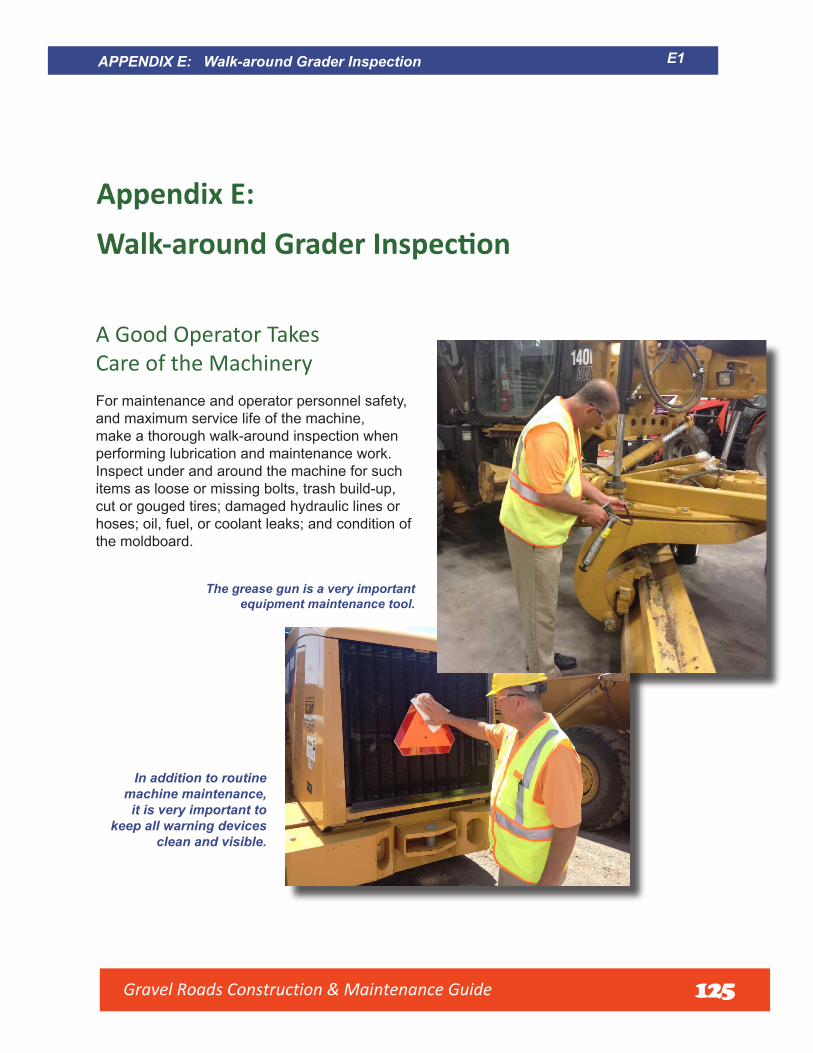
E1APPENDIX E: Walk-around Grader Inspection
Appendix E:Walk-around Grader Inspection
A Good Operator Takes Care of the Machinery For maintenance and operator personnel safety, and maximum service life of the machine, make a thorough walk-around inspection when performing lubrication and maintenance work. Inspect under and around the machine for such items as loose or missing bolts, trash build-up, cut or gouged tires; damaged hydraulic lines or hoses; oil, fuel, or coolant leaks; and condition of the moldboard.
The grease gun is a very important equipment maintenance tool.
In addition to routine machine maintenance,
it is very important to keep all warning devices
clean and visible.
Gravel Roads Construction & Maintenance Guide 125
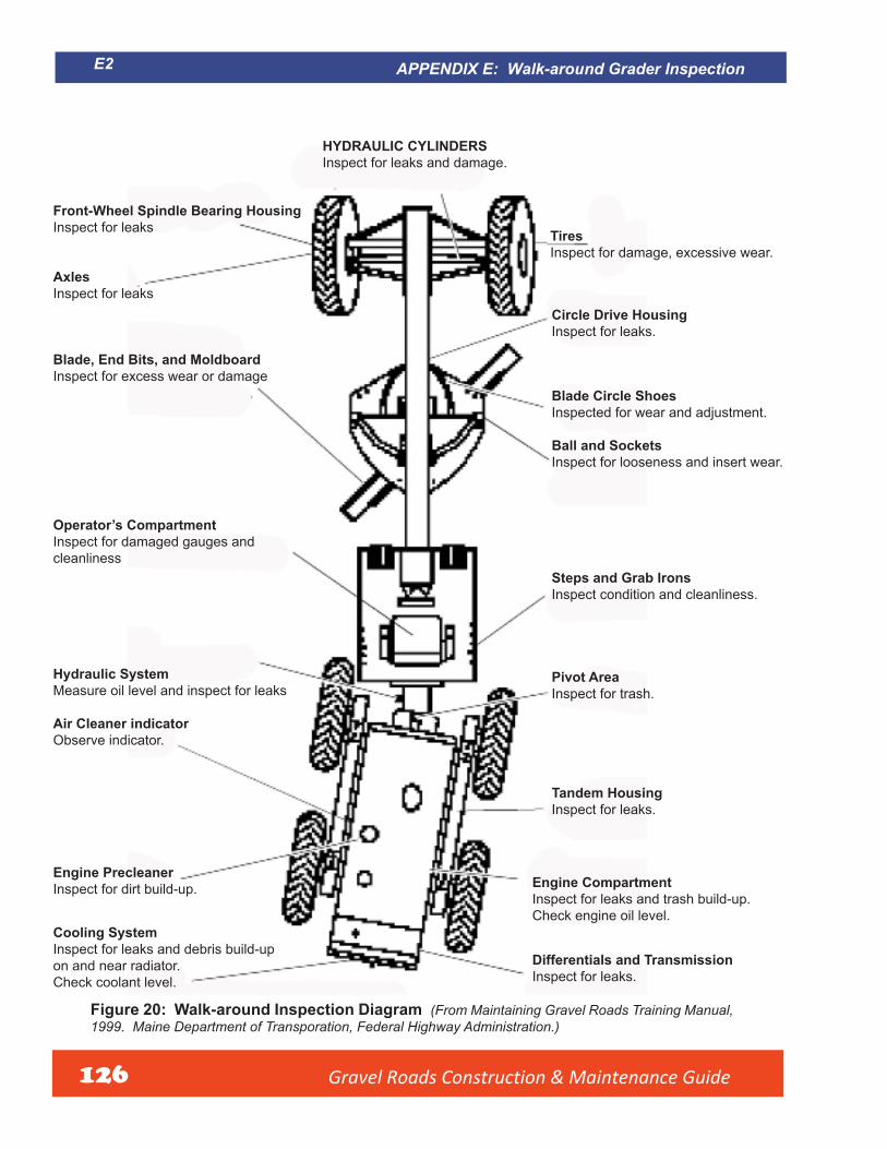
Gravel Roads Construction & Maintenance Guide 126
HYDRAULIC CYLINDERSInspect for leaks and damage.
Front-Wheel Spindle Bearing HousingInspect for leaks Tires
Inspect for damage, excessive wear.
AxlesInspect for leaks
Circle Drive HousingInspect for leaks.
Blade, End Bits, and MoldboardInspect for excess wear or damage
Blade Circle ShoesInspected for wear and adjustment.
Ball and SocketsInspect for looseness and insert wear.
Operator’s CompartmentInspect for damaged gauges and cleanliness
Steps and Grab IronsInspect condition and cleanliness.
Hydraulic System Pivot AreaMeasure oil level and inspect for leaks Inspect for trash.
Air Cleaner indicatorObserve indicator.
Tandem HousingInspect for leaks.
Engine PrecleanerEngine CompartmentInspect for dirt build-up.Inspect for leaks and trash build-up.Check engine oil level.
Cooling SystemInspect for leaks and debris build-up
Differentials and Transmissionon and near radiator.Inspect for leaks.Check coolant level.
Figure 20: Walk-around Inspection Diagram (From Maintaining Gravel Roads Training Manual, 1999. Maine Department of Transporation, Federal Highway Administration.)
APPENDIX E: Walk-around Grader Inspection E2

Figure 21: Motor Grader Preventative Maintenance Check List (From Maintaining Gravel Roads Training Manual, 1999. Maine Department of Transportation, Federal Highway Administration).
APPENDIX E: Walk-around Grader Inspection E3
Gravel Roads Construction & Maintenance Guide 127

Gravel Roads Construction & Maintenance Guide128
Appendix F:
Temporary Traffic ControlFor Work Zones on
Unpaved Roads
SOURCE: Developed under a grant provided by the Federal Highway Administration
thru the Work Zone Safety Consortium
Consortium Member Organizations include:American Association of State Highway and Transportation Officials (AASHTO)
American Road and Transportation Builders Association (ARTBA)Community College Consortium for Health and Safety Training (CCCHST)
Federal Highway Administration (FHWA)International Union of Operating Engineers (IUOE)
National Asphalt Pavement Association (NAPA)National Local Technical Assistance Program Association
Texas A&M Transportation Institute (TTI)

Gravel Roads Construction & Maintenance Guide 129
Guidance Temporary Traff c Control For Work Zones on Unpaved Roads
June 2015
Work Zone Safety Consortium This material is based
upon work supported by the
Federal Highway Administration
Grant Agreement DTFH61-II-H-00029

Gravel Roads Construction & Maintenance Guide 130
PrefaceAccording to the U.S. Department of Transportation, Federal Highway Administration (FHWA), there were 1.4 million miles of unpaved roads in the United States in 2012. Unpaved roads account for about 35 percent of the more than 4 million miles of roads that make up our nation’s transportation systems.1 About 1.3 million miles of these unpaved roads are in rural areas, where local jurisdictions have ownership of about 1.2 million miles.
Temporary traffic control (TTC) is required any time work is performed within the right-of-way of an unpaved road, just as for paved roads. As on paved roads, the TTC plans for unpaved roads should be developed by a trained individual. All TTC plans must comply with local regulations and ordinances and should take into account recommended practices from the national Manual on Uniform Traffic Control Devices (MUTCD).2 A TTC plan should be developed for all work operations conducted on all roadways open to public travel.
ObjectivesThe purpose of this guidance document is to assist agencies responsible for maintenance and construction on unpaved roadways in identifying appropriate TTC for these activities. Typical maintenance activities include grading and pulling debris from ditches, while typical construction activities include resurfacing and reconstruction.
Users of this document will:
• gain an understanding of the ACTIVITY AREA of a TTC zone on an unpaved road,• review the need to warn the traveling population of work zone operations on an unpaved road, and• review safety devices used on equipment when working on an unpaved road.
This document is organized into the following sections:
• Temporary Traffic Control (TTC) Concepts for Unpaved Road• Types of Work Zone Activities on Unpaved Roads• TTC Plans
1 Federal Highway Administration’s Office of Highway policy Information, highway Statistics- 2012 report, “Miles by Type of Surface and Ownership” (http://www.fhwa.dot.gov/policyinformation/statistics/2012/hm12.cfm).
2 Refer to http://www.workzonesafety.org for a copy of this document.
© 2015 American Road and Transportation Builders Association, Washington, DCAll rights reserved. This material is based upon work supported by the Federal Highway Administration under Grant Agreement No. DTFH61-II-H-00029. Any opinions, findings and conclusions or recommendations expressed in this
publication are those of the author(s) and do not necessarily reflect the view of the Federal Highway Administration. This publication does not constitute a national standard, specification, or regulation. No statement made in this booklet should be construed to convey
an impression that any member of the consortium, its affiliates, or employees have assumed any part of the employe ’s exclusive legal responsibility for providing a “safe and healthful workplace” as mandated by the Occupational Safety and Health Act. Nor does
mention of trade names, commercial products, or organizations imply endorsement by the U.S. Government.

Gravel Roads Construction & Maintenance Guide 131
Temporary Traffic Control for Work Zones on Unpaved Roads
IntroductionUnpaved roads typically serve fewer than 3,000 vehicles per day and are used by a wide range of vehicles (automobiles, farm equipment, large trucks, etc.) at high speeds (55 mph or more) depending on the location and characteristics of the roadway.1 Below are descriptions of some features.
• Unpaved roads can be relatively narrow, some lessthan 12 feet in total width. Examples of such roadsinclude those owned by the U.S. Forest Service (FS),the U.S. Bureau of Land Management (BLM), and theU.S. Bureau of Indian Affairs (BIA).
• Traveling over unpaved surfaces (such as gravel or natural surfaces) can generate dust, resulting in reducedvisibility and other temporary work hazards.
• Washboards, potholes, loose material, and inconsistent grades on unpaved road surfaces may affectdrivability and vehicle control.
• Maintenance occurs fairly frequently on unpaved roads, at least twice a year and as often as once a day onmore heavily traveled unpaved roadways.
• Stopping distances are much longer on gravel and natural surfaces than on paved surfaces.
• Most unpaved roads follow the natural grade of the terrain. This may include a number of horizontal andvertical curves that limit the sight distance of approaching motorists.
• Due to the nature of the low-volume unpaved road, the traveling public does not expect to encounter othervehicles.
Maintenance personnel, utility workers, and other staff working in the right-of-way must consider all these characteristics when designing and deploying temporary traffic control (TTC) on unpaved roads
Example unpaved road owned by the U.S. Forest Service(Source: Unpaved Roads Less Traveled Blog).
Responsibility for the design, placement, operation, and uniformity of traffic control devices (TCDs) on unpaved roadways rests with the public agency or official having jurisdiction, or, in the case of private roads open to the public, with the private owner or private official having jurisdiction. Unpaved road owners are primarily local agencies, as well as the Forest Service, the Bureau of Land Management, and the Bureau of Indian Affairs. Other agencies such as State DOTs and private organizations own a much smaller portion of the 1.4 million miles of unpaved roads in the U.S.
TCD on unpaved road (Source: Jo MicheleSheridan).
Temporary Traffic Control (TTC) Concepts for Unpaved RoadsA TTC is required any time work is performed within the right-of-way of an unpaved road, just as for paved roads. The national Manual on Uniform Traffic Control Devices (MUTCD)2 defines the primary function of TTC as “to provide for a reasonably safe and effective movement of road users through or around TTC zones while reasonably protecting road users, workers, responders to traffic incidents and equipment.” The MUTCD includes national TTC requirements for work zone operations on unpaved roads. Signs, channelizing devices, and work vehicle lights can all be used to provide TTC on these roadways. The choice, number, and location of these devices vary by the type of work performed, its duration, and the location of the work within the roadway right-of-way.
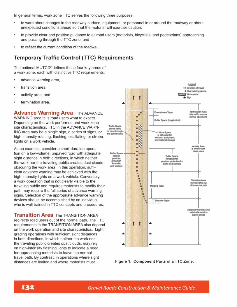
Gravel Roads Construction & Maintenance Guide
In general terms, work zone TTC serves the following three purposes:
• to warn about changes in the roadway surface, equipment, or personnel in or around the roadway or aboutunexpected conditions ahead so that the motorist will exercise caution;
• to provide clear and positive guidance to all road users (motorists, bicyclists, and pedestrians) approachingand passing through the TTC zone; and
• to reflect the current condition of the roadwa .
Temporary Traffic Control (TTC) Requirements
The national MUTCD2 defines these four key areas of a work zone, each with distinctive TTC requirements:
• advance warning area,
• transition area,
• activity area, and
• termination area.
Advance Warning Area The ADVANCEWARNING area tells road users what to expect. Depending on the work performed and work zone site characteristics, TTC in the ADVANCE WARN-ING area may be a single sign, a series of signs, or high-intensity rotating, flashing, oscillating, or strobelights on a work vehicle.
As an example, consider a short-duration opera- tion on a low-volume, unpaved road with adequate sight distance in both directions, in which neither the work nor the traveling public creates dust clouds obscuring the work area. In this operation, suffi-cient advance warning may be achieved with the high-intensity lights on a work vehicle. Conversely, a work operation that is not clearly visible to the traveling public and requires motorists to modify their path may require the full series of advance warning signs. Selection of the appropriate advance warning devices should be accomplished by an individual who is well trained in TTC concepts and procedures.
Transition Area The TRANSITION AREAredirects road users out of the normal path. The TTC requirements in the TRANSITION AREA also depend on the work operation and site characteristics. Light grading operations with sufficient sight distancesin both directions, in which neither the work nor the traveling public creates dust clouds, may rely on high-intensity flashing lights to indicate a needfor approaching motorists to leave the normal travel path. By contrast, in operations where sight distances are limited and where motorists must Figure 1. Component Parts of a TTC Zone.
132

Gravel Roads Construction & Maintenance Guide 133
leave the normal travel path for significant distances, a full series of channelizing devices may be needed to delineate where motorists must leave the lane. Typically, these types of operations will also require flaggers or other means of alternating one-way lanes around the work area. This TTC may need to be installed a significant distance from the workers and equipment. Further, when flaggers are used, they should be properly trained and equipped with a stop-slow paddle.3
Activity Area The ACTIVITY AREA is where the work activity takes place. As with paved roadways,unpaved roadways may require a number of spot maintenance activities including drainage repair and replacement, approach grading, and sign repair and replacement. For these activities, the TTC and the Traffic Control Plan (TCP) on paved and unpaved roads are interchangeable.
An activity unique to unpaved roads is the process of reshaping the road surface. This is accomplished using a motor grader/ maintainer to cut the gravel surface and remove material from the surface, place the material into a berm or windrow, and then spread the material across the full width of the unpaved road. This process is described in the Gravel Roads, Maintenance and Design Manual.4 Most agencies will rework sections of roadway one to two miles long, leaving the berm/ windrow of gravel to be picked up with each pass of the grader. In the Temporary Traffic Control Zone Layout manual of the Minnesota DOT,5 Miscellaneous Layout 6K-72 provides a discussion of the safety equipment needed for the motor graders but does not describe how the berms or windrows can cause a hazard to the motoring public. This hazard potential is discussed on page 6 of this document.
Termination Area The TERMINATION AREA informs the traveling public of the end of the work zone,where motorists return to the normal driving path. As most unpaved roads are two-lane, two-way, and low-volume, the TERMINATION AREA is set up only occasionally as needed for local conditions.
In summary, TTC is required any time work is performed within the right-of-way of an unpaved road, just as for paved roads. Such work includes typical road maintenance activities, but also extends to utility work and driveway and drainage work. The national MUTCD provides examples of TTC typical applications for various types of work situations, such as:
• work beyond the edge of the shoulder,
• work on the shoulder or edge of the road, and
• work in the travel lanes.
On low-volume unpaved roads, high-intensity flashing lights on work equipment and vehicles may be sufficientwhen work- ing beyond or on the edge or shoulder of the road.
As on paved roads, TTC plans for unpaved roads should be developed by a trained individual. All TTC plans must comply with local regulations and ordinances and should take into account recommended practices from the national MUTCD.
Types of Work Zone Activities on Unpaved RoadsThe following work zone activities are commonly performed on unpaved roads:
Grading Grading involves the reshaping of the travelingsurface through removal of all potholes and/or washboards and the re-establishment of the crown of the unpaved road. Grading is performed by a motor grader that cuts the surface of the unpaved road to the bottom of the potholes and/or washboards and then spreads the material across the surface of the roadway.
Pulling Ditches or shoulders due to the nature of anunpaved road, the surface material will migrate off of the road surface and collect in roadside ditches or on the shoulders.
Typical washboard damage on an unpaved road (Source: Jo Michele Sheridan).

Gravel Roads Construction & Maintenance Guide 134
To assist with drainage and to recover the lost material, ditches or shoulders are pulled, which means that road surface material is removed and deposited back onto the roadway.
Resurfacing As vehicles travel the unpaved road, the surface material loses the binder holding it together,requiring replacement of the material. Surface material is hauled onto the roadway, and the roadway is then graded.
Reconstruction An agency may need to increase the amount of ballast under the unpaved roadway toimprove load carrying ability, drainage, or snow removal. This is accomplished by hauling ballast material onto the surface of the roadway, grading the material, and then placing new surface material on top of the ballast.
With each of these work zone activities, temporary traffic control should be planned with consideration of the traveling public and how these activities will impact the safety of both the public and the employees. The following components should be considered.
Components of Unpaved Roadway Work Zone OperationsWhen developing a temporary traffic control plan, the organization should consider the design speed, the traffic volume, the roadway geometrics, and the type of work. With unpaved roads, two additional concerns should be considered.
Location of Berm or Windrow For maintenance andconstruction activities such as reshaping the road surface, it is important to recognize that the berm can create a challenge for the road user. Even a small traversable berm (less than 6 inches across) can affect the traveling public. As the berm size increases, the effect of the berm increases. Therefore, the ACTIVITY AREA for this type of work is located between the beginning and the end of the berm, which may be one to two miles long. The entire berm must be considered a part of the ACTIVITY AREA even if the equipment and crew are located some distance upstream or downstream from the berm.
grader working the unpaved road, a motorist will usually yield the right away to the equipment working in the travel lane. Some State statutes specifically allow the operation of equipment against the flow of traffic when performing road maintenance operations. However, these statutes do not negate the need to warn the traveling public.
An additional concern expressed by equipment operators is dust generated by the grading operation. When the motor grader cuts the surface of the roadway, it exposes the binder in the material to wind or tire action, which makes the roadway very dusty. Such dusty conditions can increase the hazard, not only for the traveling public but also for the operator. In dusty conditions, advance warning is even more crucial. If dust cannot be controlled with moisture, suspend operations.
Flow of Traffic The primary equipment used on an unpaved The entire berm must be considered in developing
road is the motor grader or maintainer. This type of large equip- and deploying TTC. (Source: Equipment World).ment requires a skilled operator and may need to work against the flow of traffic to prevent stretching the material. (Stretching reduces the depth of the material on the roadway and shortens its service life.) Motorists do not expect equipment to be traveling toward them on their side of the roadway. This operation can trap the motorist between the shoulder of the road and the material berm. In the case of a small berm, the motorist can safely cross it. In cases where the berm is larger, the ability of a motorist to cross the berm will be problematic. In areas with adequate sight distance where the motorist can see the motor
Dust poses a hazard for workers and motorists.(Source: Soil Stabilization of Oklahoma).

Gravel Roads Construction & Maintenance Guide 135
Temporary Traffic Control (TTC) Applications on Unpaved Roads Following are three example set ups that demonstrate how MUTCD2 TTC applications can be tailored to meet the specific needs of unpaved roadways. The examples are light grading, surface reshaping, and reconstruction using a detour. The examples all involve sufficient sight distances. On roads with horizontal and/or vertical curves orother sight distance challenges, additional advance warning will likely be required.
Light Grading Light grading generates a berm thatis small enough to be traversable and motorists can see sufficiently ahead to pass safely by the ACTIVITY AREA. Minor grading operations typically involve a single motor grader working with traffic to correctminor issues within the roadway where the berm is approximately 6 inches or less in height. The small berm presents a lower risk of causing the motorist to lose control.
A small berm presents lower risk to the motorist. (Source: Bruce Drewes, 3T Group LLC).
Notes:1. Grading operations should be scheduled and
completed during daylight hours and suspendedduring poor weather or visibility conditions.
2. When grading, using moisture will preventsegregating the material and creating additional dustthat reduces the visibility of the operation.
3. The ROAD WORK AHEAD signs should be installedat the approach of each crossroad or street but nomore than 3 miles from the maintenance operation.
4. When performing light grading (with a berm less than6 inches) the ROAD WORK AHEAD sign may beomitted if there is adequate decision sight distanceso that the equipment can be seen by the motoristapproaching the equipment from either direction. Allwarning and rotating lights should be operating.
5. Motor grader should be equipped with flashing orrotating light in addition to the vehicle’s hazard lights.Flashing or rotating lights should be visible 360degrees around the motor grader when viewed from adistance of 600 feet. Motor grader should be equippedwith a SLOW MOVING VEHICLE sign. The motorgrader blade ends may be equipped with orange flagsto provide additional warning and visibility to passingvehicles.
Figure 2. TTC application for light graging.
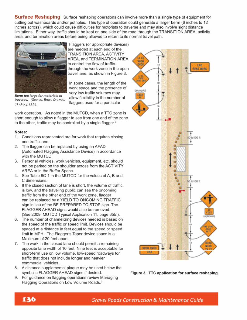
Gravel Roads Construction & Maintenance Guide 136
Surface Reshaping Surface reshaping operations can involve more than a single type of equipment forcutting out washboards and/or potholes. This type of operation could generate a larger berm (6 inches to 12 inches across), which could cause difficulties for motorists to traverse and may also involve sight distance limitations. Either way, traffic should be kept on one side of the road through the TRANSITION AREA, activity area, and termination areas before being allowed to return to its normal travel path.
Flaggers (or appropriate devices) are needed at each end of the TRANSITION AREA, ACTIVITY AREA, and TERMINATION AREA to control the flow of traffic through the work zone in the open travel lane, as shown in Figure 3.
In some cases, the length of the work space and the presence of very low traffic volumes may allow flexibility in the number of flaggers used for a particular
Berm too large for motorists to traverse. (Source: Bruce Drewes, 3T Group LLC).
work operation. As noted in the MUTCD, when a TTC zone is short enough to allow a flagger to see from one end of the zone to the other, traffic may be controlled by a single flagger.3
Notes:1. Conditions represented are for work that requires closing
one traffic lane.2. The flagger can be replaced by using an AFAD
(Automated Flagging Assistance Device) in accordancewith the MUTCD.
3. Personal vehicles, work vehicles, equipment, etc. shouldnot be parked on the shoulder across from the ACTIVITYAREA or in the Buffer Space.
4. See Table 6C-1 in the MUTCD for the values of A, B andC dimensions.
5. If the closed section of lane is short, the volume of trafficis low, and the traveling public can see the oncomingtraffic from the other end of the work zone, flaggercan be replaced by a YIELD TO ONCOMING TRAFFICsign in lieu of the BE PREPARED TO STOP sign. TheFLAGGER AHEAD signs would also be removed.(See 2009 MUTCD Typical Application 11, page 655.).
6. The number of channelizing devices needed is based onthe speed of the traffic or speed limit. Devices should bespaced at a distance in feet equal to the speed or speedlimit in MPH. The Flagger’s Taper device space is aMaximum of 20 feet apart.
7. The work in the closed lane should permit a remainingopposite lane width of 10 feet. Nine feet is acceptable forshort-term use on low volume, low-speed roadways fortraffic that does not include longer and heaviercommercial vehicles.
8. A distance supplemental plaque may be used below thesymbolic FLAGGER AHEAD signs if desired.
9. For guidance on flagging operations review ManagingFlagging Operations on Low Volume Roads.3
Figure 3. TTC application for surface reshaping.

Gravel Roads Construction & Maintenance Guide 137
Reconstruction Using a Detour When the reconstruction and resulting berm are significant, the workspace takes all or most of the road surface, leaving no room for traffic to negotiate past the work activities.
An agency may need to reconstruct the unpaved roadway by correcting the drainage and/or adding surface materials. With this type of work, additional equipment may be used and a large amount of material may create a large berm (12 inches or more across). This will present significant hazards for the traveling public. To improve safety for motorists and workers, a detour may be the best TTC. Not all road users will be familiar with the local road system and some may be confused by the road closure, so signing should be used to assist users negotiating the detour.
Reconstruction work space. (Source: Greg Vavra, SDLTAP).
Figure 4. TTC application for reconstruction using a detour.
Notes:1. Not all local agencies use route
makers for their system. MUTCDSection 6F.59 states “A StreetName sign should be placedabove, or the street name shouldbe incorporated into, a DETOUR(M4-9) sign to indicate the nameof the street being detoured.”
2. With an increase in traffic at theintersections where the detourbegins and ends, a review of theusage of the STOP and YIELDsigns should be completed.
3. Flashing warning lights and/orflags may be used to call attentionto advance warning signs.
4. Flashing warning lights may beused on the Type 3 Barricades,which should be installed at thepoint where the road is closed.
5. For more complex TTC signingsituations, technical assistancecan be obtained from the localLTAP/TTAP or State DOT.Rep
laced
- See
Erra
ta

Gravel Roads Construction & Maintenance Guide 138
Temporary Traffic Control PlansTo assist and protect the transportation agencies/organizations, as well as the traveling public, Section 6C.01 of the national MUTCD2 provides guidance on the development of Temporary Traffic Control Plans.
Key elements:
• A traffic control plan should be developed for all operations conducted on all roadways open to public travel. Aplan may be a simple drawing of a typical traffic control plan that addresses the safety of all parties travelingin, around, or through the work area.
• Persons purchasing, designing, setting up, and maintaining traffic control elements should be trained for thejob decisions they will make.
• The public’s primary concern is to travel from point A to point B. Motorists do not expect delays due toconstruction or maintenance activities. Advance warning is a primary tool to warn the public of theseactivities. Without advance warning, the motorist may be surprised or confused by the construction ormaintenance work.
Unpaved roads are usually low-volume roads, which may lead to motorists traveling at higher speeds. The setup of the signs in the ADVANCE WARNING area is the primary – and sometimes only – warning before the motorist enters the work space. The ADVANCE WARNING area should inform motorists of the hazards they will encounter.
ConclusionThis guidance document is intended to assist agencies and organizations that own or work on our nation’s unpaved road system. The document has provided information of the following key points:
• The primary maintenance performed on unpaved roads is grading the surface to improve ride-ability and drainage and to remove defects. Other mainte-nance includes pulling shoulders/ditches, resurfac-ing/regraveling, and stabilization of the surface.
• This document encourages agencies that maintain unpaved roads to review policies, standards, and traffic control plans to ensure these meet the needs of the organization and ensure the safety of the driving public.
• A motor grader performing a light grading operation is usually a mobile operation that moves continuously and may also meet the definition of a short-term work operation provided in the national MUTCD; i.e., more than one hour and less than one daylight period.
• This document presents three temporary traffic control plans identifying temporary traffic controldevices that may be needed to provide positive guidance to the traveling public.
• The personnel developing temporary traffic control should be trained for the job decisions they will make.
• All agencies and organizations should have specific temporary traffic control plans beforeworking on or in roadways. The TTC plan should consider the safety of all road users and work zoneemployees.
Grading is the primary maintenance performed on un-paved roads (Source: Envirotac).

Gravel Roads Construction & Maintenance Guide 139
References1. Federal Highway Administration’s Office of Highway Policy Information, Highway Statistics-2012 report, “Miles by Type of
Surface and Ownership” (http://www.fhwa.dot.gov/policyinformation/statistics/2012/hm12.cfm).
2. Manual on Uniform Traffic Control Devices. Federal Highway Administration (FHWA), U.S. Department of Transportation,Washington, DC. 2009. http://mutcd.fhwa.dot.gov
3. Guidance: Managing Flagging Operations on Low-Volume Roads. The Work Zone Safety Consortium and the FederalHighway Administration (FHWA), U.S. Department of Transportation, Washington, DC. 2015. www.workzonesafety.org/research/record/47559
4. Gravel Roads Maintenance and Design Manual. South Dakota Local Technical Assistance Program (LTAP) and theFederal Highway Administration (FHWA), U.S. Department of Transportation, Washington, DC. Ken Skorseth and A.A.Selim, 2000. http://www.mnltap.umn.edu/publications/videos/gravelroadmaintenance/documents/manual.pdf
5. Minnesota Department of Transportation, Temporary Traffic Control Zone Layouts http://www.dot.state.mn.us/trafficengpubl/fieldmanual/index.htm

Gravel Roads Construction & Maintenance Guide 140
Notes

Gravel Roads Construction & Maintenance Guide 141
This material is based upon work supported
by the Federal Highway Administration under
Grant Agreement No. DTFH61-II-H-00029.
Any opinions, findings and conclusions o
recommendations expressed in the
publication are those of the author(s) and
do not necessarily reflect the view of th
Federal Highway Administration. This
publication does not constitute a national
standard, specification or regulation
Work Zone Safety Consortium(202) 289-4434Together, we represent all segments of the rodway construction industry.
AMERICAN ROAD ANDTRANSPORTATION BUILDERSASSOCIATION (ARTBA)www.artba.org(202) 289-4434
INTERNATIONAL UNIONOF OPERATING ENGINEERS(IUOE)www.iuoe.org
COMMUNITY COLLEGECONSORTIUM FOR HEALTHAND SAFETY TRAINING(CCCHST)http://www.mhtri.org/ccchst/ccchst_index.html
NATIONAL ASPHALT PAVEMENT ASSOCIATION (NAPA)www.asphaltpavement.org
NATIONAL LOCALTECHNICAL ASSISTANCE PROGRAM ASSOCIATIONhttp://www.nltapa.org
FEDERAL HIGHWAYADMINISTRATIONU.S. Department of Transportationwww.fhwa.dot.gov
AMERICAN ASSOCIATIONOF STATE HIGHWAY ANDTRANSPORTATION OFFICIALS(AASHTO)www.transporation.org
TEXAS A&MTRANSPORTATION INSTITUTE (TTI)www.tti.tamu.edu
FOF COMMUNICATIONSWashington, D.C.www.fofcom.com

FHWA Publication No.: FHWA-OTS- 15-0002