gravimetric blenders gxb series 4 instruction...
TRANSCRIPT

GRAVIMETRIC BLENDERS
GXB SERIES 4 INSTRUCTION MANUAL
M-Tek Division of Mould-Tek Industries, Inc., 77 Nantucket Boulevard, Toronto, Ontario. Canada M1P 2N5 Ph. 416-285-5400 Fax 416-285-5432 www.mould-tek.com e-mail: [email protected]
INSTRUCTIONS FOR: INSTALLATION OPERATION TROUBLE SHOOTING MAINTENANCE SPECIFICATIONS ELECTRICAL DIAGRAMS
Series 20
Series 50
Series 100
Series 200
Series 400
Series 600

It is recommended you record the model, serial number(s) and date received of the equipment in the area provided below. This information is required by our service department to help you efficiently and effectively. Please retain this instructional manual, engineering drawings and parts list in a safe place for quick and easy reference of your equipment.
MODEL NUMBER(S)
SOFTWARE VERSION
SERIAL NUMBER(S) DATE RECEIVED
POWER SUPPLY 120 VOLTS AC 240 VOLTS AC Your safety is our concern! Exercise good judgement when operating electrically powered equipment. Never open the control cabinet or disassemble any of the components without first shutting off the main power. Use the GXB Series 4 Blender for the intended purpose only, metering and mixing dry free flowing materials such as pellets and granules.
GAIN SETTINGS
MODEL GXB24 – 110 MODEL GXB56 – 10 MODEL GXB106 – 100 MODEL GXB208 – 100 MODEL GXB408 – 10 MODEL GXB608 – 10 Disclaimer: Mould-Tek Industries Inc. shall not be liable for errors contained in this GXB Series 4 Instruction Manual or for incidental, consequential damages in connection with the furnishing, performance or use of this information. Mould-Tek Ind. Inc. will not make warranties of any kind with regard to this information, including, but not limited to the implied warranties of merchantability and fitness for a particular purpose.
Effective: February 21st, 2006
2

3
TABLE of CONTENTS
Safety warnings and features .........................................................................4 Disclaimers ....................................................................................................5 Installation......................................................................................................6
SECTION A Standard Operating Sequence ........................................................................7 Power On .......................................................................................................8 Security Codes ...............................................................................................8 Quick Start Operation ....................................................................................9
o Start Sequence, Step1.........................................................................9 o Preset Batches ....................................................................................10 o Revise Formula Sequence, Step 2......................................................10
Materials Hopper Identification.....................................................................12 Formula Build ................................................................................................13
o Build Sequence ..................................................................................14 o Starting your Blender.........................................................................15 o Viewing Diagnostic Screen................................................................16
Materials Dispensing Sequence .....................................................................17 Materials Layering .........................................................................................17 Regrind Materials, “SMART” Mode.............................................................19
o Set-Up ................................................................................................21 SECTION B
Parameters, Set-Up ........................................................................................22 o Date/Time ..........................................................................................22 o Utility .................................................................................................22 o Batch Time Alarm, item #1 ...............................................................22 o Material Feed Alarm, item #2............................................................22 o Mixer Level, item #4..........................................................................23 o Pinch and Auger delay, item #5.........................................................23 o Alarm, activate and deactivate, item #6.............................................23 o Scale Set-up .......................................................................................23 o Language............................................................................................23
Manual Operation ..........................................................................................24 Reports ...........................................................................................................25
o Cycle ..................................................................................................25 o Diagnostic ..........................................................................................27 o Batch ..................................................................................................29 o Formula ..............................................................................................30 o Inventory ............................................................................................31
Mixer, Set-Up ................................................................................................32 Trouble shooting Guide .................................................................................33 Maintenance...................................................................................................34 Specifications.................................................................................................35 Electrical diagrams.........................................................................................41
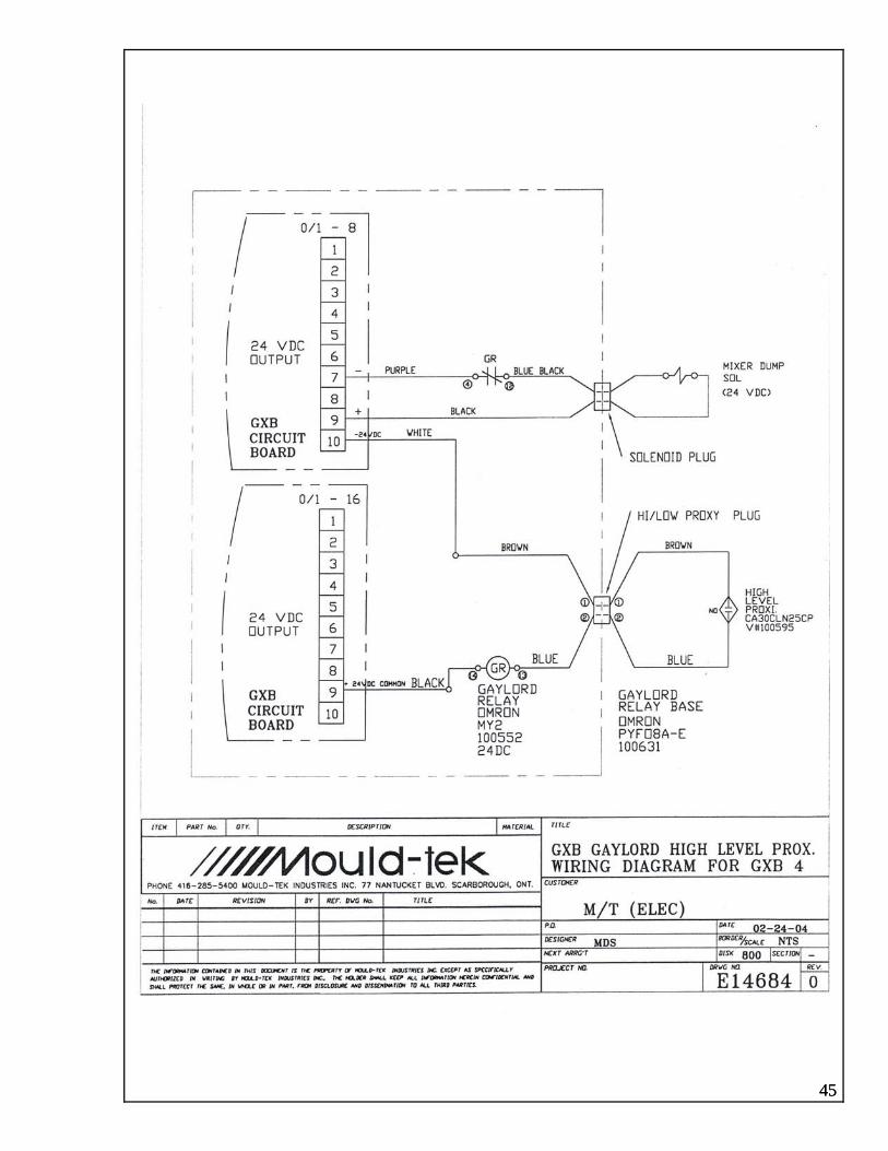
o Control panel components layout # 11775 Rev2...............................41 o Control terminal connections # 13592...............................................42 o Solenoid Pin connections # 13593.....................................................43 o External Alarm # 12971.....................................................................44 o Gaylord fill level switch # E14684 ....................................................45

4
SAFETY WARNINGS
PINCH VALVES (each hopper is fitted with a Pinch Valve for material dispensing) Do not place hands or fingers between pinch bars. Do not clear obstructions with fingers. Disconnect air supply before servicing Pinch Valves.
MIXER DISCHARGE (when fitted with Posi-Valve)
Do Not place hands or fingers in mixer discharge outlet. Do not clear obstructions with fingers. Disconnect air supply before servicing mixer discharge Posi-Valve.
MIXER BLADE (all blades are driven by a high torque electric motor)
Do not place hands into mixing chamber when in operation. Do not clear obstructions with hands or any other object when in operation. Replace damaged mixer blade immediately. Turn power off before servicing mixing chamber.
SAFETY FEATURES SAFETY GUARDS (each blender is supplied with safety guards in hazard areas)
Do not operate blender with safety guards removed. Replace all guards immediately after servicing blender. Do not replace guards with inferior materials use original manufacture components only.
SAFETY SWITCHES (each blender is supplied with safety interlocks switch) Do not remove safety interlock switch. Do not operate blender without safety interlock switch. Do not short circuit safety interlock switch. Replace defective safety interlock switch immediately.
Note: Failure to adhere to the above can result in bodily harm and equipment damage.

5
DISCLAIMERS DEFECTIVE PRODUCT PRODUCTION Production conditions and materials will vary widely from customer to customer. We cannot anticipate all of the processing conditions and/or requirements and confirm that the equipment will perform perfectly in all conditions. It is the customer’s responsibility to review and confirm the equipment performance based on the overall manufacturing process is to their satisfaction. We cannot be held responsible for losses due to incorrect blending of product, equipment malfunction or incorrect design for your requirements and/or consequential losses due to equipment not blending to requirements. Our responsibility is to repair, replace, correct or accept return of the equipment for refund if the equipment does not perform as designed or we have inadvertently misrepresented the equipment to the application. INSTRUCTION MANUAL ACCURACY Every effort is made to maintain this manual as current and correct as possible. Product technology and changes occur prior to reprinting. Modifications made to the operation design of the blender or to the software will not be reflected in the manual for at least 6 months after implementation. We reserve the right to make changes without notice and do not guarantee the manual to be accurate in its entirety. Should you have any questions in regard to information provided in this instruction manual or identify errors, we will appreciate you notifying us so that we may make the applicable corrections. Updated manuals and/or applicable appendix(s) will be gladly provided.

INSTALLATION
1. Place blender in an area where the floor is level and free of obstacles, which may cause damage to the unit.
2. When mounting directly onto the machine throat, utilize a sturdy adaptor, which is capable
of proper support. For design recommendation consult your supplier or the manufacturer.
3. Carefully unpack the control panel and mount onto the blender in the area provided. 4. Connect to the applicable power supply, 110 volt, single phase, 50/60 Hz or 240 volt, single
phase, 50/60 Hz, with 15amp. circuit breaker protection. To prevent any inconsistency of power supply due to fluctuations we recommend a properly grounded separate supply. Voltage fluctuations will result in deficient operation of the blender.
5. Remove all items, which are identified with tag(s). “REMOVE, FOR SHIPPING ONLY.” 6. Connect compressed air supply to the pressure regulator provided. Maximum operating
pressure is 50 – 60 P.S.I. Note: When air is connected and the pressure is set all Pinch Valves will close immediately.
7. Mount minor ingredient hoppers onto minor Pinch Valve feeder housings provided. Check
connections of the compressed air lines. Red airline connects to the rear and the white connects to the front (shaft end) on each air cylinder of each Pinch Valve.
8. Mount applicable vacuum loaders onto material hoppers and connect all required electrics
and compressed air.
9. Your GXB Series 4 Gravimetric Blender is now ready for start-up. Refer to operation procedures.
NOTE: Your unit has been factory tested and approved. The Mould-Tek GXB Series 4 blender features multi-tasking ability to access the following parameters while the blender is in full operation: Formulas; building, revising and viewing. Utility parameters; batch time & material feed time values, regrind set-up, mixer level, pinch
delay and alarms activate & deactivate. Mixer; time value, continuous and timed modes. Reports; viewing and printing. Administration; security codes and access time value.
The following can only be performed when the blender is stopped: Cycle mode; changing operating from one formula to another. Deleting active formula. Scale calibration. Manual operation.
6
Model configuration.

SECTION A STANDARD OPERATING SEQUENCE The Following describes the complete batch cycle sequence of the GXB Series 4 Blender.
7
POWER ON: Refer to page No.11. SELECT FORMULA: Refer to page No.15 and/or 14. START CYCLE: Refer to page No.15. DISPENSE MATERIALS, 1 THRU 8: Each material is dispensed individually. The sequence in which the materials are dispensed is programmable by the operator. Refer to page No.16. SCALE DISCHARGE: All materials are discharged into the mixing chamber. MATERIALS ARE MIXED: Timed Mix Mode; the mixer agitator rotates for the set mix time and stops when this time has elapsed. Continuous Mix Mode; the mixer agitator rotates continuously. Refer to page No.31. MIXER AWAITING DISCHARGE: The blender is in a paused mode awaiting the mixed material to be discharged. When the mixed material is discharged to the level below the mixer sensor the scale discharges the weighed material being held in the scale and the cycle repeats. For the many additional features of the GXB Series 4 Blender, refer to the Table of Contents of this instructional manual.
Power On.
Select Formula
Start Cycle
Dispense material #1
Dispense material #2
Dispense material #3
Dispense material #4
Dispense material #5
Dispense material
#6
Dispense material
#7
Dispense material
#8
Scale Discharge
Materialsare
mixed
Mixer AwaitingDischarge

POWER ON
8
Turn power on at the main switch located on the right side of the control panel. The Start up screen will appear displaying the Model number, Serial number and Software Version as shown below.
After a few seconds has elapsed, the Main Menu screen will be displayed. From the Main Menu operation selections are made. All functions are displayed by individual Touch Button fields and are selected by touching each with your finger. When you have selected a function the Touch Button will Hi-lite confirming your selection. The software automatically controls the screen contrast however; in some conditions manual adjustment will be required. To make the screen darker touch and release the shaded button repeatedly until you are satisfied with the setting. To make the screen brighter repeat the sequence using the un-shaded button . SECURITY CODES Use of the Security codes is optional. The blender does not require security codes to operate. It is recommended when security of data is necessary. Two levels of security is available, Administration and User. The administration
security allows access to view and revise all data and parameters including the user code. The User security allows access to view and revise Reports, Formulas, Mixer and Cycling Parameters. SETTING SECURITY CODES AND ACCESS TIME: 1. From the Main Menu select
Administration, this will display the Administration screen.
2. Select Set User Security Code by touching the numerical button located at the right. A numerical keypad will be displayed.
3. Select the applicable numerical code (each number selected will be displayed in the upper right field) and touch Save. Your code is stored and will be displayed in the field of the User Security Code.
4. Repeat this procedure for Administration Code and Security Time (sec).
Note: The Security Time is the access time allowed, when this time has elapsed you will be required to re-enter your code to continue. However, when any function Touch Button and/or entry of data is performed the security timer resets continuously. Time elapses when none of the afore mentioned is performed. Recommended value is – 30 seconds. Model Changes: This is factory set. Contact the factory for further information.

SECTION A QUICK START OPERATION Your GXB Series 4 Blender is supplied from the factory pre-programmed with one formula identified 1A. This formula will consist of the specified materials arrangement for each particular model purchased. The following is a list of standard materials arrangement based on the number of materials required for blending. Identify the applicable model, materials arrangement and proceed to Quick Start instructions.
Materials Arrangement Number of
Materials Majors
Virgin & Regrind Minors
Additive & Color Applicable Models
2 1 1 GXB 24, 54, 104, 204, 404 & 604 3 2 1 GXB 24, 54, 104, 204, 404 & 604 4 2 2 GXB 24, 54, 104, 204, 404 & 604 5 4 1 GXB 55, 105, 205, 405 & 605 6 4 2 GXB 56, 106, 206, 406 & 606 7 4 3 GXB 207, 407 & 607 8 4 4 GXB 208, 408 & 608
Note: For materials arrangement other than listed above refer to Formula Build section.
The GXB Series 4 control is based on a Menu driven format. The operator has access to all parameters for editing present data or entering new data through the quick response bright-lit touch screen. From the Main Menu operational selections are made. All functions are identified by individual touch button fields and are accessed by touching each with your finger for a second. When touched each will Hi-lite confirming your selection and the required screen will be displayed. As stated above your GXB Series 4 is provided with a pre-programmed formula 1A, the preset value of each major ingredient (virgin and/or regrind) will be greater than 4% and each minor ingredient will be less than 4%, example: Models GXB 24, 54, 104, 204, 404 and 604 are capable of blending a maximum of four materials, two major ingredients @ 48% each and two minor ingredients @ 2% each. This pre-programmed formula is to assist you in getting your blender up and running quickly. Should this formula meet your requirements proceed to Start Sequence Step 1 below, should you need to revise this formula proceed to Revise Formula Step 2.
Start Sequence, Step 1 1. From the Main Menu select Cycle.
2. The Cycle Set-up screen will appear. Formula 1A will be displayed hi-lited, similar as shown. Select Auto/Single. 9

3. The Auto Single screen will appear.
10
4. Select Auto, the blender will begin to
operate and the Monitor screen will appear displaying all running parameters; Materials I.D., preset % of each ingredient, preset unit value, total amount of material processed, total batch unit value, the number of batches processed and the blending rate.
5. Preset Batches: The operator has the option of programming a preset number of total batches required for a specific production run. Select the touch button below the Auto button, a numerical keypad will be displayed, select the number required and touch Enter. The preset number and each completed batch will be displayed on the Monitor screen. When the preset count is completed the blender will stop and the preset number will be highlighted indicating the count is complete. To operate continuously without preset counts enter 0, the blender will operate until the operator stops it.
6. To pause the blender select Pause, the
unit will stop immediately and the Pause field will become hi-lited. To restart again select Pause, the blender will commence operation at the same point of the cycle the Pause was initiated. The hi-lite will be removed from the Pause field.
7. To stop the blender select Stop, the field
will hi-lite and change to display wait. The blender will continue to operate completing the batch cycle.
When the unit has stopped the Wait field which is hi-lited will change to display Stopped and the total number of batches processed.
To restart the blender Return to Main Menu by touching the button. Repeat Steps 1 to 4. Revise Formula Sequence, Step 2 1. From the Main Menu select Formula
Setup.
2. You will be requested to enter your User
security code. At this time your User security code has not been set-up. Touch 0 then Save.

11
. Select the required value by touching the
y
ote, the screens here shows Virgin material ce
. From the Main Menu select Cycle, the Cycle
. In the Formula list scroll down to 1B,
. Touch the Auto button, the blender will
ill
OTE:
3. The Formula Setup screen will appear displaying the factory preset formula 1A similar to screen shown below.
4. Select Revise from this screen.
You will notice that the Formula has been changed from an A designation to B designation. 5. We will now edit the preset % of each
material and designate each material used. Firstly, using the scroll buttons scroll up or down to select which material requires revising. When selected touch the Enter % button, this will display the numerical keypad.
6
appropriate number buttons followed by Save. The new value will be automaticallentered.
Nrevised from 48 to 42%. Continue this sequenfor each material. When each material value is revised touch the Return to Main Menu button . You are now ready to start the blender into operation.
7
Setup screen will appear.
8
touch Auto/Single button, the screen will appear.
9begin to operate and the Monitor screen wappear displaying all running conditions. To Stop or Pause the blender, refer to items 5 and 6 of Quick Start Operation Step 1.
N Calibration of the scale is factory set ior
this
or the many additional features of the GXB s
however, the zero point may require setting prto start-up. The red LED must display 00.00 or 000.00 depending on the model. Should the LEDdisplay –0.00 or –00.00 the scale must be re-zeroed. Refer to the Calibration procedure in manual. FSeries 4 Blender, refer to the Table of Contentof this instructional manual.

MATERIALS HOPPER IDENTIFICATION
The materials hopper identification procedure is required to correctly identify each material stored in its desired hopper. The following instructions demonstrate hoppers identification for Virgin, regrind, Color and Additive materials utilizing the Materials Library of the GXB Series 4. This library consists of a variety of materials, 14 generic names, 5 regrind, 8 colors, 8 additives and 6 unused. The library is to assist the operator when building formulas to correctly identify each material for proper tracking of material usage and batch cycle reports. Note: This procedure is required prior to entering new formulas.
12
Procedure: 1. From Main Menu select Formula Setup.
Enter security code.
2. From Formula Setup select Hopper Setup.
3. Using the up arrow, scroll to #1 position and select the Material touch button.
4. Select the Virgin touch button. Your selection will automatically be assigned to #1, Virgin.
ble. o access each material name, use the left and
libr
5. Repeat for Regrind, Color, Additive and alladditional materials for assignment to hoppers #2 thru #8 where applica
Tright arrows for scrolling through the materials
ary to display screens as shown.

FORMULA BUILD
he GXB Series 4 control includes multiple standard options for building formulas, all easily erformed by the operator. ption A: Colors and Additives added to the virgin material only. ption B: Colors and Additives added to the total batch. cluded in the GXB series 4 is a library identifying a variety of materials consisting of 14 generic
ames, 5 regrind, 8 colors, 8 additives and 6 unused. This library is to assist the operator when building formulas to correctly identify r tracking of material usage and batch cycle reports.
atch is and Additive (without asterisk) or Color* and Additive* (with asterisk)
TpOOInn
each material for prope
The control of when color and additive is added to the virgin material only or to the total bdetermined by using Color respectively.
Materials Library
Virgin Materials Regrinds Colors Additives Unused VIRGIN NYLON Regrind 1 Color 1 Additive 1 Unused 1ABS PET Regrind 2 Color 2 Additive 2 Unused 2ACRYLIC POLYCARBONATE Regrind 3 Color 3 Additive 3 Unused 3HDPE POLYETHYLENE Regrind 4 Color 4 Additive 4 Unused 4HIPS POLYPROPYLENE Regrind* Color* Additive* Unused 5LDPE POLYSTYRENE or* 2 Additive* 2 Unused 6 ColLLDPE PVC Color* 3 Additive* 3 Color* 4 Additive* 4
Depending upon the model the GXB Series 4 is capable ul 8 smaller models can blend a m . A comb of mu an r as ed. The followin ts show s de nd dded to the virg nt onl dep t color* an e* ch.
Opt n A, Char
A1 (4 components) A2 (5 components)
of form ating up to materials, aximum of 4 materials
ination ltiple regrind, color d additive content pe formula is e ily achievg char a variety of formula ; charts A1 thru A4 pict color a additive a
in conte y, charts B1 thru B2 ic d additiv added to a total 5 lb bat
io t 1
Virgin 60% 3 lbs Polystyrene 55% 2.75 lbs Regrind 40% 2 lbs Regrind1 22.5% 1.125 lbs Color 2% 0.06 1.125 lbs lbs Regrind2 22.5%Additive 2% 0.06 lbs Color1 4% 0.11 lbs Additive1 4% 0.11 lbs Total 104% 5.12 lbs Total 108% 5.22 lbs
Option A, Chart 2
A3 (6 compone (5 components) nts) A4Polypropylene 35% 65% 3.25 lbs 1.75 lbs ABS Regrin 0 lbs R 75 lbs d1 20% 1. egrind1 35% 1.Regrind2 % 5 lb bs25 1.2 s Color1 2% 0.065 lR % lbs ve1 egrind3 20 1.0 Additi 4% 0.13 lbsColor1 % ve2 3 0.052 lbs Additi 4% 0.13 lbsA % dditive1 3 0.052 lbs Total 106% 5.10 lb 0% s s Total 11 5.32 lb
13

14
on B, Chart Opti
ts)1 5 com ts)B1 (4 componen B2 ( ponen
Virgin 56 2. ly 5 2.% 8 lbs Po styrene 4 % 25 lbs Regrind1 40 2 g 3 1.% lbs Re rind1 2 .5% 175 lbs Color* 2% 0. g 1. 1 lbs Re rind2 23.5% 175 lbs Additive* 2% 0. lo 0. 1 lbs Co r*1 4% 2 lbs d % 0.2 Ad itive*1 4 lbs Total 10 . ta 10 .0% 5 0 lbs To l 0% 5 0 lbs
Option B, Chart 2
B3 (6 components) B4 (5 components) Polypropylene 35% 1.75 lbs ABS 60% 3 lbs Regrind1 18% 0.9 lbs Regrind1 30% 1.5 lbs Regrind2 23% 1.15 lbs Color*1 2% 0.1 lbs Regrind3 18% 0.9 lbs Additive*1 4% 0.2 lbs Color*1 3% 0.15 lbs Additive*2 4% 0.2 lbs Additive*1 3% 0.15 lbs Total 100% 5.0 lbs Total 100% 5.0 lbs
Formula Build Sequence: The GXB Series 4 allows the operator to build and store formulas with and without revisions. This is beneficial when changes to formulas are required while maintaining its original I.D. Example, a formula which is originally identified as #12345678A can be revised up to four times, B, C, D and E. The original number is retained with alpha designations for each revision. The memory capacity for all formulas is 100, this will vary depending upon the amount of revised and non-revised formulas stored. The maximum characters available for I.D are eight (8). Steps: 1. From the Main Menu select Formula Setup.
Enter security code.
2. Select touch button New.
3. Enter your Formula I.D number.
4. The Edit Revise Formula screen will be displayed.
5. Using the up arrow, scroll to #1 position. Select the Material button.

15
6. Scroll through the materials list using the
Left or Right ar ttons threquired material name. Your selection will automatically be assigned to #1. SeleEnter % button.
elect the
8. Repeat steps 5 through 7 for additional
materials. As each material value is entered the total of the formula’s % is displayed.
When the complete formula is entered select the Return to Main Menu button. Your blender is now ready to operate with the
e you have
deleted. To delete thselectidentifica
Starting your blender:. Scroll through the materials list using the
Left or Right ar ttons threquired material name. Your selection will automatically be assigned to #1. SeleEnter % button.
elect the
8. Repeat steps 5 through 7 for additional
materials. As each material value is entered the total of the formula’s % is displayed.
When the complete formula is entered select the Return to Main Menu button. Your blender is now ready to operate with the
e you have
Note: Formula shown in list with an * (18*A) identifies the last formula ran and cannot be deleted. To delete this formula, in the cycle mode select another formula, this will revise the * identification to the new selection allowing 18A to be deleted.
Starting your blender:
the Main Menu select Cycle. ycle Setup screen will appear. Using
the the formula number ed.
3 to e.
5.
row burow bu , select, select e e
ct the ct the
7. From the numerical keypad s7. From the numerical keypad srequired value, enter by selecting the Save button. Your selection will automatically be assigned to the #1 position material.
required value, enter by selecting the Save button. Your selection will automatically be assigned to the #1 position material.
formula and materials sequencentered. Continue to Starting Your Blender. formula and materials sequencentered. Continue to Starting Your Blender.
1. From2. The C
scroll arrows select enter
. Select Au /Singl
4. The Auto/Single screen will appear.
Select Auto, the blender will begin to operate and the Monitor screen will appear displaying all of the running parameters; Materials I.D., preset % of each ingredient, preset unit value, total batch unit value, the number of batches processed and the blending rate.
Note: Formula shown in list with an * (18*A) identifies the last formula ran and cannot be
is formula, in the cycle mode another formula, this will revise the *
tion to the new selection allowing 18A to be deleted.

VIEWING DIAGNOSTIC SCREEN
The GXB Series 4 Diagnostic data provides the operatogram values. The accuracies of each material dispense s. The information displayed for viewing is: • Material names • Material flow (numerical value) • • • Wi iden terial
revisions to his set-up. Diag
interval cycles, see page #27. To view the diagnostic information follow these steps: From the Main Menu select Reports.
creen w
and forth of
screen.
r with each material weight dispensed in d from batch to batch are best shown in gram
Target weight requested Actual weight dispensed +/- Deviation dispensed
th this information the operator can quickly tify the dispensing condition of each maand perform any applicable The GXB Series 4 can be programmed to provide nostic printed reports for each cycle or
From the Reports select Diagnostics.
The Diagnostics s ill be displayed.
between the Monitor and the Diagnostic the Diagnostic screen and the return
Note, the operator can view each screen b
reens by selecting the Monitor button at the bottomack
scnavigation button at the bottom of the Monitor
16

17
MA ETERIALS DISPENSING SEQUENC
his
e screen numbered 1 thru 8, each representing a dispense u ld the operator will enter the desired material, this determines the sequence each te if the desire is to dispense Virgin 1st, Regrind 2nd, Color 3rd,
a would enter each material appropriately, Virgin in field #1, Regrind in tive in field #4. This can be programmed in any combination of
t
The operator has the ability to program a preferred sequence of each material to be dispensed. Tsequence is performed in the FORMULA BUILD SEQUENCE, see instructions page #14. In this feature a list of 8 fields are presented on thseq ence. In each fiema rial will be dispensed. For example, nd Additive 4th the operator
field #2, Color in field #3 and Addiup o eight materials. Refer to the following three examples.
#1 #2 #3 Dispense MaterialSequence Sequence s Dispense Materials Dispense
Sequence Materials
1 Virgin 1 Regrind1 1st Polypropylenest st
2nd Regrind y e 22nd Pol styren nd Regrind1 3 Color 3rd Regrind2 3 Color1 rd rd
4th Additive 4th Color1 4th Regrind2 5th Unused 5th Additive1 5th Additive1 6th Unused 6th Unused 6th Regrind3 7th Unused 7th Unused 7th Unused 8th Unused 8th Unused 8th Unused
This ability to program a preferred sequence will result in a good quality homogeneous blend.
MATERIALS LAYERING
he operator has the ability to program each material for layer dispensing. This is particularly advantageous hen blending materials of varying bulk densities, resulting in a good homogeneous mix. or instance a required blend consisting of two materials, one @ 32 lb/cu.ft, one @ 44 lb/cu.ft , volume of ch @ 70% and 30% respectively could produce a poor mix when deposited into the mixer. Note: Excessive ixing will not produce a good mix, in this application excessive mixing could result in de-mixing (or aterial separation). ayering of the materials into th uire a shorter mixing time and roduce a homogeneous mix. Se ramming.
2 Materials Layering (4 layers, 2 per material)
TwFeammL e scale then depositing into the mixer, will req
e the following 4 charts for recommended progp
Chart 1
Dispense Sequence Hopper Material #1 @ 32 lb/cu.ft Hopper Material #2 @ 44 lb/cu.ft1st #1 35% 2nd #2 15% 3 #1 35% rd 4th #2 15%
Total 1 70% 2 30%
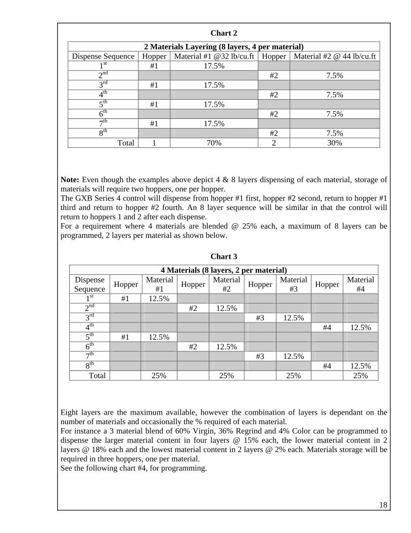
18
2 Materials Layering (8 layers, 4 per material)
Chart 2
Dispense Sequence Hopper Material #1 @32 lb/cu.ft Hopper Material #2 @ 44 lb/cu.ft
1st #1 17.5% 2nd #2 7.5% 3rd #1 17.5% 4th #2 7.5% 5th #1 17.5% 6th #2 7.5% 7th #1 17.5% 8th #2 7.5%
Total 1 70% 2 30% Note: Even t gh th les above pict 4 s dispen g of e torage of materials wil uire t rs, one hoppThe GXB Series 4 control will dispense from ho st, hopp 2 second, return to hopper #1 third and retu to ho th. An 8 lay nce will be similar control will return to hoppers 1 and 2 after each dispense. For a require nt wh terials blend % each, axim ayers can be programmed, yers ial as sh n belo
4 Materials (8 layers, 2 per material)
hou e examp de & 8 layer sin ach material, sl req wo hoppe per er.
pper #1 fir er #rn pper #2 four er seque in that the
me ere 4 ma are ed @ 25 a m um of 8 l 2 la per mater ow w.
Chart 3
Dispense Sequence Hopper Material
#1 Hopper Material Hopper Material #3 Hopper Material
#4 #2 1st #1 12.5% 2nd #2 12.5% 3rd #3 12.5% 4th #4 12.5% 5th #1 12.5% 6th #2 12.5% 7th #3 12.5% 8th #4 12.5% Total 25% 25% 25% 25%
Eight layers are the max ers is dependant on the nu a m For instance a 3 m a f d Cdispense th rger materia ontent in four rs @ 15% each, the lower ma content in 2 layers @ 1 each and the est material c t in 2 layers @ 2% each. Materials storage will be required in three hoppers, one per material. See the foll ing #4, programming
imum available, however the combination of laymber of materials and occasion
aterilly the % required of each 60% Virg % Regrin
aterial. and 4%l b olend
cin, 36 l e
olor can be rogrammed to pe la l ay terial
8% low onten
ow chart for .

19
r 2 a
Chart 4
3 Mate ials (1 @ 4 layers & 2 @ layers e ch) Dispense
quence Virgin Hopper
Materia#1
ind opper
Materia#2
Color Hopper
Material Se
l RegrH
l #3
1st V n 15% irgi 2nd Regrind 18% 3rd V n 15% irgi 4th Regrind 18% 5th Color 2% 6th Vi in 15% rg 7th Color 2% 8 Virgin 15% th Total 60% 36% 4%
In programming this way the virgin material in relation to the regrind is dispensed in a volume similar to each other and the color is dispensed in two layers. The result is a homogeneous mix with
the operator to program the control for ideal blending.
s, see page #11.
minimum mixing time. Note: The number and percentage of layers utilized can lower the blending rate, however the flexibility of the GXB Series 4 control allows Refer to MATERIALS HOPPER IDENTIFICATION instructions to set-up both Materials Dispensing Sequence and Materials Layering feature
REGRIND MATERIALS
“SMA D
quenc Mode Regrind Try When dispensing regrind mat ials as p of th ed fo ula, the GXB series 4 has the ability to recognize when regrind m terials are not available, au atically revise the formula to batch without regrind, allowing the blender to remain in operation. Also included is our standard REGRIND SETUP ture gramming the blender to visit eac regrind material hopper in intervals of 1 thru 10 batch cy es after the initi nition nd revis n of form . When regrind materials are again recognized as bein availabl the G Seri ill rev rt to its riginal formula which includes regrind as part of he formu and con inue to o rate. EXAMP
hart 1, Sequence A; color and additive are added to a 5lb batch. hart 2, Sequence B; color and additive are added to virgin content only of a 5lb batch.
dditive* - 2%
* @ 2% and additive* @ 2%.
RT” MOA ter
E Se e f
er art e requir rma tom
fea for pro re hcl al recog a io ula
g e, XB es 4 w e o t la t pe
LE: CC Sequence A: The required formula is: Virgin - 48%, Regrind1 - 48%, Color* - 2%, A
1. Virgin hopper dispenses 48%. 2. Regrind hopper runs out of material dispensing only 21.6%, the control recognizes that
material is no longer available. 3. The cycle continues dispensing color
20
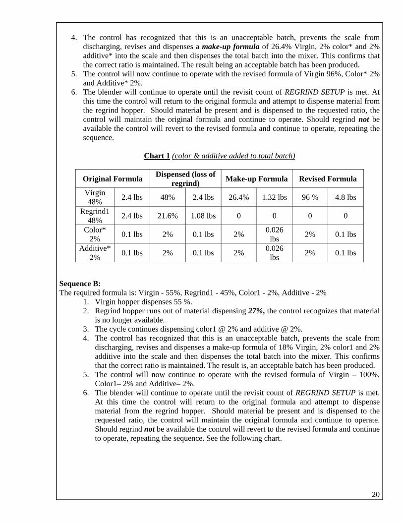
4. The control has recognized that this nacceptable batch, prevents the scale from discharging, revises and dispenses a m ormula of 26.4% Virgin, 2% color* and 2% additive* into the ixer. This confirms that the co is e u n e as uced.
5. The c n ue erat e rev or irg 6%, Color* 2% and Addi * 2%
6. The blender will continue to op visit count of REGRIND SETUP is met. At this time contr turn to the original formula and attem t to dispense material from the regrind hopper. Should ma and is dispensed to the requested ratio, the control will maintain the original formula and continue to operate. Should regrind not be available ised formula and continue to operate, repeating the sequence
is an uake-up f
scale and then dispenses the total batch into the mrrect ratio ontrol will
maintainow contin
d. The resto op
lt being ae with th
acceptablised f
batch hmula of V
been prodin 9
tive . erate until the re
the ol will re pterial be present
the control will revert to the rev.
Chart 1 (color & additive added to total batch)
Original Formula Dispensed (loss of regrind) Make-up Formula Revised Formula
Virgin 2.4 l48% bs 48% 2.4 lbs 26.4% 1.32 lbs 96 % 4.8 lbs
Regrind1 2.4 lbs 21.6% 1.08 lbs 0 0 0 0 48% Color* 0.1 lbs 2% 0.1 lbs 2% 0.026
2%
lbs 2% 0.1 lbs
Additive* 2% 0.1 lbs 2% 0.026
lbs 2% 0.1 lbs 0.1 lbs 2%
Sequence B:
he required formula is: Virgin Additive - 2%
has been produced. vised formula of Virgin – 100%,
TUP is met. this time the control will return to the original formula and attempt to dispense
pensed to the ue to operate.
T - 55%, Regrind1 - 45%, Color1 - 2%, 1. Virgin hopper dispenses 55 %. 2. Regrind hopper runs out of material dispensing 27%, the control recognizes that material
is no longer available. 3. The cycle continues dispensing color1 @ 2% and additive @ 2%. 4. The control has recognized that this is an unacceptable batch, prevents the scale from
discharging, revises and dispenses a make-up formula of 18% Virgin, 2% color1 and 2% additive into the scale and then dispenses the total batch into the mixer. This confirms
at the correct ratio is maintained. The result is, an acceptable batchth5. The control will now continue to operate with the re
Color1– 2% and Additive– 2%. 6. The blender will continue to operate until the revisit count of REGRIND SE
At material from the regrind hopper. Should material be present and is dis
l will maintain the original formula and continrequested ratio, the controShould regrind not be available the control will revert to the revised formula and continue to operate, repeating the sequence. See the following chart.

Chart 2 (color & additive added to virgin)
Original Formula Dispensed (loss of regrind) Make-up Formula Revised Formula
Virgin 55% 2.75 lbs 55% 2.75 lbs 18% 0.9 lbs 100 % 5.0 lbs
Regrind1 45% 2.25 lbs 27% 1.35 lbs 0 0 0 0
Color1 2%
0.055 lbs 2% 0.055
lbs 2% 0.018 lbs 2% 0.1 lbs
Additive 2%
0.055 2% 0.055 2% 0.018 2% 0.1 lbs lbs lbs lbs
ode will au is recognized. hen dispensing multiple regrinds, each a part of a single formula, the SMART mode will function
as desc h r i
“SMART” MODE SET-UP
The SMART mW
tomatically function whenever the loss of regrind
ribed addressing eac egrind material indiv dually.
21
1. Fr ain se am
Enter security code.
2. Fro
3. Fro
uperical keypad will
5 rval num r, 1 thru 0. Th val n r yo is the umber of cycles the blender will batch d re the R d ho check r regri ateria
Sequence as follows, (assuming 3 is the interval number): A: The control has recognized that regrind
B: The control will initiate either Sequence A,
batching preference). red and available for
Should a formula consist of multiple regrind
, identify the remaining two with a generic name such as Nylon and ABS.
om the M Menu lect Par eters.
m the Parameters screen select Utility. page #17 or B, page #18 (dependant on
m the Utility screen select Regrind materials but the “SMART” mode is not required for all, use a material name other than Regrind to identify the materials not applicable. Example, a formula consisting of four regrind materials and two require the “SMART” mode
Set4. The Regrind Setup num
.
appear. . Enter the required inte be
1n
e inter umbe u enter
anfo
turn to nd m
egrinl.
pper to
material is no longer available.
C: All data will be storeporting. NOTE: The “SMART” mode can be used for multiple regrind materials when part of a single formula. Each regrind material will beaddressed individually.

22
SECTION BPARAMETERS, SET-UP
All par etyou contact the factory prior to marevision rec l af e performa yo r. From t Me Pa rs.
Param
any necess
DA
ameters are factory s . We recommend king
s; incornce of
t data wilur blende
fect th
he Main nu select ramete
Enter your security code. eters screen will be displayed.
The following steps will guide you throughary revisions. Your User security
will be required.
TE/TIME Validates all Cycle, Batch and Inventoryreports. Date and Time are recorded on eachprinted report. 1. Select Date/Time. The Date/Time screen
will be displayed.
Upon selection of Year, Month, Date,
2.
Hour and Minute a numerical keypad will be displayed for all data revisions.
AM to PM, select the AM and/or PM button. (The same button
n 24Hr to 12Hr, select the
Hr 2H (T tton be 4H Hr).
UTILITY
3. To change from
toggles betwee4. To change from
AM and PM).
24bu
and/or 1 toggles
r button.tween 2
he samer and 12
eter values fo e
, M ial F Ala egrind
l, Pinc lay, A Del larms ON/OFF. Note: Pinch Delay is applicable to
nd Auger
r Minor Feeders.
through the displayed numerical keypad.
ts the total acceptable time
blender operation, the audible alarm will function and a visual message will be
Consist ofAlarm
Paramater
r Batch Timrm, Reed
“SMART” mode Set-up Leve
(Ref: page 17), Mixer ugerh De ay and A
specific operating software version aDelay is applicable to blenders fitted with Auge
All data for each parameter will be entered
1. Batch Time Alarm – This value (seconds) represen
allowed to elapse when dispensing a complete batch. Should this time elapse and a batch is incomplete, the audible alarm will function and a visual message will be displayed identifying the alarm condition.
2. Material Feed Alarm – This value (seconds) represents the total acceptable time allowed for dispensing material from each hopper. Should this time elapse and material is not completely dispensed, the audible alarm will function and a visual message will be displayed identifying the specific hopper.
3. Regrind Setup - “SMART” mode, this value (numerical) represents how the blender will operate when regrind material is not available. A value of 0 will stop the
23
displayed identifying the alarm condition. A value higher than 0 represents the amou evisiting
nt the revised
) to the original including regrind material. (Ref: page 17)
4. Mixer Level – This value (seconds) d for
af ixer
ma ma
5. milli
pinch as material is dispensed. In case of the auger the delay results in quick short rotations.
6. Alarm – Activates or deactivates the optional Hopper Low Level alarm. (All other alarms audible and visual are not accessible for deactivation). The same button toggles between ON/OFF.
nt of batch cycles required rthe regrind material hopper for material availability. Should regrind be presecontrol will revert back (from the formula/recipe, less regrind
represents the acceptable time allowethe mixer discharge valve remaining open
ter the material flows below the mlevel sensor. A high value maintains less
terial in the mixer, a low valueintains more material.
Pinch and Auger Delay – This value (seconds) represents a delay between each
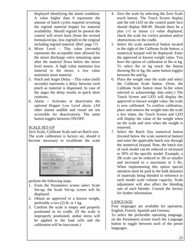
SCALE SET-UP Zero Scale, Calibrate Scale and set Batch size.
perform the following steps. 1. From the Parameters screen select Scale
Set-up; the Scale Set-up screen will be displayed.
2. Obtain an approved or a known weight, preferably a two (2) lb. or 1 kg.
3. Confirm the scale is empty and properly positioned in its cradle. (If the scale is improperly positioned, undue stress will be applied to the load cells and the
4. Zero the scale by selecting the Zero Scale
l face there be a
, nd/or
. Select the scale numerical button located ight of the Calibrate Scale button; a
le button. (Note, the Calibrate Scale button must hi-lite when
the
place and remove the weight onto the scale a few times, the Touch Screen and LED will display the value of the weight when on the scale and zero when the weight is removed.
7. Select the Batch Size numerical button (located below the scale numerical button) and enter the applicable batch size through the numerical keypad. Note, the batch size
ust be paid to the bulk densities
LA
The scale calibration is factory set, should it become necessary to recalibrate the scale
calibration will be inaccurate.)
touch button. The Touch Screen display and the red LED on the control paneshould display 000.00. Should plus (+) or minus (-) value displayedcheck the scale for correct position aobstructions on the cradle.
5to the rnumerical keypad will be displayed. Enter the approved or known weight value. You have the option of calibration in lbs or kg. To select lbs or kg touch the button showing lbs or kg, the same button toggles between lbs and kg.
6. Place the weight onto the scale and select the Calibrate Sca
selected to acknowledge data entry.) The Touch Screen and LED will displayapproved or known weight value, the scale is now calibrated. To confirm calibration,
of each model can be reduced or increased to 50% of the specific model. Example; a 2lb scale can be reduced to 1lb or smaller and increased to a maximum or 3 lbs. When implementing this option special attention mof materials being blended in reference to each model scale volume capacity. Scale adjustment will also affect the blending rate of each blender. Consult the factory for further information.
NGUAGE Four languages are available for operation,
To on butlang
English, French, Spanish and German. select the preferable operating language, the Parameters screen touch the Language ton to toggle between each of the preset uages.

24
MANUAL OPERATIONS
GXB Series 4 control has the ability to male, discharge the mixer and operate the mixeharge pinch valves, scale and mixer dischargted on each solenoid valve. Each solenoid va
The nually opsca r motor. disc e can be loca lve is ide
erate each dispensing valve, discharge the Also, all pneumatic operated components; activated by using the manual push buttons ntified for its component.
Manual Operation with Solenoid Valves. Manual Operation with GXB 4 Control Discharge Pinch Valves
OPEN each discharge pinch valve push in button and hold, to CLOSE release the
ton. Each button can be locked in the Open
To the butor Close position. To use the lock option, push
the the To turn
clos Sca
in the button and rotate clockwise a ½ turn, button will remain in the IN position and discharge pinch valve will remain open. release rotate the button clockwise a ½ , the button will return to the OUT
position and the discharge pinch valve will e.
le discharge ate the solenoid identified SCALELoc .
o OPEN the scale push in the button and release the button. Each
scale will r te the
return will close. Mixer disch
Thold, to CLOSEbutton can be locked in the Open or Close position. To use the lock option, push in the button and rotate clockwise a ¼ turn, the button will remain in the IN position and the
emain open. To release rotabutton clockwise a ½ turn, the button will
to the OUT position and the scale
arge e solenoid identified MIXER. Locate th
n the button and
butposition. To use the lock option, push in the
but n and the
butretuclos
Frothe
Dis
To OPEN the mixer push ihold, to CLOSE release the button. Each
ton can be locked in the Open or Close
button and rotate clockwise a ½ turn, the ton will remain in the IN positio
mixer will remain open. To release rotate the ton clockwise a ½ turn, the button will rn to the OUT position and the mixer will e.
m the Main Menu select Manual, to access Manual screen.
charge Pinch Valves OPEN a discharge pinch valve touch and in your finger on the desired numerical tified hopper. To CLOSE the discharge
ch valve remove your finger.
le discharge
To retaidenpin Sca
OPEN the scale, touch and retain your er on the Dump Scale button. To CLOSE scale, remove your finger.
er discharge
To fingthe Mix
OPEN the mixer, touch aTo nd retain your ump Mixer button. To CLOSE finger on the D
the mixer, remove your finger. Operate Mixer Motor To rotate the mixer blade, touch and retain your finger on the Mixer button. To stop rotation remove your finger.

REPORTS
tion report, atch report, Inventory report and Formulas stored report.
ports; or view of each blender running accuracies and material usage from batch to batch.
d by continuous scan of all conditions and maintained in a reports data ueste
The GXB Series 4 control provides a variety of reports for documentation of each blender’s production. All reports are identified with Date, Time, Model and Serial number for authenticity. The variety consists of; Cycle report, Diagnostic report, Cycle & Diagnostic combinaBThe Cycle and/or Diagnostic are very useful re they offer quick reference to the operator freAll reports data is collectefile, which is used, to generate each report as req CYCLE REPORT
d. See following sample reports.
The 1st. line identifies the type of report, date andnumber of the blender and the 3
timehe foonsis th entifies the percentage of s for
se lin
cle, th ercentage of the 1st l required, Virgin; the third column is the weig
the percentage of the 2nd material, ABS; the fifth is xth is the percentage of the 3rd material, Acrylic; theispensed. The eight is the percentage of the 4th mater eight of the
. The 2nd line identifies the model and serial ula the report is for. rd line identifies t
The 4rm
th line identifies the materials the formula ceach material in the formula and column headingwas performed. Below these lines are 15 columns of 25 lines; thesubtotal line of the 25 batch/cycles completed. The first column is the number of each Batch/Cymateria
ts of. The 5 line idthe total batch and the time the batch/cycle
es are the results of each batch/cycle and a
e second column is the pht of the virgin material dispensed. The fourth the weight of the ABS material dispensed. The seventh is the weight of the Acrylic material ial, Additive; the ninth is the w
issi
25d

26
Additive material dispensed. The tenth is the percentage of the 5th material, Additive*2; the eleventh is the weight of the Additive*2 material dispensed. The twelfth is the percentage of the 6th material, Color*; the thirteenth is the weight of the C ispensed. The fourteenth is the total weight of the batch/cycle completed and the fifteenth is the time the batch/cycle is completed.
e
From the Reports screen select Cycle. The Cycle Report will be displayed. The Continuous command must be set to ON. Select the Continuous OFF button located to the right of Cycle Report, the same button toggles On and Off. To set the cycle interval select the numerical button located to the right of Interval, from the pop-up numerical keypad enter the inteTo set the Subtotal select the number button located to the right of Subtotal. From the pop-up numerical keypad enter the subtotal number required. Example 25.
eports will be printed in the format shown on page 23, with each 10th completed cycle and the ccumulative subtotal of each 25th completed. Example, the first cycle print will be @ #10, the cond @ #20,the third @ #30 etc. and the first subtotal @ #25 cycle, the second @ #50, the third @
75 etc.
olor* material d
The Cycle report can be programmed to print batching intervals and subtotals, for example thbatching can be printed every 10th cycle and the subtotal every 25th cycle. This setting allows the operator to monitor the running condition of the blender while utilizing less paper. To program the Cycle report, follow these steps:
1. the Main Menu select Reports. From2. 3.
4. rval number required. Example 10.
5.
Rase#

DIAGNOSTIC REPORT The Diagnostic report shows the values of each material dispensed in grams providing the operawith information of cycle accuracies from batch to batch. Models, Serial number, Date and Time
tor are
Actual weight dispensed +/- Deviation dispensed
To program the Diagnostic report, follow these steps: 1. From the Cycle Report screen the Continuous command must be set to ON. Select the
Continuous OFF button located to the right of Diagnostic Report, the same button toggles On and Off.
2. To set the cycle interval select the numerical button located to the right of Interval, from the pop-up numerical keypad enter the interval number required. Example 10.
The control will print each 10th completed cycle. Example, the first cycle print will be @ #10, the second @ #20,the third @ #30 etc. Reports will be printed in the format shown.
all part of each report. (DSP data is displayed at the bottom left of the screen). Material Name Material flow (numerical value) Target weight requested
27

28
Cycle reports can be printed separately or in combination with each NOTE: Both Diagnostic and other. To print both reports, select Cycle and Diagnostic Reports, Continuous ON. Intervals printing and Subtotals will function (when programmed) as previously described. The combination report will be printed in the format as shown below:

BATCH REPORT The Batch report shows the total amount and error of each material processed in a specific formula,
report.
1. From the Main Menu select the Reports button. 2. From the Reports screen select the Batches button. A numerical keypad will be displayed, enter
the number of the formula you require printing. The formula and all revisions will be printed. Reports will be printed in the format shown.
The first column consists of the materials processed. The second column consists of the requested percentage of each material processed. The third column consists of the actual percentage of each material processed. The fourth column consists of the total amount of each material processed in their set value; ounces, grams, pounds or kilograms. Also the total of all materials processed. The fifth column consists of the total error in percentage of each material processed.
including all its revised formulas. Models, Serial number, Date and Time are all part of eachTo print the Batch Report, follow these steps:
29

FORMULA REPORT
30
elected formulas stored in memory can be printed.
1. From2. From3. From selected formula by navigating thru the list of
for hen the formula required is identified select the
4. ulas identify the first formula by navigating thru the list of for ect the Set First button. Identify the last formula by navigating thru the list of formulas using the up and down scroll buttons, select the Set Last button. Select the print button, the selected formulas and all revisions will be printed.
5. To quickly find a formula when numerous formulas are stored select the Formula button, a numerical keypad will be displayed, enter the number of the formula you require, it will be displayed in the list ready for further selections.
6. To view a formula select the required formula theReports will be printed in the format shown.
All formulas and/or sThe Formula report shows specifications of each formula, including all its revised formulas. Models,Serial number, Date and Time are all part of each report. To print the Formula report, follow these steps:
the Main Menu select the Reports button. Reports screen select formula. the Formula Reports screen you can print a
mulas using the up and down scroll buttons, wprint button. To print a specific range of form
mulas using the up and down scroll buttons, sel
n select the View button.

INVENTORY REPORT
31
On tmate
4.
that the operator
ll materials inventory will be deleted when selected. Deletion of individual materials is not vailable. PROCEED WITH CAUTION. eports will be printed in the format shown.
ll of the afore mentioned reports requires a parallel printer connected to the printer port of the ontrol panel.
All materials usage stored in memory can be viewed and/or printed. 1. To view or print materials inventory select Reports from the Main Menu. 2. From the Reports screen select Inventory.
he Inventory Report screen you have the selection of viewing, printing and deleting the rials inventory.
3. To view each material usage from the total material list, scroll up and down (as required) byselecting the Next button or the Prev. button. To print the reports select the Print button.
5. To delete the inventory select the Delete button. displayed requesting confirmationNote: When Delete is selected a query will be
does indeed wish to delete the inventory. AaR Ac
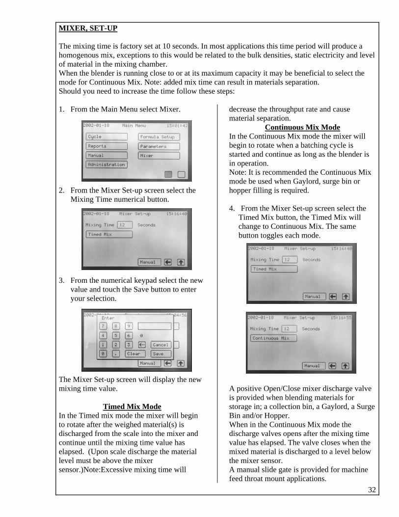
MIXER, SET-UP The mixing time is factory set at 10 seconds. In most applications this time pe
related to the bulk densities, stariod will produce a tic electricity and level
aximumode for Continuous Mix. Note: added mix me can result in materials separation. Should you need to increase the time follow these steps: 1. From the Main Menu select Mixer.
. FromMixing Time num
he Mixer Set-up screen will display the new ixing time value.
homogenous mix, exceptions to this would be of material in the mixing chamber. When the blender is running close to or at its m m capacity it may be beneficial to select the
ti
32
2 the Mixer Set-up screen select the
erical button. 3. From the numerical keypad select the new
value and touch the Save button to enter your selection.
Tm
Timed Mix Mode In the Timed mix mode the mixer will begin
e mixing time value has lapsed. (Upon scale discharge the material vel must be above the mixer nsor.)Note:Excessive mixing time will
decrease the throughput rate and cause material separation.
Continuous Mix Mode
to rotate after the weighed material(s) is discharged from the scale into the mixer and ontinue until th
In the Continuous Mix mode the mixer will begin to rotate when a batching cycle is started and continue as long as the blender is in operation. Note: It is recommended the Continuous Mix mode be used when Gaylord, surge bin or hopper filling is required. 4. From the Mixer Set-up screen select the
will e
A positive Open/Close mixer discharge valve is provided when blending materials for storage in; a collection bin, a Gaylord, a Surge Bin and/or Hopper.
e value has elapsed. The valve closes when the mixed material is discharged to a level below the mixer sensor. A manual slide gate is provided for machine feed throat mount applications.
celese
Timed Mix button, the Timed Mix change to Continuous Mix. The sambutton toggles each mode.
When in the Continuous Mix mode the discharge valves opens after the mixing tim

TROUBLE SHOOTING GUIDE
PROBLEM POSSIBLE CAUSE SOLUTION
• • No Power Power cord not connected. • Fuse or circuit breaker has failed.
• Connect power cord. • Replace fuse or reset circuit breaker.
• Material did not • Material not selected in formula. • Reprogram formula tdispense. • Air failure.
• Dispense pneumatic valve cylinder
in hopper. • Dispense pneumatic solenoid
and/or coil failed.
o include material. • Re-establish air supply. • Replace dispense valve pneumatic
noid
failed. • Obstruction
valve
cylinder. • Remove obstruction. • Replace pneumatic dispense sole
valve and/or coil. Individual materials
dispense alarm activated.
• Insufficient Material Feed Atime value.
• Plugged material feed throat• Dispense pneumatic valve c
failed. • Dispense pneumatic solenoi
#21.
place dispense valve pneumatic
• larm
. ylinder
• Increase Material Feed Alarm time value. Maximum 60 seconds. Page
• Remove obstruction. • Re
d valve cylinder.
• Replace dispense pneumatic solenoid valve and/or coil. and/or coil failed.
• Batch time alarm activated.
• Insufficient Batchvalue.
time alarm
• Low air pressure supply. • Scale out of calibration.
me alarm value. • Increase Batch tiMaximum 255 seconds. Page #21.
• Increase & maintain 60 P.S.I. • Recalibrate scale. Page #22.
Scale does not zero, displays +/0 value when empty.
• Obstruction to load cell arms. • Scale out of calibration. • Defective load cell.
. e #22. recalibrate scale.
• • Remove obstruction and recalibrate• Recalibrate scale. Pag• Replace load cell and
Scale discharge valve does not Open or Close.
• Defective pneumatic discharge valve cylinder.
• Disconnected air supply. • Defective solenoid valve and
• Replace pneumatic discharge valve cylinder.
• Reconnect air supply. • Replace solenoid valve and/or coil.
•
/or coil.
• • Defective electrical relay. • Damaged mixer agitator. • Defective mixer access door afety
switch.
• Replace motor. • Replace electrical relay. • Replace mixer agitator. • Replace mixer access door safety switch.
Mixer failure. • Defective motor.
s
Mixer discharge failure.
• Defective discharge pneuma cylinder.
• Defective pneumatic solenoi valve and/or coil.
• Air Flow is low. • Disconnected air supply.
• Replace discharge pneumatic cylinder. • Replace pneumatic solenoid valve
and/or coil. • Adjust airflow control fitting. • Reconnect air supply.
• tic
d
• Touch screen white out or black out.
• Contrast too bright or dark. • Adjust bright or dark contrast buttons. Page #11.
• Blender stopped while in operation. (Stop function not
• Power failure. • mode selected.
et Batch count completeand mod nd mode resets automatically
selected). Pause
• Pres d. e.
• Restore power. • Deselect pause mode. Page #9, item #5. • See page #10. • No Dema• Blender in No Dem
when mixer discharges. • Mixer over fills. • Level sensor out o
• Defective mixer lef adjustmevel sensor
nt. .
• Readjust sensor. • Replace mixer level sensor.
• Running formula changed to 100% Virgin material.
• SMART Mode activated. • See page #18 and follow instructions.
For further assistance contact your s 33
upplier or the factory.

34
MAINTENANCE
our GXB Series 4 blender is constructed of a heavy-duty frame; hoppers, scale and load cell assem aintain a sturd ture.
l l and electri l common d ard maintenance practices are q
e comme• al Control Panel nel door closed to ma
use sharp or metal obje s p or fix nylon material conveying hose in close proximity of the e control panel close to any hea u rr ,
• Load cell and cradle s ls estan a mo a
se is not rec . Should load cells be subsalignment o x e abilit o
will be greatly affected arereplacement use the sa
• Scale hopper – It is im pp e scale hopp the
accurately weigh the materials will be greatly affecte oper replacement. To prope p and pull t
• Scale hopper dischar to maintain u assembly Sho d assem y
ely o tly affected o
ixer agitator free from dar place heavy ob c r. Should th m e irregular in
shape the ability to pro r great a a proper replacement.
r – Your blender is provided with a fan-coole t the rear of the motor). It is important k y obstructi s circulation, which may cause the m to or r
• Mixer discharge – Your blender is pbly. P o for b ld
bly erating efficiently. Remo e all obstructions. • Compressed Air supply u ir The
air pressure regulator is p th a water trap, drain periodically. Should the solenoid stack become contaminated th ormance o and may
s) fa rmbl s – Each pin ion as
t perform t to keep the pinch ess bu - t; stringers, re in
an cl• Pinch Valve sleeves – a ade of si
withstand a heat range of up to 400 Deg. F. Insp onth cessary p factur r
e s desig d le free erequired to prevent unnecessary failures a achine operation. Failure to adhere to the above procedures will void all warranties.
For further assistance contact your supplier or the factory.
Yblies all to m y integral secure struc
Al mechanica ca components utilized are in ustrial types. Stand re uired.
Th following is reElectric
nded for the items listed: – Keep pa intain a dust free condition. Do not
ct to operate the touch screen. To revent static conditions do not layn pa el. Do not locate th
t so rce such as metering heater baa sembly – Although the load cel
els motors and electrical heaters. ar delicate instruments the assembly
is designed to withexcessive abucradle mi
d nd protect each load cell fromommended
st dverse conditions, however jected to excessive force due to
r e cessive weight applied, th y t accurately weigh the materials . Periodically check that all bolts
a secure. Should any bolts require
me s the manufacturer provided. portant to maintain your scale ho er free from damage. Do not drop or
place heavy objects on thability to
scale hopper. Should the er become irregular in shape d. Contact the factory for a pr
rly remove the scale lift u ou towards you. ge gate - It is important yo r scale hopper discharge
free from damage.ability to effectiv
ul the scale hopper discharge bl become irregular in shape, the pen and close will be grea . C ntact the factory for a proper
replacement. • Mixing agitator – It is important to m
drop oaintain your m mage. Do not
je ts on the mixer agitato e ixer agitator becompe ly mix the materials will be ly ffected. Contact the factory for
• Mixer moto d motor (fan located a to eep the fan clear of an on preventing proper airo r to overheat and result in mot
rovided with a pneum bu n out. atic positive open and close mixer
discharge assemwill prevent the assem
eri dically inspect the assembly from op
ui -up of material stringers, which v
– It is important to maintain yorovided wi
r a system free of water and oil.
wi water and oil the perf f the blender will be affected result in solenoid(
• Pinch Valve asseilu e. ie ch valve is a precis sembly and will withstand a variety
of adverse conditions. However to ensure efficienvalve free of excPeriodically inspect
ance it is importanild up of materials dus gr d granular and pellets. d ean each valve assembly. E ch pinch valve sleeve is m a licone compound which will
ect each pinch valve sleeve once every 6 muperiod and if ne re lace with an original man
rouber eplacement only.
Th GXB Series 4 i ne to give you years of tnd maintain efficient m
op ration. Regular maintenance is

35
All specifications are
subject to change without notice.

All specifications are subject to change without notice.
36
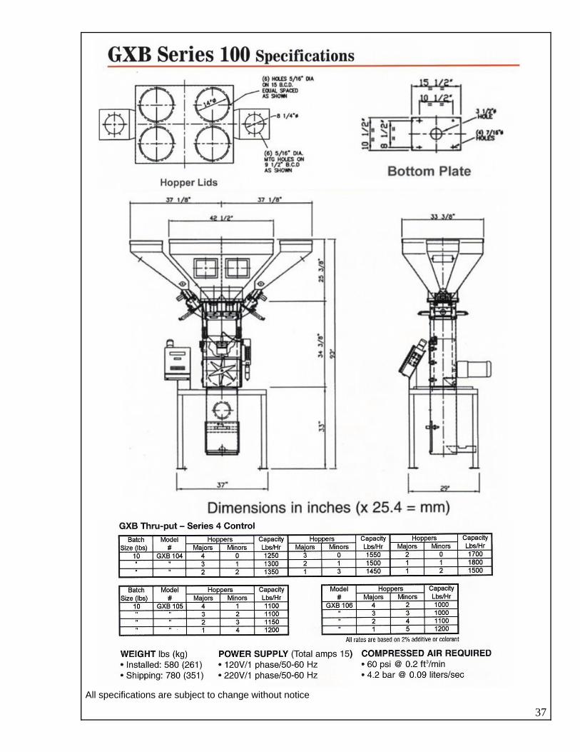
All specifications are subject to change without notice
37

All specifications are subject to change without notice.
38

39
All specifications are subject to change without notice.

40
Dimensions in inches (X 25.4 = mm)
. All specifications are subject to change without notice

41

42

43

44
45 45