gravityfusion: real-time dense mapping without pose...
TRANSCRIPT

GravityFusion: Real-time Dense Mapping without Pose Graph usingDeformation and Orientation
Puneet Puri1, Daoyuan Jia2, and Michael Kaess1
Abstract— In this paper, we propose a novel approach tointegrating inertial sensor data into a pose-graph free densemapping algorithm that we call GravityFusion. A range of densemapping algorithms have recently been proposed, though fewintegrate inertial sensing. We build on ElasticFusion, a partic-ularly elegant approach that fuses color and depth informationdirectly into small surface patches called surfels. Traditionalinertial integration happens at the level of camera motion,however, a pose graph is not available here. Instead, we presenta novel approach that incorporates the gravity measurementsdirectly into the map: Each surfel is annotated by a gravitymeasurement, and that measurement is updated with eachnew observation of the surfel. We use mesh deformation, thesame mechanism used for loop closure in ElasticFusion, toenforce a consistent gravity direction among all the surfels.This eliminates drift in two degrees of freedom, avoiding thetypical curving of maps that are particularly pronounced inlong hallways, as we qualitatively show in the experimentalevaluation.
I. INTRODUCTION
Combining dense 3D mapping with inertial sensing pro-vides significant advantages over pure vision-based mapping.Dense 3D maps are relevant for mobile robot navigation andmanipulation, for augmented and virtual reality applications,and for inspection tasks. And while most dense mappingsystems rely on only stereo or RGB-D cameras, inertialsensors are becoming ubiquitous because of their low costand wide range of applications.
In the absence of a global reference such as GPS, mappingalgorithms suffer from drift, which can partially be mitigatedby loop closures in a simultaneous localization and mapping(SLAM) context. Drift results from the accumulation of noisysensor data over time, where small errors add up over longertrajectories to yield significant discrepancies between themodel and the physical world. A typical solution to reducingdrift is loop closure: When we re-observe a previously visitedarea of the environment, we can create a constraint betweenthe earlier observations and the current sensor data, a loopclosure, that allows removal of some of the accumulated drift.
Incorporating loop closures into dense mapping requiresthe right model representation: Volumetric representationsare not suitable, as translation and rotation of parts of themodel is computationally very expensive. Surface mesh rep-resentation on the other hand can be deformed at relativelylow cost, but re-integrating two surface meshes after loop
1P. Puri and M. Kaess are with the Robotics Institute,Carnegie Mellon University, Pittsburgh, PA 15213, [email protected], [email protected]
2D. Jia is with the Language Technology Institute, Carnegie MellonUniversity, Pittsburgh, PA 15213, USA [email protected]
Fig. 1. GravityFusion produces a consistent model through a low-featurecorridor circuit, where other methods fail.
closure is challenging. The surfel representation used inElasticFusion allows for both, efficient deformation and re-integration upon loop closure. We therefore use ElasticFusionas the basis for our work.
Even with loop closures, some drift remains, and addi-tional measurements, such as from an inertial sensor, areneeded to obtain accurate models. When mapping a singlefloor of a building there is typically insufficient data toconstrain drift in some directions, yielding a curved map.The poorly constrained degrees of freedom include pitch,roll and z, while drift in x, y and yaw is bounded by theloop closures. Incorporating additional sensor informationcan help in limiting that drift. Inertial sensors provide com-plementary information: by providing an estimate for thegravity direction, they eliminate drift in pitch and roll.
Our contribution is a novel algorithm that integrates in-ertial measurements directly into the map. Since the Elas-ticFusion algorithm is pose-free, conventional inertial fusionalgorithms cannot be applied. Instead, we fuse inertial mea-surements inside the map. We then use a mesh deformationtechnique, used in ElasticFusion for loop closing, to enforcea consistent gravity direction over the entire map, and therebyeliminating much of the drift from the map.
II. RELATED WORK
Various dense mapping techniques have been proposedover the past several years. One approach, BundleFusionby Dai et al. [2], uses bundle adjustment for global framealignment combined with dense map generation, making itvery accurate but computationally expensive. Probabilisticformulations account for estimation uncertainty and includeREMODE by Pizzoli et al. [14] as well as planar mapping
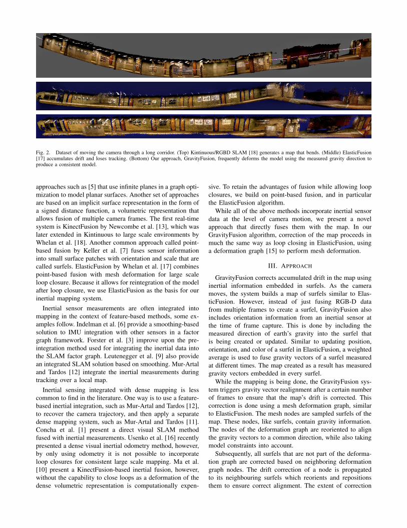
Fig. 2. Dataset of moving the camera through a long corridor. (Top) Kintinuous/RGBD SLAM [18] generates a map that bends. (Middle) ElasticFusion[17] accumulates drift and loses tracking. (Bottom) Our approach, GravityFusion, frequently deforms the model using the measured gravity direction toproduce a consistent model.
approaches such as [5] that use infinite planes in a graph opti-mization to model planar surfaces. Another set of approachesare based on an implicit surface representation in the form ofa signed distance function, a volumetric representation thatallows fusion of multiple camera frames. The first real-timesystem is KinectFusion by Newcombe et al. [13], which waslater extended in Kintinuous to large scale environments byWhelan et al. [18]. Another common approach called point-based fusion by Keller et al. [7] fuses sensor informationinto small surface patches with orientation and scale that arecalled surfels. ElasticFusion by Whelan et al. [17] combinespoint-based fusion with mesh deformation for large scaleloop closure. Because it allows for reintegration of the modelafter loop closure, we use ElasticFusion as the basis for ourinertial mapping system.
Inertial sensor measurements are often integrated intomapping in the context of feature-based methods, some ex-amples follow. Indelman et al. [6] provide a smoothing-basedsolution to IMU integration with other sensors in a factorgraph framework. Forster et al. [3] improve upon the pre-integration method used for integrating the inertial data intothe SLAM factor graph. Leutenegger et al. [9] also providean integrated SLAM solution based on smoothing. Mur-Artaland Tardos [12] integrate the inertial measurements duringtracking over a local map.
Inertial sensing integrated with dense mapping is lesscommon to find in the literature. One way is to use a feature-based inertial integration, such as Mur-Artal and Tardos [12],to recover the camera trajectory, and then apply a separatedense mapping system, such as Mur-Artal and Tardos [11].Concha et al. [1] present a direct visual SLAM methodfused with inertial measurements. Usenko et al. [16] recentlypresented a dense visual inertial odometry method, however,by only using odometry it is not possible to incorporateloop closures for consistent large scale mapping. Ma et al.[10] present a KinectFusion-based inertial fusion, however,without the capability to close loops as a deformation of thedense volumetric representation is computationally expen-
sive. To retain the advantages of fusion while allowing loopclosures, we build on point-based fusion, and in particularthe ElasticFusion algorithm.
While all of the above methods incorporate inertial sensordata at the level of camera motion, we present a novelapproach that directly fuses them with the map. In ourGravityFusion algorithm, correction of the map proceeds inmuch the same way as loop closing in ElasticFusion, usinga deformation graph [15] to perform mesh deformation.
III. APPROACH
GravityFusion corrects accumulated drift in the map usinginertial information embedded in surfels. As the cameramoves, the system builds a map of surfels similar to Elas-ticFusion. However, instead of just fusing RGB-D datafrom multiple frames to create a surfel, GravityFusion alsoincludes orientation information from an inertial sensor atthe time of frame capture. This is done by including themeasured direction of earth’s gravity into the surfel thatis being created or updated. Similar to updating position,orientation, and color of a surfel in ElasticFusion, a weightedaverage is used to fuse gravity vectors of a surfel measuredat different times. The map created as a result has measuredgravity vectors embedded in every surfel.
While the mapping is being done, the GravityFusion sys-tem triggers gravity vector realignment after a certain numberof frames to ensure that the map’s drift is corrected. Thiscorrection is done using a mesh deformation graph, similarto ElasticFusion. The mesh nodes are sampled surfels of themap. These nodes, like surfels, contain gravity information.The nodes of the deformation graph are reoriented to alignthe gravity vectors to a common direction, while also takingmodel constraints into account.
Subsequently, all surfels that are not part of the deforma-tion graph are corrected based on neighboring deformationgraph nodes. The drift correction of a node is propagatedto its neighbouring surfels which reorients and repositionsthem to ensure correct alignment. The extent of correction
is based on vicinity to a correcting graph node. It is possiblethat multiple nodes affect a surfel and contribute to itsreorientation and repositioning. Since these corrections aredone for all surfels throughout the map, in the end we get amap which is drift corrected.
Frequent gravity-based map corrections are performed inreal-time. While ElasticFusion applies graph deformationonly at loop closure, we regularly perform a mesh deforma-tion to incorporate gravity measurements and eliminate drift.To allow for real-time processing, the gravity correction isadded to the GPU-based loop closure algorithm in Elastic-Fusion. Consequently, a good map is always available in ourpose-graph-free approach, without the need to maintain paststates or deal with issues often related to the marginalizationof previous state information.
IV. MAP CREATION
The mapping process in GravityFusion resembles Elastic-Fusion’s with changes in camera tracking method and mapdata structure. The map is represented as an unordered surfellist similar to Whelan et al. [17] and Keller et al. [7]. Asurfel S consists of gravity vector g ∈ R3, position v ∈ R3,normal n ∈ R3, color c ∈ N3, confidence λ ∈ R, radiusr ∈R, initialization timestamp t0 and last updated timestampt. Sections A and B explain how inertial information isintegrated into the tracking and mapping systems.
A. Tracking
Our camera tracking approach closely resembles Elastic-Fusion’s [17] where combined depth tracking and photomet-ric alignment is initialized with photometric alignment only.Our approach differs as it informs this photometric alignmentwith an inertial measurement from the IMU rotation, thusleading to a more robust camera pose estimation. We onlymake use of rotation values from the inertial data becauseincremental angular motion is available with greater accuracyusing standard IMUs.
In the RGB-D incoming frame we define the imagedomain as Ω⊂N2 and the depth map D as the depth of pixelsd : Ω→ R. The 3D back-projection of a point u ∈ Ω for agiven depth map D is given by p(u,D) = K−1ud(u), whereK is the camera intrinsic matrix and u is the homogeneousform of u. The perspective projection of a 3D point p =[x,y,z]> (in camera frame Fc), is represented as u = π(Kp).Here π(p) = [x/z,y/z]> represents the de-homogenizationoperation. The normal map is computed for every depth mapusing central differences.
The color image C is represented as c : Ω → N3. Thecolor-intensity value of a pixel u ∈ Ω, given a color imageC with color c(u) = [c1,c2,c3]
>, is defined as I(u,C) =(c1+c2+c3)/3. The global pose of the camera Pt (in globalframe Fg) is determined by live registration of a depth mapand a color frame with the model. The pose estimationiteratively minimizes tracking error Etracking as a weightedsum of geometric error Eicp and photometric error Ergb.These errors are calculated between the raw live depth mapDt from the sensor and the active model’s depth map using
the last frame, Dt−1, in order to find the optimal motionparameter ξ , where ξ ∈R6 and exp(ξ )∈ SE(3). The trackingerror is expressed as
Etracking = Eicp +ωrgbErgb, (1)
Eicp = ∑k((vk− exp(ξ )T.vk
t ).nk)2, (2)
Ergb = ∑u∈Ω
(I(u,Ct − I(π(K exp(ξ )Tp(u,Dt)),Ct−1)))2 , (3)
where ωrgb is the weight of photometric error Ergb over ICPerror Eicp. Here, vk
t is the back-projection of the kth vertexin Dt , vk represents the corresponding vertex in the model,and nk is the normal of vk. T is the current estimation oftransformation of camera pose and exp(ξ ) is the incrementalmotion with parameter ξ to be optimized in the currentiteration. Similarly the color from the live frame Ct at thecurrent time t and model Ct−1 is used to find the optimummotion parameter ξ using photometric error—the intensitydifference between pixels. For more detailed understandingof the above equations we refer to Whelan et al. [17].
Similar to ElasticFusion, the energy terms from (2) and(3) are jointly optimized to calculate the least squares so-lution for the optimal ξ to get an accurate camera poseestimate Pt = exp(ξ )TPt−1. Unlike ElasticFusion, before theoptimization begins, the initial estimate T is modified toincorporate the measured inertial-orientation Rimu ∈ SO(3)for a more accurate initialization of T. We call this the SO(3)initialization step.
B. Adding Inertial Information into Surfels
The inertial information is incorporated into the map byembedding gravity direction into every surfel. This is doneas the frame is being aligned and fused to the model.To orient the gravity vector into the model frame, a unitvector [0,0,1]>, in model frame, is transformed into theIMU (camera) frame using the inertial readings from theIMU. The inertial data (orientation) is obtained as filteredoutput of an attitude heading reference system (AHRS) ofthe IMU, denoted as Rimu. We denote this gravity vector inIMU frame as gi
imu ∈ R3 where i ∈ R is the surfel’s index.We then transform gi
imu back to the model frame using thetracking estimate of the camera orientation represented asRtracking ∈ SO(3). We denote this gravity vector as gi
model .The gi
model is added into every surfel, providing constraintson two degrees of freedom from the inertial measurements.
giimu = (Rimu)
−1 [0 0 1]> (4)
gimodel = Rtrackinggi
imu (5)
C. Updating Gravity Direction Information
When new frames are fused to the model, surfels areupdated for gravity, position, normal and radius according tothe confidence of the current and incoming surfels, similarto ElasticFusion. The surfel correspondences are built withmap registration of the incoming frame. A confidence valueλ is initialized along with the creation of the surfel andaccumulates each time we observe the same surfel in the
camera frame. The confidence parameter acts as a weight: ameasure of the extent to which we should retain the surfelin an update. The update equations for the surfel parameter,given the new incoming surfel’s parameters, gravity directiong′, position v′, normal n′ and confidence λ ′ are:
g =λ ·g+λ ′ ·g′
λ +λ ′(6)
n =λ ·n+λ ′ ·n′
λ +λ ′(7)
v =λ ·v+λ ′ ·v′
λ +λ ′(8)
λ = λ +λ′ (9)
The updated gravity direction g of the surfel is a weightedaverage of the current estimate with the gravity reading ofthe incoming surfel g′.
V. MAP CORRECTION: GRAVITY BASED DEFORMATIONGRAPH
To correct the model for drift and tracking inconsistencieswe use a deformation graph. The deformation model usedhere is general enough to be applied to any map and stillprovides intuitive manipulation while preserving surface con-sistency. This formulation allows stretching and realignmentof the map while maintaining surface continuity. The nodesof the deformation graph are created by sampling existingsurfels from a full model. As a result, the graph createdis a sparse model of the original map. The deformation ofthis graph is a set of affine transformations of graph nodesproviding spatial reorganization. These affine transformationinfluence the neighboring nodes, having an overlapping ef-fect.
Our deformation graph is similar to that in Sumner et al.[15] and Whelan et al. [17] with an essential addition thateach node contains inertial information in the form of gravitydirection. A single graph node contains a gravity vector Gg ∈R3, its position Gp ∈ R3 and a timestamp. The graph nodealso stores an affine transformation as rotation GR ∈ SO(3)and translation Gt ∈ R3 to be applied to itself, while alsoinfluencing surfels and graph nodes in its neighborhood. Thisaffine transformation is initialized as Gt = 000 and GR = I atthe time of graph creation, and again after completion ofgraph optimization. We consider the total number of graphnodes to be m and each having at most K neighbors. Asexplained in below subsections, the influence of graph nodescan be broken down into two stages: firstly, how graphnodes affect surfels in their vicinity, as shown in Fig. 3 andsecondly, how graph nodes influence each other during graphoptimization for deformation as shown in Fig. 4.
A. Influence of Deformation Graph on Surfels
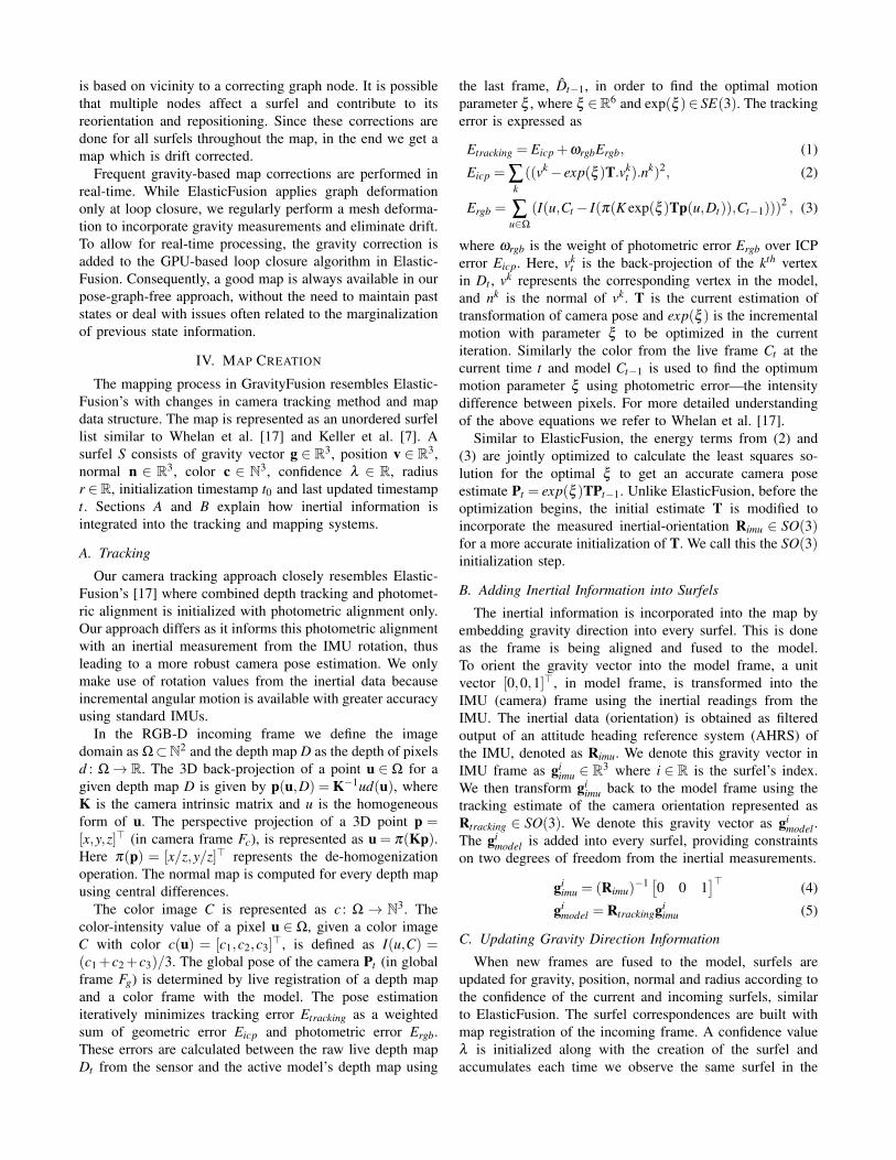
An affine transformation of a graph node is centeredaround itself. As a graph node rotates (GR) and translates(Gt ), its influence causes the nearby surfels to spatiallyreorient. The effect of graph node’s affine transformation ona nearby surfel at location v is shown in Fig. 3. This principle
Fig. 3. Influence of affine transformation (GR,Gt ) of a graph node (ingreen) on a neighboring surfel (in blue) by spatially reorienting the surfelto a new location.
is used throughout the deformation graph to obtain the newlocation v given by:
v = GR(v−Gp)+Gp +Gt (10)
The extent of this influence is limited by the distance of surfeli from the graph node j. The influence here is representedas a weight w j
w j(vi) = (1−||vi−G jp||/dmax), (11)
where dmax is the distance of the surfel to the Kth nearestgraph node. To smoothly blend the effect of multiple graphnodes on a surfel, we sum over the combined influence. Theresultant final position of the surfel is written as
vi =m
∑j=1
w j(vi)G jR(vi−G j
p)+G jp +G j
t (12)
Any rotation applied to a surfel effect the orientation ofits normal ni. Similar to the position update, the combinedinfluence of graph node’s rotation on the surfel’s orientationis expressed as
ni =m
∑j=1
w j(vi)(G jR)−1ni (13)
As surfel and its normal orientation get updated, a similarupdate is applied to the gravity direction associated with thatsurfel. This update ensures that after deformation the gravitydirection remains consistent to the surfel’s orientation.
gi =m
∑j=1
w j(vi)(G jR)−1gi (14)
We sample the graph nodes densely, ensuring that graphnodes have an accurate representation of the entire map. Thisdense sampling assures that when deformation is applied, itsinfluence reaches all desired surfels in the map.
B. Optimization of Deformation Graph
We optimize the deformation graph to find the affinetransformation of graph nodes, which when applied to ourmodel will correct its drift and make it consistent. Thisoptimization utilizes the direction of gravity vectors in the
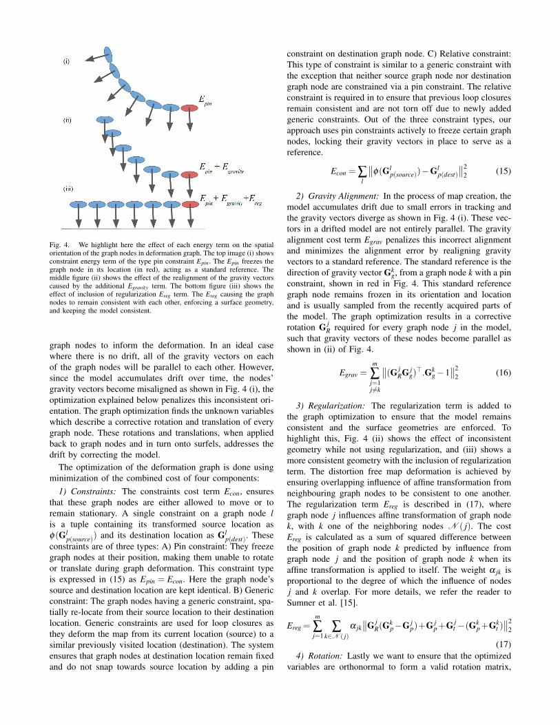
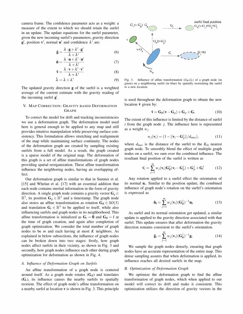
Fig. 4. We highlight here the effect of each energy term on the spatialorientation of the graph nodes in deformation graph. The top image (i) showsconstraint energy term of the type pin constraint Epin. The Epin freezes thegraph node in its location (in red), acting as a standard reference. Themiddle figure (ii) shows the effect of the realignment of the gravity vectorscaused by the additional Egravity term. The bottom figure (iii) shows theeffect of inclusion of regularization Ereg term. The Ereg causing the graphnodes to remain consistent with each other, enforcing a surface geometry,and keeping the model consistent.
graph nodes to inform the deformation. In an ideal casewhere there is no drift, all of the gravity vectors on eachof the graph nodes will be parallel to each other. However,since the model accumulates drift over time, the nodes’gravity vectors become misaligned as shown in Fig. 4 (i), theoptimization explained below penalizes this inconsistent ori-entation. The graph optimization finds the unknown variableswhich describe a corrective rotation and translation of everygraph node. These rotations and translations, when appliedback to graph nodes and in turn onto surfels, addresses thedrift by correcting the model.
The optimization of the deformation graph is done usingminimization of the combined cost of four components:
1) Constraints: The constraints cost term Econ, ensuresthat these graph nodes are either allowed to move or toremain stationary. A single constraint on a graph node lis a tuple containing its transformed source location asφ(Gl
p(source)) and its destination location as Glp(dest). These
constraints are of three types: A) Pin constraint: They freezegraph nodes at their position, making them unable to rotateor translate during graph deformation. This constraint typeis expressed in (15) as Epin = Econ. Here the graph node’ssource and destination location are kept identical. B) Genericconstraint: The graph nodes having a generic constraint, spa-tially re-locate from their source location to their destinationlocation. Generic constraints are used for loop closures asthey deform the map from its current location (source) to asimilar previously visited location (destination). The systemensures that graph nodes at destination location remain fixedand do not snap towards source location by adding a pin
constraint on destination graph node. C) Relative constraint:This type of constraint is similar to a generic constraint withthe exception that neither source graph node nor destinationgraph node are constrained via a pin constraint. The relativeconstraint is required in to ensure that previous loop closuresremain consistent and are not torn off due to newly addedgeneric constraints. Out of the three constraint types, ourapproach uses pin constraints actively to freeze certain graphnodes, locking their gravity vectors in place to serve as areference.
Econ = ∑l
∥∥φ(Glp(source))−Gl
p(dest)
∥∥22 (15)
2) Gravity Alignment: In the process of map creation, themodel accumulates drift due to small errors in tracking andthe gravity vectors diverge as shown in Fig. 4 (i). These vec-tors in a drifted model are not entirely parallel. The gravityalignment cost term Egrav penalizes this incorrect alignmentand minimizes the alignment error by realigning gravityvectors to a standard reference. The standard reference is thedirection of gravity vector Gk
g, from a graph node k with a pinconstraint, shown in red in Fig. 4. This standard referencegraph node remains frozen in its orientation and locationand is usually sampled from the recently acquired parts ofthe model. The graph optimization results in a correctiverotation G j
R required for every graph node j in the model,such that gravity vectors of these nodes become parallel asshown in (ii) of Fig. 4.
Egrav =m
∑j=1j 6=k
∥∥(G jRG j
g)>.Gk
g−1∥∥2
2 (16)
3) Regularization: The regularization term is added tothe graph optimization to ensure that the model remainsconsistent and the surface geometries are enforced. Tohighlight this, Fig. 4 (ii) shows the effect of inconsistentgeometry while not using regularization, and (iii) shows amore consistent geometry with the inclusion of regularizationterm. The distortion free map deformation is achieved byensuring overlapping influence of affine transformation fromneighbouring graph nodes to be consistent to one another.The regularization term Ereg is described in (17), wheregraph node j influences affine transformation of graph nodek, with k one of the neighboring nodes N ( j). The costEreg is calculated as a sum of squared difference betweenthe position of graph node k predicted by influence fromgraph node j and the position of graph node k when itsaffine transformation is applied to itself. The weight α jk isproportional to the degree of which the influence of nodesj and k overlap. For more details, we refer the reader toSumner et al. [15].
Ereg =m
∑j=1
∑k∈N ( j)
α jk∥∥G j
R(Gkp−G j
p)+G jp+G j
t −(Gkp+Gk
t )∥∥2
2
(17)4) Rotation: Lastly we want to ensure that the optimized
variables are orthonormal to form a valid rotation matrix,

Fig. 5. Our camera setup: ASUS Xtion Pro Live with Microstrain 3DM-GX4-25.
which is enforced by
Erot =m
∑j=1
∥∥(G jR)>(G j
R)− I∥∥2
2 (18)
The complete graph deformation is based on optimizationof a combined sum of all the components explained above.The weight coefficients control the effect of each energyterm:
minG1
R..GmR ,
G1t ..Gm
t
ωconEcon +ωregEreg +ωrotErot +ωgravEgrav (19)
In our experiments, we set ωrot = 1, ωreg = 10, ωcon = 100,and ωgrav = 100. We minimize the weighted energy term w.r.teach graph node’s rotation G j
R, j≤m and translation G jt , j≤
m using an iterative Gauss-Newton method. The rotation andtranslation calculated are used in (12), (13), and (14) to alignthe model for correction.
C. Triggering Graph Optimization
We trigger graph optimization to correct for drift aftera fixed interval of frames (Ct=500). This frequent graphoptimization ensures that gravity constraints are enforcedeven if no loop closure occurs. In the event of local andglobal loop closure, we trigger graph optimization similar toElasticFusion. For details on local and global loop closurewe refer to Whelan et al. [17]
VI. RESULTS
We evaluate the performance of our system qualitativelyusing data from different real-world environments such ashallways and office alleys. We also present a quantitativesurface evaluation on a public dataset in subsection B.
A. Evaluation on Real-world Data
Our hardware setup is a combination of an RGB-D camera(ASUS Xtion Pro Live) and an IMU (Microstrain 3DM-GX4-25) as shown in Fig. 5. We use filtered output of inertialreadings from a Microstrain 3DM-GX4-25 sensor.
We focus qualitative testing on long corridors instead ofsmall room environments. In long hallway type environmentoften dense methods without pose graph fail, as slow driftin map registration causes bending, or lack of features causeloss of tracking due to incorrect photometric alignment. Weshowcase our system’s versatility as it performs well invarious environments such as: a) Long corridor with featuresb) Corridors with fewer features c) Corridors with loops andd) Office desk environment.
1) Experiment for Drift Correction: We capture datathrough a long corridor which has significant features. Fig. 2shows the comparison among models generated from varioussystems. The Kintinuous/RGB-D SLAM [18] in Fig. 2 (top)tracks successfully, however, due to drift accumulation, thereis a significant bend in the corridor map. The ElasticFusionin Fig. 2 (center) suffers both from drift accumulation andloss of tracking. Our system in Fig. 2 (bottom) creates aconsistent map, generating a straight corridor.
2) Experiment for Tracking Correction: For qualitativeevaluation of tracking, we do a 4-way comparison where theIMU based SO(3) initialization of camera tracking is addedto ElasticFusion, as described in the tracking section IV.A.In Fig. 6, the first image (from top) shows tracking failureof ElasticFusion due to the incorrect photometric alignment.The second image shows the map created from ElasticFusion(with IMU based tracking initialization). Despite the initial-ization, the system converges incorrectly and loses tracking.The third image shows the map from GravityFusion (withoutIMU based tracking initialization). The map deformation isperformed using gravity information and the model recoversdespite tracking loss, though some misalignment of thecorridor remains and is visible as an artifact in the center.The fourth image is of our system GravityFusion (withIMU based tracking initialization). Here our system mitigatestracking loss and creates a consistent model with no visibleartifacts.
3) Experiment for Loop Closures: To test loop closureperformance, we go through an office environment withalleys connected in a circuit. The top image in Fig. 7 shows amap generated using ElasticFusion. ElasticFusion is unableto track correctly and bends the model creating an incon-sistent map. The center image shows a map generated fromthe Kintinuous/RGB-D SLAM system. Near alley corners,the Kintinuous/RGB-D SLAM system is unable to estimatecamera rotation correctly, resulting in an inconsistent model.The bottom image is of our system, as it tracks accuratelyfollowing through corridors and corners without bending.Though we do not trigger a global loop closure, our sys-tem triggers multiple local loop closures, creating a moreconsistent model.
4) Experiment for Office Environments: In this exper-iment we test our system ensuring that we retain theElasticFusion-like ability to do mapping with loopy (andzigzag) camera motion. Here we show a cluttered officedesk room which is mapped with similar camera motion. Wefirst do loopy (and zigzag) camera movement to capture thedesk and then move the camera around through open doorsto arrive back at starting location. Our system handles thiscamera motion well and generates a consistent map, shownin Fig. 8.
B. Evaluation on Simulated Dataset
Since our system performs frequent graph optimization,which deforms and fixes the model, we here verify that theresulting map does not have any undesired bends or artifacts.We evaluate our system on the ICL-NUIM dataset by Handa

Fig. 6. Comparison of camera tracking loss and recovery on a corridor dataset for the following systems, from the top: 1) ElasticFusion, loses tracking.2) ElasticFusion with tracking initialized with inertial estimate, still loses tracking. 3) Our approach of GravityFusion without inertial initialization of thecamera tracking. It recovers the broken model using deformation, however leaves artifacts in middle of the corridor. 4) Our approach of GravityFusionwith inertial initialization of the camera tracking. GravityFusion recovers the model using deformation while maintaining map consistency.
System lr kt0 lr kt1 lr kt2 lr kt3DVO SLAM [8] 0.032m 0.061m 0.1119m 0.053mKintinuous 0.011m 0.008m 0.009m 0.150mElasticFusion 0.007m 0.007m 0.006m 0.028mGravityFusion 0.007m 0.006m 0.006m 0.026m
TABLE IICL-NUIM DATASET PERFORMANCE OF VARIOUS SYSTEMS
et al. [4]. We compute the accuracy of the generated mapagainst the 3D surface from the dataset. Since no IMUvalue is provided in these datasets, we use the cameratrajectory’s ground-truth to simulate inertial information byadding Gaussian noise (σ=0.5 degrees). We evaluate on allfour datasets, and the results of these surface evaluationerrors are listed in Table I. Our system not only matchesthe model accuracy of the compared systems, but we alsoexceed their accuracy on two of the datasets: lr kt1 and lrkt3.
VII. CONCLUSIONS
We have presented a novel algorithm for correcting a mapwith inertial sensor data in the absence of a pose graph.Our GravityFusion algorithm fuses inertial measurements ofgravity on a per-surfel basis, and enforces global consistencyof the gravity direction through a mesh deformation. Ouralgorithm eliminates drift in pitch and roll.
Questions for future research include how to make full useof the inertial measurements, i.e. what is the equivalent oftightly coupled integration into the map. At the tracking levelinertial information could be used not just for initialization,but also as a constraint in the alignment optimization, whichcould provide helpful constraints in perceptually ambiguoussettings.
ACKNOWLEDGMENT
This work was partially supported by the National ScienceFoundation, award number 1426703.
We would like to thank Vishal Dugar and Rohan Thakkerfor implementing parts of the SO(3) initialization.
We would also like to thank Thomas Whelan for patientlyanswering many of our questions on ElasticFusion.
REFERENCES
[1] A. Concha, G. Loianno, V. Kumar, and J. Civera. “Visual-Inertial Direct SLAM”. In: IEEE Intl. Conf. on Robotics andAutomation (ICRA). 2016.
[2] A. Dai, M. Nießner, M. Zollofer, S. Izadi, and C. Theobalt.“BundleFusion: Real-time Globally Consistent 3D Recon-struction using On-the-fly Surface Re-integration”. In: ACMTransactions on Graphics 2017 (TOG) (2017).
[3] C. Forster, L. Carlone, F. Dellaert, and D. Scaramuzza.“On-Manifold Preintegration for Real-Time Visual-InertialOdometry”. In: IEEE Trans. Robotics (2016).
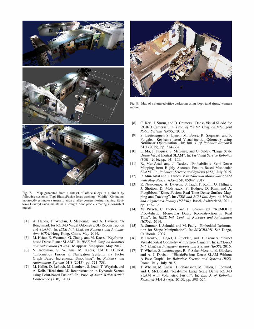
Fig. 7. Map generated from a dataset of office alleys in a circuit byfollowing systems: (Top) ElasticFusion loses tracking. (Middle) Kintinuousincorrectly estimates camera rotation at alley corners, losing tracking. (Bot-tom) GravityFusion maintains a straight floor profile creating a consistentmodel.
[4] A. Handa, T. Whelan, J. McDonald, and A. Davison. “ABenchmark for RGB-D Visual Odometry, 3D Reconstructionand SLAM”. In: IEEE Intl. Conf. on Robotics and Automa-tion, ICRA. Hong Kong, China, May 2014.
[5] M. Hsiao, E. Westman, G. Zhang, and M. Kaess. “Keyframe-based Dense Planar SLAM”. In: IEEE Intl. Conf. on Roboticsand Automation (ICRA). To appear. Singapore, May 2017.
[6] V. Indelman, S. Wiliams, M. Kaess, and F. Dellaert.“Information Fusion in Navigation Systems via FactorGraph Based Incremental Smoothing”. In: Robotics andAutonomous Systems 61.8 (2013), pp. 721–738.
[7] M. Keller, D. Lefloch, M. Lambers, S. Izadi, T. Weyrich, andA. Kolb. “Real-time 3D Reconstruction in Dynamic Scenesusing Point-based Fusion”. In: Proc. of Joint 3DIM/3DPVTConference (3DV). 2013.
Fig. 8. Map of a cluttered office deskroom using loopy (and zigzag) cameramotion.
[8] C. Kerl, J. Sturm, and D. Cremers. “Dense Visual SLAM forRGB-D Cameras”. In: Proc. of the Int. Conf. on IntelligentRobot Systems (IROS). 2013.
[9] S. Leutenegger, S. Lynen, M. Bosse, R. Siegwart, and P.Furgale. “Keyframe-based Visual-inertial Odometry usingNonlinear Optimization”. In: Intl. J. of Robotics Research34.3 (2015), pp. 314–334.
[10] L. Ma, J. Falquez, S. McGuire, and G. Sibley. “Large ScaleDense Visual Inertial SLAM”. In: Field and Service Robotics(FSR). 2016, pp. 141–155.
[11] R. Mur-Artal and J. Tardos. “Probabilistic Semi-DenseMapping from Highly Accurate Feature-Based MonocularSLAM”. In: Robotics: Science and Systems (RSS). July 2015.
[12] R. Mur-Artal and J. Tardos. Visual-Inertial Monocular SLAMwith Map Reuse. arXiv:1610.05949. 2017.
[13] R. Newcombe, A. Davison, S. Izadi, P. Kohli, O. Hilliges,J. Shotton, D. Molyneaux, S. Hodges, D. Kim, and A.Fitzgibbon. “KinectFusion: Real-Time Dense Surface Map-ping and Tracking”. In: IEEE and ACM Intl. Sym. on Mixedand Augmented Reality (ISMAR). Basel, Switzerland, 2011,pp. 127–136.
[14] M. Pizzoli, C. Forster, and D. Scaramuzza. “REMODE:Probabilistic, Monocular Dense Reconstruction in RealTime”. In: IEEE Intl. Conf. on Robotics and Automation(ICRA). 2014.
[15] R. Sumner, J. Schmid, and M. Pauly. “Embedded Deforma-tion for Shape Manipulation”. In: SIGGRAPH. San Diego,California, 2007.
[16] V. Usenko, J. Engel, J. Stuckler, and D. Cremers. “DirectVisual-Inertial Odometry with Stereo Camera”. In: IEEE/RSJIntl. Conf. on Intelligent Robots and Systems (IROS). 2016.
[17] T. Whelan, S. Leutenegger, R. F. Salas-Moreno, B. Glocker,and A. J. Davison. “ElasticFusion: Dense SLAM WithoutA Pose Graph”. In: Robotics: Science and Systems (RSS).Rome, Italy, July 2015.
[18] T. Whelan, M. Kaess, H. Johannsson, M. Fallon, J. Leonard,and J. McDonald. “Real-time Large Scale Dense RGB-DSLAM with Volumetric Fusion”. In: Intl. J. of RoboticsResearch 34.4-5 (Apr. 2015), pp. 598–626.