grease oil oil / sediment sand...retained in the wade separator. there is no straight in-and-out...
TRANSCRIPT

INTERCEPTORS
1 Wade Drains ‐ 11910 CR492, Tyler, TX, 75706 ‐ Phone: 800‐638‐9537 Fax: 888‐879‐9233 ‐ www.wadedrains.com 3‐29‐17
SELECTION GUIDE
There are five main types of interceptors: grease, oil, lint, sand and solids. Each of them requires different considerations for sizing, operation and maintenance. The information provided will help the specifier select the correct interceptor for the application. A detailed explanation of the major components and features of each type of interceptor is also provided.
Construction / Operation
Many of Wade’s grease, oil and solids interceptors are manufactured with 10 gage hot rolled steel which is welded together and coated with a high build aliphatic hybrid – trade named ArmorClad. It is an industrial abrasion - chemical - impact - moisture—UV resistant sanitary finish engineered for use on critical surfaces in harsh environments. A two component no-voc formulation delivers optimal performance in very cold or hot climates. ArmorClad is dielectric (non-conductive) so there is no potential reaction with the earth’s elements. Because of its’s dielectric properties, performance is exceptional in all forms of corrosive elements that may be present in underground environments. Because it is non-sacrificial, the finish insulates metallic products from corrosive elements including salt spray. A 100% solids characteristic helps to ensure a complete barrier is formed for protection. The aliphatic hybrid content of ArmorClad provides UV resistance well beyond what aromatic coatings can offer. Accelerated UV Aging test over extended time are ongoing to qualify the significant improvements. Typically furnished in gray.
The cover sealing gasket is manufactured with low durometer closed-cell neoprene with self-adhesive backing. The gasket is custom fitted to the interceptor body top rim ledge where it is an integral part of the body. Because of the gasket's thickness and density, it provides an ideal sealing environment for the lid. All of Wade’s interceptors are supplied with the same gasket. Dependent upon type, many interceptors are supplied with a baffle system engineered to improve the separation process. The baffle system is strategically located to direct inflow for maximum efficiency of the interceptor. Flow entering the interceptor is directed to the bottom by the baffle to avoid any disturbance of the previously accumulated surface layer of grease or oil in the device. The baffle also serves to reduce the velocity and surge of inflow, providing sufficient retention time for effective separation of the grease. The grease or oil rises to the sur-face for manual or draw-off removal and the baffle is easy to remove for cleaning. The waste water is now relieved of over 90% of the fats, oils and greases and continues to flow through the interceptor into the drainage system.
GREASE OIL OIL / SEDIMENT
SOLIDS HAIR LINT
SAND
FUR
INTERCEPTORS
2 Wade Drains ‐ 11910 CR492, Tyler, TX, 75706 ‐ Phone: 800‐638‐9537 Fax: 888‐879‐9233 ‐ www.wadedrains.com 3‐29‐17
SELECTION GUIDE
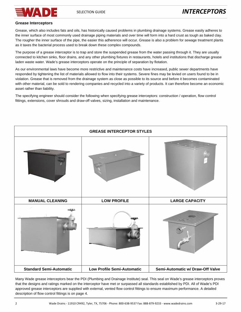
MANUAL CLEANING LOW PROFILE LARGE CAPACITY
Standard Semi-Automatic Low Profile Semi-Automatic Semi-Automatic w/ Draw-Off Valve
GREASE INTERCEPTOR STYLES
Many Wade grease interceptors bear the PDI (Plumbing and Drainage Institute) seal. This seal on Wade’s grease interceptors proves that the designs and ratings marked on the interceptor have met or surpassed all standards established by PDI. All of Wade’s PDI approved grease interceptors are supplied with external, vented flow control fittings to ensure maximum performance. A detailed description of flow control fittings is on page 4.
Grease Interceptors
Grease, which also includes fats and oils, has historically caused problems in plumbing drainage systems. Grease easily adheres to the inner surface of most commonly used drainage piping materials and over time will form into a hard crust as tough as baked clay. The rougher the inner surface of the pipe, the easier this adherence will occur. Grease is also a problem for sewage treatment plants as it taxes the bacterial process used to break down these complex compounds.
The purpose of a grease interceptor is to trap and store the suspended grease from the water passing through it. They are usually connected to kitchen sinks, floor drains, and any other plumbing fixtures in restaurants, hotels and institutions that discharge grease laden waste water. Wade’s grease interceptors operate on the principle of separation by flotation.
As our environmental laws have become more restrictive and maintenance costs have increased, public sewer departments have responded by tightening the list of materials allowed to flow into their systems. Severe fines may be levied on users found to be in violation. Grease that is removed from the drainage system as close as possible to its source and before it becomes contaminated with other material, can be sold to rendering companies and recycled into a variety of products. It can therefore become an economic asset rather than liability.
The specifying engineer should consider the following when specifying grease interceptors: construction / operation, flow control fittings, extensions, cover shrouds and draw-off valves, sizing, installation and maintenance.
INTERCEPTORS
3 Wade Drains ‐ 11910 CR492, Tyler, TX, 75706 ‐ Phone: 800‐638‐9537 Fax: 888‐879‐9233 ‐ www.wadedrains.com 3‐29‐17
SELECTION GUIDE
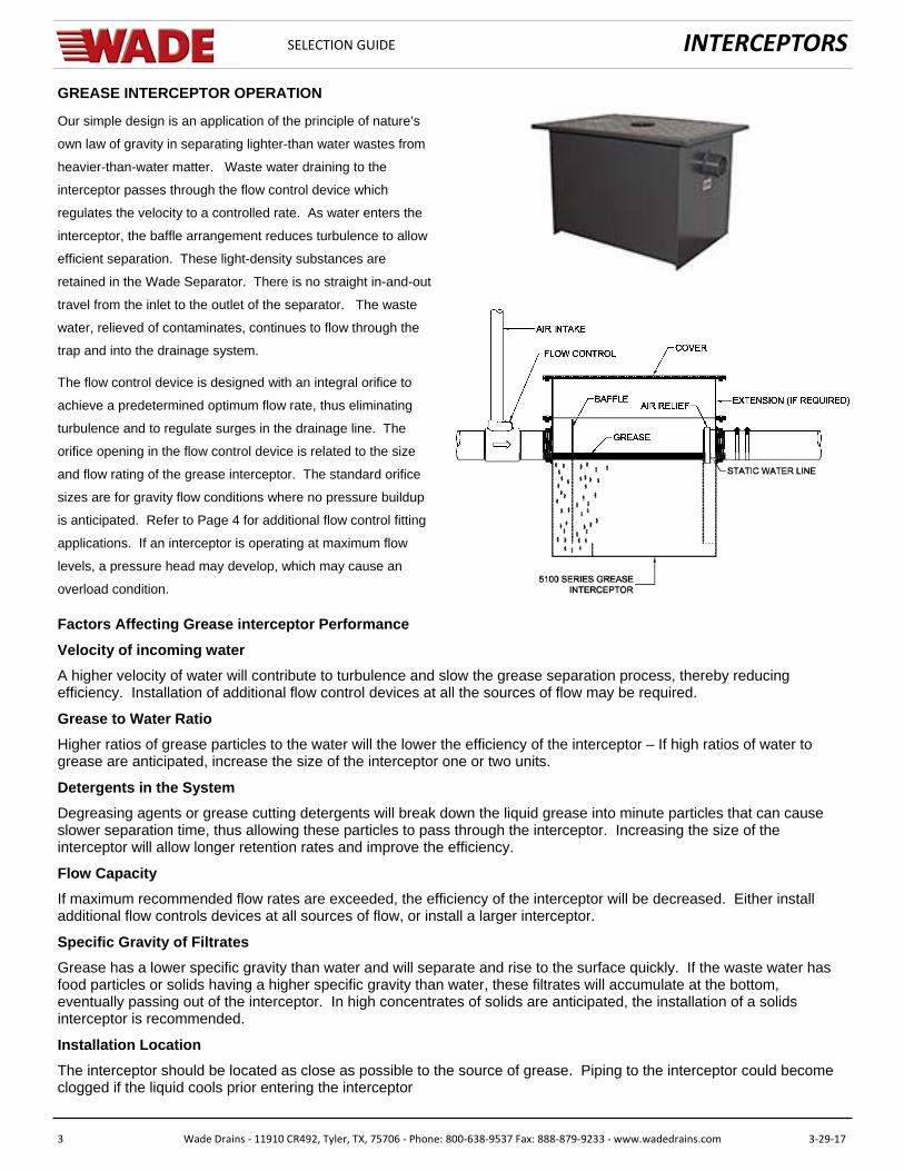
GREASE INTERCEPTOR OPERATION
Our simple design is an application of the principle of nature’s
own law of gravity in separating lighter-than water wastes from
heavier-than-water matter. Waste water draining to the
interceptor passes through the flow control device which
regulates the velocity to a controlled rate. As water enters the
interceptor, the baffle arrangement reduces turbulence to allow
efficient separation. These light-density substances are
retained in the Wade Separator. There is no straight in-and-out
travel from the inlet to the outlet of the separator. The waste
water, relieved of contaminates, continues to flow through the
trap and into the drainage system.
The flow control device is designed with an integral orifice to
achieve a predetermined optimum flow rate, thus eliminating
turbulence and to regulate surges in the drainage line. The
orifice opening in the flow control device is related to the size
and flow rating of the grease interceptor. The standard orifice
sizes are for gravity flow conditions where no pressure buildup
is anticipated. Refer to Page 4 for additional flow control fitting
applications. If an interceptor is operating at maximum flow
levels, a pressure head may develop, which may cause an
overload condition.
Factors Affecting Grease interceptor Performance
Velocity of incoming water
A higher velocity of water will contribute to turbulence and slow the grease separation process, thereby reducing efficiency. Installation of additional flow control devices at all the sources of flow may be required.
Grease to Water Ratio
Higher ratios of grease particles to the water will the lower the efficiency of the interceptor – If high ratios of water to grease are anticipated, increase the size of the interceptor one or two units.
Detergents in the System
Degreasing agents or grease cutting detergents will break down the liquid grease into minute particles that can cause slower separation time, thus allowing these particles to pass through the interceptor. Increasing the size of the interceptor will allow longer retention rates and improve the efficiency.
Flow Capacity
If maximum recommended flow rates are exceeded, the efficiency of the interceptor will be decreased. Either install additional flow controls devices at all sources of flow, or install a larger interceptor.
Specific Gravity of Filtrates
Grease has a lower specific gravity than water and will separate and rise to the surface quickly. If the waste water has food particles or solids having a higher specific gravity than water, these filtrates will accumulate at the bottom, eventually passing out of the interceptor. In high concentrates of solids are anticipated, the installation of a solids interceptor is recommended.
Installation Location
The interceptor should be located as close as possible to the source of grease. Piping to the interceptor could become clogged if the liquid cools prior entering the interceptor
INTERCEPTORS
4 Wade Drains ‐ 11910 CR492, Tyler, TX, 75706 ‐ Phone: 800‐638‐9537 Fax: 888‐879‐9233 ‐ www.wadedrains.com 3‐29‐17
SELECTION GUIDE
Interceptor Selection Guide
FLOW CONTROL FITTING APPLICATION:
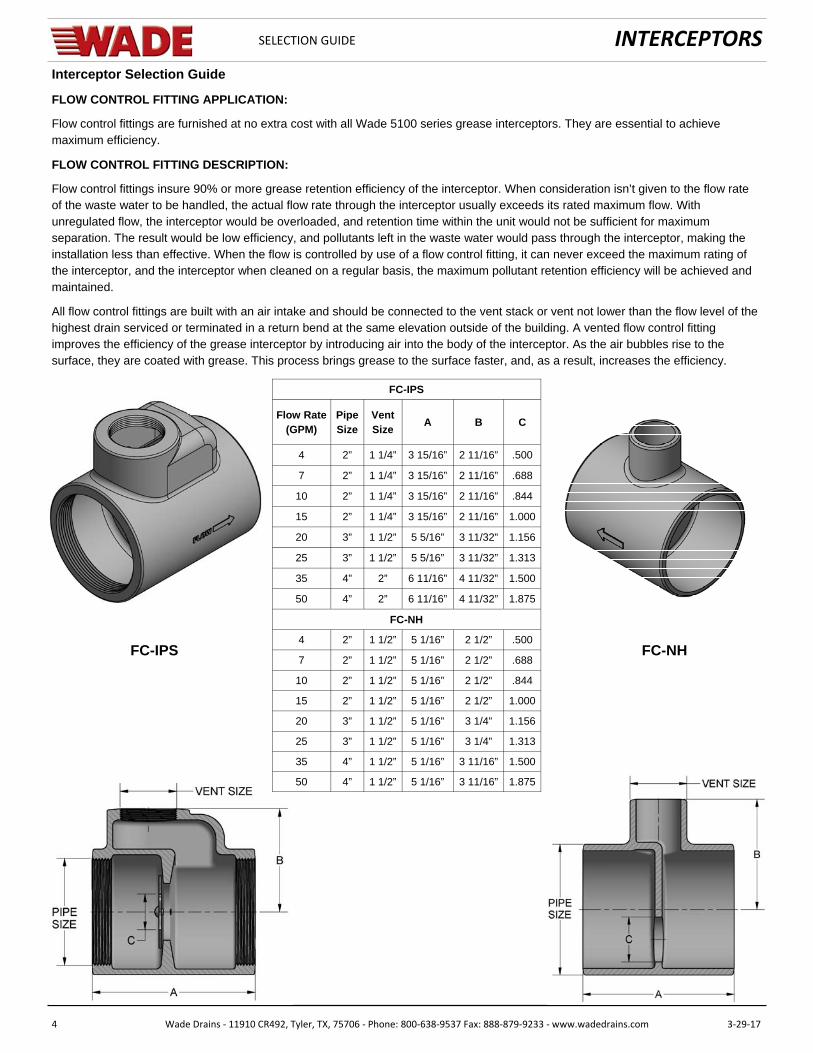
Flow control fittings are furnished at no extra cost with all Wade 5100 series grease interceptors. They are essential to achieve maximum efficiency.
FLOW CONTROL FITTING DESCRIPTION:
Flow control fittings insure 90% or more grease retention efficiency of the interceptor. When consideration isn’t given to the flow rate of the waste water to be handled, the actual flow rate through the interceptor usually exceeds its rated maximum flow. With unregulated flow, the interceptor would be overloaded, and retention time within the unit would not be sufficient for maximum separation. The result would be low efficiency, and pollutants left in the waste water would pass through the interceptor, making the installation less than effective. When the flow is controlled by use of a flow control fitting, it can never exceed the maximum rating of the interceptor, and the interceptor when cleaned on a regular basis, the maximum pollutant retention efficiency will be achieved and maintained.
All flow control fittings are built with an air intake and should be connected to the vent stack or vent not lower than the flow level of the highest drain serviced or terminated in a return bend at the same elevation outside of the building. A vented flow control fitting improves the efficiency of the grease interceptor by introducing air into the body of the interceptor. As the air bubbles rise to the surface, they are coated with grease. This process brings grease to the surface faster, and, as a result, increases the efficiency.
FC-IPS FC-NH
Flow Rate (GPM)
Pipe Size
Vent Size
A B C
4 2” 1 1/4” 3 15/16” 2 11/16” .500
7 2” 1 1/4” 3 15/16” 2 11/16” .688
10 2” 1 1/4” 3 15/16” 2 11/16” .844
15 2” 1 1/4” 3 15/16” 2 11/16” 1.000
20 3” 1 1/2” 5 5/16” 3 11/32” 1.156
25 3” 1 1/2” 5 5/16” 3 11/32” 1.313
35 4” 2” 6 11/16” 4 11/32” 1.500
50 4” 2” 6 11/16” 4 11/32” 1.875
FC-NH
4 2” 1 1/2” 5 1/16” 2 1/2” .500
7 2” 1 1/2” 5 1/16” 2 1/2” .688
10 2” 1 1/2” 5 1/16” 2 1/2” .844
15 2” 1 1/2” 5 1/16” 2 1/2” 1.000
20 3” 1 1/2” 5 1/16” 3 1/4” 1.156
25 3” 1 1/2” 5 1/16” 3 1/4” 1.313
35 4” 1 1/2” 5 1/16” 3 11/16” 1.500
50 4” 1 1/2” 5 1/16” 3 11/16” 1.875
FC-IPS

INTERCEPTORS
5 Wade Drains ‐ 11910 CR492, Tyler, TX, 75706 ‐ Phone: 800‐638‐9537 Fax: 888‐879‐9233 ‐ www.wadedrains.com 3‐29‐17
SELECTION GUIDE
EXTENSIONS (Bolt-On & Integral)
Extensions should be specified on grease and oil interceptors when the interceptor is buried in the ground, vertical adjustment of the interceptor is necessary to meet the drainage piping, and/or floor level access requirements. Extension heights range from four inches to any maximum practical for serviceability. Extensions in excess of 20" are not recommended. One must consider the slope of the drainage piping from the fixtures to the inlet of the interceptor. Typically, allow a slope of ¼" per foot in the drainage pipe. Therefore, there will be many installations, especially with large interceptors, where the sloped drainage pipe ends up below the inlet connection. An extension is added to the top of the interceptor so that the inlet can be lowered to meet the incoming drainage pipe and the lid of the interceptor can be extended to floor level.
Wade offers three different kinds of extensions: integral, bolt on and cover shrouds. An integral extension is specified by expanding the "H" dimension on the interceptor. The "H" dimension is from the center of the inlet and outlet to the top of the interceptor. One would specify a "H" dimension to meet the job requirements and the interceptor will be manufactured to that specification. The extension is incorporated into the production of the interceptor to produce a seamless, integral interceptor.
A second method of providing an extension is a bolt on design. In this example, a top is manufactured out of the same material as the body. The extension is secured to the body by means of bolts bearing against its base flange, compressing the sealing gasket to complete the union. The regular lid is bolted to the extension top in the same manner as it would be to the body of a standard interceptor.
EXTENSIONS (Adjustable)
In installations where the exact extension dimension required is unknown or where little notice has been provided to the installer advising of the need for an extension; integral and bolt on extensions are impractical due to the time necessary for their fabrication. Wade’s nationwide network of manufacturer's representatives stock adjustable extensions for immediate shipment to jobsites when these situations occur. The extension is adjust-able and is secured to the interceptor similar to a fixed extension. After bolting the extension to the interceptor, the top is adjustable to grade.
SHROUDS
Cover shrouds incorporate either standard or draw-off grease interceptors mounted on adjustable elevation cradles in either open or closed bottom housings with non-skid floor level lids. The cover shroud is adjustable and is recessed into the slab to house the interceptor. Cover shrouds are particularly important where below floor level installation of draw-off grease interceptors is required, because such models cannot be installed independently with tops at the finished floor level.
INTERCEPTORS
6 Wade Drains ‐ 11910 CR492, Tyler, TX, 75706 ‐ Phone: 800‐638‐9537 Fax: 888‐879‐9233 ‐ www.wadedrains.com 3‐29‐17
SELECTION GUIDE
GREASE INTERCEPTOR SIZING
Reliable performance of any grease interceptor is dependent on its being correctly sized to handle the anticipated drainage load from the fixtures it serves. Each Wade interceptor is flow and capacity rated for easy selection when sizing requirements have been established and met. Sizing is based on fixture drainage period, service required and volume of wastewater to be handled. These factors combine to establish the anticipated flow rate and the size of the interceptor required. The flow control fitting that is provided with every Wade grease interceptor sized 50 GPM and smaller, is installed in the fixture drain line ahead of the interceptor and controls the flow of drainage to the interceptor's rated capacity. This is especially important when the drainage load exceeds that for which the interceptor is sized to handle.
The following sizing formula is based on the P.D.I. G-101 (Plumbing and Drainage Institute) requirements:
1. Calculate the volume in cubic inches of all the fixtures to be served by the Grease Interceptor.
(length x width x depth = capacity)
1. Determine the capacity in gallons.
2. Determine the flow rate and drainage period.
3. Select the appropriate size interceptor.
4. The flow control fitting, supplied with the interceptor, must be in position at all times. If this is removed, or not provided, the inter-ceptor will not function to P.D.I. standards.
5. If an interceptor is to be installed with the top level at the finished floor, an extension type may be required. In that instance, the “H” dimension is required, (center line of inlet/outlet to top of the finished floor) and must be specified at time of ordering.
Refer to Page 7 for Sizing Example.
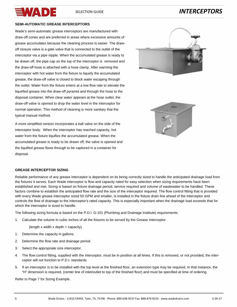
SEMI-AUTOMATIC GREASE INTERCEPTORS
Wade’s semi-automatic grease interceptors are manufactured with
draw-off cones and are preferred in areas where excessive amounts of
grease accumulates because the cleaning process is easier. The draw-
off closure valve is a gate valve that is connected to the outlet of the
interceptor via a pipe nipple. When the accumulated grease is ready to
be drawn off, the pipe cap on the top of the interceptor is removed and
the draw-off hose is attached with a hose clamp. After warming the
interceptor with hot water from the fixture to liquefy the accumulated
grease, the draw-off valve is closed to block water escaping through
the outlet. Water from the fixture enters at a low flow rate to elevate the
liquefied grease into the draw-off pyramid and through the hose to the
disposal container. When clear water appears at the hose outlet, the
draw-off valve is opened to drop the water level in the interceptor for
normal operation. This method of cleaning is more sanitary that the
typical manual method.
A more simplified version incorporates a ball valve on the side of the
interceptor body. When the interceptor has reached capacity, hot
water from the fixture liquifies the accumulated grease. When the
accumulated grease is ready to be drawn off, the valve is opened and
the liquified grease flows through to be captured in a container for
disposal.

INTERCEPTORS
7 Wade Drains ‐ 11910 CR492, Tyler, TX, 75706 ‐ Phone: 800‐638‐9537 Fax: 888‐879‐9233 ‐ www.wadedrains.com 3‐29‐17
SELECTION GUIDE
Flow Rate (GPM) 4 7 10 15 20 25 35 50
Capacity (LBS) 8 14 20 30 40 50 70 100
Procedure
The following example shows the steps for properly sizing a grease interceptor to suit requirements of specific fixtures.
Step Formula Example
1 Determine cubic content of fixture by mul plying length x
width x depth
Sink 36” x 24” x 14” deep
36x24x14 = 12,096 cubic in.
2 Determine capacity in gallons. 1 Gal = 231 cubic inches. Contents in Gallons:
12,096 ÷ 231 = 52.36 Gal
3
Determine actual drainage load. Fixtures are normally filled
to 75% of capacity plus the items being washed displace
about 25% of the fixture content, thus Actual Drainage
Load = 75% of the fixture capacity
Actual Drainage Load
52.36 Gal x 0.75 = 39.3 GPM
4
Determine flow rate and drainage period. Standard prac ce
dictates a one minute drainage period. Where condi ons
permit, a two minute period is acceptable. Drainage period
is the actual me required to completely drain the fixture.
Flow Rate = Actual Drainage Load ÷ Drainage Period.
Calculate the flow rate for
a one minute period:
39.3 ÷ 1 = 39.3 GPM
For a two minute period:
39.3 ÷ 2 = 19.65 GPM
5
Select interceptor from the Sizing & Ra ng Table (above)
which corresponds to the calculated flow rate. When the
flow rate falls between two sizes, use the larger size.
For a one minute period:
50 GPM Interceptor Required
For a two minute period:
20 GPM Interceptor Required
Alternate Sizing Method (Based on Drainage Fixture‐Units)
Fixture Outlet (Trap Size) Drainage Fixture Unit Value GPM Equivalent PDI Interceptor Size
1‐1/4” 1 7.5 10
1‐1/2” 2 15 15
2” 3 22 25
2” 4 30 35
3” 5 37.5 50
4” 6 45 50
Grease Interceptor Sizing – PDI (Plumbing & Drainage Ins tute) Method
Sizing & Ra ng
INTERCEPTORS
8 Wade Drains ‐ 11910 CR492, Tyler, TX, 75706 ‐ Phone: 800‐638‐9537 Fax: 888‐879‐9233 ‐ www.wadedrains.com 3‐29‐17
SELECTION GUIDE
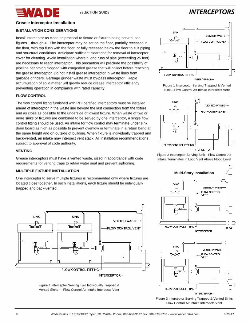
Grease Interceptor Installation
INSTALLATION CONSIDERATIONS
Install interceptor as close as practical to fixture or fixtures being served, see figures 1 through 4. The interceptor may be set on the floor, partially recessed in the floor, with top flush with the floor, or fully recessed below the floor to suit piping and structural conditions. Anticipate sufficient clearance for removal of interceptor cover for cleaning. Avoid installation wherein long runs of pipe (exceeding 25 feet) are necessary to reach interceptor. This precaution will preclude the possibility of pipeline becoming clogged with congealed grease that will collect before reaching the grease interceptor. Do not install grease interceptor in waste lines from garbage grinders. Garbage grinder waste must by-pass interceptor. Rapid accumulation of solid matter will greatly reduce grease interceptor efficiency preventing operation in compliance with rated capacity.
FLOW CONTROL
The flow control fitting furnished with PDI certified interceptors must be installed ahead of interceptor in the waste line beyond the last connection from the fixture and as close as possible to the underside of lowest fixture. When waste of two or more sinks or fixtures are combined to be served by one interceptor, a single flow control fitting should be used. Air intake for flow control may terminate under sink drain board as high as possible to prevent overflow or terminate in a return bend at the same height and on outside of building. When fixture is individually trapped and back-vented, air intake may intersect vent stack. All installation recommendations subject to approval of code authority.
VENTING
Grease interceptors must have a vented waste, sized in accordance with code requirements for venting traps to retain water seal and prevent siphoning.
MULTIPLE FIXTURE INSTALLATION
One interceptor to serve multiple fixtures is recommended only where fixtures are located close together. In such installations, each fixture should be individually trapped and back-vented.
Figure 1 Interceptor Serving Trapped & Vented Sink—Flow Control Air Intake Intersects Vent
Figure 2 Interceptor Serving Sink—Flow Control Air Intake Terminates In Loop Vent Above Flood Level
Figure 3 Interceptor Serving Trapped & Vented Sinks Flow Control Air Intake Intersects Vent
Multi-Story Installation
Figure 4 Interceptor Serving Two Individually Trapped & Vented Sinks — Flow Control Air Intake Intersects Vent
INTERCEPTORS
9 Wade Drains ‐ 11910 CR492, Tyler, TX, 75706 ‐ Phone: 800‐638‐9537 Fax: 888‐879‐9233 ‐ www.wadedrains.com 3‐29‐17
SELECTION GUIDE
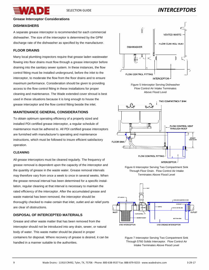
Grease Interceptor Considerations
DISHWASHERS
A separate grease interceptor is recommended for each commercial
dishwasher. The size of the interceptor is determined by the GPM
discharge rate of the dishwasher as specified by the manufacturer.
FLOOR DRAINS
Many local plumbing inspectors require that grease laden wastewater
flowing into floor drains must flow through a grease interceptor before
draining into the sanitary sewer system. In these instances, the flow
control fitting must be installed underground, before the inlet to the
interceptor, to moderate the flow from the floor drains and to ensure
maximum performance. Consideration should be given to providing
access to the flow control fitting in these installations for proper
cleaning and maintenance. The Wade extended cover shroud is best
used in these situations because it is long enough to house the
grease interceptor and the flow control fitting beside the inlet.
MAINTENANCE GENERAL CONSIDERATIONS
To obtain optimum operating efficiency of a properly sized and
installed PDI certified grease interceptor, a regular schedule of
maintenance must be adhered to. All PDI certified grease interceptors
are furnished with manufacturer’s operating and maintenance
instructions, which must be followed to insure efficient satisfactory
operation.
CLEANING
All grease interceptors must be cleaned regularly. The frequency of
grease removal is dependent upon the capacity of the interceptor and
the quantity of grease in the waste water. Grease removal intervals
may therefore vary from once a week to once in several weeks. When
the grease removal interval has been determined for a specific instal-
lation, regular cleaning at that interval is necessary to maintain the
rated efficiency of the interceptor. After the accumulated grease and
waste material has been removed, the interceptor should be
thoroughly checked to make certain that inlet, outlet and air relief ports
are clear of obstructions.
DISPOSAL OF INTERCEPTED MATERIALS
Grease and other waste matter that has been removed from the
interceptor should not be introduced into any drain, sewer, or natural
body of water. This waste matter should be placed in proper
containers for disposal. Where recovery of grease is desired, it can be
handled in a manner suitable to the authorities.
Figure 5 Interceptor Serving Dishwasher Flow Control Air Intake Terminates
Above Flood Level
Figure 6 Interceptor Serving Two Compartment Sink Through Floor Drain. Flow Control Air Intake
Terminates Above Flood Level
Figure 7 Interceptor Serving Two Compartment Sink Through 5760 Solids Interceptor. Flow Control Air
Intake Terminates Above Flood Level
INTERCEPTORS
10 Wade Drains ‐ 11910 CR492, Tyler, TX, 75706 ‐ Phone: 800‐638‐9537 Fax: 888‐879‐9233 ‐ www.wadedrains.com 3‐29‐17
SELECTION GUIDE
OIL INTERCEPTORS
PURPOSE
Wade oil interceptors have been used in plumbing waste systems to help protect property and the environment against explosion, fire, and pollution for many decades.
PRINCIPLES
Wade oil interceptors are designed similar to the grease interceptors. Both are designed on the principle that oils are lighter than water and thus gravity causes the oil to rise to the surface of the water. Wade oil interceptors come equipped with a combination pressure equalizing / flow diffusing baffle and with an optional sediment bucket on the inlet to trap stones, grit and other substances. Their solid flow-diffusing baffle eliminates turbulence and allows for high efficiency of separation.
OPERATION
As waste water draining to the interceptor passes through the inlet at a controlled rate. As water enters the interceptor, the baffle arrangement reduces turbulence to allow efficient separation. The oil, as separation occurs, floats to the top and is accumulated.
The waste water, relieved of contaminates, continues to flow through the trap and into the drainage system. Solids and sludge carried in the water are stopped by the baffle and collected in the solids retaining bucket between the inlet and the flow-retarding baffle. Maximum separation and interception is affected in proportion to the elimination of turbulence of wastewater within the interceptor. The unique Wade baffle/bucket design permits almost 90 percent of the interior of the interceptor to be used for the function of oil separation.
INTERMITTENT FLOW
The maximum amount of waste water containing non-soluble oil that can be discharged through any listed separator is two (2) times the stated flow rate in gallons per minute (g.p.m.). For example, a separator rated at 50 g.p.m. may only have 100 gallons discharged through it in a one-hour time period. This is usually accomplished by a batch dumping process. However, 100 gallons may be discharged continuously if the flow rate is monitored at the rate of 1.66 g.p.m.
INSTALLATION
Install the interceptor as close as practical to the source(s) being served. Avoid installations where long runs of pipe (exceeding 25’) are necessary to reach the interceptor. This precaution will preclude the possibility of oil and sludge becoming congealed in the pipe before it reaches the interceptor.
The unit may be placed on the floor, partially recessed in the floor, recessed with the top flush with the floor or encased below the floor in an appropriate housing to accommodate piping and structural considerations. Whatever the installation method, anticipate sufficient clearance to remove the cover and baffles for cleaning. Verify that no obstructions will be placed over the interceptor after installation. A minimum clearance equal the overall height of the interceptor (excluding any extension) is recommended.
Waste with heavy accumulations of sand or solids must bypass the interceptor because the rapid accumulation of solid matter will significantly reduce the rated efficiency of the interceptor. In an application where solids will be present, a solids interceptor should be used.
Placement of a interceptor in a high traffic area is an important concern. If the unit is to be installed flush with the floor, it is necessary to load rate the interceptor cover. The standard Wade interceptor is designed for pedestrian and light traffic only. If heavy loads are anticipated, the interceptor must be specified with an appropriate reinforced cover.
An extension is frequently used to increase the rough-in dimension from the inlet/outlet centerline to the finished floor. The extension anchor flange is not adequate to support the entire interceptor. For installations at flush-with-floor level, the interceptor chamber must rest on solid ground or a concrete pad. For upper floor installations, (suspended above the lower floor ceiling), the interceptor must be independently supported on hangers suitable to carry the entire weight.
A single interceptor serving multiple fixtures or wash down areas is recommended only where the sources are located close together. In these installations, each drain should be individually trapped and vented.
INTERCEPTORS
11 Wade Drains ‐ 11910 CR492, Tyler, TX, 75706 ‐ Phone: 800‐638‐9537 Fax: 888‐879‐9233 ‐ www.wadedrains.com 3‐29‐17
SELECTION GUIDE
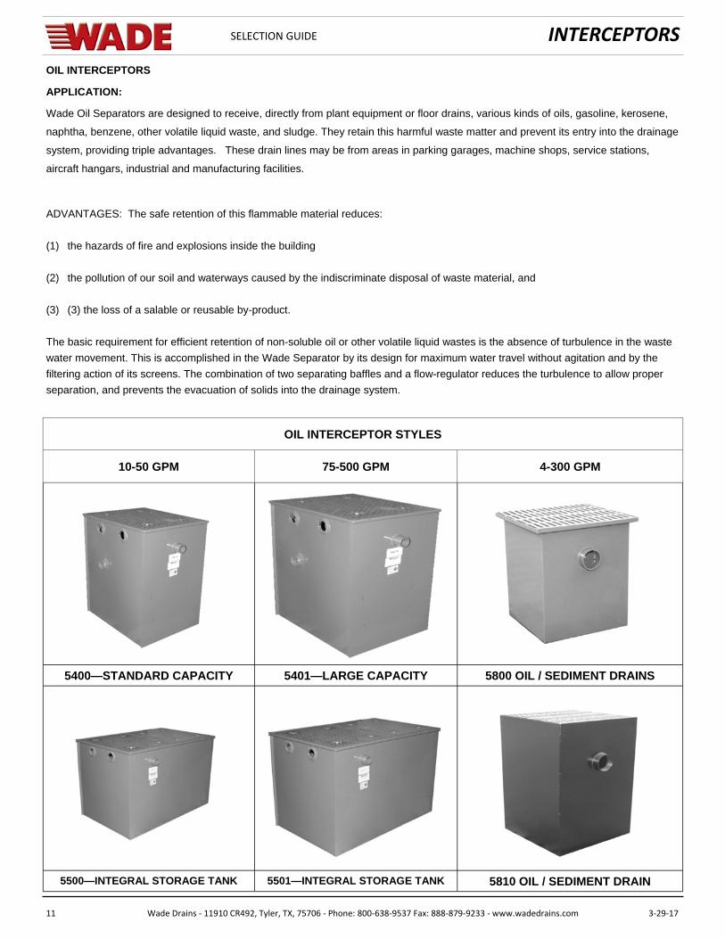
OIL INTERCEPTORS
APPLICATION:
Wade Oil Separators are designed to receive, directly from plant equipment or floor drains, various kinds of oils, gasoline, kerosene,
naphtha, benzene, other volatile liquid waste, and sludge. They retain this harmful waste matter and prevent its entry into the drainage
system, providing triple advantages. These drain lines may be from areas in parking garages, machine shops, service stations,
aircraft hangars, industrial and manufacturing facilities.
ADVANTAGES: The safe retention of this flammable material reduces:
(1) the hazards of fire and explosions inside the building
(2) the pollution of our soil and waterways caused by the indiscriminate disposal of waste material, and
(3) (3) the loss of a salable or reusable by-product.
The basic requirement for efficient retention of non-soluble oil or other volatile liquid wastes is the absence of turbulence in the waste
water movement. This is accomplished in the Wade Separator by its design for maximum water travel without agitation and by the
filtering action of its screens. The combination of two separating baffles and a flow-regulator reduces the turbulence to allow proper
separation, and prevents the evacuation of solids into the drainage system.
5400—STANDARD CAPACITY 5401—LARGE CAPACITY 5800 OIL / SEDIMENT DRAINS
5500—INTEGRAL STORAGE TANK 5501—INTEGRAL STORAGE TANK 5810 OIL / SEDIMENT DRAIN
10-50 GPM
OIL INTERCEPTOR STYLES
75-500 GPM 4-300 GPM

INTERCEPTORS
12 Wade Drains ‐ 11910 CR492, Tyler, TX, 75706 ‐ Phone: 800‐638‐9537 Fax: 888‐879‐9233 ‐ www.wadedrains.com 3‐29‐17
SELECTION GUIDE
OIL INTERCEPTORS
CONSTRUCTION
Wade oil separators are built of all-welded steel plate for maximum strength and durability. Both the interior and exterior are coated to resist acid corrosion. These units have removable covers for on-the-floor, partially recessed or flush-with-floor installation, suitable for pedestrian traffic or reinforced covers for heavy traffic. The cover is secured to the body with recessed bolts and includes an extra-heavy leakproof gasket. Separating screens and a flow-regulator filter screen regulate flow and filter waste water, making outside flow control or retarder unnecessary. An extra-large inlet compartment has adjustable oil draw-off. Independent internal vent connection on the inlet compartment dissipates excessive fumes and vapors from evaporating gases and volatile liquids. The outlet of the separator is vented to prevent siphoning of its contents into the drainage system.
All units are available in double-wall construction with leak detection if specified.
DESIGN:
Wade oil interceptors are designed to protect against water pollution by preventing oils and sediment in waste water from entering drain lines. The design allows intercepted oils to be drawn-off automatically for storage continuously during operation. Sediment should be removed from the interceptor at regular intervals.
SIZING:
1. Determine maximum volume of waste water in G.P.M. or L.P.M., by summing volumes of all discharging fixtures that may enter the drain lines at one time.
2. Select oil interceptor with flow rating equal to peak volume in G.P.M. or L.P.M. (see table on shop drawing.) Provide storage tank capable of handling the volume.
5501 Illustrated
INTERCEPTORS
13 Wade Drains ‐ 11910 CR492, Tyler, TX, 75706 ‐ Phone: 800‐638‐9537 Fax: 888‐879‐9233 ‐ www.wadedrains.com 3‐29‐17
SELECTION GUIDE
OIL INTERCEPTORS
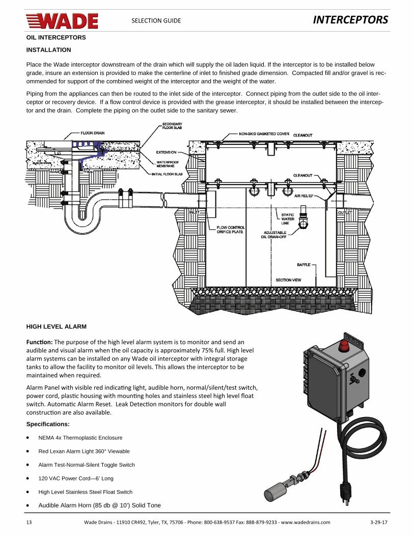
INSTALLATION
Place the Wade interceptor downstream of the drain which will supply the oil laden liquid. If the interceptor is to be installed below grade, insure an extension is provided to make the centerline of inlet to finished grade dimension. Compacted fill and/or gravel is rec-ommended for support of the combined weight of the interceptor and the weight of the water.
Piping from the appliances can then be routed to the inlet side of the interceptor. Connect piping from the outlet side to the oil inter-ceptor or recovery device. If a flow control device is provided with the grease interceptor, it should be installed between the intercep-tor and the drain. Complete the piping on the outlet side to the sanitary sewer.
HIGH LEVEL ALARM
Func on: The purpose of the high level alarm system is to monitor and send an audible and visual alarm when the oil capacity is approximately 75% full. High level alarm systems can be installed on any Wade oil interceptor with integral storage tanks to allow the facility to monitor oil levels. This allows the interceptor to be maintained when required.
Alarm Panel with visible red indica ng light, audible horn, normal/silent/test switch, power cord, plas c housing with moun ng holes and stainless steel high level float switch. Automa c Alarm Reset. Leak Detec on monitors for double wall construc on are also available.
Specifications:
NEMA 4x Thermoplastic Enclosure
Red Lexan Alarm Light 360° Viewable
Alarm Test-Normal-Silent Toggle Switch
120 VAC Power Cord—6’ Long
High Level Stainless Steel Float Switch
Audible Alarm Horn (85 db @ 10’) Solid Tone
INTERCEPTORS
14 Wade Drains ‐ 11910 CR492, Tyler, TX, 75706 ‐ Phone: 800‐638‐9537 Fax: 888‐879‐9233 ‐ www.wadedrains.com 3‐29‐17
SELECTION GUIDE
OIL INTERCEPTORS
Recommended Installations
• Commercial Uses Industrial Uses • Filling and Service Stations Machine Shops • Maintenance Garages Refineries
• Airport Hangars • Fabrication and Welding Plants • Laundries and Cleaning Establishments • Parking Facilities
FLOW CONTROL
The interceptor is designed to achieve a predetermined optimum flow rate, thus eliminating turbulence and to regulate surges in the drainage line. The Wade flow control must be installed properly in every installation. An oil interceptor correctly designed to separate oil and light density substances from wastewater, will not by itself govern or regulate the flow of water through it at all times to sufficiently assure the flotation separation of the entrained substances which are to be intercepted at maximum efficiency.
The flow control device, designed with an integral orifice, gives a pre-determined optimum flow rate and thus assures the elimination of turbulence in the oil interceptor, which could otherwise occur from sudden surges through the drainage line.
The orifice openings are related to the size and gallons per minute rating of the oil interceptor. It should also be noted that standard orifice sizing is for gravity flow conditions where no pressure build-up is considered. If an interceptor is operating at maximum flow levels, a head may develop, in which case overload conditions may still exist.
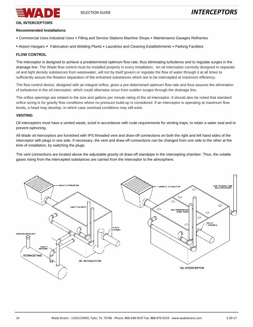
VENTING
Oil interceptors must have a vented waste, sized in accordance with code requirements for venting traps, to retain a water seal and to prevent siphoning.
All Wade oil interceptors are furnished with IPS threaded vent and draw-off connections on both the right and left hand sides of the interceptor with plugs in one side. If necessary, the vent and draw-off connections can be changed from one side to the other at the time of installation, by switching the plugs.
The vent connections are located above the adjustable gravity oil draw-off standpipe in the intercepting chamber. Thus, the volatile gases rising from the intercepted substances are carried from the interceptor to the atmosphere.
INTERCEPTORS
15 Wade Drains ‐ 11910 CR492, Tyler, TX, 75706 ‐ Phone: 800‐638‐9537 Fax: 888‐879‐9233 ‐ www.wadedrains.com 3‐29‐17
SELECTION GUIDE
TYPICAL CODE REGULATIONS
Vehicle servicing. When an oil interceptor is installed in an automobile, truck, bus, or tractor garage or in a service station or repair shop with facilities for motor or transmission overhauling, it must have a minimum static water depth of 24 inches (600) below the in-vert of the interceptor outlet and a minimum static water capacity of 6 cubic feet. This regulation applies to facilities where not more than three vehicles are serviced. For each additional vehicle up to and including ten, 1 cubic foot of static capacity shall be added. For each vehicle over ten, an additional 0.25 cubic foot shall be added. Vehicle storage and servicing. Where motor vehicles are serviced and stored, an oil interceptor shall be installed with a static water capacity of 1 cubic foot for every 100 square feet of area to be drained. The oil interceptor shall have a minimum static water level of 6 cubic feet.
Mechanical car washing. In facilities designed especially for mechanical washing of motor vehicles, a sand and gravel interceptor shall be installed to receive the waste water from all washing facilities. A minimum static water level of 2.5 feet and a minimum static water capacity of 50 cubic feet shall be maintained. Where motor cleaning services are rendered at mechanical car washing facilities, an oil interceptor shall be installed in that section of the drainage system which receives waste water from this operation.
Vehicle storage. In motor vehicle storage facilities, a combination interceptor-drain shall be installed with a static water level of 1 gal-lon for every 100 square feet of area to be drained. Manual car washing. In a one-car washing facility, a combination interceptor-drain shall be installed with a minimum static water capacity of 30 gallons.
OIL INTERCEPTORS
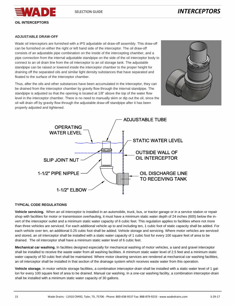
ADJUSTABLE DRAW-OFF
Wade oil interceptors are furnished with a IPS adjustable oil draw-off assembly. This draw-off can be furnished on either the right or left hand side of the interceptor. The oil draw-off consists of an adjustable pipe combination on the inside of the intercepting chamber, and a pipe connection from the internal adjustable standpipe on the side of the oil interceptor body to connect to an oil drain line from the oil interceptor to an oil storage tank. The adjustable standpipe can be raised or lowered inside the interceptor chamber to the proper height for draining off the separated oils and similar light density substances that have separated and floated to the surface of the interceptor chamber.
Thus, after the oils and other substances have been accumulated in the interceptor, they can be drained from the interceptor chamber by gravity flow through the internal standpipe. The standpipe is adjusted so that the opening is located at 1/8” above the top of the water flow level in the interceptor chamber. There is no need to manually skim or dip out the oil, since the oil will drain off by gravity flow through the adjustable draw-off standpipe after it has been properly adjusted and tightened.

INTERCEPTORS
16 Wade Drains ‐ 11910 CR492, Tyler, TX, 75706 ‐ Phone: 800‐638‐9537 Fax: 888‐879‐9233 ‐ www.wadedrains.com 3‐29‐17
SELECTION GUIDE
SOLIDS INTERCEPTORS
The interception and retention of solids cannot be overlooked. Materials such as hair, grindings, ceramic waste, plaster, dental wastes, aquarium and other small gravel, jewels and precious metals are a few solids that should pass through a solids interceptor before entering the waste drain line. Deleterious solids should be intercepted to prevent clogging of the drainage lines and valuable materials require interception for retrieval.
Wade manufactures a complete line of solids interceptors designed to handle any waterborne solids. Most often these interceptors replace the standard traps of the fixtures they serve. The solids interceptor with a low inlet and high outlet becomes the fixture trap. Solids interceptors are manufactured with easily removable strainers or sediment baskets that serve to retain the intercepted solids while allowing water to flow through. It is good engineering practice to specify a solids interceptor immediately before a grease interceptor so that all debris and solid wastes are caught in the solids interceptor before they enter the grease interceptor. This will ensure that the grease interceptor is not filled as quickly with solid wastes that will only impair its efficiency. In addition, most foul odors from grease interceptors are from rotting solids, not from the grease itself. Proper separation of these solids will reduce the odor problem typically experienced with grease interceptors filled with rotting solids.
5720 TOP ACCESS 5730 BOTTOM ACCESS 5740 LARGE CAPACITY– TOP ACCESS
5741 LARGE CAPACITY—TOP ACCESS 5750 BOTTOM ACCESS—HAIR 5760 TOP ACCESS W/ LATCHES
SOLIDS INTERCEPTOR STYLES
5770 SIDE ACCESS 5790 SIDE ACCESS 5700 TOP ACCESS—FISH SCALE
INTERCEPTORS
17 Wade Drains ‐ 11910 CR492, Tyler, TX, 75706 ‐ Phone: 800‐638‐9537 Fax: 888‐879‐9233 ‐ www.wadedrains.com 3‐29‐17
SELECTION GUIDE
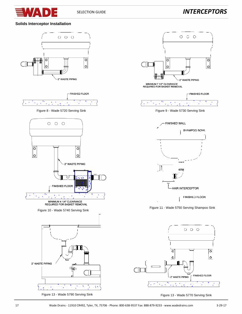
Solids Interceptor Installation
Figure 9 - Wade 5730 Serving Sink Figure 8 - Wade 5720 Serving Sink
Figure 10 - Wade 5740 Serving Sink
Figure 11 - Wade 5750 Serving Shampoo Sink
Figure 13 - Wade 5770 Serving Sink
Figure 10 - Wade 5740 Serving Sink
Figure 13 - Wade 5790 Serving Sink
INTERCEPTORS
18 Wade Drains ‐ 11910 CR492, Tyler, TX, 75706 ‐ Phone: 800‐638‐9537 Fax: 888‐879‐9233 ‐ www.wadedrains.com 3‐29‐17
SELECTION GUIDE
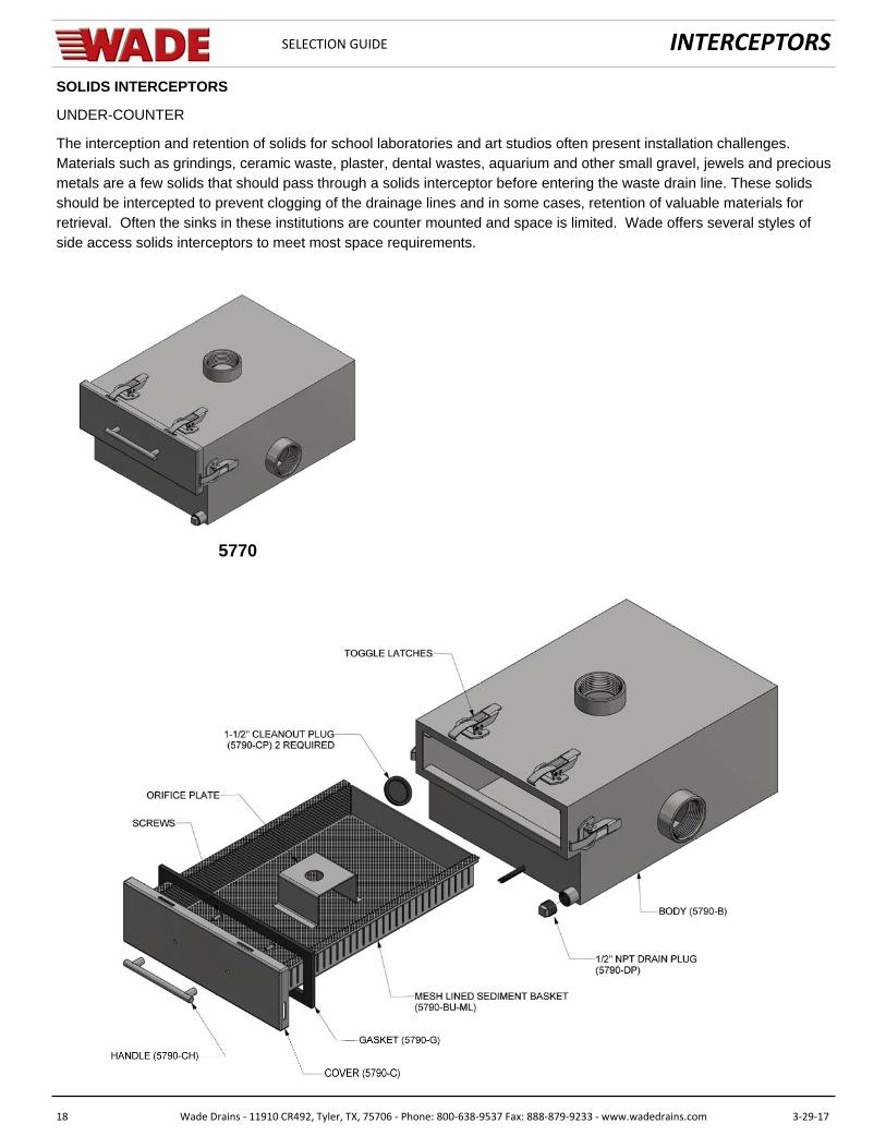
SOLIDS INTERCEPTORS
UNDER-COUNTER
The interception and retention of solids for school laboratories and art studios often present installation challenges. Materials such as grindings, ceramic waste, plaster, dental wastes, aquarium and other small gravel, jewels and precious metals are a few solids that should pass through a solids interceptor before entering the waste drain line. These solids should be intercepted to prevent clogging of the drainage lines and in some cases, retention of valuable materials for retrieval. Often the sinks in these institutions are counter mounted and space is limited. Wade offers several styles of side access solids interceptors to meet most space requirements.
5770

INTERCEPTORS
19 Wade Drains ‐ 11910 CR492, Tyler, TX, 75706 ‐ Phone: 800‐638‐9537 Fax: 888‐879‐9233 ‐ www.wadedrains.com 3‐29‐17
SELECTION GUIDE
LINT INTERCEPTORS
CONSTRUCTION
Wade lint separators are built of all-welded steel plate for maximum strength and durability. Both the interior and exterior are coated to resist acid corrosion. These units have removable covers for on-the-floor, partially recessed or flush-with-floor installation, suitable for pedestrian traffic or reinforced covers for heavy traffic. The cover is secured to the body with recessed bolts and includes an extra-heavy leakproof gasket. Separating screens filter waste water, making an outside flow control or retarder unnecessary. The outlet of the separator is vented to prevent siphoning of its contents into the drainage system.
DESIGN:
Wade lint interceptors are designed to protect against clogging of drain lines by preventing lint, string, stones, buttons and sediment in waste water from entering drain lines. Lint and sediment should be removed from the interceptor at regular intervals.
SIZING:
The sizing of Wade 5600 lint interceptors is based upon the number of washing machines it will service. Most coin-op washers are vertical-axis and have a Water Factor rating of 9.5 to 14; using 35 to 45 gallons per load. While many laundromats include a few large capacity horizontal-axis washers (Water Factor ratings of 6 to 8.5), these are usually a small minority of the machines installed in most facilities. Newer HEW models have a Water Factor rating of 4 to 8; using as little as 15 gallons per load. Using a worst case estimate of 45 gallons per load and all machines cycling, peak usage for each machine will be 9 gallons per minute. This estimate is based upon a 5 minute cycle. Wade interceptors are sized by the free area of screen in relation of free area of the outlet - the minimum ratio is 25:1.
OPERATION
Waste water from the washing machine flows from the inlet piping into the interceptor primary chamber, passing through the fixed primary screen then through the removable secondary screen element. Debris, and lint are trapped by the elements and water exits the interceptor into the sanitary drainage system.
MAINTENANCE
Cleaning should be done on a regular basis before screens become clogged. Remove the cover and clean debris from the primary chamber. Remove the secondary screen and clean off any lint build-up. Reinstall the screen assembly. Check the cover gasket to insure it is intact and clean. Lubricate the cover gasket periodically with a light coat of petrole-um jelly. This will prevent the gasket from adhering to the cover and aids in maintaining the seal. The cover should be replaced and secured. Efficiency is directly related to a regular maintenance schedule.

INTERCEPTORS
20 Wade Drains ‐ 11910 CR492, Tyler, TX, 75706 ‐ Phone: 800‐638‐9537 Fax: 888‐879‐9233 ‐ www.wadedrains.com 3‐29‐17
SELECTION GUIDE
SAND INTERCEPTORS
For use in mechanical washing facilities for cars, trucks, buses, tractors, and other vehicles. For inside or outside installation, to receive sand, gravel, and similar matter as well as any oil and greasy waste contained therein.
There is no straight in-and-out travel of waste water.
DESIGN
The Wade 5900 Series Separator is designed for the specific purpose of retaining and separating sand, gravel and similar waste ma-terial, in addition to any oily or greasy wastes contained therein. This is accomplished through the characteristic features of minimum turbulence, maximum length of water travel, and internal flow regulation through its screens.
The Wade design utilizes the principle of nature’s own law of gravity in separating lighter-than-water waste, retaining both in the sepa-rator. Light oily and greasy waste matter rises to the surface, while the heavy solids and sand sink to the bottom (refer to cut-open view below). Mechanical pumping is the customary method of cleaning out the accumulated waste matter.
CONSTRUCTION
Built of all-welded steel plate for strength and durability. Removable covers constructed of 3/16" nonskid diamond pattern treadplate for flush-with-floor installation suitable for pedestrian traffic and secured to body of unit with recessed stainless steel bolts. (Covers can be reinforced for installation in an area subject to vehicular traffic.) Extra-heavy leakproof and airtight gasket. Standard No-Hub inlet and outlet. Four independent internal vent connections to prevent pressure build-up and to release fumes of spilled gasoline, solvents, etc., which are major fire hazards. Protective seal outlet acceptable to all plumbing codes. All units are available in double-wall construction with leak detection if specified.
METHOD OF OPERATION
The flow of waste water through the separator is controlled by ingeniously spaced stationary baffles which divide the separator into compartments of varying sizes, as shown in the cut-open view above.
From the inlet, the waste water is directed upward and downward through the openings at varied positions in the strategically placed separating baffles on the inlet side of the separator. Then it is guided in a flow across the large end compartment. When it reaches the outlet of the unit, it is again directed in an upward and downward movement through a second series of separating baffles. Its final course is downward through the flow control filter screen and then upward through the outlet to the drainage system.
CLEANING
It is time to clean your Wade separator when you notice a gradual slow down of the fixtures that are draining to the separator. With normal use, you should be able to establish a cleaning cycle. However if an abnormal event occurs or a spill, the separator should be serviced. A thorough and regular cleaning each time will assure maximum operating efficiency, and will extend the life of your separator.
INTERCEPTORS
21 Wade Drains ‐ 11910 CR492, Tyler, TX, 75706 ‐ Phone: 800‐638‐9537 Fax: 888‐879‐9233 ‐ www.wadedrains.com 3‐29‐17
SELECTION GUIDE
SAND INTERCEPTORS
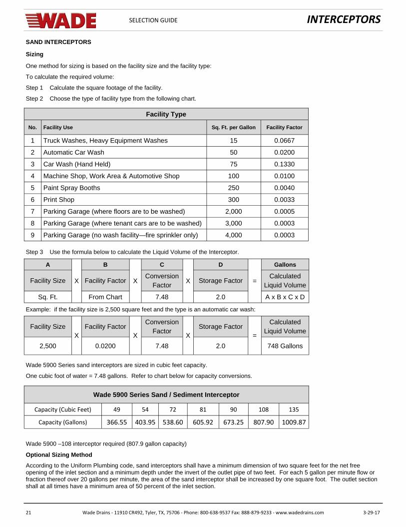
Sizing
One method for sizing is based on the facility size and the facility type:
To calculate the required volume:
Step 1 Calculate the square footage of the facility.
Step 2 Choose the type of facility type from the following chart.
1 Truck Washes, Heavy Equipment Washes
2 Automatic Car Wash
3 Car Wash (Hand Held)
4 Machine Shop, Work Area & Automotive Shop
5 Paint Spray Booths
6 Print Shop
7 Parking Garage (where floors are to be washed)
8 Parking Garage (where tenant cars are to be washed)
9 Parking Garage (no wash facility—fire sprinkler only)
Facility Type
15
50
75
100
250
300
2,000
3,000
4,000
No. Facility Use Sq. Ft. per Gallon Facility Factor
0.0667
0.0200
0.1330
0.0100
0.0040
0.0033
0.0005
0.0003
0.0003
Step 3 Use the formula below to calculate the Liquid Volume of the Interceptor.
Facility Size X Facility Factor X Conversion
Factor X Storage Factor =
Calculated Liquid Volume
Sq. Ft. From Chart 7.48 2.0 A x B x C x D
A B C D Gallons
Example: if the facility size is 2,500 square feet and the type is an automatic car wash:
Facility Size X
Facility Factor X
Conversion Factor
X Storage Factor
=
Calculated Liquid Volume
2,500 0.0200 7.48 2.0 748 Gallons
Wade 5900 Series sand interceptors are sized in cubic feet capacity.
One cubic foot of water = 7.48 gallons. Refer to chart below for capacity conversions.
Capacity (Cubic Feet) 49 54 72 81 90 108 135
Capacity (Gallons) 366.55 403.95 538.60 605.92 673.25 807.90 1009.87
Wade 5900 Series Sand / Sediment Interceptor
Wade 5900 –108 interceptor required (807.9 gallon capacity)
Optional Sizing Method
According to the Uniform Plumbing code, sand interceptors shall have a minimum dimension of two square feet for the net free opening of the inlet section and a minimum depth under the invert of the outlet pipe of two feet. For each 5 gallon per minute flow or fraction thereof over 20 gallons per minute, the area of the sand interceptor shall be increased by one square foot. The outlet section shall at all times have a minimum area of 50 percent of the inlet section.