green building index malaysianew.greenbuildingindex.org/files/resources/20090214 - gbi ms1525... ·...
TRANSCRIPT

GREEN BUILDING INDEXMALAYSIA
Ir CHEN Thiam Leong
FIEM, FASHRAE, MIFireE, PEng
MS 1525 : 2007
ACMV System
Energy Management System
PAM CPD 2009 Seminar

8. Air-conditioning and mechanical
ventilation (ACMV) system
8.1 Load calculations
8.2 System and equipment sizing
8.3 Separate air distribution systems
8.4 Controls
8.5 Piping insulation
8.6 Air handling duct system insulation
8.7 Duct construction
8.8 Balancing
8.9 ACMV systems
8.10 ACMV system equipment
8.11 ACMV system components
8.12 ACMV system equipment/component
– heat operated (absorption), cooling mode
8.13 System testing and commissioning
8.14 Operation and maintenance (O&M) manual
and as-built drawings
8.15 Preventive maintenance

“Air Conditioning is the control of the humidity of air by either increasing or decreasing its moisture content. Added to the control of the humidity is the control of temperature by either heating or cooling the air, the purification of the air by washing or filtering the air and the control of the air motion and ventilation.”
- Willis H. Carrier

Without the need for thermal
comfort, there will be no need for
buildings

8.1 Load calculations
8.1.1 Calculation procedures
Cooling design loads should be
determined in accordance with the
procedures described in ASHRAE
Handbooks, or other equivalent
publications.

8.1.2 Indoor design conditions
Comfort condition depends on various
factors including air temperature, mean radiant
temperature, humidity, clothing, metabolic rate
and air movement preference of the occupant.
The 3 main factors considered are:
• DRY BULB TEMPERATURE;
• RELATIVE HUMIDITY; AND
• AIR MOVEMENT (AIR VELOCITY)

8.1.3 Outdoor design conditions
a) dry bulb temperature 33.3 °°°°C
b) wet bulb temperature 27.2 °°°°C.

� You feel comfortable when metabolic heat is dissipated at the same rate it is produced.
� The human body needs to be maintained at a 37 ± 0.5 °C regardless of prevailing ambient condition.
� The higher the space RH, the lower the amount of heat the human body will be able to transfer by means of perspiration/evaporation.
� If indoor air temperature is high and RH is high (above 11.5 g vapour per kg dry air), the human body will feel uncomfortable.
� Generally, RH for indoor comfort condition SHOULD NOT EXCEED 70 %.

� Air movement is essential for comfort as it enhances
heat transfer between air and the human body and
accelerates cooling of the human body
� Air movement gives a feeling of freshness by
lowering skin temperature, and the more varied the air
currents in velocity and direction, the better the effect.
� A draught is created when temperature of moving air
is too low and/or the velocity is too high.
� At comfort room temperature (23 to 26 °C),
acceptable air velocity range is 0.15 to 0.50 m/s.

Indoor conditions of ac space for comfort cooling:
Design dry bulb temperature 23 º C – 26 °°°°C
Min dry bulb temperature 22 °°°° C
Design relative humidity 55 % – 70 %
Air movement 0.15m/s–0.50m/s
Max air movement 0.7 m/s


8.1.4 Ventilation
Outdoor air-ventilation rates should comply with the
3rd Schedule (By Law 41) Article 12(1) of Uniform
Building By Laws, 1984.
Exception:
Special occupancy or process requirements or source
control of air contamination or Indoor Air Quality
consideration.

MS1525 Design Application
Example:
Project consists of 3 distinct elements;
1. Podium – Retail
2. Block A – Residential Apartments
3. Block B – Office Tower

Step 1 – Estimate Cooling Loads for each in
terms of;
• Connected Load
• Diversified Load – Diversity Factors
• Peak Load
• Daily Load Profile – max and minimum

3,415763,992TOTAL
1,447347,360Block B
1,350324,000Block A
61892,632Podium
Connected
RT
Area Ft2
Connected load
72%
85%
50%
90%
2,461
1,230
675
556
Peak RT
Vs Peak load

750
250
250
250
Min
RT
30%2,4613,415TOTAL
20%1,2301,447Block B
37%6751,350Block A
45%556618Podium
Peak
RT
Connected
RT
Need to watch out for Minimum loads

8.2 System and Equipment Sizing
8.2.2 Where chillers are used and when the
design load is greater than 1,000 kWr
(280RT) , a minimum of either two
chillers or a single multi-compressor
chiller should be provided to meet the
required load.

8.2.4 Individual air cooled or water cooled direct
expansion (DX) units > 35 kWr
(reciprocating compressor) or 65 kWr
(scroll compressor) should consist of either
multi compressors or single compressor
with step/variable unloaders
Other than chillers ................

Ensure energy efficiency is optimised
during partial load operation of ac plant
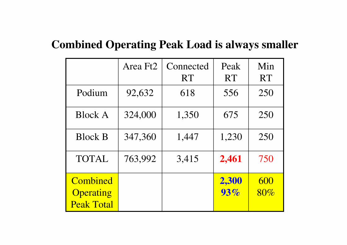
600
80%
2,300
93%
Combined
Operating
Peak Total
7502,4613,415763,992TOTAL
2501,2301,447347,360Block B
2506751,350324,000Block A
25055661892,632Podium
Min
RT
Peak
RT
Connected
RT
Area Ft2
Combined Operating Peak Load is always smaller

2 x 620RT,
2 x 310RT
3 x 340RT
3 x 280RT
Standalone
Plant
3720
150%
7502,461TOTAL
18602501,230Block B
1020250675Block A
840250556Podium
Total
Plant RT
Min
RT
Peak
RT
Standalone Plants are always accumulatively larger

600
2 x 620RT,
2 x 310RT
3 x 340RT
3 x 280RT
Standalone
Plant
5 x
600RT
3000
80%
10 chillers2,300Operating
Peak Total
37207502,461TOTAL
18602501,230Block B
1020250675Block A
840250556Podium
Common
Plant
Total
Plant RT
Min
RT
Peak
RT
Advantages of a Common Plant

8.9 ACMV systems
3 basic types discussed:
a) Central air-distribution systems
b) Central circulating water systems
c) Multiple units systems

Types of Airconditioning Systems:
Apartment Block
a) Refrigeration side
1) Part of centralised/district cooling chw system
2) DX Split units
3) VRV system
4) Air-cooled mini chw system
5) Other cutting edge systems viz LNG fired mini
absorption chiller with fuel cell
b) Airside
• FCUs: Free-throw and/or ducted

Retail Block
a) Refrigeration Side
1) Standalone chw system
2) Part of centralised/district cooling chw system
3) DX Water-cooled Packaged Units
4) DX Air-cooled Packaged Units
b) Airside
1) AHUs only
2) AHUs and/or FCUs

Retail Block cont’d
c) Other Strategies
1) VAV and/or CAV distribution
2) VAV diffusers
3) Low Level Displacement
4) Heat Recovery Wheels, Heat Pipes

Office Tower
a) Refrigeration Side
1) Standalone chw system
2) Part of centralised/district cooling chw system
3) DX Water-cooled Packaged Units
4) VRV System + other combinations
5) DX Air-cooled Packaged Units
6) DX WCPUs and mini WCPUs
b) Airside Side
• AHUs only
• AHUs and FCUs

Office Tower cont’d
c) Other Strategies
1) VAV terminals
2) VAV diffusers
3) UFAD
4) Chilled Slabs/Beams
5) Chilled Ceilings
6) Heat Recovery Wheels, Heat pipes
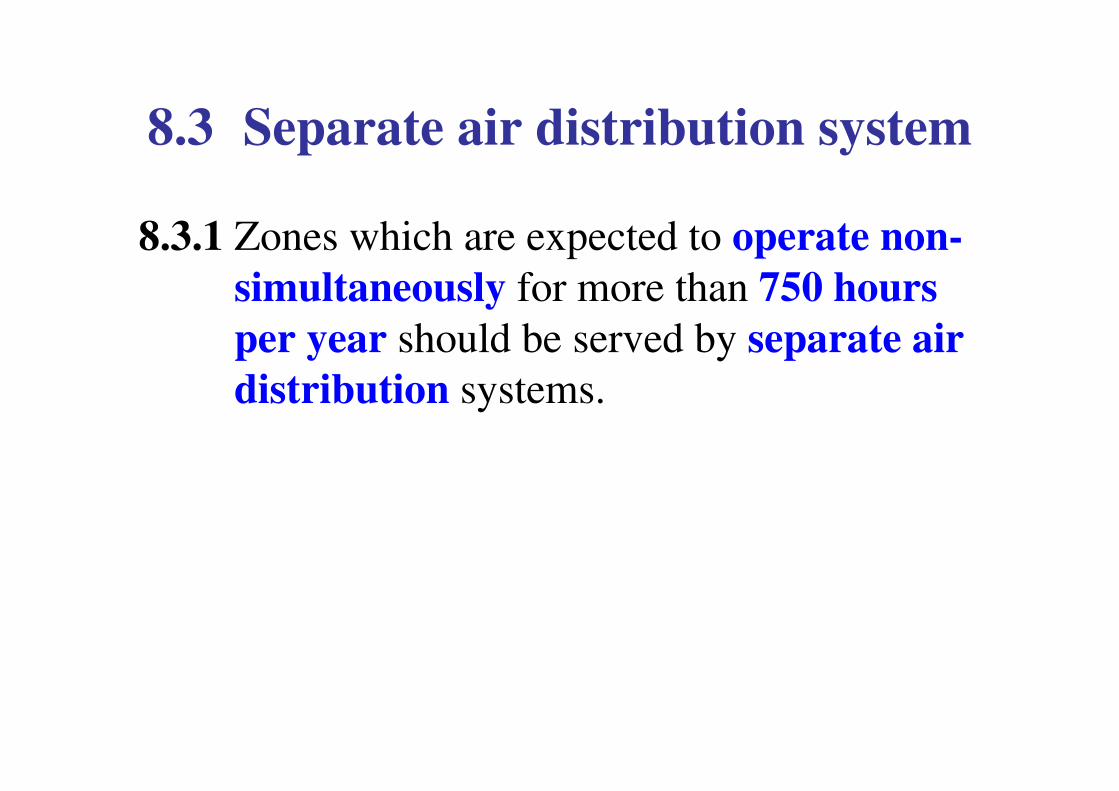
8.3 Separate air distribution system
8.3.1 Zones which are expected to operate non-
simultaneously for more than 750 hours
per year should be served by separate air
distribution systems.

Podium Retail
• Normally operate simultaneously
• Due to acoustic and duct size limits,
normally multiple AHUs are used
• What about outlets not tenanted?
• Separate AHUs for cinemas, bowling
alleys and the like due to different
operating hours
• AHU/FCUs for back of the house facilities

Block A - Apartments
• Fan coil units per room – independent
zoning

Block B – Office Tower
• Normally operate simultaneously on floor
basis
• 3 AHUs per floor offers excellent
flexibility
• What about server rooms operating 24/7?

8.3.3 Separate air distribution systems should be
considered for areas of the building having
substantially different cooling
characteristics, such as perimeter zones (3
m room depth) in contrast to interior zones.
• Podium Application?
• Office Block Application:
Separate CAV AHU
Separate VAV units
VAV diffusers

8.3.4 For air conditioned space requiring exhaust
air volume in excess of 3,400 m3/h
(2000cfm), not less than 85 % of non
conditioned make up air should be
introduced directly into the space
concerned unless the exhausted
conditioned air is utilised for secondary
cooling purposes.
Alternatively, heat recovery devices should
be provided.

Especially applicable for Kitchen hoods in
Retail and Office Tower.

Kitchen Hood
Exhaust = V lps
exhaust air duct
Make up air duct
Make up air duct
Make up = 0.85V lps
Make up drawn from
ac sys = 0.15V lps
Restaurant
+ve pressure for
odour control
Kitchen
–ve pressure

8.4 Controls
8.4.1.1 Zoning for temperature control
At least one thermostat for regulation of space
temperature should be provided for:
a) each separate system; and
b) each separate zone
As a minimum each floor of a building should
be considered as a separate zone.
On a multi-storey building where the perimeter
system offsets only the transmission gains of
the exterior wall, an entire side of uniform
exposure may be zoned separately.
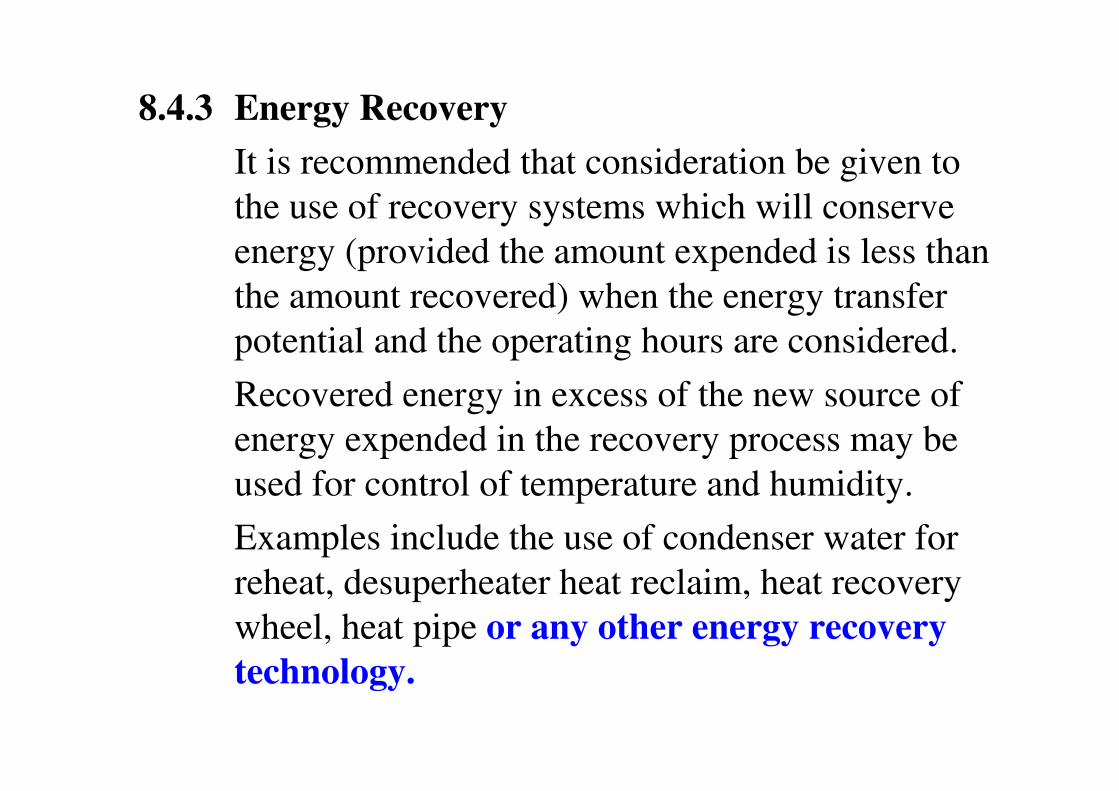
8.4.3 Energy Recovery
It is recommended that consideration be given to
the use of recovery systems which will conserve
energy (provided the amount expended is less than
the amount recovered) when the energy transfer
potential and the operating hours are considered.
Recovered energy in excess of the new source of
energy expended in the recovery process may be
used for control of temperature and humidity.
Examples include the use of condenser water for
reheat, desuperheater heat reclaim, heat recovery
wheel, heat pipe or any other energy recovery
technology.

At most, likely to be applicable to areas with
high occupancy density such as auditorium and
large function rooms in Office Tower, and
cinemas in Podium.

8.4.4 Off-hour control
8.4.4.1ACMV system shall be equipped with automatic controls capable of accomplishing a reduction of energy use for example through equipment shutdown during periods of non-use or alternative use of the spaces served by the system.
Exceptions:
a) systems serving areas which are expected to operate continuously; and
b) equipment with a connected load of 2 kWeor less may be controlled by readily accessible manual off-hour controls.

8.4.4.2 Outdoor air supply and exhaust systems should be provided with motorised or gravity dampers or other means of automatic volume shut-off or reduction during period of non-use or alternate use of the spaces served by the system.
Exceptions:
a) systems serving areas which are expected to operate continuously;
b) systems which have a design air flowrate of 1,800 m3/h (1,000cfm) or less;
c) gravity and other non-electrical ventilation systems may be controlled by readily accessible manual damper controls; and
d) where restricted by process requirements such as combustion air intakes.

Likely to be applicable to systems installed for
auditorium and large function areas which
are not frequently used.
The exceptions on exhaust quantity will apply
to small domestic type kitchens and pantries.

8.4.4.4 For buildings where occupancy patterns are
not known at time of system design, such as
speculative buildings, isolation areas may
should be pre-designed.
• Very applicable for retail podium where
demarcated retail lots are best determined
• Also applicable for office floor and in this
instance, 3 zones per floor are already projected.

8.4.4.5 Zones may be grouped into a single isolation
area provided the total conditioned floor area
does not exceed 250 m2 per group nor include
more than one floor unless variable air
volume or equivalent devices are incorporated.
Use of outside economy air cycle design where
feasible should be considered.

8.4.5 Mechanical ventilation control
Each mechanical ventilation system (supply
and/or exhaust) should be equipped with a
readily accessible switch or other means for
shut-off or volume reduction when ventilation is
not required. Examples of such devices would
include timer switch control, thermostat control,
duty cycle programming and CO/CO2 sensor
control.
• Applicable to the basement car park level.

Floor to Floor Heights
• Apartment Block
9F – 27F = 3050 : OK
• Retail Podium
GF = 6600, 1F – 2F = 4500 : OK
• Carpark Floors
B3 – B1 & 3F – 7F = 3050 : OK
• Office Tower
9F – 35F = 3050 : limitation to ducted system?

8.4.6 Fan System Efficiency
For fan system with air flowrate >17000 m3/h
and operating for more than 750 hours a year,
the power required by the motor for the entire
fan system at design conditions should not
exceed 0.45 W per m3/h of air flowrate.

Pumps
12%Towers
2%
Chiller
38%Fans
48%

1. Volume flow is directly proportional to fan speed
Q1 / Q2 = (N1 / N2)
2. Pressure is directly proportional to square of fan speed
SP1 / SP2 = (N1 / N2)2
3. Fan power is directly proportional to cube of fan speed
P1 / P2 = (N1 / N2)3
where Q = Air Volume Flowrate
N = Rotational Speed
SP = Static Pressure
P = Power
Fan Laws

1. Q1 / Q2 = (N1 / N2)
ie Q = k N
2. SP1 / SP2 = (N1 / N2)2
ie SP = k’ N2 = k’ Q2
which means if fan speed is doubled, its static pressure is increased 22 = 4 folds and similarly for the same duct, if airflow is doubled, its friction loss is increased 4 folds
3. P1 / P2 = (N1 / N2)3
ie P = k” N3
which means if fan speed is doubled, power is increased 23 = 8 folds !!

8.5 Piping Insulation
All piping should be adequately insulated to prevent
excessive energy losses. Additional insulation with
vapour barriers may be required to prevent condensation
under some conditions.
Exceptions:
a) Piping installed within ACMV equipment.
b) Piping at fluid temperatures 23 to 49 °C
c) When the heat loss and/or heat gain of the
piping, without insulation, does not increase
the energy requirements of the building.
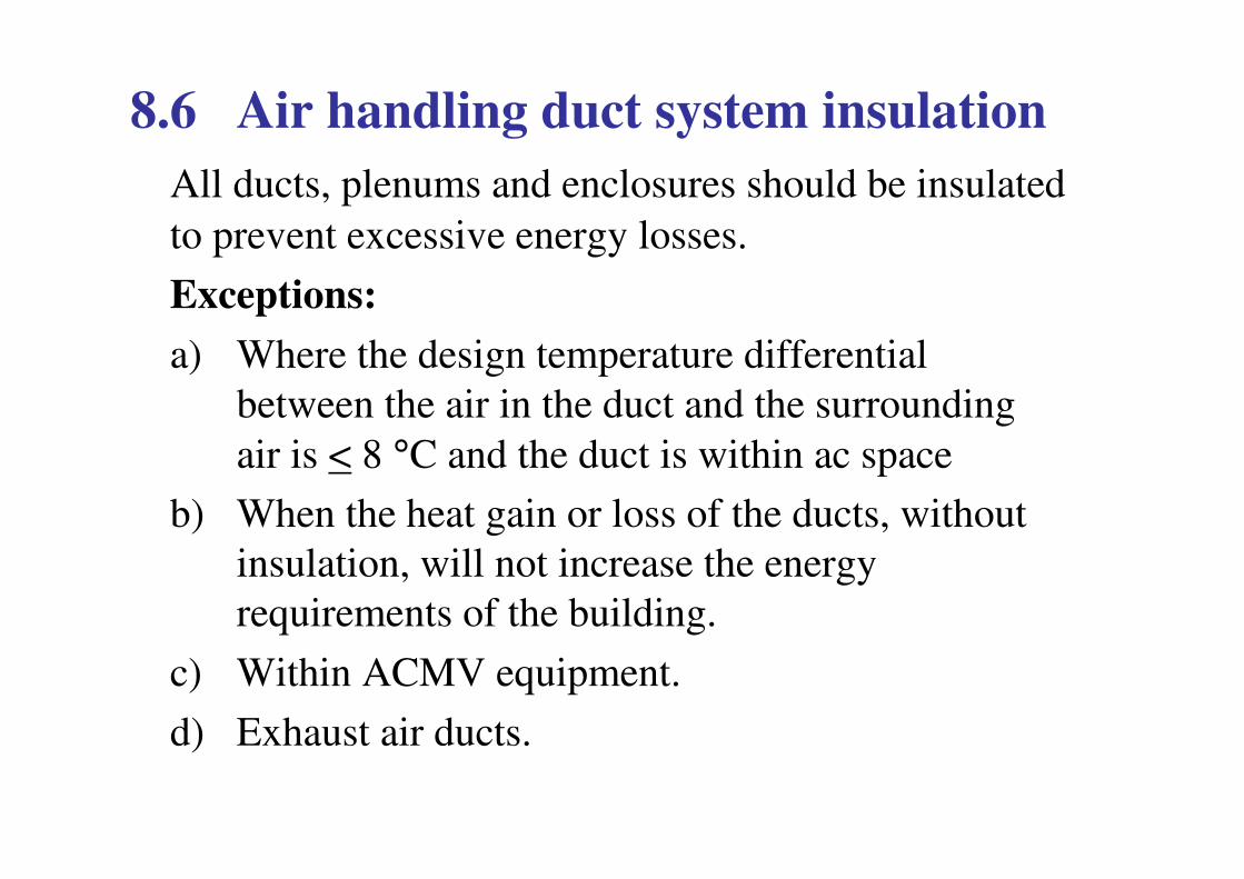
8.6 Air handling duct system insulation
All ducts, plenums and enclosures should be insulated
to prevent excessive energy losses.
Exceptions:
a) Where the design temperature differential
between the air in the duct and the surrounding
air is < 8 °C and the duct is within ac space
b) When the heat gain or loss of the ducts, without
insulation, will not increase the energy
requirements of the building.
c) Within ACMV equipment.
d) Exhaust air ducts.

8.7 Duct construction
All ductwork should be constructed in accordance with HVAC Duct Construction Standards Metal and Flexible published by SMACNA or any other equivalent duct construction standards.
8.7.1
High-pressure and medium-pressure ducts should be leak tested in accordance with HVAC Air Duct Leakage Test Manual published by SMACNA or any other equivalent standards, with the rate of leakage not to exceed the maximum rate specified.

8.7.2
When low pressure supply air ducts are located outside
of the conditioned space (except return air plenums),
all transverse joints should be sealed using mastic or
mastic plus tape or equivalent material. For fibrous
glass ductwork, pressure sensitive tape is acceptable.
8.7.3
Automatic or manual dampers installed for the purpose
of shutting off outside air intake for ventilation air
should be designed with tight shut-off
characteristics to minimise air leakage.

8.8 Balancing
The system design should provide means for
balancing the air and water system such as but not
limited to dampers, temperature and pressure test
connections and balancing valves.

Table 19. Unitary air conditioners, electrically driven:
3.6Split system & single package≥ 35kWr
3.5Split system & single package≥ 19kWr
< 35kWr
3.0Split system & single package<19kWrWater and
evaporatively
cooled
2.5Split system & single package≥ 35kWr
2.6Split system & single package≥ 19kWr
< 35kWr
2.7
2.7
Split system
Single package
<19kWrAir cooled
with
condenser
Min. COPSub-categorySizeEquipment

Table 21. Water chilling packages, electrically driven:
5.7 COP(0.62kWe/RT) or 5.2 NPLV≥ 1060kWr
5.2 COP(0.68kWe/RT) or 4.7 NPLV< 1060kWrWatercooled
Centrifugal
5.4 COP(0.65kWe/RT) or 5.8 NPLV≥ 1060kWr
4.4 COP(0.8kWe/RT) or 4.7 NPLV≥ 530 < 1060kWr
4.0 COP or 4.2 NPLV<530kWr(150RT)Watercooled
Rotary
3.9 COP(0.9kWe/RT) or 4.0 NPLVAll capacitiesWatercooled
Recip or scroll
2.9 COP(1.21kWe/RT) or 3.0 NPLV≥ 1060kWr
2.8 COP(1.26kWe/RT) or 2.9 NPLV≥ 530kWr
<1060kWr(300)
2.7 COP(1.3kWe/RT) or 2.8 NPLV≥ 105kWr
<530kWr(150RT)
2.6 COP(1.36kWe/RT) or 2.8 NPLV<105kWr (30RT)Aircooled
with
condenser
Min COP or Min NPLV COPSizeEquipment

8.13 System testing & commissioning
• Air system balancing should minimise throttling
losses and fan speed adjusted to meet design flow
conditions.
• Hydraulic system balancing should minimise
throttling losses and pump impeller/s trimmed or
pump speed adjusted to meet design flow conditions.
• ACMV control systems should be tested to assure that
control elements are calibrated, adjusted and in
proper working condition.

8.14 O&M and As-Builts
• An operation and maintenance (O & M) manual and as-built drawings should be provided to the owner. Manual should include basic data relating to the operation and maintenance of ACMV systems and equipment. Required routine maintenance action should be clearly identified. Where applicable, ACMV controls information such as diagrams, schematics, control sequence descriptions and maintenance and calibration information should be included.
• As-built drawings should contain information relating to rated capacities of all ac plants which includes, but not limited to AHUs and fans.

8.15 Preventive Maintenance
• The owner should implement preventive maintenance
system and schedule periodic maintenance on all the
critical items of air-conditioning systems such as
compressors, cooling towers, pumps, condensers, air
handlers, controls, filters and piping.

Some important EE Design Issues
• Solar heat gain from building envelope and
heat from light fittings can contribute up to
70% of total cooling capacity required
• Every Watt saved in lighting reduces
building’s power consumption by 1.2 to 1.3
Watts
• Daylight will effectively penetrate up to 1.5X
the height of the window

End of
Presentation
Chapter 8 - ACMV

9. Energy Management Control System
9.1 Energy Management System (EMS)
9.2 Control of equipment
9.3 Monitoring of equipment
9.4 Integration of equipment subsystems
9.5 Energy consuming areas
9.6 Application of EMS to the ACMV system
9.7 Application of EMS to the lighting system
9.8 Application of EMS to Energy Audit
9.9 Characteristics of EMS

9.1 Energy Management System (EMS)
The Energy Management System (EMS) is a
subset of the Building Automation System
function. It should be considered for buildings
having area greater than 4,000 m2 of air-
conditioned space. Generally, the Building
Automation System has 3 functions:
a) control of equipment;
b) monitoring of equipment; and
c) integration of equipment sub-systems.

9.2 Control of equipment
The purpose of the control of equipment is to save
energy.
This is performed by the EMS function of the
Building Automation System.

9.3 Monitoring of equipment
The purpose of monitoring the equipment is to
improve the efficiency of operations personnel by:
a)providing centralised information of current
equipment conditions;
b)providing historical information of equipment
conditions;
c)providing a “management by exception” function
to alert the operator of any abnormal equipment
conditions; and
d)providing analysis tools to aid in the study of
equipment operations.

9.4 Integration of equipment sub-systems
Equipment subsystems are integrated for the purpose
of improving:
a)safety/security; for example, in the event of
fire, AHUs can be used to create a sandwich system
for smoke control;
b)indoor air quality; for example, by utilising the
smoke purging system for periodic air purging
to achieve good indoor air quality;

c)information management; by allowing
information from multiple equipment
subsystems to be stored and reported in a
consistent format; and
d)overall system reliability;

B A S

9.5 Energy consuming areas
9.5.1 ACMV system
This system is typically the largest energy consumer in the building and has the largest savings potential. The EMS must place special emphasis on the ACMV system
9.5.2 Lighting system
The lighting system is typically the second largest energy consumer in the building and should also be considered for inclusion in the EMS

9.5.3 Others
Any other large energy consuming equipment
such as water pump sets, electric heaters and
others should be included under the EMS
programme. However, it is typically not
appropriate to apply an EMS to control other
equipment, such as computers etc.

9.6 Application of EMS to ACMV system
9.6.1 Central plant
In buildings where chillers are used, the EMS should
be used to issue start/stop commands to the chiller
control panel. The start /stop commands should be
based on:
a) time schedules to match occupancy patterns;
and
b) selection of the most energy efficient
combination of chillers to satisfy building
load; this is known as chiller sequencing
(chiller optimisation programming).

Chillers are typically supplied with microprocessor based control panels. Where possible, a high level data interface between the chiller control panel and the EMS should be provided.
The chiller is typically the largest single energy consumer in the building. The energy consumed by a chiller decreases as the set point of the leaving chilled water is increased.
The EMS should automatically increase the set point of the leaving chilled water whenever possible to minimise energy consumption.

The EMS may adjust the set point based on (but not
limited to):
a) time schedule;
b) outdoor air temperature/enthalpy;
c) maximum AHU valve position; and
d) indoor relative humidity condition

9.6.2 AHUs
Next to the chiller, AHUs are typically the largest
consumers of energy in the building.
The EMS should have the facility to start and stop
AHUs based on a time schedule.
For further energy savings, the cooling coil valve of
AHUs should be controlled by a microprocessor
based controller which integrates with the EMS.
Where permitted by design, the speed of the AHU
fan should be decreased and the set point of the
cooling valve control loop should be increased to
minimise energy consumption.

9.6.3 Terminal Units
Terminal units include variable air volume
(VAV) boxes, fan coil units (FCU) and split units
should be start/stop by the EMS.
Some applications may require a number of
FCUs or split units to be grouped together as a
common zone for start/stop control by the EMS.

9.6.4 Mechanical ventilation
Where appropriate the EMS should start/stop
mechanical ventilation equipment such as supply or
exhaust fans.
Some applications may require a number of fans to be
grouped together as a common zone for start/stop
control by the EMS.
Control should be based on, but not limited to:
a) time schedules;
b) CO/CO2 level in parking garages or CO2 level
in large rooms with highly variable occupancy;
c) duty cycling algorithm.

9.7 Application of EMS to Lighting system
9.7.1
Lighting systems shall be provided with manual, automatic or programmable controls except:
a) those required for emergency lighting;
b) those required for exit lighting; and
c) continuous lighting required for security purposes.
The minimum number of controls shall be not less
than one for every 1,000 W of connected lighting
power .
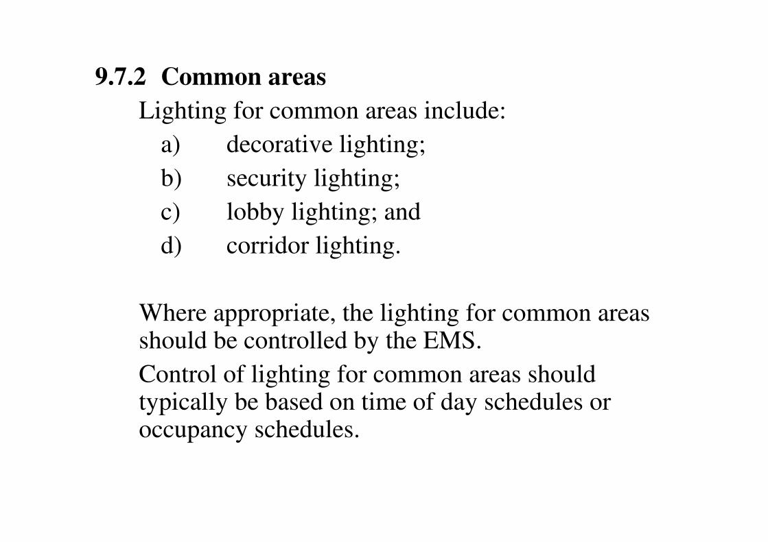
9.7.2 Common areas
Lighting for common areas include:
a) decorative lighting;
b) security lighting;
c) lobby lighting; and
d) corridor lighting.
Where appropriate, the lighting for common areas should be controlled by the EMS.
Control of lighting for common areas should typically be based on time of day schedules or occupancy schedules.

9.7.3 Work Areas
In cases where the EMS controls the lighting in the
work areas, local override switches should be
provided to allow localised control.
The status of these switches should be monitored
by the EMS so that the EMS knows the command
which has been sent to the lights.
Control of lighting for work areas should typically
be based on occupancy schedules.

9.8 Application of EMS to Energy Audit
Buildings provided with EMS shall be equipped with
data logging facilities for the collation of data for
energy auditing.
Suitable means or facilities for the monitoring of
energy consumption (sub-metering) should be
provided to all incoming power supply to a building
and the outgoing sub-circuits serving, but not limited,
to the following :

a) central air-conditioning system;
b) lift and escalator system;
c) major water pumping system;
d) general power supply; and
e) lighting supply to tenancy areas and landlord
areas.

9.9 Characteristics of EMS
The EMS should be supplied with a full complement
of energy management features including but not
limited to:
a) direct digital control algorithms;
b) starting and stopping of equipment based on
a time schedule;
c) temporary override of the time schedules to
accommodate changes in usage;
d) chilled water leaving and/or entering
temperature reset algorithm;
e) control loop set point reset algorithm;

f) chiller sequencing and optimisation and
sequencing algorithm;
g) demand limiting algorithm; and
h) duty cycling algorithm.
The EMS should come with an energy tracking and
reporting system so that a historical record of energy
usage is maintained for analysis and energy audit
purposes.

ENERGY CONSUMPTION (kWh)
0
20,000
40,000
60,000
80,000
100,000
120,000
140,000
160,000
180,000
JAN FEB MAR APR MAY JUN JUL AUG SEP OCT NOV DEC
1999
2000
2001
2002
2003
2004

AVERAGE ENERGY CONSUMPTION (kWh)
156,083
139,333
128,833 128,667 128,417 129,111
0
20,000
40,000
60,000
80,000
100,000
120,000
140,000
160,000
1999 2000 2001 2002 2003 2004

End of
Presentation