green cloud - load balancing, load consolidation using vm
TRANSCRIPT

Western Kentucky UniversityTopSCHOLAR®
Masters Theses & Specialist Projects Graduate School
Fall 2017
Green Cloud - Load Balancing, LoadConsolidation using VM MigrationManh Duc DoWestern Kentucky University, [email protected]
Follow this and additional works at: https://digitalcommons.wku.edu/theses
Part of the Systems Architecture Commons
This Thesis is brought to you for free and open access by TopSCHOLAR®. It has been accepted for inclusion in Masters Theses & Specialist Projects byan authorized administrator of TopSCHOLAR®. For more information, please contact [email protected].
Recommended CitationDo, Manh Duc, "Green Cloud - Load Balancing, Load Consolidation using VM Migration" (2017). Masters Theses & Specialist Projects.Paper 2059.https://digitalcommons.wku.edu/theses/2059

GREEN CLOUD - DYNAMIC LOAD BALANCING AND LOAD CONSOLIDATIONUSING VM LIVE MIGRATION
A ThesisPresented to
The Faculty of the Department of Computer ScienceWestern Kentucky University
Bowling Green, Kentucky
In Partial FulfillmentOf the Requirements for the Degree
Master of Science
By Manh Do
December 2017

DEDICATION
To my mother, father, sister, and friends.
&
To the faculty of the Computer Science Department at Western Kentucky University.

ACKNOWLEDGMENTSMy appreciation goes to my professor and adviser, Dr. Michael Galloway. I am
grateful for his support and advice throughout my Masters program. I truly appreciate the
sacrifices he has made to meet with me,to help me attend conferences, and to provide his
students with a place and supplies to do research.
I have never seen someone so invested in his students as Dr. Galloway. He strives
to find his students funding and built a lab for them to work. On one occasion he even
took me to tour a potential school in which I could pursue my Ph.D. I consider him to be a
friend as well as a mentor and hope to keep in touch throughout the future. Thank you Dr.
Galloway for all that you have done for the Students at WKU.
To Dr. James Gary, head of the Computer Science Department and the first contact
I made at WKU, thank you. Dr. Gary always did whatever he could to help students out
however he could. Dr. Gary helped me transition into the undergraduate program and did
the same when I began the Masters program. He helped me secure the funding to go to a
conference in New York City giving me a life experience that I will never forget. On top of
all that he is one of the funniest people I know. Thank you Dr. Gary for everything you’ve
done over these past many years.
To Dr. Xia, the graduate student adviser or the Computer Science Department,
Thank you for your help and advice through my graduate career. I would also like to
express my appreciation for giving me the opportunity to be a graduate assistant. Thank
you!
iv

To the rest of the Western Kentucky University faculty, thank you! I would not be
where I am today without you. I apologize that I cannot thank everyone of you individually.
Thank you all for what you have done for me. I truly appreciate it.
I would also like to acknowledge My friends and family. Thank you for your con-
tinued support. I appreciate everything you do. Special thanks to all my friends cloud
group. Thank you for everything!
Finally, I would like to thank the financial support provided by the Department of
Computer Science, the graduate school, and Ogden College. Thank you for the opportuni-
ties you have provided me at WKU.
v

CONTENTS
1 INTRODUCTION . . . . . . . . . . . . . . . . . . . . . . . . . . . . . . . . . . 1
2 BACKGROUND . . . . . . . . . . . . . . . . . . . . . . . . . . . . . . . . . . 4
2.1 Cloud Computing Concept . . . . . . . . . . . . . . . . . . . . . . . . . . 4
2.1.1 History . . . . . . . . . . . . . . . . . . . . . . . . . . . . . . . . 4
2.1.2 Cloud Computing Concept . . . . . . . . . . . . . . . . . . . . . . 5
2.1.3 Cloud Computing Advantage and Disadvantage . . . . . . . . . . . 13
2.1.4 Cloud Characteristics . . . . . . . . . . . . . . . . . . . . . . . . . 14
2.1.5 Cloud Computing Components and Energy Usage Model: A Typi-cal Example . . . . . . . . . . . . . . . . . . . . . . . . . . . . . . 16
2.2 Green Cloud Computing . . . . . . . . . . . . . . . . . . . . . . . . . . . 20
2.2.1 Green Computing . . . . . . . . . . . . . . . . . . . . . . . . . . . 20
2.2.2 Some Solutions to Reach Green Computing . . . . . . . . . . . . . 20
2.2.3 Green Cloud . . . . . . . . . . . . . . . . . . . . . . . . . . . . . 21
2.2.4 Feature of Clouds Enabling Green Cloud . . . . . . . . . . . . . . 23
2.2.5 VM Migration . . . . . . . . . . . . . . . . . . . . . . . . . . . . 24
vi

2.2.6 Load Balancing . . . . . . . . . . . . . . . . . . . . . . . . . . . . 31
2.2.7 Load Consolidation . . . . . . . . . . . . . . . . . . . . . . . . . . 32
2.3 Related Work . . . . . . . . . . . . . . . . . . . . . . . . . . . . . . . . . 33
3 PROPOSED ARCHITECTURE . . . . . . . . . . . . . . . . . . . . . . . . . . 37
3.1 Architecture . . . . . . . . . . . . . . . . . . . . . . . . . . . . . . . . . . 37
3.2 Network Filesystem . . . . . . . . . . . . . . . . . . . . . . . . . . . . . . 38
4 LIVE VIRTUAL MACHINE MIGRATION . . . . . . . . . . . . . . . . . . . . 41
4.1 Pre-copy VM Migration . . . . . . . . . . . . . . . . . . . . . . . . . . . 41
4.2 Live VM Migration supported by KVM . . . . . . . . . . . . . . . . . . . 42
5 DYNAMIC LOAD BALANCING . . . . . . . . . . . . . . . . . . . . . . . . . 44
5.1 Dynamic Load Balancing . . . . . . . . . . . . . . . . . . . . . . . . . . . 44
5.1.1 Distributed Workload . . . . . . . . . . . . . . . . . . . . . . . . . 45
5.1.2 Optimize CPU’s Usage . . . . . . . . . . . . . . . . . . . . . . . . 46
5.1.3 Resource Provisioning . . . . . . . . . . . . . . . . . . . . . . . . 50
5.2 Implementation and Results . . . . . . . . . . . . . . . . . . . . . . . . . 51
5.2.1 Cloud Environment Setup . . . . . . . . . . . . . . . . . . . . . . 52
5.2.2 Distributed Workload Implementation . . . . . . . . . . . . . . . . 53
5.2.3 Optimization of CPU’s usage . . . . . . . . . . . . . . . . . . . . 53
6 LOAD CONSOLIDATION . . . . . . . . . . . . . . . . . . . . . . . . . . . . . 59
6.1 Bin Packing Problem . . . . . . . . . . . . . . . . . . . . . . . . . . . . . 60
6.2 My Approach for Load Consolidation . . . . . . . . . . . . . . . . . . . . 62
6.3 Test Cases and Results . . . . . . . . . . . . . . . . . . . . . . . . . . . . 62
vii
7 FUTURE WORK . . . . . . . . . . . . . . . . . . . . . . . . . . . . . . . . . . 68
8 CONCLUSION . . . . . . . . . . . . . . . . . . . . . . . . . . . . . . . . . . . 70
REFERENCES . . . . . . . . . . . . . . . . . . . . . . . . . . . . . . . . . . . . . 71
APPENDICES . . . . . . . . . . . . . . . . . . . . . . . . . . . . . . . . . . . . . 75
A APPENDIX A: SETTING UP THE ARCHITECTURE . . . . . . . . . . . . . . 76
A.1 Preparing Compute Node . . . . . . . . . . . . . . . . . . . . . . . . . . . 76
A.2 Setting Up The Network Files . . . . . . . . . . . . . . . . . . . . . . . . 76
A.3 Building the Share-storage Network (using GlusterFS) . . . . . . . . . . . 77
B APPENDIX B: LIVE VIRTUAL MACHINE MIGRATION . . . . . . . . . . . . 78
C APPENDIX C: DYNAMIC LOAD BALANCING . . . . . . . . . . . . . . . . . 79
C.1 Setting Up the Head Node . . . . . . . . . . . . . . . . . . . . . . . . . . 79
C.2 Client . . . . . . . . . . . . . . . . . . . . . . . . . . . . . . . . . . . . . 79
C.3 Server . . . . . . . . . . . . . . . . . . . . . . . . . . . . . . . . . . . . . 79
C.4 All functions need for load balancing and load consolidation . . . . . . . . 79
C.5 Distributed Workload . . . . . . . . . . . . . . . . . . . . . . . . . . . . . 79
C.6 Optimize the CPU’s utilization . . . . . . . . . . . . . . . . . . . . . . . . 79
D APPENDIX D: LOAD CONSOLIDATION . . . . . . . . . . . . . . . . . . . . 86
D.1 Load Consolidation . . . . . . . . . . . . . . . . . . . . . . . . . . . . . . 86
viii
2.1 Three bands used to classify PMs [Telkikar, Talele, Vanarse, and Joshi, 2014] 5
2.2 Model of grid computing [Shanmugam and Iyengar, 2016] . . . . . . . . . 5
2.3 Hyper Cycle in 2011 of Gartner Group. [Cuccureddu, 2011] . . . . . . . . 7
2.4 KVM Architecture [Botero, Szefer, and Lee, 2013] . . . . . . . . . . . . . 10
2.5 IaaS cloud Service [Erl, Mahmood, and Puttini, 2013] . . . . . . . . . . . . 11
2.6 PaaS cloud Service [Erl et al., 2013] . . . . . . . . . . . . . . . . . . . . . 12
2.7 SaaS cloud Service [Erl et al., 2013] . . . . . . . . . . . . . . . . . . . . . 13
2.8 Cloud Characteristics . . . . . . . . . . . . . . . . . . . . . . . . . . . . . 15
2.9 Cloud Components [Garg and Buyya, 2011] . . . . . . . . . . . . . . . . . 16
2.10 Energy Usage Model of a CDC [Emerson Network Power, 2009] . . . . . . 19
2.11 VM Migration in Load Balancing [Raza, Patle, and Arya, 2012] . . . . . . 28
2.12 VM Migration in Load Consolidation on CDC [Ahmad, Gani, hamid, Madani,Xia, and Madanii, 2015] . . . . . . . . . . . . . . . . . . . . . . . . . . . 29
2.13 VM Migration Pattern [Ahmad et al., 2015] . . . . . . . . . . . . . . . . . 30
2.14 Classification of Load Balancing Algorithms [Sahu and Pateriya, 2013] . . 31
2.15 Load Consolidation Steps [Feller, Morin, and Feller, 2012] . . . . . . . . . 33
2.16 Green Cloud Architecture [Liu, Wang, Liu, Jin, He, Wang, and Chen, 2009] 36
3.1 Logical View of a Server Cluster [Cisco, 2008] . . . . . . . . . . . . . . . 38
3.2 My Network Cloud Cluster . . . . . . . . . . . . . . . . . . . . . . . . . . 39
3.3 Distributed Volume in Glusterfs [Readthedocs.io, 2017] . . . . . . . . . . . 40
ix
LIST OF FIGURES

5.1 Three bands used to classify PMs [Telkikar et al., 2014] . . . . . . . . . . . 47
5.2 Resource Provisioning . . . . . . . . . . . . . . . . . . . . . . . . . . . . 51
5.3 Workload Distribution . . . . . . . . . . . . . . . . . . . . . . . . . . . . 53
5.4 LB -Test Case 1: Mixed VM Workloads . . . . . . . . . . . . . . . . . . . 56
5.5 Dynamic Load Balancing - Light Workload . . . . . . . . . . . . . . . . . 56
5.6 LB - Heavy Workload . . . . . . . . . . . . . . . . . . . . . . . . . . . . . 57
5.7 Dynamic Load Balancing - Moderate Workload . . . . . . . . . . . . . . . 58
6.1 Next Fit algorithm . . . . . . . . . . . . . . . . . . . . . . . . . . . . . . . 61
6.2 First Fit algorithm . . . . . . . . . . . . . . . . . . . . . . . . . . . . . . . 61
6.3 First Fit Decreasing Algorithm . . . . . . . . . . . . . . . . . . . . . . . . 61
6.4 LC - TB 1: Mix VM Workload . . . . . . . . . . . . . . . . . . . . . . . . 63
6.5 LC - Test Case 1: Mix VM Workload . . . . . . . . . . . . . . . . . . . . 63
6.6 LC - TB 2: Light VM Workload . . . . . . . . . . . . . . . . . . . . . . . 63
6.7 LC - Test Case 2: Light VM Workload . . . . . . . . . . . . . . . . . . . . 64
6.8 LC - TB 3: Moderate VM Workload . . . . . . . . . . . . . . . . . . . . . 64
6.9 LC - Test Case 3: Moderate VM Workload . . . . . . . . . . . . . . . . . . 65
6.10 LC - TB 4: Heavy VM Workload . . . . . . . . . . . . . . . . . . . . . . . 65
6.11 LC - Test Case 4: Heavy VM Workload . . . . . . . . . . . . . . . . . . . 66
6.12 The comparison between CPU utilization and Energy Consumption . . . . 66
6.13 Energy Saving after applying Load Consolidation . . . . . . . . . . . . . . 67
A.1 /etc/network/interfaces File. . . . . . . . . . . . . . . . . . . . . . . . . . 76
C.1 client.py. . . . . . . . . . . . . . . . . . . . . . . . . . . . . . . . . . . . . 79
x

C.2 server.py. . . . . . . . . . . . . . . . . . . . . . . . . . . . . . . . . . . . 80
C.3 allFunc.py. . . . . . . . . . . . . . . . . . . . . . . . . . . . . . . . . . . 81
C.4 distributeWorkload.py. . . . . . . . . . . . . . . . . . . . . . . . . . . . . 82
C.5 (continue) distributeWorkload.py. . . . . . . . . . . . . . . . . . . . . . . 83
C.6 CPUOtimization.py. . . . . . . . . . . . . . . . . . . . . . . . . . . . . . . 84
C.7 (continue) CPUOtimization.py . . . . . . . . . . . . . . . . . . . . . . . . 85
D.1 loadConsolidation.py . . . . . . . . . . . . . . . . . . . . . . . . . . . . . 87
xi

LIST OF ABBREVIATIONS
API Application Program Interface
AWS Amazon Web Services
CDC Cloud Data Center
CPU Central Processing Unit
EC2 Elastic Compute Cloud TM
GAE Google App Engine TM
IaaS Infrastructure as a Service
IBM International Business Machines
ICT Information and Communications Technology
IP Internet Protocol
IT Information Technology
KVM Kernel-based Virtual Machine
OS Operating System
PaaS Platform as a Service
PM Physical Machine
QEMU Quick Emulator
RAM Random Access Memory
SaaS Software as a Service
SLA Service Level Agreement
SSH Secure Shell
xii

TWH TeraWatt Hour
VM Virtual Machine
VT Virtualization Extensions
WAH Windowns Azure Hypervisor
XEN Hypervisor
xiii

GREEN CLOUD - DYNAMIC LOAD BALANCING AND LOAD CONSOLIDATIONUSING VM LIVE MIGRATION
December 2017Manh Do 85 Pages
Directed by: Dr. Michael Galloway, Dr. Zhonghang Xia, Dr. James Gary
Department of Computer Science Western Kentucky University
Recently, cloud computing is a new trend emerging in computer technology with
a massive demand from the clients. To meet all requirements, a lot of cloud data centers
have been constructed since 2008 when Amazon published their cloud service. The rapidly
growing data center leads to the consumption of a tremendous amount of energy even cloud
computing has better improved in the performance and energy consumption, but cloud data
centers still absorb an immense amount of energy. To raise company’s income annually,
the cloud providers start considering green cloud concepts which gives an idea about how
to optimize CPU’s usage while guaranteeing the quality of service. Many cloud providers
are paying more attention to both load balancing and load consolidation which are two
significant components of a cloud data center.
Load balancing is taken into account as a vital part of managing income demand,
improving the cloud system’s performance. Live virtual machine migration is a technique
to perform the dynamic load balancing algorithm. To optimize the cloud data center, three
issues are considered: First, how does the cloud cluster distribute the virtual machine (VM)
requests from clients to all physical machine (PM) when each computer has a different
capacity. Second, what is the solution to make CPU’s usage of all PMs to be nearly equal?
Third, how to handle two extreme scenarios: rapidly rising CPU’s usage of a PM due to
sudden massive workload requiring VM migration immediately and resources expansion
xiv

to respond to substantial cloud cluster through VM requests. In this chapter, we provide an
approach to work with those issues in the implementation and results. The results indicated
that the performance of the cloud cluster was improved significantly.
Load consolidation is the reverse process of load balancing which aims to provide
sufficient cloud servers to handle the client requests. Based on the advance of live VM
migration, cloud data center can consolidate itself without interrupting the cloud service,
and superfluous PMs are turned to save mode to reduce the energy consumption. This
chapter provides a solution to approach load consolidation including implementation and
simulation of cloud servers.
xv
Chapter 1
INTRODUCTION
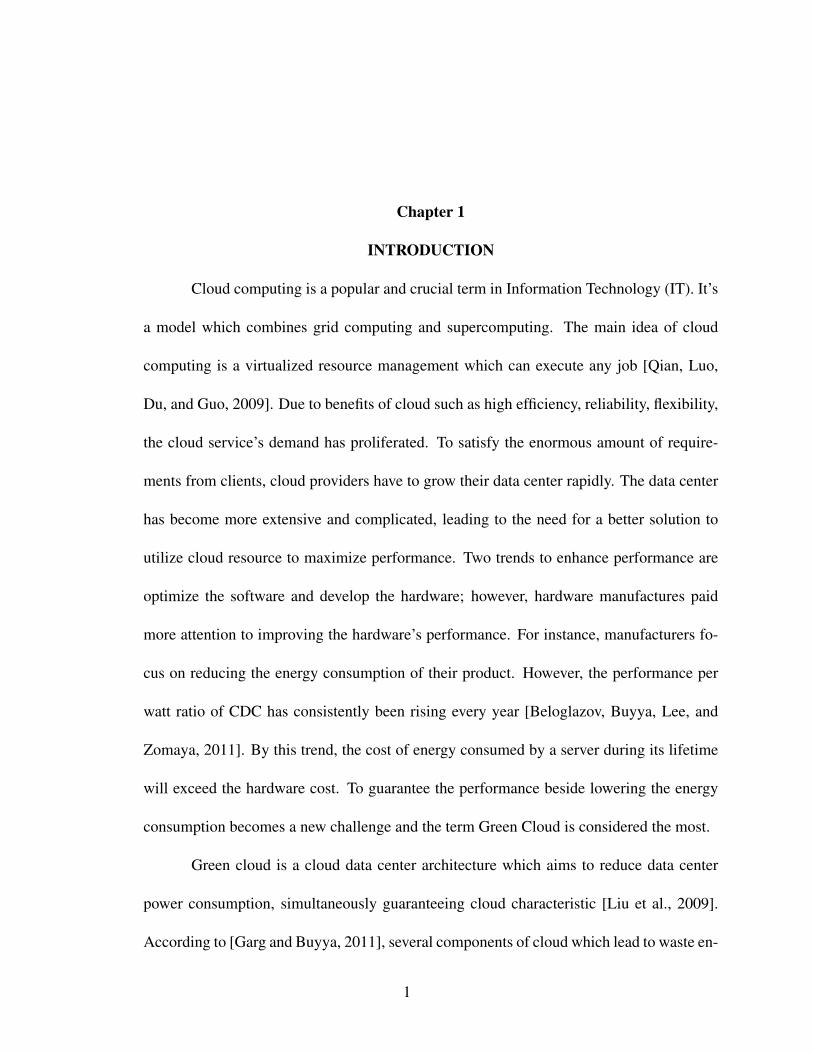
Cloud computing is a popular and crucial term in Information Technology (IT). It’s
a model which combines grid computing and supercomputing. The main idea of cloud
computing is a virtualized resource management which can execute any job [Qian, Luo,
Du, and Guo, 2009]. Due to benefits of cloud such as high efficiency, reliability, flexibility,
the cloud service’s demand has proliferated. To satisfy the enormous amount of require-
ments from clients, cloud providers have to grow their data center rapidly. The data center
has become more extensive and complicated, leading to the need for a better solution to
utilize cloud resource to maximize performance. Two trends to enhance performance are
optimize the software and develop the hardware; however, hardware manufactures paid
more attention to improving the hardware’s performance. For instance, manufacturers fo-
cus on reducing the energy consumption of their product. However, the performance per
watt ratio of CDC has consistently been rising every year [Beloglazov, Buyya, Lee, and
Zomaya, 2011]. By this trend, the cost of energy consumed by a server during its lifetime
will exceed the hardware cost. To guarantee the performance beside lowering the energy
consumption becomes a new challenge and the term Green Cloud is considered the most.
Green cloud is a cloud data center architecture which aims to reduce data center
power consumption, simultaneously guaranteeing cloud characteristic [Liu et al., 2009].
According to [Garg and Buyya, 2011], several components of cloud which lead to waste en-
1

ergy are user/cloud software application, network devices, and cloud data center including
cloud servers and supporting systems. This study will mainly focus on designing a cloud
data center architecture aimed to consume less energy without Service Level Agreements
(SLA) violation. Two concepts need to be explored: load balancing and load consolidation.
Based on the SLA, which is the contract between vendors and their customers set
up to ensure the Quality of Service (QoS), load balancing is an essential process which
redistributes the entire workload among compute nodes of the cloud cluster to optimize
resource utilization and improve the response time while avoiding a situation that existing
a overloaded server while another is underutilized or idle [Saranya and Maheswari, 2015].
One of primary resource utilization concept is to remove a condition in which some of
compute nodes have heavy workload while others are under load or in idle.
On the other side, the economic model of cloud computing is based on the pay-
as-you-go model, in which providing services by allowing users to design resources and
charge by what is used [Feller et al., 2012]. The challenge for providers is to create an
energy efficient method to handle all their services while meeting the SLA. This challenge
provides opportunities to investigate into load consolidation. The only way to reduce elec-
tricity consumption is consolidation processes which condenses the number of VMs run-
ning on physical compute nodes as much as possible and set idle inactive compute nodes.
Hence sluggish computers consume less electricity and generate less heat. The energy con-
sumption of the cooling system is reduced therefore power consumption of entire system
reduces significantly.
In data centers, the big challenge for a Green Cloud is to automatically make
scheduling decision between dynamically load balancing and consolidating VMs among
2

physical server to meet the workload requirements meanwhile saving energy. To accom-
plish the green cloud architecture, a system needs to trigger VMs migration and how to
select an alternative physical machine to locate VMs. Load balancing plays essential roles
in the management process, based on the capacity of each compute node. The system
will automatically reconfigure VMs placed in cloud clusters to ensure sharing the work-
load equally. Load balancing is often deployed in the peak hours when the requirement of
VMs rapidly rises. Cloud cluster consumes an enormous amount of electricity during peak
hours to satisfy the availability of the system. The other time, when client’s requirements
are lower, few compute nodes are running underutilized which leads to waste resources.
Load consolidation is implemented to save energy. Load consolidation collects the number
of VMs, and the capacity of each compute nodes to calculate and distribute VMs to the
smallest amount of physical servers then turn remaining servers to power save mode. VM
migration is a method to reverse load balancing state to load consolidation state and vice
versa.
In this study, we want to introduce our approach to reach the green cloud. In chapter
2, we briefly summarize the basic concepts related to cloud computing, green computing,
etc. Chapter 3 introduces the architecture which used to test the performance of our load
balancing and load consolidation algorithms. Chapter 4 brings forward the benefit of live
VM migration, and explains how it works. Chapter 5 and 6 open our contribution for load
balancing and load consolidation algorithm. Chapter 7 notes limitations of our approach
and opened suggestions for future work. The remaining chapters are the conclusion, ap-
pendix and references.
3

Chapter 2
BACKGROUND
2.1 Cloud Computing Concept
2.1.1 History
A distributed system is one computing paradigm invented in the early 1970s in
which its foundation is focused on networked computers. A distributed system can be de-
scribed as the combination of server resources in which all components communicate and
coordinate their action by passing messages [Shanmugam and Iyengar, 2016]. By having
this feature, all resources inside cloud clusters can access other resources for instance hard-
ware, software, network interfaces and data can be stored anywhere. It is controlled by
external devices which connect to the system to achieve transparency, fault tolerance and
scalability. One important function of a distributed system which increases its lifespan is
the capacity of controlling processes allowing implementation of a particular program on
different servers. Figure 2.1 is one example of the distributed system.
In the next computing generation of the early 1990s, grid computing was published.
The fundamental idea of grid computing is based on the distributed system. It is the collec-
tion of resources from multiple locations which are all interconnected to supply immense
computational power to solve a common goal [Shanmugam and Iyengar, 2016]. Com-
pared to distributed computing which is suitable only for small bounder applications, grid
computing improved on an interactive workload that affects a large number of files. Grid
4

Figure 2.1: Three bands used to classify PMs [Telkikar et al., 2014]
computing controls components which are loosely connected better, and supports func-
tions to network and process tasks from random locations. Figure 2.2 shows a model of
grid computing.
Figure 2.2: Model of grid computing [Shanmugam and Iyengar, 2016]
2.1.2 Cloud Computing Concept
Cloud computing s a model which combines grid computing and super-computing.
The main idea of cloud computing is a virtual server which can execute any job. The ori-
5
gin of the term cloud computing is ambiguous; the word "cloud" in science is commonly
related to a humorous object that appears very far from clients. Cloud computing concepts
emerged early as 1996 when mentioned in a Compaq internal document [Qian et al., 2009].
With the explosion of the Internet, the increase in customer’s demands created tremendous
pressure in existing data centers. Internet service providers began changing their orienta-
tion to the low-price commodity servers as an underlying hardware platform. According
to [Qian et al., 2009], in early 2006, the first cloud project named Elastic Compute Cloud
was introduced by Amazon. The fundamental technology of the Amazon cloud is server
virtualization. The second version of Amazon’s cloud emerged in 2010: Xen - based Elas-
tic Compute CloudTM (EC2) was released with much improvement over the first version.
Amazon also released others cloud services such as object storage service (S3) and Ama-
zon Web Services (AWS) which became the pioneer of Infrastructure-as-a-Service (IaaS)
provider. One strong competitor of Amazon is Google, starting earlier than Amazon. From
2003 to 2006, researchers from Google published several important research papers which
focus on Platform as a Service (PaaS) cloud computing. However, in 2008, Google in-
troduced the first cloud platform called Google App Engine TM (GAE). Due to the fast
growth of cloud computing, the giant technology company - Microsoft, joined the race of
developing cloud technology. Oct 2008, Microsoft AzureTM was released with Windows
Azure Hypervisor (WAH) as cloud infrastructure. Azure also supports object storage and
SQL service. Since 2008, cloud computing became a new trend in the computer industry
due to two reasons: one reason was because cloud computing could be implemented in
many scenarios, and the other was that lots of big companies supported it. According to
Hyper Cycle issued from [Cuccureddu, 2011], cloud computing was incredibly fast grow-
6

ing from 2008 to 2011 compared to other technologies invented in the same period. Figure
2.3 shows the growth of Cloud Computing compared to other technologies developed at
the same time.
Figure 2.3: Hyper Cycle in 2011 of Gartner Group. [Cuccureddu, 2011]
Cloud computing’s basic concept
Following the past, many definations of cloud computing were introduced, one
mentioned cloud which was a platform based on the internet to supply resource like ser-
vices, applications [Saranya and Maheswari, 2015]. Before going deeply for these cloud
computing features, we need to understand some basic concepts for instance virtualization,
hypervisor.
Virtualization - Concept and Benefit
In computing, virtualization is a generous perception related to the abstraction of
resources. According to Wolfgang Kellerer, [Khan, Zugenmaier, Jurca, and Kellerer, 2012]
this concept was first used when introducing the idea of time-sharing. At that time, IBM
7
Watson Research Center implemented a project named the M44/44X Project in which were
created virtual machines (44X) to image the real computer (M44). The project was a step
toward the implementation of virtual machine monitors which could generate multiple VMs
performing different operating systems. Only now, few decades after are we achieving
more success in virtualization, more functions, more efficient ways to generate and main-
tain VMs and PMs. The main achievement of virtualization was the implementation of
improving the way to use adequately available physical resources. Moreover, the concept
of isolation also implied in virtualization, which was either from the point of easy deploy-
ment, a collection of applications, or implements in application isolation or parallels at the
same time. Cloud computing also is a kind of virtualization service that using a network
of remote virtual servers hosted on the internet to provide shared processing resources and
data rather than a local server or a personal computer. All the processes of cloud comput-
ing such as collecting and performing resources are managed automatically. Nowadays,
cloud computing plays a significant role in a virtualization environment. Cloud computing
contributes a great combination of online resources including data storage, network, user
application, etc.
Hypervisors
In virtualization, virtual machine monitors, defined as hypervisors, are the low-
level programs in the middle of hardware and OS. The hypervisor allows users to run
multiple OSs on one PM in real-time. There are two types of hypervisors: type 1 and
type 2. Type 1 hypervisor is a thin layer of independence code interacting directly with
the hardware of the PM. This hypervisor provides working isolation environments for each
virtual machine, high performance, availability, and security. In type 2, the hypervisor is
8
controlled by the OS. It’s more convenient for users to implement and deliver the VMs to
any server. However, the security is the most concern issue when this type of hypervisor is
implemented.
There are five main hypervisors offered now which control 93% of the cloud com-
puting market [Botero et al., 2013]. Three closed-source are AWS, VMWare and Hyper-V
and two opened-sourced Xen and KVM. This study didn’t focus on closed-source impervi-
ous because of the limited permission on it, so Xen and KVM were the best architectures
to research. In this study, I use KVM as a hypervisor for my cloud cluster. Below is a
summary KVM’s construction trail [Botero et al., 2013] .
KVM is a relatively new open-source project dating back to Red Hat’s acquisition
of Qumranet in 2008. Its adoption has spiked since it was made part of the main Linux
kernel branch starting from version 2.6.20, becoming the primary virtualization package in
Ubuntu, Fedora, and other mainstream Linux operating systems. Each guest VM runs as a
separate user processes and has a corresponding QEMU device emulation instance running
with it. The difference between Xen and KVM is that KVM itself runs as a module inside
a host OS, which clarifies KVM as a Type-II (hosted) Hypervisor. Figure 2.4 describes the
architecture of KVM.
Cloud Computing Deployment Models
There are four deployment models applied in the cloud environment [Saranya and
Maheswari, 2015]:
• Public: The cloud infrastructure is provided in the public, which is opened for renting
over the internet.
9
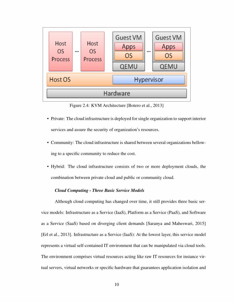
Figure 2.4: KVM Architecture [Botero et al., 2013]
• Private: The cloud infrastructure is deployed for single organization to support interior
services and assure the security of organization’s resources.
• Community: The cloud infrastructure is shared between several organizations bellow-
ing to a specific community to reduce the cost.
• Hybrid: The cloud infrastructure consists of two or more deployment clouds, the
combination between private cloud and public or community cloud.
Cloud Computing - Three Basic Service Models
Although cloud computing has changed over time, it still provides three basic ser-
vice models: Infrastructure as a Service (IaaS), Platform as a Service (PaaS), and Software
as a Service (SaaS) based on diverging client demands [Saranya and Maheswari, 2015]
[Erl et al., 2013]. Infrastructure as a Service (IaaS): At the lowest layer, this service model
represents a virtual self-contained IT environment that can be manipulated via cloud tools.
The environment comprises virtual resources acting like raw IT resources for instance vir-
tual servers, virtual networks or specific hardware that guarantees application isolation and
10
customize runtime environment. The hypervisor stays on top to manage resources. With
the IaaS model, the vendor will control virtualization, servers, storage, networking besides,
users are allowed to run their operating system, middleware, runtime, data, application.
The primary purpose of an IaaS model is to provide the highest level of flexibility and
management control over the cloud-based environment for consumers then they can design
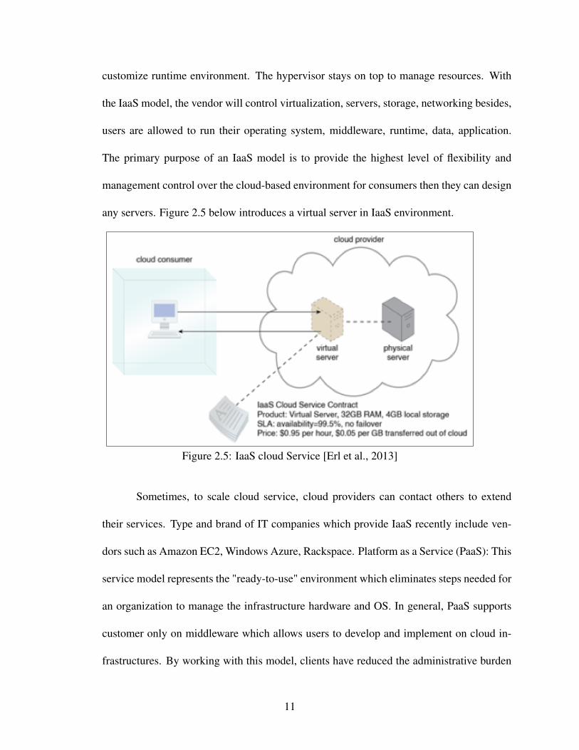
any servers. Figure 2.5 below introduces a virtual server in IaaS environment.
Figure 2.5: IaaS cloud Service [Erl et al., 2013]
Sometimes, to scale cloud service, cloud providers can contact others to extend
their services. Type and brand of IT companies which provide IaaS recently include ven-
dors such as Amazon EC2, Windows Azure, Rackspace. Platform as a Service (PaaS): This
service model represents the "ready-to-use" environment which eliminates steps needed for
an organization to manage the infrastructure hardware and OS. In general, PaaS supports
customer only on middleware which allows users to develop and implement on cloud in-
frastructures. By working with this model, clients have reduced the administrative burden
11
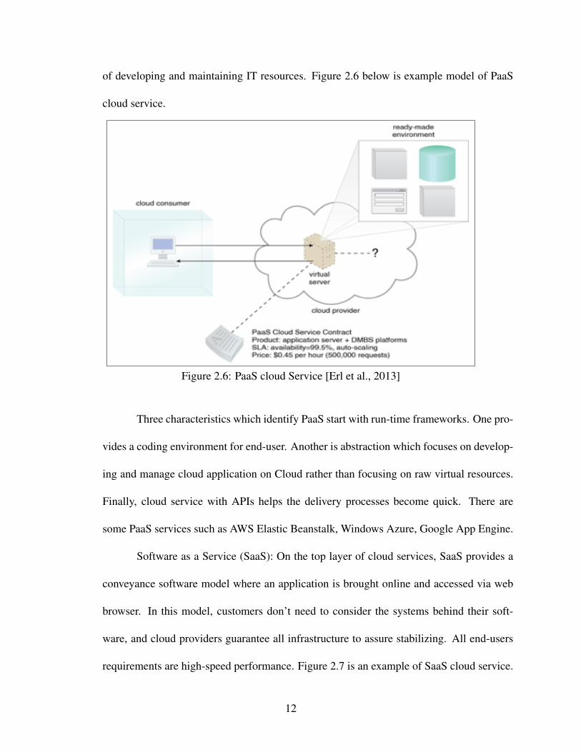
of developing and maintaining IT resources. Figure 2.6 below is example model of PaaS
cloud service.
Figure 2.6: PaaS cloud Service [Erl et al., 2013]
Three characteristics which identify PaaS start with run-time frameworks. One pro-
vides a coding environment for end-user. Another is abstraction which focuses on develop-
ing and manage cloud application on Cloud rather than focusing on raw virtual resources.
Finally, cloud service with APIs helps the delivery processes become quick. There are
some PaaS services such as AWS Elastic Beanstalk, Windows Azure, Google App Engine.
Software as a Service (SaaS): On the top layer of cloud services, SaaS provides a
conveyance software model where an application is brought online and accessed via web
browser. In this model, customers don’t need to consider the systems behind their soft-
ware, and cloud providers guarantee all infrastructure to assure stabilizing. All end-users
requirements are high-speed performance. Figure 2.7 is an example of SaaS cloud service.
12

Figure 2.7: SaaS cloud Service [Erl et al., 2013]
2.1.3 Cloud Computing Advantage and Disadvantage
Cloud computing advantage: [Korri, 2009]
Initial cost saving: One of the biggest challenge for companies or individuals when
launching a new product or service is initial cost [Korri, 2009]. Cost saving is classified into
two sides. One is the investment in the computer system, which includes hardware cost and
installation cost. Obviously, the cost of equipment rented from cloud computing provider
is much cheaper than the cost of investment in a new computer architecture. With cloud
technology, a huge investment in computer architecture is unnecessary. The other side is
cost upkeep used to maintain services. Using service from the cloud computing service
provider will reduce the cost of hiring IT personnel to support service. Furthermore, the
cost can be reduced based on the demand of companies or individuals because the rented
fee relies on the usage.
Flexibility: Cloud computing is more scalable than previous generations of com-
13

puting. According to usage, cloud computing platform can extend their capacity, which is
impossible to achieve the equal benefits of in other generations of computing without mas-
sive investment in infrastructure. In addition to scale up, users can scale down their service
which means a massive infrastructure might be cut off its capacity when a user does not
need a vast system behind their service.
Comfortable: When the responsibility of system infrastructures shift from users to
cloud service providers, this in turn reduces more burdens of users. They have no longer
have to worry about some issues raising during launching their service.
Available: With cloud computing technology, every member of organizations can
access their services in anywhere. Reasonable initial cost and deployment becomes easier
due to increase new business.
Cloud Computing Disadvantage[Korri, 2009]
Cost model: The model to calculate the usage’s price including customer’s usage
hour, data transfer and amount of storage is complicated.
There is no standard for all cloud providers so the process of moving data from one
cloud provider to another could be messed up. The customer should consider which cloud
provider is most suitable for their project.
2.1.4 Cloud Characteristics
Virtualization: All resources of the cloud are virtualized so it can achieve the vari-
ous types of software platforms or operating systems on one physical machine.
Service-oriented: This architecture model provides a system where all its compo-
nents are connected via the network and everything is represented like service.
Elastic: The cloud architecture allows cloud application to be dynamic provisioned
14
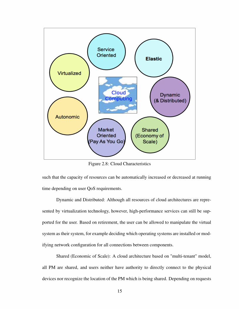
Figure 2.8: Cloud Characteristics
such that the capacity of resources can be automatically increased or decreased at running
time depending on user QoS requirements.
Dynamic and Distributed: Although all resources of cloud architectures are repre-
sented by virtualization technology, however, high-performance services can still be sup-
ported for the user. Based on retirement, the user can be allowed to manipulate the virtual
system as their system, for example deciding which operating systems are installed or mod-
ifying network configuration for all connections between components.
Shared (Economic of Scale): A cloud architecture based on "multi-tenant" model,
all PM are shared, and users neither have authority to directly connect to the physical
devices nor recognize the location of the PM which is being shared. Depending on requests
15

from users, load balancing or load consolidation algorithms are implemented to indicate
which physical device will trigger a VM to process the request.
Market-oriented (Pay-as-you-go): Price for using the cloud is calculated based on
pay-per-use (pay-as-you-go) model. The price is the diversified form of the quality of
service.
Autonomic: to guarantee delivery of dependable service to the customer, the cloud
services provide autonomic behaviors which auto-manipulates itself to prevent failure or
unanticipated cases.
2.1.5 Cloud Computing Components and Energy Usage Model: A Typical Example
Through a typical Cloud usage scenario [Garg and Buyya, 2011] , figure 2.9 de-
scribes a classic components of cloud computing services such as SaaS, PaaS or IaaS. In
this section, I will make analysis energy usage of a storage system which allows end-users
access and store their data on the internet based on cloud computing and energy usage
model.
Figure 2.9: Cloud Components [Garg and Buyya, 2011]
To activate cloud service, end users need to connect to the internet via their devices
16

and internet service provider. User’s data will be transfer to Gateway router within a Cloud
data center which will find the appropriate cloud data center to process the user requests.
Interior cloud data center, data goes through a local network to one virtual machine which
will process user data to connect to storage servers to response data back to end user. To
guarantee the quality of cloud service, some PMs are turned on to satisfy worst cases lead
to huge amount of energy consumption. Further, within cloud data center, there are many
devices which stabilize cloud system such as cooling, electrical device or consume power.
Besides, to assurance user data from losing, all cloud data centers have to design backup
servers located in a different location for recovering. All of those components of cloud data
center cause to incredible increment energy usage and associated carbon emissions.
Depending on cloud components some reasons may lead to waste energy:
• User/Cloud Software application: The way software application designed and imple-
mented can be one of the factors that cause to increment of energy usage. If these
software desire high performance in an extended period, the consequence of its ex-
ecution cause to high energy usage. Application inefficiencies as an example, sub-
standard algorithms of using shared resource lead to inappropriate resources usage
and, therefore, higher energy requirements. Additional, because of provision qualifi-
cation of cloud service, cloud provider always is designed to supply user demand in
the worst case, this means resources always provide more than the actual requirement.
Consequently, user software program in another way can contribute remarkable en-
ergy usage. However, most of the development applications are not estimate its power
capacity while designing.
17

• Cloud Software Stack for SaaS, PaaS, IaaS level: Cloud computing in another way
defined as a stack, which delivers a set of services built on top of the virtual machine.
When designing cloud service, providers have to guarantee Service Level Agreements
(SLA) which is a commitment to their customer on the qualification of duty. Besides
providing extra provision resources, cloud providers have to maintain their storage,
supply backup the storage to avoid failure, assure fast recover and reduce response
times. Therefore, it is necessary to discover the relationship between energy con-
sumption and SLA.
• Network devices: In cloud computing, when all resources are accessed through the
internet, therefore, both applications and user data desire much more communication
bandwidth between user’s computer to cloud data center. According to the energy
consumption estimation of ICT [G. and Edler, 2015], electricity usage of wired net-
work and WIFI network will continue expanding since it had in the past, until 2030,
in the worst case, energy usage of wires network and WIFI network might reach 7912
and 4529 (TWH). So network system is still involving in energy usage of the whole
cloud system. In some cases, transfer the significant data by post-office might be
cheaper and reduces more carbon emissions rather than using the internet. Because of
before data of end-user reaching data center, it has to pass many network devices, and
all data is aggregated in Ethernet switch devices then moves to many routers on the in-
ternet until it reaches its end point. Each of these network devices consumes a certain
amount of energy. Furthermore, [Garg and Buyya, 2011] total usage consumption
might be higher than expected to a great communication case. Therefore, with the
18
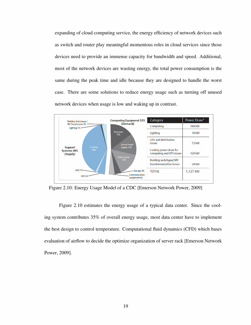
expanding of cloud computing service, the energy efficiency of network devices such
as switch and router play meaningful momentous roles in cloud services since those
devices need to provide an immense capacity for bandwidth and speed. Additional,
most of the network devices are wasting energy, the total power consumption is the
same during the peak time and idle because they are designed to handle the worst
case. There are some solutions to reduce energy usage such as turning off unused
network devices when usage is low and waking up in contrast.
Figure 2.10: Energy Usage Model of a CDC [Emerson Network Power, 2009]
Figure 2.10 estimates the energy usage of a typical data center. Since the cool-
ing system contributes 35% of overall energy usage, most data center have to implement
the best design to control temperature. Computational fluid dynamics (CFD) which bases
evaluation of airflow to decide the optimize organization of server rack [Emerson Network
Power, 2009].
19
2.2 Green Cloud Computing
2.2.1 Green Computing
Green Computing (also called green information technology or the Information and
Communications Technology (ICT) sustainability) can be described as a study of design-
ing, deploying computer resources such as servers and associated subsystem such as mon-
itors, network devices to less impact on the environment [Raza et al., 2012]. The primary
goal of green computing is to cut down or minimize materials which are wasting energy.
The other is to endeavor to accomplish economic feasibility and improved system perfor-
mance.
2.2.2 Some Solutions to Reach Green Computing
Sometimes, solutions to the critical issues started from simple principles. Best work
habits of computer administrators and users can help to minimize the impact of computers
on the global environment. Here are some patterns that can be taken [Agarwal and Nath,
2011].
• Virtualization: Concerning virtualization, many studies which indicate that with vir-
tualization, the data center can offer significant energy and cost saving [Alzamil, Dje-
mame, Armstrong, and Kavanagh, 2015].
• Processor consumes 15% energy of total based on the analysis above. So, using more-
efficient processors is critical energy saving factor.
• Setting the power options of a computer to switch to sleep mode when it’s idle.
• Tasks divide.
20

• Use computer parts which performance efficiency energy such as: using the flat mon-
itor than CRT, avoid screen saver.
The advantages of green computing such as reduces overall energy consumption lead to
decrease electricity costs, optimize performance, recycle end-of-life equipment, etc. with
the rapid growth of cloud computing, increasing data centers which include cooling sys-
tems, equipment power density cause the new trend in cloud computing industry: the green
cloud.
2.2.3 Green Cloud
Cloud computing, next generation of computing era, a platform that based on the
internet to supply resources like services and applications, has more influence on IT indus-
try. Due to benefits of cloud mentioned above, cloud service’s demand has snowballed.
To satisfy an enormous requirement from clients, cloud providers have to grow their data
center. The data center has become bigger and more complicated. Therefore green cloud
model has become the most current concern. Although manufactures paid more attention to
improving the hardware’s performance such as reducing the energy’s consumption of their
product, however, the performance per watt ratio has consistently been rising every year
[Beloglazov et al., 2011]. By this trend, the cost of energy consumed by a server during
its lifetime will exceed the hardware cost. The problem is even worse for the large system
such as cluster or data center.
Green cloud is an internet data center architecture which aims to reduce data cen-
ter power consumption, while at the same time guarantees cloud characteristic [Liu et al.,
2009]. To achieve green computing goals, based on factors which lead to waste energy
21

mentioned in the chapter above, the process to reach green cloud is classified into three
main majors: user applications, network systems, data centers. This study will mainly
focus on designing data center which contributed the most energy consumption with virtu-
alization solutions to achieve green cloud.
In the data center, the big challenge for a Green Cloud is to automatically make
scheduling decisions between dynamically load balancing and consolidating VMs among
physical server to meet the workload requirements meanwhile saving energy. To accom-
plish the green cloud architecture, several keys are related including when a system needs
to trigger VMs migration and how to select an alternative physical machine to locate VMs.
Those two concepts are applied in load balancing and load consolidation algorithms, which
are two powerful strategies to achieve Green Cloud. Load balancing plays essential roles
in the management processes, based on the capacity of each compute node, the system will
automatically reconfigure VMs stored in the cloud cluster to ensure sharing the workload
equally. There are no overloaded compute nodes while the others are idle or underutilized.
Load balancing is often deployed in the peak hours when the VMs requests rapidly in-
creases. Cloud cluster consumes an enormous amount of electricity during peak hours to
satisfy the requirement of the system. The other time, when client’s request are lower, few
compute nodes are running underutilized leading to wasted resources. Load consolidation
is one of a powerful solution to save energy. Load consolidation collects the number of
VMs, and the capacity of each compute nodes to calculate and distribute VMs to the small-
est number of physical servers. Then, turns the remaining servers to power save mode. VM
migration is a method to reverse load balancing state to load consolidation state and vice
versa.
22
2.2.4 Feature of Clouds Enabling Green Cloud
According to [Accenture Microsoft Report, 2010], there are some features of cloud
which can turn to the green cloud.
Dynamic Provisioning: In enterprise computing, the data centers are designed to
handle the worst case. Therefore, technology companies have to invest in more equipment
than needed. There are two main reasons for such provisioning: It is too hard to predict
the usage in the future, most of the companies don’t want to upgrade their system monthly
or annually. They want their infrastructure can afford the market around five years. Ad-
ditionally, the new server has to guarantee the level of quality to end user all the times.
Website servers are an excellent example of energy efficient. Website host have to provide
the high performance in both worst case and idle. This issue becomes simple with cloud
service, when a cloud provider can extend their service by making a contract with the web
hosts, among others to assure the quality. Thus, data centers only need to maintain current
demand without considering over provisioning.
Multi-tenancy: One benefit of cloud services which improve adequate using re-
sources of enterprise servers. Hardware today has much more power than before, because
device manufactures have continuously upgraded their products. With virtualization, all
resources can both be shared between server tenancy and isolated data leads to a decrease
in energy consumption.
Server Utilization: In general, traditional servers typically don’t use more than 90%
of their capacity. With virtualization, data in each computer node can quickly move to other
nodes based on VM migration technology. Thus, all unused compute nodes can be turned
23
off or switch to low power mode to conserve energy. Those dynamic processes improve
the utilization levels up to 70%.
Data center efficiency: As discussed before, the data center is a major factor which
impacts energy usage of whole cloud system directly. By cutting down underutilized com-
puter nodes, support system, consisting of network systems, cooling systems, which con-
tribute half of the total energy usage of the data center„ also is cut down too. Additionally,
virtualization allows moving data between two data centers which provides high speed for
end users by moving their data to the closest data center.
2.2.5 VM Migration
Virtualization recently has become a new trend in computing, due to their structure
where all hardware resources are shared over a network to optimize resource utilization.
VM migration process, technique, which migrates a VM between hypervisors or physical
hosts with purposes such as improving the system performance. There are two kinds of
communication mode: live and non-live migration. Live migration allows migrating a
running VM from one physical host to another without disrupting service. It means that
users will not recognize the movement of their VM between physical host while using the
system. This approach helps to improve the continuity and availability of the service. Non-
live migration, in contrast, does not support this feature. To migrate, VM should be turned
off, then resumed after completing the migration processes.
From [Ahmad et al., 2015]. summarizes in details the applications of VM migration
discussed below:
• Power management: For server consolidation, by VM migration, the head node which
24

controls the whole cloud cluster migrates all VMs into a certain number of physical
hosts without reducing performance or existing any overload physical hosts. The
remaining physical hosts are turned off to reduce in a significant amount energy con-
sumption.
• Resource sharing: The issues when sharing limited system resource can vary the sys-
tem performance. It can be solved by VM migration when migrating a "hungry" VM
to a resource-rich server.
• Fault tolerance: The fault-tolerant system prior interrupts system to handle the failure
happening. VM will be migrated back to the original physical host if the destination
host failures for some reasons.
• System maintenance: To support the system performance, maintenance processes are
frequently implemented during the server time life. All VMs are migrated from the
hosts which are under maintenance schedule to the other.
• Load balancing: This application helps the cloud system to avoid failure of a single
host cause of heavy workload when existing a light workload host. VMs from the
heavy workload physical host migrated to another which is a light workload.
• Mobile computing: Today, people do not prefer to work on their desktop or laptop
only. Rather, due to the proliferating of smartphone or tablet, people want to work on
these devices which are more flexible when moving. Migration application helps to
migrate the workload from operating system of a smartphone to a desktop server or
vice verse.
A taxonomy of VM migration schemes
25

This section highlights and discusses how we classify the current VM migration
schemes. Due to [Ahmad et al., 2015], VM migration pattern divided into seven categorizes
migration pattern, objective function, network link, hypervisor type, execution resources
constraints, migration granularity, network management.
VM migration pattern mainly focuses on the method which uses to migrate VM
between two servers. A cloud data center recently implemented two methods which are live
VM migration and non-live VM migration. As discussed above, live migration is a process
in which migrating a running VM between two hosts without any interruption. In contrast,
non-live VM migration requires to shutdown VM before migrating processes. Additionally,
live VM migration has three categories which are pre-copy VM migration, post-copy VM
migration, and hybrid methods. Pre-copy VM migration mode transfers entire memory to
the destination host to low the dirties pages before pausing VM for migration. The method
tried to minimize downtime during VM migration process due to rising the network traffic.
On the other hand, post-copy VM migration has a better solution to reduce data transfer via
the network and optimize the total movement time, but the downtime is much higher than
pre-copy VM migration. The hybrid method is the combination of both schemes above.
Objective functions which are using to evaluate migration algorithms including:
• Minimizing downtime which is the period of the time when a VM is down for migrat-
ing and the time when the destination host can resume that VM. All VM migration
algorithms aim to optimize downtime to guarantee the performance.
• Minimizing the migration duration which is the time when VM starts to migrate until
completing the entire VM migration processes.
26

• Reducing the length of application QoS degradation.
• Optimizing the bandwidth: Although migration is the useful feature, however, it’s still
an expensive process which mainly based on network bandwidth.
• Network protocol: The metric which specifies the type of network protocol chose
to migrate VM. LAN is still a better option to migrate VM in data center due to
the stabilizing of bandwidth and connection. WAN attribute, in contrast, has limited
bandwidth.
• Hypervisor type: There are so many companies developing their type of hypervisor
which outputs with a different feature of migration such as XEN, KVM, VMWare,
etc.
Under execution resource constraints metric, VM migration delivers into two forms:
shared and dedicated. Under migration granularity metric, VM migrations grouped into
single migration processes or multiple migration processes happened at one time. The other
metric is network management which classifies VM migration following ARP (address
resolution protocol), virtual private network (VPN), mobile IP, IP tunneling, and dynamic-
DNS.
When do the cloud clusters need load balancing process?
Load balancing in cloud computing supports a robust solution to setup condition
of system’s structure. Two primary goals of load balancing are resource provisioning and
scheduling in the distributed environment [Raza et al., 2012]. VM migration is one excel-
lent method to deploy load balancing. Figure 2.11 is an example of load balancing using
VM migration. Depending on the requirement and information collecting from physical
27
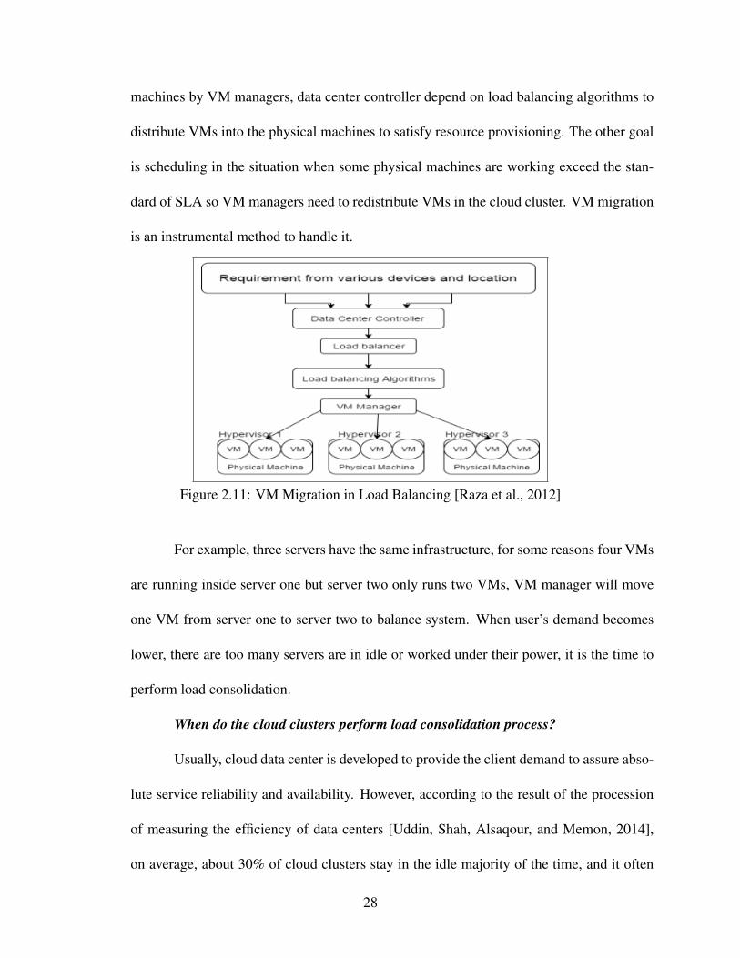
machines by VM managers, data center controller depend on load balancing algorithms to
distribute VMs into the physical machines to satisfy resource provisioning. The other goal
is scheduling in the situation when some physical machines are working exceed the stan-
dard of SLA so VM managers need to redistribute VMs in the cloud cluster. VM migration
is an instrumental method to handle it.
Figure 2.11: VM Migration in Load Balancing [Raza et al., 2012]
For example, three servers have the same infrastructure, for some reasons four VMs
are running inside server one but server two only runs two VMs, VM manager will move
one VM from server one to server two to balance system. When user’s demand becomes
lower, there are too many servers are in idle or worked under their power, it is the time to
perform load consolidation.
When do the cloud clusters perform load consolidation process?
Usually, cloud data center is developed to provide the client demand to assure abso-
lute service reliability and availability. However, according to the result of the procession
of measuring the efficiency of data centers [Uddin, Shah, Alsaqour, and Memon, 2014],
on average, about 30% of cloud clusters stay in the idle majority of the time, and it often
28
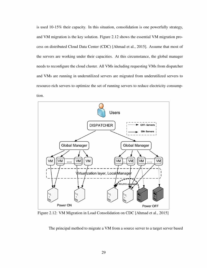
is used 10-15% their capacity. In this situation, consolidation is one powerfully strategy,
and VM migration is the key solution. Figure 2.12 shows the essential VM migration pro-
cess on distributed Cloud Data Center (CDC) [Ahmad et al., 2015]. Assume that most of
the servers are working under their capacities. At this circumstance, the global manager
needs to reconfigure the cloud cluster. All VMs including requesting VMs from dispatcher
and VMs are running in underutilized servers are migrated from underutilized servers to
resource-rich servers to optimize the set of running servers to reduce electricity consump-
tion.
Figure 2.12: VM Migration in Load Consolidation on CDC [Ahmad et al., 2015]
The principal method to migrate a VM from a source server to a target server based
29

on two categorized of VM migration pattern live VM migration and non-live VM migration.
Figure 2.13 shows VM migration pattern-based taxonomy.
Figure 2.13: VM Migration Pattern [Ahmad et al., 2015]
• Live VM migration provides uninterrupted services during VM migration time via
three categories: Pre-copy VM migration, Hybrid Method, and Post-copy VM migra-
tion.
• Pre-copy VM migration: the iterative process of copying VM memory pages from
source servers to target servers until reaching some termination criterion.
• Post-copy VM migration: the process separated into three phases. In the first, VM
execution at source server is suspended then turns to the minimum state to transfer to
the target server. The second phases, VM is resumed in the target server. Finally, the
memory from source server is copied to target server.
• Hybrid method: the combination of both pre-copy and post-copy method. Non-live
VM migration discontinued implementing cause to the advantage of live VM migra-
tion. At target server, VMs will not be resumed until completing the migration process
lead to degrading the Quality of Service.
30
When the user’s demand suddenly rises during rush hours, by VM migration process, cloud
cluster automatically turns from load consolidation to load balancing to guarantee the Qual-
ity of Service.
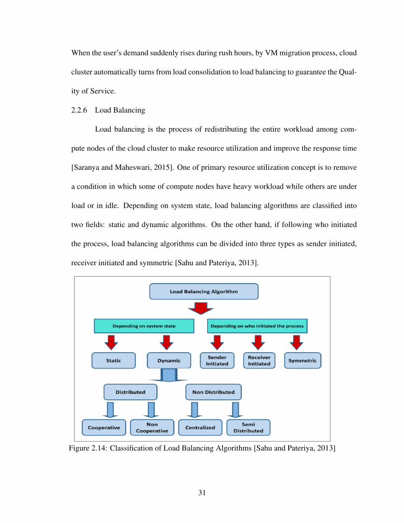
2.2.6 Load Balancing
Load balancing is the process of redistributing the entire workload among com-
pute nodes of the cloud cluster to make resource utilization and improve the response time
[Saranya and Maheswari, 2015]. One of primary resource utilization concept is to remove
a condition in which some of compute nodes have heavy workload while others are under
load or in idle. Depending on system state, load balancing algorithms are classified into
two fields: static and dynamic algorithms. On the other hand, if following who initiated
the process, load balancing algorithms can be divided into three types as sender initiated,
receiver initiated and symmetric [Sahu and Pateriya, 2013].
Figure 2.14: Classification of Load Balancing Algorithms [Sahu and Pateriya, 2013]
31

According to [Hans and Kalra, 2015], based on user demand, there are some mea-
surement parameters to evaluate the load balancing algorithms which are discussed below.
• Throughput: the system can process an amount of a given input in certain of time.
• Response time: It is an amount of time used to execute the user query.
• Fault tolerance: It is the ability that allows the system keep working precisely even
any failures are happening.
• Scalability: It is a capacity to expand itself according to required conditions.
• Performance: How the load balancing concept affects the system performance such
as reducing the electricity cost, the speed of task execution.
2.2.7 Load Consolidation
The economic model of cloud computing based on the pay-as-you-go model in
which providing services by allowing users to design resources and charge by what is used
[Feller et al., 2012]. The challenge for providers is to create an energy efficient to handle
all their service while meeting the Service-Level Agreement (SLA) which is the contract
between vendors and their customers set up to ensure the Quality of Service (QoS). On the
other hand, because of the benefit of cloud computing, the growing client demand has led to
the cloud provider to increase their data center. This tendency has resulted in huge electric-
ity consumption. The only way to reduce electricity consumption is consolidation process
which migrates virtual machines on a certain amount of physical compute nodes as much
as possible and set idle compute nodes in power saving state. Hence not used computers
consume less electricity then generating less heat, the energy consumption of the cooling
system is reduced then power consumption of entire system reduces significantly. Consol-
32

idation based on live migration, a technique allowing migrating running virtual machines
without rebooting operating system inside it. There are three categories of consolidation
managers: static and semi-static and dynamic [Han, Que, Jia, and Shu, 2016]. In static
consolidation, VMs are expected to live in the host for a long-time period until it has been
touched. In semi-static consolidation, live migration is used for creating a cycle of VM
migration process in a daily or weekly. Resource utilization of both static and semi-static
do not change during execution, the number of reconfigurations according to the process of
creation and deletion of VMs. Dynamic consolidation is a possible technique that allows
the VM migration would occur at every moment. The figure 2.15 shows four classical steps
of load consolidation: monitoring, estimation, reconfiguration and actuation [Feller et al.,
2012].
Figure 2.15: Load Consolidation Steps [Feller et al., 2012]
2.3 Related Work
Live migration is a useful technique, but it’s still costly and time-consuming, which
affects the network performance due to the whole process performance based on network
bandwidth. Task-based system load balancing algorithm in cloud computing uses particle
swarm optimization which is a new load balancing idea introduced by [Ramezani, Lu, and
Hussain, 2014]. The work aims to reduce the downtime, which is a period of time when
33

a VM is paused from the original host until it is resumed in destination host by migrating
extra tasks from overloaded host to underutilized host. The pre-copy VM migration is
unnecessary in this approach to eliminate the downtime. However, due to unpredictable
incoming tasks to cloud data center, the extra task is hard to control when the system
becomes more complex. Otherwise, the system has to find another compatible VM to
execute the extra tasks from the overloaded host, which requires building some similarity
VMs, and leads to resource wastes such as space of cloud resource.
One of the main challenges of load balancing is it is required to evenly distribute
workload across multiple PMs to boost performance and avoid the situation in which two
machine exists simultaneously. One machine is executing overloaded tasks when the other
is in idle mode or is performing under its capacity [More and Mohanpurkar, 2015]. Par-
titioning concept is introduced in this work to provide a switch mechanism for choosing
different strategies for various situations. The approach applies centralize strategy, which
is used in a central machine to gather data then distribute the workload to other partitions.
In our approach, we are also using head-node that dynamically receives the request from
clients then distributes those requests evenly to every running compute node. The advan-
tage of this strategy is to balance the load between n number of compute nodes before
triggering live VM migration processes to optimize CPU’s usage of cloud cluster.
Kao et. al [Kao, Cheng, and Kao, 2014] also publish their work on an automatic
decision-making mechanism for live VM migration. They present a schema to decide when
the system needs to balance workload to guarantee the performance and when it needs a
consolidation strategy to utilize energy consumption. Their system will trigger VM mi-
gration based on the CPU’s usage. However, 80% of CPU’s usage which is fixed to make
34

VM migration decisions might be due to the waste of the resource when the hardware is
more powerful today. In addition, because of the fluctuating of CPU’s usage during running
time, the CPU’s usage can go up to 100% in a second then down to 1 - 2% quickly. Their
scheme should set up a time to calculate the average of CPU’s usage before triggering VM
migration.
Figure 2.16 is an example of Green cloud architecture [Liu et al., 2009]. Authors
of this structure want to design the power efficiency and effectiveness for online gaming
applications hosted in data center environment, achieved by live migration technology. Mi-
gration manager triggers live migration and decides on the placement of virtual machines
on physical servers based information provided by the Monitoring Service. The Moni-
toring Service measures including application workload, resource utilization, and power
consumption, hence the system can dynamically adapt workload and resource utilization
through VM live migration. The Migration Scheduling Engine searches the optimal place-
ment and sends an instruction to execute the VM migration and turn on or off a server.
Based on this architecture, unnecessary power consumption in this cloud computing envi-
ronment is reduced significantly.
35

Figure 2.16: Green Cloud Architecture [Liu et al., 2009]
36

Chapter 3
PROPOSED ARCHITECTURE
3.1 Architecture
A distributed computer system is a set of connected computers that work together
in such a way that they could be viewed as a single system. Clustering is mainly used
for parallel processing, load balancing, and fault tolerance. Our proposal will be relatively
easy to add more power to the cluster by simply adding a new computer to the network.
According to [Cisco, 2008], the architecture of server cluster normally consists of a master
node which manages other compute nodes. Figure 3.1 is an example of a typical server
cluster. The cloud architecture in this study aims to optimize the performance and reduce
energy consumption of one cloud cluster in the whole cloud data center. This architecture
can be implement in multiple cloud clusters to utilize cloud data center. Applying the
similar architecture above, there are three main components in this project: head nodes,
storage node and compute nodes.
• Head node: An administrative interface for accessing cloud administrative feature
and virtualized resources. It is a connection between VM requirements from users
and cloud cluster. It assigns the VM’s requests to each compute node based on the
load balancing algorithm. It also acts as a bridge between compute nodes when the
load consolidation is needed.
• Storage node: nodes used to store persistent user data and VM images. These nodes
37

Figure 3.1: Logical View of a Server Cluster [Cisco, 2008]
can replicate data to backup devices to keep data availability high. Otherwise, storage
node stores VM images which are launched by compute nodes.
• Compute node: nodes that provides the execution environment for virtual machine
instances in Green Cloud. These nodes provide IaaS resources with the help of the
KVM hypervisor and Virsh system tools, and can be dynamically scaled based on cur-
rent demand. Compute nodes have a large capacity computing, so the load balancing
and load consolidation algorithm will improve performance more effectively.
Figure 3.2 is an example of our test cloud environment.
3.2 Network Filesystem
Since a shared network is a requirement for implementing live VM migration a re-
search of all network filesystem technique is necessary. In this study, we used "glusterfs"
38

Figure 3.2: My Network Cloud Cluster
an open source which is a scalable network filesystem suitable for data-intensive tasks such
as cloud storage and media streaming to perform our cloud environment [Readthedocs.io,
2017]. The concept brick in Glugterfs is defined like any directory on underlying disk
filesystem. In GlusterFS, a volume is a combination of bricks from a PM or vary PMs.
Glusterfs has five types of volumes which are distributed glusterfs volume, replicated glus-
terfs volume, distributed replicated glusterfs volume, and striped glusterfs volume. In this
research, we implement the distributed glusterfs volume architecture which is the default
of glusterfs volume. Files are distributed across various bricks in the volumes in this ar-
chitecture. The set of bricks includes all redundant spaces in all PMs of our cloud cluster
consisting of the head node, storage node, and compute nodes. Following this architecture,
39

the size of cloud cluster easily scales and speed up. This architecture fit on our research
when we aim to optimize a cloud cluster unit in the entire CDC. Although, if a brick fails for
a reason, this will lead to complete loss of data, cloud provider always has backup servers
to handle a failure to guarantee the QoS. Figure 3.3 is an example of a typical server using
distributed volume for the network filesystem.
Figure 3.3: Distributed Volume in Glusterfs [Readthedocs.io, 2017]
40

Chapter 4
LIVE VIRTUAL MACHINE MIGRATION
In this project, I focus on live migration - the method which is moving running VM
between two hosts without interrupting the service. Today, there are three kinds of live VM
migration including pre-copy VM migration, post-copy VM migration, and hybrid which is
the combination of pre-copy and post-copy. Pre-copy is a popular method is using recently.
4.1 Pre-copy VM Migration
According to [Song, Liu, Yin, and Gao, 2014], source host first transfer all memory
pages to a destination except dirty pages which are being modified by VM or user. Those
pages will be transferred during downtime - the period when VM is paused to migrate. This
approach aims to minimize downtime, and the migration process will happen as soon as the
number of dirty pages is small. Live VM migration developed by KVM followed this idea
consists of 5 steps [Mukhedkar, Chirammal, and Vettathu, 2016]. To deeply understand
this approach, I’ll point out the main idea of each step below:
Step 1: Preparing the destination: At the beginning of live migration process, after
the system determines which host needs to migrate VM and another will receive it, libvirt
of source host will try to communicate libvirt of the destination host. After the connection
is established, standard information of VM which is going to migrate is transferred to the
target host. All information will be passed to QEMU to prepare for enabling migration.
Step 2: Transfer the VM: In pre-copy, it doesn’t transfer the whole VM at one time,
41

only the parts that are missing at the destination are transferred such as the memory and
state of VM. On the other hand, all stuff such as the virtual disk, the virtual network, etc.
are available to sync in the destination host. QEMU controls the moving data processes.
During this step, the VM is still running on the source host, and the clone is paused. When
transferring the memory, the system tries to pass the full memory from the source host to the
destination host. Once the most memory is on the target host, QEMU starts transferring the
dirty pages of memory which have just been modified by running VM and haven’t written
yet to the disk. For the running VM, the dirty pages always are there and are modified
continuously. There is no way to transfer all dirty pages without pausing the VM. This
state will stop until the number of dirty page reaches a low threshold (50 or less) then the
system moves to next stage.
Step 3: Stop the VM at the resource: At this step, the VM at source host is paused.
The synchronous process is triggered at the destination host. Downtime is the period it
takes from this stage until the VM is resumed.
Step 4: Transfer VM state: At this step, all the remaining dirty pages will be moved
to the destination host as soon as possible without any limitation of network bandwidth.
Step 5: VM continuation: VM on the target host is resumed. The changing is
virtual NICs, and the bridge sends to the network to update hypervisor. After receiving an
announcement, data for that VM is passed to the new VM on the destination host. When
the whole VM is at destination host, live VM migration is total completed.
4.2 Live VM Migration supported by KVM
To applying live VM migration feature, few requirements needed to be considered:
42

• The cloud cluster needs to have a shared storage which hosted all VM images using
one of the following protocols: iSCSI, NFS, GFS2, FCoE, etc. Our approach uses
GFS2 protocol which we discussed in the previous chapter.
• The migration platform and version should be checked the compatibility.
• Both source PM and target PM must have the appropriate TCP/IP ports open.
• A shared storage must mount at the same location on the source and the target server.
After setting up the environment, a guest VM from source PM can be migrated to
another host PM with the "virsh" command: virsh migrate−−live GuestName DestinationURL.
When a guest name is the domain name of VM and Destination URL can be the IP ad-
dresses or the name of that PM in the/etc/ hosts file.
43

Chapter 5
DYNAMIC LOAD BALANCING
The motivation of this chapter came from our previous project which was Topper
Cloud. The main idea of that project was to provide a virtual lab which could access via
web browser. Virtual lab copied all feature from the traditional labs which installed all
necessary software for students during college. Instead of going to the lab for research or
study, due to the project, students felt more convenient to access to the lab any time or
everywhere they want. The project received a lot of good feedback from students except
the quality of service because we didn’t have proper solutions to design the cloud data
center to optimize the performance as well as reduce the energy’s consumption to reach
the green computing concept. Get a motivation from this, this contribution chapter and
the next chapter are our approaches to enhance the server. The following in this chapter
are three functions of the load balancer to increase the performance. We also provide the
implementation and particular test cases based on the workload simulation to verify the
approach.
5.1 Dynamic Load Balancing
Load balancing in cloud computing supports a powerful solution to reach a con-
dition of system optimization. Two main goals of load balancing are scheduling in a dis-
tributed environment and resource provisioning [Telkikar et al., 2014]. Scheduling handles
the distributed workload from user requests to every PM in cloud cluster and balances
44

CPU’s usage to increase the system performance. Resources provisioning is to guaran-
tee the quality and availability of cloud service by turning on some PMs to handle extra
requests in case all running PMs are nearly overloaded.
5.1.1 Distributed Workload
Based on the request VMs from clients, the head node, a server which manages the
whole cloud cluster will calculate itself to distribute the whole VM requests to all running
computer nodes depending on the capacity and the number running VMs in each computer
node. There are few logical steps to be applied in the head node, algorithm 1. First, the
controller of the head node will distribute equally VM requests to each PM. Based on the
capacity pull out from the database, each PM will try to execute as much as it can the
requests. The number of lacking will be sent back to the controller and to be distributed
to others in next iteration. After calculating exactly the number of VMs for each PM, the
head node will send instantaneous VM requests to all compute nodes at one time. In case
all running servers can not handle all the request from clients, the head node needs to turn
45

on other machines to execute the remaining VM request. Wake-up signals from the head
node are sent to servers which are in the save mode. Those servers will be active quickly
then post an update data back to the head node. After updating the data of the new server
into the database, the head node will send the remaining request to those servers. The detail
of those processes we will discuss in the section.
5.1.2 Optimize CPU’s Usage
The cloud centers are mostly constituted from heterogeneously servers, which con-
tain a different number of VMs due to fluctuating resource usage. This problem causes to
imbalance resource and degrades the performance [Xu, Tian, and Buyya, 2017]. To achieve
efficient resource utilization, optimizing CPU’s usage of the whole cloud data center is the
most challenger for every load balancing algorithms. There are a lot of researchers who
focus on this area but most of them do not apply the benefit of live VM migration. Dy-
namic load balancing which was introduced in [Telkikar et al., 2014] takes more advances
than the other. In our approach, the goal is to automatically migrate VMs from one node
to others to assure that the workloads on every node are equal or closer. Two primary steps
are implemented in this feature consists of: Calculate the load classification and create a
migration decision plan.
5.1.2.1 Calculate the Load Classification
The head node will send messages to all running compute nodes to require the
CPU utilization. After collecting all data, the controller in the head node will calculate the
threshold based on those data to classify all PMs. Next step, the controller will determine
the mean by taking the highest CPU utilization subtract the lowest one then dividing the
result by two. The difference between the threshold and the mean is used to define the light
46

and the heavy threshold. Based on light and heavy threshold, the controller classifies the
CPU utilization of all PMs into three bands, figure 5.1 and algorithm 2.
• Moderately loaded range is calculated based on adding or subtracting the values which
are the difference between the average (L(avg)) and the mean of maximum and mini-
mum to the average.
• Lightly loaded is on the left-hand side of light threshold and heavily loaded is on the
right-hand side of heavy threshold.
Figure 5.1: Three bands used to classify PMs [Telkikar et al., 2014]
47

5.1.2.2 Migration Policy
After calculating three bands and classifying all PMs, the system won’t change if
all PMs belong to the moderately loaded group. Otherwise, migration is triggered when
existing at least two PMs: one belongs to the lightly loaded group, and the other belongs
to the heavily loaded group. Assuming that the server requires to trigger load balancing for
some reasons. There are two considering of load balancing processes in this feature which
are: one is to determine a list of PMs which need to migrate its VMs (list 1) to a list of PMs
which receive VMs (list 2). Second is to determine which VMs of a PM in the list 1 to PM
in the list 2.
Algorithm 3 outlines the idea of our approach choosing the source PM and target
PM in the following order. The controller will calculate two parameters which are "the total
need" and "the total free" based on comparing the threshold with all PMs in list 1 and list 2.
The total needs is a sum of all needs which are the workload of CPU utilization needed to
migrate to reach the threshold. In contrast, the total frees is a sum of all frees which are the
space between the CPU utilization of PM in list 2 and the threshold. A loop is implemented
to migrate some VMs in PMs of list one to PMs of list two following order. In other words,
the algorithm will choose PMs from the top to the end of list one to migrate its workload to
all PMs in the list two by order. Two cases can happen: a PM in list one migrate to multiple
PMs in list two, or a PM in list two receives migration data from various PMs in list one.
The loop ends when either total need or total free equal to zero.
After identifying a pair of PMs which need to migrate data and which receives those
data, the next consideration is to determine the set of VMs are necessary to be migrated. In
48

other words, with a specific workload of each PM in list one, the PM needs to determine the
best set of VMs of it to migrate which the sum of it is the closest to the workload discuss
above. Algorithm 4 is our approach to solve this requirement. The first step, the controller
will sort the collection of CPU utilization from high to low. Next, a "while" loop is called
to scan the list from left to right. In the scenario that the "need" is higher than the virtual
CPU utilization of VM so that VM will be added to the migration list and calculate the new
"need" by subtracting the need to the virtual CPU utilization. The loop halt when the need
is equal to zero or it lesses than lowest virtual CPU utilization which means that this PM
does not need to migrate any VMs to reach the threshold. Additionally, the method accepts
49

to migrate a VM which has virtual CPU utilization higher than the "need" 5% to handle the
unstable of CPU. For instance, a PM needs to migrate 10%, but the lowest virtual CPU’s
usage is 15%, the migration policy accepts to migrate in this scenario.
5.1.3 Resource Provisioning
The load balancing algorithm may need to handle two extreme scenarios: One,
for some reasons some VMs suddenly receive a heavy workload lead to rising quickly
CPU’s usage of the PM up to the high performance and stays there for a period of time.
To guarantee the quality of service, the PM needs to communicate with the head node
(the controller) to require VM migration by updating the overloaded list which is a queue
created by head-node. This queue is kept empty and is shared by all nodes in cloud cluster.
Each PM will detect overload itself then update this queue. Head-node checks this queue
frequently then makes migration decision. Free PM is captured from the list of free PMs
(represented by a stack). Similarly, each PM also updates this list by itself. Head-node
chooses PMs to host the VM from the overloaded PM by picking up the first PM in the
freePMs list. The other scenario is when the head-node distributes the VM requests to a
50

busy cloud cluster when all PMs consumes almost all of its capacity. It means that head-
node is unable to find a new PM to distribute the request then the system has to expand
their cluster to assume the quality of service. The head-node will send turn-on signal to
new PM then distributes VM request to those machines. The information of that machine
is updated to list of free PMs. Figure 5.2 describes the processes to handle those extreme
scenarios.
Figure 5.2: Resource Provisioning
5.2 Implementation and Results
This section explains how we simulated workloads of a cloud data center and im-
plemented load balancing on our cloud cluster. To verify our algorithm, we assume that
our approach supports to the cloud data center which serves the virtual lab for the college
students. The simulation workload of each virtual CPU represents the CPU’s usage to per-
form the software running inside VMs creating by the student. The CPU’s usage data we
collected from each PM used to run our load balancing algorithm. The following sections
indicate the way we set up the cloud environment and four test cases were applied.
51

5.2.1 Cloud Environment Setup
5.2.1.1 Implement Live Migration:
QEMU-KVM: an open-source hypervisor used to generate and manage VMs. Glus-
terfs: an open-source which is used to create a brick in storage node to store images of all
VMs in cloud cluster. The brick can be accessed by every node. After the cloud environ-
ment is setup, live migration can be executed by migrate command port and destination IP
address as its parameters.
5.2.1.2 The initial state of the Green Cloud:
First step is to guarantee the cloud environment is established. Next step is to turn
on a group of PMs in the cloud cluster including the head node, the storage node, and at
least one compute nodes. After turning on the head node, a thread runs continuously to
capture the date from other computers to update the information of all running servers into
the database. This info comes from every server, after turning on a new server, this server
will send an update data request to the head node which covers the number of CPU’s core,
the maximum number of VMs, the MAC address, the role of this server and the flag which
support the head node identify this request. After receiving the update confirmation from
the head node, all compute nodes will be turned to save mode or turn off and waiting for a
wake-up request from the head node.
5.2.1.3 Hardware and some Limitations of Test Cases:
To implement my load balancing algorithm, the hardware I used for testing case
consists of five similar. One is designed as a head node which will handle all tasks of the
52

cluster; another has extra space which represents as storage node. The others are compute
nodes which mainly execute tasks.
5.2.2 Distributed Workload Implementation
In this project, we assume that the Head-node receive 12 VM requests from client.
Figure 5.3 shows the distributed workload when controller tries to execute the requests to
all compute node which it’s controlling. Based on the capacity of node 1, it cannot handle
more than three additional VMs. One VMs request is returned back to the controller to be
distributed to compute node 2 or compute node 3 in the next iterative loop.
Figure 5.3: Workload Distribution
5.2.3 Optimization of CPU’s usage
There are several steps implemented following by order:
53

1. Gather CPU’s usage in all Compute-node.
2. Calculate three loaded group based on the threshold.
3. Assign every Compute-node to the adequately loaded group.
4. Find the list of VMs needed to migrate.
5. Implement Live Migrate and calculate migration time.
6. Gather CPU’s usage of all Compute-node to verify the algorithm.
There are several ways to simulate the CPU’s usage on every VMs. In this research,
we use "stress-ng" an open-source to which allows us to set a random number of CPU’s
usage to each VMs. The syntax is "stress− ng− c 0− l(CPU_workload)". Following
this syntax, an operating system will generate a simulation word load then distribute it to
all cores of the PM. To capture the CPU’s usage of each VM running on a host, "libvirt",
a library of KVM, support a command line to calculate CPU times of each virtual CPU
running on the real CPU. The syntax is "virshcpu− statsdomainname−−total". Based on
the CPU time, we calculate the percentage of CPU’s usage following by taking CPU time
divide to the total resource availability time. For example, recording the CPU time between
5 seconds, the CPU percentage equals "(CPU_time_2−CPU_time_1)∗100/5".
There are four test cases implemented which are:
• Existing three PMs with a different type of CPU’s usage including one is in the light
workload, another is producing the average workload, and the other is with the mas-
sive workload.
• All PMs are running under their CPU’s capacity.
54

• All PMs are processing near their CPU’s capacity.
• All PM belong to moderately workload group
In order to assess the performance of the algorithm, a prototype system of VM
management was developed. The virtual platform used in this study was KVM. Glusterfs,
an open source, was used to make the connection between all servers. The OS used to test
was Ubuntu 16.04. There were five computers, which had the same capacity, used to test the
performance of load balancing algorithm. We used "Top" command to get the CPU’s usage
of each compute node. We also utilize the feature of "libvirt−kvm" which is "cpu_stats" to
calculate of vCPU’s usage of each VM. Finally, "stress−ng", an opened-sourced, was used
to simulate the CPU’s usage of every VMs. There is four test cases were applied in this
study: (1) Mixed, (2) Most of PMs are in the underutilized workload, (3) Most of PMs are
in highly performance, (4) Most of PM belong to moderately workload band. Following
table 1 and graph 5.4, we tested all PMs which have a random number of VMs and weight.
If a PM belongs to moderately workload group that PM will be touched. Otherwise, based
on the choosing VMs function, VMs from the heavy one are migrate to the light one. The
load balancing processes stop when no existing one PM in heavy workload group and one
PM in the light workload group simultaneously. Following the test case, all PM belong to
the moderate workload group after implementing load balancing. In test case 2, we test the
scenario that almost PMs are underutilized, and one PM is overloaded. The load balancing
55
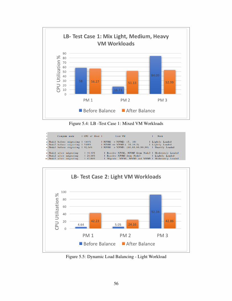
Figure 5.4: LB -Test Case 1: Mixed VM Workloads
Figure 5.5: Dynamic Load Balancing - Light Workload
56
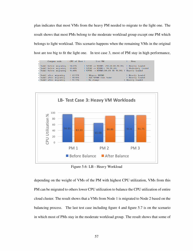
plan indicates that most VMs from the heavy PM needed to migrate to the light one. The
result shows that most PMs belong to the moderate workload group except one PM which
belongs to light workload. This scenario happens when the remaining VMs in the original
host are too big to fit the light one. In test case 3, most of PM stay in high performance,
Figure 5.6: LB - Heavy Workload
depending on the weight of VMs of the PM with highest CPU utilization, VMs from this
PM can be migrated to others lower CPU utilization to balance the CPU utilization of entire
cloud cluster. The result shows that a VMs from Node 1 is migrated to Node 2 based on the
balancing process. The last test case including figure 4 and figure 5.7 is on the scenario
in which most of PMs stay in the moderate workload group. The result shows that some of
57

Figure 5.7: Dynamic Load Balancing - Moderate Workload
VMs from the CPU with higher CPU utilization are migrated to the one with lower CPU
utilization to reduce the CPU utilization of the entire cloud cluster.
58

Chapter 6
LOAD CONSOLIDATION
Cloud data centers become more attractive because of they offen costs less than
traditional server due to virtualization technology. Although its performances are more
advanced than the previous, it still consumes a tremendous energy due to rapidly growing
user demand. Following [Sekhar, Jeba, and Durga, 2012], [Ferdaus, Murshed, Calheiros,
and Buyya, 2014], [Farahnakian, Ashraf, and Pahikkala, 2014], 55% of costs in a data
centers were to power 10-15% of all servers running at full capactiy. Moreover, due to pay-
as-you-go business model, the users shift the investment risk for under, or over-provisioning
to cloud provider where they handle the concern of fluctuating utilization. So, to increase
the annual revenue, the major concern of cloud provider is to design an energy-efficient
data center. From [Sekhar et al., 2012], this problem has been approached from various
perspectives: (1) Energy efficient hardware architecture, (2) virtualization of computing
resources, (3) energy-aware job scheduling, (4) dynamic voltage and frequency scaling,
(5) server consolidation, and (6) switching off unused nodes. In this project, we mainly
focused on server consolidation, creating an algorithm which packs all client requirements
into as minimal PMs as possible to reduce energy consumption without violating SLA
policies. By setting the static threshold calculated by CPU’s usages of all servers in cloud
cluster to 85% to guarantee the QoS. So, no PM is found over-utilized under consolidation
algorithm [Sami, Haggag, and Salem, 2015]. In the previous chapter, I mentioned system
59
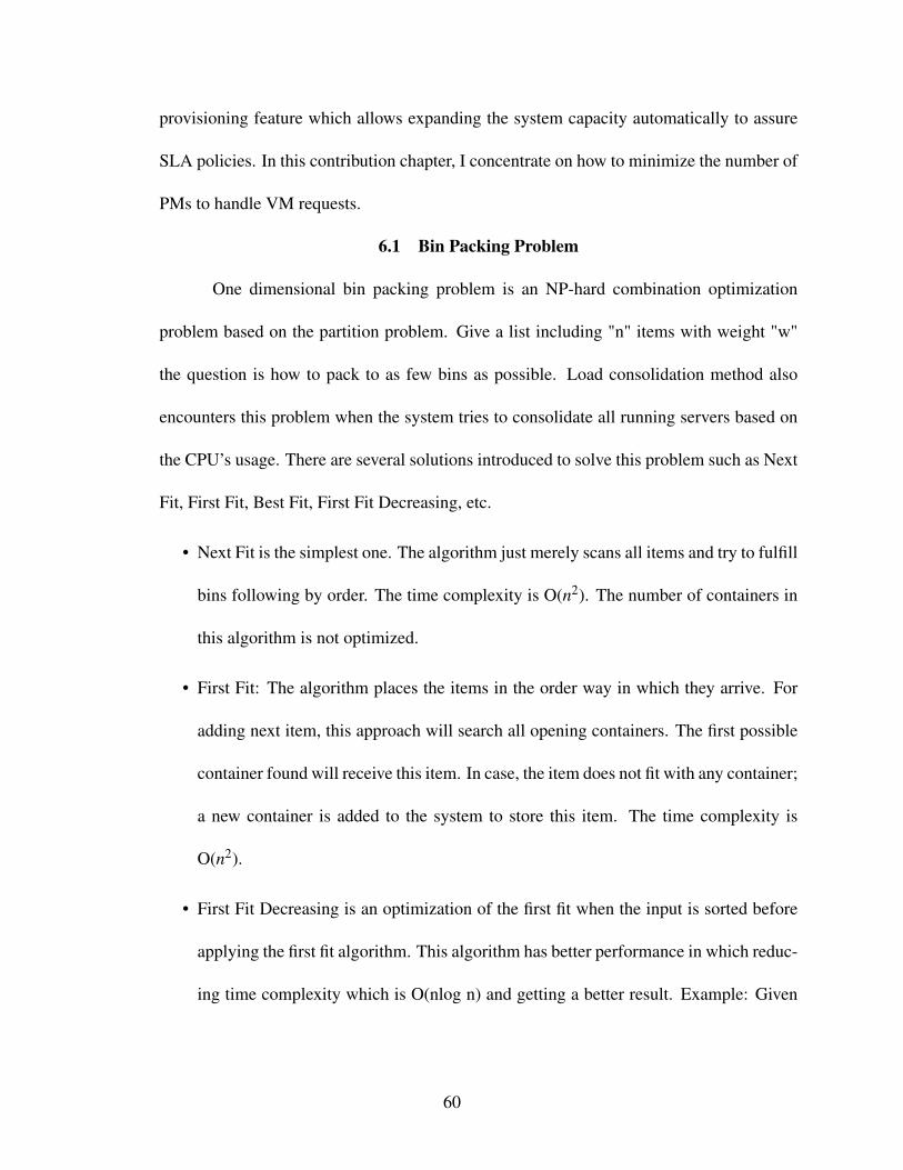
provisioning feature which allows expanding the system capacity automatically to assure
SLA policies. In this contribution chapter, I concentrate on how to minimize the number of
PMs to handle VM requests.
6.1 Bin Packing Problem
One dimensional bin packing problem is an NP-hard combination optimization
problem based on the partition problem. Give a list including "n" items with weight "w"
the question is how to pack to as few bins as possible. Load consolidation method also
encounters this problem when the system tries to consolidate all running servers based on
the CPU’s usage. There are several solutions introduced to solve this problem such as Next
Fit, First Fit, Best Fit, First Fit Decreasing, etc.
• Next Fit is the simplest one. The algorithm just merely scans all items and try to fulfill
bins following by order. The time complexity is O(n2). The number of containers in
this algorithm is not optimized.
• First Fit: The algorithm places the items in the order way in which they arrive. For
adding next item, this approach will search all opening containers. The first possible
container found will receive this item. In case, the item does not fit with any container;
a new container is added to the system to store this item. The time complexity is
O(n2).
• First Fit Decreasing is an optimization of the first fit when the input is sorted before
applying the first fit algorithm. This algorithm has better performance in which reduc-
ing time complexity which is O(nlog n) and getting a better result. Example: Given
60
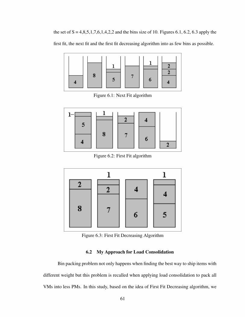
the set of S = 4,8,5,1,7,6,1,4,2,2 and the bins size of 10. Figures 6.1, 6.2, 6.3 apply the
first fit, the next fit and the first fit decreasing algorithm into as few bins as possible.
Figure 6.1: Next Fit algorithm
Figure 6.2: First Fit algorithm
Figure 6.3: First Fit Decreasing Algorithm
6.2 My Approach for Load Consolidation
Bin packing problem not only happens when finding the best way to ship items with
different weight but this problem is recalled when applying load consolidation to pack all
VMs into less PMs. In this study, based on the idea of First Fit Decreasing algorithm, we
61

designed a similar algorithm to consolidate the cloud servers based on the CPU’s usage.
Algorithm 5 is the pseudo code of our solution to consolidate the cloud servers.
6.3 Test Cases and Results
In this contribution chapter, we used the same technique when testing the load bal-
ancing algorithm’s performance. There is four test cases were applied in this study: (1)
Mixed, (2) Most of PMs are in the underutilized workload, (3) Most of PMs are in highly
performance, (4) Most of PM belong to moderately workload band. In the test case 1 and
Figure 6.4: LC - TB 1: Mix VM Workload
figure 6.5, we had a set of PM with random CPU utilization. The PM set we had which
consists of two heavy, two light and one moderate workload. The results showed that we
62

Figure 6.5: LC - Test Case 1: Mix VM Workload
could consolidate the system into three PMs and the remaining was turned off or switched
to lower power. In this test case 2 and figure 6.7, we assumed that almost PMs in the cloud
Figure 6.6: LC - TB 2: Light VM Workload
cluster were underutilized. The result showed that the PM which had the highest CPU uti-
lization took all VMs from other nodes. Other nodes after this processes were turned to
lower power or turned off. In test case 3 and figure 6.9, we tested our algorithm in a sit-
uation when most of PMs were handling the moderate workload. After implementing our
algorithm, we had three PMs were in high CPU utilization, one PM was in underutilizing,
and one PM was turned off. In the last test case 4 and figure 6.11, we tested the situation
63

Figure 6.7: LC - Test Case 2: Light VM Workload
Figure 6.8: LC - TB 3: Moderate VM Workload
when most PMs were in high performance. Consolidating on this matter was hard. How-
ever, our algorithm still impacted on PMs which had CPU utilization less than 85%. The
algorithm tried to rearrange the VM placements to get better consolidating CDCs. Figure
6.12 indicates the trade-off between CPU utilization and energy consumption. We used
Watts-up, a watt electricity usage monitor, to measure the energy consumed by the chang-
ing of CPU’s workload. According to the data collected from Watts-up, energy’s usage
curve tend to increase quickly when the CPU’s workload changes from idle to medium. In
contrast, energy’s usage grows slowly when CPU directs toward to high utilization. Fig-
64

Figure 6.9: LC - Test Case 3: Moderate VM Workload
Figure 6.10: LC - TB 4: Heavy VM Workload
ure 6.13 illustrates the total energy saving of a cloud cluster gained after apply our load
consolidation on four test cases.
65

Figure 6.11: LC - Test Case 4: Heavy VM Workload
Figure 6.12: The comparison between CPU utilization and Energy Consumption
66
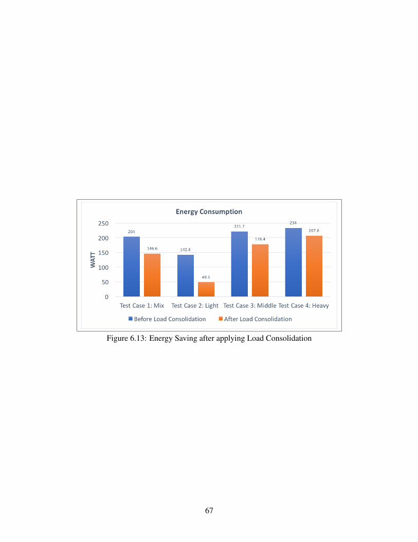
Figure 6.13: Energy Saving after applying Load Consolidation
67

Chapter 7
FUTURE WORK
In this study we mention two features used by cloud data centers which is load
balancing and load consolidation to reach the green cloud. In the load balancing chapter,
we provide an algorithm which uses a threshold like a standard to balance CPU’s utilization
of all compute nodes in a cloud cluster. This approach entirely depended on live VM
migration to implement. Live VM migration although is a useful technique to improve the
server’s performance but it’s also an expensive task and consumes the network bandwidth.
The new challenge for load balancing is to minimize the amount of live VM migration.
From [Farahnakian et al., 2014] Fahimed and et at. mentioned the downtime issue in live
VM migration. Because of the fluctuation of the operating system, there is no way to drop
downtime unless we don’t implement live VM migration. To overcome these drawbacks
they provide an approach which determines the extra workload in a VM then migrates to
another VM. Relating from their work, in the future work, we will focus on migrating the
extra workload of a VM to other VMs in the same host before moving the entire VM to
another host.
In the load consolidation chapter, we consolidated VM in the system based on the
CPU utilization percentage. However, when moving the VM from a server to another, there
are some issues needed to be pointed out such as space of RAM, the conflict between two
physical machines, etc. In the future work, we want to build a model which supports to
68

make a full consolidation plan. This model consists of functions which can compare the
different capacity between two or more servers. Furthermore, it’s necessary to predict the
future workload before making a consolidation plan.
69

Chapter 8
CONCLUSION
The overgrowing of cloud computing leads to growing cloud data centers, which
consume a considerable amount of energy. This study aims to design two features used by
cloud data centers which are not only to gain the utilization of server performance but also
strive to reduce the energy consumption. Two features mentioned are load balancing and
load consolidation. One is load balancing, a process of redistributing the entire workload
among compute nodes of the cloud cluster to make resource utilization and improve the
response time. In this study, we introduced a load balancing algorithm to handle three
issues. First is how to distribute VM requests from users to every compute node in the
cloud cluster. Second is how to optimize the CPU utilization of all compute nodes. The
last one is how to handle the extreme scenario. The second feature is load consolidation,a
process which migrates VMs on a certain amount of physical compute nodes as much
as possible and sets idle compute nodes in power saving state to save the energy. For
both features, besides describing the problems and giving the solution, we also support the
implementations with particular test cases. The results show that the energy consumption
of cloud data centers was reduced significantly without violating the performance of the
system.
70

REFERENCES
Accenture Microsoft Report (2010). Cloud Computing and Sustainability: The environ-mental Benefits of Moving to the cloud. Accenture Microsoft Report.
Agarwal, S. and A. Nath (2011). Green computing - new horizon of energy efficiencyand e-waste minimization U world perspective vis-à-vis indian scenario. EmergingTechnologies in E-Government.
Ahmad, R. W., A. Gani, S. H. A. hamid, S. A. Madani, F. Xia, and S. A. Madanii(2015). Virtual machine migration in cloud data centers: A review, taxonomy, andopen research issues. J Supercomput 71, 2473U2515.
Alzamil, I., K. Djemame, D. Armstrong, and R. Kavanagh (2015). Energy-aware pro-filing for cloud computing environments. Electronic Notes in Theoretical ComputerScience 318, 91 – 108.
Baba, S. S. G. and I. Bhusawal Jalgaon, Maharashtra (2015). A review on green comput-ing an eco friendly environment for different upcoming technologies. InternationalJournal of Trend in Research and Development 2(5).
Beloglazov, A., R. Buyya, Y. C. Lee, and A. Zomaya (2011). A taxonomy and surveyof energy-efficient data centers and cloud computing systems. Advance in comput-ers 82.
Botero, D. P., J. Szefer, and R. B. Lee (2013). Characterizing Hypervisor Vulnerabilitiesin Cloud Computing Servers.
Cherkasova, L. and R. Gardner (2005). Measuring cpu overhead for i/o processing inthe xen virtual machine monitor. USENIX Association.
Cisco (2008). Data center architecture overview. Technical report, Cisco.
Cuccureddu, G. (2011). GartnerŠs Hype Cycle 2011: Social Analytics And ActivityStreams Reach SThe PeakT. Business Insider.
Dabbagh, M., B. Hamdaoui, M. Guizani, and A. Rayes (2015). Toward energy-efficient cloud computing: Prediction, consolidation, and overcommitment. IEEENetwork 29(2), 56 – 61.
Emerson Network Power (2009). Energy Logic: Reducing Data Center Energy Con-
71
sumption by Creating Savings that Cascade Across Systems. 1050 Dearborn DriveP.O. Box 29186 Columbus, Ohio 43229: Emerson Network Power.
Erl, T., Z. Mahmood, and R. Puttini (2013). Cloud Computing: Concepts, Technologyand Architecture. Arcitura Education Inc.
Farahnakian, F., A. Ashraf, and T. Pahikkala (2014). Using ant colony system to con-solidate vms for green cloud computing. IEEE Transactions on Services Comput-ing 8(2), 187 – 198.
Feller, A., C. Morin, and E. Feller (2012). Energy-Aware Distributed Ant Colony BasedVirtual Machine Consolidation in IaaS Clouds Bibliographic Study.
Ferdaus, M. H., M. Murshed, R. N. Calheiros, and R. Buyya (2014). Virtual MachineConsolidation in Cloud Data Centers using ACO Metaheuristic.
G., A. S. and T. Edler (2015). On global electricity usage of communication technology:Trends to 2030. challenges 6, 117 – 157.
Garg, S. K. and R. Buyya (2011). Green Cloud computing and Environmental Sustain-ability.
Han, G., W. Que, G. Jia, and L. Shu (2016). An efficient virtual machine consolidationscheme for multimedia cloud computing. Sensors.
Hans, A. and S. Kalra (2015). A comprehensive study of various load balancing tech-niques used in cloud based biomedical services. International Journal of Grid Dis-tribution Computing 8(2), 127 – 132.
Kao, M. T., Y. H. Cheng, and S. J. Kao (2014). An automatic decision-making mecha-nism for virtual machine live migration in private clouds. mathematical problems inengineering.
Khan, A., A. Zugenmaier, D. Jurca, and W. Kellerer (2012). Network virtualization: Ahypervisor for the internet? IEEE Communications Magazine, 136 – 143.
Korri, T. (2009). Cloud comouting: utility computing over the internet. Seminar onInternetworking.
Liu, L., H. Wang, X. Liu, X. Jin, W. He, Q. Wang, and Y. Chen (2009). GreenCloud: ANew Architecture for Green Data Center.
Mesbahi, M. and A. M. Rahmani (2016, March). Load balancing in cloud computing:A state of the art survey. I.J Modern Education and Computer Science 3, 64–78.
72
Microsystem, S. (2009). Introduction to Cloud Computing Architecture. Sun Microsys-tem.
More, S. D. and A. Mohanpurkar (2015). Load balancing strategy based on cloud par-titioning concept. Multidisciplinary Journal of research in engineering and technol-ogy 5(7), 1107 – 1111.
Mukhedkar, P., H. D. Chirammal, and A. Vettathu (2016). Mastering KVM Virtualiza-tion. Packt.
Pires, F. L. and B. Baran (2015). A virtual machine place ment taxonomy. ResearchGate.
Qian, L., Z. Luo, Y. Du, and L. Guo (2009). Cloud computing: An overview. CloudCom,626 – 631.
Ramezani, F., J. Lu, and F. K. Hussain (2014). Task-based system load balancing incloud computing using particle swarm optimization. Int J Parallel Prog 42, 739–754.
Raza, K., V. K. Patle, and S. Arya (2012). A review on green computing foreco-friendlyand sustainable it. Journal of Computational Intelligence and Electronic Systems 1,1–14.
Readthedocs.io (2017). http://gluster.readthedocs.io/en/latest/.
Sahu, Y. and R. Pateriya (2013). Cloud computing overview with load balancing tech-niques. International Journal of Computer Applications 65(24), 40 – 44.
Sami, M., M. Haggag, and D. Salem (2015). Resource allocation and server consolida-tion algorithms for green computing. International Journal of Scientific & Engineer-ing Research 6(12), 313 – 316.
Saranya, D. and L. S. Maheswari (2015). Load balaning algorithms in cloud comput-ing: A review. International Journal of Advanced Research in Computer ScienceEngineering 5(7), 1107 – 1111.
Seetharaman, S. Energy Conservation in Multi-Tenant Networks through Power Virtual-ization.
Sekhar, J., G. Jeba, and S. Durga (2012). A survey on energy efficient server consolida-tion through vm live migration. International Journal of Advances in Engineering &Technology 5(1), 515 – 525.
Shanmugam, S. and N. C. S. N. Iyengar (2016). Effort of load balancer to achieve green
73

cloud computing: A review. International Journal of Multimedia and UbiquitousEngineering 11(3), 317–332.
Song, J., W. Liu, F. Yin, and C. Gao (2014). Tsmc: A novel approach for live virtualmachine migration. Journal of Applied Mathematics.
song, J., W. Liu, F. Yin, and C. Gao (2014). Tsmc: A novel approach for live virtualmachine migration. Research Article.
Telkikar, S., S. Talele, S. Vanarse, and A. Joshi (2014, August). Efficient load balancingusing vm migration by qemu-kvm. International Journal of Computer Science andTelecommunications 5(8), 49 – 53.
Thakur, S., A. Kalia, and J. Thakur (2014). A study on energy efficient server consolida-tion heuristics for virtualized cloud environment. International Journal of AdvancedResearch in Computer Engineering and Technology 3(4), 1175 – 1180.
Uddin, M., A. Shah, R. Alsaqour, and J. Memon (2014). Measuring efficiency of tierdata centers to implement green energy efficient data centers. Middle-East Journalof Scientific Research 15(2), 200–207.
Wang, L. and G. von Laszewski (2008). Scientific Cloud Computing: Early Definitionand Experience.
Xu, M., W. Tian, and R. Buyya (2017). A survey on load balancing algorithms for virtualmachines placement in cloud computing. Wiley, 1–16.
74

Appendices
75

Appendix AAPPENDIX A: SETTING UP THE ARCHITECTURE
A.1 Preparing Compute NodeThe following steps are used to setup the compute node. This assumes that virtual
extensions are enabled on the machine.1. Install Ubuntu 14.04 LTS2. Setup hardware.3. Install Python3 using sudo apt-get install Python34. Check the comparability of CPU using this command: egrep -c ’(vmx | svm) /proc/cpuinfo5. Install QEMU, libvirt and KVM following by: sudo apt-get install qemu-kvm libvirt-binubuntu-vm-builder bridge-utils6. Verify KVM installation by typing: kvm-ok7. Install Virsh manager: sudo apt-get install virt-manager 8. Install tool to connect to otherhypervisor: sudo apt-get install virt-manager ssh-askpass-gnome –no-install-recommends9. Using virt-manager to create VM, manage VM from other hypervisor.
A.2 Setting Up The Network FilesThe following steps are to build the network.
1. Vim into the /etc/network/interfaces file.2. Using your network configuration to change the network interface file to look like thefile shown below.3. Restart the network service by a command: sudo systemctl restart networking
Figure A.1: /etc/network/interfaces File
A.3 Building the Share-storage Network (using GlusterFS)To implement this tasks, you should have at least 2 computer.
1. Open file hosts from /etc/hosts by root privileges in the first2. Below the local host definition, you should add names and IP address of others servers
76

such as 192.168.11.11 Headnode, etc.3. Install Glusterfs by following these steps:i. apt-get updateii.sudo apt-get install python-software-propertiesiii. sudo apt-get install software-properties-commoniv. sudo add-apt-repository ppa:gluster/glusterfs-3.8v. sudo apt-get updatevi. sudo apt-get install glusterfs-servervii. Start and check glusterfs:service glusterd startservice glusterd statusviii. Configure firewall : iptables -I INPUT -p all -s <ip-address> -j ACCEPTix. Configure trust pool: from storagenode: gluster peer probe node1, gluster peer probenode2, gluster peer probe node3x. Check peer status: gluster peer statusxi. Create a brick in all server: mkdir -p /data/brick1/gv0xii. From single server: - this code depending on your storage architecture.gluster volume create gv0 replica 2 server1:/data/brick1/gv0 server2:/data/brick1/gv0gluster volume start gv0xiii. Mount volume to each compute node: mount -t glusterfs server1:/gv0 /mntxiv. Check result: ls -lA /data/brick1/gv0/xv. After creating network file system. All VM’s image should be stored in a brick whichall compute node can access. This is the requirement for live migration process.
77

Appendix BAPPENDIX B: LIVE VIRTUAL MACHINE MIGRATION
There are two way to execute live VM migration: 1. By code: virsh migrate –liveguest1-rhel6-64 qemu+ssh://host2.example.com/system 2. By virt-manager. Using migratefeature supported by virt-manager.
78

Appendix CAPPENDIX C: DYNAMIC LOAD BALANCING
C.1 Setting Up the Head Node1. To communicate between two machine to get the information, a socket is created
to pass data between 2 server. In my project, the Head-node will represent as client. Andeach compute node represent as a server. There are two codes running by Head-node andComputer-nodes to communicate each other.
C.2 Client
Figure C.1: client.py
C.3 ServerThere is a simple code from server side which will wait to receive the request from
client
Figure C.2: server.py
79

C.4 All functions need for load balancing and load consolidation2. All functions needed to run command line in python, get MAC address, get IP
address, etc.
Figure C.3: allFunc.py
C.5 Distributed Workload3. Code to implement distributed workload.
C.6 Optimize the CPU’s utilization4. When existing VM requests from user to cloud cluster, the head node will pro-
cess this request to distribute equally to every running PM. This code below represent thedistributed workload.
80

Figure C.4: distributeWorkload.py
81

Figure C.5: (continue) distributeWorkload.py
82

Figure C.6: CPUOtimization.py
83

Figure C.7: (continue) CPUOtimization.py
84

Appendix DAPPENDIX D: LOAD CONSOLIDATION
D.1 Load ConsolidationThe algorithm we applied in this study is First Fit Decreasing.
Figure D.1: loadConsolidation.py
85