green refrigeration
TRANSCRIPT


Index
▪ Method of Refrigeration
▪ Vapour Compression Cycle
▪ Refrigerants and their environmental issues
▪ Green Refrigerant
▪ Vapour Absorption Cycle– Ammonia Absorption
Refrigeration Cycle
– Einstein Refrigerator
▪ Gas Refrigeration Cycle
▪ Thermoelectric cooling
▪ Magnetic refrigeration
▪ Thermo-acoustic heat engine
▪ Solar Refrigeration
▪ Vortex Tube
▪ Stirling Cycle

What is Refrigeration?
▪ Refrigeration is a process in which work is done to move heat from one location toanother. The work of heat transport is traditionally driven by mechanical work, but canalso be driven by heat, magnetism, electricity, laser, or other means. Refrigeration hasmany applications, including, but not limited to: household refrigerators, industrialfreezers, cryogenics, and air conditioning. Heat pumps may use the heat output of therefrigeration process, and also may be designed to be reversible, but are otherwisesimilar to refrigeration units.
▪ Refrigeration has had a large impact on industry, lifestyle, agriculture and settlementpatterns. However, refrigeration technology has rapidly evolved in the last century,from ice harvesting to temperature-controlled rail cars. The introduction of refrigeratedrail cars contributed to the westward expansion of the United States, allowingsettlement in areas that were not on main transport channels such as rivers, harbours,or valley trails. Settlements were also popping up in infertile parts of the country, filledwith new natural resources. In most developed countries, cities are heavily dependentupon refrigeration in supermarkets, in order to obtain their food for daily consumption.The increase in food sources has led to a larger concentration of agricultural salescoming from a smaller percentage of existing farms. This has resulted in new foodsources available to entire populations, which has had a large impact on the nutrition ofsociety.

Method of Refrigeration
▪ Vapour Cycle– Vapour Compression Cycle
– Vapour Absorption Cycle
▪ Gas Cycle
▪ Thermoelectric Refrigeration
▪ Magnetic Refrigeration
▪ Solar Refrigeration
▪ Vortex Tube
▪ Thermo-acoustic Refrigeration
▪ Stirling Cycle

Vapour Compression Cycle
The vapour-compression cycle is used in most householdrefrigerators as well as in many large commercial andindustrial refrigeration systems.
In this cycle, a circulating refrigerant enters the compressoras vapour. From point 1 to point 2, the vapour is compressedat constant entropy and exits as a vapour at a higherpressure, but still below the vapour pressure at thattemperature. From point 2 to point 3, the vapour travelsthrough the condenser which cools the vapour until it startscondensing by removing additional heat at constantpressure. Between points 3 and 4, the liquid refrigerant goesthrough the expansion valve where its pressure abruptlydecreases, causing flash evaporation and auto-refrigerationof the liquid. That results in a mixture of liquid and vapour at alower temperature at point 4. The cold liquid-vapour mixturethen travels through the evaporator tubes and is completelyvaporized by cooling the warm air (from the space beingrefrigerated). The resulting refrigerant vapour returns to thecompressor inlet at point 1 to complete the thermodynamiccycle.
Fig. 1
What is Refrigerant?
▪ Refrigerants are substances that can be used in the refrigeration cycle of airconditioning and refrigeration equipment because of their thermodynamicproperties. In most cycles it undergoes phase transitions from a liquid to agas and back again. Fluorocarbons, especially chlorofluorocarbons, becamecommonplace in the 20th century. Other refrigerants used in variousapplications are ammonia, sulphur dioxide, and non-halogenatedhydrocarbons such as propane.
▪ The ideal refrigerant would have favourable thermodynamic properties, benoncorrosive to mechanical components, and be safe, including free fromtoxicity and flammability. The desired thermodynamic properties are aboiling point somewhat below the target temperature, a high heat ofvaporization, a moderate density in liquid form, a relatively high density ingaseous form, and a high critical temperature.

Refrigerant environmental issues
The inert nature of many halogens, chlorofluorocarbons (CFC) and hydrochlorofluorocarbons (HCFC), with the benefits of their being non-flammable and nontoxic, made them good choices as refrigerants, but their stability in the atmosphere and their corresponding global warming potential and ozone depletion potential raised concerns about their usage.
CFCs and HCFCs are being phased out under the Montreal Protocol, an international agreement to protect the ozone layer. They have been controlled by the Montreal Protocol since 1987 because of their ozone depleting potential and high global warming potentials.
Fig. 2


Different groups of refrigerants and their ozone depletion and global warming potentials
Substance group Abbreviation Ozone Depletion Potential
Global Warming Potentials
Example(refrigerant/foam blowing
agent)
Saturatedchlorofluorocarbons
CFC 0.6-1 4750-14,440 R11, R12
Saturatedhydrochlorofluorocarbons
HCFC 0.02-0.11 77-2,310 R22, R141b
Saturatedhydrofluorocarbons
HFC - 124-14,800 R32, R134a
Unsaturatedhydrochlorofluorcarbons
u-HCFC <0.001 0-10 R1233zd
Unsaturatedhydrofluorocarbons
u-HFC - <1-12 R1234yf
Natural refrigerants - - 0-3 R744 (carbon dioxide)R717(ammonia)R290 (propane)

Green Refrigerant
Consumption of HFCs however is growing dramatically world-wide due to their function asreplacement substances for CFCs and HCFCs. Nevertheless HFCs are greenhouse gases. Their useshould be avoided in order to slow global warming. Unsaturated HFCs (u-HFCs, also marketed ashydrofluoroolefins, or “HFOs”) are synthetically made HFCs with no ODP and low GWP that havebeen developed specifically to fulfil regulations that prohibit HFCs with higher GWP (e.g., above 150).Some are slightly flammable and combustion can form hydrogen fluoride. In the atmosphere theirdecomposition leads to the formation of trifluoroacetic acid (TFA), which is a strong acid with toxicityto some organisms. There is no known degradation mechanism for TFA.
Natural refrigerants are climate friendly. They have a very low or zero global warming potential andzero ozone depletion potential. Natural refrigerants are the naturally occurring substances CO2,ammonia, water, air and hydrocarbons such as propane, isobutene and propene/propylene. Theirproduction is not energy intensive as even the hydrocarbons can be obtained without chemicaltransformation by separation. Natural refrigerants are widely used in some RAC applications. Naturalrefrigerants can often be sourced as by-products from other processes. Recycling or disposal after usein cooling systems is easier than with CFCs, HCFCs and HFCs. All natural refrigerants havecharacteristics that require additional safety measures, compared to conventional CFCs, HCFCs andHFCs. Hydrocarbons (HCs) are flammable and ammonia is flammable, corrosive and of highertoxicity. Simple measures such as the use of appropriate materials, the selection of safe componentsand technician training can offset these undesirable characteristics

Vapour Absorption Cycle
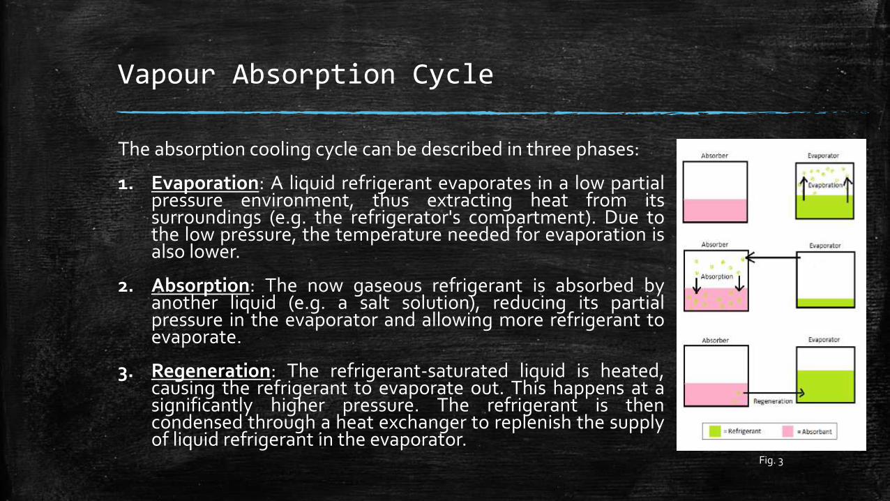
The absorption cooling cycle can be described in three phases:
1. Evaporation: A liquid refrigerant evaporates in a low partialpressure environment, thus extracting heat from itssurroundings (e.g. the refrigerator's compartment). Due tothe low pressure, the temperature needed for evaporation isalso lower.
2. Absorption: The now gaseous refrigerant is absorbed byanother liquid (e.g. a salt solution), reducing its partialpressure in the evaporator and allowing more refrigerant toevaporate.
3. Regeneration: The refrigerant-saturated liquid is heated,causing the refrigerant to evaporate out. This happens at asignificantly higher pressure. The refrigerant is thencondensed through a heat exchanger to replenish the supplyof liquid refrigerant in the evaporator.
Fig. 3

Ammonia Absorption Refrigeration Cycle- an Example of Vapour Absorption Cycle
▪ Ammonia vapour is vigorously absorbed in water. So whenlow-pressure ammonia vapour from the evaporator comes incontact in the absorber with weak solution coming fromgenerator is readily absorbed, by releasing latent heat ofcondensation. The temperature of the solution rises, whileabsorber gets cooled.
▪ Now the absorber is pumped to generator through heat-exchanger. In generator some heat is being added and henceby rectifying fresh gas is sent to condenser and solution toabsorber through heat-exchanger.
▪ Now fresh gas is condensed into condenser. And thecondensed liquid is sent to evaporator through heat-exchanger & expansion valve.
▪ In evaporator liquid evaporates by taking latent heat ofevaporation from the sink. And the evaporated liquid is sentto absorber through heat-exchanger.
Fig. 4

Einstein refrigerator
▪ The Einstein–Szilard or Einstein refrigerator is an absorption refrigerator whichhas no moving parts, operates at constant pressure, and requires only a heatsource to operate. It was jointly invented in 1926 by Albert Einstein and hisformer student Leó Szilárd.
▪ The machine is a single pressure absorption refrigerator, similar in design to agas absorption refrigerator. The refrigeration cycle uses ammonia pressureequalizing fluid, butane refrigerant, and water absorbing fluid, has no movingparts, and does not require electricity to operate, needing only a heat source,e.g. a small gas burner or electric heating element or even solar energy.
▪ On the cold side of a conventional refrigerator, a refrigerant evaporates at atemperature dependent pressure, 𝑃𝑟𝑒𝑓(𝑇𝑙𝑜𝑤). Evaporation absorbs heat fromwhatever is being cooled, and the vapor flows to a compressor. In an equivalentEinstein refrigerator, the refrigerant liquid evaporates at what is now a partialpressure 𝑃𝑟𝑒𝑓(𝑇𝑙𝑜𝑤) mixing with a flow of ammonia vapor to form a gas with atotal pressure near the system pressure: 𝑃𝑟𝑒𝑓+ 𝑃𝑎𝑚𝑛 = 𝑃𝑠𝑦𝑠. The mixture flows,not to a pump, but to an ammonia absorber.

Einstein refrigerator
▪ On the hot side of a conventional refrigerator, a compressor raises the pressureof the refrigerant vapor, enabling it to condense at a relatively high temperatureto deliver heat to an external heat exchanger. On the hot side of a Einsteinrefrigerator, an ammonia absorber raises the partial pressure of the refrigerantvapor to accomplish the same result. The absorber works by removing ammoniavapor by dissolving it in water.
▪ The absorber works by removing ammonia vapor by dissolving it in water. Asthis happens, the gas mixture flows to maintain the nearly constant pressure𝑃𝑠𝑦𝑠, and as a consequence, the partial pressure of the refrigerant, 𝑃𝑟𝑒𝑓, canapproach 𝑃𝑠𝑦𝑠. At this higher partial pressure, it can condense and deliver heat toan external heat convector, as in a conventional refrigerator.
▪ The condensed refrigerant liquid cannot dissolve in water and, in the case ofbutane, it will float, making it easy to separate and return to the evaporator.Meanwhile, the ammonia/water solution flows to an ammonia generator, wherethe heat source that powers the refrigerator raises the temperature of thesolution, driving out the ammonia and providing the ammonia vapor that is theother input to the evaporator. This is the operating principle of the system.
Fig. 5

Gas Cycle
▪ When the working fluid is a gas that is compressed andexpanded but doesn't change phase, the refrigerationcycle is called a gas cycle. Air is most often this workingfluid. As there is no condensation and evaporationintended in a gas cycle, components corresponding tothe condenser and evaporator in a vapour compressioncycle are the hot and cold gas-to-gas heat exchangersin gas cycles.
▪ The gas cycle is less efficient than the vapourcompression cycle because the gas cycle works on thereverse Brayton cycle instead of the reverse Rankinecycle. As such the working fluid does not receive andreject heat at constant temperature. In the gas cycle,the refrigeration effect is equal to the product of thespecific heat of the gas and the rise in temperature ofthe gas in the low temperature side. Therefore, for thesame cooling load, a gas refrigeration cycle needs alarge mass flow rate and is bulky.
Fig. 6

Thermoelectric cooling
Thermoelectric coolers operate by the Peltier effect (which also goes bythe more general name thermoelectric effect). The device has twosides, and when DC current flows through the device, it brings heatfrom one side to the other, so that one side gets cooler while the othergets hotter. The "hot" side is attached to a heat sink so that it remains atambient temperature, while the cool side goes below roomtemperature. In some applications, multiple coolers can be cascadedtogether for lower temperature.
Two unique semiconductors, one n-type and one p-type, are usedbecause they need to have different electron densities. Thesemiconductors are placed thermally in parallel to each other andelectrically in series and then joined with a thermally conducting plateon each side. When a voltage is applied to the free ends of the twosemiconductors there is a flow of DC current across the junction of thesemiconductors causing a temperature difference. The side with thecooling plate absorbs heat which is then moved to the other side of thedevice where the heat sink is. TECs are typically connected side by sideand sandwiched between two ceramic plates. The cooling ability of thetotal unit is then proportional to the number of TECs in it
Fig. 7
Fig. 8

Magnetic refrigeration
Magnetic refrigeration is a cooling technology based on the magneto caloric effect.Compared to traditional gas-compression refrigeration, magnetic refrigeration issafer and more environmentally friendly because it does not use harmful, ozone-depleting coolant gases, quieter, more compact, and has a higher cooling efficiency.The magneto caloric effect is a magneto-thermodynamic phenomenon in which atemperature change of suitable material is caused by exposing the material to achanging magnetic field.
In that part of the refrigeration process, a decrease in the strength of an externallyapplied magnetic field allows the magnetic domains of a magneto caloric materialto become disoriented from the magnetic field by the agitating action of thethermal energy (phonons) present in the material. If the material is isolated so thatno energy is allowed to (re)migrate into the material during this time, (i.e., anadiabatic process) the temperature drops as the domains absorb the thermalenergy to perform their reorientation.
First, a strong magnetic field is applied to the refrigerant, forcing its variousmagnetic dipoles to align and putting these degrees of freedom of the refrigerantinto a state of lowered entropy. The heat sink then absorbs the heat released by therefrigerant due to its loss of entropy. Thermal contact with the heat sink is thenbroken so that the system is insulated, and the magnetic field is switched off,increasing the heat capacity of the refrigerant, thus decreasing its temperaturebelow the temperature of the heat sink.
Fig. 9

Thermo-acoustic heat engine
▪ Thermo acoustic engines (sometimes called "TA engines") are thermoacoustic devices which use high-amplitude sound waves to pump heat from oneplace to another. Compared to vapor refrigerators, thermoacoustic refrigeratorshave no ozone-depleting or toxic coolant and few or no moving parts thereforerequire no dynamic sealing or lubrication.
▪ A thermoacoustic device basically consists of heat exchangers, a resonator, anda stack (on standing wave devices) orregenerator (on travelling wave devices).Depending on the type of engine a driver or loudspeaker might be used as wellto generate sound waves.
▪ Acoustic waves experience displacement oscillations, and temperatureoscillation in association with pressure variations.in order to produce thermoacoustic effect, these oscillation in the gas should occur close to a solid surface,so that heat is transferred to and from the surface. A stack of closely placedparallel plates is placed in the thermo acoustic device in order to provide such asolid surface. The thermo acoustic phenomenon occurs by the interaction of thegas particles and the stack plate. When large temperature gradients are createdacross the stack, sound waves are generated. In the reverse case, the acousticwork in order to create temperature gradient across the stack, which is used totransfer heat from a low temperature medium to a high temperature medium.
Fig. 10

Solar Refrigeration
▪ Refrigerator that runs on electricityprovided by solar energy are called solarrefrigeration. These type of solarrefrigeration can minimize the harmfulimpact on environment as well as thecost of fuel.
▪ There are three types of solarrefrigeration systems: photovoltaicoperated refrigeration cycle, solarmechanical refrigeration and absorptionrefrigeration.
▪ Solar refrigerators are environmentalfriendly and beneficial in terms oflongevity and scalability.
▪ Their disadvantages are that their COP islow, bulky arrangement and high initialinvestment.

Vortex Tube
▪ The vortex tube is a mechanical device that separates a compressed gas into hotand cold streams. The air emerging from the "hot" end can reach temperatures of200 °C, and the air emerging from the "cold end" can reach -50 °C. It has no movingparts. Pressurized gas is injected tangentially into a swirl chamber and acceleratedto a high rate of rotation. Due to the conical nozzle at the end of the tube, only theouter shell of the compressed gas is allowed to escape at that end. The remainder ofthe gas is forced to return in an inner vortex of reduced diameter within the outervortex.
▪ The main physical phenomenon of the vortex tube is the temperature separationbetween the cold vortex core and the warm vortex periphery. Under thisfundamental approach, this is explained with the work equation of Euler, alsoknown as Euler's turbine equation, which can be written in its most general vectorform as:
▪ 𝑇 −𝑣⋅⍵ × 𝑟
𝐶𝑝= constant
▪ where T is the total, or stagnation temperature of the rotating gas at radial position 𝑟, the absolute gas velocity as observed from the stationary frame of reference isdenoted with 𝑣; the angular velocity of the system is ⍵ and 𝐶𝑝 is the isobaric heatcapacity of the gas. The above equation is valid for an adiabatic turbine passage; itclearly shows that while gas moving towards the centre is becoming colder theperipheral gas in the passage is becoming faster. Therefore, vortex cooling is due toangular propulsion. The more the gas cools by reaching the centre, the morerotational energy it delivers to the vortex and it rotates even faster
Fig. 15

Stirling cycle
▪ The Stirling cycle is a thermodynamic cycle that was invented, developed and patented in 1816 by Reverend Dr. Robert Stirling with help from his brother, an engineer. The Stirling cycle is an altered version of the Carnot cycle in which the two isentropic processes featured in the Carnot cycle are replaced by two constant-volume regeneration processes. The cycle is the same as most other heat cycles in that there are four main processes: Isothermal expansion. The expansion space is heated externally, and the gas undergoes near-isothermal expansion.
1. Isothermal expansion: The expansion space is heated externally, and the gas undergoes near-isothermal expansion
2. Constant-volume heat removal: The gas is passed through the regenerator, thus cooling the gas, and transferring heat to the regenerator for use in the next cycle.
3. Isothermal compression: The compression space is intercooled, so the gas undergoes near-isothermal compression.
4. Constant-volume heat addition: The compressed air flows back through the regenerator and picks up heat on the way to the heated expansion space.
Fig. 16
Fig. 17

References and Links
▪ Notes: Engineering Thermodynamics by P.K. Nag
Engineering Thermodynamics by Cengel and Boles
External Links: http://en.wikipedia.org/wiki/Einstein_refrigerator
http://www.slideshare.net/devakumar21/solar-
refrigeration-36746340
http://en.wikipedia.org/wiki/Magnetic_refrigeration
http://en.wikipedia.org/wiki/Thermoacoustic_heat_engine

Acknowledgement
This project consumed dedication, hard work and sincerity. Still implementation wouldn’t have been possible if we didn’t have the support of many individuals. We want to take this opportunity to extend our sincere thanks to Prof. Amitabha Dutta, Prof. Ashok Kumar Santra and Mr. Mithun Das who devoted their time and
knowledge for the implementation of our lab works.
