greene county resource management department
TRANSCRIPT

1
APPENDIX T – POLE BARN
POLE BARNS ACCESSORY BUILDINGS &
LIVING AREAS IN POLE BARNS/ACCESSORY BUILDINGS
BASIC CODE INFORMATION
GREENE COUNTY RESOURCE MANAGEMENT DEPARTMENT
Building Regulations Division
940 North Boonville, Room 305 Springfield, Missouri
Telephone 417 - 868-4015 Fax 417 - 868-4175

2
INTRODUCTION
THIS INFORMATION IS BASED ON THE 2012 INTERNATIONAL 0NE-
AND TWO-FAMILY DWELLING CODE AND OTHER ADOPTED
GREENE COUNTY AMENDMENTS.
THIS HANDOUT IS ONLY PROVIDED AS A CONVENIENT SOURCE
FOR BASIC INFORMATION AND DOES NOT ADDRESS ALL THE
CODES NOR DOES THIS INFORMATION TAKE THE PLACE OF ANY
ADOPTED CODE OR AMENDMENTS.
THIS INFORMATION SIMPLY ACTS AS AN INSTRUMENT TO BETTER
PRESENT AND CLARIFY SOME OF THE CODE INTERPRETATIONS
AND ENFORCEMENT AND DOES NOT REPRESENT THE
REQUIREMENTS FOR ANY BUILDING THAT FALLS UNDER THESE
OCCUPANCIES; ASSEMBLY, EDUCATION, FACTORY & INDUSTRIAL,
HIGH HAZARD, INSTITUTIONAL, MERCANTILE, RESIDENTIAL
(other than one and two family), AND THESE USE GROUPS;
STORAGE, UTILITY AND MISCELLANEOUS OCCUPANCIES, WHERE
THE BUILDINGS ARE NOT AN ACCESSORY TO ONE-AND TWO-
FAMILY DWELLINGS AND WOULD NOT BE CLASSIFIED AS AN
AGRICULTURE STRUCTURE.
3
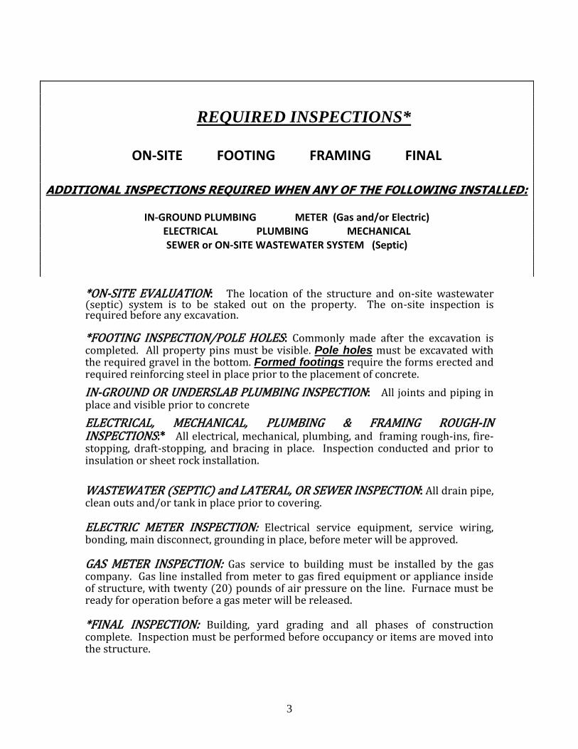
*ON-SITE EVALUATION: The location of the structure and on-site wastewater (septic) system is to be staked out on the property. The on-site inspection is required before any excavation. *FOOTING INSPECTION/POLE HOLES: Commonly made after the excavation is completed. All property pins must be visible. Pole holes must be excavated with the required gravel in the bottom. Formed footings require the forms erected and required reinforcing steel in place prior to the placement of concrete.
IN-GROUND OR UNDERSLAB PLUMBING INSPECTION: All joints and piping in place and visible prior to concrete
ELECTRICAL, MECHANICAL, PLUMBING & FRAMING ROUGH-IN INSPECTIONS:* All electrical, mechanical, plumbing, and framing rough-ins, fire-stopping, draft-stopping, and bracing in place. Inspection conducted and prior to insulation or sheet rock installation.
WASTEWATER (SEPTIC) and LATERAL, OR SEWER INSPECTION: All drain pipe, clean outs and/or tank in place prior to covering. ELECTRIC METER INSPECTION: Electrical service equipment, service wiring, bonding, main disconnect, grounding in place, before meter will be approved. GAS METER INSPECTION: Gas service to building must be installed by the gas company. Gas line installed from meter to gas fired equipment or appliance inside of structure, with twenty (20) pounds of air pressure on the line. Furnace must be ready for operation before a gas meter will be released. *FINAL INSPECTION: Building, yard grading and all phases of construction complete. Inspection must be performed before occupancy or items are moved into the structure.
REQUIRED INSPECTIONS*
ON-SITE FOOTING FRAMING FINAL
ADDITIONAL INSPECTIONS REQUIRED WHEN ANY OF THE FOLLOWING INSTALLED:
IN-GROUND PLUMBING METER (Gas and/or Electric)
ELECTRICAL PLUMBING MECHANICAL SEWER or ON-SITE WASTEWATER SYSTEM (Septic)

4
INSPECTIONS It is the responsibility of the person and/or agent listed as the owner on the permit to obtain the proper inspections. The failure to obtain the proper inspections will result in the uncovering of work. EXAMPLE: Placing poles or concrete in footing holes or forms before being approved by the building inspector. THE PERMIT NUMBER OR ADDRESS IS REQUIRED TO BE POSTED and VISIBLE FROM THE STREET AT ALL TIMES DURING THE CONSTRUCTION. INSPECTIONS WILL NOT BE CONDUCTED IF THIS INFORMATION IS NOT POSTED. A PERMANENT ADDRESS MUST BE POSTED BEFORE A FINAL INSPECTION IS CONDUCTED.
OFFICE HOURS: 8:00 AM – 4:30 PM MONDAY THRU FRIDAY
ALL LEGAL STATE HOLIDAYS OBSERVED
REQUEST FOR INSPECTIONS: All inspections must be called in to
the Greene County Building Regulation Department at least ONE DAY prior to
the requested inspection/inspections. The requested inspection/inspections
must be ready by 8:30 AM on the requested day of the inspection/inspections.
This scheduling includes all inspections. Inspections will be conducted
according to the inspector’s route and schedule.
If the requested inspection(s) are not going to be ready on the day requested,
please call to cancel and reschedule. All rescheduling has to be done by calling
the office.
TO SCHEDULE AN INSPECTION: Call 417 - 868-4015. We will require the following information: Permit number, address, individuals name requesting the inspection and a contact telephone number.

5
BUILDING INFORMATION
DESIGN LOADS: Roof Live load – 20 PSF
Ground Snow load – 20 PSF
Wind Speed – 90 MPH
Seismic Design Category – B
Soil Minimum Bearing Capacity – 2,500 PSF
ENGINEERING REQUIREMENTS: A Missouri licensed design professional is
required to design for the following;
Other loads such as loft areas, hoist or other attached loads require a design for
the footings/piers and structure.
Any building pad that has fill material placed on it shall have a compaction test.
The fill material is required to be engineered from the bottom of the fill to the top of
the fill. The compaction tests are required to be submitted to Greene Building
Regulations before the footing or foundation holes are inspected.
Any wood pole barn structure that has a width exceeding forty (40) feet or
exceeds 5,000 square feet in area requires a designed set of plans. Plans
are to indicate the footings or piers, column attachments, structure and design
loads. Plans are to be submitted to Greene County Building Regulations with the
application for the building permit.
All wood trusses. Submit shop drawings and certification.
All metal or steel structures. Complete set of plans and shop drawings indicating
footings or piers, column attachments, structure and design loads. Plans are to be
submitted to Greene County Building Regulations with the application for the
building permit.
Pole foundation depths that are shallower than the required depth indicated in
the charts in this document for minimum hole depth.
POSTS: Wood posts are required to be a minimum six inch by six inch (6” X 6”) ACQ or
CCA treated.
EXITS: The distance from the egress door to the most remote area cannot exceed
seventy-five (75) feet. Over seventy five (75) feet will require two (2) or more egress doors
located remotely from each other.
ELECTRICAL REQUIREMENTS FOR POLE BARN / ACCESSORY
STRUCTURE: Installed according to the adopted National Electric Code.
HEATING-AIR CONDITIONING, PLUMBING and GAS SERVICE:
Installed according to the adopted International Codes.

6
POLE BARN STRUCTURES
FOOTING REQUIREMENTS
When the posts are placed in concrete the diameter of the hole is required to be 10
inches. The depth of the footing holes are according to the tables located on Page 7.
The bottom of the footing hole is required to have 4 inches of crushed stone placed
under the post. DO NOT PLACE CONCRETE UNDER THE POST.
When posts are placed in soil the diameter of the hole is required to be 12 inches.
The depth of the hole is according to the tables located on Page 7. The bottom of the
footing hole is required to have 4 inches of crushed stone under the post. The soil
placed around the pole is to be compacted.

7
POLES ARE REQUIRED TO BE A MINIMUM 6”X6” TREATED POST
POLES SPACED 8 FEET ON CENTER
DEPTH OF FOUNDATION HOLES
Maximum Clear
Truss Span
Soil Backfill Concrete Backfill
Eave Height
From Finish Grade
Eave Height
From Finish Grade
8 ft. 10 ft. 14 ft. 8 ft. 10 ft. 14 ft.
20 ft. 29” 37” 52” 28” 29” 40”
30 ft. 32” 40” 54” 28” 31” 41”
40 ft. 34” 42’ 55” 28” 32” 42”
POLES SPACED 10 FEET ON CENTER
DEPTH OF FOUNDATION HOLES
Maximum Clear
Truss Span
Soil Backfill Concrete Backfill Eave Height
From Finish Grade
Eave Height
From Finish Grade
8 ft. 10 ft. 14 ft. 8 ft. 10 ft. 14 ft.
20 ft. 34” 43” 60” 28” 33” 46”
30 ft. 37” 46” 62” 29” 35” 48”
40 ft. 40” 49” 64” 31” 37” 49”
Shallower pole depths must be engineered

8
TRUSS ATTACHMENT
When the truss design requires the placement of a truss between the posts, a ledger
or rim is required. The ledger is to a minimum of two (2) #2 grade, 2 X 10’s. One
placed on each side of the post as indicated in the examples. The ledgers are to be
attached to the posts and the center support with two (2) one-half inch carriage bolts
with washers and nuts. The trusses are required to be attached to the supports
with one (1) one-half inch carriage bolt.

9
TRUSS ATTACHED TO EVERY POST
Truss Notched Into Post: Notch is to be no deeper than 1 ½” into side of post.
The truss is to be attached to the post with one (1) one-half inch carriage bolt with
nut and washer. A number 2 grade 2 X 10 ledger or rim is required to be attached
from post to post with two (2) one-half inch carriage bolts and washers. LEDGER BOARD IS NOT ILLUSTRATED IN THE FOLLOWING EXAMPLE.
Truss Attached to Post: When the truss is attached on the side of every post
the truss is to be attached with one (1) one-half inch carriage bolt with washers and
nuts. A number 2 grade 2 X 10 ledger or rim is required to be attached from post to
post with two (2) one-half inch carriage bolts and washers. A minimum four (4) foot
long 2 X 4 is to be attached under the truss to the post with three (3) ½” by 5” lag
screws spaced a maximum of six (6) inches from each end and one (1) in the middle.

10
PURLINS
NAILERS
All walls shall be braced and sheathed.

11
CONVENTIONAL CONSTRUCTION
The following diagrams and tables represent the requirements for construction
using spread footings, rafters and ceiling joist combination. These tables are not
used with an engineered truss system and pole construction.
GIRDER and HEADER SPANS FOR EXTERIOR BEARING WALLS
Building Width in Feet
20
28
36
GIRDERS AND H HEADERS SUPPORTING THE FOLLOWIN
SIZE
SPAN
# JACK STUDS
SPAN
# JACK STUDS
SPAN
# JACK STUDS
Roof and ceiling
2 - 2 X 4
3-6
1
3-2
1
2-10
1
2 - 2 X 6
5-5
1
4-8
1
4-2
1
2 - 2 X8
6-10
1
5-11
2
5-4
2
2 - 2 x 10
8-5
2
7-3
2
6-6
2
2 - 2 x 12
9-9
2
8-5
2
7-6
2
3 - 2 x8
8-4
1
7-5
1
6-8
1
3 - 2 x 10
10-6
1
9-1
2
8-2
2
3 - 2 X 12
12-2
2
10-7
2
9-5
2
4 - 2 X 8
9-2
1
8-4
1
7=8
1
4 - 2 X 1
11-8
1
10-6
1
9-5
2
4 - 2 X 12
13-1
1
12-2
2
10-11
2

12

13

14
LIVING QUARTERS in BARNS/ ACCESSORY
BUILDINGS
Must comply with the adopted International One and Two Family Dwelling Code
and the following;
FOOTING REQUIREMENTS
Footings are required to extend to the exterior wall side of the supporting post on a
pole type structure. (SEE PAGE 16)
Bottom of footing is required to be a minimum of eighteen (18) inches below finish
grade.
The top of the footing or foundation shall extend above grade were as the finish
backfill or yard grade is a minimum of six (6) inches below the top of the finished
floor level.
Footings shall be a minimum of twelve (12) inches wide, eight (8) inches thick with
two (2) rows of #4 (½ inch) rebar in place before the concrete is poured. Rebar is to
be supported a minimum of four (4) inches from the bottom of the footing, lapped
and tied together.
WALLS and CEILINGS
All interior walls shall be fastened to the concrete with a mechanical fastener spaced
a maximum of six (6) feet on centers. (POWER NAILING IS NOT ACCEPTED)
All walls on the interior of the exterior walls around the living area and the wall
between the barn/accessory structure and living area are to be insulated and
covered with approved wall covering from the floor to the ceiling or roof.
The wall between the living area and the barn/accessory structure is required to be
covered with a minimum of 1/2” gypsum board applied to the barn or garage side.
The area over the living area is required to be insulated.
The ceiling of the living area is required to have a minimum of 1/2” gypsum board
applied to the bottom of the ceiling.

15
EGRESS
At least one (1) egress door must exit directly to the exterior of the living area. The
required door shall be a side-hinged door not less than thirty-six (36) inches in
width and six feet-eight inches (6’ 8”) in height.
All egress doors are required to be opened from the egress side without the use of a
key.
All areas used for sleeping rooms must have one (1) direct egress to the exterior of
the structure, ether a window or door.
Windows in a sleeping room shall be as follows;
1. The unit must be operable from the inside to a full clear opening without
the use of a key, tool, or special knowledge.
2. The sill height is not to be more than 44 inches above the floor.
3. The net clear opening requirement is to be obtained by normal operation of
the window form the inside.
4. Minimum net clear opening shall be 5.7 square feet or 821 square inches
for windows located more than 44 inches above the finished grade
adjacent to the window. Windows with the sill height 44 inches or less to
the finished grade adjacent to the window shall be a minimum net clear
opening of 5 square feet or 720 square inches.
5. Minimum window opening height is 24 inches and the minimum opening
width is 20 inches. EXAMPLE: A window with a height of 24 inches
would require a width greater than 20 inches to meet the required opening
and a window with a width of 20 inches would require a window with a
height greater than 24 inches to meet the required opening.
OPENINGS BETWEEN LIVING AREA AND BARN/ACCESSORY
STRUCTURE
No door or window can open into the sleeping area from the barn/accessory
structure.
A door from the barn/accessory structure opening into the living area (not allowed in sleeping area) must be a solid wood door a minimum of not less than 1 3/8 inch
in thickness, solid or honeycomb steel door no less than 1 3/8 inch thickness or a 20-
minute fire rated door. Panel doors do not have the required rating or thickness.
Windows are not allowed between the living area and barn/accessory structure.

16
SMOKE ALARMS
Required in all sleeping areas and outside of sleeping areas.
Smoke alarms are required to receive their primary power source from the building
wiring and have battery back up power.
Smoke alarms are to be interconnected so all alarms will activate when one alarm is
activated.
ELECTRIC: Must comply with adopted National Electric Code.
HEATING/AIR CONDITIONING, PLUMBING and GAS SERVICE: Must comply with the adopted International One and Two Family Building Code and
Amendments.
FOOTING FOR LIVING SPACE IN POLE STRUCUTURE
Y:\dave\2012 Code Adoption\FINAL DOCUMENTS effective 01-01-13\Appendix T -Pole Barn and Accessory Buildings REV
1.doc