greenhouse gas permit - epa archives · greenhouse gas permit application to construct a dri/hbp...
TRANSCRIPT


Greenhouse Gas Permit Application to Construct a DRI/HBP Plant at La Quinta
Prepared for voestalpine Corpus Christi, Texas
January 2013
www.erm.com


voestalpine
Greenhouse Gas Permit Application to Construct a DRI/HBP Plant at La Quinta
January 2013
Project No. 0172451 _________________________ John P. Hollar, P.E. (GA) Partner-in-Charge _________________________ Graham C. Donaldson, P.E. (NC) Project Manager ERM NC, Inc. 1130 Situs Court, Suite 250 Raleigh, North Carolina 27606 T: 919-233-4501 F: 919-233-4505


Environmental Resources Management i Texas Registered Engineering Firm F-2393
Table of Contents
1.0 INTRODUCTION AND BACKGROUND ............................................... 1
1.1 PROCESS OVERVIEW ................................................................. 1
1.1.1 General Process Description ............................................... 1
1.1.2 Iron Oxide Storage and Handling ....................................... 2
1.1.3 Reduction Reactor ............................................................... 3
1.1.4 Hot Discharge System......................................................... 3
1.1.5 Hot Briquetting System....................................................... 4
1.1.6 Product Material Handling .................................................. 4
1.1.7 Process Gas System ............................................................ 5
1.1.8 Reformer ............................................................................. 5
1.1.9 Heat Recovery System ........................................................ 6
1.1.10 Seal Gas and Purge Gas System ......................................... 6
1.1.11 Bottom Seal Gas System ..................................................... 6
1.1.12 Inert Gas System ................................................................. 7
1.1.13 Machinery and Process Cooling Water System .................. 7
2.0 EMISSIONS ANALYSIS ........................................................................... 8
3.0 REGULATORY REVIEW ......................................................................... 9
3.1 FEDERAL REGULATIONS.......................................................... 9
3.1.1 GHG Tailoring Rule ........................................................... 9
3.1.2 Mandatory Reporting Rule ................................................. 9
4.0 BEST AVAILABLE CONTROL TECHNOLOGY (BACT) ANALYSIS ................................................................................ 10
4.1 KEY STEPS IN A TOP-DOWN BACT ANALYSIS .................. 11
4.2 Greenhouse Gas Emissions ........................................................... 13
4.3 Description of GHG Control Technologies .................................. 13
4.3.1 CO2 Control Technologies ................................................ 13
4.3.2 Available Technologies for Reducing GHG Emissions in the Iron and Steel Industry .......................... 14
4.3.3 Emerging Technologies for Reducing GHG Emissions in the Iron and Steel Industry .......................... 16

Environmental Resources Management ii Texas Registered Engineering Firm F-2393
Table of Contents 4.3.4 Long-Term Opportunities for Reducing GHG
Emissions in the Iron and Steel Industry .......................... 18
4.3.5 CH4 Control Technologies ................................................ 24
4.3.6 N2O Control Technologies ................................................ 24
4.4 SUMMARY OF PROPOSED BACT ........................................... 24
4.5 REFORMER MAIN FLUE EJECTOR STACK .......................... 25
4.5.1 CO2e Emissions from the Reformer Main Flue Ejector Stack – Shaft Furnace ....................................................... 26
4.5.2 CO2e Emissions from the Reformer Main Flue Ejector Stack – Reformer .............................................................. 33
4.6 hot PRESSURE RELIEF VENT (flare) ....................................... 38
4.6.1 CO2e Emissions from the Hot Pressure Relief Vent (Flare)........................................................................................... 38
4.7 SEAL GAS VENT ........................................................................ 42
4.7.1 CO2e Emissions from the Seal Gas Vent .......................... 42
4.8 EMERGENCY GENERATOR AND FIRE PUMP ..................... 44
4.8.1 CO2e Emissions from the Emergency Generator and Fire Pump ................................................................................. 44
4.9 OTHER MEASURES ................................................................... 48
5.0 ADDITIONAL REQUIREMENTS UNDER PSD ................................... 50

Environmental Resources Management 1 Texas Registered Engineering Firm F-2393
1.0 INTRODUCTION AND BACKGROUND
voestalpine proposes to build a direct reduced iron (DRI) plant in Corpus Christi in San Patricio County in Texas. A site location map showing the location of the plant with respect to the surrounding vicinity is included in this document. For greenhouse gases (GHGs), a process overview is presented in the remainder of Section 1. Emission calculations used in this best available control technology (BACT) analysis are presented in Section 2. A regulatory review of potentially applicable federal, state, and local regulations related to GHG emissions is presented in Section 3. The details of the BACT analysis are presented in Section 4. Additional information is provided in appendices as follows:
• Appendix A – Emission Rate Calculations; • Appendix B – Figures. • Appendix C – Recently Issued Permits and Pending Applications; and
1.1 PROCESS OVERVIEW
1.1.1 General Process Description
The Direct Reduction Iron (DRI) process consists of two main components, a Reformer (to produce the reducing agent) and the DRI reactor (where the reaction occurs). The DRI process converts pre-processed iron oxide pellets into highly metallized iron in the form of direct reduced iron (DRI) or hot briquetted iron (HBI), which are ideal feed materials for high quality steelmaking. Reformer: The primary raw material source to produce the reducing gas for the reactor is natural gas. Natural gas is reacted with carbon dioxide and water vapor across a proprietary catalyst to produce a reducing gas rich in carbon monoxide and hydrogen. The important reforming reactions are: CH4 + CO2 2CO + 2H2 CH4 + H2O CO + 3H2 Both of these reforming reactions are endothermic and therefore require energy in the form of heat input. All heat input into the system will solely be from natural gas combusted on the heat side of the reformer. Reduction: Most naturally occurring iron oxide has the chemical composition of hematite, Fe2O3, and contains about 30 percent oxygen by weight. In the DRI - process, the chemically bonded oxygen in the iron ore is removed at elevated temperatures by

Environmental Resources Management 2 Texas Registered Engineering Firm F-2393
reaction with carbon monoxide (CO) and hydrogen (H2) contained in a reducing gas to produce metallic iron (Fe), while liberating carbon dioxide (CO2) and water vapor (H2O). The overall reduction reactions are: Fe2O3 + 3H2 2Fe + 3H2O Fe2O3 + 3CO 2Fe + 3CO2 An important property of the reducing gas is the reductant/oxidant ratio, or “gas quality.” The quality is a measure of the potential for the gas to reduce iron oxide. The quality is defined as the ratio of reductants to oxidants contained in the gas: Quality = reductant/oxidant ratio = moles (H2 + CO)/moles (H2O + CO2)
Experience has found that the optimum gas quality for hot, fresh reducing gas should be 10 or higher. Also, to obtain essentially complete reduction, the quality of the spent reducing gas exiting the process should be at least 2. Another important property of the reducing gas is the H2/CO ratio. Control of the H2/CO ratio affords thermally balanced reduction reactions since reduction with carbon monoxide is exothermic, and reduction with hydrogen is endothermic. That is, the heat required by the hydrogen reaction is balanced by the heat supplied by the carbon monoxide reaction. Therefore, proper reduction temperatures can be maintained without significant additional heat input from fuel combustion. The typical H2/CO ratio produced by the reformer is about 1.55:1. A description of the individual process areas is provided below and the Process Flow Diagrams for the facility are included in Appendix D.
1.1.2 Iron Oxide Storage and Handling Direct Reduction (DR) grade pellets are delivered in the surge bin at the port. After weighing the pellets, a conveyor transports the pellets to the pellet pile. The pellet pile is equipped with a stacker/reclaimer and will maintain a sufficient supply for one (1) month of operation. The pellets are weighed and transferred to the oxide day bins. The day bins act as a buffer of prepared oxide that is fed to the shaft furnace. The day bins then discharge to a screening operation to separate the off-specification fractions from the desired 6-20 mm oxide fractions. The desired oxide fractions are discharged on the oxide transfer conveyor. The off specification material is screened further to identify usable fractions. Unusable material is discarded.
The material on the oxide transfer conveyor is weighed and discharged onto the furnace feed conveyor. The furnace feed conveyor is a vertical, pocket type conveyor with flexible sidewalls that deliver material to the top of the shaft furnace structure. The closed furnace feed conveyor discharges through a riffler to the charge hopper at the top of the shaft furnace. The oxide coating station enables feeding of coating directly to the charge hopper of the shaft furnace. The

Environmental Resources Management 3 Texas Registered Engineering Firm F-2393
coating is a solid material consisting of cement, burnt lime, hydrated lime, and hydrated dolomite to assist in the reaction process. These materials are maintained in individual silos. A weight indicator in the charge hopper keeps the operator informed of the quantity of feed in the charge hopper. All process operations within the Iron Oxide Storage and Handling system are routed to various baghouses for the control of particulate emissions. The storage pile and associated operations are controlled with fugitive suppressants.
1.1.3 Reduction Reactor The reduction reactor is a patented furnace with a nominal 7.15-meter internal diameter refractory, lined with abrasion resistant and insulating brickwork/castables to minimize heat loss. Iron ore pellets enter the reactor through the upper dynamic seal leg and are uniformly distributed on the stockline by symmetrical feed pipes. A dynamic seal is created by a small flow of inert seal gas into the upper seal leg of the furnace. This small flow of inert seal gas into the furnace through the seal leg prevents the escape of furnace gases to the atmosphere, while still allowing the free flow of material by gravity into the furnace without the use of lockhoppers.
The iron ore pellets are reduced to metallic iron in the upper portion of the furnace (reduction zone) by contact with hot hydrogen and carbon monoxide gases that are generated in the reformer and flow counter current to the descending iron oxide. The temperature of the reducing gas is typically 840 – 1,000 °C, depending on the specific reactor operating conditions. Specially designed inlet ports (tuyeres) ensure that the reducing gases flow uniformly to the furnace burden. Spent reducing gas exits near the top of the reactor and enters the process gas system. The product material typically spends 3-4 hours in the reactor in order to achieve the desired product metallization and is then discharged from the furnace cone at temperatures above 700 °C. The discharge zone consists of the refractory lined furnace cone equipped with hydraulically operated burden feeders and a flow aid insert to aid the flow of the material within the cone. The reduction reactor is not directly vented to the atmosphere so it does not have a specific emission source associated with it. Seal gas (described below) is used to pressurize both the top and bottom of the reactor so that the system reducing gases do not vent to the atmosphere. Furthermore, the reactor does not produce a melted product; the product remains in solid form throughout the reaction process. However, during startup and shut down the system vents through the top gas scrubber to a flare; but, this is to deal with safety issues arising from high hydrogen concentrations associated with the startup and shutdown processes.
1.1.4 Hot Discharge System The hot reduced material is discharged from the furnace via a dynamic seal leg and a hydraulically driven variable speed hot wiper bar. The speed of the lower burden feeder is ratioed to the average discharge rate of the furnace to achieve a uniform flow of the material from the lower cone to the lower seal leg. The hot
Environmental Resources Management 4 Texas Registered Engineering Firm F-2393
material flows across the wiper bar and then passes through a set of hydraulically driven screens, which limit the maximum size of the product passing into the surge hopper of the product discharge chamber. The material is discharged from the surge hopper into one or more of several feed legs. These feed legs connect directly to either a briquette machine or the bypass feed screw. For safety, each leg is isolated from its respective discharge device by a slide gate and ball valve.
1.1.5 Hot Briquetting System The briquetting section includes briquette machines with individual grease lubrication stations, briquette strand separators, HBI cooling conveyors, and one bypass line. Hot DRI is supplied to each briquette machine by a screw feeder. The briquette machines are roll type machines which produce “pillow” shaped briquettes about 6 mm by 120 mm. Each roll contains dies which form the briquettes. One of the rolls is forced toward the other roll by means of a hydraulic pressure system, which ensures a uniform pressing force. The continuous briquette strand that exits the briquetting machine is fed to the strand separators to break the strands into individual briquettes, which are then fed to the HBI cooling system for slow cooling and discharge to the product handling system. Off-specification product (remet) produced during plant start-up or process upset bypasses the briquette machines and is discharged through a bypass feed leg to the bypass discharge feeder and then to the HBI cooling system. The HBI cooling conveyors will spray water to cool the HBI and will be equipped with vapor hoods to remove steam created by the process. Most of the mist will vaporize on contact with the hot HBI and the vapor will be exhausted to the atmosphere via vapor exhaust fans. The vapor removal system consists of ducts and fans designed to capture and minimize the release of steam into the briquette area. Outside air ducts will be directly connected to each vapor hood and vapor removal fans will supply the required amount of unheated outside air directly into the vapor hoods. Spray cooling water that does not vaporize will drain into collection pans and be routed to a sump and then to the waste water facility. The dust collection system is designed to minimize the escape of dust at the briquette machines. The system consists of an exhaust fan, a cyclone, an additional air valve, a dust collection scrubber, a sump, an exhaust stack, and associated ducts, hoods, pumps and valves. Dusty air and seal gas are collected and conveyed at a sufficient velocity to prevent settling and accumulation within the ducts. The gas stream then enters a venturi scrubber where water is sprayed onto the dust particles to create a slurry. The slurry is discharged from the scrubber and pumped to the basin upstream of the clarifier. Cleaned gases are pulled from the dust collection system by the exhaust fan and discharged into the atmosphere through a stack.
1.1.6 Product Material Handling The material is transferred from the briquette cooling conveyors to the HBI conveyors, which are equipped with product scales. The HBI product is transported to the product screening station 1 where it is separated into product fines (0-6.35mm) and HBI (6.35-120mm). The fines are fed into a ground floor

Environmental Resources Management 5 Texas Registered Engineering Firm F-2393
product fines bunker, while the HBI is weighed and transported on the product collection conveyor to the stacker conveyor for storage. The HBI product storage has a capacity of 100,000 tons per pile. The HBI is reclaimed from the HBI product storage and transported via conveyor to the product screening station 2, where it is screened; the HBI is weighed and transported via conveyor to the port. All process operations within the Product Material Handling system are routed to various baghouses for the control of particulate emissions. The storage pile and associated operations are controlled with fugitive suppressants.
1.1.7 Process Gas System Spent reducing gas (top gas) exits the reduction zone of the reactor through the refractory lined top gas duct and enters the top gas scrubber to be cleaned and cooled. Inside the top gas scrubber, the gas passes through two distinct processing zones. First the gas flows through the venturi portion of the scrubber where it is rapidly cooled and the particulate matter is wetted and removed. Then the warm gas is split into two streams that pass through two parallel packed beds (for additional cooling) and two sets of spin vanes (to remove water droplets) within the scrubber. After scrubbing and cooling, approximately two-thirds of the clean top gas (now called process gas) flows through a second set of mist eliminators and then to the inlet of the first stage process gas compressor, followed by a second compressor. These compressors are centrifugal type machines designated as first stage and second stage process gas compressors. After compression, the process gas is mixed with natural gas and preheated to form the feed gas for the reformer. The other one-third of the cleaned top gas (now called top gas fuel) is mixed with a small amount of natural gas and then passed through a mist eliminator to remove water droplets before fueling the reformer main burners. It is important to note that the Top Gas Scrubber is not a control device but a process device. The process gas system does not vent directly to the atmosphere during regular operation.
1.1.8 Reformer The reformer generates the hot reducing gas (H2 and CO) required to reduce the iron oxide in the shaft furnace. It has a proprietary tubular style design that reforms natural gas across a proprietary catalyst with both the water vapor and CO2 in the feed gas. Heat for the reforming reactions is supplied by floor fired (burners are on the floor) main burners, which are located on the bottom of the reformer box between tube rows and between the outside tube rows and the reformer wall. The air required for combustion is preheated in the heat recovery system before being directed to the burners with the main air blower. The reformer box is thermally insulated with refractory material. Natural gas-fired auxiliary burners maintain the reformer box temperature during plant idle

Environmental Resources Management 6 Texas Registered Engineering Firm F-2393
conditions to minimize both restart time and thermal cycling of the reformer tubes. Each reformer bay has a separate sized flue gas port to each of the flue gas headers to ensure uniform heat distribution along the reformer length. The flue gas headers are refractory lined and expansion joints are provided between the single sections of the headers to compensate for thermal expansion. The flue gas exiting the reformer box via the flue gas headers flows to the heat recovery system where the waste heat is recovered.
1.1.9 Heat recovery system The reformer flue gas exits on both sides of the reformer and enters the parallel train heat recovery system. Each parallel system contains combustion air pre-heaters and feed gas pre-heaters, all of which consist of alloy bundle type heat exchangers suspended in the refractory lined heat recovery ducts. The combustion air pre-heaters are designed to preheat the combustion air to about 600 °C in two stages. The feed gas pre-heaters located downstream of the combustion air pre-heater heat the feed gas to approximately 600 °C as well.
The flue gas exits the parallel trains through a common ejector stack which generates the required draft with a single ejector stack fan. The ejector stack is an induced draft (venturi type) flue gas stack. It uses the ejector stack fan to generate sufficient suction to pull the flue gases out of the reformer and through the heat recovery system. The heat recovery system increases the reformer capacity and reduces the net plant energy consumption by approximately 25-30 percent over the first generation designed in the 1960’s.
1.1.10 Seal gas and purge gas system Inert seal gas for the plant, which is used primarily for sealing the top and bottom of the furnace, is provided by the seal gas generation system. This system takes hot reformer flue gas and cools it in a seal gas cooler. The seal gas cooler is a packed bed, direct contact type cooler which cools the reformer flue gas to near ambient temperature. The cooled seal gas is then compressed by a positive displacement type compressor and then cooled in a shell and tube aftercooler to remove the heat of compression. The cooled seal gas passes through a mist eliminator and seal gas dryer. The seal gas dryer is a refrigerant type unit equipped with a stand-by compressor that removes moisture from the wet seal gas. This dry seal gas is then distributed to various plant users. Part of the dry seal gas is compressed by the purge gas compressors and dried in a desiccant dryer. The dry purge gas is stored in tanks to be used for emergency plant shutdown situations and for small high pressure requirements during normal operation.
1.1.11 Bottom seal gas system The furnace bottom seal gas system consists of a compressor, a dilution hood, a dust collection scrubber, a fan, and a stack to supply and exhaust seal gas for sealing the bottom of the shaft furnace. The bottom seal gas compressor, a

Environmental Resources Management 7 Texas Registered Engineering Firm F-2393
positive displacement run dry type, supplies dry seal gas to the lower seal leg of the shaft furnace at the required pressure. The bottom seal gas is vented through a vent line and collected in the dilution hood, which captures sufficient air to maintain a mixture of gases that remains below minimum explosive limits in the dust collection system. The mixture passes to the dust collection scrubber where entrained dust particles are removed and then the seal gas/air mixture is exhausted through the bottom seal dust collection fan and stack. In the event of an interruption in the seal gas supply, the inert gas generator or the purge gas system supply bottom seal gas while the problem is corrected.
1.1.12 Inert gas system An inert gas system supplies seal gas for the plant in the event that the reformer combustion system is not in operation. This system consists of an inert gas generator where natural gas and air are burned at close to the stoichiometric ratio, so that the product of combustion yields a suitable inert gas with a very low oxygen content. This system is not used under normal operations.
1.1.13 Machinery and process cooling water system The water system consists of a machinery cooling water circuit and a process cooling water circuit. Water system equipment is located outside the Core Plant Area. The machinery cooling water is a closed circuit that supplies cooling water to all indirect coolers such as burden feeders, rotating equipment lubrication oil, heat exchangers, etc. It consists of circulation pumps, a sump, plate and frame heat exchangers, and a scaling/corrosion inhibitor dosing system. Circulation pumps circulate hot water from the machinery cooling water sump through the heat exchanger on one side while cold process water is pumped through on the other side to cool the machinery cooling water. A head tank is used to supply cooling water to the water cooled furnace equipment. The process cooling water circuit supplies cooling water to the direct contact coolers and the process users, such as the top gas scrubber and the dust collection systems. It also provides the cooling water for the machinery cooling water heat exchangers. The process cooling water system consists of a sump, circulation pumps, process water cooling towers, and a clarifier system. Dirty, hot process water flows from the users to the clarifier. A dosing system injects a flocculating agent into the clarifier causing particulate matter to settle. Underflow from the clarifier is sent as a slurry to settling ponds for de-watering and overflow is sent to the process water sump. Clean, hot process water flows directly from the users to the process water sump, where it is mixed with the clarifier overflow. The water in the process water sump is cooled by passing through the process water cooling towers.

Environmental Resources Management 8 Texas Registered Engineering Firm F-2393
2.0 EMISSIONS ANALYSIS
This section summarizes the methodologies and emission factors used to calculate GHG emissions for each emission source type included in this project. As outlined in the USEPA document, PSD and Title V Permitting Guidance for Greenhouse Gases (USEPA, 2011), GHGs are a regulated NSR pollutant under the PSD major source permitting program. The six GHG pollutants are:
• Carbon dioxide (CO2); • Nitrous oxide (N2O); • Methane (CH4); • Hydrofluorocarbons (HFCs); • Perfluorocarbons (PFCs); and • Sulfur hexafluoride (SF6).
The voestalpine facility will not use or process HFCs, PFCs, or SF6 in the manufacturing process and does not believe these three compounds will be emitted as a result of the manufacturing process. Therefore, only emissions of CO2, CH4, and N2O were examined for comparison to the PSD thresholds. Emission calculations are included in Appendix A. For this BACT analysis, total GHG, on a carbon dioxide equivalent (CO2e) basis has been used. The amounts of CO2, CH4, and N2O were converted to tons of CO2e using the Global Warming Potential (GWP) factors from Subpart A of Part 98, Table A-1, as shown in the table below.
Table 2-1: Global Warming Potentials [100-Year Time Horizon] from Table A-1 to Subpart A of 40 CFR Part 98
Name CAS Number Chemical Formula Global Warming Potential (100 yr)
Carbon dioxide 124-38-9 CO2 1
Methane 74-82-8 CH4 21
Nitrous oxide 10024-97-2 N2O 310 TABLE 2-2: Summary of voestalpine Facility Emissions Compared to PSD Significant Emission Rates
Pollutant PSD Significant Emission Rate
(TPY)
Facility-Wide Emission Rate
(TPY)
Significant Source
Greenhouse Gases (GHG) as CO2e 100,000 1,814,144 Yes

Environmental Resources Management 9 Texas Registered Engineering Firm F-2393
3.0 REGULATORY REVIEW
The proposed project will be subject to federal and state regulatory requirements as outlined in the following sections. Only those regulations that are potentially applicable to the proposed project were reviewed in this application. The USEPA promulgated a Federal Implementation Plan (FIP) for Texas assuming the PSD permitting authority for large GHG-emitting sources in Texas in accordance with the thresholds established under the Tailoring Rule published on June 3, 2010. All other pollutants are regulated by the Texas Commission on Environmental Quality (TCEQ) under the State Implementation Plan (SIP) and are beyond the scope of this application.
3.1 FEDERAL REGULATIONS
3.1.1 GHG Tailoring Rule On June 3, 2010, the US Environmental Protection Agency (USEPA) issued a final rule addressing GHG emissions from stationary sources under the Clean Air Act (CAA) permitting programs. This final rule set thresholds for GHG emissions that defined when permits under the Prevention of Significant Deterioration (PSD)/New Source Review (NSR) and Title V Operating Permit programs are required for new and existing industrial facilities. The GHG PSD Tailoring rule defined a major new source of GHG emissions as emitting 100,000 short tons of CO2 equivalent (CO2e) and 100 tons per year (tpy)/250 tpy (depending on the source category) on a mass basis. A major modification under the rule was defined as an emission increase and net emissions increase of 75,000 tpy or more of GHGs on a CO2e basis and greater than zero tpy of GHGs on a mass basis. For the second phase of the Tailoring Rule, which began on July 1, 2011, PSD requirements for GHGs are triggered for new construction projects that have the potential to emit GHG emissions of at least 100,000 tpy. PSD requirements are triggered for modifications at existing sources only if the existing source’s GHG emissions are equal to or greater than 100,000 tpy on a CO2e basis and equal to or greater than 100 tpy/250 tpy on a mass basis, and the emission increase and net emission increase of GHGs from the modification would be equal to or greater than 75,000 tpy on a CO2 basis and greater than zero tpy on a mass basis. This application has been prepared because the CO2e emissions from the voestalpine facility (new construction) will exceed 100,000 tpy.
3.1.2 Mandatory Reporting Rule Under the Mandatory Reporting Rule (40 CFR Part 98), beginning in 2010, facilities with fuel burning equipment with actual CO2e emissions greater than or equal to 25,000 metric tpy must submit an annual GHG report that must cover all source categories and GHGs for which calculation methodologies are provided in subparts of the rule. The voestalpine facility will report GHG emissions under 40 CFR Part 98 as applicable.

Environmental Resources Management 10 Texas Registered Engineering Firm F-2393
4.0 BEST AVAILABLE CONTROL TECHNOLOGY (BACT) ANALYSIS
This application presents a full “top-down” BACT analysis. Under Title 30 of the Texas Administrative Code (TAC) Chapter 116, BACT shall be applied to reduce or eliminate air emissions from a new or modified facility. The TCEQ utilizes a tiered BACT analysis in implementing PSD and state BACT requirements. PSD BACT is applicable to all pollutants that are subject to PSD review. State-only BACT is applicable to all other pollutants which are emitted from a new or modified facility. Federal BACT is defined in 30 TAC 116.160 and 40 CFR 52.21(b)(12) as:
“An emissions limitation (including a visible emission standard) based on the maximum degree of reduction for each pollutant subject to regulation under Act which would be emitted from any proposed major stationary source or major modification which the Administrator, on a case-by-case basis, taking into account energy, environmental, and economic impacts and other costs, determines is achievable for such source or modification through application of production processes or available methods, systems, and techniques, including fuel cleaning or treatment or innovative fuel combustion techniques for control of such pollutant. In no event shall application of best available control technology result in emissions of any pollutant which would exceed the emissions allowed by any applicable standard under 40 CFR Parts 60 and 61. If the Administrator determines that technological or economic limitations on the application of measurement methodology to a particular emissions unit would make the imposition of an emissions standard infeasible, a design, equipment, work practice, operational standard, or combination thereof, may be prescribed instead to satisfy the requirement for the application of best available control technology. Such standard shall, to the degree possible, set forth the emissions reduction achievable by implementation of such design, equipment, work practice or operation, and shall provide for compliance by means which achieve equivalent results.”
State BACT is defined in 30 TAC 116.10(1) as:
“An air pollution control method for a new or modified facility that through experience and research, has proven to be operational, obtainable, and capable of reducing or eliminating emissions from the facility, and is considered technically practical and economically reasonable for the facility. The emissions reduction can be achieved through technology such as use of add-on control equipment or by enforceable changes in production processes, systems, methods or work practice.”
The USEPA guidance document, PSD and Title V Permitting Guidance for Greenhouse Gases (EPA 457/B-11-001), recommends the use of the five-step “top-down” BACT process established in the 1990 draft guidance New Source Review Workshop Manual to evaluate and select BACT for GHG. This process requires identification and consideration of available control technologies. The applicant

Environmental Resources Management 11 Texas Registered Engineering Firm F-2393
must then demonstrate control technologies that are infeasible due to engineering constraints. All remaining technologies are ranked in order of descending order of control effectiveness. The top-ranked control option must be selected unless the applicant can demonstrate that it is not viable due to adverse economic or environmental impacts. If the most effective technology is not selected, then the most effective alternative should be evaluated until an option is selected as BACT.
4.1 KEY STEPS IN A TOP-DOWN BACT ANALYSIS
The five basic steps of a “top-down” BACT analysis are listed below:
Step 1: Identify potential control technologies; Step 2: Eliminate technically infeasible options; Step 3: Rank remaining control technologies by control effectiveness; Step 4: Evaluate the most effective controls and document results; and Step 5: Select BACT.
These steps are discussed in more detail below.
Step 1 – Identify Potential Control Technologies
The first step is to identify potentially “available” control options for each emission unit and for each pollutant under review. Available options should consist of a comprehensive list of those technologies with a potentially practical application to the emissions unit in question. The list should include lowest achievable emission rate (LAER) technologies, innovative technologies, and controls applied to similar source categories.
For this analysis, the following types of information were researched:
• USEPA’s RACT/BACT/LAER Clearinghouse (RBLC) database; • Federal and state air quality permits; • Technical books and articles; and • Guidance documents.
Step 2 – Eliminate Technically Infeasible Options
The second step is to eliminate technically infeasible options from further consideration. To be considered feasible, a technology must be both available and applicable. It is important in this step that any presentation of a technical argument for eliminating a technology from further consideration be clearly documented based on physical, chemical, engineering, and source-specific factors related to safe and successful use of the controls.
Step 3 – Rank Remaining Technically Feasible Control Options
The third step is to rank the technologies not eliminated in Step 2 in order of descending control effectiveness for each pollutant of concern. If the highest ranked technology is proposed as BACT, it is not necessary to perform any further technical or economic evaluation, except for the environmental analyses.
Environmental Resources Management 12 Texas Registered Engineering Firm F-2393
Step 4 – Evaluate Remaining Control Technologies
The fourth step entails an evaluation of energy, environmental, and economic impacts for determining a final level of control. The evaluation begins with the most stringent control option and continues until a technology under consideration cannot be eliminated based on adverse energy, environmental, or economic impacts. Step 5 – Selection of BACT
The fifth and final step is to select as BACT the most effective of the remaining technologies under consideration for each pollutant of concern. BACT must, as a minimum, be no less stringent than the level of control required by any applicable New Source Performance Standard (NSPS) and National Emission Standard for Hazardous Air Pollutants (NESHAP) or state regulatory standards applicable to the emission units included in the PSD permit application. This BACT analysis provides background information on potential control technologies, a summary of technology determinations contained in the RBLC database for similar emission units, a discussion of other potential control options that may be applicable to the emission units, and descriptions of proposed BACT emission limits. Each of the steps listed above have been evaluated in detail for each project-related emissions source combination in the following sections. In accordance with 40 CFR 52.21(b)(12), an initial review of applicable NSPS regulations was performed in order to ensure that no technology or process less stringent than an applicable NSPS could be identified as BACT. Currently, there are no NSPS rules that apply specifically to direct reduction ironmaking facilities. The NSPS for Stationary Compression Ignition Internal Combustion Engines, 40 CFR 60 Subpart IIII, does apply to sources in the voestalpine facility; however, this rule does not contain limitations that would effectively reduce GHG emissions. Thus, the NSPS program does not create a technology floor for the review of BACT for emissions of GHG gases. A review of applicable NESHAP regulations was also performed in order to ensure that no technology or process less stringent than an applicable maximum achievable control technology (MACT) standard could be identified as BACT. Currently, there are no MACT rules that apply specifically to direct reduction ironmaking facilities. The NESHAP for Stationary Reciprocating Internal Combustion Engines (RICE) (40 CFR 63 Subpart ZZZZ) will apply to sources at the voestalpine facility; however, this rule does not contain limitations that would effectively reduce GHG emissions. Thus, the NESHAP and MACT program do not create a technology floor for the review of BACT for emissions of GHG gases.

Environmental Resources Management 13 Texas Registered Engineering Firm F-2393
4.2 GREENHOUSE GAS EMISSIONS
CO2 emissions occur as a by-product of burning fossil fuels and biomass, as well as from land-use changes and other industrial processes. CO2 is formed through the complete oxidation of organic material. All fossil fuels contain significant amounts of carbon, and during combustion, the fuel carbon is oxidized into carbon monoxide (CO) and CO2. Full oxidation of fuel carbon to CO2 is desirable because CO has long been a regulated pollutant with established adverse health impacts, and because full combustion releases more useful energy within the process, maximizing energy conservation and efficiency. CH4 emissions result from incomplete combustion. Incomplete combustion can also result in emissions of PM, CO, and organic hazardous air pollutants (HAP). CH4 emissions can be reduced by operating combustion processes with higher flame temperatures and higher excess oxygen levels. Available control technologies for the control of CH4 emissions are the same as for the control of CO and VOC emissions, and include good combustion practices, oxidation catalysts, and thermal oxidation. Unfortunately, techniques for reducing CH4 emissions can increase NOx emissions. Consequently, achieving low CH4 and low NOx emission rates is a balancing act in combustion process design and operation. Because CH4 emissions are a small fraction of the GHG emissions produced at the voestalpine facility, installing controls for CH4 emissions alone would not be cost-effective. N2O emissions result primarily from low temperature combustion (between temperatures of 900 to 1,700°F). N2O is formed from volatile nitrogen species (HCN) originating from fuel nitrogen, char nitrogen, and by heterogeneous reactions of nitrogen on the char surface. Therefore, the amount of char and the amount of fuel nitrogen have a significant effect on N2O emissions. N2O emissions are usually higher for geologically older fuels. Other sources of N2O emissions include NOx control systems, such as conventional selective catalytic reduction (SCR) systems and selective non-catalytic reduction (SNCR) systems, which may produce N2O emissions. Therefore, N2O emissions may be reduced by not using these systems for the control of NOx emissions. Because N2O emissions are a small fraction of the GHG emissions produced at the voestalpine facility, installing controls for N2O emissions alone would not be cost-effective.
4.3 DESCRIPTION OF GHG CONTROL TECHNOLOGIES
Potential control options are addressed for CO2 below. Because the primary GHG emitted by the voestalpine facility will be CO2, the control technologies and measures presented in this section focus on CO2 control technologies.
4.3.1 CO2 Control Technologies
In the USEPA document, PSD and Title V Permitting Guidance for Greenhouse Gases (USEPA, 2011), potentially applicable control alternatives have been identified

Environmental Resources Management 14 Texas Registered Engineering Firm F-2393
and evaluated according to the following three categories: inherently lower-emitting processes/management practices and methods/system designs; add-on controls; and combinations of inherently lower emitting processes/practices/designs and add-on controls. The BACT analysis should consider potentially applicable control techniques from these three categories in order to capture a broad array of potential options for pollution control. However, USEPA has recognized that:
"a ... list of options need not necessarily include inherently lower polluting processes that would fundamentally redefine the nature of the source proposed by the permit applicant." (USEPA, 2011, p. 26)
A series of white papers have been developed by the USEPA that summarize readily available information on control techniques and measures to mitigate GHG emissions from specific industrial sectors. These white papers are intended to provide basic information on GHG control technologies and reduction measures in order to assist regulatory agencies and regulated entities in implementing technologies or measures to reduce GHGs under the CAA, particularly in permitting under the PSD program and the assessment of BACT. Of interest for this BACT analysis, USEPA has developed a white paper for iron and steel manufacturing, Available and Emerging Technologies for Reducing Greenhouse Gas Emissions from the Iron and Steel Industry (USEPA, 2012).
4.3.2 Available Technologies for Reducing GHG Emissions in the Iron and Steel Industry
The available control measures that are identified in the USEPA iron and steel white paper for reducing GHG emissions from iron and steel manufacturing can be categorized under the following energy efficiency measures:
• Reductions in fuel consumption, which reduce the direct emissions of
GHG from the facility; and • Reductions in electricity usage, which reduce the indirection emissions of
GHG (i.e., power plant emissions). Table 4-1 shows possible energy efficiency improvements that can be made to reduce fuel consumption and also indicates whether these technologies are potentially applicable to the voestalpine facility.

Environmental Resources Management 15 Texas Registered Engineering Firm F-2393
Table 4-1 Possible Energy Efficiency Improvements (Reduced Fuel Consumption) at voestalpine Control Measure* Comment Applicable at voestalpine facility?
Transport System Efficiency Improvements
Mechanical conveyor systems typically use less energy than pneumatic systems.
Yes, mechanical conveyors will be used where practical. Pneumatic conveyors will be used for fine materials.
Process Control and Management Systems
Automated control systems can be used to maintain operating conditions at optimum levels.
Yes, process control and management systems are planned.
Yes, production planning will be optimized to reduce waste.
Yes, controls will be used for temperature regulation in process equipment.
Refractory Material Selection
The refractory material lining the shaft furnace is the primary insulating material.
Yes, shaft furnace will be lined on the inside with abrasion resistant and insulating brickwork / castables thereby keeping the heat losses at a minimum. The discharge zone consists of the refractory lined shaft furnace cone equipped with hydraulically operated burden feeders and a flow aid insert, to aid the flow of the material within the cone.
Insulation Insulation is important to keep
heat loses from equipment to a minimum.
Yes, the shaft furnace will be well insulated to reduce energy losses to the surroundings.
Heat Recovery from Process Streams and Waste-Heat Recovery from Cooling Water
Exhaust streams with significant amounts of heat energy can be recovered for other heating purposes.
Yes, the reformer flue gas exits on both sides of the reformer and enters the parallel train heat recovery system. The heat recovery system increases the reformer capacity and reduces the net plant energy consumption by approximately 25-30%. Each parallel system contains combustion air preheaters and feed gas preheaters.
The preheaters consist of alloy bundle type heat exchangers suspended in the refractory lined heat recovery ducts. The combustion air preheaters are designed to preheat the combustion air to about 600 °C in two stages. The feed gas preheaters are located downstream from the hot combustion air preheaters.
Use of Preheaters Preheaters allow higher energy transfer efficiency and lower fuel requirements.
Yes, Feed Gas is preheated prior to entering the reformer.
* List of control technologies is adapted from USEPA’s white paper for the Portland cement industry (USEPA, 2010). Additional energy efficiency improvements can be made by effectively managing the electricity used in facility operations. Table 4-2 lists the possible energy efficiency improvements that are potentially applicable to the voestalpine facility.

Environmental Resources Management 16 Texas Registered Engineering Firm F-2393
Table 4-2: Possible Energy Efficiency Improvements (Reduced Electricity Usage) at voestalpine Control Measure* Comment Applicable at voestalpine facility?
Preventive Maintenance
Training programs and good housekeeping programs can help to decrease energy consumption throughput the facility.
Yes, a preventive maintenance program will be implemented, along with training and good housekeeping programs.
Energy Monitoring and Management System
Energy monitoring and management systems provide for optimal energy recovery and distribution between processes.
Yes, energy monitoring and management systems will be used.
High Efficiency Motors
Energy efficiency opportunities for all motor systems can optimize overall performance. A motor management plan can reduce electricity use and save in energy and maintenance costs.
Yes, NEMA motors will be used for all motors over 50 hp.
Variable Speed Drives (VSDs)
Variable speed drives can reduce energy consumption and therefore reduce CO2 emissions.
Yes, VSDs will be used for controlling and optimization of process.
High Efficiency Fans
High efficiency fans may reduce power consumption.
Yes, potentially applicable for other fans.
Optimization of Compressed Air Systems
Implementing a comprehensive maintenance plan for compressed air systems and other efficiency improvements can reduce energy consumption.
Yes, voestalpine plans to implement a maintenance plan for compressed air systems and other efficiency improvements.
Lighting System Efficiency Improvements
Automated lighting controls and lights with more efficient bulbs can reduce energy use.
Yes, voestalpine plans to use automated lighting controls and lights with more efficient bulbs.
* List of control technologies is based on USEPA’s white paper for iron and steel manufacturing (USEPA, 2012).
Some of these control technologies are technically feasible, though high capital costs could outweigh the expected energy savings. The voestalpine facility will implement energy efficient processes and will use energy efficient electric equipment (motors and fans) and controls where feasible and practical to reduce energy consumption.
4.3.3 Emerging Technologies for Reducing GHG Emissions in the Iron and Steel Industry
Significantly, the USEPA white paper for the iron and steel industry identifies integrated DRI/EAF steelmaking as a “near-term” technology for GHG reduction because this approach provides a considerable reduction in CO2 emissions relative to traditional steelmaking. Examples of DRI/EAF integrated steelmaking are presented in the white paper as follows:
Essar’s Integrated DRI/EAF Steelmaking: The Essar Group acquired Minnesota Steel in late 2007 and was constructing a steel-making facility in Minnesota that will convert iron ore to steel product at the mine site;

Environmental Resources Management 17 Texas Registered Engineering Firm F-2393
however, construction has been halted due to economic reasons. This new plant will produce DRI pellets, most of which will be processed in electric arc furnaces (EAF) to produce steel slabs. This DRI/EAF integrated steel-making route requires less energy and produces lower emissions than traditional integrated iron and steelmaking. A DOC 2008 report claims a 41% reduction in CO2 emissions relative to traditional steelmaking.
Nucor’s DRI Iron and Steel Production Facility: In early 2011, Nucor Corporation began construction of an iron and steel complex in Louisiana that will include a pig iron operation utilizing a DRI furnace, along with a pellet operation, blast furnace, coke ovens, and a steel mill. Upon start-up, this facility will be the first DRI facility in the U.S. The PSD permit for this facility was the first to go through the GHG BACT review process in the US (in 1st quarter 2011).
Energy consumption in iron and steel making is considerable, and CO2 is generated when energy is consumed. Emissions of CO2 in iron and steel processes are related to three main factors: providing sufficient temperatures in order to carry out chemical reactions and physical treatment needed; providing a reductant (mainly CO) in order to reduce iron oxide; and providing power and steam necessary to run the steelworks. DRI (also known as sponge iron) offers an alternative steel production route. In the DRI process, iron ore is reduced in its solid state, without forming a liquid metal during reduction. DRI can then be transformed to steel in electric arc furnaces (EAFs). DRI production is common in the Middle East, South America, India, and Mexico. The main benefit of a DRI plant (compared to a blast furnace or other traditional approach) is that a DRI plant uses natural gas (or possibly coal) as a fuel instead of coke, which significantly reduces emissions. To a certain extent, direct reduction (DR) can be an option to reduce CO2 emissions (IPPC, 2012, p. 15). Natural gas and coal are the two main fuels used in global DRI production. Most of the global DRI plants (more than 90% in 2007) use (lower grade) natural gas, but coal is primarily used at DRI plants in India. Typical energy consumption for natural gas-based DRI production has been reported as 10.4 GJ/t-DRI (IEA, 2007, p. 132-133) or as a range from 10.5 to 14.5 GJ/t-DRI (IPPC, 2012, p. 534), while the energy consumption for coal-based DRI production is considerably higher (20 to 25 GH/t-DRI) (IEA, 2007, p. 132-133). Natural gas-based DRI production results in lower CO2 emissions than coal-based DRI production, with emissions ranging from 0.77 to 0.92 ton of CO2 per ton of steel, depending on the type of electricity used (IEA, 2007, p. 132). In comparison, blast furnace ironmaking produces emissions ranging from approximately 1.6 to 2.2 tons of CO2 per ton of steel (Midrex, 2012). Therefore, use of the DRI process results in far lower CO2 emissions than conventional methods.

Environmental Resources Management 18 Texas Registered Engineering Firm F-2393
The most common technologies (83% of the market in 2007) used for natural gas-based DRI production are Midrex and HYL III (IEA, 2007. p.132). At this time, voestalpine has not selected a reformer supplier. Brief summaries of the Midrex and HYL DR processes are provided below. Midrex Technologies, Inc. (Midrex) designs and builds commercial high-temperature, near-stoichiometric CO2 reformers that produce a high-quality reformed gas that can be fed directly to a DR shaft furnace. In the past 40 years, Midrex has supplied more than 70 MIDREX Reformers for projects around the world (http://www.midrex.com). To maximize the reformer’s efficiency, offgas from the shaft furnace is recycled and blended with fresh natural gas, which is then fed to the reformer (a refractory-lined chamber containing alloy tubes filled with catalyst), where it is heated and reformed as it passes through the tubes. The newly reformed gas, containing 90-92 percent H2 and CO (dry basis), is then fed hot directly to the shaft furnace as reducing gas. The thermal efficiency of the MIDREX® Reformer is greatly enhanced by a heat recovery system in which heat is recovered from the reformer flue gas to preheat the feed gas mixture and the burner combustion air. The use of recycled gas and the ability to feed hot reformed gas to the shaft furnace without quenching and reheating provide for a very efficient process. Tenova HYL has developed the ZR process with no external gas reformer. This innovative DR technology represents the most advanced state of the art in DR plant design, operation, environmental friendliness, and economy. In the past 50 years, Tenova HYL has supplied more than 40 DR modules worldwide (http://www.tenovagroup.com).
4.3.4 Long-Term Opportunities for Reducing GHG Emissions in the Iron and Steel Industry
Other “long-term opportunities” are identified in the USEPA white paper as possible emerging techniques to reduce CO2 emissions in the iron and steel industry as follows: electrolysis; HIsarna with carbon capture and storage (CCS); and carbon capture and storage (CCS). Of these, only CCS could be an applicable control option for DRI plants. CCS can make a contribution to the overall GHG reduction effort by reducing the emissions of CO2 from the use of fossil fuels. Most of the technologies needed for CCS are being used in a variety of industries, but are yet to be widely applied to power generation and industry at a commercial scale. There are also certain industries, such as iron and steel manufacturing and cement production, where CCS is often the only solution for substantial emission reductions (Global CCS Institute, 2012). CCS is the long-term isolation of fossil fuel CO2 emissions from the atmosphere through capturing and storing the CO2 deep in the subsurface of the Earth. CCS is made up of three key stages:

Environmental Resources Management 19 Texas Registered Engineering Firm F-2393
1. Capture: Carbon capture is the separation of CO2 from other gases produced when fossil fuels are combusted to generate power and in other industrial processes. Three main processes are being developed to capture CO2 from power plants that use coal or gas. These are: pre-combustion capture; post-combustion capture; and oxyfuel combustion capture.
Pre-combustion capture is mainly applicable to gasification plants, where coal is converted into gaseous components by applying heat under pressure in the presence of steam and sub-stoichiometric O2. This technology has not been demonstrated for DRI plants. Post-combustion capture of CO2 using solvent scrubbing, typically using monoethanolamine (MEA) as the solvent, is a commercially mature technology; however, this technology has not been demonstrated for DRI plants.
Oxy-combustion is the process of burning a fuel in the presence of pure or nearly pure oxygen instead of air. Fuel requirements for oxy-combustion are reduced because there is no nitrogen component to be heated, and the resulting flue gas volumes are significantly reduced. This technology has not been demonstrated for DRI plants.
In industries such as steel mills and cement plants, capture processes have not been developed at a large scale, but an existing capture method could be tailored to suit the particular production process. For instance, collection of CO2 from cement plants uses post-combustion capture, and collection from modified steel manufacturing processes uses a type of oxyfuel combustion.
2. Transport: After separation, CO2 is compressed to make it easier to
transport and store. It is then transported to a suitable geologic storage site. Today, CO2 is being transported by pipeline, by ship, and by road tanker.
3. Storage: At a storage site, CO2 is injected into deep underground rock
formations, often at depths of 1 km or more. Appropriate storage sites include depleted oil fields, depleted gas fields, or rock formations which contain a high degree of salinity (saline formations). These storage sites generally have an impermeable rock above them, with seals and other geologic features to prevent CO2 from returning to the surface. (Global CCS Institute, 2012) Monitoring, reporting, and verification are important to demonstrate that CO2 is safely stored.
The Global CCS Institute identified 75 large-scale integrated projects (LSIPs) world-wide as of September 2012: 16 projects are currently in construction or operating; and 59 projects are in planning stages. This reflects a net change in the number of projects from the 2011 report (Global CCS Institute, 2011) of one: nine

Environmental Resources Management 20 Texas Registered Engineering Firm F-2393
new projects were identified in 2012, while eight were cancelled or put on hold or restructured. These large-scale projects involve the capture, transport, and storage of greater than 800,000 tonnes of CO2 annually for coal-fired power plants or greater than 400,000 tonnes of CO2 annually for emission-intensive industrial facilities (Global CCS Institute, 2012). The majority of these projects are in the power generation industry, with 40 LSIPs totaling more than 70 million tonnes per annum (Mtpa) in potential CO2 capture capacity. However, it should be noted that none of these projects are in the iron and steel sector. The US LSIPs are summarized in Table 4-3 below. Table 4-3. Large-Scale Integrated Projects for CO2 Carbon Capture and Storage in the US
Project Name and Industry*
Capture Type Volume CO2 (Mtpa)
Transport Storage Type
Date of Operation
CURRENTLY OPERATING
Val Verde Gas Plant Natural gas processing
Pre-combustion 1.3 Mtpa Val Verde Pipeline, operated by Sandridge TX, 132-134 km
EOR 1972
Enid Fertilizer CO2-EOR Project Fertilizer production
Pre-combustion 0.68 Mtpa Enid-Purdy Pipeline, operated by Merit OK, 188-225 km
EOR 1982
Shute Creek Gas Processing Facility Natural gas processing
Pre-combustion 7 Mtpa Schute Creek Pipeline, operated by Exxon, Chevron Texaco, Andarko WY, 190 km
EOR 1986
Great Plains Synfuel Plant and Weyburn – Midale Project Synthetic natural gas
Pre-combustion 3 Mtpa Onshore to onshore pipeline 315 km
EOR 2000
Century Plant Natural gas processing
Pre-combustion 5 Mtpa (+3.5 Mtpa in construction)
Onshore to onshore pipeline 256 km
EOR 2010
CURRENTLY PLANNED
Air Products Steam Methane Reformer EOR Project Hydrogen production
Post-combustion 1 Mtpa Green Line Pipeline, operated by Denbury LA to TX, 101-150 or 411 km
EOR 2012

Environmental Resources Management 21 Texas Registered Engineering Firm F-2393
Project Name and Industry*
Capture Type Volume CO2 (Mtpa)
Transport Storage Type
Date of Operation
Lost Cabin Gas Plant Natural gas processing
Pre-combustion 1 Mtpa Greencore Pipeline, operated by Denbury MT to WY, 373 km
EOR 2012
Illinois Industrial CCS Project Chemical production (ethanol)
Industrial separation
1 Mtpa Onshore to onshore pipeline
Onshore deep saline forma-tions
2013
Kemper County IGCC Project Power generation
Pre-combustion 3.5 Mtpa Sonat Pipeline, operated by Denbury MS, 75-80 km
EOR 2014
OTHER
Coffeyville Gasification Plant Fertilizer production
Pre-combustion 0.85 Mtpa Onshore to onshore pipeline KS, 112 km
EOR 2013
Lake Charles Gasification Synthetic natural gas
Pre-combustion 4.5 Mtpa Green Line Pipeline operated by Denbury LA to TX, 441 km
EOR 2014
Medicine Bow Coal-to-Liquids Facility Coal to liquids (CTL)
Pre-combustion 3.6 Mtpa Greencore Pipeline planned extension, operated by Denbury WY
EOR 2015
NRG Energy Parish CCS Project Power generation
Post-combustion 1.4-1.6 Mtpa Onshore to onshore pipeline TX
EOR 2015
Texas Clean Energy Project Power generation
Pre-combustion 2.5 Mtpa Central Basin Pipeline, operated by Kinder Morgan TX, 50-230 km
EOR 2015
Hydrogen Energy California Project (HECA) Power generation
Pre-combustion 3 Mtpa Onshore to onshore pipeline CA, 6.4 km
EOR 2017
PurGen One Power generation
Pre-combustion 2.6 Mtpa Onshore to onshore pipeline NJ, 160 km
Offshore deep saline forma-tions
2017

Environmental Resources Management 22 Texas Registered Engineering Firm F-2393
Project Name and Industry*
Capture Type Volume CO2 (Mtpa)
Transport Storage Type
Date of Operation
Taylorville Energy Center Power generation
Pre-combustion 1.92 Mtpa Onshore to onshore pipeline IL, 8 km
Onshore deep saline forma-tions
2017
Tenaska Trailblazer Energy Center Power generation
Post-combustion 5.75 Mtpa Onshore to onshore pipeline TX, 201-250 km
EOR Not specified
Cash Creek Generation Power generation
Pre-combustion 2 Mtpa Onshore to onshore pipeline KY
EOR 2015
Indiana Gasification Synthetic natural gas
Pre-combustion 4.5 Mtpa Onshore to onshore pipeline IN
EOR 2015
Mississippi Gasification (Leucadia) Synthetic natural gas
Pre-combustion 4 Mtpa Free State Pipeline, operated by Denbury MS, 138-176 km
EOR 2015
Riley Ridge Gas Plant Natural gas processing
Pre-combustion 2.5 Mtpa Onshore to onshore pipeline WY
EOR 2015
FutureGen 2.0 Oxy Combustion Large Scale Test Power generation
Oxyfuel combustion
1.3 Mtpa Onshore to onshore pipeline IL, <50 km
Onshore deep saline forma-tions
2016
Quintana South Heart Project Power generation
Pre-combustion 2.1 Mtpa Onshore to onshore pipeline ND
EOR 2017
Kentucky NewGas Synthetic natural gas
Pre-combustion 5 Mtpa Onshore to onshore pipeline KY
Various options being con-sidered
2018
Of course, adding CCS to any process increases capital costs, as well as ongoing operating and maintenance costs. The costs and status of a few large US projects are summarized below:
• For the Air Products’ new hydrogen plant in Port Arthur, Texas, which will capture CO2 and transport it via the Denbury Green Pipeline, construction began in August 2011, and the plant is expected to become operational by the end of 2012. The $430 million project will retrofit CO2 capture technology onto two steam methane reformers used to produce

Environmental Resources Management 23 Texas Registered Engineering Firm F-2393
hydrogen at a Valero Energy Corp. refinery in Port Arthur, Texas, and will capture one million tons of CO2 annually for use in enhanced oil recovery (EOR) operations in Texas oilfields (GHG Monitor, 2012).
• Archer Daniels Midland’s CCS Project in Decatur, IL, is expected to be operational by the second half of 2013. This $208 million project will capture one million tons of CO2 annually from ADM’s currently existing ethanol plant for sequestration in the Mount Simon sandstone formation. This project will incorporate knowledge gained from a nearby sister CO2 injection project (managed through one of USDOE’s regional partnerships) that has been in operation since November 2011 (GHG Monitor, 2012a).
• Leucadia’s Lake Charles CCS Project is an industrial project being funded by the USDOE. The $436 million project will construct a greenfield petroleum coke-to-chemicals gasification plant with carbon capture that will produce methanol near Lake Charles, LA. The project will then be linked up to Denbury Resource’s existing Green CO2 pipeline, which will transport more than four million tons of CO2 captured annually to EOR operations in Texas’ West Hastings oil field.
• The Texas Clean Energy Project (TCEP) is a 400 MW ‘polygen’ IGCC plant being developed by Summit Power Group, LLC, which is currently in negotiations with a Chinese bank for financing of the $2.9 billion project set for west Texas. Progress on the project has been steady since a long-term CO2 sales agreement was signed with Whiting Petroleum Corporation last year. This plant and potentially two others (GHG Monitor, 2012b) will be built in close proximity to depleted oilfields, eliminating the need for long pipelines that can often run as much as $2 million per mile.
For the global iron and steel industry, the following approaches are underway as pilot projects to control GHG emissions (Bellona, 2012):
• In Europe, 48 companies and organizations from 15 countries have launched a co-operative R&D project under the Ultra-Low CO2 Steelmaking (ULCOS) consortium. One of them is the ArcelorMittal & ULCOS joint project on steel-CCS, where post-combustion CO2 capture will be applied on a steel plant. The project has applied for NER300 funding and was submitted by the French Government to the European Investment Bank in May 2011;
• Small-scale demonstrations of CO2 capture from processes such as DRI, HIsarna, and oxyfuel are being developed in France, Germany, the Netherlands, Sweden, and the United Arab Emirates.
The DRI process involves conversion of iron ore to iron through the use of a reduction gas (usually natural gas) chemically converted to hydrogen and CO. Potential capture of CO2 can be done through pre-combustion (gasification), PSA (pressure swing absorption) or VPSA (Vacuum PSA) or chemical absorption.

Environmental Resources Management 24 Texas Registered Engineering Firm F-2393
The HIsarna steelmaking process combines twin screw reactors, smelting and cyclone converter furnace technologies. It operates using pure oxygen instead of air, resulting in a top gas that is nitrogen-free and has a high concentration of CO2. HIsarna equipped with CCS could capture approximately 80% of the CO2 process from producing liquid iron from iron ore and coal. Capture technologies are PSA or VPSA. A HIsarna pilot plant is under construction in IJmuiden, the Netherlands (Bellona, 2012).
4.3.5 CH4 Control Technologies
Available control technologies for the control of CH4 emissions are the same as for the control of CO and VOC emissions, and include good combustion practices, oxidation catalysts, and thermal oxidation. Techniques for reducing CH4 emissions can increase NOx emissions. Consequently, achieving low CH4 and NOx emission rates is a balancing act in combustion process design and operation. Because CH4 emissions will be a small fraction of the GHG emissions produced, installing controls for CH4 alone would not be cost-effective.
4.3.6 N2O Control Technologies
The control of N2O emissions is primarily achieved through combustion controls. In addition, post combustion catalyst systems including SCR, and NCSR, and thermal destruction control systems may reduce N2O emissions. However, NOx control systems including conventional SCR systems and SNCR systems, may produce N2O emissions. Therefore, N2O emissions may be reduced by not using these systems for the control of NOx emissions. Because N2O emissions will be a small fraction of the GHG emissions produced, installing controls for N2O emissions alone would not be cost-effective.
4.4 SUMMARY OF PROPOSED BACT
A summary of the proposed voestalpine facility GHG emissions is presented in Table 4-4. Proposed monitoring strategy is to determine compliance based on total natural gas consumption divided by total HBI production (including regular and off-spec DRI product). voestalpine proposes to monitor CO2e emissions on the basis of a 12-month rolling total. Fuel analyses will be conducted as required to demonstrate practical enforceability. TABLE 4-4: Summary of Proposed GHG BACT Determinations for voestalpine
Company, Date
Process Description Emission Limits Control Type and Efficiency
voestalpine 2013
Facility-Wide Proposed BACT-PSD CO2e Limit – 1,814,144 tpy facility-wide.
No add-on controls.
voestalpine 2013
Reformer Main Flue Ejector Stack, Emission Source 29
Proposed BACT-PSD: CO2e Limit – no more than 13 MMBtu (decatherms) of natural gas/tonne HBI
Energy integration through combustion of spent reducing gas. Use of low-carbon fuel (natural gas). Limit total quantity of natural gas

Environmental Resources Management 25 Texas Registered Engineering Firm F-2393
Company, Date
Process Description Emission Limits Control Type and Efficiency
produced. Compliance based on total natural gas consumption divided by total production (including regular and off-spec DRI product) of the facility on a 12-month rolling total.
consumption per metric ton of product.
voestalpine 2013
Hot Pressure Relief Vent (Flare), Emission Source 38
Proposed BACT-PSD: CO2e Limit – included in 13 MMBtu (decatherms) of natural gas/tonne HBI produced limit.
Use of natural gas fuel for the flare’s pilot and as supplemental fuel (if needed). Good combustion practices and proper maintenance.
voestalpine 2013
Seal Gas Vent, Emission Source 37
Proposed BACT-PSD: CO2e Limit – included in 13 MMBtu (decatherms) of natural gas/tonne HBI produced limit.
No additional controls feasible.
voestalpine 2013
Emergency Generator, Emission Source 34
Proposed BACT-PSD: CO2e Limit – 194 tons CO2e/yr (based on 100 hrs).
Good combustion practices and proper maintenance. Engines must comply with NSPS Subpart IIII based on manufacturer’s specifications.
voestalpine 2013
Fire Pump, Emission Source 35
Proposed BACT-PSD: CO2e Limit –13.8 tons CO2e/yr (based on 100 hrs).
Good combustion practices and proper maintenance. Engines must comply with NSPS Subpart IIII based on manufacturer’s specifications..
voestalpine 2013
Facility-wide Proposed BACT-PSD: implement energy efficient operations.
Utilize mechanical conveyors, heat recovery, and other energy efficiencies as appropriate to the facility’s design.
voestalpine 2013
Facility-wide Proposed BACT-PSD: implement energy efficient equipment.
Utilize preventive maintenance, energy monitoring and management, high efficiency motors, variable speed drives, high efficiency fans, optimized compressed air systems, and efficient lighting systems as appropriate to the facility’s design.
4.5 REFORMER MAIN FLUE EJECTOR STACK
Emission Sources and Process Descriptions
Emission Source Description Reformer Main Flue Ejector Stack, Emission Source 29
Spent shaft furnace gas is combusted as fuel in the reformer in order to recover the remaining chemical energy in the gas. Top gas has a low fuel value, about one-fourth that of natural gas, so the fuel is mixed with natural gas to maintain stable combustion by increasing the BTU content of the top gas and to provide enough energy to run the reforming process.

Environmental Resources Management 26 Texas Registered Engineering Firm F-2393
In order to address BACT for emissions of CO2e from the DRI facility, voestalpine reviewed technologies technically applicable to the production equipment installed at the facility for manufacturing DRI. This section describes a detailed, step-by-step BACT analysis for control of CO2e emissions from the reformer main flue ejector stack at the voestalpine facility. Emissions from the reformer main flue ejector stack result from two main processes, the DRI shaft furnace and the reformer.
4.5.1 CO2e Emissions from the Reformer Main Flue Ejector Stack – Shaft Furnace The shaft furnace is a countercurrent shaft reactor where the reducing gas generated by the reformer reacts with the iron ore to form metallized iron. Although it is called a furnace, combustion does not actually occur within the reactor. The CO and H2 of the reducing gas scavenge oxygen from the iron oxides in the iron oxide pellets, reducing the oxygenation state of the ores. The resulting products of the reduction process are pure iron, CO2, and water.
Fe2O3 + 3 CO --> 2 Fe + 3 CO2 Fe2O3 + 3 H2 --> 2 Fe + 3 H2O
The rate at which these reactions occur determines the residence time needed to metallize the iron oxide pellets into DRI product, which typically takes several hours. In the shaft furnace, fresh reducing gas, rich in CO (5%) and H2 (95%) from the reformer, enters at the bottom of the furnace, while iron oxide pellets are fed from the top, so that the gas flow is countercurrent to the descending iron oxide pellets. As the reduction reaction progresses, CO2 and water vapor are formed in the gas stream as reaction products. The spent reducing gas then exits the furnace at the top of the furnace and is ducted for recycle to the reformer. Current DRI process designs release CO2 from the process gas loop by off-taking a stream of spent reducing gas (also known as top gas) prior to recycle back to the reformer and using this stream as fuel in the reformer. At the top of the shaft furnace, the partially spent reducing gas exits and is recompressed, enriched with natural gas, preheated, and transported back to the gas reformer as follows: After scrubbing and cooling, approximately two-thirds of the clean top gas (now called process gas) flows through a second set of mist eliminators and then to the inlet of the first stage process gas compressor. The process gas compressors are centrifugal type machines specifically selected for the process. These machines are designated the first stage and second stage process gas compressors. After compression, the process gas is mixed with natural gas to form the feed gas for the reformer. Feed gas is preheated prior to entering the reformer. The reformer “reforms” the mixture back to CO and 95% H2, which is then ready for re-use by the shaft furnace. (This loop is called the process gas loop.) Although CO2 is not vented from the reactor directly, it is generated by the reduction reactions in the furnace. Therefore, the efficiency of the reactions in

Environmental Resources Management 27 Texas Registered Engineering Firm F-2393
the furnace may have an impact on the overall efficiency of the facility, including combustion sources, and thus an impact on total GHG emissions. Recent EPA guidance for GHG BACT indicates that efficiency improvements of the source should be considered in any determination of BACT, and are in fact likely to be primary controls in many cases. BACT considerations for the process gas loop are discussed below. Step 1 - Identify Potential Control Technologies A search of USEPA’s RBLC database revealed the following entries for the control of CO2e emissions from the DRI manufacturing process. Documentation compiled in this research is presented in the table below. TABLE 4-5: Summary of RBLC Data for CO2e Emissions from DRI Plants
RBLC ID Number Company, Date
Process Description Emission Limits Control Type and Efficiency
Consolidated Environmental Management Inc. – Nucor St. James, LA 07/19/2012
Process Heater (to replace Reformer) (DRI-108 – DRI Unit #1)
BACT-PSD: CO2e Limit – no more than 13 MMBtu (decatherms) of natural gas per metric tonne of DRI (11.79 MMBtu/ton of DRI). Compliance based on total natural gas consumption divided by total production (including regular and off-spec DRI product) of the facility on a 12-month rolling total.
Good combustion practices, acid gas separation system, energy integration.
MN-0085 Essar Steel Minnesota LLC Itasca, MN 05/10/2012
Indurating Furnace Stacks (Waste Gas and Hood Furnace)
BACT-PSD: CO2e Limit -710,000 ton/yr 12-month rolling sum.
Energy efficiency measures, such as heat recovery, use of preheaters, etc. Use of lower emitting processes. Good design/ operating practices for furnace. Use of natural gas fuel. CCS deemed technically infeasible.
LA-0248 Consolidated Environmental Management Inc. – Nucor St. James, LA 01/27/2011
Reformer Main Flue Stack (DRI-108 – DRI Unit #1) Reformer Main Flue Stack (DRI-208 – DRI Unit #2) Package Boiler (DRI-109) Package Boiler (DRI-209)
BACT-PSD: CO2e Limit – no more than 13 decatherms of natural gas per tonne of DRI (11.79 MMBtu/ton of DRI). Compliance based on total natural gas consumption divided by total production (including regular and off-spec DRI product) of
Good combustion practices, acid gas separation system, energy integration.

Environmental Resources Management 28 Texas Registered Engineering Firm F-2393
RBLC ID Number Company, Date
Process Description Emission Limits Control Type and Efficiency
the facility on a 12-month rolling total.
MN-0070 Minnesota Steel Industries, LLC 09/07/2007
DRI Plant BACT-PSD: CO2e Limit – None.
No requirement for GHG controls.
The following technologies and innovative processes were identified as potential control measures for CO2e emissions associated with the shaft furnace.
1. Process Gas Carbon Capture with Dedicated Sequestration 2. Process Gas Carbon Capture with Transport and Sequestration
A description of each of the identified technologies or processes is presented below. Process Gas Carbon Capture with Dedicated Sequestration In evaluating the use of natural gas as a raw material, an inefficient DRI process will consume large volumes of natural gas for each ton of DRI produced, while an efficient process will operate closer to theoretical limits of DRI/natural gas ratios. These theoretical limits are based upon the stoichiometry of the reduction reaction. One means of reducing natural gas consumption is to remove the oxygen that is being freed from the iron oxide ore from the process gas loop of the reducing gas. This oxygen, in the form of CO2 and water vapor, inhibits the reaction of CO and H2 with the oxygen of the ore when either or both are present at high levels. While some CO2 and water vapor are necessary in the reactions of the reformer, the removal of excess CO2 and water vapor in the system will improve overall efficiency. Current DRI process designs release CO2 and water vapor from the process gas loop by off-taking a stream of spent reducing gas (prior to recycle back to the reformer) and using this stream as fuel in the reformer. The DRI process inherently removes water vapor from the spent reducing gas being recycled to the reformer in a quench step. As the gas is cooled, its capacity to hold water is reduced, and the water is captured in the process water system. As an acid gas, CO2 can be separated from certain gas streams with the use of an amine absorber system. Amine absorption has been in use for many years on smaller scales, typically for the treatment of hydrogen sulfide (H2S, also an acid gas) from gases in the petroleum and natural gas industry. These amine absorber systems, when scaled-up to the flow requirements of the DRI process, have the ability to separate CO2 from the spent reducing gas leaving the shaft furnace. When this treated tail gas is recycled back to the reformer (and ultimately the shaft furnace), the reducing gas is more efficient in the

Environmental Resources Management 29 Texas Registered Engineering Firm F-2393
metallization of iron oxides due to the lower concentration of CO2. Removing CO2 from the spent reducing gas used as fuel in the reformer also has the additional benefit of increasing combustion efficiency incrementally. The amine solution used to absorb CO2 must be regenerated through heating, typically using a steam reboiler. After treatment for the removal of sulfur compounds such as H2S, the resulting gas is nearly pure CO2. This gas stream should require little additional treatment effort to produce pipeline-quality, commercial grade CO2. Separating CO2 from the process gas must be paired with some form of storage, or sequestration, in order for the technology to provide any reduction in CO2 emissions. In fact, CO2 separation without storage actually results in an increase in total CO2 generation, since the separation system has an energy demand as well, in the form of a reboiler for regenerating amine solution rich in CO2, and electrical needs for system equipment. Dedicated sequestration involves the injection of CO2 into an on-site or nearby geological formation, such an active oil reservoir (enhanced oil recovery), a brine aquifer, an unmined coal seam, basalt rock formation, or organic shale bed. Geologic sequestration is being studied in several locations and geologies, with varying results and predictions. Clearly, in order for geologic sequestration to be a feasible technology, a promising geological formation must be located at or very near to the facility location. Process Gas Carbon Capture with Transport and Sequestration As described above, CO2 can be separated from certain gas streams with the use of an amine absorber system. Separating CO2 from the process gas must be paired with some form of storage, or sequestration, in order for the technology to provide any reduction in CO2 emissions. In fact, CO2 separation without storage actually results in an increase in total CO2 generation, since the separation system has an energy demand as well, in the form of a reboiler for regenerating amine solution rich in CO2, and electrical needs for system equipment. Off-site CO2 sequestration involves utilization of a third-party CO2 pipeline system in order to transport CO2 to distant geologic formations that may be more conducive to sequestration than sites in the immediate area. Building such a pipeline for dedicated use by a single facility will almost certainly make any project economically infeasible, from both an absolute and BACT-review perspective. However, such an option may be effective only if both adequate storage capacity exists downstream and reasonable transportation prices can be arranged with the pipeline operator.

Environmental Resources Management 30 Texas Registered Engineering Firm F-2393
Step 2 - Eliminate Technically Infeasible Options Process Gas Carbon Capture with Dedicated Sequestration As discussed above, dedicated geological sequestration of CO2 requires close proximity to a favorable geologic formation. According to the US Department of Energy’s (USDOE) National Energy Technology Laboratory (NETL), no basalt formations exist near the project site. The Barnett Shale (Coal Seam) is approximately 360 miles from Corpus Christi based on the distance from Corpus Christi, TX, to Hill, TX, which is included in the 2007 Eastern Extension of the Barnett Shale project. Saline formations are layers of porous rack that are saturated with brine. The Frio Brine Pilot Experiment is approximately 250 miles from Corpus Christi based on the distance from Corpus Christi, TX, to Dayton, TX. (This project is complete, but it is not known if there will be an expansion or a similar project in the area on a larger scale.) As described by NETL, “less is known about saline formations because they lack the characterization experience that industry has acquired through resource recovery from oil and gas reservoirs and coal seams. Therefore there is an amount of uncertainty regarding the suitability of saline formations for CO2 storage.” Due to the high degree of uncertainty in utilizing saline formations for dedicated CO2 storage, this type of sequestration has been deemed technically infeasible. Texas is well known as a major producer of oil and natural gas, and voestalpine researched the sequestration of CO2 in oil and gas reservoirs through enhanced oil recovery (EOR) techniques. Without a nearby active oil reservoir, or depleted natural gas reservoir, this option becomes technically infeasible. Step 3 - Rank Remaining Technically Feasible Control Options
1. Process Gas Carbon Capture (15%) with Transport and Sequestration (99%)
The reaction efficiency improvement strategy of removing CO2 and water vapor from the process gas loop has the potential to reduce overall GHG emissions (almost exclusively CO2) by 15% or more, on an equal production basis. However, this CO2 gas stream would have to be transported and sequestered for reducing GHG emissions. Step 4 - Evaluate Remaining Control Technologies Process Gas Carbon Capture with Transport and Sequestration Process gas CO2 separation has been demonstrated in industry as an effective efficiency improvement measure. The capital cost of incorporating this technology in a new facility is offset by the reduced operational cost of natural gas consumption. The amine solution used to absorb CO2 and other acid gases

Environmental Resources Management 31 Texas Registered Engineering Firm F-2393
from the process stream is regenerable for use over many cycles, and thus does not create an adverse environmental impact. Finally, total energy consumption of the facility is reduced, removing the concern of an adverse energy penalty. Thus, process gas CO2 separation and water removal can be deemed effective considering potential adverse impacts. Utilizing a long-distance pipeline to deliver captured CO2 to sequestration sites would virtually eliminate CO2 emissions from this source. However, the economic feasibility of transporting CO2 for sequestration at a distant storage site depends on whether a long-distance pipeline exists within a reasonable distance of the facility in order to make a connection to the system. At this time, there are less than 4,000 miles of CO2 pipelines currently constructed in the US. Denbury Resources operates a dedicated CO2 pipeline -- Green Pipeline –that extends from Louisiana to near Houston, Texas. The nearest branch of this pipeline is approximately 220 miles away from Corpus Christi. The Denbury Resources pipeline system stretches from Jackson Dome in Mississippi, to Donaldsonville, Louisiana, and west to the West Hastings oil field south of Houston, Texas. Naturally occurring CO2 is extracted from a geologic formation near Jackson Dome and used for EOR in several fields along the pipeline route. Additionally, Denbury has sought out planned industrial projects along the pipeline route to from which to purchase additional CO2 volumes. The nearest branches of this pipeline system are approximately 220 miles away from the voestalpine facility. Pipeline connections at this distance would cost on the order of millions of dollars, plus the additional cost of compression equipment, and on-going electricity and maintenance requirements. Denbury has entered into contracts with several industrial projects along its pipeline route which, if constructed, will deliver CO2 from these industrial sources to the pipeline system for EOR. At least 6,000,000 tons of CO2 per year will theoretically be sequestered in this fashion, should all of these projects come to fruition. However, it should be noted that these are voluntary contracts entered into by for-profit companies without any sort of regulatory driver. An agreement of value can therefore be reached by the parties, since the option to walk away from the contract remains to both sides. The imposition of operating permit requirements to this sort of negotiation would fundamentally alter the relationship between the parties, and the economics of the transaction being negotiated. An operating permit requirement, such as a BACT determination, requiring a facility to contract with a single third-party for specific services places the facility in an untenable economic position. Denbury is a for-profit, publically traded company, which has a fiduciary responsibility to obtain the best return for its shareholder as possible, just like any other for-profit enterprise. A BACT requirement conditioning the voestalpine facility’s operation on the use of the Green Line pipeline would place Denbury in the position of being a natural monopoly such as a utility, upon whose services voestalpine would depend for the operation of the DRI facility. However, Denbury’s pipeline operations are

Environmental Resources Management 32 Texas Registered Engineering Firm F-2393
not currently considered to be such a utility and are not regulated. Without regulation as a utility, Denbury could exact any price it wished to allow access to the pipeline and use denial of such access rights as a tool in any negotiations. These facts make the use of this third-party pipeline economically infeasible. Even if an equitable contract could be agreed to in the short term, the supply/demand relationship imposed by a permit requirement would make the voestalpine project completely unviable as a long-term investment. Therefore, the use of a third-party pipeline for transport of CO2 to distant sequestration sites is deemed to be economically infeasible. If use of the Denbury pipeline is considered, the approximate cost for a post-combustion carbon capture and sequestration system can be estimated from the Report of the Interagency Task Force on Carbon Capture (August, 2010). CCS is a three-step process that includes the capture of CO2 from power plants or industrial sources, transport of the captured CO2 (usually in pipelines), and storage of that CO2 in suitable geologic reservoirs. Technologies exist for all three components of CCS, but they have not yet been deployed at the scale necessary to help achieve GHG reduction targets. Cost estimates of current technology for CCS in power production range between $60 and $114 per tonne of CO2 avoided. In this study, costs were provided for CO2 capture, CO2 transport, and CO2 storage as follows:
• CO2 capture - For a new post-combustion project, costs are estimated at $95/tonne of CO2.
• CO2 transport – Recent studies have shown that CO2 pipeline transport costs for a 100-kilometer (62 mile) pipeline transporting 5 million tonnes per year range from approximately $1 per tonne to $3 per tonne.
• CO2 storage -Costs associated with CO2 storage have been estimated to be approximately $0.4 per tonne to $20 per tonne of CO2.
TABLE 4-6: Approximate Cost for Construction and Operation of a Post-Combustion CCS System at voestalpine CCS System Component Cost ($/ton of CO2
Controlled) Tons of CO2 Controlled,
Transported, or Stored per Year Total
Annual Cost CO2 Capture and Compression Facilities
$86 1,812,279 * 0.90 = 1,631,051 $140,270,395
CO2 Transport Facilities (per 100 km of pipeline)
$0.91 1,812,279 * 0.90 = 1,631,051 $1,484,256
CO2 Storage Facilities $0.36 1,812,279 * 0.90 = 1,631,051 $587,178 Total CCS System Cost $87 1,631,051 $142,341,829 At approximately $87 per tonne of CO2 controlled, CCS at the voestalpine facility is found to be economically infeasible. Step 5 – Selection of BACT None of the identified technologies remain, having been deemed technically or economically infeasible. BACT is selected as no add-on control.

Environmental Resources Management 33 Texas Registered Engineering Firm F-2393
4.5.2 CO2e Emissions from the Reformer Main Flue Ejector Stack – Reformer Reducing gas is generated initially from natural gas, which is heated and reformed in the reformer at an elevated temperature. At this elevated temperature, the natural gas dissociates into a reducing gas rich in CO and hydrogen (H2), which are the primary reductants for the DRI process:
CH4 + CO2 2 CO + 2 H2
CH4 + H2O CO + 3 H2
The reformer generates the hot reducing gas (CO and H2) required to reduce the iron oxide in the shaft furnace. It has a proprietary tubular style design in which natural gas dissociates into a reducing gas rich in CO and H2, which are the primary chemicals used to remove the oxygen (O2) from the iron ore. Heat for the reforming reactions is supplied by floor-fired (burners are on the floor) main burners, which are located on the bottom of the reformer box between tube rows and between the outside tube rows and the reformer wall. The air required for combustion is preheated in the heat recovery system before being directed to the burners with the main air blower. Natural gas-fired auxiliary burners maintain the reformer box temperature during plant idle conditions to minimize both restart time and thermal cycling of the reformer tubes. CO2 is born in the fuel gas and simply passes through the combustion process as an inert. Current DRI process designs release CO2 from the process gas loop by off-taking a stream of spent reducing gas (prior to recycle back to the reformer) and using this stream as fuel in the reformer. After scrubbing and cooling, the other one-third of the cleaned top gas from the scrubber (now called top gas fuel) is mixed with a small amount of natural gas to become the fuel mixture for the reformer main burners. The fuel mixture passes through a mist eliminator to remove water droplets and it is used by the reformer main burners. This arrangement serves to both allow for an outlet of CO2 from the process gas and increase the energy efficiency of the reformer through energy integration. While this increases the energy efficiency of the reformer by providing more gases to surround the reformer tubes for heat transfer, the CO2 is still released to the atmosphere. CO2 released from the reformer in this manner is mixed with products of combustion and other inert gases, and is not suitable for sequestration. BACT considerations for the flue gas loop are discussed below. Step 1 - Identify Potential Control Technologies The following technologies and innovative processes were identified as potential control measures for GHG emissions associated with the reformer.
1. Flue Gas Carbon Capture with Dedicated Sequestration 2. Flue Gas Carbon Capture with Transport and Sequestration 3. Energy Integration through Combustion of Spent Reducing Gas

Environmental Resources Management 34 Texas Registered Engineering Firm F-2393
4. Low-Carbon Fuel (Natural Gas Combustion) 5. Maximized Combustion Efficiency
A description of each of the identified technologies or processes is presented below. Flue Gas Carbon Capture with Dedicated Sequestration Flue gas CO2 separation differs from process gas CO2 separation, in that the remaining gas is primarily water vapor and nitrogen (N2) from the combustion air. These gases are both undesirable in the reducing gas used in the shaft furnace, to which the process gas is recycled after CO2 separation. Therefore, it is inherently necessary to operate separate and distinct systems for separating CO2 from flue gas and process gas, so that flue gas water vapor and N2 could be released to the atmosphere instead of mixing with the process gas return. Flue Gas Carbon Capture with Transport and Sequestration Flue gas CO2 separation differs from process gas CO2 separation, in that the remaining gas is primarily water vapor and N2 from the combustion air. These gases are both undesirable in the reducing gas used in the shaft furnace, either inhibiting the reduction reaction (water), creating the potential for generating unnecessary criteria pollutant emissions (N2 converting into NOX), or increasing energy demand in order to heat unnecessary constituents in the process gas (both). Therefore, it is inherently necessary to operate separate and distinct systems for separating CO2 from flue gas and process gas, so that flue gas water vapor and N2 could be released to the atmosphere instead of mixing with the process gas return. Energy Integration through Combustion of Spent Reducing Gas Minimizing the use of natural gas fuel is naturally the primary method of reducing GHG emissions from combustion. Energy integration has the most potential for reducing fuel consumption, by reducing wasted energy as much as possible. The DRI process design includes the use of spent reducing gas from the process (known as top gas) as fuel for the process. Top gas contains a large fraction of CO, which retains a residual fuel value. This top gas fuel is mixed with the fuel natural gas, replacing a portion of the needed heat input to the process. This design integrates the energy cycle of the process in order to capture as much residual chemical energy from the shaft furnace gases as possible. Low-Carbon Fuel (Natural Gas Combustion) The use of natural gas as a combustion fuel, in preference over other fossil fuels such as oil or coal, results in fewer GHG emissions per unit of energy output. This property has been well documented, and is reflected in 40 CFR Part 98,

Environmental Resources Management 35 Texas Registered Engineering Firm F-2393
Table C-1 (the Mandatory Reporting Rule for Emissions of Greenhouse Gases), where natural gas is ranked as having one of the lowest CO2 generation rates of any of the fuels listed. Natural gas also has benefits over other fossil fuels from the perspective of other criteria pollutant emissions, such as sulfur oxides (SOx). Maximized Combustion Efficiency Maximizing combustion efficiency reduces the consumption of fuel by optimizing the quantity of usable energy transferred from the fuel to the process. Combustion efficiency is maximized when the combustion zone is provided the best possible mix of fuel and air conditions, such as fuel/air ratio, fuel temperature, combustion air temperature, combustion zone pressure, heat transfer area, and the like. Step 2 - Eliminate Technically Infeasible Options voestalpine has evaluated the technical feasibility/infeasibility of each control strategy identified under Step 1 of the BACT analysis. The evaluation of these technologies must review whether the specific technology is available for the application and is effective at reducing CO2 emissions. Flue Gas Carbon Capture with Dedicated Sequestration As discussed above, CO2 released from the reformer is mixed with products of combustion and other inert gases, and is not suitable for sequestration. Therefore, carbon capture with dedicated sequestration is not technically feasible and has been eliminated. Flue Gas Carbon Capture with Transport and Sequestration As discussed above, CO2 released from the reformer is mixed with products of combustion and other inert gases, and is not suitable for sequestration. Therefore, carbon capture with transport and sequestration is not technically feasible and has been eliminated. Step 3 - Rank Remaining Technically Feasible Control Options
1. Energy Integration through Combustion of Spent Reducing Gas (60%) 2. Low-Carbon Fuel (Natural Gas Combustion) (40%) 3. Maximized Combustion Efficiency (10%)
Step 4 - Evaluate Remaining Control Technologies Energy Integration through Combustion of Spent Reducing Gas By combusting spent reducing gas instead of flaring it, a great deal of residual energy is reclaimed back to the process. Natural gas is then only needed to

Environmental Resources Management 36 Texas Registered Engineering Firm F-2393
supplement approximately 40% of the total energy input to the reformer. The combustion of spent reducing gas has become integral to the design of DRI plants world-wide. In order to measure the overall GHG effectiveness of the process, the most relevant parameter that can be measured is natural gas consumption. This is due to the fact that the DRI process uses natural gas as both a fuel for energy input into the process, and also as a raw material, generating reducing gas that reacts with the iron oxide content of iron ore to remove oxygen and produce metallic iron. Both routes of natural gas consumption ultimately result in the formation of CO2. Thus, reducing the total quantity of natural gas consumed by the facility, both fuel and raw material natural gas streams, is the most effective means of reducing GHG generation. This approach is consistent with the output-based metric approach outlined in the GHG BACT Guidance recently published by EPA, PSD and Title V Permitting Guidance for Greenhouse Gases, USEPA, OAQPS, Nov. 2010. In order for the measurement of natural gas consumption to be meaningful, it must be evaluated on an equal production basis. Thus, the proper metric for measuring the natural gas consumption of the process, and thus the GHG efficiency, is in units of natural gas consumed per ton of DRI product. The consumption of natural gas is considered to be the sum of natural gas consumed as fuel and as a raw material, so that all sources of natural gas consumption are accounted for in the metric. Due to production rate and product quality variability in any production process, production rates should be inclusive of all production at the facility, both of regular and off-spec materials. Low-Carbon Fuel (Natural Gas Combustion) Natural gas combustion results in significantly less CO2 generation per unit of energy when compared to most other fuels. When compared with pulverized coal combustion, natural gas can be expected to generate as much as 40% less CO2 per unit of energy. Since natural gas is an essential raw material in creating the reducing gas needed for the process chemistry, it is also the natural selection for fueling combustion sources such as the reformer. Maximized Combustion Efficiency Maximizing combustion efficiency reduces the consumption of fuel by optimizing the quantity of usable energy transferred from the fuel to the process. Combustion efficiency is maximized when the combustion zone is provided the best possible mix of fuel and air conditions, such as fuel/air ratio, fuel temperature, combustion air temperature, combustion zone pressure, heat transfer area, and the like.

Environmental Resources Management 37 Texas Registered Engineering Firm F-2393
Step 5 - Selection of BACT For GHG emissions generated by combustion at the reformer, BACT is selected to be energy integration through the combustion of spent reducing gas, combined with natural gas combustion for supplemental energy needs. The BACT selection represents inherent design aspects of the DRI process, and as such, these are not add-on controls. voestalpine is proposing a BACT limit from the reformer main flue ejector stack of 13 MMBtu natural gas per tonne HBI produced. This limit will be achieved with the use of good combustion practices to minimize the CO2e emissions that occur during the combustion of natural gas and top gas in the reformer.

Environmental Resources Management 38 Texas Registered Engineering Firm F-2393
TABLE 4-7: Summary of BACT for CO2e Emissions from Reformer Main Flue Ejector Stack at voestalpine Company, Date Process Description Emission Limits Control Type and Efficiency
voestalpine 2013
Reformer Main Flue Ejector Stack, Emission Source 29
Proposed BACT-PSD: CO2e Limit –no more than 13 MMBtu (decatherms) of natural gas/tonne HBI produced. Compliance based on total natural gas consumption divided by total production (including regular and off-spec DRI product) of the facility on a 12-month rolling total.
Energy integration through combustion of spent reducing gas. Use of low-carbon fuel (natural gas). Limit total quantity of natural gas consumption per metric ton of product.
4.6 HOT PRESSURE RELIEF VENT (FLARE)
Emission Sources and Process Descriptions
Emission Source Description Hot Pressure Relief Vent (Flare), Emission Source 38
The hot pressure relief vent (flare) prevents an uncontrolled release of CO from the system by combusting the reducing gas.
The shaft furnace must run as close to steady state operation as possible in order to produce DRI product of acceptable quality. Due to the nature of the reducing gas recycle system, periodic shifts in pressure may occur. The pressure of the reducing gas must be maintained below that of the seal gas system or an uncontrolled release of reducing gas will result from the top seal and bottom seal. To maintain this condition, the reducing gas is occasionally flared to prevent a rise in pressure. The hot pressure relief vent (flare) prevents an uncontrolled release of CO from the system by combusting the reducing gas.
4.6.1 CO2e Emissions from the Hot Pressure Relief Vent (Flare) This section describes a detailed, step-by-step BACT analysis for control of CO2e
emissions from the hot pressure relief vent (flare) at the voestalpine facility. Step 1 – Identify Potential Control Technologies A search of USEPA’s RBLC database revealed the following entries for the control of CO2e emissions from the hot pressure relief vent (flare) at DRI plants. Documentation compiled in this research is presented in the table below.

Environmental Resources Management 39 Texas Registered Engineering Firm F-2393
TABLE 4-8: Summary of RBLC Data for CO2e Emissions from Hot Pressure Relief Vent (Flare) at DRI Plants
RBLC ID Number Company, Date
Process Description Emission Limits Control Type and Efficiency
Consolidated Environmental Management Inc. – Nucor St. James, LA 07/19/2012
Hot Flare (to revise Hot Flare) (DRI-110 – DRI Unit #1)
BACT-PSD: CO2e Limit – none.
Good combustion practices. No other control specified.
IN-1035 Hoosier Energy REC INC. – Merom Generating Station Sullivan County, IN 11/10/2011
Coal Bed Methane-Fired Standby Flare w/Propane-Fired Pilot
BACT-PSD: CO2e Limit – 3,235 lb/MW-hr, 4,852 tpy (12-month consecutive period).
Good combustion practices and proper maintenance.
LA-0248 Consolidated Environmental Management, Inc. – Nucor St. James, LA 01/27/2011
Hot Flare (DRI-110, Unit No. 1)
BACT-PSD: CO2e Limit – none.
Good combustion practices. No other control specified.
LA-0248 Consolidated Environmental Management, Inc. – Nucor St. James, LA 01/27/2011
Hot Flare (DRI-210, Unit No. 2)
BACT-PSD: CO2e Limit – none.
Good combustion practices. No other control specified.
The following list of control technologies represent technologies that have been used for the control of CO2 emissions from the hot pressure relief vent (flare) and from similar sources in other industries.
1. Carbon Capture with Dedicated Sequestration 2. Carbon Capture with Transport and Sequestration 3. Low-Carbon Fuel (Natural Gas Combustion) 4. Good Combustion Practices and Proper Maintenance
Carbon Capture with Dedicated Sequestration CO2 released from the hot pressure vent (flare) is mixed with products of combustion and other inert gases, and is not suitable for sequestration. Therefore, carbon capture with dedicated sequestration is not technically feasible and has been eliminated. Carbon Capture with Transport and Sequestration CO2 released from the hot pressure vent (flare) is mixed with products of combustion and other inert gases, and is not suitable for sequestration.

Environmental Resources Management 40 Texas Registered Engineering Firm F-2393
Therefore, carbon capture with dedicated sequestration is not technically feasible and has been eliminated. Low-Carbon Fuel (Natural Gas Combustion) Use of fuels containing lower concentrations of carbon generate less CO2 than other higher carbon fuels. Typically, gaseous fuels such as natural gas contain less carbon, and thus lower CO2 potential, than liquid or solid fuels such as diesel or coal. The hot pressure vent (flare) will be equipped with a natural gas-fired pilot to provide a constant flame source to ignite the flare system. Good Combustion Practices and Proper Maintenance Good combustion practices for flares include appropriate maintenance of equipment (such as periodic flare tip maintenance) and operating within the recommended heating value and flare tip velocity as specified by its design. Using good combustion practices results in longer life of the equipment and more efficient operation. Therefore, such practices indirectly reduce GHG emissions by supporting operation as designed and with consideration of other energy optimization practices incorporated into the voestalpine facility. Step 2 – Eliminate Technically Infeasible Options The Hot Pressure Relief Vent flare is not a process flare, but an intermittent use MSS flare to control pressure of the reducing gas in the shaft furnace. Therefore, no continuous stream (other than pilot gas) is being combusted, and add on controls are not technically feasible. Periodic maintenance will help maintain the efficiency of the flare. Carbon Capture with Dedicated Sequestration As discussed above, carbon capture with dedicated sequestration is not technically feasible and has been eliminated. Carbon Capture with Transport and Sequestration As discussed above, carbon capture with transport and sequestration is not technically feasible and has been eliminated. Step 3 – Rank Remaining Technically Feasible Control Options
1. Low-Carbon Fuel (Natural Gas Combustion) (40%) 2. Good Combustion Practices and Proper Maintenance (50%)

Environmental Resources Management 41 Texas Registered Engineering Firm F-2393
Step 4 – Evaluate Remaining Control Technologies Low-Carbon Fuel (Natural Gas Combustion) voestalpine proposes to use natural gas for the flare’s pilot and as supplemental fuel, if needed, to maintain appropriate vent stream heating value as required by applicable air quality regulations. Liquid and solid fossil fuels are not proposed for use with the flare. Good Combustion Practices and Proper Maintenance voestalpine will incorporate good combustion practices and proper maintenance as recommended by the flare manufacturer. Further, voestalpine will minimize maintenance, startup, and shutdown events that can increase CO2e emissions. Good combustion practices include the following:
• Operator practices - based on written operating procedures incorporating good combustion practices including startup, shutdown, and malfunction;
• Maintenance knowledge – equipment maintained by personnel with training specific to equipment;
• Maintenance practices – based on written site specific procedures for best/optimum maintenance practices;
• Fuel quality (analysis) – periodic fuel sampling and analysis where composition could vary;
• Use of clean fuel – use of pipeline quality natural gas; • Combustion air distribution – including routine and periodic adjustments
and checks of air distribution system; • Good engineering design – maintain records of manufacturer’s
specifications and maintenance guidelines; and • Visible emissions monitoring – maintain records of visible emissions
observations. Step 5 – Selection of BACT Based on the top-down BACT analysis, the best available technology for controlling CO2e emissions from the natural gas pilot for the hot pressure relief vent (flare) is use of natural gas for the flare’s pilot and as supplemental fuel (if needed), good combustion practices, and proper maintenance. voestalpine will install a natural gas-fired flare tip.

Environmental Resources Management 42 Texas Registered Engineering Firm F-2393
TABLE 4-9: Summary of BACT for CO2e Emissions from Hot Pressure Relief Vent (Flare) at voestalpine
Company, Date Process Description Emission Limits Control Type and Efficiency
voestalpine 2013
Hot Pressure Relief Vent (Flare), Emission Source 38
Proposed BACT-PSD: CO2e Limit – included in 13 MMBtu (decatherms) of natural gas/tonne HBI produced limit. Compliance based on total natural gas consumption divided by total production (including regular and off-spec DRI product) of the facility on a 12-month rolling total.
Use of natural gas fuel for the flare’s pilot and as supplemental fuel (if needed). Good combustion practices and proper maintenance.
4.7 SEAL GAS VENT
Emission Sources and Process Descriptions
Emission Source Description Seal Gas Vent, Emission Source 37 Bottom seal gas exits the shaft furnace with a high
particulate concentration from fines generated during the action of the pellets passing through the shaft furnace.
In order to prevent the reducing gas from escaping the furnace, a higher pressure gas called seal gas is applied at both the charging and discharging opening. The seal gas is allowed to escape the furnace while the reducing gas is retained. Due to the higher seal gas pressure, a portion is also entrained into the reactor and combined with the spent reducing gas travels back to the reformer. This seal gas is merely a small amount of cooled flue gas from the reformer combustion side, and primarily consists of atmospheric nitrogen, CO2, and water vapor.
4.7.1 CO2e Emissions from the Seal Gas Vent CO2 is present in seal gas that is emitted from the seal gas vent because it is simply reformer flue gas diverted for the purpose of retaining the reducing gas within the shaft furnace. Control of CO2 from the seal gas vent is most appropriately addressed at combustion within the reformer. This section performs a detailed, step-by-step BACT analysis for control of CO2 emissions from the seal gas vent at the voestalpine facility. Step 1 – Identify Potential Control Technologies A search of USEPA’s RBLC database revealed the following entries for the control of CO2e emissions from the seal gas vent at DRI plants. Documentation compiled in this research is presented in the table below.

Environmental Resources Management 43 Texas Registered Engineering Firm F-2393
TABLE 4-10: Summary of RBLC Data for CO2e Emissions from Seal Gas Vent at DRI Plants
RBLC ID Number Company, Date
Process Description Emission Limits Control Type and Efficiency
Consolidated Environmental Management Inc. – Nucor St. James, LA 07/19/2012
Removed Upper Seal Gas Vent (DRI-106, Unit No. 1)
BACT-PSD: CO2e Limit – none.
N/A
LA-0248 Consolidated Environmental Management – Nucor St. James, LA 01/27/2011
Upper Seal Gas Vent (DRI-106, Unit No. 1)
BACT-PSD: CO2e Limit – none.
No controls feasible.
LA-0248 Consolidated Environmental Management – Nucor St. James, LA 01/27/2011
Upper Seal Gas Vent (DRI-206, Unit No. 2)
BACT-PSD: CO2e Limit – none.
No controls feasible.
The following list of control technologies represent technologies that have been used for the control of CO2 emissions from the seal gas vent (reformer).
1. Good Combustion Practices and Proper Maintenance Good Combustion Practices and Proper Maintenance Good combustion practices include appropriate maintenance of equipment and operating within the recommended air to fuel ratio recommended by the manufacturer. Using good combustion practices in conjunction with proper maintenance results in longer life of the equipment and more efficient operation. Therefore, such practices indirectly reduce GHG emissions by supporting operation as designed and with consideration of other energy optimization practices incorporated into the voestalpine facility. voestalpine will incorporate such combustion practices and proper maintenance as recommended by the reformer manufacturer. Step 2 – Eliminate Technically Infeasible Options The identified control strategy is technically feasible and has not been eliminated. Step 3 – Rank Remaining Technically Feasible Control Options
1. Good Combustion Practices and Proper Maintenance (50%)
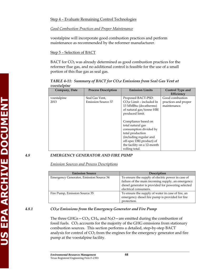
Environmental Resources Management 44 Texas Registered Engineering Firm F-2393
Step 4 – Evaluate Remaining Control Technologies Good Combustion Practices and Proper Maintenance voestalpine will incorporate good combustion practices and perform maintenance as recommended by the reformer manufacturer. Step 5 – Selection of BACT BACT for CO2 was already determined as good combustion practices for the reformer flue gas, and no additional control is feasible for the use of a small portion of this flue gas as seal gas. TABLE 4-11: Summary of BACT for CO2e Emissions from Seal Gas Vent at voestalpine
Company, Date Process Description Emission Limits Control Type and Efficiency
voestalpine 2013
Seal Gas Vent, Emission Source 37
Proposed BACT-PSD: CO2e Limit – included In 13 MMBtu (decatherms) of natural gas/tonne HBI produced limit. Compliance based on total natural gas consumption divided by total production (including regular and off-spec DRI product) of the facility on a 12-month rolling total.
Good combustion practices and proper maintenance.
4.8 EMERGENCY GENERATOR AND FIRE PUMP
Emission Sources and Process Descriptions
Emission Source Description Emergency Generator, Emission Source 34 To ensure the supply of electric power in case of
failure of the main incoming supply, an emergency diesel generator is provided for powering selected electrical consumers.
Fire Pump, Emission Source 35 To ensure the supply of water in case of fire, an emergency diesel fire pump is provided for fire protection.
4.8.1 CO2e Emissions from the Emergency Generator and Fire Pump The three GHGs—CO2, CH4, and N2O—are emitted during the combustion of fossil fuels. CO2 accounts for the majority of the GHG emissions from stationary combustion sources. This section performs a detailed, step-by-step BACT analysis for control of CO2 from the engines for the emergency generator and fire pump at the voestalpine facility.

Environmental Resources Management 45 Texas Registered Engineering Firm F-2393
Step 1 – Identify Potential Control Technologies
A search of USEPA’s RBLC database revealed the following entries for the control of CO2e emissions from emergency engines. Documentation compiled in this research is presented in the table below. TABLE 4-12: Summary of RBLC Data for CO2e Emissions from Emergency Generators and Fire Pumps
RBLC ID Number Company, Date
Process Description Emission Limits Control Type and Efficiency
LA-0256 Westlake Vinyls Company LP Ascension Parish, LA 12/06/11
Emergency Generator, 1818 HP, Natural Gas
BACT-PSD: GHG limit – CO2e 1,509.23 lb/hr, 39.24 tpy.
USE OF NATURAL GAS AS FUEL AND GOOD COMBUSTION PRACTICES.
FL-0328* ENI U.S. Operating Company, Inc. Lloyd Ridge (OCS), FL 10/27/2011 *Draft Determination
Emergency Engine, Diesel
BACT-PSD: GHG Limit – CO2 14.6 tpy, 12-month rolling.
Use of good combustion practices, based on the current manufacturer’s specifications for this engine.
FL-0328* ENI U.S. Operating Company, Inc. Lloyd Ridge (OCS), FL 10/27/2011 *Draft Determination
Emergency Fire Pump Engine, Diesel
BACT-PSD: GHG Limit – CO2 2.4 tpy, 12-month rolling.
Use of good combustion practices, based on the current manufacturer’s specifications for this engine.
LA-0254 Entergy Louisiana LLC LA 08/16/11
Emergency Diesel Generator, 1250 HP
BACT-PSD: GHG Limit – 163 lb/MMBtu, 12-month rolling.
Proper operation and good combustion practices.
LA-0254 Entergy Louisiana LLC LA 08/16/11
Emergency Fire Pump, 350 HP, Diesel
BACT-PSD: GHG Limit – 163 lb/MMBtu, 12-month rolling.
Proper operation and good combustion practices.
TX-0481 Air Products LP Baytown, TX 11/02/04
Emergency Generator BACT-PSD: CO2 Limit - 2.24 lb/hr, 0.99 tpy.
No control specified.
The RBLC database did not identify any add‐on CO2 control technologies for emergency engines; only good combustion practices were identified in the RBLC as BACT for emergency engines. However, the following list of control technologies represent technologies that could be used for the control of GHG emissions from emergency engines.
1. Carbon Capture with Dedicated Sequestration 2. Carbon Capture with Transport and Sequestration 3. Low-Carbon Fuel 4. Good Combustion Practices and Proper Maintenance

Environmental Resources Management 46 Texas Registered Engineering Firm F-2393
Carbon Capture with Dedicated Sequestration Carbon Capture with Dedicated Sequestration CO2 released from the emergency engines is mixed with products of combustion and other inert gases, and is not suitable for sequestration. Carbon Capture with Transport and Sequestration CO2 released from the emergency engines is mixed with products of combustion and other inert gases, and is not suitable for sequestration. Low-Carbon Fuel Using fuels containing lower concentrations of carbon generates less CO2 than other higher carbon fuels. Typically, gaseous fuels such as natural gas contain less carbon, and thus lower CO2 potential, than liquid or solid fuels such as diesel or coal. The use of natural gas as a combustion fuel, in preference over other fossil fuels such as diesel, results in fewer GHG emissions per unit of energy output. This property has been well documented, including through USEPA’s GHG Reporting Rule, which lists natural gas as having the lowest CO2 emission factor of any primary fossil fuel. Natural gas also has benefits over the use of diesel fuel, from the perspective of emissions from other pollutants, such as sulfur dioxide and particulate matter. Good Combustion Practices and Proper Maintenance Good combustion practices for compression ignition engines include appropriate maintenance of equipment (such as periodic testing as will be conducted weekly) and operating within the recommended air to fuel ratio recommended by the manufacturer. Using good combustion practices in conjunction with proper maintenance results in longer life of the equipment and more efficient operation. Therefore, such practices indirectly reduce GHG emissions by supporting operation as designed and with consideration of other energy optimization practices incorporated into the voestalpine facility. Step 2: Eliminate Technically Infeasible Options Carbon Capture with Dedicated Sequestration CO2 released from the emergency engines is mixed with products of combustion and other inert gases, and is not suitable for sequestration. Therefore, carbon capture with dedicated sequestration is not technically feasible and has been eliminated. Also, because the emergency generator and fire pump will normally operate 100 hours per year or less and because their stack gases are low in volume and CO2 mass rate, the capture, and segregation of CO2 for sequestration

Environmental Resources Management 47 Texas Registered Engineering Firm F-2393
is considered a technically infeasible control option for the emergency engines at the voestalpine facility. Carbon Capture with Transport and Sequestration CO2 released from the emergency engines is mixed with products of combustion and other inert gases, and is not suitable for sequestration. Therefore, carbon capture with transport and sequestration is not technically feasible and has been eliminated. Also, because the emergency generator and fire pump will normally operate 100 hours per year or less and because their stack gases are low in volume and CO2 mass rate, the capture, transport, and segregation of CO2 for sequestration is considered a technically infeasible control option for the emergency engines at the voestalpine facility. Low-Carbon Fuel Because the emergency generator and fire pump are intended for emergency use, these engines must be designed to use non‐volatile fuel such as diesel fuel. Use of volatile (low‐carbon) natural gas in an emergency situation could exacerbate a potentially volatile environment that could be present under certain conditions, resulting in unsafe operation. Therefore, non‐volatile fuel is appropriate and necessary for emergency equipment. Therefore, use of low‐carbon fuel is considered technically infeasible for emergency engine operation. Step 3 – Rank Remaining Technically Feasible Control Options
1. Good Combustion Practices and Proper Maintenance (50%)
Step 4 – Evaluate Remaining Control Technologies Good Combustion Practices and Proper Maintenance voestalpine will incorporate good combustion practices and perform maintenance as recommended by the emergency generator and fire pump manufacturers. Step 5: Select BACT A top-down BACT analysis was performed for emissions of CO2e from emergency engines. voestalpine will maintain good combustion practices and proper maintenance for the emergency generator and fire pump to control CO2e emissions. Further, these new engines will be subject to the NSPS for Stationary Compression Ignition Internal Combustion Engines (40 CFR 60 Subpart IIII), and specific emissions standards for various pollutants must be met during normal operation, such that the engines will meet or exceed BACT.

Environmental Resources Management 48 Texas Registered Engineering Firm F-2393
TABLE 4-13 Summary of BACT for CO2e Emissions from Emergency Generator and Fire Pump at voestalpine
Company, Date Process Description Emission Limits Control Type and Efficiency
voestalpine 2013
Emergency Generator, Emission Source 34
Proposed BACT-PSD: CO2e Limit –194 tons CO2e/yr (based on 100 hrs).
Good combustion practices and proper maintenance. Engines must comply with NSPS Subpart IIII based on manufacturer’s specifications.
voestalpine 2013
Fire Pump, Emission Source 35
Proposed BACT-PSD: CO2e Limit –13.8 tons CO2e/yr (based on 100 hrs).
Good combustion practices and proper maintenance. Engines must comply with NSPS Subpart IIII based on manufacturer’s specifications..
4.9 OTHER MEASURES
Terrestrial sequestration involves the fixation of the CO2 into vegetative biomass and soils. For example, trees use CO2 as they grow, and some agricultural practices, such as no-till farming, keep CO2 in the soil (rather than releasing it when the land is tilled). This type of approach is being used in some states, such as Mississippi and other Lower Mississippi Valley states by the US Fish and Wildlife Service (USFWS). The USFWS, in conjunction with company partners and other conservation agencies, has added 40,000 acres of restored habitat to its national wildlife refuges and more than 80,000 acres to native habitats (USFWS, 2010). However, as summarized by the Southwest Regional Partnership for Carbon Sequestration (SWP):
“… terrestrial carbon capacity in the Southwest region is limited by low average annual precipitation and yearly variability in precipitation. Even in systems managed for carbon storage, wet years followed by a series of dry years may result in a net carbon flux out of the system. Opportunity to increase carbon storage on range lands is limited because most areas are at a relatively stable equilibrium given land use history and management. Much of the desert grassland and shrub land areas with less than 12 inches of annual precipitation are subject to loss of cover and exposure to wind and water erosion. Retaining soil carbon levels in these ecosystems will require active restoration practices that are challenging, given current technologies” (SWP, 2012).
Because terrestrial sequestration is unlikely to be effective in Texas, this technology was not evaluated further in this application.

Environmental Resources Management 49 Texas Registered Engineering Firm F-2393
The use of solar collectors or wind turbines to generate energy at DRI plants is potentially feasible, but the existing infrastructure may not be sufficient to supply extra power to the grid. This technology was not evaluated further in this application.

Environmental Resources Management 50 Texas Registered Engineering Firm F-2393
5.0 ADDITIONAL REQUIREMENTS UNDER PSD
An analysis of ambient air quality impacts is not provided with this application as there are no National Ambient Air Quality Standards (NAAQS) or PSD increments established for GHG (per EPA’s PSD and Title V Permitting Guidance for Greenhouse Gases). Since there are no NAAQS or PSD increments for GHGs, the requirements in sections 52.21(k) and 51.166(k) of EPA’s regulations to demonstrate that a source does not cause contribute to a violation of the NAAQS are not applicable to GHGs. Therefore, there is no requirement to conduct dispersion modeling or ambient monitoring for CO2 or GHGs. Additionally, an analysis of Air Quality Related Values (AQRV) is not provided because GHGs do not contribute to regional haze or terrestrial/aquatic acid deposition. A pre-construction monitoring analysis for GHG is not being provided with this application in accordance with EPA’s recommendations (per EPA’s PSD and Title V Permitting Guidance for Greenhouse Gases). EPA does not consider it necessary for applicants to gather monitoring data to assess ambient air quality for GHGs under 40 CFR 52.21(m)(1)(ii), 40 CFR 51.166(m)(1)(ii), or similar provisions that may be contained in state rules based on EPA’s rules. GHGs do not affect “ambient air quality” in the sense that EPA intended when these parts of EPA’s rules were initially drafted. Considering the nature of GHG emissions and their global impacts, EPA does not believe it is practical or appropriate to expect permitting authorities to collect monitoring data for purpose of assessing ambient air impacts of GHGs A PSD application for the criteria pollutants is being submitted to the Texas Commission for Environmental Quality (TCEQ) under separate cover. Impact evaluations related to the Federal Endangered Species Act (biological assessment) and the National Historic Preservation Act (cultural assessment) are being submitted to USEPA under separate cover.

Environmental Resources Management 51 Texas Registered Engineering Firm F-2393
REFERENCES Bellona, 2012. “CCS in Industry.” Bellona Environmental CCS Team. Available
on-line at: http://bellona.org/ccs/technology/ccs-in-industry-plants.html.
European Integrated Pollution Prevention and Control Bureau (EIPPCB), 2012.
Best Available Techniques (BAT) Reference Document for Iron and Steel Production Industrial Emissions. Directive 2010/75/EU (Integrated Pollution Prevention and Control). Joint Research Centre Institute for Prospective Technological Studies Sustainable Production and Consumption Unit, Brussels, Belgium, November 2012.
Global CCS Institute, 2011. The Global Status of CCS: 2011. Global CCS Institute,
Canberra, Australia, September 2011. Global CCS Institute, 2012. The Global Status of CCS: 2012. Global CCS Institute,
Canberra, Australia, September 2012. Hallerman, Tamar, 2012a. “Two of DOE’S Industrial CCS Projects Nearing
Operations Phase,” in the GHG Monitor. Available on-line at: http://ghgnews.com/index.cfm/two-of-doee28099s-industrial-ccs-projects-nearing-operations-phase/.
Hallerman, Tamar, 2012b. “Summit Prepares Rollout of Two More TX CCS
Projects Following TCEP Model,” in the GHG Monitor. Available on-line at: http://ghgnews.com/index.cfm/summit-prepares-rollout-of-two-more-tx-ccs-projects-following-tcep-model/.
Interagency Task Force on Carbon Capture (2010). Report of the Interagency Task Force
on Carbon Capture and Storage. August 2010. IEA, 2007. Tracking Industrial Energy Efficiency and CO2 Emissions. International
Energy Agency, Head of Communication and Information Office, Paris, France, 2007.
Midrex, 2012. “Revisiting the Carbon Issue: Reducing the World Steel Industry’s
Carbon Footprint through Direct Reduction and CCS,” in Direct from Midrex, 1st Quarter 2012. Available on-line at: http://www.midrex.com/handler.cfm/cat_id/152/section/company.
SWP, 2012. “Southwest Partnership CO2 Sequestration,” NETL, April 2009.
Available on-line at: southwestcarbonpartnership.org/Terrestrial_Carbon_Sequequestration_FactSheet.pdf.
UNIDO, 2010. Carbon Capture and Storage in Industrial Applications: Technology
Synthesis Report, Working Paper. United Nations Industrial Development

Environmental Resources Management 52 Texas Registered Engineering Firm F-2393
Organization, Vienna, Austria, November 2010. Available on-line at: http://www.globalccsinstitute.com/publications/carbon-capture-and-storage-industrial-applications-technology-synthesis-report.
USEPA, 1990. Draft New Source Review Workshop Manual. United States
Environmental Protection Agency, Office of Air Quality Planning and Standards, Research Triangle Park, NC, March 1990. Available on-line at: www.epa.gov/ttn/nsr/gen/wkshpman.pdf.
USEPA, 2010. Available and Emerging Technologies for Reducing Greenhouse Gas
Emissions from the Portland Cement Industry. Office of Air Quality Planning and Standards, Sector Policies and Programs Division, Research Triangle Park, NC, October 2010.
USEPA, 2011. PSD and Title V Permitting Guidance for Greenhouse Gases, EPA-
457/B-11-001. Office of Air Quality Planning and Standards, Air Quality Policy Division, Research Triangle Park, NC, March 2011. Available on-line at: www.epa.gov/nsr/ghgdocs/ghgpermittingguidance.pdf.
USEPA, 2012. Available and Emerging Technologies for Reducing Greenhouse Gas
Emissions from the Iron and Steel Industry. Office of Air Quality Planning and Standards, Sector Policies and Programs Division, Research Triangle Park, NC, September 2012.
USFWS, 2010. Carbon Sequestration Fact Sheet. Atlanta, GA: US Fish and Wildlife
Service, April 2010. Available online at: http://www.fws.gov/southeast/carbon/pdf/CarbonFactSheet.pdf

Appendix A
Emission Rate Calculations

SUMMARY TABLE: voestalpine Direct Reduction Iron Facility Emissions Totals
Environmental Resources Management
Emission Point ID
Modeling Stack No. Air Emission Source Description
Average lb/hr
Average tons/yr
Average lb/hr
Average tons/yr
Average lb/hr
Average tons/yr
Average lb/hr
Average tons/yr
1 1 Dock Ore Unloading / Product Loading Gantry Crane 0.42 1.84 0.20 0.87 0.03 0.13
4 4 Oxide Unloading Bin & Dedusting 0.11 0.49 0.11 0.49 0.08 0.36
5 5 Oxide Pellet Pile Transfer & Dedusting (Pre Pile) 0.25 1.10 0.25 1.10 0.19 0.83
2 2 Oxide Pellets Piles 1 2.00 8.75 0.51 2.23 0.09 0.38
6 6 Oxide Transfer & Dedusting (Post Pile) 0.11 0.49 0.11 0.49 0.08 0.36
7 7 Oxide & Remet Screening & Dedusting 0.71 3.09 0.71 3.09 0.53 2.32
16 16 Furnace Charge Hopper Loading Silos 0.01 <0.01 0.01 <0.01 0.01 <0.01
29 29 Reformer Main Flue Ejector Stack 7.41 32.46 7.41 32.46 7.41 32.46 81.52 357.06
38 38 Hot Pressure Relief Vent (Flare) 0.51 0.08 0.51 0.08 0.51 0.08 20.26 2.96
37 37 Seal Gas Vent 0.37 1.61 0.37 1.61 0.37 1.61 4.22 18.48
8 8 Furnace Dedusting (BSG Dust Collection) 2.50 10.95 2.50 10.95 2.25 9.86
9 9 Briquetter Dedusting 3.97 17.38 3.97 17.38 3.57 15.64
12 12 Transfer & Product Screening Station No. 1 (Pre Pile) 0.40 1.77 0.40 1.77 0.36 1.59
14 14 Product Storage Piles 1.48 6.50 0.44 1.91 0.07 0.30
13 13 Transfer & Product Screening Station No. 2 (Post Pile) 0.40 1.77 0.40 1.77 0.36 1.59
36 36 Remet / Fines Storage 0.17 0.74 0.04 0.20 0.01 0.02
33 33 Salt Water Cooling Tower 2.61 11.44 0.08 0.34 0.08 0.34
39 39 Paved Road Fugitive Dust 0.25 1.08 0.05 0.21 0.01 0.03
34 34 Emergency Generator 0.47 0.02 0.47 0.02 0.47 0.02 32.09 1.60
35 35 Fire Pump 0.03 <0.01 0.03 <0.01 0.03 <0.01 2.25 0.11
24.18 101.54 18.57 76.95 16.51 67.93 140.33 380.22TOTAL EMISSIONS
TSP Emissions PM10 Emissions PM2.5 Emissions NOx Emissions

SUMMARY TABLE: voestalpine Direct Reduction Iron Facility Emissions Totals
Environmental Resources Management
Emission Point ID
Modeling Stack No. Air Emission Source Description
1 1 Dock Ore Unloading / Product Loading Gantry Crane
4 4 Oxide Unloading Bin & Dedusting
5 5 Oxide Pellet Pile Transfer & Dedusting (Pre Pile)
2 2 Oxide Pellets Piles 1
6 6 Oxide Transfer & Dedusting (Post Pile)7 7 Oxide & Remet Screening & Dedusting
16 16 Furnace Charge Hopper Loading Silos
29 29 Reformer Main Flue Ejector Stack
38 38 Hot Pressure Relief Vent (Flare)
37 37 Seal Gas Vent
8 8 Furnace Dedusting (BSG Dust Collection)
9 9 Briquetter Dedusting
12 12 Transfer & Product Screening Station No. 1 (Pre Pile)
14 14 Product Storage Piles
13 13 Transfer & Product Screening Station No. 2 (Post Pile)
36 36 Remet / Fines Storage
33 33 Salt Water Cooling Tower39 39 Paved Road Fugitive Dust
34 34 Emergency Generator35 35 Fire Pump
TOTAL EMISSIONS
Average lb/hr
Average tons/yr
Average lb/hr
Average tons/yr
Average lb/hr
Average tons/yr
Average lb/hr
Average tons/yr
2.76 8.46 109.98 481.72 7.20 31.54 <0.01 <0.01
0.02 <0.01 248.93 33.02 0.04 0.02
0.14 0.60 5.44 23.85 <0.01 <0.01
0.04 <0.01 3.80 0.19 0.99 0.05
<0.01 <0.01 0.27 0.01 0.07 <0.01
2.96 9.06 368.42 538.80 8.30 31.61 <0.01 <0.01
CO Emissions VOC EmissionsSO2 Emissions Benzene

SUMMARY TABLE: voestalpine Direct Reduction Iron Facility Emissions Totals
Environmental Resources Management
Emission Point ID
Modeling Stack No. Air Emission Source Description
1 1 Dock Ore Unloading / Product Loading Gantry Crane
4 4 Oxide Unloading Bin & Dedusting
5 5 Oxide Pellet Pile Transfer & Dedusting (Pre Pile)
2 2 Oxide Pellets Piles 1
6 6 Oxide Transfer & Dedusting (Post Pile)7 7 Oxide & Remet Screening & Dedusting
16 16 Furnace Charge Hopper Loading Silos
29 29 Reformer Main Flue Ejector Stack
38 38 Hot Pressure Relief Vent (Flare)
37 37 Seal Gas Vent
8 8 Furnace Dedusting (BSG Dust Collection)
9 9 Briquetter Dedusting
12 12 Transfer & Product Screening Station No. 1 (Pre Pile)
14 14 Product Storage Piles
13 13 Transfer & Product Screening Station No. 2 (Post Pile)
36 36 Remet / Fines Storage
33 33 Salt Water Cooling Tower39 39 Paved Road Fugitive Dust
34 34 Emergency Generator35 35 Fire Pump
TOTAL EMISSIONS
Average lb/hr
Average tons/yr
Average lb/hr
Average tons/yr
Average lb/hr
Average tons/yr
Average lb/hr
Average tons/yr
<0.01 <0.01 0.01 0.05 0.28 1.24 <0.01 <0.01
<0.01 <0.01 <0.01 <0.01 0.01 0.06 <0.01 <0.01
<0.01 <0.01 0.01 0.05 0.30 1.30 <0.01 <0.01
NaphthaleneDichlorobenzene Formaldehyde n-Hexane
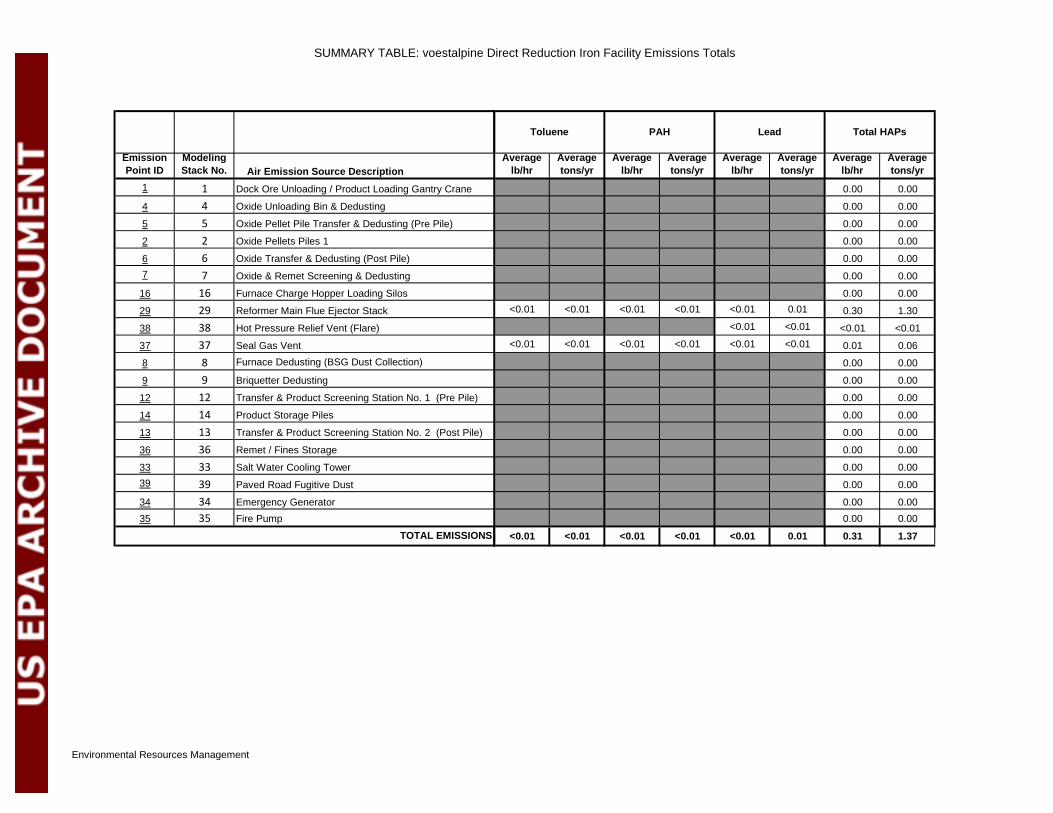
SUMMARY TABLE: voestalpine Direct Reduction Iron Facility Emissions Totals
Environmental Resources Management
Emission Point ID
Modeling Stack No. Air Emission Source Description
1 1 Dock Ore Unloading / Product Loading Gantry Crane
4 4 Oxide Unloading Bin & Dedusting
5 5 Oxide Pellet Pile Transfer & Dedusting (Pre Pile)
2 2 Oxide Pellets Piles 1
6 6 Oxide Transfer & Dedusting (Post Pile)7 7 Oxide & Remet Screening & Dedusting
16 16 Furnace Charge Hopper Loading Silos
29 29 Reformer Main Flue Ejector Stack
38 38 Hot Pressure Relief Vent (Flare)
37 37 Seal Gas Vent
8 8 Furnace Dedusting (BSG Dust Collection)
9 9 Briquetter Dedusting
12 12 Transfer & Product Screening Station No. 1 (Pre Pile)
14 14 Product Storage Piles
13 13 Transfer & Product Screening Station No. 2 (Post Pile)
36 36 Remet / Fines Storage
33 33 Salt Water Cooling Tower39 39 Paved Road Fugitive Dust
34 34 Emergency Generator35 35 Fire Pump
TOTAL EMISSIONS
Average lb/hr
Average tons/yr
Average lb/hr
Average tons/yr
Average lb/hr
Average tons/yr
Average lb/hr
Average tons/yr
0.00 0.00
0.00 0.00
0.00 0.00
0.00 0.00
0.00 0.00
0.00 0.00
0.00 0.00<0.01 <0.01 <0.01 <0.01 <0.01 0.01 0.30 1.30
<0.01 <0.01 <0.01 <0.01<0.01 <0.01 <0.01 <0.01 <0.01 <0.01 0.01 0.06
0.00 0.00
0.00 0.00
0.00 0.00
0.00 0.00
0.00 0.00
0.00 0.00
0.00 0.00
0.00 0.00
0.00 0.000.00 0.00
<0.01 <0.01 <0.01 <0.01 <0.01 0.01 0.31 1.37
Toluene PAH Lead Total HAPs

Environmental Resources Management Source ID 1
Emission Point Source Calculations
Case: 1Description: Dock Ore Unloading / Product Loading Gantry Crane
Inputs Value UnitsAnnual hours of operation 8,760 hrs/yrMaximum Loading Rate (Conveyor Capacity) 1,500 tons/hr Average wind speed 12.0 mphLoading control efficiency 90.0% %Unloading control efficiency 90.0% %Annual throughput - iron ore 3,197,250 tons/yrExcess Receiving Capacity (Annual) 110% %Conveyor System Service Factor (Hourly) 115% %Material moisture content-iron ore 3.20 %
Emissions Summary
Source Description Pollutant Average Emission
Rate
Annual Emission
Rate(lbs/hr) (tpy)
TSP* 0.419 1.84PM10 0.198 0.868PM2.5 0.0300 0.131
* Per AP-42 (Table 13.2.2-2), PM-30 is assumed equivalent to total suspended particle matter (TSP)
Calculation Basis:
Loading emissions: (1) conveyor to ship/barge (i.e., 1 drop)Unloading emissions: (1) ship/barge via gantry grab crane to hopper, (2) hopper to receiving conveyor (2 drops)
Barge/Ship Unloading (Dock 1)
4.1
3.1
5*)0032.0(*)/(
=M
U
ktonlbfactorEmission

Environmental Resources Management Source ID 1
Emission Factor (lb PM / ton handled)*
< 30 micrometers 0.74where U = Mean wind speed (mph) for the area 1 < 15 micrometers 0.48
M = Material moisture content (%)2 < 10 micrometers 0.35k = Particle size multiplier 3 < 5 micrometers 0.2
< 2.5 micrometers 0.053
Note: 1. Corpus Christi average wind speed (previous 60 years) http://www.ncdc.noaa.gov/oa/climate/online/ccd/avgwind.html2. From AP-42 (11/06), Section 13.2.4.2, Table 13.2.4-1 and process experience3. From AP-42 (11/06), Section 13.2.4.3
* Calculation methodology derived from Section 13.2.4 "Aggregate Handling and Storage Piles ," AP-42 (11/06).
Emission Calculations
Average Controlled Emission Rate (tons/yr) = Material Throughput (tons/yr) * EF (lb PM/ton) * (Number of drops) * (1-Control efficiency)Average Controlled Emission Rate (lb/hr) = Average Controlled Emission Rate (tons/yr)* (2000 lb/ton)/8760 hrs/yr
Particulate Emissions from Barge Loading/Unloading @ Dock # 1
Pollutant Annual Throughput Emission Factor
Number of Drops
Uncontrolled Emissions
Overall Control
Efficiency
Excess Receiving Capacity
Conveyor Service Factor
Average Emission
Rate
Annual Emission
Rate(tons/yr1) (lb/ton) (lb/yr) % % % (lb/hravg) (tpy)
TSP 3,197,250 0.00383 3.00 36,710 90.0% 110% 115% 0.419 1.84PM10 3,197,250 0.00181 3.00 17,363 90.0% 110% 115% 0.198 0.868PM2.5 3,197,250 0.000274 3.00 2,629 90.0% 110% 115% 0.0300 0.1311 Capacity converted to US tons2 Pig iron has no intrinsic silt content, and is assumed to be non-emitting.
Aerodynamic Particle Size Multiplier (k)
2
M

Environmental Resources Management Source ID 4
Emission Point Source Calculations
Emission Point Identifier: 4Description: Oxide Unloading Bin & Dedusting
InputsDescription Value UnitsAnnual Hours of Operation 8,760 hr/yrIron Oxide Consumption Rate 3,197,250 tons/yrDesign Volmetric Vent Rate 11,000 Nm3/hrClean Gas Concentration 4.57 mg/Nm3
PM10 Mass Fraction 100% %PM2.5 Mass Fraction (uncontrolled 15%, AP-42) 75.0% %
Emissions Summary
Pollutant
Average Emission
Rate(lb/hr)
Annual Emission
Rate(tpy)
TSP 0.111 0.485PM10 0.111 0.485PM2.5 0.0831 0.364
Calculate Emissions
Pollutant
Normal Dedusting
Airflow Rate
Maximum Clean Gas Concentrat
ion
Mass Fraction of Total PM
Average Emission
Rate
Annual Emission
Rate
(Nm3/hr) (mg/Nm3) % (lb/hr) (tons/yr)TSP 11,000 4.57 100% 0.111 0.485PM10 11,000 4.57 100% 0.111 0.485PM2.5 11,000 4.57 75.0% 0.0831 0.364

Environmental Resources Management Source ID 5
Emission Point Source Calculations
Emission Point Identifier: 5Description: Oxide Pellet Pile Transfer & Dedusting (Pre Pile)
InputsDescription Value UnitsAnnual Hours of Operation 8,760 hr/yrIron Oxide Consumption Rate 3,197,250 tons/yrDesign Volmetric Vent Rate 25,000 Nm3/hrClean Gas Concentration 4.57 mg/Nm3
PM10 Mass Fraction 100% %PM2.5 Mass Fraction (uncontrolled 15%, AP-42) 75.0% %
Emissions Summary
PollutantAverage
Emission Rate(lb/hr)
Annual Emission
Rate(tpy)
TSP 0.25 1.10PM10 0.25 1.10PM2.5 0.19 0.83
Calculate Emissions
Pollutant
Normal Dedusting
Airflow Rate
Maximum Clean Gas
Concentration
Mass Fraction of Total PM
Average Emission
Rate
Annual Emission
Rate
(Nm3/hr) (mg/Nm3) % (lb/hr) (tons/yr)TSP 25,000 4.57 100% 0.25 1.10PM10 25,000 4.57 100% 0.25 1.10PM2.5 25,000 4.57 75.0% 0.19 0.83

Environmental Resources Management Source ID 2
Emission Point Source Calculations
Case: 2Description: Oxide Pellets Piles 1
Inputs Value UnitsMaterial storage time 8,760 hrsStorage duration 365 daysAverage wind speed 12.0 mphNumber of dry days per year 288 daysPercentage of time wind speed > 12 mph 50.0% % (actual)Annual Material Throughput 3,197,250 tons/yrExcess Receiving Capacity (Annual) 110% %Transfer rate-stacker 1,500 tons/hrTransfer rate-reclaimer 1,500 tons/hrWind Erosion Chemical Suppression 95.0% %Control efficiency -stacker 90.0% %Control efficiency -reclaimer 75.0% %Material moisture content 3.00 %Material silt content 15.00 %Storage area ground surface silt content 6.00 %Percentage PM 10 in material 6.0% %Pile maintenance/traffic hours 365 daysDozer miles per day 2 miDozer average weight 20 tonsFront end loader miles per day 10 miFront end loader average weight 20 tonsControl efficiency - maintenance/traffic 70.0% %Corpus Christi average wind speed (previous 60 years) http://www.ncdc.noaa.gov/oa/climate/online/ccd/avgwind.html, 7/27/12Corpus Christi mean number of days with precipitation .01" or more (previous 63 years) http://lwf.ncdc.noaa.gov/oa/climate/online/ccd/prcpdays.html, 7/27/12http://www.ncdc.noaa.gov/oa/climate/online/ccd/avgwind.html
Emissions Summary
Total Suspended Particles (TSP) Source Description Average
Emission RateAnnual Emission
Rate
(lbs/hr) (tpy)Material Transfers In/Out of Storage 0.371 1.63Equipment Traffic in Storage Area 1.17 5.12Wind Erosion 0.457 2.003
TOTAL 2.00 8.75

Environmental Resources Management Source ID 2
Total Particulate Matter < 10 um (PM10)
Source Description Average Emission Rate
Annual Emission Rate
(lbs/hr) (tpy)Material Transfers In/Out of Storage 0.170 0.745Equipment Traffic in Storage Area 0.311 1.36Wind Erosion 0.0274 0.1202
TOTAL 0.509 2.23
Total Particulate Matter < 2.5 um (PM2.5)
Source Description Average Emission Rate
Annual Emission Rate
(lbs/hr) (tpy)Material Transfers In/Out of Storage 0.0526 0.230Equipment Traffic in Storage Area 0.0311 0.136Wind Erosion 0.00412 0.0180
TOTAL 0.0878 0.385
1Per AP-42 (Table 13.2.2-2), PM-30 is assumed equivalent to toal suspended particle matter (TSP)
Material Stacking and Reclaiming
Calculation Basis:
Calculation methodology derived from Table 12.5-4 "Pile Formation, Stacker, Pellet Ore, " AP-42 (10/86).Transfer Locations: (1) stacker/dump to pile; (2) reclaimer/loader out of pile onto conveyor; (3) equipment traffic within pile area.
Emission Calculations
Average Annual Particulate (TSP) Emissions from Material Storage Pile Transfers
Transfer Location Annual Throughput Emission Factor Number of
DropsUncontrolled
EmissionsOverall Control
Efficiency Controlled Emission Rates
(tons/yr1) (lb/ton) (lb/yr) % (lb/hravg) (tpy)Storage Pile (stacker) 3,517,327 0.00240 1.00 8,442 90.0% 0.0964 0.422Storage Pile (reclaimer) 3,517,327 0.00240 1.00 8,442 75.0% 0.241 1.055TOTAL 0.337 1.477
Average Annual Particulate (PM10) Emissions from Material Storage Pile Transfers
Transfer Location Annual Throughput Emission Factor Number of
DropsUncontrolled
EmissionsOverall Control
Efficiency Controlled Emission Rates
(tons/yr1) (lb/ton) (lb/yr) % (lb/hravg) (tpy)Storage Pile (stacker) 3,517,327 0.00110 1.00 3,869 90.0% 0.0442 0.193Storage Pile (reclaimer) 3,517,327 0.00110 1.00 3,869 75.0% 0.1104 0.484TOTAL 0.1546 0.677

Environmental Resources Management Source ID 2
Average Annual Particulate (PM2.5) Emissions from Material Storage Pile Transfers
Transfer Location Annual Throughput Emission Factor Number of
DropsUncontrolled
EmissionsOverall Control
Efficiency Controlled Emission Rates
(tons/yr1) (lb/ton) (lb/yr) % (lb/hravg) (tpy)Storage Pile (stacker) 3,517,327 0.000340 1.00 1,196 90.0% 0.01365 0.0598Storage Pile (reclaimer) 3,517,327 0.000340 1.00 1,196 75.0% 0.0341 0.1495TOTAL 0.0478 0.209
1 capacity converted to US tons
Equipment Traffic in Storage Areas
Calculation Basis:
Calculation methodology derived from Section 13.2.2, "Unpaved Roads, " dated AP-42 (11/06) (in accordance with guidance from Section 13.2.4)Accounts for bulldozer (on pile) and front-end loader (between piles)
Emission factor (lb/VMT) = k(s/12) a (W/3) b
where: s = silt content of aggregate (%)1 Empirical Constants for Industrial RoadsW = mean vehicle weight 2 PM-2.5 PM-10 PM-30k,a, b = empirical constants for industrial roads 3 k 0.15 1.5 4.9
a 0.9 0.9 0.70b 0.45 0.45 0.45
Note: 1. From AP42, Section 13.2.2, Table 13.2.2-1, Dated 11/062. From AP42, Section 13.2.2, Table 13.2.2-3, Dated 11/063. From AP42, Section 13.2.2, Table 13.2.2-2, Dated 11/06
Calculation of Average Annual Controlled Emission Rate
Average Annual Controlled Emission Rate (tons/yr) = Vehicle Miles traveled in an day (VMT/day) * EF (lb PM / VMT ) * (number of days per year)*(1-control efficiency) / (2000 lb/ton)
Average Controlled Emission Rate (lb/hr) = Average Controlled Emission Rate (tons/yr)* (2000 lb/ton)/8760 hrs/yr

Environmental Resources Management Source ID 2
Emission Calculations:
Average Annual Particulate Emissions (TSP) from Equipment Traffic in Storage Areas
Vehicle Type Vehicle Miles Traveled Emission Factor Uncontrolled
Emission RateOverall Control
Efficiency Controlled Emission Rates
(VMT/day) (lb/VMT) (lb/day) % (lb/hravg) (tpy)Dozers 2 7.08 14.2 70.0% 0.177 0.776Front-end loaders 10 7.08 70.8 70.0% 0.885 3.88TOTAL 1.06 4.65
Average Annual Particulate Emissions (PM10) from Equipment Traffic in Storage Areas
Vehicle Type Vehicle Miles Traveled Emission Factor Uncontrolled
Emission RateOverall Control
Efficiency Controlled Emission Rates
(VMT/day) (lb/VMT) (lb/day) % (lb/hravg) (tpy)Dozers 2 1.89 3.78 70.0% 0.0472 0.207Front-end loaders 10 1.89 18.9 70.0% 0.236 1.03TOTAL 0.283 1.24
Average Annual Particulate Emissions (PM2.5) from Equipment Traffic in Storage Areas
Vehicle Type Vehicle Miles Traveled Emission Factor Uncontrolled
Emission RateOverall Control
Efficiency Controlled Emission Rates
(VMT/day) (lb/VMT) (lb/day) % (lb/hravg) (tpy)Dozers 2 0.189 0.378 70.0% 0.00472 0.0207Front-end loaders 10 0.189 1.89 70.0% 0.0236 0.103TOTAL 0.0283 0.124

Environmental Resources Management Source ID 2
Wind Erosion
Calculation Basis:
Calculation methodology derived from EPA documents: "Fugitive Emissions from Integrated Iron and Steel Plants ", Section 2.2.4, Figure 3-9 (March 1978) and "Iron and Steel Plant Open Source Fugitive Emission Evaluation ", Section 2.1.3 and Table 2-1, Equation (8) (August 1978)Climatological data NOAA Website for Corpus Christi TX
Emission factor (lb/ton) = 0.05(s/1.5)(D/90)(d/235)(f/15)
where: s = silt content of aggregate (%)1
D = duration of storage (days)d = dry days per year2
f = percentage of time wind speed exceeds 12 mph
Note: 1. From AP42, Section 13.2.2, Table 13.2.2-1, Dated 11/062. From AP42, Section 13.2.2, Table 13.2.2-1, Dated 11/06
Calculation of Average Annual Controlled Emission Rate
Average Annual Controlled Emission Rate (tons/yr) = tons of aggregate through storage cycle (tons) * EF (lb PM / VMT ) * (1 - Control efficiency)Average Controlled Emission Rate (lb/hr) = Average Controlled Emission Rate (tons/yr)* (2000 lb/ton)/8760 hrs/yr
Emission Calculations:
Average Annual Particulate Emissions (TSP) from Wind Erosion from Storage Piles
Aggregate Throughput1 Emission Factor Uncontrolled Rate
Overall Control Efficiency Controlled Emission Rate
(tons/yr) (lb/ton) (lb/yr) % (lb/hravg) (tpy)Iron Ore Pellets 879,332 0.0828 72,841.1 95.0% 0.416 1.821
Average Annual Particulate Emissions (PM10) from Wind Erosion from Storage PilesAggregate TSP Controlled Emission Rate % PM 10 Controlled Emission Rate
(lb/hravg) (tpy) % (lb/hravg) (tpy)Iron Ore Pellets 0.416 1.821 6.0% 0.0249 0.1093
Average Annual Particulate Emissions (PM2.5) from Wind Erosion from Storage PilesAggregate TSP Controlled Emission Rate % PM2.5
2 Controlled Emission Rate(lb/hravg) (tpy) % (lb/hravg) (tpy)
Iron Ore Pellets 0.416 1.821 0.90% 0.00374 0.0164
1 Assume 3-month supply onsite at all times2 Per an EPA document showing that PM2.5/PM10 for metallic ore and coal piles is 0.15- www.epa.gov/ttn/chief/conference/ei15/session14/cowherd.pdf

Environmental Resources Management Source ID 6
Emission Point Source Calculations
Emission Point Identifier: 6Description: Oxide Transfer & Dedusting (Post Pile)
InputsDescription Value UnitsAnnual Hours of Operation 8,760 hr/yrIron Oxide Consumption Rate 3,197,250 tons/yrDesign Volmetric Vent Rate 11,000 Nm3/hrClean Gas Concentration 4.57 mg/Nm3
PM10 Mass Fraction 100% %PM2.5 Mass Fraction (uncontrolled 15%, AP-42) 75.0% %
Emissions Summary
PollutantAverage
Emission Rate(lb/hr)
Annual Emission
Rate(tpy)
TSP 0.111 0.485PM10 0.111 0.485PM2.5 0.0831 0.364
Calculate Emissions
Pollutant
Normal Dedusting
Airflow Rate
Maximum Clean Gas
Concentration
Mass Fraction of Total PM
Average Emission
Rate
Annual Emission
Rate
(Nm3/hr) (mg/Nm3) % (lb/hr) (tons/yr)TSP 11,000 4.57 100% 0.111 0.485PM10 11,000 4.57 100% 0.111 0.485PM2.5 11,000 4.57 75.0% 0.0831 0.364

Environmental Resources Management Source ID 7
Emission Point Source Calculations
Emission Point Identifier: 7Description: Oxide & Remet Screening & Dedusting
InputsDescription Value UnitsAnnual Hours of Operation 8,760 hr/yrDesigned Production Rate 3,197,250 tons/yrDesign Volmetric Vent Rate 70,000 Nm3/hrClean Gas Concentration 4.57 mg/Nm3
PM10 Mass Fraction 100% %PM2.5 Mass Fraction (uncontrolled 15%, AP-42) 75.0% %
Emissions Summary
Pollutant
Average Emission
Rate(lb/hr)
Annual Emission
Rate(tpy)
TSP 0.705 3.09PM10 0.705 3.09PM2.5 0.529 2.32
Calculate Emissions
Pollutant
Normal Dedusting
Airflow Rate
Maximum Clean Gas Concentrat
ion
Mass Fraction of Total PM
Average Emission
Rate
Annual Emission
Rate
(Nm3/hr) (mg/Nm3) % (lb/hr) (tons/yr)TSP 70,000 4.57 100% 0.705 3.09PM10 70,000 4.57 100% 0.705 3.09PM2.5 70,000 4.57 75.0% 0.529 2.32

Environmental Resources Management Source ID 16
Emission Point Source Calculations
Emission Point Identifier: 16Description: Furnace Charge Hopper Loading SilosInputsDescription Value UnitsAnnual Hours of Operation 364 hr/yrDesigned Production Rate 3,197,250 tons/yrDesign Volmetric Vent Rate 1,400 Nm3/hrGas Dust Loading 4.57 mg/Nm3
PM10 Mass Fraction 100% %PM2.5 Mass Fraction (uncontrolled 15%, AP-42) 75.0% %
Emissions Summary
Pollutant
Average Emission
Rate(lb/hr)
Annual Emission
Rate(tpy)
TSP 0.0141 0.00257PM10 0.0141 0.00257PM2.5 0.0106 0.00193
Calculate Emissions
Pollutant
Normal Dedusting
Airflow Rate
Maximum Clean gas
Dust Loading
Mass Fraction of Total PM
Average Emission
Rate
Annual Emission
Rate
(Nm3/hr) (mg/Nm3) % (lb/hr) (tons/yr)TSP 1,400 4.57 100% 0.0141 0.00257PM10 1,400 4.57 100% 0.0141 0.00257PM2.5 1,400 4.57 75.0% 0.0106 0.00193

Environmental Resources Management Source ID 29
Emission Point Source Calculations
Emission Point Identifier: 29Description: Reformer Main Flue Ejector Stack
InputsDescription Value Units CommentsAnnual Hours of Operation 8,760 hr/yrDesigned Production Rate, Annual 2,205,000 tons/yr ManfacturerDesigned Production Rate, Hourly 360 ton HBI / hr ManfacturerMaximum Production Rate Ratio 110% % Design MaximumTotal Reformer Vented Rate, wet @ 1.49% O2 424,000 Nm3/hr Design MaximumSeal Gas System Off-take 20,000 Nm3/hr ManfacturerNormal Reformer Firing Rate 1,402 MMBtu/hr Main and Aux burners plus Top GasNominal Natural Gas Supplement Rate 12.0% % MaufacturerTotal PM Emission Factor, dry @3%O2 10.0 mg/Nm3 Vendor Guarantee, totalFilterable PM Emission Factor 25.0% % AP-42, Chapter 1, Section 4NOX Uncontrolled Concentration, dry at 3% O2 110.0 mg/Nm3
Vendor Guarantee, totalPM10 Filterable Mass Fraction 100% Worst casePM2.5 Filterable Mass Fraction 100% Worst caseCO Emission Factor 84.0 lbs / mmft3 AP-42, Chapter 1, Section 4, Table 1.4-1CO2 Emission Factor 120,000 lbs / mmft3 AP-42, Chapter 1, Section 4, Table 1.4-2SO2 Emission Factor 0.600 lbs / mmft3 AP-42, Chapter 1, Section 4, Table 1.4-2VOC Emission Factor 5.50 lbs / mmft3 AP-42, Chapter 1, Section 4, Table 1.4-2Natural Gas, fuel and reduction gas raw materials 380 Nm3/ton HBI Manfacturer, total

Environmental Resources Management Source ID 29
Emissions Summary
PollutantAverage
Emission Rate(lb/hr)
Annual Emission
Rate(tpy)
TSP 7.41 32.5PM10 7.41 32.5PM2.5 7.41 32.5NOx 81.5 357SO2 2.76 8.5CO 110 482CO2 552,385 1,691,680CO2e 552,510 1,692,060VOC 7.20 31.5Lead (Pb) 2.30E-03 7.05E-03Benzene 3.30E-04 1.44E-03Dichlorobenzene 1.88E-04 8.25E-04Formaldehyde 0.0118 0.0516n-Hexane 0.282 1.24Naphthalene 9.57E-05 4.19E-04Toluene 5.34E-04 2.34E-03PAH 1.32E-05 5.77E-05
Calculate EmissionsVia Outlet Concentrations (Manufacutrer)
PollutantNormal
Vented Flue Flow Rate
Dry Vented Flue Flow Rate
Component Concentration
@ 3% O2
Control Efficiency
Average Emission Rate
Annual Emission Rate
(Nm3/hr) (dNm3/hr) (mg/dNm3) % (lb/hr) (tons/yr)NOx 404,000 316,696 110.0 0% 81.5 357TSP 404,000 316,696 10.0 0% 7.41 32.5PM10 404,000 316,696 10.0 0% 7.41 32.5PM2.5 404,000 316,696 10.0 0% 7.41 32.5Emission rate correction to 3% O2: dNm3 * mg/dNm3 / 453600 * ((20.9-1.9)/(20.9-3))

Environmental Resources Management Source ID 29
Via AP-42 Emission Factor, Chapter 1, Section 4, Tables 1.4-1 and 1.4-2
PollutantNormal
Reformer Firing Rate
Emission Factor Control Efficiency
Seal Gas Compensation
Average Emission Rate
Annual Emission Rate
(MMBtu/hr) (lbs/mmBtu NG) % - (lb/hr) (tons/yr)CO 1,402 0.0824 0% 0.953 110.0 482VOC 1,402 0.00539 0% 0.953 7.20 31.5
Via Reducing Gas and Fuel Maximum
PollutantTotal NG as
Fuel and Raw Material
Emission Factor Control Efficiency
Seal Gas Compensation
Average Emission Rate
Annual Emission Rate
(Nm3/ton) (ton HBI/hr) (ton HBI/yr) (lbs/mmcf NG) % - (lb/hr) (tons/yr)SO2 380 360 2,205,000 0.600 0% 0.953 2.76 8.5CO2 380 360 2,205,000 120,000 0% 0.953 552,385 1,691,680CO2e 380 360 2,205,000 120,027 0% 0.953 552,510 1,692,060Lead (Pb) 380 360 2,205,000 5.00E-04 0% 0.953 2.30E-03 0.0070
Calculate HAP Emissions
PollutantNormal
Reformer Firing Rate
AP-42 Emission Factor
Nominal Natural Gas
Supplement Rate
Seal Gas System
Compensation
Average Emission Rate
Annual Emission Rate
(MMBtu/hr) (lb/MBtu) % (-) (lb/hr) (tons/yr)Benzene 1,402 2.06E-06 12.0% 0.953 3.30E-04 1.44E-03Dichlorobenzene 1,402 1.18E-06 12.0% 0.953 1.88E-04 8.25E-04Formaldehyde 1,402 7.35E-05 12.0% 0.953 1.18E-02 5.16E-02n-Hexane 1,402 1.76E-03 12.0% 0.953 2.82E-01 1.24E+00Naphthalene 1,402 5.98E-07 12.0% 0.953 9.57E-05 4.19E-04Toluene 1,402 3.33E-06 12.0% 0.953 5.34E-04 2.34E-03PAH 1,402 8.24E-08 12.0% 0.953 1.32E-05 5.77E-05Arsenic 1,402 1.96E-07 12.0% 0.953 3.14E-05 1.37E-04Barium 1,402 4.31E-06 12.0% 0.953 6.91E-04 3.02E-03Beryllium 1,402 1.18E-08 12.0% 0.953 1.88E-06 8.25E-06Cadmium 1,402 1.08E-06 12.0% 0.953 1.73E-04 7.56E-04Chromium 1,402 1.37E-06 12.0% 0.953 2.20E-04 9.62E-04Cobalt 1,402 8.24E-08 12.0% 0.953 1.32E-05 5.77E-05Copper 1,402 8.33E-07 12.0% 0.953 1.33E-04 5.84E-04Manganese 1,402 3.73E-07 12.0% 0.953 5.96E-05 2.61E-04Mercury 1,402 2.55E-07 12.0% 0.953 4.08E-05 1.79E-04Molybdenum 1,402 1.08E-06 12.0% 0.953 1.73E-04 7.56E-04Nickel 1,402 2.06E-06 12.0% 0.953 3.30E-04 1.44E-03Selenium 1,402 2.35E-08 12.0% 0.953 3.77E-06 1.65E-05Vanadium 1,402 2.25E-06 12.0% 0.953 3.61E-04 1.58E-03Zinc 1,402 2.84E-05 12.0% 0.953 4.55E-03 1.99E-02
Max HBI output

Environmental Resources Management Source ID 38
Emission Point Source Calculations
Source ID: 38Description: Hot Pressure Relief Vent (Flare)
Startup, Shutdown and Malfunction estimates
Inputs Value UnitsPilot Natural Gas Flowrate (Average) 459 scf/hrOperation Hours 8,760 hr/yrHigher Heating Value, Natural Gas 1,000 Btu/scfNumber of Startup/Shutdown Events 26 events/yrStartup Venting Duration 8.00 hoursStartup Venting Volume 160,000 Nm3
Startup Venting Heating Value 94 Btu/scfShutdown Venting Duration 0.500 hoursShutdown Venting Volume 15,000 Nm3
Shutdown Venting Heating Value 272 Btu/scfMaximum Venting Rate 100% %Control Efficiency 98% %
Emissions Summary
Pollutant
Average Hourly
Emissions
AnnualEmission
Rate(lb/hr) (tpy)
TSP1 0.51 0.0763PM10
1 0.51 0.0763PM2.5
1 0.51 0.0763NOx 20.3 2.96SO2 0.0189 0.00360CO 249 33.0VOC 0.042 0.0152CO2e 15,932 2,315Lead (Pb) 2.30E-07 1.01E-06
1 Assume PM10=PM2.5=TSP

Environmental Resources Management Source ID 38
Start Up Venting Emission Calculations
Calculate Flue Gas Components
ComponentConcentration
(ppmv)
Partial Volumetric Flow Rate*
(Nm3/hr)
Molar Vent Rate
(kg-mol/hr)
Molecular Weight
(kg/kg-mol)
Average Flow Rate
(kg/hr)
Average Flow Rate
(lb/hr)
Maximum Flow Rate
(lb/hr)CO2e 46,300 926 41.3 44.0 1,818.30 4,008.66 4,008.66H2O 6,300 126 5.62 18.0 101.25 223.21 223.21N2 515,300 10,306 460 28.0 12,881.35 28,398.48 28,398.48CO 60,800 1,216 54.3 28.0 1,519.70 3,350.36 3,350.36H2 263,300 5,266 235 2.02 473.62 1,044.16 1,044.16CH4 108,000 2,160 96 16.0 1,546.09 3,408.53 3,408.53Total 1,000,000 20,000 892 - 18,340.31 40,433.41 40,433.41* - Assumes ideal gas behavior.Startup Concentrations estimate from Manufacturer
Calculate Flue Gas Emissions
Component
Emission Factor
(lb/MMBtu)
Venting Heat Value
(MMBtu/hr)
Average Flow Rate
(lb/hr)
Maximum Flow Rate
(lb/hr)Control
Efficiency
Average Emission
Rate(lb/hr)
Annual Emission
Rate(tpy)
CO2e - - 4,008.66 4,008.66 0% 4,008.66 417CO 3,350.36 3,350.36 98% 67.0 6.97CH4 - - 3,408.53 3,408.53 98% 68.2 7.09TSP 0.00760 66 - - - 0.50 0.0525NOx 0.0700 66 - - - 4.6 0.483SO2 0.0000648 66 - - - 0.00 4.47E-04VOC 5.94E-04 66 - - - 0.04 4.10E-03* - Assumes ideal gas behavior.

Environmental Resources Management Source ID 38
Shut Down Venting Emission Calculations
Calculate Flue Gas Components
ComponentConcentration
(ppmv)
Partial Volumetric Flow Rate*
(Nm3/hr)
Molar Vent Rate
(kg-mol/hr)
Molecular Weight
(kg/kg-mol)
Average Flow Rate
(kg/hr)
Average Flow Rate
(lb/hr)
Maximum Flow Rate
(lb/hr)CO2 184,015 3,680 164 44.0 7,226.66 15,932.04 15,932.04H2O 70,632 1,413 63.0 18.0 1,135.13 2,502.53 2,502.53N2 5,576 112 4.98 28.0 139.39 307.31 307.31CO 225,836 4,517 202 28.0 5,644.80 12,444.64 12,444.64H2 478,625 9,572 427 2.02 860.95 1,898.07 1,898.07CH4 35,316 706 31.5 16.0 505.57 1,114.59 1,114.59Total 1,000,000 20,000 892 - 15,512.51 34,199.18 34,199.18* - Assumes ideal gas behavior.Shutdown Concentrations estimate from Manufacturer
Calculate Flue Gas Emissions
Component
Emission Factor
(lb/MMBtu)
Venting Heat Value
(MMBtu/hr)
Average Flow Rate
(lb/hr)
Maximum Flow Rate
(lb/hr)Control
Efficiency
Average Emission
Rate(lb/hr)
Annual Emission
Rate(tpy)
CO2e - - 15,932.04 15,932.04 0.00% 15,932.04 1,657CO - - 12,444.64 12,444.64 98.0% 249 25.9CH4 - - 1,114.59 1,114.59 98.0% 22.3 2.32TSP 2.68E-04 288.2 0.00441 0.00441 0.00% 0.082 0.00850NOx 7.00E-02 288.2 - - - 20.2 2.10SO2 6.48E-05 288.2 - - - 0.0187 0.00194VOC 0.00 288.2 0.00 0.00 98.0% 0.00 0.00* - Assumes ideal gas behavior.

Environmental Resources Management Source ID 38
Pilot Lights Emission Calculations
Flare pilot emission calculations are based on AP-42 Section 1.4 (07/98) Natural Gas Combustion, Table 1.4-1 and Table 1.4-2 factors for Large Wall-Fired Boilers, Uncontrolled (Post-NSPS)
(1) Calculate average/maximum heat input values (MMBtu/hr) based on natural gas flowrate
Fuel ComponentNatural Gas
Flowrate (Average)1
Natural Gas Flowrate
(Maximum)1
Gross Heating Value
Average Hourly
Heat Input
Maximum Hourly
Heat Input(scf/hr) (kg/hr) (BTU/scf) (MMBtu/hr) (MMBtu/hr)
Natural Gas 459 459 1,000 0.459 0.459
(2) Calculate average (lb/hr and tons/yr) and maximum hourly (lb/hr) emissions
PollutantEmission Factor2
Emission Factor
Average Hourly
Heat Input
Average Emission
Rate
Annual Emission
Rate(lb/ 106 scf) (lb/MMBtu) (MMBtu/hr) (lb/hr) (tpy)
TSP1 7.60 0.00760 0.459 0.00349 0.0153NOx 190 0.190 0.459 0.0872 0.382SO2
3 0.600 6.00E-04 0.459 2.75E-04 1.21E-03CO 84.0 0.0840 0.459 0.0386 0.169VOC 5.50 5.50E-03 0.459 2.52E-03 1.11E-02CO2e 120,027.00 1.20E+02 0.459 5.51E+01 2.41E+02Lead (Pb) 5.00E-04 5.00E-07 0.459 2.30E-07 1.01E-06
1 Assume PM10=PM2.5=TSP2 Emission Factors from AP-42 Table 1.4-1 and Table 1.4-23 SO2 AP-42 emission factor adjusted for typical natural gas Sulfur content

Environmental Resources Management Source ID 37
Emission Point Source Calculations
Emission Point Identifier: 37Description: Seal Gas Vent
InputsDescription Value UnitsAnnual Hours of Operation 8,760 hr/yrDesigned Production Rate 2,205,000 tons/yrDesigned Production Rate, Hourly 360 ton HBI / hrTotal Reformer Volumetric Vent Rate 424,000 Nm3/hrSeal Gas System Off-take 20,000 Nm3/hrNormal Reformer Firing Rate 1,402 MMBtu/hrNominal Natural Gas Supplement Rate 12.0% lb/MMBtuTotal PM Emission Factor, dry @3%O2 10.0 mg/Nm3
Filterable PM Emission Factor 25.0% %NOX Uncontrolled Concentration, dry at 3% O2 115.0 mg/Nm3
PM10 Filterable Mass Fraction 100%PM2.5 Filterable Mass Fraction 100%CO Emission Factor 84.0 lbs / mmft3
SO2 Emission Factor 0.600 lbs / mmft3
VOC Emission Factor 5.50 lbs / mmft3
Natural Gas, fuel and reduction gas raw materials 380 Nm3/ton HBI

Environmental Resources Management Source ID 37
Emissions Summary
PollutantAverage
Emission Rate(lb/hr)
Annual Emission
Rate(tpy)
TSP 0.367 1.61PM10 0.367 1.61PM2.5 0.367 1.61NOx 4.22 18.5SO2 0.137 0.599CO 5.44 23.8CO2 27,346 119,775CO2e 27,352 119,802VOC 0.356 1.56Lead (Pb) 1.14E-04 4.99E-04Benzene 1.63E-05 7.15E-05Dichlorobenzene 9.32E-06 4.08E-05Formaldehyde 5.83E-04 2.55E-03n-Hexane 1.40E-02 6.13E-02Naphthalene 4.74E-06 2.08E-05Toluene 2.64E-05 1.16E-04PAH 6.53E-07 2.86E-06
Calculation Basis: Seal Gas Vent
Seal gas consists of Reformer Flue Gas. Emissions for the Upper Seal Gas Vent are calculated in the exact same manner as totalemissions from the Reformer, and then adjusted by the ratio of flue gas diverted to the seal gas system.
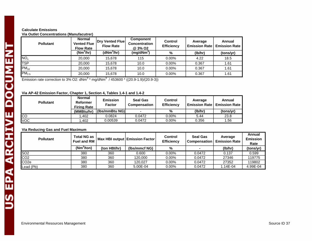
Environmental Resources Management Source ID 37
Calculate EmissionsVia Outlet Concentrations (Manufacutrer)
PollutantNormal
Vented Flue Flow Rate
Dry Vented Flue Flow Rate
Component Concentration
@ 3% O2
Control Efficiency
Average Emission Rate
Annual Emission Rate
(Nm3/hr) (dNm3/hr) (mg/dNm3) % (lb/hr) (tons/yr)NOx 20,000 15,678 115 0.00% 4.22 18.5TSP 20,000 15,678 10.0 0.00% 0.367 1.61PM10 20,000 15,678 10.0 0.00% 0.367 1.61PM2.5 20,000 15,678 10.0 0.00% 0.367 1.61Emission rate correction to 3% O2: dNm3 * mg/dNm3 / 453600 * ((20.9-1.9)/(20.9-3))
Via AP-42 Emission Factor, Chapter 1, Section 4, Tables 1.4-1 and 1.4-2
PollutantNormal
Reformer Firing Rate
Emission Factor
Seal Gas Compensation
Control Efficiency
Average Emission Rate
Annual Emission Rate
(MMBtu/hr) (lbs/mmBtu NG) - % (lb/hr) (tons/yr)CO 1,402 0.0824 0.0472 0.00% 5.44 23.8VOC 1,402 0.00539 0.0472 0.00% 0.356 1.56
Via Reducing Gas and Fuel Maximum
Pollutant Total NG as Fuel and RM Max HBI output Emission Factor Control
EfficiencySeal Gas
CompensationAverage
Emission Rate
Annual Emission
Rate(Nm3/ton) (ton HBI/hr) (lbs/mmcf NG) % - (lb/hr) (tons/yr)
SO2 380 360 0.600 0.00% 0.0472 0.137 0.599CO2 380 360 120,000 0.00% 0.0472 27346 119775CO2e 380 360 120,027 0.00% 0.0472 27352 119802Lead (Pb) 380 360 5.00E-04 0.00% 0.0472 1.14E-04 4.99E-04

Environmental Resources Management Source ID 37
Calculate HAP Emissions
PollutantNormal
Reformer Firing Rate
AP-42 Emission Factor
Nominal Natural Gas Supplement
Rate
Seal Gas System
Compensation
Average Emission Rate
Annual Emission Rate
(MMBtu/hr) (lb/MBtu) % (-) (lb/hr) (tons/yr)Benzene 1,402 2.06E-06 12.0% 0.0472 1.63E-05 7.15E-05Dichlorobenzene 1,402 1.18E-06 12.0% 0.0472 9.32E-06 4.08E-05Formaldehyde 1,402 7.35E-05 12.0% 0.0472 5.83E-04 2.55E-03n-Hexane 1,402 1.76E-03 12.0% 0.0472 1.40E-02 6.13E-02Naphthalene 1,402 5.98E-07 12.0% 0.0472 4.74E-06 2.08E-05Toluene 1,402 3.33E-06 12.0% 0.0472 2.64E-05 1.16E-04PAH 1,402 8.24E-08 12.0% 0.0472 6.53E-07 2.86E-06Arsenic 1,402 1.96E-07 12.0% 0.0472 1.55E-06 6.81E-06Barium 1,402 4.31E-06 12.0% 0.0472 3.42E-05 1.50E-04Beryllium 1,402 1.18E-08 12.0% 0.0472 9.32E-08 4.08E-07Cadmium 1,402 1.08E-06 12.0% 0.0472 8.55E-06 3.74E-05Chromium 1,402 1.37E-06 12.0% 0.0472 1.09E-05 4.76E-05Cobalt 1,402 8.24E-08 12.0% 0.0472 6.53E-07 2.86E-06Copper 1,402 8.33E-07 12.0% 0.0472 6.60E-06 2.89E-05Manganese 1,402 3.73E-07 12.0% 0.0472 2.95E-06 1.29E-05Mercury 1,402 2.55E-07 12.0% 0.0472 2.02E-06 8.85E-06Molybdenum 1,402 1.08E-06 12.0% 0.0472 8.55E-06 3.74E-05Nickel 1,402 2.06E-06 12.0% 0.0472 1.63E-05 7.15E-05Selenium 1,402 2.35E-08 12.0% 0.0472 1.86E-07 8.17E-07Vanadium 1,402 2.25E-06 12.0% 0.0472 1.79E-05 7.83E-05Zinc 1,402 2.84E-05 12.0% 0.0472 2.25E-04 9.87E-04

Environmental Resources Management Source ID 8
Emission Point Source Calculations
Emission Point Identifier: 8Description: Furnace Dedusting (BSG Dust Collection)
InputsDescription Value UnitsAnnual Hours of Operation 8,760 hr/yrIron Oxide Consumption Rate 2,205,000 tons/yrDesign Volmetric Vent Rate 63,000 Nm3/hrClean Gas Concentration 18.0 mg/Nm3
PM10 Mass Fraction 100% %PM2.5 Mass Fraction (Process Experience) 90.0% %
Emissions Summary
PollutantAverage
Emission Rate(lb/hr)
Annual Emission
Rate(tpy)
TSP 2.50 11.0PM10 2.50 11.0PM2.5 2.25 9.86
Calculate Emissions
Pollutant
Normal Dedusting
Airflow Rate
Maximum Clean Gas
Concentration
Mass Fraction of Total PM
Average Emission
Rate
Annual Emission
Rate
(Nm3/hr) (mg/Nm3) % (lb/hr) (tons/yr)TSP 63,000 18 100% 2.50 11.0PM10 63,000 18 100% 2.50 11.0PM2.5 63,000 18 90.0% 2.25 9.86

Environmental Resources Management Source ID 9
Emission Point Source Calculations
Emission Point Identifier: 9Description: Briquetter Dedusting
InputsDescription Value UnitsAnnual Hours of Operation 8,760 hr/yrDesigned Production Rate 2,205,000 tons/yrDesign Volmetric Vent Rate 100,000 Nm3/hrClean Gas Concentration 18.0 mg/Nm3
PM10 Mass Fraction 100% %PM2.5 Mass Fraction 90.0% %
Emissions Summary
PollutantAverage
Emission Rate(lb/hr)
Annual Emission
Rate(tpy)
TSP 3.97 17.4PM10 3.97 17.4PM2.5 3.57 15.6
Calculate Emissions
PollutantNormal
Dedusting Airflow Rate
Maximum Clean Gas
Concentration
Mass Fraction of Total PM
Average Emission
Rate
Annual Emission
Rate
(Nm3/hr) (mg/Nm3) % (lb/hr) (tons/yr)TSP 100,000 18.0 100% 3.97 17.4PM10 100,000 18.0 100% 3.97 17.4PM2.5 100,000 18.0 90.0% 3.57 15.6

Environmental Resources Management Source ID 12
Emission Point Source Calculations
Emission Point Identifier: 12Description: Transfer & Product Screening Station No. 1 (Pre Pile)
InputsDescription Value UnitsAnnual Hours of Operation 8,760 hr/yrDesigned Production Rate 2,205,000 tons/yrDesign Volmetric Vent Rate 40,000 Nm3/hrCleaned Gas Particulate Concentration 4.57 mg/Nm3
PM10 Mass Fraction 100.0% %PM2.5 Mass Fraction 90.0% %
Emissions Summary
PollutantAverage
Emission Rate(lb/hr)
Annual Emission
Rate(tpy)
TSP 0.40 1.77PM10 0.40 1.77PM2.5 0.36 1.59
Notes:Transfer & Product Screening Station No. 1 (Pre Pile)
Basis:The Screening Scrubber captures particulate emissions from the screening operations. This includes two transfer operations.

Environmental Resources Management Source ID 12
Calculations:
Calculate Emissions
Pollutant
Normal Dedusting
Airflow Rate
Clean Gas Concentration
Mass Fraction of Total PM
Average Emission
Rate
Annual Emission
Rate
(Nm3/hr) (mg/Nm3) % (lb/hr) (tons/yr)TSP 40,000 4.6 100% 0.40 1.77PM10 40,000 4.6 100% 0.40 1.77PM2.5 40,000 4.6 90% 0.36 1.59

Environmental Resources Management Source ID 14
Emission Point Source Calculations
Case: 14Description: Product Storage Piles
Inputs Value UnitsMaterial storage time 8,760 hrsStorage duration 365 daysAverage wind speed 12.0 mphNumber of dry days per year 288 daysPercentage of time wind speed > 12 mph 50% % (actual)Annual Material Throughput 2,205,000 tons/yrExcess Receiving Capacity (Annual) 110% %Conveyor System Service Factor (Hourly) 115% %Transfer rate-stacker 1,500 tons/hrTransfer rate-reclaimer 1,500 tons/hrWind Erosion Chemical Suppression 95% %Control efficiency -stacker 90% %Control efficiency -reclaimer 75% %Material moisture content 3.2 %Material silt content 4.3 %Storage area ground surface silt content 6.0 %Percentage PM 10 in material 13.0% %Pile maintenance/traffic hours 365 daysDozer miles per day 2 miDozer average weight 20 tonsFront end loader miles per day 10 miFront end loader average weight 20 tonsControl efficiency - maintenance/traffic 70% %Corpus Christi average wind speed (previous 60 years) http://www.ncdc.noaa.gov/oa/climate/online/ccd/avgwind.html, 7/27/12Corpus Christi mean number of days with precipitation .01" or more (previous 63 years) http://lwf.ncdc.noaa.gov/oa/climate/online/ccd/prcpdays.html, 7/27/12

Environmental Resources Management Source ID 14
Emissions Summary
Total Suspended Particles (TSP) Source Description Average
Emission RateAnnual Emission
Rate
(lbs/hr) (tpy)Material Transfers In/Out of Storage 0.26 1.12Equipment Traffic in Storage Area 1.17 5.12Wind Erosion 0.06 0.26
TOTAL 1.48 6.50
Total Particulate Matter < 10 um (PM10)
Source Description Average Emission Rate
Annual Emission Rate
(lbs/hr) (tpy)Material Transfers In/Out of Storage 0.12 0.51Equipment Traffic in Storage Area 0.31 1.36Wind Erosion 0.01 0.03
TOTAL 0.44 1.91
Total Particulate Matter < 2.5 um (PM2.5)
Source Description Average Emission Rate
Annual Emission Rate
(lbs/hr) (tpy)Material Transfers In/Out of Storage 0.04 0.16Equipment Traffic in Storage Area 0.03 0.14Wind Erosion 0.00 0.01
TOTAL 0.07 0.30
1Per AP-42 (Table 13.2.2-2), PM-30 is assumed equivalent to toal suspended particle matter (TSP)

Environmental Resources Management Source ID 14
Material Stacking and Reclaiming
Calculation Basis:
Calculation methodology derived from Table 12.5-4 "Pile Formation, Staacker, Pellet Ore, " AP-42 (10/86).Transfer Locations: (1) stacker/dump to pile; (2) reclaimer/loader out of pile onto conveyor.
Emission Calculations
Average Annual Particulate (TSP) Emissions from Material Storage Pile Transfers
Transfer Location Annual Throughput Emission Factor Number of Drops Uncontrolled Emissions
Overall Control Efficiency Controlled Emission Rates
(tons/yr1) (lb/ton) (lb/yr) % (lb/hravg) (tpy)Storage Pile (stacker) 2,425,743 0.0024 1.0 5,822 90.00% 0.07 0.29Storage Pile (reclaimer) 2,425,743 0.0024 1.0 5,822 75.00% 0.17 0.73TOTAL 0.23 1.02
Average Annual Particulate (PM10) Emissions from Material Storage Pile Transfers
Transfer Location Annual Throughput Emission Factor Number of Drops Uncontrolled Emissions
Overall Control Efficiency Controlled Emission Rates
(tons/yr1) (lb/ton) (lb/yr) % (lb/hravg) (tpy)Storage Pile (stacker) 2,425,743 0.0011 1.0 2,668 90.00% 0.03 0.13Storage Pile (reclaimer) 2,425,743 0.0011 1.0 2,668 75.00% 0.08 0.33TOTAL 0.11 0.47
Average Annual Particulate (PM2.5) Emissions from Material Storage Pile Transfers
Transfer Location Annual Throughput Emission Factor Number of Drops Uncontrolled Emissions
Overall Control Efficiency Controlled Emission Rates
(tons/yr1) (lb/ton) (lb/yr) % (lb/hravg) (tpy)Storage Pile (stacker) 2,425,743 0.00034 1.0 825 90.00% 0.01 0.04Storage Pile (reclaimer) 2,425,743 0.00034 1.0 825 75.00% 0.02 0.10TOTAL 0.03 0.14
1 capacity converted to US tons

Environmental Resources Management Source ID 14
Equipment Traffic in Storage Areas
Calculation Basis:
Calculation methodology derived from Section 13.2.2, "Unpaved Roads, " dated AP-42 (11/06) (in accordance with guidance from Section 13.2.4)Accounts for bulldozer (on pile) and front-end loader (between piles)
Emission factor (lb/VMT) = k(s/12) a (W/3) b
where: s = silt content of aggregate (%)1 Empirical Constants for Industrial RoadsW = mean vehicle weight 2 PM-2.5 PM-10 PM-30k,a, b = empirical constants for industrial roads 3 k 0.15 1.5 4.9
a 0.9 0.9 0.70b 0.45 0.45 0.45
Note: 1. From AP42, Section 13.2.2, Table 13.2.2-1, Dated 11/062. From AP42, Section 13.2.2, Table 13.2.2-3, Dated 11/063. From AP42, Section 13.2.2, Table 13.2.2-2, Dated 11/06
Calculation of Average Annual Controlled Emission Rate
Average Annual Controlled Emission Rate (tons/yr) = Vehicle Miles traveled in an day (VMT/day) * EF (lb PM / VMT ) * (number of days per year)*(1-control efficiency) / (2000 lb/ton)
Average Controlled Emission Rate (lb/hr) = Average Controlled Emission Rate (tons/yr)* (2000 lb/ton)/8760 hrs/yr

Environmental Resources Management Source ID 14
Emission Calculations:
Average Annual Particulate Emissions (TSP) from Equipment Traffic in Storage Areas
Vehicle Type Vehicle Miles Traveled Emission Factor Uncontrolled
Emission RateOverall Control
Efficiency Controlled Emission Rates
(VMT/day) (lb/VMT) (lb/day) % (lb/hravg) (tpy)Dozers 2 7.08 14.2 70.00% 0.18 0.78Front-end loaders 10 7.08 70.8 70.00% 0.89 3.88TOTAL 1.06 4.65
Average Annual Particulate Emissions (PM10) from Equipment Traffic in Storage Areas
Vehicle Type Vehicle Miles Traveled Emission Factor Uncontrolled
Emission RateOverall Control
Efficiency Controlled Emission Rates
(VMT/day) (lb/VMT) (lb/day) % (lb/hravg) (tpy)Dozers 2 1.89 3.8 70.00% 0.05 0.21Front-end loaders 10 1.89 18.9 70.00% 0.24 1.03TOTAL 0.28 1.24
Average Annual Particulate Emissions (PM2.5) from Equipment Traffic in Storage Areas
Vehicle Type Vehicle Miles Traveled Emission Factor Uncontrolled
Emission RateOverall Control
Efficiency Controlled Emission Rates
(VMT/day) (lb/VMT) (lb/day) % (lb/hravg) (tpy)Dozers 2 0.189 0.4 70.00% 0.00 0.02Front-end loaders 10 0.189 1.9 70.00% 0.02 0.10TOTAL 0.03 0.12

Environmental Resources Management Source ID 14
Wind Erosion
Calculation Basis:
Calculation methodology derived from EPA documents: "Fugitive Emissions from Integrated Iron and Steel Plants ", Section 2.2.4, Figure 3-9 (March 1978) and "Iron and Steel Plant Open Source Fugitive Emission Evaluation ", Section 2.1.3 and Table 2-1, Equation (8) (August 1978)Climatological data from New Orleans Regional Airport Weather Station (Jan-Dec 2007)
Emission factor (lb/ton) = 0.05(s/1.5)(D/90)(d/235)(f/15)
where: s = silt content of aggregate (%)1
D = duration of storage (days)d = dry days per year2
f = percentage of time wind speed exceeds 12 mph
Note: 1. From AP42, Section 13.2.2, Table 13.2.2-1, Dated 11/062. From AP42, Section 13.2.2, Table 13.2.2-1, Dated 11/06
Calculation of Average Annual Controlled Emission Rate
Average Annual Controlled Emission Rate (tons/yr) = tons of aggregate through storage cycle (tons) * EF (lb PM / VMT ) * (1 - Control efficiency)Average Controlled Emission Rate (lb/hr) = Average Controlled Emission Rate (tons/yr)* (2000 lb/ton)/8760 hrs/yr

Environmental Resources Management Source ID 14
Emission Calculations:
Average Annual Particulate Emissions (TSP) from Wind Erosion from Storage Piles
Aggregate Throughput1 Emission Factor Uncontrolled Emissions Rate
Overall Control Efficiency Controlled Average Emission Rate
(tons/yr) (lb/ton) (lb/yr) % (lb/hravg) (tpy)Iron Ore Pellets 404,290 0.02 9,601 95.00% 0.05 0.24
Average Annual Particulate Emissions (PM10) from Wind Erosion from Storage PilesAggregate TSP Controlled Avg. Emission Rate % PM 10 Controlled Average Emission Rate
(lb/hravg) (tpy) % (lb/hravg) (tpy)Iron Ore Pellets 0.05 0.24 13.00% 0.01 0.03
Average Annual Particulate Emissions (PM2.5) from Wind Erosion from Storage PilesAggregate TSP Controlled Avg. Emission Rate % PM2.5
2 Controlled Average Emission Rate(lb/hravg) (tpy) % (lb/hravg) (tpy)
Iron Ore Pellets 0.05 0.24 1.95% 0.00 0.00
1 Assume 2-month supply onsite at all times2 Per an EPA document showing that PM2.5/PM10 for metallic ore and coal piles is 0.15- www.epa.gov/ttn/chief/conference/ei15/session14/cowherd.pdf

Environmental Resources Management Source ID 13
Emission Point Source Calculations
Emission Point Identifier: 13Description: Transfer & Product Screening Station No. 2 (Post Pile)
InputsDescription Value UnitsAnnual Hours of Operation 8,760 hr/yrDesigned Production Rate 2,205,000 tons/yr same as iron oxide consumption rate?Design Volmetric Vent Rate 40,000 Nm3/hrCleaned Gas Particulate Concentration 4.57 mg/Nm3
PM10 Mass Fraction 100.0% %PM2.5 Mass Fraction 90.0% %
Emissions Summary
PollutantAverage
Emission Rate(lb/hr)
Annual Emission
Rate(tpy)
TSP 0.40 1.77PM10 0.40 1.77PM2.5 0.36 1.59
Notes:Transfer & Product Screening Station No. 2 (Post Pile)
Basis:The Screening Scrubber captures particulate emissions from the screening operations. This includes two transfer operations.

Environmental Resources Management Source ID 13
Calculations:
Calculate Emissions
Pollutant
Normal Dedusting
Airflow Rate
Nominal Clean Gas
Concentration
Mass Fraction of Total PM
Average Emission
Rate
Annual Emission
Rate
(Nm3/hr) (mg/Nm3) % (lb/hr) (tons/yr)TSP 40,000 4.57 100% 0.40 1.77PM10 40,000 4.57 100% 0.40 1.77PM2.5 40,000 4.57 90% 0.36 1.59

Environmental Resources Management Source ID 36
Emission Point Source Calculations
Case: 36Description: Remet / Fines Storage
Inputs Value UnitsMaterial storage time 8,760 hrsStorage duration 365 daysAverage wind speed 12.0 mphNumber of dry days per year 288 daysPercentage of time wind speed > 12 mph 50% % (actual)Annual Material Throughput1 130,000 tons/yrExcess Receiving Capacity (Annual) 110% %Conveyor System Service Factor (Hourly) 100% %Transfer rate-stacker 50 tons/hrTransfer rate-reclaimer 50 tons/hrWind Erosion Chemical Suppression 95% %Control efficiency -stacker 90% %Control efficiency -reclaimer 75% %Material moisture content 3.2 %Material silt content 4.3 %Storage area ground surface silt content 6.0 %Percentage PM 10 in material, estimate as screened material 20.0% %Pile maintenance/traffic hours 365 daysDozer miles per day 0.5 miDozer average weight 20 tonsFront end loader miles per day 1 miFront end loader average weight 20 tonsControl efficiency - maintenance/traffic 70% %http://www.ncdc.noaa.gov/oa/climate/online/ccd/avgwind.htmlCorpus Christi mean number of days with precipitation .01" or more (previous 63 years) http://lwf.ncdc.noaa.gov/oa/climate/online/ccd/prcpdays.html, 7/27/12http://www.ncdc.noaa.gov/oa/climate/online/ccd/avgwind.htmlEstimated maximum reject of ore or product combined
1 Across multiple remet and storage piles and bunkers, facility annual total
Emissions Summary
Total Suspended Particles (TSP) Source Description Average
Emission RateAnnual Emission
Rate
(lbs/hr) (tpy)Material Transfers In/Out of Storage 0.00 0.02Equipment Traffic in Storage Area 0.15 0.64Wind Erosion 0.02 0.08
TOTAL 0.17 0.74

Environmental Resources Management Source ID 36
Total Particulate Matter < 10 um (PM10)
Source Description Average Emission Rate
Annual Emission Rate
(lbs/hr) (tpy)Material Transfers In/Out of Storage 0.00 0.01Equipment Traffic in Storage Area 0.04 0.17Wind Erosion 0.00 0.02
TOTAL 0.04 0.20
Total Particulate Matter < 2.5 um (PM2.5)
Source Description Average Emission Rate
Annual Emission Rate
(lbs/hr) (tpy)Material Transfers In/Out of Storage 0.001 0.00Equipment Traffic in Storage Area 0.004 0.02Wind Erosion 0.001 0.00
TOTAL 0.005 0.02
1Per AP-42 (Table 13.2.2-2), PM-30 is assumed equivalent to toal suspended particle matter (TSP)
Material Transfers In/Out of Storage
Calculation Basis:
Calculation methodology derived from Table 12.5-4 "Pile Formation, Stacker, Pellet Ore, " AP-42 (10/86).Transfer Locations: (1) stacker/dump to pile; (2) reclaimer/loader out of pile onto conveyor; (3) equipment traffic within pile area.
Emission Calculations
Average Annual Particulate (TSP) Emissions from Material Storage Pile Transfers
Transfer Location Annual Throughput Emission Factor Number of
DropsUncontrolled
EmissionsOverall Control
Efficiency Controlled Emission Rates
(tons/yr1) (lb/ton) (lb/yr) % (lb/hravg) (tpy)Storage Pile (drop point) 143,014 0.0024 1.0 343 90.00% 0.004 0.017TOTAL 0.004 0.017

Environmental Resources Management Source ID 36
Average Annual Particulate (PM10) Emissions from Material Storage Pile Transfers
Transfer Location Annual Throughput Emission Factor Number of
DropsUncontrolled
EmissionsOverall Control
Efficiency Controlled Emission Rates
(tons/yr1) (lb/ton) (lb/yr) % (lb/hravg) (tpy)Storage Pile (drop point) 143,014 0.0011 1.0 157 90.00% 0.002 0.008TOTAL 0.002 0.008
Average Annual Particulate (PM2.5) Emissions from Material Storage Pile Transfers
Transfer Location Annual Throughput Emission Factor Number of
DropsUncontrolled
EmissionsOverall Control
Efficiency Controlled Emission Rates
(tons/yr1) (lb/ton) (lb/yr) % (lb/hravg) (tpy)Storage Pile (drop point) 143,014 0.00034 1.0 49 90.00% 0.001 0.002TOTAL 0.001 0.002
1 capacity converted to US tons
Equipment Traffic in Storage Areas
Calculation Basis:
Calculation methodology derived from Section 13.2.2, "Unpaved Roads, " dated AP-42 (11/06) (in accordance with guidance from Section 13.2.4)Accounts for bulldozer (on pile) and front-end loader (between piles)
Emission factor (lb/VMT) = k(s/12) a (W/3) b
where: s = silt content of aggregate (%)1 Empirical Constants for Industrial RoadsW = mean vehicle weight 2 PM-2.5 PM-10 PM-30k,a, b = empirical constants for industrial roads 3 k 0.15 1.5 4.9
a 0.9 0.9 0.70b 0.45 0.45 0.45
Note: 1. From AP42, Section 13.2.2, Table 13.2.2-1, Dated 11/062. From AP42, Section 13.2.2, Table 13.2.2-3, Dated 11/063. From AP42, Section 13.2.2, Table 13.2.2-2, Dated 11/06
Calculation of Average Annual Controlled Emission Rate
Average Annual Controlled Emission Rate (tons/yr) = Vehicle Miles traveled in an day (VMT/day) * EF (lb PM / VMT ) * (number of days per year)*(1-control efficiency) / (2000 lb/ton)
Average Controlled Emission Rate (lb/hr) = Average Controlled Emission Rate (tons/yr)* (2000 lb/ton)/8760 hrs/yr

Environmental Resources Management Source ID 36
Emission Calculations:
Average Annual Particulate Emissions (TSP) from Equipment Traffic in Storage Areas
Vehicle Type Vehicle Miles Traveled Emission Factor Uncontrolled
Emission RateOverall Control
Efficiency Controlled Emission Rates
(VMT/day) (lb/VMT) (lb/day) % (lb/hravg) (tpy)Dozers 1 7.08 3.5 70.0% 0.044 0.19Front-end loaders 1 7.08 7.1 70.0% 0.089 0.39TOTAL 0.13 0.58
Average Annual Particulate Emissions (PM10) from Equipment Traffic in Storage Areas
Vehicle Type Vehicle Miles Traveled Emission Factor Uncontrolled
Emission RateOverall Control
Efficiency Controlled Emission Rates
(VMT/day) (lb/VMT) (lb/day) % (lb/hravg) (tpy)Dozers 1 1.89 0.9 70.0% 0.012 0.05Front-end loaders 1 1.89 1.9 70.0% 0.024 0.10TOTAL 0.035 0.16
Average Annual Particulate Emissions (PM2.5) from Equipment Traffic in Storage Areas
Vehicle Type Vehicle Miles Traveled Emission Factor Uncontrolled
Emission RateOverall Control
Efficiency Controlled Emission Rates
(VMT/day) (lb/VMT) (lb/day) % (lb/hravg) (tpy)Dozers 1 0.189 0.1 70.0% 0.0012 0.005Front-end loaders 1 0.189 0.2 70.0% 0.0024 0.010TOTAL 0.0035 0.016
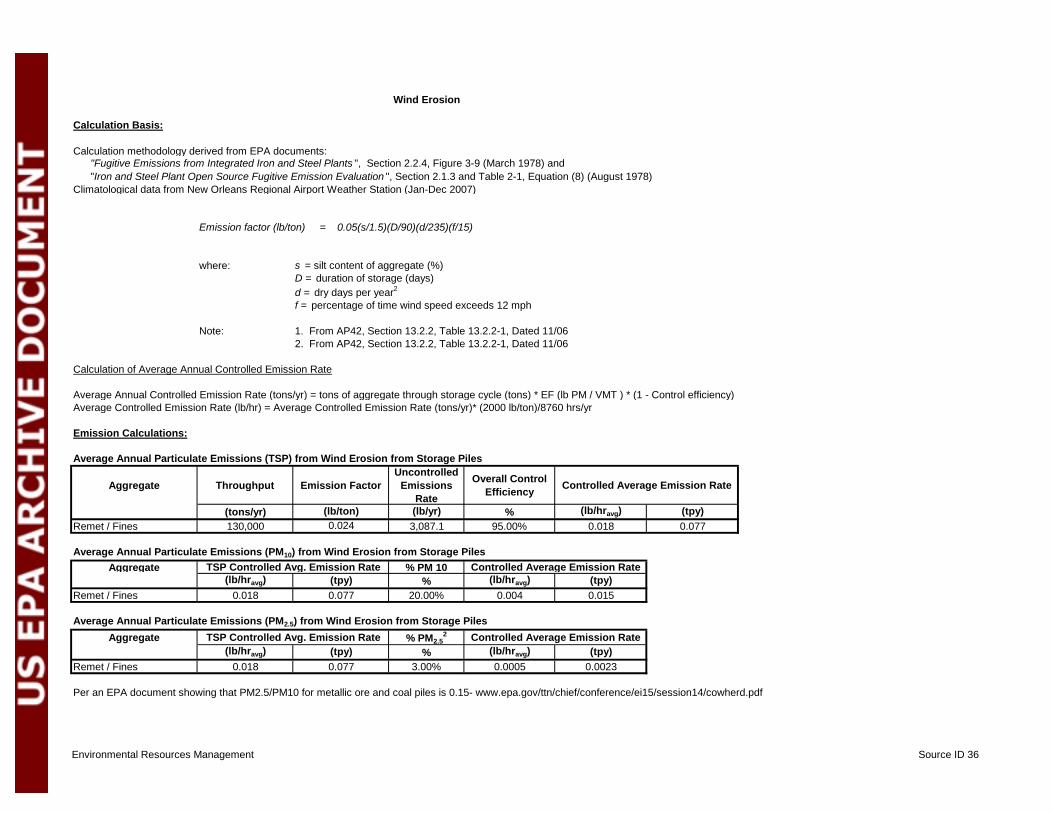
Environmental Resources Management Source ID 36
Wind Erosion
Calculation Basis:
Calculation methodology derived from EPA documents: "Fugitive Emissions from Integrated Iron and Steel Plants ", Section 2.2.4, Figure 3-9 (March 1978) and "Iron and Steel Plant Open Source Fugitive Emission Evaluation ", Section 2.1.3 and Table 2-1, Equation (8) (August 1978)Climatological data from New Orleans Regional Airport Weather Station (Jan-Dec 2007)
Emission factor (lb/ton) = 0.05(s/1.5)(D/90)(d/235)(f/15)
where: s = silt content of aggregate (%)D = duration of storage (days)d = dry days per year2
f = percentage of time wind speed exceeds 12 mph
Note: 1. From AP42, Section 13.2.2, Table 13.2.2-1, Dated 11/062. From AP42, Section 13.2.2, Table 13.2.2-1, Dated 11/06
Calculation of Average Annual Controlled Emission Rate
Average Annual Controlled Emission Rate (tons/yr) = tons of aggregate through storage cycle (tons) * EF (lb PM / VMT ) * (1 - Control efficiency)Average Controlled Emission Rate (lb/hr) = Average Controlled Emission Rate (tons/yr)* (2000 lb/ton)/8760 hrs/yr
Emission Calculations:
Average Annual Particulate Emissions (TSP) from Wind Erosion from Storage Piles
Aggregate Throughput Emission Factor Uncontrolled
Emissions Rate
Overall Control Efficiency Controlled Average Emission Rate
(tons/yr) (lb/ton) (lb/yr) % (lb/hravg) (tpy)Remet / Fines 130,000 0.024 3,087.1 95.00% 0.018 0.077
Average Annual Particulate Emissions (PM10) from Wind Erosion from Storage PilesAggregate TSP Controlled Avg. Emission Rate % PM 10 Controlled Average Emission Rate
(lb/hravg) (tpy) % (lb/hravg) (tpy)Remet / Fines 0.018 0.077 20.00% 0.004 0.015
Average Annual Particulate Emissions (PM2.5) from Wind Erosion from Storage PilesAggregate TSP Controlled Avg. Emission Rate % PM2.5
2 Controlled Average Emission Rate(lb/hravg) (tpy) % (lb/hravg) (tpy)
Remet / Fines 0.018 0.077 3.00% 0.0005 0.0023
Per an EPA document showing that PM2.5/PM10 for metallic ore and coal piles is 0.15- www.epa.gov/ttn/chief/conference/ei15/session14/cowherd.pdf

Environmental Resources Management Source ID 33
Emission Point Source Calculations
Case: 33Description: Cooling Tower
Inputs ValueAnnual operating hours 8,760Cooling tower circulating water rate 20,000Percent drift 0.0005%Total Dissolved Solids Content 35,000Percent of Total PM that is PM10
1 3.0% %
1 Based upon document "Calculating PM10 Emissions from Cooling Towers" by Joel Reisman and Gordon Frisbie (Abstract No. 316, Session No. AM-1b)
Emissions Summary
Pollutant Average Emission Rate
Annual Emission
Rate(lbs/hr) (tpy)
TSP 2.61 11.44PM10 0.08 0.34PM2.5 0.08 0.34
1 Assume TSP=PM10=PM2.5
ppm
Unitshrs
gal/min%

Environmental Resources Management Source ID 33
Calculation Basis:
Calculation methodology based upon a conservative mass balance approach.
Calculation of Average Annual Emission Rates
Emission Rate (lb/hravg) = Drift rate (gal/min)*TDS content (ppm)/1,000,000*60min/hr*0.13368 ft3/gallon *62 lb/ft3*1.5 Cycles
Emission Rate (tpy) = Average Controlled Emission Rate (lb/hravg) * annual operating hours (hrs/yr) / (2000 lb/ton)
Emission Calculations
PollutantCooling Tower
Circulating Water Rate
% Drift Drift Rate
Total Dissolved
Solids Content
Average Emission
Rate
Annual Emission
Rate
(gal/min) % (gal/min) (ppm) (lb/hravg) (tpy)TSP 20,000 0.0005% 0.10 35,000 2.61 11.44PM10 20,000 0.0005% 0.10 35,000 0.08 0.34PM2.5
1 20,000 0.0005% 0.10 35,000 0.08 0.34
1 Assuming PM10 = PM2.5

Environmental Resources Management Source ID 39
Emission Point Source Calculations
Case: 39Description: Paved Road Fugitive Dust
Value UnitsDays of Operation per year 365 days/yrAverage road surface silt loading 9.7 %Fleet Average Weight 10.50 tonsVehicle Miles Travelled - Heavy Duty 50 miles/dayNumber of Days with > 0.01 inches of rain 77 days/yrControl efficiency - Sweeping 90% %Corpus Christi mean number of days with precipitation .01" or more http://lwf.ncdc.noaa.gov/oa/climate/online/ccd/prcpdays.html, 7/27/12
Emissions Summary
Source Description Pollutant Average Emission
Rate
Annual Emission
Rate(lbs/hr) (tpy)
TSP1 0.25 1.08PM10 0.05 0.21PM2.5 0.01 0.03
1 Per AP-42 (Table 13.2.2-2), PM-30 is assumed equivalent to total suspended particle matter (TSP)
Inputs
Paved Road Fugitive Emissions

Environmental Resources Management Source ID 39
Calculation Basis:
Calculation methodology derived from Section 13.2.1, "Paved Roads, " dated AP-42 (11/06)Accounts for fall vehicular traffic on paved roads (assumes 1 mile ot paved road at facility)
where: sL = road surface silt loading, g/m2 1
W = average vehicle weight, tons 2
k = particle size multiplier, lb/VMT 3
C - emission factor for 1980's vehicle fleet exhaust, brake wear, and tire wear, lb/VMT 4
Note: 1. From AP42, Section 13.2.1, Table 13.2.1-4, Dated 11/062. From AP42, Section 13.2.2, Table 13.2.2-3, Dated 11/063. From AP42, Section 13.2.1, Table 13.2.1-1, Dated 11/064. From AP42, Section 13.2.1, Table 13.2.1-2, Dated 11/07
Particle Size Range k C0.082 0.000470.02 0.00047
0.016 0.000470.0024 0.00036
Emission factor extrapolated for natural mitigation (lb/VMT) E ext = E [1 - (P/365)]
where: E = Uncontrolled emission factorP = Number of days with > 0.01 inches of precipitation
< 2.5 micrometers
< 30 micrometers< 15 micrometers< 10 micrometers
CWsLktraveledmilevehiclelbfactorEmission −
=
5.165.0
3*
2*)/(

Environmental Resources Management Source ID 39
Emission Calculations:
Calculation of Average Annual Controlled Emission Rate
Average Annual Controlled Emission Rate (tons/yr) = Vehicle Miles travelled in an day (VMT/day) * EF (lb PM / VMT ) * (number of days per year)*(1-control effciency) / (2000 lb/ton)
Average Controlled Emission Rate (lb/hr) = Average Controlled Emission Rate (tons/yr)* (2000 lb/ton)/8760 hrs/yr
Average Annual Particulate Emissions (TSP) from Vehicular Traffic on Paved Roads
Emission Point Vehicle Miles Travelled
Emission Factor
Uncontrolled Emission
Rate
Overall Control
EfficiencyControlled Emission Rate
(VMT/day) (lb/VMT) (lb/day) % (lb/hravg) (tpy)All Vehicular Traffic 50 1.182 59.1 90% 0.25 1.08TOTAL 0.25 1.08
Average Annual Particulate Emissions (PM10) from Vehicular Traffic on Paved Roads
Vehicle Type Vehicle Miles Travelled
Emission Factor
Uncontrolled Emission
Rate
Overall Control
EfficiencyControlled Emission Rate
(VMT/day) (lb/VMT) (lb/day) % (lb/hravg) (tpy)All Vehicular Traffic 50 0.230 11.5 90% 0.05 0.21TOTAL 0.05 0.21
Average Annual Particulate Emissions (PM2.5) from Vehicular Traffic on Paved Roads
Vehicle Type Vehicle Miles Travelled
Emission Factor
Uncontrolled Emission
Rate
Overall Control
EfficiencyControlled Emission Rate
(VMT/day) (lb/VMT) (lb/day) % (lb/hravg) (tpy)All Vehicular Traffic 50 0.034 1.7 90% 0.01 0.03TOTAL 0.01 0.03

Environmental Resources Management Source ID 34
Emission Point Source Calculations
Case: 34Description: Emergency Generator
Given:1) 2500kWe Diesel Emergency Power Generator2) Nominal Emissions data provided by a NSPS Certified manufacturer
Mechanical kWm 2500Load % 100
NOx g/kWh 5.822HC g/kWh 0.179CO g/kWh 0.689PM g/kWh 0.085
3) Fuel: 15ppm (0.0015%) Sulfur Diesel 4) SO2 emission factor: AP42 Chapter 3, Section 4: 8.09E-3*S = 8.09E-3*.0015 = 1.2E-5 lb/hph = 0.0077 g/kWh5) NSPS IIII Hours based on Readiness and Maintenance limit of 100 hours (emergency use not limited)
Nominal Emissions Calculation - Requested Limit
Pollutant
100% Load
(g/kWh)
100% Hourly
Per Unit(lbs/hr)
100%Annual
Emission Rate(tpy)
NOx 5.822 32.09 1.60HC 0.179 0.99 0.049CO 0.689 3.80 0.190PM 0.085 0.47 0.023SO2 0.0077 0.04 0.002
Hours Per Unit100% 100

Environmental Resources Management Source ID 35
Emission Point Source Calculations
Case: 35Description: Fire Pump
Given:1) 175kWe Diesel Emergency Power Generator2) Nominal Emissions data provided by a NSPS Certified manufacturer
Mechanical kWm 175Load % 100
NOx g/kWh 5.822HC g/kWh 0.179CO g/kWh 0.689PM g/kWh 0.085
3) Fuel: 15ppm (0.0015%) Sulfur Diesel 4) SO2 emission factor: AP42 Chapter 3, Section 4: 8.09E-3*S = 8.09E-3*.0015 = 1.2E-5 lb/hph = 0.0077 g/kWh5) NSPS IIII Hours based on Readiness and Maintenance limit of 100 hours (emergency use not limited)
Nominal Emissions Calculation - Requested Limit
Pollutant
100% Load
(g/kWh)
100% Hourly
Per Unit(lbs/hr)
100%Annual
Emission Rate(tpy)
NOx 5.822 2.25 0.112HC 0.179 0.07 0.003CO 0.689 0.27 0.013PM 0.085 0.03 0.002SO2 0.0077 0.00 1.49E-04
Hours Per Unit100% 100

Appendix B
Figures

FUTURE RAILROAD R-O-W
Corpus Christi Bay
DRI-PLANT 1
··
pow
er li
ne c
orrid
or
power line corridor
substation
CHENIERE
~27km
mph
29.10.2012
OverviewM 1:150 000
Wind directionIngleside Naval Station
General LayoutM 1:7500
Golf von Mexico
0 500m
Scale
EINEN SCHRITT VORAUS.
Konzeption Horizontale ErweiterungTechnical Investment
GO WEST
GENERAL LAYOUT:Texas/Corpus Christi - La QuintaDRI/HBI - Plant 1 (2,0 Mio.t/a) - MIDREX
31.08.2012 Durstberger 73546
LAY1
AKON-GOWE
1004251
1:7500

FUTURE RAILROAD R-O-W
DRI-PLANT 1
··
~27km
mph
OverviewM 1:150 000
General LayoutM 1:2500
Golf von Mexico
0 200m
Scale 1:2500
100m
EINEN SCHRITT VORAUS.
Konzeption Horizontale ErweiterungTechnical Investment
GO WEST
GENERAL LAYOUT:Texas/Corpus Christi - La QuintaDRI/HBI - Plant 1 (2,0 Mio.t/a) - MIDREX
31.08.2012 Durstberger 73546
LAY2
AKON-GOWE
1004251
1:2500
29.10.2012
Wind directionIngleside Naval Station

[
3000 Foot Radius
1 Mile Radius
CH
S 8
/3/1
2 N
AD
83 U
TM
Zo
ne
14
N
Environmental Resources
Management NC, Inc.
FIGURE 2-1
3000 FOOT AND 1 MILE RADII MAP
Voestalpine La Quinta Plant
Corpus Christi, Texas
[
[ Approximate center of La Quinta Plant ±0 2,000 4,0001,000
Feet

[
3000 Foot Radius
1 Mile Radius
CH
S 8
/3/1
2 N
AD
83 U
TM
Zo
ne
14
N
Environmental Resources
Management NC, Inc.
FIGURE 2-2
3000 FOOT AND 1 MILE RADII MAP
Voestalpine La Quinta Plant
Corpus Christi, Texas
[
[ Approximate center of La Quinta Plant ±0 2,000 4,0001,000
Feet

Oxide Transfer 1 : • hooded conveyors • enclosed transfer points
Oxide Pellet Pile • Stacker • Reclaimer
Oxide Transfer 2 : • hooded conveyors • enclosed transfer points
Oxide & Remet Screening • hooded conveyors • enclosed transfer points • screening equipment
Furnace Charge Hopper Loading Silos • hooded conveyors • enclosed transfer points
Ore to Figure 4
PM
Bag House
PM
Bag House
PM
Bag House
PM
Bag House
PM
Dock Ore Unloading / Product Loading Gantry Crane
PM
Bag House
PM
Ship . Oxidizes Pellets
enclosed conveyors, water spray at transfer points additionally, water sprays, wind shields, or partial enclosure if full enclosure not practical
surface treatment such wetting with water and/or chemical agents, vehicle restrictions, surface improvement for unpaved roads
enclosed conveyors, water spray at transfer points additionally, water sprays, wind shields, or partial enclosure if full enclosure not practical
Process Flow Diagram Ore Handling / Figure 3

Process Flow Diagram Reduction, Reformer, Hot Briquetting Figure 4

Product Storage Pile
Bag House
PM
HBI Product from Figure 4
Remet / Fines Storage
PM
Product Transfer/Screening 2 : • hooded conveyors • enclosed transfer points • screening Equipment
Bag House
PM
Dock Ore Unloading / Product Loading Gantry Crane
PM
Ship . HBI Product
enclosed conveyors, water spray at transfer points additionally, water sprays, wind shields, or partial enclosure if full enclosure not practical
PM
surface treatment such wetting with water and/or chemical agents, vehicle restrictions, surface improvement for unpaved roads
surface treatment such wetting with water and/or chemical agents, vehicle restrictions, surface improvement for unpaved roads
Product Transfer/Screening 1 : • hooded conveyors • enclosed transfer points • screening Equipment
Process Flow Diagram Product Handling Figure 5

Appendix C
GHG BACT Decisions
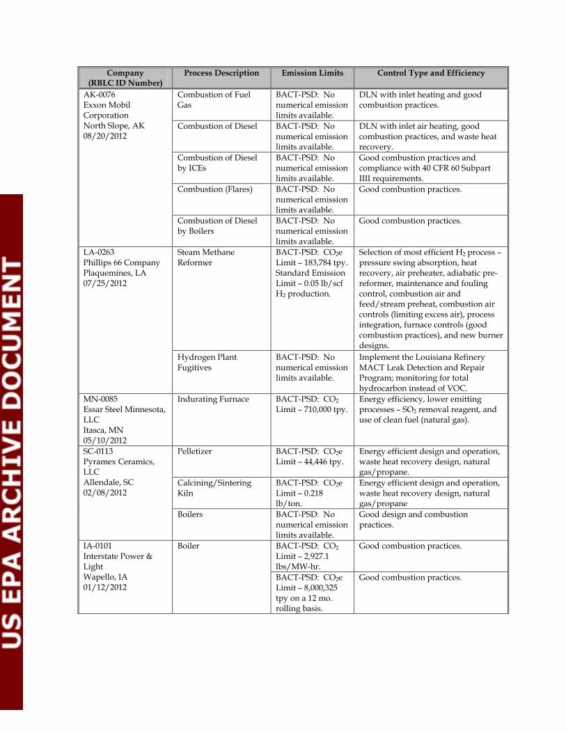
Company (RBLC ID Number)
Process Description Emission Limits Control Type and Efficiency
AK-0076 Exxon Mobil Corporation North Slope, AK 08/20/2012
Combustion of Fuel Gas
BACT-PSD: No numerical emission limits available.
DLN with inlet heating and good combustion practices.
Combustion of Diesel BACT-PSD: No numerical emission limits available.
DLN with inlet air heating, good combustion practices, and waste heat recovery.
Combustion of Diesel by ICEs
BACT-PSD: No numerical emission limits available.
Good combustion practices and compliance with 40 CFR 60 Subpart IIII requirements.
Combustion (Flares) BACT-PSD: No numerical emission limits available.
Good combustion practices.
Combustion of Diesel by Boilers
BACT-PSD: No numerical emission limits available.
Good combustion practices.
LA-0263 Phillips 66 Company Plaquemines, LA 07/25/2012
Steam Methane Reformer
BACT-PSD: CO2e Limit – 183,784 tpy. Standard Emission Limit – 0.05 lb/scf H2 production.
Selection of most efficient H2 process – pressure swing absorption, heat recovery, air preheater, adiabatic pre-reformer, maintenance and fouling control, combustion air and feed/stream preheat, combustion air controls (limiting excess air), process integration, furnace controls (good combustion practices), and new burner designs.
Hydrogen Plant Fugitives
BACT-PSD: No numerical emission limits available.
Implement the Louisiana Refinery MACT Leak Detection and Repair Program; monitoring for total hydrocarbon instead of VOC.
MN-0085 Essar Steel Minnesota, LLC Itasca, MN 05/10/2012
Indurating Furnace BACT-PSD: CO2 Limit – 710,000 tpy.
Energy efficiency, lower emitting processes – SO2 removal reagent, and use of clean fuel (natural gas).
SC-0113 Pyramex Ceramics, LLC Allendale, SC 02/08/2012
Pelletizer BACT-PSD: CO2e Limit – 44,446 tpy.
Energy efficient design and operation, waste heat recovery design, natural gas/propane.
Calcining/Sintering Kiln
BACT-PSD: CO2e Limit – 0.218 lb/ton.
Energy efficient design and operation, waste heat recovery design, natural gas/propane
Boilers BACT-PSD: No numerical emission limits available.
Good design and combustion practices.
IA-0101 Interstate Power & Light Wapello, IA 01/12/2012
Boiler BACT-PSD: CO2 Limit – 2,927.1 lbs/MW-hr.
Good combustion practices.
BACT-PSD: CO2e Limit – 8,000,325 tpy on a 12 mo. rolling basis.
Good combustion practices.

Company (RBLC ID Number)
Process Description Emission Limits Control Type and Efficiency
Universal Cement Chicago, IL 12/20/2011
Portland Cement Manufacturing Facility
BACT-PSD: CO2 Limit – 1,860 lbs CO2e/ton clinker on a 12-month rolling average basis, 0.93 tpy CO2e.
Multi-stage preheater/ precalciner kiln with selection of refractory and a kiln seal management program and a third generation reciprocating clinker cooler.
MN-0084 United States Steel Corp. Itasca, MN 12/06/2011
Grate Kiln – Down Draft Drying Zone
BACT-PSD: CO2 Limit – 114,000 tpy on a 12 mo. rolling basis.
Fuel efficiency via heat recovery from pellet coolers. Use of a primary fuel mix of 50% biomass and 50% natural gas.
BACT-PSD: CO2e Limit – 186,400 tpy on a 12 mo. rolling basis.
Fuel efficiency via heat recovery from pellet coolers. Use of a primary fuel mix of 50% biomass and 50% natural gas.
FL-0330 Port Dolphin Energy, LLC Hillsborough, FL 12/01/2011
Boilers BACT-PSD: CO2 Limit – 117 lbs/MMBtu on 8 hour rolling average.
Tuning, optimization, instrumentation and controls, insulation, and turbulent flow.
Power Generator Engines
BACT-PSD: CO2 Limit – 181 g/kw-hr on 8 hour rolling average (natural gas), 253 g/kw-hr on 8 hour rolling average (low sulfur fuel oil).
Use of efficient engine design and use of primarily natural gas.
Fugitive Emissions BACT-PSD: No numerical emission limits available.
A gas leak detection system will be used for CO2.
GA-0143 JM Huber Corp. Jackson, GA 11/10/2011
Wellons Furnace BACT-PSD: No numerical emission limits available.
The combustion of biomass and the use of good combustion/operating practices to control GHGs. *No control has been established to minimize N2O emissions based on adverse NOX impacts.
Dryer System BACT-PSD: No numerical emission limits available.
The combustion of biomass and the use of good combustion/operating practices to control GHGs. *No control has been established to minimize N2O emissions based on adverse NOX impacts.
IN-0135 Hoosier Energy Rec. Inc. – Merom Generating Station Sullivan, IN 11/10/2011
Coal Bed Methane-Fired Standby Flare w/ Propane Fired Pilot
Case-by-Case: CO2 Limit - 3,235 lbs/MW-hr, 4,852 tpy on a 12 mo. rolling basis.
Good combustion practices and proper maintenance.
Case-by-Case: CH4 Limit – 0.06 lbs/MW-hr, 0.08 tpy on a 12 mo. rolling basis.
Good combustion practices and proper maintenance.

Company (RBLC ID Number)
Process Description Emission Limits Control Type and Efficiency
Case-by-Case: N2O Limit – 0.05 lbs/MW-hr, 0.08 tpy on a 12 mo. rolling basis.
Good combustion practices and proper maintenance.
Coal Bed Methane CBM Dehydrator Units
Case-by-Case: CO2 Limit – 59.36 lbs/hr, 260 tpy.
Proper maintenance.
4-Stroke Lean Burn Coal Bed Methane – Fired RICE
Case-by-Case: CO2 Limit – 1,100 lbs/MW-hr on a 3 hour avg. basis, 16,030 tpy.
Good combustion practices and proper maintenance.
Case-by-Case: CH4 Limit – 9.57 lbs/MW-hr on a 3 hour avg. basis, 139.4 tpy.
Good combustion practices and proper maintenance.
Case-by-Case: N2O Limit – 0.23 lbs/MW-hr, 3.35 tpy.
Good combustion practices and proper maintenance.
FL-0328 ENI U.S. Operating Company, Inc. Lloyd Ridge (OCS), FL 10/27/2011 *Draft Determination
Main Propulsion Engines
BACT-PSD: CO2 Limit – 700 g/kw-hr on 24 hour rolling basis.
Use of good combustion practices based on the current manufacturer’s specifications, and additional enhanced work practice standards including an engine performance management system and the Diesel Engines with Turbochargers (DEWT) measurement system.
Crane Engines BACT-PSD: CO2 Limit – 722 tpy on a 12 mo. rolling basis.
Use of certified EPA Tier 1 engines and good combustion practices based on the current manufacturer’s specifications for this engine.
Crane Engines BACT-PSD: CO2 Limit – 687 tpy on a 12 mo. rolling basis.
Use of good combustion practices, based on the current manufacturer’s specifications for this engine.
Emergency Engine BACT-PSD: CO2 Limit – 14.6 tpy on a 12 mo. rolling basis.
Good combustion practices based on manufacturer’s specifications.
Emergency Fire Pump Engine
BACT-PSD: CO2 Limit – 2.4 tpy on a 12 mo. rolling basis.
Good combustion practices based on manufacturer’s specifications.
Boiler BACT-PSD: CO2 Limit – 565 tpy on a 12 mo. rolling basis.
Use of good combustion and maintenance practices, based on the current manufacturer’s specifications for this boiler.
LA-0254 Entergy Louisiana, LLC
Auxiliary Boiler BACT-PSD: CO2 Limit – 117 lbs/MMBtu.
Proper operation and good combustion practices.

Company (RBLC ID Number)
Process Description Emission Limits Control Type and Efficiency
Jefferson, LA 08/16/2011
BACT-PSD: CH4 Limit – 0.0022 lbs/MMBtu.
Proper operation and good combustion practices.
BACT-PSD: N2O Limit – 0.0002 lbs/MMBtu.
Proper operation and good combustion practices.
Emergency Diesel Generator
BACT-PSD: CO2 Limit – 163.0 lbs/MMBtu.
Proper operation and good combustion practices.
BACT-PSD: CH4 Limit – 0.0061 lbs/MMBtu.
Proper operation and good combustion practices.
BACT-PSD: N2O Limit – 0.0014 lbs/MMBtu.
Proper operation and good combustion practices.
Emergency Fire Pump BACT-PSD: CO2 Limit – 163.0 lbs/MMBtu.
Proper operation and good combustion practices.
BACT-PSD: CH4 Limit – 0.0061 lbs/MMBtu.
Proper operation and good combustion practices.
BACT-PSD: N2O Limit – 0.0014 lbs/MMBtu.
Proper operation and good combustion practices.
Carolinas Cement Company LLC Castle Hayne, NC 07/08/2011 *Draft Determination
Portland Cement Manufacturing Facility
BACT-PSD: CO2e Limit - 0.91 tons CO2e /ton clinker on a 12 mo. rolling basis.
Proposed work practices for electric efficiency: using vertical roller mills with high efficiency separators; installing variable frequency drives for motors that require less than 75% of nominal output; using NEMA premium efficiency motors for 200 HP or less applications; installing efficiency fans when practical; using bucket elevators and other mechanical systems wherever practical.
Lafarge Building Materials, Inc. Ravena, NY 05/11/2011 *Draft Determination
Ravena Plant Modernization Project
BACT-PSD: CO2e Limit – 0.95 tons CO2e /ton clinker
Modern preheater/ precalciner kiln system, vertical roller mills, high efficiency separators, modern multi-channel burners, and mechanical rather than pneumatic transport of kiln feed. Increase energy efficiency by reducing fuel use per ton of clinker produced (4.62 MMBTU/short tons per year to 2.74 MMBTU/short tons per year).
PacifiCorp Lake Side Power Plant Utah Co., UT 05/04/2011 *Draft Determination
Combined Cycle Turbine
BACT-PSD: CO2e Limit – 950 lbs/MW-hr on a 12-month rolling avg. basis.
Energy efficiency/ heat recovery system.

Company (RBLC ID Number)
Process Description Emission Limits Control Type and Efficiency
Hyperion Energy Center Union County, SD 05/02/2011 *Draft Determination
Process Heaters BACT-PSD: CO2e Limit – 33.0 tons/Mbbl crude oil received.
Good combustion practices, energy efficiency, and low-carbon fuel.
Combined Cycle Gas Turbine
BACT-PSD: CO2e Limit – 23.9 tons/Mbbl crude oil received.
Good combustion practices, energy efficiency, low-carbon fuel, and oxidation catalyst.
Acid Gas Removal System
BACT-PSD: CO2e Limit – 58.6 tons/Mbbl crude oil received.
Efficient design.
Small Combustion Sources
BACT-PSD: CO2e Limit – 0.2 tons/Mbbl crude oil received.
Proper design.
Coke Drum Steam Vents
BACT-PSD: CO2e Limit – 9,320 lbs CO2e/drum/cycle.
Comply with work practice standards.
Wolverine Power Supply Cooperative, Inc. Rogers City, MI 04/13/2011 *Draft Determination
600 MW Coal and Biomass-Fired Unit Consisting of Two 300 MW Circulating Fluidized Bed (CFB) Boilers
BACT-PSD: CO2e Limit – 2.1 pounds/kW-hr gross energy output, 6,024,107 tpy on a 12-mo. rolling avg.
Combust at least 5% biomass on a heat input basis (12-mo. rolling avg.), use of variable speed motors for all system components with a motor over 100 HP, and follow the manufacturer’s guidelines on O&M of plant components. Thermal performance components shall be designed to mazimize energy efficiency; where practical energy efficiency of fans and motors shall be optimized.
WE Energies Rothschild, WI 03/28/2011
Biomass-Fired Boiler BACT-PSD: CO2 Limit – 185 lbs/ 1,000 pounds of steam produced, or 508 lbs/MW-hr of steam produced per month, averaged over any consecutive 12-month period.
Use of energy efficient boiler.
Natural Gas-Fired Boiler
BACT-PSD: CO2 Limit – 3,050 lbs/MW-hr of gross output, averaged over any consecutive 12-month period.
Use of energy efficient boiler.

Company (RBLC ID Number)
Process Description Emission Limits Control Type and Efficiency
Palmdale Hybrid Power Project Palmdale, CA 10/18/2011
Two Natural Gas-Fired Combined Turbine Generators with Heat Recovery Steam Generators
BACT-PSD: CO2 Limit – 744 lb/MWh source-wide net output; 117 lb/MMBtu heat input for each turbine and duct burner at ISO standard conditions, based on a 30-day rolling average.
Use of thermally efficient units.
Natural Gas-Fired Auxiliary Boiler and Heater
BACT-PSD: No numerical emission limits available. Boiler limited to 110 MMBtu/hr & 500 hr/yr. Heater limited to 40 MMBtu/hr & 1,000 hr/yr.
Purchase thermally efficient units, conduct annual boiler tune-ups, limit heat input and hours of operation.
SF6 Circuit Breaker BACT-PSD: CO2e Limit – 9.56 tpy; 0.5% annual leakage rate.
Enclosed SF6 circuit breakers with leak detection.
Abengoa Bioenergy Biomass of Kansas, LLC Hugoton, KS 9/16/2011
HV Circuit Breaker BACT-PSD: CO2e Limit – 4.9 tpy.
Install an enclosed-pressure circuit breaker with leak detection to maintain fugitive SF6 emissions below 0.5% per year (by weight); implement an LDAR program; use a density monitor alarm system set to 4 psi drop.
Biomass-Fired Stoker Boiler
BACT-PSD: CO2e Limit – 0.34 lb/lb steam produced, avg. over 30 day rolling periods. Includes periods of SSM.
Restricted fuel type to biomass that is otherwise considered to have low to no economic value or benefit, and/or is lower impacting crops; and lower GHG-emitting processes and practices through an energy-efficient design, incorporating co-generation, process integration, combustion of co-products, heat recovery, and operational and maintenance monitoring.
EH Fermentation CO2 Scrubber
BACT-PSD: CO2e Limit – 5.89 lbs/gal anhydrous EtOH produced, avg. over 30 day rolling periods. Includes periods of SSM.
Monitoring enzymatic hydrolysis process efficiency, incorporating monitoring CO2 production during fermentation, energy efficient heat integration, water recycling, and co-product production.

Company (RBLC ID Number)
Process Description Emission Limits Control Type and Efficiency
Product Load-out Vapor Recovery/ Biogas Flare
BACT-PSD: CO2e Limit – 20,166 tpy during any 12 mo. consecutive period.
Restricted fuel type to primarily biogas and pipeline-grade natural gas in the pilot; use most efficient flare that can perform to the specification required by the facility’s process.
Firewater Pump Engine BACT-PSD: CO2e Limit – 24.0 tpy during any 12 mo. consecutive period.
Install a fuel-efficient NFPA-20 certified firewater pump engine with an EPA Tier 3 emission rating.
LA-0248 Consolidated Environmental Management Inc – Nucor St. James, LA 01/27/2011
Reformer Main Flue Stack (DRI-208 – DRI Unit #2)
BACT-PSD: CO2 Limit - 11.79 MMBtu/ton of DRI. Limit natural gas usage to 13 decatherms per tonne of DRI.
Good combustion practices, acid gas separation system, and energy integration.
Reformer Main Flue Stack (DRI-108 – DRI Unit #1)
BACT-PSD: CO2 Limit - 11.79 MMBtu/ton of DRI. Limit natural gas usage to 13 decatherms per tonne of DRI.
Good combustion practices, acid gas separation system, and energy integration.
TX-0550 BASF Fina Petrochemicals LP Jefferson, TX 02/10/2010
Refinery Catalyst Regeneration Unit Effluent
BACT-PSD: No numerical emission limits available.
Good combustion practices.
Reactor Regeneration Effluent
BACT-PSD: No numerical emission limits available.
Good combustion practices.
Decoking Drum BACT-PSD: No numerical emission limits available.
Good combustion practices.
Russell City Energy Hayward, CA 02/03/2010
Two Gas Turbines & Heat Recovery Steam Generators (HRSG)
BACT-PSD: CO2e Limit – 1,928,182 metric tpy (for turbines and HRSG.
Energy efficiency. Use of combined cycle turbine design with HRSG. Implement an O&M schedule.
Fire Pump Diesel Engine
BACT-PSD: CO2e Limit - 7.6 metric tpy.
Good combustion practices and energy efficiency. Use of NFPA rated engine. Implement O&M schedule.
SF6 Circuit Breakers BACT-PSD: CO2e Limit – 39.3 metric tpy.
Use of enclosed system with leak detection. Implement O&M schedule.
OK-0135 Pryor Plant Chemical Co. Mayes, OK 02/23/2009
Carbon Dioxide Vent BACT-PSD: CO2 Limit - 3.65 lbs/hr (1-hr and 8-hr).
Good management practices

Company (RBLC ID Number)
Process Description Emission Limits Control Type and Efficiency
LA-0148 Red River Environmental Products LLC Red River, LA 05/28/2008
Multiple Hearth Furnaces/Afterburners
BACT-PSD: CO2 Limit - 37.6 lbs/hr (3-hr).
Afterburner and good combustion practices.
AL-0231 Nucor Corporation Morgan, AL 06/12/2007
Vacuum Degasser Boiler
BACT-PSD: CO2 Limit - 0.0610 lbs/MMBTU 5.8 lbs/hr.
No controls feasible.
TX-0481 Air Products LP Harris, TX 11/02/2004
Emergency Generator BACT-PSD: CO2 Limit - 2.24 lbs/hr, 0.99 tpy.
No controls feasible.
TX-0347 BP Amoco Chemical Co. Brazoria, TX 10/16/2001
Decoke Stack
BACT-PSD: CO2 Limit - 36.5 lbs/hr, 7.2 tpy.
No controls feasible.
Regeneration Heater BACT-PSD: CO2 Limit - 2.1 lbs/hr, 9.3 tpy.
No controls feasible.
TX-0361 Equistar Chemicals, LP Nueces, TX 10/08/1998
Two USC Furnaces BACT-PSD: CO2 Limit - 0.05 lbs/MMBTU each, 14.1 lbs/hr each, 61.8 tpy each.
No controls feasible.
NM-0028 Southwestern Public Service Co./ Cunningham Station Lea, NM 11/04/1996
Combustion Turbine, Natural Gas
BACT-PSD: No numerical emission limits available.
Good combustion practices.
AL-0175 Mobil Oil Exploration and Producing Southeast, Inc. Mobile, AL 09/29/1993
Sulfur Recovery Unit BACT-PSD: CO2 Limit - 12.8 lbs/hr.
High thermal oxidizer temperature.