greenville utilities commission … · 14-7798-9007/140 s-1 ©june 2016 greenville utilities...
TRANSCRIPT

14-7798-9007/140 S-1
©June 2016
GREENVILLE UTILITIES COMMISSION
GREENVILLE, NORTH CAROLINA
TUBULAR STEEL STRUCTURES
FOR THE
230 POD TO BELLS FORK
115 kV TRANSMISSION LINE
TECHNICAL SPECIFICATIONS
1.0 SCOPE
This specification covers the design, materials, welding, inspection, protective coatings,
drawings, and delivery of steel transmission structures including pipe piles, drop-in plates,
thru-vangs, leveling bolts, crossarms, ladders and anchor bolt cages used for constructing
overhead transmission lines. The proposal submitted by the manufacturer shall include field
bolts, locknuts, vangs, attachment provisions for arms and/or insulators, anchor bolts, base
plates, and other necessary items to make a complete structure per the following
specifications:
1.1 The Manufacturer shall provide quotations for the following schedules:
Schedule 1: Steel Transmission Structures – Galvanized Steel A572, Grade 65
with Corrocote Below Grade Protection
1.2 Drawings
All poles shall conform to the Drawings included herewith, all of which form a part
of these Specifications.
2.0 DEFINITIONS
a. Cambering – the fabricating of a slight convex curve in a pole or crossarm
b. D/t – the ratio of the diameter of a tubular pole to the steel plate thickness
c. Engineer – a registered or licensed person, who may be a staff employee or an
outside consultant, and who provides engineering services. Engineer also includes
duly authorized assistants and representatives of the licensed person.
d. Ground line – a designated location on the pole where the surface of the ground will
be after installation of a direct embedded pole
e. Overload factors (OLF) – a multiplier which is applied to each of the vertical,
transverse and longitudinal structure loads to obtain an ultimate load
14-7798-9007/140 S-2
©June 2016
f. P-delta moment – secondary moment created by the vertical loads acting on the
structure when the structure deflects from its unloaded position
g. Point-of-fixity – location on the pole at ground line or below ground line where the
maximum moment occurs
h. Raking – the practice of installing a straight pole out of plumb, or at an inclined angle
i. W/t – ratio of the width of the pole (flat-to-flat) to the plate thickness
j. Ultimate load – the maximum design load which includes the appropriate overload
factor specified
3.0 CODES AND STANDARDS
Codes, standards, or other documents referred to in this specification shall be considered as
part of this specification. The following codes and standards are referenced:
a. American Institute of Steel Construction (AISC), Specification for the Design,
Fabrication and Erection of Structural Steel for Buildings, latest edition.
b. American Society of Civil Engineers (ASCE) Standard, Design of Steel Transmission
Pole Structures, Manual 48, latest edition.
c. American Society for Testing and Materials (ASTM), various standards, latest
version.
d. American Concrete Institute (ACI), Building Code Requirements for Reinforced
Concrete, ACI 318, latest edition.
e. American Welding Society (AWS), Structural Welding Code, AWS D1.1, latest
edition.
f. American National Standards Institute (ANSI), National Electrical Safety Code,
ANSI C2, latest edition.
g. Society for Protective Coatings (SSPC, formerly Steel Structure Painting Council),
Surface Preparation Specification, SSPC SP6/NACE NO. 3, latest edition.
4.0 CONFLICT BETWEEN THIS SPECIFICATION, DRAWINGS, AND REFERENCED
DOCUMENTS
In the event of conflict between this specification and the above referenced documents, the
requirements of this specification shall take precedence. In the case of conflict between
several referenced documents, the more stringent requirement shall be followed. If a conflict

14-7798-9007/140 S-3
©June 2016
exists between this specification or the referenced documents and the attached drawings, the
attached drawings shall be followed. If clarification is necessary, contact the Owner or
Owner’s representative.
5.0 GENERAL REQUIREMENTS
The design, fabrication, allowable stresses, processes, tolerances, and inspection shall
conform to the American Society of Civil Engineers (ASCE) Standard, Design of Steel
Transmission Pole Structures, Manual 48-11, latest edition, with the following additions
and/or exceptions:
5.1 Pole Structure Design
5.1.1 Pole designs shall be prepared from the attached specification, configuration
drawings and design loads. PLS-CADD printouts may be provided as part of
these specifications with minimum design loads shown in the ‘Structure
Loads’ column. The structure shall be capable of withstanding all specified
loading cases including secondary stresses from foundation movements
when specified in Attachment C, but not considering the possible restraining
effect of conductors or shield wires. The structure shall withstand the loads
without failure, permanent distortion, or exceeding any specified deflection
limitations. Loads are in pounds (lbs.) and include all appropriate overload
factors. PLS-CADD “LCA” files may be supplied in lieu of printouts.
5.1.2 Vibratory Pole Bases (VPB) diameter for the non-tapered section shall be as
indicated on Drawing No. TMF-VPB in Attachment D. A circumferential
weld shall connect the tapered section to the non-tapered section. See
Drawing No. TMF-VPB in Attachment D. Tapered section of Vibratory Pole
Bases shall match up with pole taper. Permanent identifiable marks are
required on the Vibratory Pole Bases including nameplate, angle bisect and/or
transverse axis orientation for proper alignment prior to implanting into
ground.
a. Vibratory Pole Base design shall meet ASCE Manual 48-11 for local
buckling.
b. Vibratory Pole Base shall have a minimum wall thickness of three-
eighths inches (3/8″).
c. The Vibratory Pole Base shall be capable of withstanding all
specified load cases including secondary stresses.
d. Vibratory Pole Bases of angled structures shall have a permanent
identifiable mark indicating the bisect of the associated structure.
Vibratory Pole Bases of tangent structures shall have a permanent
identifiable mark indicating the transverse axis of the associated
structure. This will help facilitate proper orientation.
14-7798-9007/140 S-4
©June 2016
e. Frequency and stroke amplitude ranges for the vibratory hammer
shall be provided by the manufacturer.
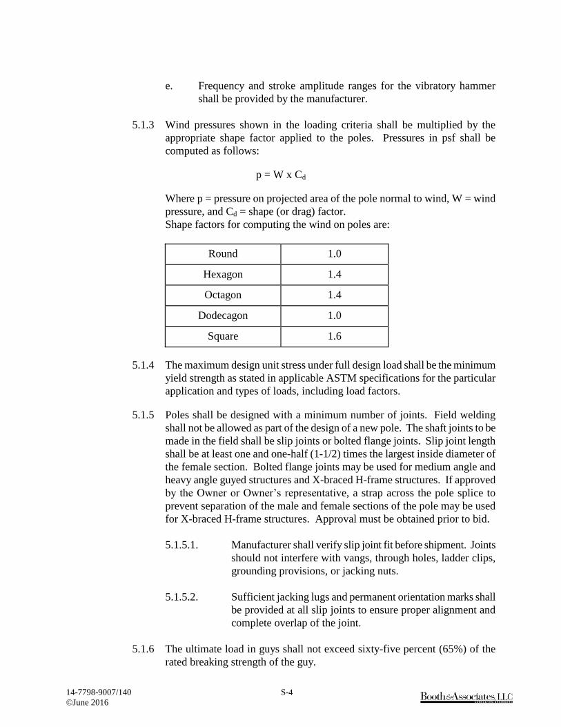
5.1.3 Wind pressures shown in the loading criteria shall be multiplied by the
appropriate shape factor applied to the poles. Pressures in psf shall be
computed as follows:
p = W x Cd
Where p = pressure on projected area of the pole normal to wind, W = wind
pressure, and Cd = shape (or drag) factor.
Shape factors for computing the wind on poles are:
Round 1.0
Hexagon 1.4
Octagon 1.4
Dodecagon 1.0
Square 1.6
5.1.4 The maximum design unit stress under full design load shall be the minimum
yield strength as stated in applicable ASTM specifications for the particular
application and types of loads, including load factors.
5.1.5 Poles shall be designed with a minimum number of joints. Field welding
shall not be allowed as part of the design of a new pole. The shaft joints to be
made in the field shall be slip joints or bolted flange joints. Slip joint length
shall be at least one and one-half (1-1/2) times the largest inside diameter of
the female section. Bolted flange joints may be used for medium angle and
heavy angle guyed structures and X-braced H-frame structures. If approved
by the Owner or Owner’s representative, a strap across the pole splice to
prevent separation of the male and female sections of the pole may be used
for X-braced H-frame structures. Approval must be obtained prior to bid.
5.1.5.1. Manufacturer shall verify slip joint fit before shipment. Joints
should not interfere with vangs, through holes, ladder clips,
grounding provisions, or jacking nuts.
5.1.5.2. Sufficient jacking lugs and permanent orientation marks shall
be provided at all slip joints to ensure proper alignment and
complete overlap of the joint.
5.1.6 The ultimate load in guys shall not exceed sixty-five percent (65%) of the
rated breaking strength of the guy.

14-7798-9007/140 S-5
©June 2016
5.1.7 Design of anchor bolts shall be in accordance with the latest edition of ACI-
318, Building Code Requirements for Reinforced Concrete, assuming a
concrete strength as specified by the Owner.
5.1.7.1 When anchor bolts are specified, they shall have the top two feet
(2′-0″) galvanized. Anchor bolts shall be threaded at the top end
a distance equal to the base plate thickness, plus the thickness of
two (2) anchor bolt nuts, plus two and one-half inches (2-1/2″).
Each anchor bolt shall include two (2) heavy hex nuts.
5.1.7.2 Welding on anchor bolts will only be allowed in the bottom
twelve inches (12″). Only one length of anchor bolt shall be used
on each pole. Anchor bolts/clusters shall have a permanent mark
indicating the structure type, structure number, orientation, and
top of concrete.
5.1.7.3 Anchor bolts shall be designed to be shipped as a rigid cage with
top and bottom plates holding the anchor bolts in place. The
anchor bolt thread shall be protected during shipping. The anchor
bolts shall be welded to the holding plate in the bottom of the
cage. The top template shall be designed to be removable and to
support the assembled cage during lifting and setting operations
without detrimental deformations. Bolt clusters shall be designed
to be rigid enough to withstand the normal jolts of shipping,
handling and installation with no displacement of bolts from the
proper positions within the cluster.
5.1.7.4 The removable template at the top shall have a set of marks to
show the centerline for tangent structures and the angle bisector
for angle structures. If the angle bisector is unclear due to
multiple line angles on the structure, the anchor bolt drawings
must clearly denote the anchor bolt orientation in relationship to
the line angles. The set of marks shall be (2) marks along the
same line 180º to each other. Matching marks are to be on the
base plate of the structure so proper alignment can be made.
5.1.8 Minimum plate thickness for all pole components shall be three-sixteenths
inch (3/16″). Minimum tip diameter for all poles shall be ten inches (10″).
5.1.9 Structures which are to be direct embedded shall have bearing plates.
Bearing plates shall have a diameter not more than two inches (2″) greater
than the maximum pole diameter.
5.1.9.1 Galvanized poles shall have a drain hole at the bottom. The drain
hole shall not be more than 20% of the bottom plate surface area.
14-7798-9007/140 S-6
©June 2016
5.1.9.2 Direct embedded steel poles shall have ground sleeves. Ground
sleeves shall have a minimum length of four feet (4′-0″) centered
at groundline.
5.1.9.3 The Ground sleeve shall have a minimum thickness of three-
sixteenths inch (3/16″) and shall be centered at the ground line.
A seal weld shall be provided around the ground sleeve. The
ground sleeve shall not be considered in strength calculations.
5.1.10 Poles shall have nearly a uniform taper throughout their entire length. The
maximum difference in tapers between two (2) pole sections measured by
the diameters shall be .20 inch/ft. for poles with variable taper.
5.1.11 Poles with elliptical cross sections shall have a minor axis dimension equal
to at least seventy-five percent (75%) of the major axis dimension.
5.1.12 Engineered/Unguyed Structures
Structure deflections at pole top shall be calculated under camber loading.
Structure height shall be the height of the pole from the top of the base plate,
or designated ground line, to the top. See load diagrams or PLS-CADD
printouts, ‘Structure Loads’ column for camber loading.
5.1.12.1 Structures may be pre-cambered if the pole deflection exceeds
one percent (1%). Deflections less than one percent (1%) shall
be raked as necessary in the field. The Materialman shall provide
a pre-cambered summary and clearly denote the pre-camber/rake
orientation on the structure drawings. (Raking is Not Applicable
for this Project)
5.1.12.2 The Materialman shall use the Loading Diagrams provided in
Attachment B or PLS-CADD printouts to design the designated
unguyed structures. The Materialman is responsible for
determining the “worst-case” orientation of the wind load in
combination with the tension and apply it in the design
calculations.
5.1.12.3 The Materialman shall calculate the deflections for the sixty
degrees Fahrenheit (60ºF) initial tension and sixty degrees
Fahrenheit (60ºF) final tension load cases. The Materialman shall
limit the difference in deflection produced by these two (2) load
cases to six inches (6″) or less.
5.1.12.4 Deflections of single-shaft structures under camber loading shall
not exceed one (1.0%) percent of the structure height.

14-7798-9007/140 S-7
©June 2016
5.1.12.5 Deflections of H-Frame structures due to the wire tension change
across the structure and any angle resultant tension, under camber
loading, shall be no more than one half (1/2) the top diameter of
the designed tubular steel pole.
5.1.12.6 Deflections of switch structures under factored loading shall not
exceed two (2%) percent of the structure height under all loading
conditions.
Switch support beams shall be checked for deflection. Engineer’s
drawings will show deflection limitations and/or minimum switch
support beam diameter. (Not applicable for this project)
5.1.12.7 The manufacturer is responsible for repairing or replacing any
structures which are delivered to the site with manufacturing
errors. Repair and/or replacement costs shall include the structure
itself, as well as any associated construction costs.
5.1.12.8 If pole raking is necessary due to deflection, the raking dimension
and orientation shall be clearly marked on the Materialman’s
Detail Drawings.
5.1.12.9 Switch structure equipment loadings and attachment details shall
be obtained by the Pole Manufacturer through coordination with
the specified Switch Manufacturer. (Not applicable for this
project)
5.1.12.10 If shop cambering is required, the manufacturer shall pre-fit
multi-piece poles together prior to cambering.
5.1.12.11 The manufacturer shall verify at the plant prior to shipment that
the appropriate orientation and magnitude of pre-camber is built
into those structures requiring shop cambering.
5.1.13 Standard Class Designations
5.1.13.1 Tangent and guyed angle structures have been specified using
RUS Standard Steel Pole Class Designations shown in Table 1
unless noted otherwise.
5.1.13.2 Pole designs shall be prepared for the attached Standard Class
design loads. The poles shall be designed to meet ASCE Manual
No. 48-11, “Design of Steel Transmission Pole Structures,”
design methods. The point-of-fixity shall be considered to be
located at a distance from the pole bottom that is equal to seven
percent (7%) of the pole length.

14-7798-9007/140 S-8
©June 2016
The pole shall be symmetrically designed such that the strength
required in any one direction shall be required in all directions
about the longitudinal axis.
5.1.13.3 Using the corresponding values in Table 1, the poles shall be
designed for the following requirements.
a. The pole shall develop the minimum ultimate moment
capacity required in Table 1 at a distance of five feet (5′-0″)
from the pole top.
b. The pole shall develop the minimum ultimate moment
capacity above the point-of-fixity that is calculated by
multiplying the tip load in Table 1 by the distance to the tip
load.
c. The geometry and taper of the pole shall be uniform
throughout their entire length (top to butt).
5.1.13.4 The poles shall be designed to withstand the specified tip loading
in Table 1 without exceeding a pole deflection of ten percent
(10%) of the pole length above the point-of-fixity when tested in
accordance with ASCE Manual No. 48-11.
5.1.13.5 Overall length of poles shall be designed and manufactured in
incremental lengths of five feet (5′-0″).

14-7798-9007/140 S-9
©June 2016
TABLE 1
Strength Requirements
Minimum Ultimate Horizontal Tip
Standard Class Moment Capacity at Load Applied 2 ft
Designations 5 ft from Pole Top from Pole Top
for Steel Poles (ft. Kips) (lbs.)
S-20.0 160 20000
S-19.0 152 19000
S-18.0 144 18000
S-17.0 136 17000
S-16.0 128 16000
S-15.0 120 15000
S-14.0 112 14000
S-13.0 104 13000
S-12.0 96 12000
S-11.0 88 11000
S-10.0 80 10000
S-09.0 72 9000
S-08.0 64 8000
S-07.4 57 7410
S-06.5 50 6500
S-05.7 44 5655
S-04.9 38 4875
S-04.2 32 4160
S-03.5 27 3510
S-02.9 23 2925
S-02.4 19 2405
S-02.0 15 1950
5.1.13.6 Poles shall be designed for the loads generated from handling and
erecting without causing permanent deformation or damage
to the pole when handled according to the manufacturer’s
instructions. Handling and erecting loads shall include but not
be limited to, a one (1) point (tilting) pickup and a two (2) point
(horizontal) pickup.
5.1.13.7 The maximum design unit stress shall be the minimum yield
strength as stated in applicable ASTM specifications for the
particular application and types of loads, including overload
factors.
5.1.13.8 The top of the pole shall be permanently covered with a structural
steel plate that is welded to the top of the pole. The pole shall be
delivered with the pole cover attached in place.

14-7798-9007/140 S-10
©June 2016
5.1.13.9 Pole design and design calculations shall be the responsibility of
the manufacturer.
5.1.14 Arms shall be designed so the end of the arm is at the specified height under
a loading of initial conductor tension, sixty degrees Fahrenheit (60ºF), no
wind, and no overload factors. Arms shall not deflect vertically more than
two inches (2″) at the end of the arm under heavy ice conditions (without any
overload factors applied). See Attachment B for Design Loads and Guide
Drawings.
5.1.14.1 Arms shall be upswept or straight, tapered, steel tubular members,
of any cross-sectional type, which meet the dimensions shown on
the attached drawings.
5.1.14.2 Arm end plate connection details for hardware attachment shall
be typical of those shown on the attached drawings. The arms
shall be hermetically sealed when a painted finish is specified.
Galvanized arms shall have drain holes where appropriate
5.1.15 Lifting lugs are optional. The manufacturer shall supply all instructions for
handling and erection of poles and arms.
5.1.16 Deadend plates or vangs shall be designed/checked for the maximum
resultant loading from the appropriate Vertical, Transverse, and Longitudinal
components in the load trees and/or columns labeled “Loads From Back
Span” or “Loads From Ahead Span” in the PLS-CADD printout. All load
cases shall be considered. Do not use the loads from the column labeled
“Structure Loads” for designing/checking vang designs.
5.1.17 In the design of connections for vangs, brackets, or stiffeners attached to the
pole shaft, care shall be taken to distribute the loads sufficiently to protect
the wall of the pole from local buckling.
5.1.18 Thru-vang shall penetrate both sides of the pole with attachment holes on
both sides.
5.1.19 Each pole shall be permanently marked on the pole shaft seventy-two inches
(72″) above ground line and on the bottom of base plate or bearing plate with
the following identifying information:
Manufacturer’s Identification
Structure Type
Height and Class
Structure Number
Ultimate Ground Line Moment
Owner’s Name
14-7798-9007/140 S-11
©June 2016
Date Manufactured
Each Vibratory Pole Base shall be permanently marked on the shaft within
six inches (6”) above the groundline with the following information:
Manufacturer’s Identification
Diameter and Length
Structure Number
Owner’s Name
Date Manufactured
The method of identification shall be approved by the Owner. In addition,
there shall be clear indication or marks for handling or sling points, storage
rack points, and lifting joints for standing the pole and vibratory pole base.
5.1.20 Grounding Attachments
5.1.20.1 One (1), two (2)-hole NEMA grounding pad shall be provided
on the side of each pole as specified in the Structure Dimensions
(Framing Drawings) located in Attachment A.
5.1.20.2 See Attachment D – Drawing No. TMS-5 for NEMA Grounding
Pad Detail.
5.1.20.3 Grounding pads and threads shall not be painted or covered with
other coatings.
5.1.20.4 Poles shall be pre-drilled with a nine-sixteenth inch (9/16)
hole behind each threaded hole of a two (2)-hole NEMA pad to
permit the use of various bolt lengths in completing a grounding
connection.
5.1.20.5 One (1) heavy hex, stainless steel grounding nut shall be provided
where indicated on Structure Dimensions (Framing Drawings).
The grounding nut shall have standard one-half inch (1/2),
thirteen (13) UNC threads. Threads shall not be painted or
covered with other coatings.
5.1.21 Clips for removable ladders shall be located as shown on the enclosed
Framing Drawings or as indicated in the specification. Each ladder clip shall
be designed to support a minimum 1,200 lb. shear working load. The clips
shall be welded to the pole surface. Ladder clips shall be located to avoid
interference between ladders, other attachments, material and equipment to be
mounted on the pole (See Attachment D Miscellaneous Drawings). (Not
applicable for this project)
14-7798-9007/140 S-12
©June 2016
5.1.22 Removable step bolts shall be provided with spacing as indicated beginning
eight feet (8′-0″) above ground line and extending to the structure top. Each
step lug and step bolts shall be capable of withstanding a minimum of 600 lb.
working load. Step bolts mounting nuts shall be spaced at one foot-three
inches (1′-3″) and oriented to provide maximum ease of climbing. (Not
applicable for this project)
5.1.23 Removable pole steps with permanent clips shall be provided as indicated
(Drawing No. PS-1) beginning at ground line and extending to eight feet
(8′-0″) above ground line. Pole steps and clips shall be spaced at one
foot-three inches (1′-3″) and oriented to provide maximum ease of climbing.
(Not applicable for this project)
5.1.24 Weathering steel structures shall be designed to eliminate water and refuse
traps. (Not applicable for this project)
5.1.24.1 Tubular sections shall be sealed from moisture entering the inside
of the pole. Factory drilled pole holes shall be plugged to prevent
moisture intrusion during shipping. For field drilled poles and
factory drilled poles, manufacturer shall provide silicon sealant
to seal all through-bolt holes. Non-drilled poles when assembled
shall be effectively sealed to prevent moisture intrusion.
5.1.24.2 Connections shall be designed to reduce the effect of pack-out
by preventing moisture from entering the joint or by designing
the connection to allow moisture to easily drain off.
5.1.24.3 Plastic plugs shall be installed in all nuts welded to the structure
and all tapped holes.
5.1.25 Application requirements: (See Attachment C)
5.2 Pipe Pile Design (Not applicable for this project)
The design, fabrication, allowable stresses, processes, tolerances, and inspection shall
conform to the latest edition ASTM 252, “Welded and Seamless Steel Pipe Piles” for
the steel pipe pile and the latest edition ASTM A36 for the other associated steel
material. Grade 2 shall be used for the pipe piles.
5.2.1 The pipe pile diameter shall be as indicated on Drawing No. TMF-SPPF in
Attachment A. Piles shall be fabricated as round or 12-sided. The 12-sided
pipe pile diameter shall be measured flat-to-flat.
5.2.2 All welding to be in accordance with the latest edition of AWS D1.1. Use
appropriate electrode for steel grade types (E70 Min.). Circumferential and
longitudinal welds are to be complete-penetration.

14-7798-9007/140 S-13
©June 2016
5.2.3 After fabrication, hot dip galvanize the pile as specified per ASTM A123.
Provide additional holes if needed for handling during galvanizing.
5.2.4 Corrocote shall be applied to pipe pile from top of pile to ten (10’) feet below
top of pile. See paragraph 5.5.1.d Coatings for the Embedded Portion of the
Pole for details.
5.2.5 Pipe piles shall be stamped with one-inch (1”) lettering indicating the
structure number. Stamping shall be done at both ends of the pipe pile.
5.2.6 Pipe pile vendor shall provide the six (6) one-inch (1”) diameter heavy hex
galvanized nuts and six (6) one-inch (1”) diameter by twelve inch (12”) long
galvanized leveling bolts and ensure these nuts and bolts are compatible with
each other. This hardware shall be hot dip galvanized per ASTM A307.
5.2.7 Two (2) hole NEMA grounding pads shall be provided on opposite sides at
two levels of the pipe piles as shown on Drawing TMF-SPPF located in
Attachment A (Total of 4 grounding pads).
5.2.8 Reference Drawing TMF-SPPF for steel pipe pile fabrication details and all
associated materials and hardware.
5.3 Materials
5.3.1 All materials shall comply with the applicable requirements of ASTM
specifications. Any modifications to ASTM specifications must be approved
by the Owner’s representative prior to bidding.
5.3.2 Poles, arms, and conductor brackets shall conform with ASTM A36,
ASTM A572, ASTM A581, ASTM A588, ASTM A871, or ASTM A595.
5.3.3 Base plate shall conform with ASTM A572, ASTM A588, ASTM A633, or
ASTM A595.
5.3.4 Anchor bolts shall conform to ASTM A615, Grade 60 or 75.
5.3.5 Other bolts and nuts shall conform, as applicable, to ASTM A307,
ASTM A325, ASTM A354, ASTM A394, or ASTM A687. Locknuts shall
be provided for each structure bolt, or American Nut Company (ANCO) type
self-locking nuts may be used. Locknuts shall be the galvanized MF or
ANCO type.
5.3.6 Anchor bolts, structural plate, and weld material, shall meet ASCE
requirements for Charpy tests.
5.3.7 For galvanized structures, steel used for the pole shaft and arms shall have a
silicon content less than .06 percent.
14-7798-9007/140 S-14
©June 2016
5.3.8 Steel pipe piles shall conform, as applicable, to ASTM A252. All other steel
material associated with the pipe pile shall conform to ASTM A36.
5.4 Fabrication
5.4.1 All welding shall be in accordance with the American Welding Society Code
AWS D1.1, latest edition. Welders shall be qualified in accordance with
AWS .1 welding procedures.
5.4.2 One hundred percent (100%) penetration welds shall be required in, but not
limited to, the following areas:
circumferential welds (C-welds) joining structural members,
longitudinal welds in the female portion of the joint within the slip joint
area, plus 6 inches;
welds at the butt joints of back-up strips,
base plate to shaft weld,
longitudinal welds for a minimum length of three inches (3″) where there
are adjacent C-welds, flange welds, base welds and ends of tubes.
5.4.3 Full penetration or equivalent ninety percent (90%) partial penetration with
fillet overlap shall be used for arm-to-arm brackets, vang-to-plate shaft, and
arm box joints.
5.4.4 Quality and acceptability of every inch of the full penetration welds shall be
determined by visual and ultrasonic inspection.
5.4.5 All other penetration welds shall have sixty percent (60%) minimum
penetration. Quality and acceptability of all welds other than full penetration
welds shall be determined by visual inspection, supplemented by magnetic
particle, ultrasonic or dye penetrant inspection.
5.4.6 All weld back-up strips shall be continuous the full length of the welds. Care
shall be exercised in the design of welded connections to avoid areas of high
stress concentration which could be subject to fatigue or brittle fractures.
5.4.7 Field welding shall not be permitted except with the Engineer’s and Owner’s
approval and with the manufacturer’s direction in repairing a pole.
5.4.8 All parts of the structure shall be neatly finished and free from kinks or
twists. All holes, blocks, and clips shall be made with sharp tools and shall
be clean-cut without torn or ragged edges.
14-7798-9007/140 S-15
©June 2016
5.4.9 Before being laid out or worked in any manner, structural material shall be
straight and clean. If straightening is necessary, it shall be done by methods
that will not injure the metal.
5.4.10 Shearing and cutting shall be performed carefully and all portions of the
work shall be finished neatly. Copes and re-entrant cuts shall be filleted
before cutting.
5.4.11 All forming or bending during fabrication shall be done by methods that
will prevent embrittlement or loss of strength in the material being worked.
5.4.12 Holes for connection bolts shall be one-sixteenth inch (1/16″) larger than the
nominal diameter of the bolts. Holes in the flange plates for bolted splices
shall be one-eighth inch (1/8″) larger than the bolt diameter. Holes in the
base plates for anchor bolts shall be three-eighths inch (3/8″) larger than the
nominal diameter of the anchor bolts. The details of all connections and
splices shall be subject to the approval of the Owner or his representatives.
5.4.13 Holes in steel plates which are punched must be smooth and cylindrical
without excessive tear out or depressions. Any burrs that remain after
punching shall be removed by grinding, reaming, etc.
5.4.14 Holes of any diameter may be drilled in plate of any thickness. Care shall be
taken to maintain accuracy when drilling stacks of plates.
5.4.15 Holes may be made by use of a machine guided oxygen torch. Flame cut
edges shall be reasonably smooth and suitable for the stresses transmitted to
them.
5.4.16 The overall length of the assembled structure should not be less than six
inches (6″) of the specified length and not more than twelve inches (12″).
5.4.17 Tolerances
Fabrication tolerances shall be as follows:
a. Length of single piece or flanged poles ± 3″
b. Cross section of poles: Diameter of 36″ or less +1/4″, -1/8″.
Diameter greater than 36″ +1/2″, -1/4″, circumference of all poles - 0″
c. Spacing between “arm to pole” connections vertically ± 3/4″
d. Location of hardware with respect to top of pole ± 1″
e. Pole Butt plate perpendicular to pole 1/16″ for 12″ as measured on a
perpendicular axis
14-7798-9007/140 S-16
©June 2016
f. Straightness of pole ± 1/2″ from center line
g. Location of a drilled hole in a piece ± 1/8″
h. Spacing between holes: Base plates ± 1/8″, same connection ± 1/16″
(non-accumulative)
i. Anchor bolts: Length +3″, -0″; thread length +2″, -0″
j. Length of coated portion on anchor bolts +12″, -0″
k. Distance between anchor bolts in cluster ± 1/8″ (non-accumulative)
l. Arms: Length ± 1″, Rise (“W” dimension ± 1″ per 10′ of arm length)
m. Angles shown ± 2°
n. Length of overlap of slip joint, +5″, - 10% of slip joint length
o. Thru Vang Vertical Spacing ± 1/4″
p. Thru Vang Angle and Orientation ± 2°.
5.5 Finishes
5.5.1 The following finishes are acceptable: galvanizing, zinc primer and painting, weathering steel, and below grade coating.
a. Galvanizing – All structures and structural components which are hot-dip galvanized shall meet all the requirements of ASTM A123 or ASTM A153. Measures shall be taken to prevent warping and distortion according to ASTM A384 and to prevent embrittlement according to ASTM A143. Poles made of ASTM A588 steel shall not be galvanized due to the high silicon content of the steel. One (1) gallon of zinc enriched paint shall be provided with each five (5) poles. Provide detailed instructions of proper application and use of zinc enriched paint.
b. Zinc Primer and Painting – Poles which are to be painted shall be
hermetically sealed to prevent corrosion of interior surfaces. After
shot or sand blasting and cleaning in accordance with the Steel
Structure Painting Council’s Surface Preparation Specification,
SSPC-SP6, a zinc primer of three (3) mils dry film thickness (DFT)
and two (2) coats of finish paint, each three (3) mils DFT shall be
applied to all exterior surfaces in accordance with the paint supplier’s
recommendations. One (1) gallon each of primer and finish paint
shall be supplied with each five (5) poles. A guarantee against
flaking or fading of the paint for a minimum of five (5) years shall be
provided. (Not applicable for this project)
14-7798-9007/140 S-17
©June 2016
c. Weathering Steel – Steel shall conform to ASTM A588 or A871.
After fabrication, poles made of weathering steel shall be cleaned
of oil, scale, etc. in accordance with the Steel Structure Painting
Council’s Surface Preparation Specification, SSPC-SP6, to ensure
uniform and rapid formation of the protective oxide layer. (Not
applicable for this project)
d. Coatings for the Embedded Portion of the Pole – When poles are to
be directly embedded, or use a vibratory pole base, a sixteen (16) mil
(minimum dry film thickness), two (2) component hydrocarbon
extended polyurethane coating that is resistant to ultraviolet light
shall be applied on the exposed surface of the embedded portion of
the pole. The coating shall extend from the butt to two feet (2′-0″)
above ground line or to the top jacking nut on the vibratory pole base,
whichever is lower. Other coatings shall be approved by the Owner
prior to their use.
5.5.2 Bolts and nuts with yield strengths under 100,000 psi shall be hot-dip
galvanized per ASTM A153 and ASTM A143, or mechanically coated with
zinc in accordance with ASTM B454, Class 50. Bolting materials with yield
strengths in excess of 100,000 psi shall not be hot-dip galvanized. Instead,
they shall be painted with zinc enriched paint or mechanically coated with
zinc per ASTM B454, Class 50.
5.5.3 Compliance with coating thickness requirements shall be checked with a
magnetic thickness gauge.
5.6 Inspection and Testing
5.6.1 The Owner and the Owner’s designated agents shall have free entry at all
times while work is being carried on, to all parts of the manufacturer’s plant
to inspect any part of the production of the poles covered by this
specification.
5.6.2 Steel members which are bent or warped or otherwise improperly fabricated
shall be properly repaired or replaced at the manufacturer’s expense.
5.6.3 The cost of tests made by the manufacturer (except full scale load tests on
poles), including cost of the certified test reports, shall be considered
included in the price.
5.6.4 The manufacturer shall make tests in accordance with ASTM A370 and
ASTM A673 to verify that the material used in the structures meets the
impact properties.
5.6.5 Mill test reports showing chemical and physical properties of all material
furnished under this specification shall be maintained by the manufacturer for

14-7798-9007/140 S-18
©June 2016
a period of five (5) years and shall be traceable to the structure.
5.6.6 All plates over one and one-half inch (1-1/2″) thick shall be ultrasonically
tested to assure against defects which could lead to lamellar tearing.
5.6.7 Welders or welding operators shall be qualified in accordance with the
provisions of AWS D1.1.
5.6.8 The manufacturer shall make certified welding reports for each structure.
The reports covering welding shall include all welds of a structure. Each
weld shall be clearly identified; and the report shall consist of the method of
testing, whether the weld is acceptable, the identification of the structure,
the date, and the name and signature of the inspector. Records of welding
procedure and welding operator test results shall be kept for six (6) years by
the Materialman and shall be available for review by the Engineer or Owner.
5.7 Structure Testing (Not applicable for this project)
5.7.1 The structures which are to have full-scale load tests performed on them are
listed in Attachment C.
5.7.2 Details of the test procedures and methods of measuring and recording test
loads and deflections shall be specified by the manufacturer prior to testing
and shall be subject to the review and approval of the Owner or his
representative.
5.7.3 Deflections shall be recorded in the transverse and longitudinal directions
when applicable. Deflection measurements shall be taken under the no load
condition both before and after testing.
5.7.4 Material procurement for test poles shall be identical to material procurement
procedures for regular production run poles.
5.7.5 A full report listing the results shall be submitted after completion of all
testing. Copies of mill test reports shall be included in the load test report.
The report shall also include a complete description of the load tests with
diagrams and photographs.
5.7.6 The Owner or his representative reserves the right to be present during testing
and shall be notified two (2) weeks prior to the start of structure fabrication.
5.8 Shipping
5.8.1 Each shipment shall be accompanied by a checklist of all parts, identifiable
by structure type and number. Arms, bolts, and miscellaneous hardware will
be identified by the list for match up with the respective pole shaft and shall
be boxed or bundled. All parts required for any one structure shall be in one
(1) shipment, if possible.
14-7798-9007/140 S-19
©June 2016
5.8.2 The Owner and Owner’s representative shall be notified prior to shipment
that such shipment is to take place, and they reserve the right to inspect the
components prior to shipment. The notification shall give quantities; weight,
name of common carrier used, and expected time of arrival with at least
two (2) working days’ notice of delivery. Delivery of all items of material
shall be made at such time as to permit unloading between the hours of 9:00
a.m. and 3:00 p.m., Monday through Thursday, holidays excluded.
5.8.3 The anchor bolts shall be welded to the holding plate in the bottom of the
cage. A removable template shall be used at the top of the cage and shall be
marked to show the centerline for tangent structures and the angle bisector
for angle structures. Matching marks are to be on the base plate so proper
alignment can be made. Bolt clusters shall be rigid enough to withstand the
normal jolts of shipping and handling with no displacement of bolts from the
proper positions within the cluster.
5.8.4 Unless otherwise agreed to by the Owner, the anchor bolt cage shall be
shipped at least thirty (30) days prior to pole shipment.
5.8.5 Salt-treated wood blocking and urethane foams shall not be used when
shipping or storing weathering steel poles.
5.8.6 Delivery shall be made either to a single designated location or to the
individual structure locations.
6.0 INFORMATION TO BE SUPPLIED BY THE MANUFACTURER
6.1 Information to be Supplied with the Proposal
a. Calculated shipping weight of each structure and pipe pile excluding anchor
bolts. Separate weights shall be given for crossarms and poles.
b. Calculated shipping weight of anchor bolts,
c. Ultimate ground line reactions (including overload factors) in poles and guy
wires,
d. Anchor bolt size, length, and locations (bolt circle diameters)
e. Type of material of major components (ASTM number),
f. Description of pole and pipe pile shaft, including thickness, length, diameter,
cross-sectional geometry, and method of fastening each shaft component,
g. Data showing the design of the arm, arm connections, arm attachment plates,
and brackets,
h. Design exceptions,
14-7798-9007/140 S-20
©June 2016
i. Manufacturer’s standards, physical and mechanical dimensions for all steel
pole height and class combinations used in the project being bid on.
6.2 Documentation to be Supplied for the Owner’s Approval Prior to Fabrication
Documentation includes final design calculations for pole shaft, base plate, anchor
bolts, crossarms, and other appurtenances, including their connections for all
structures. The following information shall be supplied:
a. For the loading cases with overload factors, the total shear, axial forces,
moments, stresses or stress ratios, moments of inertia furnished, section
moduli, cross-sectional areas, deflections w/t’s for polygonal and d/t’s for
round cross sections at all splices, at arm attachment points (top and bottom),
and at least every ten feet (10′-0″) along the pole.
b. For the critical loading case, shear and axial forces, moments, stresses,
section moduli, cross-sectional areas at the arm connections, bolt stresses in
the arm connection, and deflection at the end of the arm.
c. Anticipated deflections at the top of the pole and at the ends of the arms shall
be indicated for each pole for the normal, everyday loading condition of sixty
degrees Fahrenheit (60ºF), no wind, no overload factors.
d. For all specified loading cases, reactions and ground line moments shall be
supplied.
e. Detail drawings for each structure type giving weights of structure
components, dimensions, and bill of materials.
f. Assembly instructions and erection drawings. Slip joint lengths and
allowable tolerances. Special handling instructions.
6.3 Final Documents shall be supplied to the Owner for the items in paragraph 6.2.e.
after erection of all structures and prior to final payment
6.4 Test Reports (as requested)
a. Certified mill test reports for all structural material,
b. Certified welding reports for each structure,
c. Impact property test reports showing that the material used in the structures
meets the impact properties,
d. Test reports on coating thickness,
14-7798-9007/140 S-21
©June 2016
e. Report of structure testing, when required, including photographs, diagrams,
load trees, etc.,
f. Material, workmanship, inspection travelers, and material certified mill test
reports shall be maintained on file for a minimum of six (6) years by the
Materialman, and shall be made available to Greenville Utilities Commission
or the Engineer upon request at no charge.
7.0 APPROVAL, ACCEPTANCE, AND OWNERSHIP
7.1 Final designs must be approved by the Engineer before material ordering and
fabrication. Material ordering and fabrication prior to approval will be at supplier’s
risk. It is understood that award of this contract does not constitute acceptance of
design calculations submitted with the bid, if corrections are required in the final
structure designs due to manufacturer’s errors, omissions, or misinterpretations of
the specifications, the quoted price shall not change. Approval of the drawings and
calculations by the Engineer does not relieve the supplier of responsibility for
the adequacy of the design, correctness of dimensions, details on the drawings, and
the proper fit of parts.
7.2 After delivery, the poles will be inspected and shall be free of dirt, oil blisters, flux,
black spots, dross, tear-drop edges, flaking paint or zinc; and in general, shall be
smooth, attractive, and unscarred. Poles not meeting this requirement shall be
repaired or replaced by the fabricator at no additional cost to the Owner.