griffith aviation assignment: 2505 bps...
TRANSCRIPT

Page 1 of 18
Griffith Aviation
Assignment: 2505 BPS
Aerodynamics
Due:1700 26 September 2014
Accident Report: Loss of Control involving
SOCATA TB 20, VH-HBB
Weight: 30%
Word Count: 3475 words
(excluding Executive Summary, Recommendations and Bibliography)
Student Name Lok-Hin Li Rebecca Spencer Mitchell Tynan Michelle Shiels
Student Number S2942252 S2942503 S2941977 S2942509

Page 2 of 18
Executive Summary
This paper will examine the occurrence of a wing drop stall experienced by a Socata TB-20 on
November 9, 2012 at Lismore Aerodrome, NSW. The Australian Transport Safety Bureau (ATSB)
finalised their report on 11 March 2014 (AO-2012-149), which provided much of the
information on the context of the incident, the experience of the pilots and the circuit used by
the aircraft, as well as eye-witness accounts. In addition to this information, this paper
outlines the principles involved in the generation of lift as well as exploring stall speeds in
depth, covering cross-control stall, the effects of the use of flaps, accelerated stall speeds and
stall recovery techniques. It concludes with a determination of the contributing factors for the
occurrence, as well as a short list of recommendations for the improvement of safety.
Table of Contents
1 INTRODUCTION ................................................................................................................................... 3
1.2 Definitions ..................................................................................................................................... 3
1.3 Context of the Occurrence ........................................................................................................ 3
2 PILOT EXPERIENCE ............................................................................................................................... 4
3 CIRCUTS................................................................................................................................................ 5
4 GENERATION OF LIFT ........................................................................................................................... 6
4.2 Why the inside wing stalls before the outer wing on descent ..................................................... 8
5 STALL SPEEDS ....................................................................................................................................... 8
5.2 Cross-Control Stall ......................................................................................................................... 9
5.3 Extension of Flaps ..................................................................................................................... 9
5.4 Load Factors ....................................................................................................................... 11
5.5 Accelerated Stall Speeds .......................................................................................... 12
5.6 Stall Recovery ................................................................................................ 13
6 CONTRIBUTING FACTORS .................................................................................................................. 13
7 RECOMMENDATIONS ........................................................................................................................ 14
8 REFERENCES ....................................................................................................................................... 16

Page 3 of 18
1 INTRODUCTION
This paper will examine the series of events that led to the aerodynamic stall of a SOCATA TB-20 on
November 9, 2013 in Lismore NSW. After a brief overview of the occurrence, it evaluates the
experience of the pilots, the circuit plan utilised in the incident, how lift is generated, the various
ways in which a stall may have been induced in this instance and recovery techniques that could
have prevented the tragic outcome. Contributing factors are then summarised and used to form a
brief list of recommendations that could prevent the occurrence of similar incidents in future
operations.
1.2 Definitions
Bank: To tilt an aircraft laterally and inwardly in flight.
Circuit: A circuit is a standard flight pattern used around an airport that consists of 5 legs –
upwind, crosswind, downwind, base and final forming a complete rectangle.
KCAS: Knots Calibrated Air Speed.
Stall: A condition where the angle of attack of an aircraft increases beyond a certain point
such that the lift begins to decrease.
1.3 Context of the Occurrence
The incident occurred on November 9, 2012 as a student pilot and his instructor joined the
Lismore circuit in a Socata TB-20, registered VH-HBB, belonging to the student. This was a
planned flight for the student’s conversion to the TB-20. The ATSB verified that the aircraft
departed from Gold Coast Airport at 0929 Eastern Daylight-saving Time travelling in a
southerly direction. Upon being west of Byron Bay the aircraft turned and headed in a south-
westerly direction. Radar contact was lost 10NM north-north-east of Lismore due to radar
limitations for low-level flying (ATSB, 2014). Radio contact was re-established on the
Lismore common traffic advisory frequency (CTAF) as the aircraft was 8NM north of
Lismore Airport.

Page 4 of 18
At 0949, VH-HBB entered the Lismore circuit on the downwind leg and proceeded to
complete four circuits. At approximately 1015, upon entering the downwind leg of their fifth
circuit, it was observed from the Bruxner Highway that the aircraft had suddenly banked
significantly to the left, indicating a stall, and descended at a rapid rate. Based on eye-witness
accounts, the pilots seemingly regained partial control as it passed mere metres above the
highway. The nose of the aircraft began to raise but the aircraft remained unsteady until it
impacted the ground in a south-easterly direction in a paddock east of the highway and
skidded 170m before coming to a halt inverted. The ATSB found that the aircraft had hit a
wired fence that ruptured a wing fuel tank and began releasing fuel that shortly ignited. The
engine was also separated from the aircraft upon contact with a mass of earth a metre after
hitting the fence (ATSB, 2014). Both the student pilot and his instructor were killed in the
event.
2 PILOT EXPERIENCE
The aircraft was manned by two pilots at the time of the occurrence, a student pilot and his
instructor.
The student pilot began to train part time in 2007. Between January 2007 and December
2009 he flew regularly, passing the General Flying Progress Test 22 February 2008 and
commencing his training for the Private Pilot (Aeroplane) License thereafter. In December
2009, the student’s flying became erratic, with his flights sometimes being three or four
months apart. This resulted in a degradation of his skills, recorded by his flight school as
being a tendency to overuse the aileron and rudder controls on landing, a need for guidance in
controlling the aircraft’s attitude and airspeed and a difficulty with keeping the aircraft in
balance (ATSB, 2014, p.5). As a result, the flight school imposed special conditions on his
solo flights. Up until this point, in mid-2012, all of the student’s flight experience had been in
the Cessna 172.
On the 25 September 2012 the student recommenced his training in the SOCATA TB 20 at
a different flight school. At the time of the occurrence, the student had accumulated 138.7
hours of flying time, just 8.5 of which were in the TB 20, the rest of which had been in the C-
172 (ATSB, 2014, p.4).

Page 5 of 18
The student’s instructor held a Commercial Pilot (Aeroplane) License and a Grade 1 Flight
Instructor Rating. He had a total of 3,996.2 flying hours, more than 2,200 of which had been
in the C-172 (ATSB, 2014, p.6). He also had experience flying the Cessna 152, Cirrus SR20
and SR22 and Beech BE-76. At the time of the occurrence, he had just 9.6 hours in the TB
20. This included a 1.1 hour maintenance flight that he completed prior to the commencement
of the student’s training, during which he successfully performed recovery from aerodynamic
stalls.
The final record left by the instructor (2 November 2012) stated that that student pilot still
required “constant direction” when flying (ATSB, 2014, p.5).
3 CIRCUTS
The circuit plan used for the flight was for a Cessna C172. No notes were found for a TB-20
as it was not part of the flying school’s fleet. The notes had information about speeds and
altitudes at different points of the circuit as listed from the ATSB (ATSB, 2014, p.17):
“Late downwind: 85 KCAS at 1,000 ft
Base: 75 KCAS at 750ft
Final: 65 KCAS at 500 ft”
Student Pilot Flying Hours
Cessna 172 -178.2 hours
SOCATA TB 20- 8.5 hours
Instructor Flying Hours
Cessna 172 - >2200 hours
TB 20 - 9.6hours
Other -approx.1786.6 hours

Page 6 of 18
(ATSB, 2014, p.17)
The notes were compliant with the Aeronautical Information Publication (AIP) Australia
where they recommend a normal circuit height of 1,000ft for medium performance aircraft
for non-controlled aerodromes and descent to the runway should begin when turning into
base (Airservices Australia, 2014). The speeds, however, were consistent with operations for
a Cessna 172 (Cessna Aircraft Company, 1977, p. 4.3). Of particular significance is the
reduction in speed to 85 KCAS as the aircraft turned from base to final on descent. Although
well above the accelerated stall speeds of a C-172, it is dangerously close to the stall speed of
a TB-20. If the pilot, who was inexperienced and noted by the flight school as experiencing
difficulties maintaining consistent airspeeds, made even a small error with either his speed or
angle of attack, there was very little room for error before the accelerated stall speed of his
aircraft was met.
4 GENERATION OF LIFT
There are many factors that contributed to the TB20 crash including the amount of lift
generated by the wings and the wing stall itself. One theory that describes how lift is
generated is explained by NASA who states that it is derived from two air molecules
travelling over the aerofoil at the same time. As the upper streamline air molecule travels a
longer distance in the same amount of time to the lower streamline air molecule, the velocity
differences cause a difference in pressure according to Bernoulli's equation of:
Static Pressure + Dynamic Pressure = Total Pressure
The velocity of the upper streamline is higher which causes lower pressure above the
aerofoil, this is the reverse underneath the airfoil. Air molecules in high pressure want to
Page 7 of 18
travel to lower pressure regions, this causes an upward force on the airfoil resulting in lift
(http://www.grc.nasa.gov/WWW/k-12/airplane/wrong1.html).
Lift = CL 1
2 ρ V2 S (Tait, 2011)
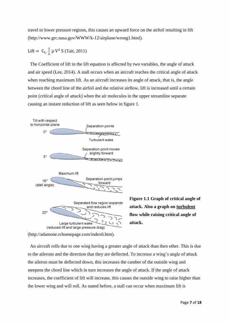
The Coefficient of lift in the lift equation is affected by two variables, the angle of attack
and air speed (Lee, 2014). A stall occurs when an aircraft reaches the critical angle of attack
when reaching maximum lift. As an aircraft increases its angle of attack, that is, the angle
between the chord line of the airfoil and the relative airflow, lift is increased until a certain
point (critical angle of attack) when the air molecules in the upper streamline separate
causing an instant reduction of lift as seen below in figure 1.
Figure 1.1 Graph of critical angle of
attack. Also a graph on turbulent
flow while raising critical angle of
attack.
(http://adamone.rchomepage.com/index6.htm).
An aircraft rolls due to one wing having a greater angle of attack than then other. This is due
to the ailerons and the direction that they are deflected. To increase a wing’s angle of attack
the aileron must be deflected down, this increases the camber of the outside wing and
steepens the chord line which in turn increases the angle of attack. If the angle of attack
increases, the coefficient of lift will increase, this causes the outside wing to raise higher than
the lower wing and will roll. As stated before, a stall can occur when maximum lift is

Page 8 of 18
reached. As one wing may have a greater angle of attack, one wing may stall before the other
which will be discussed further in detail as the contributing event that caused the TB20 to
crash.
Why the inside wing stalls before the outside wing on descent
Figure 1.1 portrays an aircraft wings in relevance to altitude during a climb or descent. It can
be seen that the relative downward force acting on the aircraft's wings will remain the same
as the altitude difference stays neutral. Figure 1.2 shows the difference in angle of attack
between the outside wing and the inner wing during a descending turn. It can be seen that
during the descending turn the inner most wing has a greater angle of attack. Both wings have
the same amount of downward force acting on the relative airflow however, the outer wing is
travelling further than the inner wing during the turn. This creates a larger forward force
acting on the relative airflow for the outer wing causing the angle of attack to be greater for
the inner wing. This leads to the inner wing stalling before the outer wing during a
descending turn. This corresponds with the TB20 incident as witness described the aircraft in
a left descending turn when the bank of the aircraft suddenly steepened and started to spiral.
Figure 1.2 Why a plane’s inner wing stalls first
5 STALL SPEEDS
The ATSB accident report (2012) stated that the aircraft experienced an aerodynamic stall
during a left turn in the circuit pattern, at low altitude. It was noted that the left wing dropped,
that is stalled before the right wing, and the aircraft had a nose down attitude as it descended
steeply (ATSB, 2012).
Exceeding the stalling angle sees to a rapid loss in lift. This angle could have been exceeded
due to factors such as wind gusts or pilot control inputs. An aircraft would experience a rapid

Page 9 of 18
decrease in lift on one side if it encountered a wind gust while operating near the stall angle
(Tait, 2011). This results in a wing drop, which is what TB20 experienced. As a wing drop
progresses, the aircraft rolls at an accelerated rate from the increase in the angle of attack.
5.2 Cross-Control Stall
If the turn was unbalanced, by a sideslip causing a sidewards acceleration, this also would
have increased the tendency for the left wing to drop, causing the aircraft to roll leftwards as
well (Federal Administration of Aviation, 2004). In The Report, it was noted that upon
impact, the aircraft was directed leftwards of its line of travel, “with a right sideslip” (ATSB,
2012, p. 7). Furthermore, if inputs to the aileron and rudder were applied in opposite
directions, the aircraft may have experienced a cross-control stall (ATSB, 2012). This stall
occurs without great warning, causing the inside wing to drop suddenly and possibly continue
into a roll. The FAA stated that "recovery may be impossible" (2004) during the low altitude
associated with a landing approach, which the TB20 was nearing.
A cross-control stall may also be induced by excessively applying back pressure on the
elevators. This type of stall is more likely to occur during a poor turn when approaching from
base to final. The FAA state that "improperly trained pilots may be apprehensive of
steepening the bank to increase the rate of turn" (2004), which would raise the likelihood of
stalling as the aircraft’s load factor increases (Lee, 2014). When a cross-control stall is
demonstrated, the FAA recommends having the landing gear down but no extension of flaps
(2004). This may have added to the inability for recovery, as the TB20 aircraft had flaps fully
extended to the 40˚ landing configuration (ATSB, 2012).
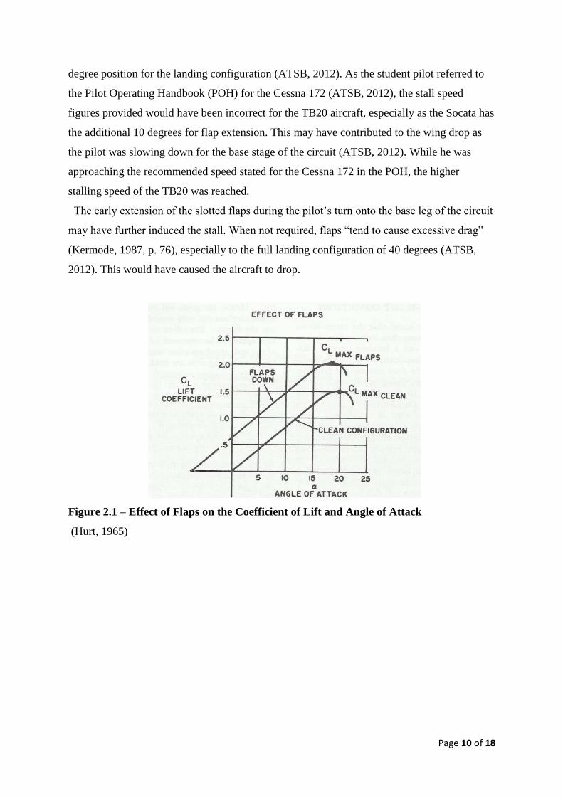
5.3 Extension of Flaps
In reference to Figures 2.1 and 2.2 (Hurt, 1965) below, it can be seen that the extension of
flaps will increase the coefficient of lift but slightly decrease the critical angle of an aircraft,
hence the stall speed is reduced. Figure 2.2 further indicates that a greater increase in the
maximum lift coefficient has a greater reduction in the stall speed, representing an inverse
relationship between the two factors. The Socata TB20 is fitted with single-slot trailing edge
flaps (ATSB, 2012). These flaps differ from those of the Cessna 172 model, which is
equipped with single-slotted Fowler flaps and have incremental changes of 0, 10, 20 and 30
degrees (Cessna Sales and Services, 1967). The Socata TB20 also has degree changes
between 0 and 10 degrees for the take-off configuration but an additional increment to a 40
Page 10 of 18
degree position for the landing configuration (ATSB, 2012). As the student pilot referred to
the Pilot Operating Handbook (POH) for the Cessna 172 (ATSB, 2012), the stall speed
figures provided would have been incorrect for the TB20 aircraft, especially as the Socata has
the additional 10 degrees for flap extension. This may have contributed to the wing drop as
the pilot was slowing down for the base stage of the circuit (ATSB, 2012). While he was
approaching the recommended speed stated for the Cessna 172 in the POH, the higher
stalling speed of the TB20 was reached.
The early extension of the slotted flaps during the pilot’s turn onto the base leg of the circuit
may have further induced the stall. When not required, flaps “tend to cause excessive drag”
(Kermode, 1987, p. 76), especially to the full landing configuration of 40 degrees (ATSB,
2012). This would have caused the aircraft to drop.
Figure 2.1 – Effect of Flaps on the Coefficient of Lift and Angle of Attack
(Hurt, 1965)

Page 11 of 18
Figure 2.2 – Effect of Maximum Coefficient of Lift on Stall Speed (Hurt, 1965)
5.4 Load Factors
As an aircraft turns (at constant altitude), gravity and centrifugal force act upon its load
factor. The Rate of Turn (ROT) for any given banking angle will increase as airspeed
increases, and vice versa, as depicted in figure 3.1.
Figure 3.1 (AboutFlight.com, 2014)
After reaching a 45 degree angle of bank, the load factor of the aircraft increases
dramatically (Robson, 2013, p. 111). As seen in the graph depicted in Figure 3.2, a 60 degree
angle of bank will result in a load factor of 2 Gs.

Page 12 of 18
Figure 3.2 (AboutFlight.com, 2014)
The greater the load factor, the greater the lift that the wing must produce to stay aloft. This
lift must be provided by additional thrust. As a rule, the stall speed of an aircraft will increase
by the square root of the load factor as the aircraft is turning (Robson, 2013, p. 112).
The weight of the TB-20 at the time of the stall is estimated to have been 1,250 kg, well
below its maximum take-off weight of 1,400 kg (ATSB, 2014, p.7). However, if the aircraft
achieved a 45 degree angle of bank as it turned, its resulting weight would be 1762.5 kg, and
if it went so far as to bank at 60 degrees, its weight at the time of the event would have been
doubled to 2500 kg. As a result, the stall speed would have risen by anything between 1.19
and 1.41 times during the turn, depending upon the angle of bank. In such a situation, it is
likely that the aircraft experienced an accelerated stall.
5.5 Accelerated Stalls
Stall speeds outlined in the aircraft operating manual apply to straight and level flight,
however stalling may occur at higher speeds when the aircraft is experiencing the application
of excessive control. One example of this would be when the aircraft is being banked steeply
into a turn. These types of stalls are usually sudden and severe (Katz, 2008). As the angle of
attack of a wing increases, so does its G-loading. For example, when the angle of attack is 60
degrees, the loading factor reaches 2 Gs and the stall speed will be equivalent to the square
root of 2 (which is 1.41), multiplied by the straight and level stall speed.

Page 13 of 18
If we take the stall speeds of the C-172 and the TB-20 (full flap extension), they are 48
KCAS and 59 KCAS respectively (Cessna Aircraft Company, 1977, p.ii and EADS Socata,
1988, p.5.5). Multiplied by 1.41 to account for the G-loading of a wing banked in a 60 degree
turn, we get an accelerated stall speed of 68 KCAS for the C-172 and 83 KCAS for the TB-
20. Had the student pilot been flying a C-172, the circuit plan being used would have allowed
for a wide margin of error on approach. However, the accelerated stall speed of the TB-20
was dangerously close to the speed that the student pilot was directed to fly at entering the
downwind phase of the circuit, which was 85 KCAS, according to the C-172 circuit plan
being implemented by his flight school. The slightest error in speed or angle of bank would
be enough to induce a stall.
5.6 Stall Recovery
A manufacturer of the aircraft had previously noted that the aircraft's nose tended to pitch
down and the bank angle would remain "very close to the initial value if less than 60˚"
(ATSB 2012, p.8), if in a left turn at the time of the stall. It was also mentioned that the
aircraft had a tendency to enter a spiral dive if the bank angle exceeded 60˚. Manufacturers
further stated that the aircraft's attitude, as mentioned by witnesses, would see to a "descend
up to 800 ft before being able to be fully recovered from the stall" (ATSB, 2012, p. 8). If the
TB20 was making the left turn to enter the base phase of the circuit, its altitude would have
been reducing, leaving less height for potential recovery.
In terms of stall recovery for the TB20, having the centre of gravity closer to the aft limit
(ATSB, 2012) may have led to wing rocking or a wing drop. An estimation of the aircraft's
weight and balance found the centre of gravity to be near its rear limit during the flight
(ATSB, 2012). It was noted that prompt application of power and an immediate raising of the
controls would provide effective recovery. This would have all depended on the pilot’s
accuracy in interpreting the situation and his reaction time.
6 CONTRIBUTING FACTORS
A degradation of skills in the student pilot due to the irregularity of his training (as
noted by his initial flying school).

Page 14 of 18
The student pilot’s decision to change to another flight school meant that the
conditions that his initial flight school had placed upon him in response to the
difficulties he was experiencing with his training no longer had to be applied.
The student pilot’s difficulty keeping the plane in balance and maintaining speed (as
recorded by his initial flight school), combined with the probable use of a circuit plan
that called for him to bank at speeds that were within a 2 knot range of the accelerated
stall speed of the aircraft type he was flying.
The difference in flap extension between the TB-20 and the C-172 meant that when
the pilot extended the flaps for landing, they extended not to the 30 degrees
anticipated by the C-172 circuit plan but to 40 degrees. This 10 degree difference
would have increased drag and in turn stalling speed for the aircraft.
Failure of the pilots to recognise the wing-drop stall in time to apply correct stall
recovery techniques. The TB-20 is fitted with a stall warning system that should have
sounded 5-10 knots before stall speed (EADS Socata, 1988, p.4.21). The inability of
the student pilot, and more significantly, his more experienced instructor, to react to
this stall warning in time indicates that the reduction in speed and induction of the
stall happened at a rapid rate. The rapid rate at which the aircraft lost air speed
prevented the pilots from performing recovery techniques. Had flaps been retracted,
power increased and controls raised as soon as the stall was identified, the aircraft
may have recovered from the stall (ATSB, 2012).
The failure of the flight school to provide a circuit plan for the aircraft type being used
(the TB 20) meant that both the student and instructor probably relied upon their
knowledge of the circuit plan for the C-172, and aircraft that both pilots were familiar
with. However, accelerated stall speeds for the TB 20 and C-172 are different, as are
flap configurations (with the TB-20 having 10 degrees greater extension than the C-
172) and so the C-172 circuit plan did not allow for much room for error when
banking the TB 20, which has a significantly higher stall speed than the C-172.
7 RECOMMENDATIONS
The development and implementation of a CASA regulated centralised database for
student records that is a mandatory requirement for all flight schools and that is
accessible to any registered flight instructor in Australia. This will ensure that

Page 15 of 18
instructors are able to see the flight history of their students, along with any special
conditions that were imposed upon them by other flight schools, and make an
informed decision on the best way for their training to proceed.
The introduction of a brief, compulsory theory test for instructors to be completed
prior to taking students out in an aircraft that is unfamiliar to them. This test should
cover vital information that is specific to the aircraft (such as accelerated stall speeds)
and be retained by the flight school for their records.
The development and implementation of CASA regulations making it mandatory for
flight schools to provide circuit plans that are specific to the aircraft being used by the
student pilot.

Page 16 of 18
8 REFERENCES
AboutFlight.com (2014). Load Factors in Steep Turns. Retrieved 25/09/14 from
http://www.aboutflight.com/handbook-of-aeronautical-knowledge/ch-4-aerodynamics-of-
flight/load-factors
Airservices Australia (21 August 2014). Aeronautical Information Publication (AIP).
Retrieved from http://www.airservicesaustralia.com/
Australian Transport Safety Bureau (ATSB) 11 March 2014. Aviation Occurrence
Investigation AO-2012-149.
Cessna Sales and Services. (1967). Model 172 and Skyhawk Owner’s Manual. Red Sky
Adventures. Retrieved from
http://www.redskyventures.org/doc/cessna-
poh/Cessna_172_C172H_1967_POH_scanned.pdf
Cessna Aircraft Company (1977). Pilot’s Operating Handbook Cessna Model 172N.
Retrieved 25/09/14 from http://alameda-aero.com/wp-
content/uploads/2013/05/Cessna172NPOH.pdf
EADS Socata (1988). TB-20 Pilot’s Information Manual. Retrieved 25/09/14 from
http://www.travisaeroclub.com/tb20poh.pdf
Experimental Aircraft Info. (2014). Factors affecting stall speeds. Retrieved from
http://www.experimentalaircraft.info/flight-planning/aircraft-stall-speed-1.php
Hurt, H. H. (1965). Aerodynamics for naval aviators. California, United States of America:
University of Southern California.
Federal Administration of Aviation. (2004). Slow Flight, Stalls and Spins. Retrieved from
https://www.faa.gov/regulations_policies/handbooks_manuals/aircraft/airplane_handbook/me
dia/faa-h-8083-3a-3of7.pdf

Page 17 of 18
Katz, Peter. (June 24, 2008). The Accelerated Stall in “Plane and Pilot.” Retrieved
25/09/2014 from http://www.planeandpilotmag.com/pilot-talk/ntsb-debriefer/the-accelerated-
stall.html
Kermode, A. C. (1987). Flight Without Formulae. Essex, England: Long Scientific &
Technical.
Kluga, N. R. (1991). A Study of Flap Management, an Analysis of the Consequences of Flap
Management, and a Search for Possible Causes. The Journal of Aviaiton / Aerospace
Education & Research. 1(3). Retrieved from
http://commons.erau.edu/cgi/viewcontent.cgi?article=1026&context=jaaer
Lee, P. (2014). 2505BPS Aerodynamics Week 8 Lecture: Stalling. Retrieved from Griffith
University, School of Biomolecular and Physical Sciences, Learning@Griffith web site:
https://bblearn.griffith.edu.au/bbcswebdav/pid-1112349-dt-content-rid-
3096244_1/courses/2505BPS_3145/2505%20BPS%20-
%20Stalling%20%28week%208%29.pdf
PilotFriend.com (2014). Retrieved 25/09/14 from
http://www.pilotfriend.com/aircraft%20performance/aerospatiale/7.htm
Robson, D. (2013). Basic Aeronautical Knowledge (BAK). Queensland, Australia: Aviation
Theory Centre Pty Ltd.
Socata TB20 Trinidad: Aircraft choice. (2014). Retrieved from
http://www.peter2000.co.uk/aviation/tb20-experience/
Tait, B. (2011). CPL Aerodynamics. Redcliffe, Australia: Bob Tait's Aviation Theory School
The University of Waikato Science Hub. (2011). Science Learning: Wing loading Retrieved
from http://www.sciencelearn.org.nz/Contexts/Flight/Science-Ideas-and-Concepts/Wing-
loading

Page 18 of 18