griffon 2000tdx - john-tom.com · griffon 2000tdx 1/10 scale model by mark porter general the...
TRANSCRIPT

Griffon 2000TDX
1/10 Scale model by Mark Porter
General
The instructions and diagrams on these pages will show you how to make a working, scale model of a hovercraft.
Construction notes.
The appearance and performance of this working model will depend to a large extent on the care taken in building the model and the accuracy with which the parts are cut out. Balsa parts should be cut with a sharp modelling knife, or a razor saw for thicker parts. A "Stanley" knife with a new blade is ideal for cutting the 0.8mm plywood. As always, safety must be considered when using knives, and when using glues and paints.
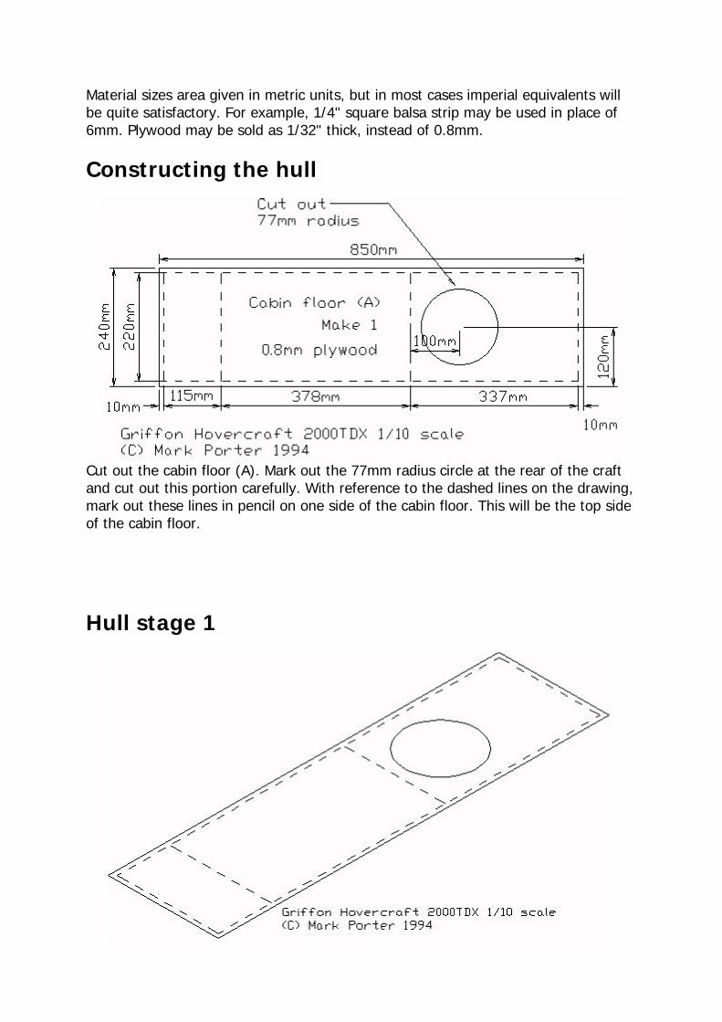
Material sizes area given in metric units, but in most cases imperial equivalents will be quite satisfactory. For example, 1/4" square balsa strip may be used in place of 6mm. Plywood may be sold as 1/32" thick, instead of 0.8mm.
Constructing the hull
Cut out the cabin floor (A). Mark out the 77mm radius circle at the rear of the craft and cut out this portion carefully. With reference to the dashed lines on the drawing, mark out these lines in pencil on one side of the cabin floor. This will be the top side of the cabin floor.
Hull stage 1

Constructing the hull
Cut out four bulkheads (B). Cut the 6mm square balsa strip as shown in the drawing and glue to one side of each bulkhead (B) with PVA and leave to dry. When dry, turn each part (B) over and repeat on the other side.
Hull stage 2
Lay the cabin floor (A) on a flat surface. Glue the four bulkheads (B) to the cabin floor (A) with PVA and pin in place. The bulkheads stand on the four dashed lines across the cabin floor (A). Prop up the bulkheads while the glue dries. Remove the pins when the glue is dry.
Constructing the hull
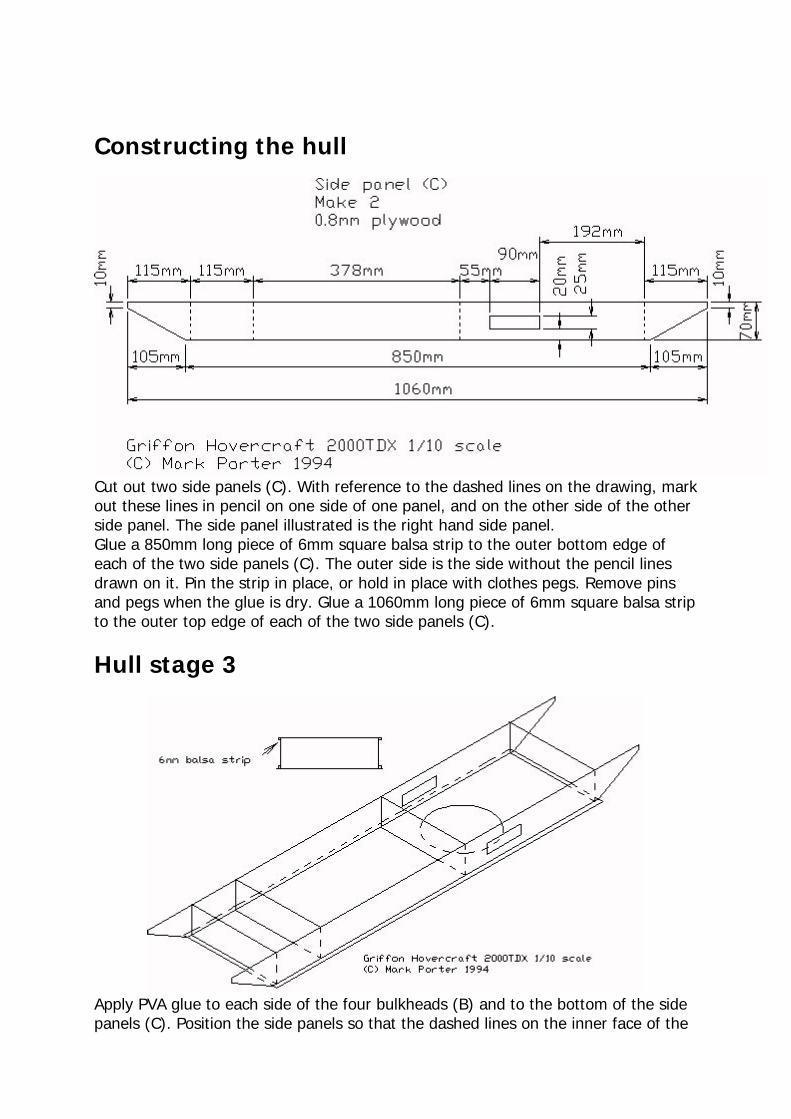
Cut out two side panels (C). With reference to the dashed lines on the drawing, mark out these lines in pencil on one side of one panel, and on the other side of the other side panel. The side panel illustrated is the right hand side panel. Glue a 850mm long piece of 6mm square balsa strip to the outer bottom edge of each of the two side panels (C). The outer side is the side without the pencil lines drawn on it. Pin the strip in place, or hold in place with clothes pegs. Remove pins and pegs when the glue is dry. Glue a 1060mm long piece of 6mm square balsa strip to the outer top edge of each of the two side panels (C).
Hull stage 3
Apply PVA glue to each side of the four bulkheads (B) and to the bottom of the side panels (C). Position the side panels so that the dashed lines on the inner face of the
side panels line up with the bulkheads and the bottom of the side panels lines up with the dashed lines along the edge of the cabin floor (A). Pin the side panels in place and remove the pins when the glue is dry.
Constructing the hull
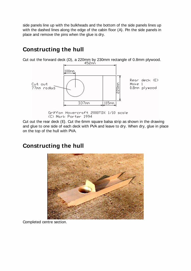
Cut out the forward deck (D), a 220mm by 230mm rectangle of 0.8mm plywood.
Cut out the rear deck (E). Cut the 6mm square balsa strip as shown in the drawing and glue to one side of each deck with PVA and leave to dry. When dry, glue in place on the top of the hull with PVA.
Constructing the hull
Completed centre section.

Fitting the lift motor unit
The inner wall of the lift duct is made from a sheet of 0.4mm plywood, with the grain of the outer faces running along the longer dimension. Gently roll the duct wall and fit in place. Mark the overlap and remove the duct wall. Glue the duct joint along the overlap line. When the glue is dry, fit in place and then fix with glue. A 90mm by 25mm rectangular slot must be cut in each side, 25mm from the top edge of the duct. Use balsa sheet to make a rectangular tube to join the duct slots to the craft outer wall. This will allow air to flow into the skirt. Fit the motor to a 25mm wide piece of 1.6mm plywood. Position face down above the duct and cut to length. Glue in place. It is important that the propellor does not contact the duct.

Adding the side decks
Cut out two side decks (G). With reference to the dashed lines on the drawing, mark out these lines in pencil on one side of one panel, and on the other side of the other side panel. The side panel illustrated is the right hand side panel. Glue a 110mm by 140mm piece of 6mm thick balsa sheet to the lower face of the two side decks (G) at the forward and rear ends. Cut and sand to fit. The lower side is the side with the pencil lines drawn on it. Add the strips and pin in place, or hold in place with clothes pegs. Remove pins and pegs when the glue is dry.

Constructing the cabin
Make two cabin walls as shown in the drawing. One cabin wall goes at the back of the cabin, the other goes at the front at the start of the straight section of the cabin. The cabin wall can be used to make templates for cabin frames. Cut roof panels and side panels to fit the length of the cabin. The cabin front is made by cutting two pieces of balsa to join the forward edge of the cabin wall to join at the front of the craft. These pieces must be made to fit your craft, so a drawing is inappropriate. The cabin should be made to be removable by ensuring that it is not glued to the craft hull.
Propulsion Duct
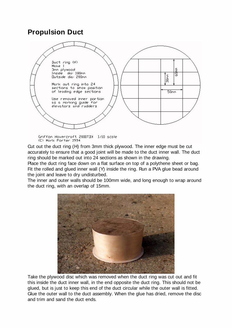
Cut out the duct ring (H) from 3mm thick plywood. The inner edge must be cut accurately to ensure that a good joint will be made to the duct inner wall. The duct ring should be marked out into 24 sections as shown in the drawing. Place the duct ring face down on a flat surface on top of a polythene sheet or bag. Fit the rolled and glued inner wall (Y) inside the ring. Run a PVA glue bead around the joint and leave to dry undisturbed. The inner and outer walls should be 100mm wide, and long enough to wrap around the duct ring, with an overlap of 15mm.
Take the plywood disc which was removed when the duct ring was cut out and fit this inside the duct inner wall, in the end opposite the duct ring. This should not be glued, but is just to keep this end of the duct circular while the outer wall is fitted. Glue the outer wall to the duct assembly. When the glue has dried, remove the disc and trim and sand the duct ends.
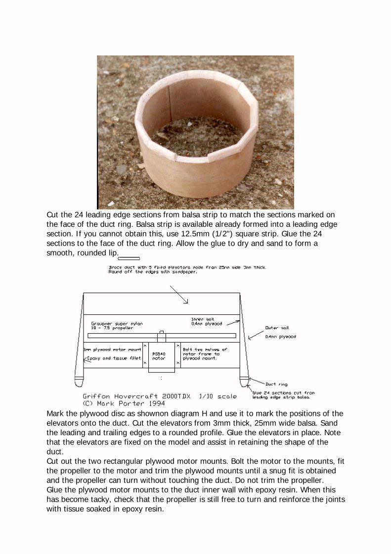
Cut the 24 leading edge sections from balsa strip to match the sections marked on the face of the duct ring. Balsa strip is available already formed into a leading edge section. If you cannot obtain this, use 12.5mm (1/2") square strip. Glue the 24 sections to the face of the duct ring. Allow the glue to dry and sand to form a smooth, rounded lip.
Mark the plywood disc as shownon diagram H and use it to mark the positions of the elevators onto the duct. Cut the elevators from 3mm thick, 25mm wide balsa. Sand the leading and trailing edges to a rounded profile. Glue the elevators in place. Note that the elevators are fixed on the model and assist in retaining the shape of the duct. Cut out the two rectangular plywood motor mounts. Bolt the motor to the mounts, fit the propeller to the motor and trim the plywood mounts until a snug fit is obtained and the propeller can turn without touching the duct. Do not trim the propeller. Glue the plywood motor mounts to the duct inner wall with epoxy resin. When this has become tacky, check that the propeller is still free to turn and reinforce the joints with tissue soaked in epoxy resin.

The rudders should be cut from 3mm thick, 60mm wide balsa. One rudder is placed vertically in the central position, and the other two are placed 50mm from the central rudder. The rudders should be cut to match the width of the duct at the point where they fit.
Making the Skirt
The skirt is made from a series of panels. The panels are stitched or glued together at the edges. The outer edge of the skirt is then attached to the outer edge of the craft. The inner edge of the skirt is attached to the base of the craft.
Making the Skirt
Skirt Panels
The following numbers of skirt panels are required. Behind each link is a skirt panel .jpg file. The skirt panels are drawn on a 10mm square grid. Print the panel drawings, and scale them so that the grid is 10mm square. Panel Quantity P1 2 P2 8 P3 2 Note that panel P3 is made from one piece P3a, one piece P3b and a 600 by 387mm straight section.

P1 P2
P3a P3b

Skirt Airflow
This diagram shows the skirt configuration. Air from the lift fan inflates the skirt, and then the air passes through the central duct and generates the air cushion.
Fitting the Skirt
The skirt is attached in two stages. The outer edge of the skirt is attached to the outer edge of the craft. The inner edge of the skirt is attached to the base of the craft. Each panel has a long edge and a short edge. The long edge is attached to the outer edge of the craft. The outer edge has an overlap, or hem. This should be folded over and glued in place. The side panel P3 is attached first. Note that panel P3 is made from panels P3a, straight section and P3b. Panel P1 at each end is fitted next. The P2 panels are then attached. The inner edges should be tacked in place and the skirt inflated as a "trial fit". The inner edges may have to be slightly repositioned for best inflation. The inner edge of panel P3 are glued along the bottom side edges of the centre box section of the craft. The end panels P1 are attached to the end edges of the box section. The remaining panels P2 fit between P1 and P3.
Machinery
Motors
The motors are based the Mabuchi or Johnson RS540 type. Graupner make a "Speed 600", which is ideal.
Propellors

The lift propeller is 6 inch (150mm) diameter, with a pitch of 3 or 4 inches (75 or 100mm). It will be marked something like "6x4" or "150x100". The thrust prop is a "180x75".
Griffon 2000TDX spec sheet
Length: 105 cm Beam: 51 cm Height: 14 cm Hull: Plywood, balsa wood and aluminium Skirt: Coated nylon Weight: 2630 g
Controls: 2 channel radio, 1 electronic speed control, 2 servo
Motors: 1 Jonhnson HC683G and 1 Graupner Speed 600
Batteries: 7.2V 1500mAh (2)