ground anchor systems
TRANSCRIPT


Using WUsing Williams Productsilliams Products
Readers of this catalog should independently verify the efficiency of any Williams products for the purpose intendedby the user. The suitability of Williams products will depend upon field conditions, fabrications and user specificationswhich must be investigated and controlled by the user or its representatives. What follows are some suggestions forproper use of Williams products.
Proper Use is the KeyProper Use is the KeyWilliams Form Engineering Corporation provides a limited warranty on all of its products, as set forth in its quota-
tions, acknowledgements and invoices furnished to each customer in connection with the sale of those products. Notwithstanding this limited warranty, you should be aware that Williams products are intended for use by qualified andexperienced workers. Serious accidents may result from misuse or improper supervision or inspection. Carefully fieldtest any use not strictly conforming to normal practice before general adoption of the application. Carefully evaluate theproduct application, determine safe working loads and control all field conditions to prevent unsafe load applications. Allsafety factors shown are approximate, and in no case should they be exceeded.
IMPROPER USE OR INSTALLATION MAY RESULT IN SERIOUS INJURY OR DEATH. IF YOU HAVE THESLIGHTEST DOUBT CONCERNING PROPER USE OR INSTALLATION, PLEASE CONSULT WITH OUR ENGI-NEERING DEPARTMENT.
YYou are Responsible for ou are Responsible for Any Modifications or SubstitutionsAny Modifications or SubstitutionsDo not weld any casting, unless in the opinion of a qualified engineer such weld is in a no load, non-critical area.
Welding causes carbides and extreme brittleness near the weld point, and destroys nearly all load value. Any weldingor modifications to Williams products are the responsibility of the user, and as set forth in its limited warranty, WilliamsForm Engineering Corporation makes no representations or warranties concerning products altered, welded, bent ormodified by others.
Many Williams products are manufactured, supplied and or designed as a system. Hence, we cannot guarantee thatcomponents from systems supplied by other manufacturers are interchangeable with our products. For best results, allparts of a system should consist of Williams products. From time to time, Williams Form Engineering Corporation maychange product designs, safe working load ratings and product dimensions without prior notice to users. For the mostcurrent information concerning Williams products, please contact our engineering department, one of our technical rep-resentative or see our web site.
Ongoing Inspection and Replacement are EssentialOngoing Inspection and Replacement are EssentialEach user should periodically inspect bolts and working hardware for wear and discard worn parts. Bent bolts, and
bolts used at loads exceeding advertised yield strength should be discarded and replaced. A comprehensive inspectionand replacement program should be instituted and followed, so that all bolts will be replaced after a predetermined num-ber of uses, regardless of the apparent condition of the bolt.
All lifting hardware units displayed in this catalog are subject to wear, misuse, overloading, corrosion, deformationand other factors which may affect their safe working load. They should be regularly inspected to see if they may beused at the rated safe working load or removed from service. Frequency of inspection is dependent upon frequency andperiod of use, environment and other factors, and is best determined by an experienced user taking into account theactual conditions under which the hardware is used.
Ordering Procedure and WOrdering Procedure and WarrantiesarrantiesThis catalog is intended to provide potential purchasers and users with general information about products offered
by Williams Form Engineering Corporation. Prices, specifications, product descriptions and catalog items are subject tomodification without prior notice. Any person desiring further information about products offered by Williams FormEngineering Corporation may contact the company or its authorized representatives. In appropriate cases, Williams willprovide quotations for possible orders.
Because the contents of this catalog are intended for general information purposes, they are subject to change with-out notice. Any warranties for Williams products shall be governed by Williams quotations, acknowledgements andinvoices furnished to customers in connection with the sale of Williams products, as these documents contain more detailthan this catalog. Williams Form Engineering Corporation disclaims all other warranties for its products, expressed orimplied, including IMPLIED WARRANTIES OF MERCHANTABILITY AND FITNESS FOR A PARTICULAR PURPOSE,which might otherwise arise from the contents of this catalog.
®
FORM ENGINEERING CORP.

Using WUsing Williams Productsilliams Products . . . . . . . . . . . . . . . . . . . . . 2TTable of Contentsable of Contents . . . . . . . . . . . . . . . . . . . . . . . . . . . 3
Chapter 1: Design ConsiderationsChapter 1: Design ConsiderationsDifferent Types of Ground Anchors . . . . . . . . . . . . . . 4Differences Between Anchor Types . . . . . . . . . . . . . 5Determining Type of Anchor Needed . . . . . . . . . 6 & 7Pre-Stressed Anchors Defined . . . . . . . . . . . . . . . . . 8Free Body Diagrams . . . . . . . . . . . . . . . . . . . . . . . . 9Determining the Length of Anchor Needed . . . 10 & 11Corrosion Protection . . . . . . . . . . . . . . . . . . . . 12 & 13
Chapter 2: Spin-Lock Mechanical Rock Chapter 2: Spin-Lock Mechanical Rock AnchorsAnchorsSpin-Lock Introduction . . . . . . . . . . . . . . . . . . . . . . 14Spin-Lock Anchor Data . . . . . . . . . . . . . . . . . . 15 - 18Spin-Lock Head Assemblies . . . . . . . . . . . . . . . . . . 19Spin-Lock Installation Procedures . . . . . . . . . . 20 - 23Spin-Lock Project Photos . . . . . . . . . . . . . . . . . . . . 23
Chapter 3: Other Mechanical Chapter 3: Other Mechanical AnchorsAnchorsSledge Drive Anchors . . . . . . . . . . . . . . . . . . . . . . . 24Bail Anchors . . . . . . . . . . . . . . . . . . . . . . . . . . . . . . 25
Chapter 4: Polyester Resin Chapter 4: Polyester Resin AnchorsAnchorsResin Anchor Introduction . . . . . . . . . . . . . . . . . . . . 26Resin Anchor Specifications . . . . . . . . . . . . . . . . . . 27Resin Anchor Installation Procedures . . . . . . . . . . . 28Resin Anchor Project Photos . . . . . . . . . . . . . . . . . . 29
Chapter 5: Cement Grout Bonded Chapter 5: Cement Grout Bonded AnchorsAnchorsMCP Anchor Introduction . . . . . . . . . . . . . . . . 30 & 31MCP Specifications . . . . . . . . . . . . . . . . . . . . . 32 & 33MCP Project Photos . . . . . . . . . . . . . . . . . . . . . . . . 34
Chapter 6: Soil NailsChapter 6: Soil NailsSoil Nail Information . . . . . . . . . . . . . . . . . . . . . . . . 35Soil Nail Specifications . . . . . . . . . . . . . . . . . . . . . . 36Soil Nail Project Photos . . . . . . . . . . . . . . . . . . . . . 37
Chapter 7: Manta Ray &Chapter 7: Manta Ray & Stingray Soil Stingray Soil AnchorsAnchorsManta Ray & Stingray Introduction . . . . . . . . . 38 & 39Manta Ray & Stingray Installation . . . . . . . . . . . . . . 40Manta Ray & Stingray Project Photos . . . . . . . . . . . 41
Chapter 8: MicropilesChapter 8: MicropilesMicropile Introduction . . . . . . . . . . . . . . . . . . . . . . . 42Micropile Project Photos . . . . . . . . . . . . . . . . . . . . . 43
Chapter 9: Self Drilling Chapter 9: Self Drilling AnchorsAnchorsSelf-Drilling Anchors . . . . . . . . . . . . . . . . . . . . 44 & 45
Chapter 10: Threaded Steel Bars & Chapter 10: Threaded Steel Bars & AccessoriesAccessories150 KSI All-Thread-Bar . . . . . . . . . . . . . . . . . . 46 & 47Grade 75 All-Thread Rebar . . . . . . . . . . . . . . . 48 & 49Other Bars and Accessories . . . . . . . . . . . . . . 50 & 51
Chapter 1Chapter 11: 1: AccessoriesAccessoriesRock Bolt Accessories . . . . . . . . . . . . . . . . . . . . . . 52 Resin & Bail Anchor Accessories . . . . . . . . . . . . . . . 53Grouting Accessories . . . . . . . . . . . . . . . . . . . . . . . 54
Chapter 12: Installation EquipmentChapter 12: Installation EquipmentGrout Pumps . . . . . . . . . . . . . . . . . . . . . . . . . . . . . 55Hydraulic Jacks . . . . . . . . . . . . . . . . . . . . . . . . . . . 56Torque Equipment . . . . . . . . . . . . . . . . . . . . . . . . . . 57Torque Tension Graphs . . . . . . . . . . . . . . . . . . 58 & 59
TTable of Contentsable of Contents
®
FORM ENGINEERING CORP.
TTechnical echnical AssistanceAssistanceLet Williams help save you thousands of dollars in start up costs by acting as an on-site advisor during your anchor
bolt installation.Our technician will work directly with your superintendent and crews to see they are prepared in terms of equipment
needs, material coordination, and efficient installation procedures to yield the best productivity possible.Our technicians are trained in most types of anchoring conditions and can often trim days off the bolting schedule by
recommending efficient procedures. Technicians may also prove to be very beneficial in consulting with the design engi-neer to propose any last minute design changes to accommodate field conditions. Even the simplest anchoring job couldhave delays for an inexperienced crew. Take advantage of our expertise and be prepared to keep your project onschedule.
*Advance notification is requested. Contact your nearest Williams Representative for fee schedules.
®
FORM ENGINEERING CORP.
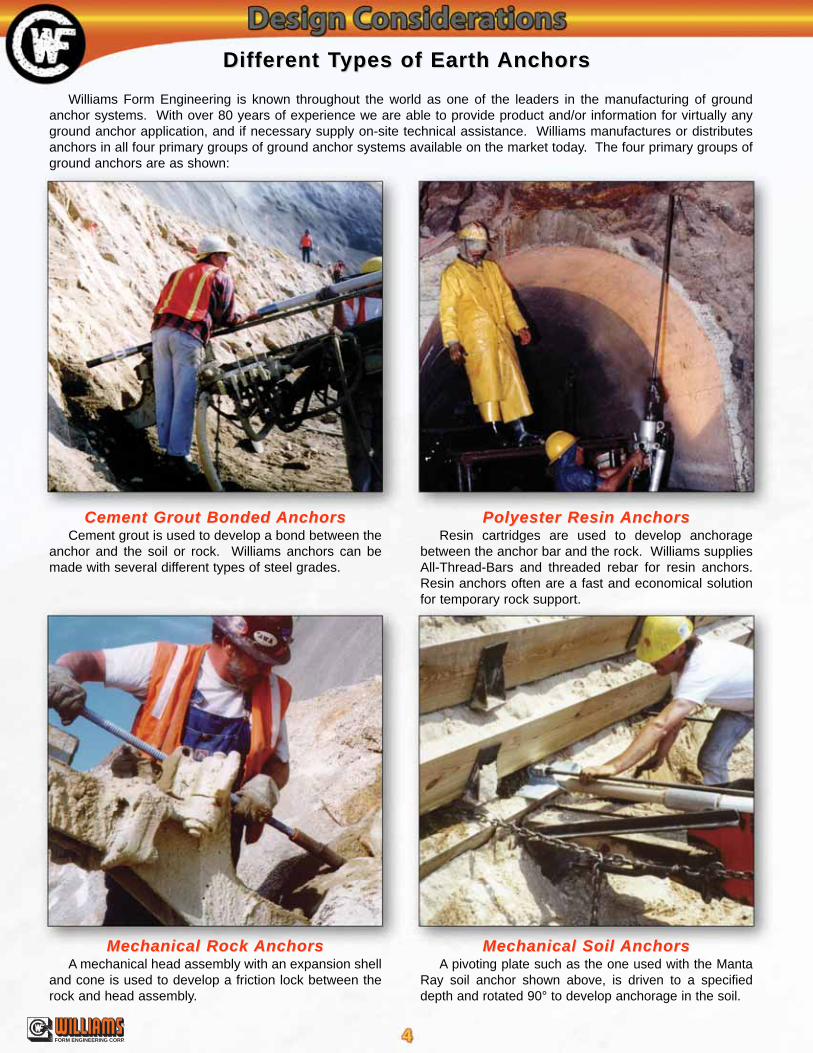
Cement Grout Bonded Cement Grout Bonded AnchorsAnchorsCement grout is used to develop a bond between the
anchor and the soil or rock. Williams anchors can bemade with several different types of steel grades.
Polyester Resin Polyester Resin AnchorsAnchorsResin cartridges are used to develop anchorage
between the anchor bar and the rock. Williams suppliesAll-Thread-Bars and threaded rebar for resin anchors.Resin anchors often are a fast and economical solutionfor temporary rock support.
Mechanical Soil Mechanical Soil AnchorsAnchorsA pivoting plate such as the one used with the Manta
Ray soil anchor shown above, is driven to a specifieddepth and rotated 90° to develop anchorage in the soil.
Mechanical Rock Mechanical Rock AnchorsAnchorsA mechanical head assembly with an expansion shell
and cone is used to develop a friction lock between therock and head assembly.
Williams Form Engineering is known throughout the world as one of the leaders in the manufacturing of groundanchor systems. With over 80 years of experience we are able to provide product and/or information for virtually anyground anchor application, and if necessary supply on-site technical assistance. Williams manufactures or distributesanchors in all four primary groups of ground anchor systems available on the market today. The four primary groups ofground anchors are as shown:
Different TDifferent Types of Earth ypes of Earth AnchorsAnchors

®
FORM ENGINEERING CORP.
Mechanical Rock Mechanical Rock AnchorsAnchors
Advantages1. Less drilling is necessary to develop the same shearcone as the bonded anchor system. Also, less grout isneeded since there is less hole volume. 2. The installer can prestress and grout the anchor in thesame day. 3. There is no cracking of the grout column, since theinstaller is prestressing the anchor before grouting. 4. The oversized drill hole provides for excellent grout cov-erage.
Disadvantages1. The mechanical rock anchor should only be used incompetent rock.2. The maximum working load for Williams largestmechanical anchor, utilizing a 2:1 safety factor from theultimate tensile steel capacity, is 180 kips.
Grout Bonded Rock & Soil Grout Bonded Rock & Soil AnchorsAnchors
Advantages1. Grout bonded anchors can be used in virtually all rockconditions and also in most soils.2. The maximum working load with a single Williams baranchorage can be as high as 480 kips (utilizing a 2:1 safe-ty factor from the ultimate tensile strength of the steel).
Disadvantages1. The installer must wait for adequate compressivestrength of the grout to be reached before prestressing theanchor.2. Deeper drilling is required to develop the design load incomparison to a mechanical anchor.3. In weak rock or soils, a test program or sample boringsshould be used to determine drill hole diameter andanchor lengths.
Polyester Resin Rock Polyester Resin Rock AnchorsAnchors
Advantages1. Prestressing can be accomplished within minutes ofthe installation.2. Resin bonded anchor bolts are one of the most eco-nomical temporary rock anchor systems available.3. Resin anchoring is successful in most rock types.
Disadvantages1. Resin anchors are difficult to protect against corrosion.They require tight drill holes for proper mixing of car-tridges, resulting in only a thin resin cover. In addition,resin anchors cannot be centered in the drill hole, whichallows the bolt to rest on the bottom or side of the hole.Resin is placed into the drill hole in a premeasuredamount which does not account for resin loss into rockseams and cracks. Loss of resin creates unprotectedgaps along the anchor, essentially reducing the safetyfactor of the system.2. Resin anchors with lengths over 25 feet are difficult toinstall because resin gel time often requires speedyinstallations. Couplings cannot be used with full columnresin anchors because their outer diameter is too largerelative to the drill hole diameter.3. Water presence can greatly reduce the holding capac-ity of the anchor or cause the anchors to be susceptibleto creep.4. Temperature affects set and cure times of the resin.
Mechanical Soil Mechanical Soil AnchorsAnchors
Advantages1. Problems associated with drilling anchor holes areeliminated because the anchor is driven into the soil.2. All anchors are tested during installation and provideimmediate anchorage. Actual holding capacity is deter-mined during pull testing.3. Time and expense associated with mixing and dis-pensing grout is eliminated.
Disadvantages1. The anchors are designed to hold no more than a 50kip maximum working load. Holding capacity can be lim-ited by the bearing strength of the soil.2. Corrosion protection is limited.3. Rocks or other obstructions in the installation path canprevent adequate embedment.
Differences Between Differences Between Anchor TAnchor Typesypes
Bonded Bonded AnchorAnchor Mechanical Mechanical AnchorAnchor

®
FORM ENGINEERING CORP.
Choosing an Choosing an Appropriate Rock Appropriate Rock AnchorAnchor
Is the full anchor length estimat-ed to be less then 75 feet?
Is the anchorpermanent?
Will the anchor be in competent rock?(RQD values and core recovery samples should be evaluated to determine rockcompetence. Often, RQD values greater than 75% and rock unconfined com-
pressive strengths greater than 2500 psi will indicate competent rock.)
Is the anchorless then 30 feet?
Can the working loadbe reduced and the number
of anchors increased?
Is corrosionprotection essential?
Is the anchorprestressed?
One possibility would be to use a High Tensile orHollow-Core Spin-Lock mechanical rock anchor.This allows for the installer to prestress and grout theanchor in the same day. Mechanical rock anchorsare shorter in length than bonded rock anchors. Thissystem also provides an excellent barrier againstcorrosion. Typically Spin-lock anchors are less than60 feet in length, however they have been installedsuccessfully over 100 feet for foundation tie downanchors. Spin-lock anchors are self-centering sothey do not require centralizers.
One option wouldbe to use grout bondGrade 75 or Grade 150All-Thread-Bar rockdowel. If corrosion pro-tection is important,epoxy coat or galvanizethe anchor system.
One possibilitywould be to use apolyester resin rockdowel utilizing aGrade 75 or Grade150 All-Thread-Bar.
One option would be touse an MCP II or III systemutilizing a Grade 75 orGrade 150 All-Thread-Bar,depending on the designload. If the ground isextremely aggressive, thedesigner may consider gal-vanizing or epoxy coatingthe bar used with the MCPsystem.
One option wouldbe a Grade 75 or 150All-Thread cementgrouted Dowel.
One option wouldbe an MCP I utilizinga Grade 75 or Grade150 All-Thread-Bardepending on theload.
Possible useof multiple baranchorages ora multi-strandanchor system.
One possibilitywould be a cementgrout bond Grade 75 orGrade 150 All-Thread-Bar epoxy coated orgalvanized. If moreprotection is desiredthe system can also beMCP protected.
One option would be apolyester resin utilizing aGrade 75 or Grade 150 All-Thread-Bar. A fast set resincan be placed in the bondzone and a slow set resin inthe free-stressing length.Another option may be touse a temporary Spin-Lockmechanical anchor, whichallows for a shorter length.
Is the anchorprestressed?
Is the anchorprestressed?
YES
NO
YES
NO
YES
Is the anchorprestressed?
NO
YES
NO
NO
YES
NOYESYES
YESNO
YES
YES YES NO
NO
NO NO YES
NO
STSTAAWill the an
rock o
ROCK
Is the anchor workingload less then 480 kips?
Is the anchor workingload greater than 180 kips?

®
FORM ENGINEERING CORP.
ARTARTnchor be inr soil?
Choosing an Choosing an Appropriate Soil Appropriate Soil AnchorAnchor
Can the load bereduced and the numberof anchors increased?
Is corrosionprotection essential?
One option would be to use an MCPII or III system utilizing a Grade 75 orGrade 150 All-Thread-Bar. WilliamsMCP systems have variable levels ofcorrosion protection depending on theaggressivity of the soil environment.
One possibility would be a grout bondedepoxy coated or galvanized Grade 75 barwith the option of MCP type protection.Another option may be to use a galvanizedManta Ray earth anchor system.
One optionwould be a Grade75 or 150 All-Thread cementgrouted dowel.
One possibility would be a Grade 75or Grade 150 All-Thread-Bar grouteddowel, either epoxy coated or galva-nized. If more protection is desired, thesystem can also be sleeved and pre-grouted as a MCP anchor system.
Most likely willneed a multiplebar anchorage ora multi-strandanchor system.
One possibility wouldbe a MCP I utilizing aGrade 75 or Grade 150All-Thread-Bar depend-ing on the anchor load.
One option would beto use a Grade 75 barwith a Manta Ray orSting Ray anchorassembly. Anotheroption would be a groutbonded Grade 75 dowel.
Is the anchorprestressed?
Is the anchorprestressed?
YES NO
YES
NO
YESNO NOYES
YES
NOYES
YES
YES
NO
Is the anchorprestressed?
Is the anchor workingload less then 480 kips?
Is the anchor workingload less than 50 kips?
Is corrosionprotection essential?
NO
NO
Notes:This flow chart is meant to be a quick reference. A designer should consider that flow charts such as this can not incorporate every vari-able relevant to the design of earth anchors. For additional help in choosing an anchor system please contact your nearest Williams repre-sentative.1. Certain rock strata may require consolidation grouting prior to rock anchor installation in order to minimize the difficulties associated with grouting
anchors in fractured rock.2. For low temperature and high impact applications, Williams can manufacture Spin-Lock anchors using ASTM A-193 grade B7 material or an ASTM
A-320 grade L7 material.3. The term MCP refers to Williams (M)ultiple (C)orrosion (P)rotection anchor systems, which are shown on pages 30-34.4. Most of Williams All-Thread Bars come in stock lengths of 50 ft. For longer anchors, Williams Stop-Type Couplings are often used for a
mechanical connection between bars. Williams couplers develop 100% of the bars ultimate strength.5. Williams can manufacture anchors using stainless steel bars if anchoring into highly aggressive rock or soil.
SOIL

®
FORM ENGINEERING CORP.
The prestressing of a rock or soil anchor is done by one of two methods. The first and most accurate way to prestress ananchor is to use a hollow ram hydraulic jack which couples directly to the end of the anchor with a pull rod assembly. The jackframe typically bears against the steel plate while the hydraulic ram transfers a direct tension load to the anchor. When the pre-stress load is reached, the anchor nut is turned tightly against the anchor bearing plate, and the load from the jack is released.The anchor nut prevents the steel from relaxing back to its original length, therefore, the anchor has been prestressed. Oncethe anchor is put into service, additional elongation in the anchor rod only occurs if the applied load exceeds the prestress load.
The second method of prestressing is to use a torque tension method. Unlike competing products, Williams full, concen-tric, rolled threads allow for torque tensioning when applicable. This is accomplished by simply turning the anchor nut againstthe anchor bearing plate with a torque wrench. By using a “torque tension relationship” provided by Williams, the installer cancorrelate the torque reading to a corresponding anchor tension load. Although not as accurate as direct tensioning, it is oftenused for fast, economical installations in areas where hydraulic jacks would be cumbersome or difficult to utilize. Torque ten-sioning is recommended to be done using a high-pressure lubricant under the hex nut to resist frictional resistance.
Prestressed earth anchors are often used for resisting cyclic or dynamic loading caused by wind or fluctuating water tables.They are also used to limit or restrict structural movement due to anchor steel elongation. Common applications for prestressedearth anchors are tower foundations, tie back walls, slope and dam stability, and tunnel bolting. Non-tensioned anchors or pas-sive dowels are often used for temporary support, resisting shear loads, static loading, or for applications with low conse-quences of failure.
Prestressed Earth Prestressed Earth AnchorsAnchors
Prestressed BoltPrestressed Bolt
With a non-tensioned dowel, anchorage starts at the surface andactually breaks down and cracks the grout as the load transfers deep-er along the length of the bolt. Over time the total anchorage may belost due to these recurring grout breakdowns.
Non-TNon-Tensioned Dowels May Produceensioned Dowels May Producethe Following Efthe Following Effects:fects:
Not Pre-Tested - Any application of load onto the bolt will cause the grout to crack in the first several inches of drill hole depth.
Floating Condition - Allows floating of foundation or uplift of thestructure due to steel elongation.
Possible Fatigue Failure - Bolt can stretch and relax as the loadvaries.
Possible Corrosion Problem - Bolt elongation will crack protectivegrout cover.
Benefits of a Prestressed Benefits of a Prestressed Anchor:Anchor:Pre-tested - By prestressing an anchor, each bolt is essentially “pre-test-ed”, assuring it will hold its design load prior to final construction.
Eliminate Fatigue Stress - Fatigue failure is minimized since the serviceload must exceed the prestressed load of the bolt to cause additional steelelongation. Therefore, the periodic stretching and relaxing that causesfatigue failure is eliminated.
Eliminate Uplift - Prestressing can eliminate a “floating” condition of afoundation due to the natural hydraulic pressures or uplift loads caused bywind or other overturning moments.
Negligible Bond Stress Relief - In cases where the earth anchor free-stress length is grouted after prestress, the grout hardens around thedeformations of the bar and bonds to the rock in the drill hole to help pre-vent stress relief in the bolt.
Corrosion Protection - A prestressed earth anchor will not elongatethrough the grout column in the free-stressing length. Elongation breaksdown and cracks the grout, opening the door to corrosion and eventual fail-ure. This is a common problem with passive or “non-tensioned” rock dow-els.
Dowel BoltDowel Bolt

®
FORM ENGINEERING CORP.
Free Body DiagramsFree Body Diagrams
These diagrams are shown to help illustrate what happens to a prestressed anchor when an external load is applied. Theexternal load must exceed the prestressed amount before affecting the original load.
11Prestress load ofPrestress load of
1000 lbs.1000 lbs.
When a prestress load isapplied and locked off, theanchorage load is equal to theforce carried by the hex nut orthe load bearing against theanchor plate.
22External load of 700 lbs.External load of 700 lbs.is applied to the anchoris applied to the anchor
When an external force isapplied to a prestressed anchor, theforce on the bearing plate is reducedby the same amount as the externalload. However, the anchor load isstill unchanged unless the externalload exceeds the prestress load.
33External load ofExternal load of
1500 lbs. is applied1500 lbs. is applied
If the external load exceedsthe prestress load, the nut is nolonger holding a load. Then theanchorage load will be the sameas the external load until anchoror rock/soil failure occurs.
1,000 lbs. 1,000 lbs. 1,500 lbs.
1,500 lbs.700 lbs.
300 lbs.1,000 lbs.
®
FORM ENGINEERING CORP.
General CommentsGeneral CommentsThe length and load capacity of rock and soil anchor systems is dependent on many variables. Some of these variables
are rock or soil properties, installation methods, underground or overhead obstructions, existing structures, right of way andeasement limitations, anchor material strength and anchor type. Topics such as these should be evaluated during an anchorfeasibility study prior to final anchor design. Final embedment depths should be determined on a project to project basis afterreviewing rock or soil samples, previous experience and geological data. On-site anchor tests are generally the best way toaccurately determine anchor lengths and capacities for the given geological conditions.
Determining Proper Determining Proper Anchor LengthAnchor Length
Free-Stress LengthFree-Stress LengthPrestressed or post-tensioned earth anchors must be designed with a free-stress length. This is the portion of the anchor
length that does not provide anchorage to the soil or rock during the stressing procedure. The purpose of the free-stresslength is to allow the installer to transfer an immediate anchor load directly to a specific location in the soil or rock. Forinstance, when designing tie back anchors, the free-stress length should be long enough to transfer the prestress load behindthe predicted failure plane of the soil or rock mass. The free-stress length also helps to minimize load loss due to movementat the anchor head during load transfer from the stressing jack. The Post Tensioning Institute recommends that for pre-stressed rock or soil anchors utilizing steel bars, the free-stress length shall be a minimum of 10 feet, and for steel strand aminimum of 15 feet due to greater seating losses. PTI recommendations on free-stress length are based on anchors utilizinghigh strength post-tension steel and often have relatively high design loads. Lighter load prestressed mechanical rock anchorshave been successfully designed and installed with overall lengths shorter than 10 feet in high quality rock.
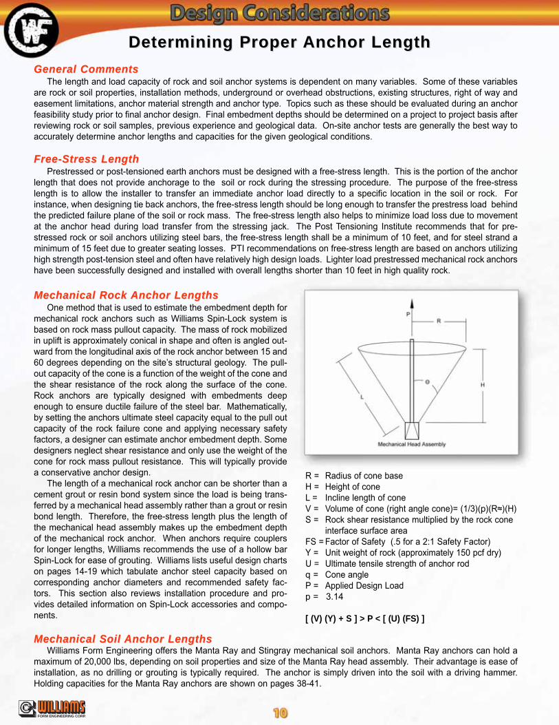
Mechanical Rock Mechanical Rock Anchor LengthsAnchor LengthsOne method that is used to estimate the embedment depth for
mechanical rock anchors such as Williams Spin-Lock system isbased on rock mass pullout capacity. The mass of rock mobilizedin uplift is approximately conical in shape and often is angled out-ward from the longitudinal axis of the rock anchor between 15 and60 degrees depending on the site’s structural geology. The pull-out capacity of the cone is a function of the weight of the cone andthe shear resistance of the rock along the surface of the cone.Rock anchors are typically designed with embedments deepenough to ensure ductile failure of the steel bar. Mathematically,by setting the anchors ultimate steel capacity equal to the pull outcapacity of the rock failure cone and applying necessary safetyfactors, a designer can estimate anchor embedment depth. Somedesigners neglect shear resistance and only use the weight of thecone for rock mass pullout resistance. This will typically providea conservative anchor design.
The length of a mechanical rock anchor can be shorter than acement grout or resin bond system since the load is being trans-ferred by a mechanical head assembly rather than a grout or resinbond length. Therefore, the free-stress length plus the length ofthe mechanical head assembly makes up the embedment depthof the mechanical rock anchor. When anchors require couplersfor longer lengths, Williams recommends the use of a hollow barSpin-Lock for ease of grouting. Williams lists useful design chartson pages 14-19 which tabulate anchor steel capacity based oncorresponding anchor diameters and recommended safety fac-tors. This section also reviews installation procedure and pro-vides detailed information on Spin-Lock accessories and compo-nents.
Mechanical Soil Mechanical Soil Anchor LengthsAnchor LengthsWilliams Form Engineering offers the Manta Ray and Stingray mechanical soil anchors. Manta Ray anchors can hold a
maximum of 20,000 lbs, depending on soil properties and size of the Manta Ray head assembly. Their advantage is ease ofinstallation, as no drilling or grouting is typically required. The anchor is simply driven into the soil with a driving hammer.Holding capacities for the Manta Ray anchors are shown on pages 38-41.
R = Radius of cone baseH = Height of cone L = Incline length of cone V = Volume of cone (right angle cone)= (1/3)(p)(R≈)(H) S = Rock shear resistance multiplied by the rock cone
interface surface areaFS = Factor of Safety (.5 for a 2:1 Safety Factor)Y = Unit weight of rock (approximately 150 pcf dry) U = Ultimate tensile strength of anchor rodq = Cone angle P = Applied Design Loadp = 3.14
[ (V) (Y) + S ] > P < [ (U) (FS) ]

®
FORM ENGINEERING CORP.
Determining Proper Determining Proper Anchor LengthAnchor LengthBonded Rock Bonded Rock Anchor LengthsAnchor Lengths
Embedment depths for prestressed resin or cement grout bonded rock anchors are often determined by using therock cone method as described under Mechanical Rock Anchor Lengths. However, unlike the mechanical anchor, thebonded anchor must also include a bond length in the embedment depth. The bond length allows the applied tensileload to be transferred to the surrounding rock. Therefore the embedment depth of a prestressed bonded rock anchor ismade up of the free-stress length and the bond length. When using the rock cone method, a conservative approachwould be to assume the pullout cone starts at the top of the bond zone. The bond length can be estimated by using thefollowing equation, however test anchors are generally the best way to determine anchor embedments and capacities.Typical values shown below are from the Post-Tensioning Institute. They are not meant to be used for final design. Finalbond stresses should be determined after the review of sample cores, previous experience and geological data.
Bonded Soil Bonded Soil Anchor LengthsAnchor LengthsEmbedments for prestressed soil anchors consist of a 10 foot minimum
free-stress length (for bar anchorages) and typically 20-40 feet of bondedlength. Anchor drilling and grouting methods can have significant impact onsoil bond stress values therefore final bond lengths are often determined byspecialty anchor contractors. Shown below is a chart that can be used to esti-mate anchor bond length. This chart is for straight shaft anchors installed insmall diameter holes using low grout pressure. However, final anchor capac-ity should be determined from field testing the anchors. For further guidanceand recommendation on the design of prestressed bonded soil and rockanchors, refer to the Post-Tensioning Institutes manual on rock and soilanchors. Also refer to AASHTO for applicable publications.
Note: Actual values for pressure grouted anchors depend on the ability to develop pressures in each type of soil.
Estimated Average Ultimate Bond Stress for Determining Soil/Grout Bond Lengths (after PTI, 1996)
P = Design load for the anchor p = 3.14 D = Diameter of the drill hole Lb = Bond length Tw = Working bond stress along theinterface between the rock and grout(The working bond stress is normally50 percent or less of the ultimate bondstress.)
Note - The ultimate bond stressbetween the rock and the anchorgrout is estimated by a value of 10%of the unconfined compressivestrength of the rock, but not more than450 psi (3.1 MPa).
Ultimate Grout/Bond StressEstimates For Various Rock
(Bond stress taken from PTI)
P(p)(D)(Tw)
Lb =
Granite and Basalt 250-450 psi
Dolomitic Limestone 200-300 psi
Soft Limestone 150-200 psi
Slated and Hard Shales 120-200 psi
Soft Shales 30-120 psi
Sandstones 120-250 psi
Concrete 200-400 psi
Cohesive Soil Cohesionless Soil
Anchor Type
Average UltimateBond Stress at
Soili/Grout Interface(psi)
Anchor Type
Average UltimateBond Stress at
Soili/Grout Interface(psi)
Gravity Grouted Anchors (straight shaft) 5-10 Gravity Grouted Anchors (straight shaft) 10-20
Pressure Grouted Anchors (straight shaft)- Soft silty clay- Silty clay- Stiff clay, medium to high plasticity- Very stiff clay, medium to hight plasticity- Stiff clay, medium plasticity- Very stiff clay, medium plasticity- Very stiff sandy silt, medium plasticity
5 - 105 - 105 - 10
10 - 2515 - 3520 - 5040 - 55
Pressure Grouted Anchors (straight shaft)- Fine-medium sand, medium dense - dense- Medium coarse sand (w/ gravel), medium dense- Medium coarse sand (w/ gravel), dense - very dense- Silty sands- Dense glacial till- Sandy gravel, medium dense - dense- Sandy gravel, dense - very dense
12 - 5516 - 95
35 - 14025 - 6043 - 75
31 - 20040 - 200
®
FORM ENGINEERING CORP.
The level of corrosion protection for an earth anchor is primarily dependent on the service life of the anchor, theaggressivity of the environment, installation methods and consequences of failure. An anchor with a service life greaterthan 24 months is generally considered permanent. Permanent anchors should always have some type of corrosion pro-tection incorporated into their design.
Ground aggressivity is generally influenced by the following:
1. Electrical resistivity of the soil (Soil is aggressive if resistance is less than 2000 ohm-cm.) 2. pH value of the soil (Soil is aggressive if less than 5.5) 3. Chemical characteristics of the ground water, rock, or soil (salt water, slag fill, industrial waste, organic fill etc.) 4. Moisture5. Presence of oxygen 6. Stray electrical currents
Grout Bonded Rock or Soil Grout Bonded Rock or Soil AnchorsAnchorsThe standard permanent grout bonded rock or soil anchor consists of an epoxy coated or galvanized anchor rod,
grouted in an oversized drill hole. Centralizers should be used to assure good grout cover (approximately 25 mm)around the bar. Additional corrosion protection may be desired if the rock or soil is considered to be aggressive, con-sequences of failure are high or anchoring into material where good grout cover is difficult to achieve. Williams MultipleCorrosion Protection (MCP) systems offer increasing barriers against corrosion attack. Williams MCP systems allow theanchor bar to be engulfed in a pre-grouted poly-corrugated tube. Protective end caps may also be used to seal the nutand washer from the environment when the outer end of the anchorage will not be encased in concrete.
Mechanical Rock Mechanical Rock AnchorsAnchorsWilliams Spin-Lock mechanical rock anchors are used when anchoring into competent rock. The standard Williams
Spin-Lock anchor relies on cement grout for corrosion protection. Williams Spin-Locks can be specified with a hollowanchor bar, allowing the system to be grouted from the lowest gravitational point in both up and down bolting applica-tions. This provides a solid grout cover surrounding the anchor rod. Unlike the bonded rock anchor, the Spin-lock isgrouted after the anchor is stressed so cracking of the grout column due to prestressing is eliminated. Spin-Lockanchors have been in service since 1959 and in most cases have relied strictly on cement grout for corrosion protec-tion. If so desired, additional corrosion protection can be provided by step drilling a larger diameter drill hole, whichprovides additional grout cover, or by galvanizing the steel anchor rod. Protective end caps may also be used to sealthe nut and washer from the environment when the outer end of the anchorage will not be encased in concrete.
Corrosion Protection Corrosion Protection
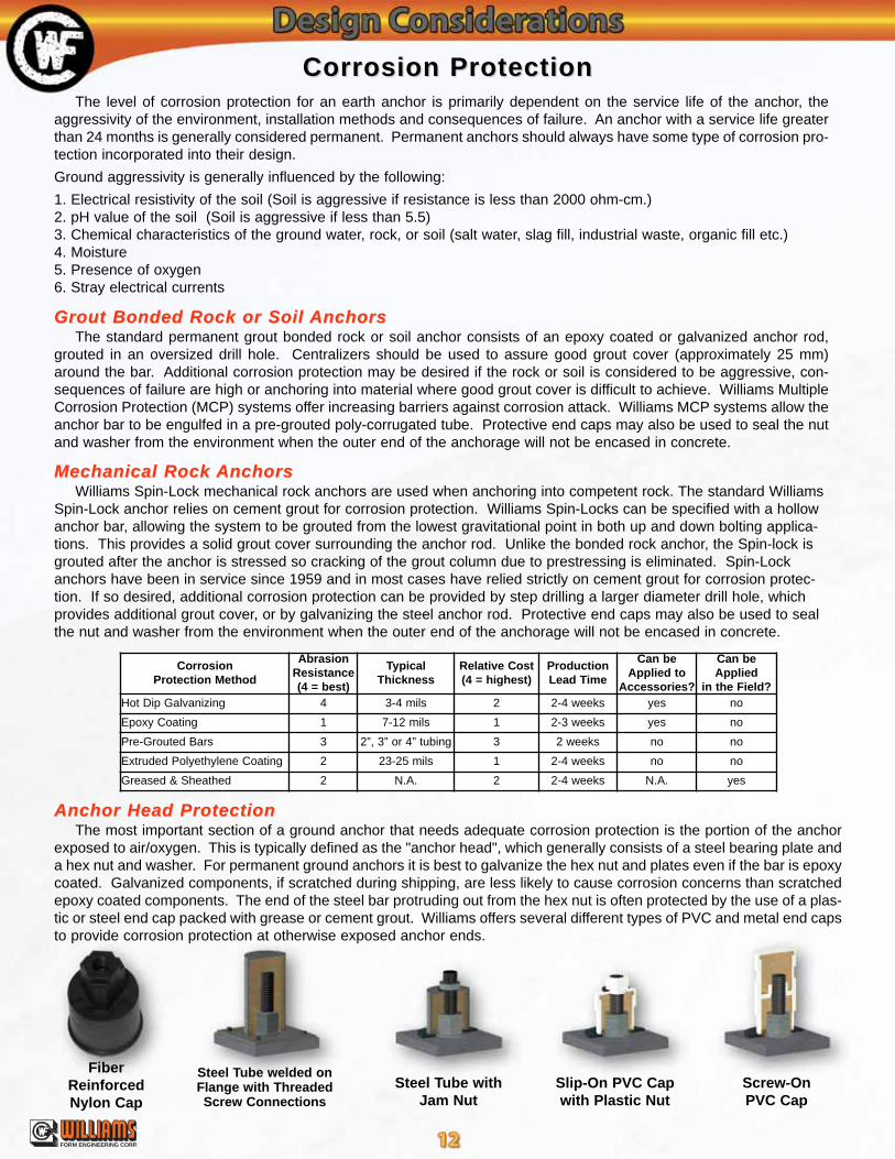
Anchor Head ProtectionAnchor Head ProtectionThe most important section of a ground anchor that needs adequate corrosion protection is the portion of the anchor
exposed to air/oxygen. This is typically defined as the "anchor head", which generally consists of a steel bearing plate anda hex nut and washer. For permanent ground anchors it is best to galvanize the hex nut and plates even if the bar is epoxycoated. Galvanized components, if scratched during shipping, are less likely to cause corrosion concerns than scratchedepoxy coated components. The end of the steel bar protruding out from the hex nut is often protected by the use of a plas-tic or steel end cap packed with grease or cement grout. Williams offers several different types of PVC and metal end capsto provide corrosion protection at otherwise exposed anchor ends.
Screw-OnPVC Cap
Slip-On PVC Capwith Plastic Nut
Steel Tube withJam Nut
Steel Tube welded onFlange with ThreadedScrew Connections
FiberReinforcedNylon Cap
CorrosionProtection Method
AbrasionResistance(4 = best)
TypicalThickness
Relative Cost(4 = highest)
ProductionLead Time
Can beApplied to
Accessories?
Can beApplied
in the Field?Hot Dip Galvanizing 4 3-4 mils 2 2-4 weeks yes no
Epoxy Coating 1 7-12 mils 1 2-3 weeks yes no
Pre-Grouted Bars 3 2”, 3” or 4” tubing 3 2 weeks no no
Extruded Polyethylene Coating 2 23-25 mils 1 2-4 weeks no no
Greased & Sheathed 2 N.A. 2 2-4 weeks N.A. yes

®
FORM ENGINEERING CORP.
Corrosion Protection Corrosion Protection
Hot Dip GalvanizingHot Dip GalvanizingZinc serves as a sacrificial metal corroding preferentially to the steel. Galvanized
bars have excellent bond characteristics to grout or concrete and do not require as muchcare in handling as epoxy coated bars. However, galvanization of anchor rods is gen-erally more expensive then epoxy coating and often has greater lead time. Hot dip gal-vanizing bars and fasteners should be done in accordance with ASTM A-153. Typicalgalvanized coating thickness for steel bars and components is between 3 and 4 mils.150 KSI high strength steel bars should always be mechanically cleaned (neveracid washed) to avoid problems associated with hydrogen embrittlement.
Epoxy CoatingEpoxy CoatingFusion bonded epoxy coating of steel bars to help prevent corrosion has been suc-
cessfully employed in many applications because of the chemical stability of epoxyresins. Epoxy coated bars and fasteners should be done in accordance with ASTM A-775. Coating thickness is generally specified between 7 to 12 mils. Epoxy coated barsand components are subject to damage if dragged on the ground or mishandled. Heavyplates and nuts are often galvanized even though the bar may be epoxy coated sincelarge heavy components are difficult to protect against abrasion in the field. Epoxy coat-ing patch kits are often used in the field for repairing nicked or scratched epoxy surfaces.
Pre-Grouted BarsPre-Grouted BarsCement Grout filled corrugated polyethylene tubing is often used to provide an addi-
tional barrier against corrosion attack in highly aggressive soils. These anchors areoften referred to as MCP or Multiple Corrosion Protection anchors. The steel bars arewrapped with an internal centralizer then placed inside of the polyethylene tube wherethey are then factory pre-grouted. When specifying couplings with MCP groundanchors, verify coupling locations with a Williams representative.
Extruded PolyethyleneExtruded PolyethyleneHigh density polyethylene is tightly bonded to the anchor bar by a flexible bituminous
mastic. This effectively helps to eliminate migration of moisture and oxygen (require-ments for corrosion). Polyethylene thickness is typically 23 to 25 mils., and can be doneon bars ranging from #6 up to Williams largest bar diameters. Anchor threaded endsmust be uncoated to allow for couplings and anchor nuts. Ends can be protected withend caps or corrosion inhibiting tape, or depending on the application, encased in con-crete. Extruded polyethylene generally requires sizable orders to be a competitive cor-rosion protection method. Coating specifications are available from Williams uponrequest.
Greased & SheathedGreased & SheathedCorrosion inhibiting grease is often specified within the
free-stress length of ground anchor systems. Often thebars are greased and PVC is slipped over the greased barprior to shipping. The grease functions as protectionagainst corrosion and the sheathing serves as a bond-breaker.
Heat Shrink THeat Shrink TubingubingHeat Shrink Tubing provides a corrosion protected
seal when connecting smooth or corrugated segments.
Corrosion Inhibiting TCorrosion Inhibiting TapeapeCorrosion Inhibiting Tape is available in 33’ rolls of 2”
and 4” widths.
Epoxy Coating Patch Kits areavailable upon request.
Epoxy Coating Patch KitEpoxy Coating Patch Kit
IntroductionIntroduction
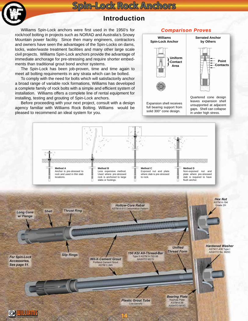
Williams Spin-Lock anchors were first used in the 1950’s forrock/roof bolting in projects such as NORAD and Australia’s SnowyMountain power facility. Since then many engineers, contractorsand owners have seen the advantages of the Spin-Locks on dams,locks, water/waste treatment facilities and many other large scalecivil projects. Williams Spin-Lock anchors provide the advantage ofimmediate anchorage for pre-stressing and require shorter embed-ments than traditional grout bond anchor systems.
The Spin-Lock has been job-proven, time and time again tomeet all bolting requirements in any strata which can be bolted.
To comply with the need for bolts which will satisfactorily anchora broad range of variable rock formations, Williams has developeda complete family of rock bolts with a simple and efficient system ofinstallation. Williams offers a complete line of rental equipment forinstalling, testing and grouting of Spin-Lock anchors.
Before proceeding with your next project, consult with a designagency familiar with Williams Rock Bolting. Williams would bepleased to recommend an ideal system for you.
Comparison ProvesComparison Proves
Method AAnchor is pre-stressed torock and used in thin slablocations.
Method BLess expensive method.Used where pre-stressedrock is anchored to largeslabs or footings.
Method CExposed nut and platewhere slab is pre-stressedto rock.
Method DNon-exposed nut andplate where pre-stressedslab is required to haveflush anchor.
Expansion shell receivesfull bearing support fromsolid 300° cone design.
Quartered cone designleaves expansion shellunsupported at adjacentgaps. Shell can collapsein under high stress.
UniformContact
Area
WilliamsSpin-Lock Anchor
Serrated Anchorby Others
PointContacts
®
FORM ENGINEERING CORP.
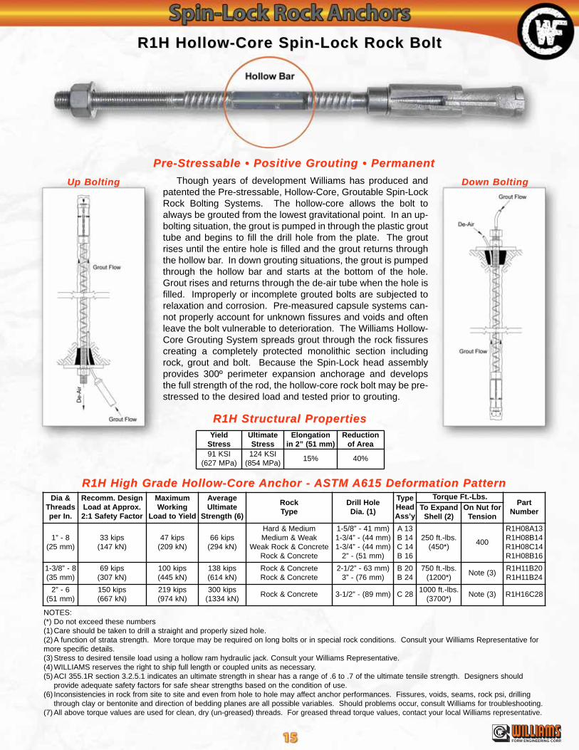
Though years of development Williams has produced andpatented the Pre-stressable, Hollow-Core, Groutable Spin-LockRock Bolting Systems. The hollow-core allows the bolt toalways be grouted from the lowest gravitational point. In an up-bolting situation, the grout is pumped in through the plastic grouttube and begins to fill the drill hole from the plate. The groutrises until the entire hole is filled and the grout returns throughthe hollow bar. In down grouting situations, the grout is pumpedthrough the hollow bar and starts at the bottom of the hole.Grout rises and returns through the de-air tube when the hole isfilled. Improperly or incomplete grouted bolts are subjected torelaxation and corrosion. Pre-measured capsule systems can-not properly account for unknown fissures and voids and oftenleave the bolt vulnerable to deterioration. The Williams Hollow-Core Grouting System spreads grout through the rock fissurescreating a completely protected monolithic section includingrock, grout and bolt. Because the Spin-Lock head assemblyprovides 300º perimeter expansion anchorage and developsthe full strength of the rod, the hollow-core rock bolt may be pre-stressed to the desired load and tested prior to grouting.
Pre-Stressable • Positive Grouting • PermanentPre-Stressable • Positive Grouting • Permanent
R1H Hollow-Core Spin-Lock Rock BoltR1H Hollow-Core Spin-Lock Rock Bolt
R1H High Grade Hollow-Core R1H High Grade Hollow-Core Anchor - Anchor - ASTM ASTM A615 Deformation PatternA615 Deformation Pattern
Up BoltingUp Bolting Down BoltingDown Bolting
R1H Structural PropertiesR1H Structural Properties
NOTES:(*) Do not exceed these numbers(1)Care should be taken to drill a straight and properly sized hole.(2)A function of strata strength. More torque may be required on long bolts or in special rock conditions. Consult your Williams Representative formore specific details.(3)Stress to desired tensile load using a hollow ram hydraulic jack. Consult your Williams Representative.(4)WILLIAMS reserves the right to ship full length or coupled units as necessary.(5)ACI 355.1R section 3.2.5.1 indicates an ultimate strength in shear has a range of .6 to .7 of the ultimate tensile strength. Designers should
provide adequate safety factors for safe shear strengths based on the condition of use.(6) Inconsistencies in rock from site to site and even from hole to hole may affect anchor performances. Fissures, voids, seams, rock psi, drilling
through clay or bentonite and direction of bedding planes are all possible variables. Should problems occur, consult Williams for troubleshooting.(7) All above torque values are used for clean, dry (un-greased) threads. For greased thread torque values, contact your local Williams representative.
YieldStress
UltimateStress
Elongationin 2” (51 mm)
Reductionof Area
91 KSI(627 MPa)
124 KSI(854 MPa)
15% 40%
Dia &Threadsper In.
Recomm. DesignLoad at Approx.2:1 Safety Factor
MaximumWorking
Load to Yield
AverageUltimate
Strength (6)
RockType
Drill HoleDia. (1)
TypeHeadAss’y
Torque Ft.-Lbs.Part
NumberTo ExpandShell (2)
On Nut forTension
1” - 8(25 mm)
33 kips(147 kN)
47 kips(209 kN)
66 kips(294 kN)
Hard & MediumMedium & Weak
Weak Rock & ConcreteRock & Concrete
1-5/8” - 41 mm)1-3/4” - (44 mm)1-3/4” - (44 mm)
2” - (51 mm)
A 13B 14C 14B 16
250 ft.-lbs.(450*)
400
R1H08A13R1H08B14R1H08C14R1H08B16
1-3/8” - 8(35 mm)
69 kips(307 kN)
100 kips(445 kN)
138 kips(614 kN)
Rock & ConcreteRock & Concrete
2-1/2” - 63 mm)3” - (76 mm)
B 20B 24
750 ft.-lbs.(1200*)
Note (3)R1H11B20R1H11B24
2” - 6(51 mm)
150 kips(667 kN)
219 kips(974 kN)
300 kips(1334 kN)
Rock & Concrete 3-1/2” - (89 mm) C 281000 ft.-lbs.
(3700*)Note (3) R1H16C28
®
FORM ENGINEERING CORP.
NOTES:(*) Do not exceed these numbers(1)Care should be taken to drill a straight and properly sized hole.(2)A function of strata strength. More torque may be required on long bolts or in special rock conditions. Consult your Williams Representative formore specific details.(3)Stress to desired tensile load using a hollow ram hydraulic jack. Consult your Williams Representative.(4)WILLIAMS reserves the right to ship full length or coupled units as necessary.(5)ACI 355.1R section 3.2.5.1 indicates an ultimate strength in shear has a range of .6 to .7 of the ultimate tensile strength. Designers should
provide adequate safety factors for safe shear strengths based on the condition of use.(6) Inconsistencies in rock from site to site and even from hole to hole may affect anchor performances. Fissures, voids, seams, rock psi, drilling
through clay or bentonite and direction of bedding planes are all possible variables. Should problems occur, consult Williams for troubleshooting.(7) All above torque values are used for clean, dry (un-greased) threads. For greased thread torque values, contact your local Williams representative.
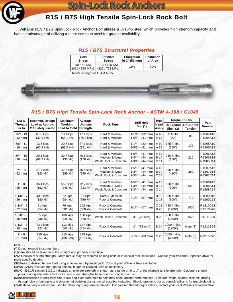
R1S / B7S High TR1S / B7S High Tensile Spin-Lock Rock Boltensile Spin-Lock Rock Bolt
Williams R1S / B7S Spin-Lock Rock Anchor Bolt utilizes a C-1045 steel which provides high strength capacity andhas the advantage of utilizing a more common steel for greater availability.
R1S / B7S Structural PropertiesR1S / B7S Structural Properties
R1S / B7S High TR1S / B7S High Tensile Spin-Lock Rock ensile Spin-Lock Rock Anchor - Anchor - ASTM ASTM A-108 / C1045A-108 / C1045
Meets strength of ASTM A325
YieldStress
UltimateStress
Elongationin 2” (51 mm)
Reductionof Area
90 / 81 KSI(621 / 558 MPa)
120 / 105 KSI(827 / 723 MPa)
11% 20%
Dia &Threadsper In.
Recomm. DesignLoad at Approx.2:1 Safety Factor
MaximumWorking
Load to Yield
AverageUltimateStrength
Rock TypeDrill HoleDia. (1)
TypeHeadAss’y
Torque Ft.-Lbs.Part
NumberTo ExpandShell (2)
On Nut forTension
1/2” - 13(12 mm)
8.53 kips(37.9 kN)
13.1 kips(58.1 kN)
17.1 kips(75.8 kN)
Hard & MediumHard & Medium
1-1/4” - (32 mm)1-5/8” - (41 mm)
A 10A 13
50 ft.-lbs.(70*)
85R1S04A10R1S04A13
5/8” - 11(16 mm)
13.6 kips(60.3 kN)
20.8 kips(92.5 kN)
27.1 kips(121 kN)
Hard & MediumHard & Medium
1-1/4” - (32 mm)1-5/8” - (41 mm)
A 10A 13
125 ft.-lbs.(250*)
125R1S05A10R1S05A13
3/4” - 10(20 mm)
20.1 kips(89.2 kN)
30.7 kips(137 kN)
40.1 kips(178 kN)
Hard & MediumMedium & Weak
Weak Rock & Concrete
1-5/8” - (41 mm)1-3/4” - (44 mm)1-3/4” - (44 mm)
A 13B 14C 14
210 ft.-lbs.(250*)
210R1S06A13R1S06B14R1S06C14
7/8” - 9(22 mm)
27.7 kips(123 kN)
42.5 kips(189 kN)
55.4 kips(246 kN)
Hard & MediumMedium & Weak
Weak Rock & Concrete
1-5/8” - (41 mm)1-3/4” - (44 mm)1-3/4” - (44 mm)
A 13B 14C 14
390 ft.-lbs.(410*)
390R1S07A13 R1S07B14R1S07C14
1” - 8(25 mm)
36.4 kips(162 kN)
55.8 kips(248 kN)
72.7 kips(323 kN)
Hard & MediumMedium & Weak
Weak Rock & Concrete
1-5/8” - (41 mm)1-3/4” - (44 mm)1-3/4” - (44 mm)
A 13B 14C 14
500 ft.-lbs.(600*)
550R1S08A13R1S08B14R1S08C14
1-1/8” - 7(29 mm)
40.5 kips(180 kN)
62 kips(284 kN)
81 kips(360 kN)
Hard & MediiumRock & Concrete
2-1/4” - (57 mm)B 16C 18
550 ft.-lbs.(600*)
770R1S09B16R1S09C18
1-1/4” - 7(32 mm)
51 kips(254 kN)
79 kips(381 kN)
102 kips(508 kN)
Rock & ConcreteRock & Concrete
2-1/4” - (57 mm)C 18B 20
750 ft.-lbs.(1200*)
1000R1S10C18R1S10B20
1-3/8” - 8(35 mm)
65 kips(289 kN)
100 kips(445 kN)
130 kips(578 kN)
Weak Rock & Concrete 3” - (76 mm) B 20750 ft.-lbs.
(1600*)1525 R1S11B20
1-1/2” - 6(38 mm)
73.5 kips(327 kN)
113 kips(503 kN)
147 kips(654 kN)
Rock & Concrete 3” - (76 mm) B 241000 ft.-lbs.
(1700*)Note (3) R1S12B24
2” - 6(51 mm)
139 kips(657 kN)
215 kips(1080 kN)
279 kips(1313 kN)
Rock & Concrete 3-1/2” - (89 mm) C 281000 ft.-lbs.
(4000*)Note (3) R1S16C28
®
FORM ENGINEERING CORP.

NOTES:(*) Do not exceed these numbers(1)Care should be taken to drill a straight and properly sized hole.(2)A function of strata strength. More torque may be required on long bolts or in special rock conditions. Consult your Williams Representative formore specific details.(3)Stress to desired tensile load using a hollow ram hydraulic jack. Consult your Williams Representative.(4)WILLIAMS reserves the right to ship full length or coupled units as necessary.(5)ACI 355.1R section 3.2.5.1 indicates an ultimate strength in shear has a range of .6 to .7 of the ultimate tensile strength. Designers should
provide adequate safety factors for safe shear strengths based on the condition of use.(6) Inconsistencies in rock from site to site and even from hole to hole may affect anchor performances. Fissures, voids, seams, rock psi, drilling
through clay or bentonite and direction of bedding planes are all possible variables. Should problems occur, consult Williams for troubleshooting.(7) All above torque values are used for clean, dry (un-greased) threads. For greased thread torque values, contact your local Williams representative.
R1JR1J Solid Rebar Spin-Lock Rock BoltSolid Rebar Spin-Lock Rock Bolt
The R1J uses an ASTM Grade 60 material for the anchor bolt which is generally less expensive than other Spin-Lockanchors which incorporate higher strength steels.
R1J Structural PropertiesR1J Structural Properties
R1J Solid Rebar Spin-Lock Rock R1J Solid Rebar Spin-Lock Rock Anchor - Anchor - ASTM ASTM A-615A-615
Dia &Threadsper In.
Recomm. DesignLoad at Approx.2:1 Safety Factor
MaximumWorking
Load to Yield
AverageUltimateStrength
Rock TypeDrill HoleDia. (1)
TypeHeadAss’y
Torque Ft.-Lbs.Part
NumberTo ExpandShell (2)
On Nut forTension
1/2” - 13(12 mm)
6.35 kips(28.2 kN)
8.5 kips(37.7 kN)
12.7 kips(56.5 kN)
Hard & MediumHard & Medium
1-1/4” - (32 mm)1-5/8” - (41 mm)
A 10A 13
50 ft.-lbs.(50*)
60R1J04A10R1J04A13
5/8” - 11(16 mm)
10.2 kips(45.2 kN)
13.5 kips(60.1 kN)
20.3 kips(90.3 kN)
Hard & MediumHard & Medium
1-1/4” - (32 mm)1-5/8” - (41 mm)
A 10A 13
100 ft.-lbs.(100*)
110R1J05A10R1J05A13
3/4” - 10(20 mm)
15 kips(66.7 kN)
20 kips(88.9 kN)
30 kips(134 kN)
Hard & MediumMedium & Weak
Weak Rock & Concrete
1-5/8” - (41 mm)1-3/4” - (44 mm)1-3/4” - (44 mm)
A 13B 14C 14
165 ft.-lbs.(165*)
175R1J06A13R1J06B14R1J06C14
7/8” - 9(22 mm)
20.7 kips(92.1 kN)
27 kips(120 kN)
41.5 kips(185 kN)
Hard & MediumMedium & Weak
Weak Rock & Concrete
1-5/8” - (41 mm)1-3/4” - (44 mm)1-3/4” - (44 mm)
A 13B 14C 14
265 ft.-lbs.(265*)
290R1J07A13R1J07B14 R1J07C14
1” - 8(25 mm)
27 kips(120 kN)
36 kips(160 kN)
54 kips(240 kN)
Hard & MediumMedium & Weak
Weak Rock & Concrete
1-5/8” - (41 mm)1-3/4” - (44 mm)1-3/4” - (44 mm)
A 13B 14C 14
400 ft.-lbs.(400*)
420R1J08A13R1J08B14R1J08C14
1-1/8” - 7(29 mm)
34 kips(151 kN)
45 kips(200 kN)
68 kips(303 kN)
Hard & MediiumRock & Concrete
2-1/4” - (57 mm)B 16C 18
450 ft.-lbs.(550*)
610R1J09B16R1J09C18
1-1/4” - 7(32 mm)
43.5 kips(194 kN)
58 kips(258 kN)
87 kips(387 kN)
Rock & Concrete 2-1/4” - (57 mm) C 18750 ft.-lbs.
(750*)810 R1J10C18
1-3/8” - 8(35 mm)
55 kips(245 kN)
73 kips(325 kN)
110 kips(489 kN)
Weak Rock & Concrete 3” - (76 mm) B 20750 ft.-lbs.
(1000*)Note (3) R1J11B24
1-3/4” - 6(38 mm)
85.5 kips(380 kN)
114 kips(507 kN)
171 kips(761 kN)
Rock & Concrete 3” - (76 mm) B 241000 ft.-lbs.
(1700*)Note (3) R1J14B24
2” - 6(51 mm)
119 kips(529 kN)
159 kips(707 kN)
238 kips(1058 kN)
Rock & Concrete 3-1/2” - (89 mm) C 281000 ft.-lbs.
(4000*)Note (3) R1J16C28
YieldStress
UltimateStress
Elongationin 8” (203 mm)
60 KSI(413 MPa)
90 KSI(621 MPa)
7-9%
®
FORM ENGINEERING CORP.
Dia &Threadsper In.
Recomm. DesignLoad at Approx.2:1 Safety Factor
MaximumWorking
Load to Yield
AverageUltimateStrength
Rock TypeDrill HoleDia. (1)
TypeHeadAss’y
Torque Ft.-Lbs.Part
NumberTo ExpandShell (2)
On Nut forTension
1” - 8(25 mm)
45 kips(200 kN)
72 kips(320 kN)
90 kips(400 kN)
Rock & Concrete1-3/4”
(44 mm)C 14
500 ft.-lbs.(650*)
680 R7S08C14
1-1/4” - 7(32 mm)
72.5 kips(322 kN)
116 kips(516 kN)
145 kips(649 kN)
Rock & Concrete2-1/2”
(57 mm)B 20
750 ft.-lbs.(1200*)
1350 R7S10B20
1-1/2” - 6(38 mm)
105 kips(467 kN)
168 kips(747 kN)
210 kips(932 kN)
Rock & Concrete3”
(76 mm)B 24
1000 ft.-lbs.(1700*)
Note (3) R7S12B24
1-7/8” - 8(48 mm)
180 kips(799 kN)
289 kips(1284 kN)
360 kips(1598 kN)
Rock & Concrete3-1/2”
(89 mm)C 28
1000 ft.-lbs.(3400*)
Note (3) R7S15C28
YieldStress
UltimateStress
Elongationin 20 Bar Dia.
Reductionof Area
Charpy at-20º F (-29º C)
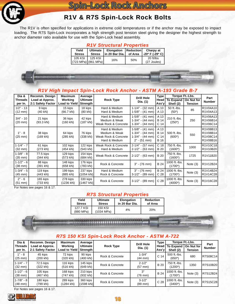
105 KSI(723 MPa)
125 KSI(861 MPa)
16% 50%20 ft/lbs
(27 Joules)
YieldStress
UltimateStress
Elongationin 20 Bar Dia.
Reductionof Area
127.7 KSI(880 MPa)
150 KSI(1034 MPa)
4% 20%
Dia &Threadsper In.
Recomm. DesignLoad at Approx.2:1 Safety Factor
MaximumWorking
Load to Yield
AverageUltimateStrength
Rock TypeDrill HoleDia. (1)
TypeHeadAss’y
Torque Ft.-Lbs.Part
NumberTo ExpandShell (2)
On Nut forTension
1/2” - 13(12 mm)
9 kips(40 kN)
15 kips(66.7 kN)
18 kips(80 kN)
Hard & MediumHard & Medium
1-1/4” - (32 mm)1-5/8” - (41 mm)
A 10A 13
50 ft.-lbs.(50*)
85R1V04A10R1V04A13
3/4” - 10(20 mm)
21 kips(93.3 kN)
36 kips(160 kN)
42 kips(187 kN)
Hard & MediumMedium & Weak
Weak Rock & Concrete
1-5/8” - (41 mm)1-3/4” - (44 mm)1-3/4” - (44 mm)
A 13B 14C 14
210 ft.-lbs.(250*)
250R1V06A13 R1V06B14 R1V06C14
1” - 8(25 mm)
38 kips(169 kN)
64 kips(285 kN)
76 kips(338 kN)
Hard & MediumMedium & Weak
Weak Rock & ConcreteHard & Medium
1-5/8” - (41 mm)1-3/4” - (44 mm)1-3/4” - (44 mm)
2” - (51 mm)
A 13B 14C 14B 16
500 ft.-lbs.(600*)
550
R1V08B13R1V08B14R1V08C14R1V08B16
1-1/4” - 7(32 mm)
61 kips(273 kN)
102 kips(454 kN)
122 kips(543 kN)
Weak Rock & ConcreteHard & Medium
2-1/4” - (57 mm)2-1/2” - (63 mm)
C 18B 20
750 ft.-lbs.(1600*)
1000R1V10C18R1V10B20
1-3/8” - 8(35 mm)
77.5 kips(344 kN)
129 kips(573 kN)
154 kips(684 kN)
Weak Rock & Concrete 2-1/2” - (63 mm) B 20750 ft.-lbs.
(1600*)1725 R1V11B20
1-1/2” - 6(38 mm)
88 kips(391 kN)
148 kips(658 kN)
176 kips(783 kN)
Rock & Concrete 3” - (76 mm) B 241000 ft.-lbs.
(1700*)Note (3) R1V12B24
1-3/4” - 5(45 mm)
119 kips(443 kN)
199 kips(885 kN)
237 kips(1054 kN)
Hard & MediumRock & Concrete
3” - (76 mm)3-1/2” - (89 mm)
B 24C 28
1000 ft.-lbs.(1700*)
Note (3)R1V14B24R1V14C28
2” - 6(51 mm)
165 kips(733 kN)
278 kips(1236 kN)
330 kips(1467 kN)
Rock & Concrete 3-1/2” - (89 mm) C 281000 ft.-lbs.
(4000*)Note (3) R1V16C28
R1V & R7S Spin-Lock Rock BoltsR1V & R7S Spin-Lock Rock Bolts
The R1V is often specified for applications in extreme cold temperatures or if the anchor may be exposed to impactloading. The R7S Spin-Lock incorporates a high strength post tension steel giving the designer the highest strength toanchor diameter ratio available for use with the Spin-Lock head assembly.
R1V Structural PropertiesR1V Structural Properties
R1V High Impact Spin-Lock Rock R1V High Impact Spin-Lock Rock Anchor - Anchor - ASTM ASTM A-193 Grade B-7A-193 Grade B-7
R7S Structural PropertiesR7S Structural Properties
R7S 150 KSI Spin-Lock Rock R7S 150 KSI Spin-Lock Rock Anchor - Anchor - ASTM ASTM A-722A-722
For Notes see pages 16 & 17.
For Notes see pages 16 & 17.
®
FORM ENGINEERING CORP.
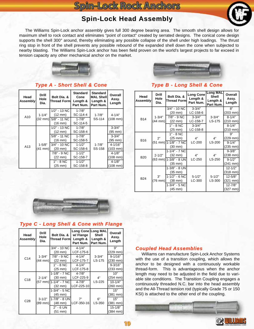
Spin-Lock Head Spin-Lock Head AssemblyAssembly
The Williams Spin-Lock anchor assembly gives full 300 degree bearing area. The smooth shell design allows formaximum shell to rock contact and eliminates “point of contact” created by serrated designs. The conical cone designsupports the shell 300° around, thereby eliminating any possible collapse of the shell under high loadings. The thrustring stop in front of the shell prevents any possible rebound of the expanded shell down the cone when subjected tonearby blasting. The Williams Spin-Lock anchor has been field proven on the world’s largest projects to far exceed intension capacity any other mechanical anchor on the market.
TType ype AA - Short Shell & Cone- Short Shell & Cone TType B - Long Shell & Coneype B - Long Shell & Cone
TType C - Long Shell & Cone with Flangeype C - Long Shell & Cone with Flange
Coupled Head Coupled Head AssembliesAssembliesWilliams can manufacture Spin-Lock Anchor Systems
with the use of a transition coupling, which allows theanchor to be designed with a continuously workablethread-form. This is advantageous when the anchorlength may need to be adjusted in the field due to vari-able site conditions. The Transition Coupling engages acontinuously threaded N.C. bar into the head assemblyand the All-Thread tension rod (typically Grade 75 or 150KSI) is attached to the other end of the coupling.
HeadAssembly
DrillHoleDia.
Bolt Dia. &Thread Form
Long ConeLength &Part Num.
Long MALShell
Length &Part Num.
OverallAssy.
Length
B141-3/4”
(44 mm)
3/4” - 10 NC(20 mm)
3-3/4”LC-158-6
3-3/4”LS-175
8”(203 mm)
7/8” - 9 NC(22 mm)
3-3/4”LC-158-7
8-1/4”(210 mm)
1” - 8 NC(25 mm)
3-3/4”LC-158-8
8-1/4”(210 mm)
B162”
(51 mm)
1” - 8 NC(25 mm) 4”
LC-2004”
LS-200
9”(229 mm)
1-1/8” - 7 NC(30 mm)
9-1/4”(235 mm)
B202-1/2”
(63 mm)
1-1/4” - 7 NC(32 mm) 4”
LC-2504”
LS-250
9-3/8”(238 mm)
1-3/8” - 8 UN(35 mm)
9-1/2”(241 mm)
B243”
(76 mm)
1-3/8” - 8 UN(35 mm)
5-1/2”LC-300
5-1/2”LS-300
12-1/2”(318 mm)
1-1/2” - 6 NC(38 mm)
12-5/8”(321 mm)
1-3/4” - 5 NC(45 mm)
12-7/8”(327 mm)
HeadAssembly
DrillHoleDia.
Bolt Dia. &Thread Form
Long Conew/ FlangeLength &Part Num.
Long MALShell
Length &Part Num.
OverallAssy.
Length
C141-3/4”
(44 mm)
3/4” - 10 NC(20 mm)
4-1/4”LCF-175-6
3-3/4”LS-175
9”(229 mm)
7/8” - 9 NC(22 mm)
4-1/4”LCF-175-7
9-1/16”(230 mm)
1” - 8 NC(25 mm)
4-1/4”LCF-175-8
9-3/16”(233 mm)
C182-1/4”
(57 mm)
1-1/8” - 7 NC(30 mm)
4-7/8”LCF-225-9 4”
LS-225
10”(254 mm)
1-1/4” - 7 NC(32 mm)
4-7/8”LCF-225-10
10-1/4”(260 mm)
C283-1/2”
(89 mm)
1-3/4” - 5 NC(45 mm)
7”LCF-350-16
6”LS-350
15”(381 mm)
1-7/8” - 8 UN(48 mm)
15”(381 mm)
2” - 6 UN(51 mm)
15-1/8”(384 mm)
HeadAssembly
DrillHoleDia.
Bolt Dia. &Thread Form
StandardCone
Length &Part Num.
StandardMAL ShellLength &Part Num.
OverallAssy.
Length
A101-1/4”
(32 mm)
1/2” - 13 NC(12 mm)
1-7/8”SC-114-4 1-7/8”
SS-1144-1/4”
(108 mm)5/8” - 11 NC(16 mm)
1-7/8”SC-114-5
A131-5/8”
(41 mm)
1/2” - 13 NC(12 mm)
1-7/8”SC-158-4
1-7/8”SS-158
3-3/4”(95 mm)
5/8” - 11 NC(16 mm)
1-7/8”SC-158-5
3-3/4”(95 mm)
3/4” - 10 NC(20 mm)
1-1/2”SC-158-6
4-1/16”(103 mm)
7/8” - 9 NC(22 mm)
1-1/2”SC-158-7
4-1/8”(108 mm)
1” - 8 NC(25 mm)
1-1/2”SC-158-8
4-1/8”(108 mm)
®
FORM ENGINEERING CORP.

Spin-Lock InstallationSpin-Lock Installation
Place the nut, washer, bevel washers (ifrequired), and plate on the rock bolt andpush the bolt into the hole to the correctembedment depth. If the bolt becomesstuck in the hole, attach a setting tool to theend of the bolt and drive it into the hole witha sledgehammer.
Step 1: DrillingStep 1: DrillingUse Standard Rotary
Percussion Equipment
Care should be taken to insurean accurate diameter and astraight hole. The depth shouldbe over drilled to allow any debristo fall to the bottom of the holewhen the anchor is inserted.Clean the drill hole by blowing airto the full depth to remove debris.Efforts should be made to preparethe collar area with a flat surfaceand as perpendicular to the boltaxis as possible.
Step 2: Bolt PlacementStep 2: Bolt Placement
Down BoltingSituationsRequireDrillingHoles 10” to16” Beyondthe Lengthof the RockBolt.
DrillHole
Rock
Hollow-CoreRock Bolt
Rock Boltbeing insertedinto Hole Grout Hole
Thrust Ring
Slip Ring
Cone
MalleableShell
HeavyDuty
Hex Nut
Setting Tool
Steel Plate
Install setting tool fully onto theexposed threaded end. Provide spacebetween the setting tool and the hex nut.Initially torque the bolt to the requiredtorque with an impact gun, pneumatic, orhydraulic torque wrench. This actionmigrates the cone into the shell, thusexpanding the mechanical anchor into therock. Final torque can be checked andadjusted with a manual or hydraulic torquewrench. Remove the setting tool byrestraining the lower part while rotating it'supper section until the setting tool is loose.Prepare collar area with Williams Wil-Kwik-Set fast setting grout to ensure fullbearing under the plate.
Step 3: Setting the Step 3: Setting the AnchorAnchor
SettingTool
Deep Socket forImpact Tool orTorque Wrench
2” - 3” ofThread
Collar Area
®
FORM ENGINEERING CORP.

Place plate, bevel washers (if required), hardened washer, and hex nut on the rock bolt. Tension the bolt by torquingthe hex nut with a torque wrench. For the recommended torque valveto obtain the advertised tensile working load, see the "Torque On Nut"column on the Spin-Lock Bolt charts listed on pages 15-18. For otherloads, see the torque tension graphs shown on pages 58 & 59.Please Note: The torque/tension relationship is not as accurate asdirect tensioning with a hydraulic jack and should not be used wherecritical tension loads need to be verified.
Spin-Lock InstallationSpin-Lock Installation
Place the jack andframe over the bolt andattach the test rod andcouplings to the bolt.Attach the test nut andtest plate over the testrod on top of the jack.Test the rock bolt bytensioning the jack tothe required test load(usually half of the ulti-mate strength) butnever to exceed the advertised yield strength of the anchor. Adjustthe loading of the jack to the required final tension and lock in thefinal pre-stress load. This is done by tightening the rock bolt hexnut with a knocker wrench (through the frame opening) until a slightreduction is noticed on the jack gauge. The full pre-stress load willbe transferred to the anchor bolt once the tension in the test jackhas been released and test components removed.
Step 4a: TStep 4a: Testingestingthe the Anchor BoltAnchor Bolt
Method A: Tensioningwith a Test Jack
Hydraulic Jack &Frame Assembly
Optional:Dial IndicatorGauge forElongationMeasurement
Wil-Kwik-SetFast Setting
Grout (Sealer)
Step 4b: TStep 4b: Testing the esting the Anchor BoltAnchor BoltMethod B: Testing by Torque Tensioning
De-Air
Deep Socketfor Impact Tool
or Torque Wrench
Test PlateTest Nut
Test Rod
Test Coupling
Hex Nut(Tighten with wrenchafter final loading)
Note: Knocker Wrenchnot shown for clarity
Wil-Kwik-SetFast Setting
Grout (Sealer)
Torque Hex Nut
®
FORM ENGINEERING CORP.

Spin-Lock InstallationSpin-Lock Installation
Always grout from the lowestgravitation point on the anchor boltuntil a steady stream of pure groutis seen coming out around thebearing plate or grout tube, and/orfrom the de-air tube. For solidbolts, this means that a separategrout tube must be placed in thedrill hole (through an opening inthe bearing plate) as deep as pos-sible before grouting. Long lengthsolid bolts should have the grouttube attached to the bolt beforeinserting and setting the anchor.Down-grouting of Hollow CoreRock Bolts can be simply groutedthrough the hollow core by attach-ing a grout tube adapter to theouter end of the tensioned boltand grouting. When the groutingis complete, all air and standingwater has been removed from thedrill hole by displacement and allcracks and voids in the anchorarea are filled with cement grout.
Up BoltingUp Bolting
Step 5: Grouting the Step 5: Grouting the AnchorAnchor
From Grout Pump
Grout Tube
Grout Tube Adapter
De-Air Tube
Wil-Kwik-Set
Williams offers a field installation advising service to aid contractors inthe initial installation process of installing all types of anchor bolts. Williams“Spin-Lock Anchor Installation Video” is also available upon request.Contact your Williams sales representative for details.
Up-grouting of Hollow-CoreRock Bolts can be done bygrouting through a short lengthgrout tube extending just pastthe drill hole sealer in the collararea thus using the hollow coreat the end of the rock bolt to de-air the hole. Up-grouting ofsolid rock bolts involves attach-ing a long length grout tube tothe anchor (prior to insertion,setting, and tensioning) andgrouting through a separateshort length tube that extendspast the sealer area thus allow-ing the rock bolt to de-air fromthe longer grout tube.
From Grout Pump
Return
Wil-Kwik-Set or DenseExpansive Foam
Down BoltingDown Bolting
Hollow-CoreRock Bolt
Shown
Hollow-CoreRock Bolt
Shown
De-Air
Grout Flow
®
FORM ENGINEERING CORP.

Spin-Lock Spin-Lock Anchor Project PhotosAnchor Project Photos
Project: Slope StabilizationProject: Slope StabilizationContractor: Contractor: YYenter Companiesenter CompaniesLocation: Cheeseman ReservoirLocation: Cheeseman Reservoir, CO, CO
Project: Central Pump StationProject: Central Pump StationContractor: WContractor: W.L. Haley.L. HaleyLocation: Nashville, TNLocation: Nashville, TN
Project: NORAD - Cheyenne Mountain Project: NORAD - Cheyenne Mountain Air StationAir StationContractor: Utah Construction &Contractor: Utah Construction & Mining CompanyMining CompanyLocation: Cheyenne Mountain, COLocation: Cheyenne Mountain, CO
Project: 1Project: 11 Mile Reservoir1 Mile ReservoirContractor: Contractor: YYenter Companiesenter CompaniesLocation: DenverLocation: Denver, CO, CO
Project: Nantahala DamProject: Nantahala DamContractor: Boyles BrothersContractor: Boyles BrothersLocation: Location: Ashville, NCAshville, NC
Project: LRProject: LRT Minn-St. Paul T Minn-St. Paul AirportAirportContractor: Obayashi / Johnson Brothers JVContractor: Obayashi / Johnson Brothers JVLocation: Minneapolis, MNLocation: Minneapolis, MN
®
FORM ENGINEERING CORP.

Sledge Drive Sledge Drive AnchorsAnchors
Quick, simple anchor designed to develop the full strength of the bar. Recommended for short anchors in rock orconcrete. Available with 1-5/8” diamenter aluminum expansion shell. In temporary situations, bar may be removed andused again. Williams can supply custom length steel drive pipes at your request.
Sledge Drive Sledge Drive Anchor InstallationAnchor Installation
Drill hole to prescribeddiameter and exactembedment depth forrock bolt.
Insert Sledge DriveAnchor to bottom of hole.Bolt may be tapped inplace.
Place heavy wall pipedriver over bar and driveshell down over cone toexpand anchor.
Attach item to beanchored or plate andnut. Anchor may be pre-stressed or pre-tested.
WWith B
1S Smooth Rod
ith B
1S Smooth Rod
WWith B
7S
ith B
7S
All-Thread C
oil Rod
All-Thread C
oil Rod
WWith R
61 Grade 75
ith R
61 Grade 75
All-Thread R
ebar
All-Thread R
ebar
SteeType
BarDiameter
Recommended SafeWorking Load to 2:1
Safety Factor
AverageUltimateStrength
DrillHole
Part NumberB8S Cone / Shell
(B7S Cone / Shell)
B1S Smooth Rod
B7S All-Thread CoilRod
B8S All-Thread N.C.Rod
3/8"(10 mm)
4.9 kips(21.8 kN)
9.8 kips(43.6 kN)
1-5/8"(41 mm)
R4M03RB0 / R4A13(R4MC3RB0 / R4A13)
1/2"(12 mm)
9 kips(40.0 kN)
18 kips(80.1 kN)
1-5/8"(41 mm)
R4M04RB0 / R4A13(R4MC4RB0 / R4A13)
5/8"(16 mm)
11.3 kips(40.0 kN)
22.5 kips(100 kN)
1-5/8"(41 mm)
R4M05RB0 / R4A13(R4MC5RB0 / R4A13)
3/4"(20 mm)
18 kips(80.0 kN)
36 kips(160 kN)
1-5/8"(41 mm)
R4M06RAC / R4A13(R4MC6RAC / R4A13)
7/8"(22 mm)
29 kips(129 kN)
58 kips(258 kN)
1-5/8"(41 mm)
R4M07RAC / R4A13(R4MC7RAC / R4A13)
R51 Grade 60
#4 - 1/2"(12 mm)
9 kips(40 kN)
18 kips(80.1 kN)
1-5/8"(41 mm)
R4MG4RAC / R4A13
#5 - 5/8"(16 mm)
13.8 kips(62 kN)
27.9 kips(124 kN)
1-5/8"(41 mm)
R4MG5RAC / R4A13
R61 Grade 75#6 - 3/4"(20 mm)
22 kips(97.9 Kn)
44 kips(196 kN)
1-5/8"(41 mm)
R4MG6RAC / R4A13
®
FORM ENGINEERING CORP.

Bail Bail AnchorsAnchors
Bail Anchors are fast setting mechanical anchors that are simple to use for light to moderate loads in temporary orpermanent applications. They set in a one step torque tension operation and work well with Williams Grade 75 All-Thread Rebar, constant torque nuts and domed plates/spherical washer assemblies. They are well suited for use in sin-gle or twin grout tube installations due to the minimal rotation the bar undergoes during the setting process.
Bail Bail Anchor InstallationAnchor InstallationBail anchors are initially set in the hole using relatively
low torques that should not exceed 30 to 50 ft/lbs. Highersetting torques applied to the bail anchor alone will not helpin the setting process. Final set of the Bail Anchor isaccomplished through direct tension with a hydraulic jackor preferably by torquing the nut against the plate. Thisaction pulls the cone further into the shell locking it intoplace. The outward migration of the bar is usually no morethan 1” to 2" maximum. This movement must be anticipat-ed and allowed for in the design and application of thisanchor type in ungrouted conditions. Bail anchor installa-tions are tested and grouted by normal methods.
For Bail Anchor Bars and Accessories, see pages 46-53.Project: St. Margret 3Project: St. Margret 3Contractor: EBCContractor: EBCLocation: Sept Iles, QuebecLocation: Sept Iles, Quebec
R5M-16R5M-16R5M-14R5M-14R5M-1R5M-111R5M-10R5M-10
Range of Bar Diameter HoleDiameter
UltimateCapacity
ShellLength
WedgeLength
BlankPart NumberUNC / Coil Grade 75
1/2" - 5/8"(13-16 mm)
N.A.1-1/4"
(32 mm)15-22.5 kips(67-100 kN)
2-1/8"(54 mm)
1-3/4"(44 mm)
R5M-F3F
1/2" - 3/4"(13-20 mm)
N.A.1-3/8"
(35 mm)15-38 kips
(67-169 kN)2-7/8"
(73 mm)1-3/8"
(35 mm)R5M-F2B
3/4" - 1"(20-25 mm)
#6, #7(20-22 mm)
1-3/4"(45 mm)
33-60 kips(147-267 kN)
3-1/4"(83 mm)
2-1/4"(57 mm)
R5M-F9F
5/8" - 1-1/8"(16-28 mm)
#6, #7, #8(20-25 mm)
2"(51 mm)
15-79 kips(67-351 kN)
4"(102 mm)
3-7/8"(98 mm)
R5M-D20
®
FORM ENGINEERING CORP.
®
FORM ENGINEERING CORP.
This chart is intended as a guide for on site trials whichwill establish the working specifications in the actualground conditions.
Drill Hole Fill ChartDrill Hole Fill Chart
Polyester Resin Polyester Resin AnchorsAnchors
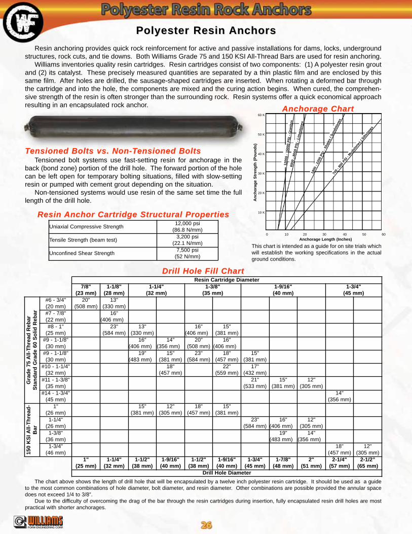
Resin anchoring provides quick rock reinforcement for active and passive installations for dams, locks, undergroundstructures, rock cuts, and tie downs. Both Williams Grade 75 and 150 KSI All-Thread Bars are used for resin anchoring.
Williams inventories quality resin cartridges. Resin cartridges consist of two components: (1) A polyester resin groutand (2) its catalyst. These precisely measured quantities are separated by a thin plastic film and are enclosed by thissame film. After holes are drilled, the sausage-shaped cartridges are inserted. When rotating a deformed bar throughthe cartridge and into the hole, the components are mixed and the curing action begins. When cured, the comprehen-sive strength of the resin is often stronger than the surrounding rock. Resin systems offer a quick economical approachresulting in an encapsulated rock anchor.
TTensioned Bolts vs. Non-Tensioned Bolts vs. Non-Tensioned Boltsensioned BoltsTensioned bolt systems use fast-setting resin for anchorage in the
back (bond zone) portion of the drill hole. The forward portion of the holecan be left open for temporary bolting situations, filled with slow-settingresin or pumped with cement grout depending on the situation.
Non-tensioned systems would use resin of the same set time the fulllength of the drill hole.
Anchorage ChartAnchorage Chart
0 10 20 30 40 50 60
An
cho
rag
e S
tren
gth
(P
ou
nd
s)
60 K
50 K
40 K
30 K
20 K
10 K
Anchorage Length (Inches)
700
- 800
PSI -
Mud
ston
es /
Siltst
ones
1800
- 2
200
PS
I - S
hale
s / S
ands
tone
s
6000
- 8
000
PS
I -
Lim
esto
nes
1200
0 -
1500
0 P
SI
- G
ran
ites
Resin Resin Anchor Cartridge Structural PropertiesAnchor Cartridge Structural Properties
Resin Cartridge Diameter7/8"
(23 mm)1-1/8"
(28 mm)1-1/4"
(32 mm)1-3/8"
(35 mm)1-9/16"(40 mm)
1-3/4"(45 mm)
20"(508 mm)
13"(330 mm)
16"(406 mm)
23"(584 mm)
13"(330 mm)
16"(406 mm)
15"(381 mm)
16"(406 mm)
14"(356 mm)
20"(508 mm)
16"(406 mm)
19"(483 mm)
15"(381 mm)
23"(584 mm)
18"(457 mm)
15"(381 mm)
18"(457 mm)
22"(559 mm)
17"(432 mm)
21"(533 mm)
15"(381 mm)
12"(305 mm)
14"(356 mm)
15"(381 mm)
12"(305 mm)
18"(457 mm)
15"(381 mm)
23"(584 mm)
16"(406 mm)
12"(305 mm)
19"(483 mm)
14"(356 mm)
18"(457 mm)
12"(305 mm)
1"(25 mm)
1-1/4"(32 mm)
1-1/2"(38 mm)
1-9/16"(40 mm)
1-1/2"(38 mm)
1-9/16"(40 mm)
1-3/4"(45 mm)
1-7/8"(48 mm)
2"(51 mm)
2-1/4"(57 mm)
2-1/2”(65 mm)
Drill Hole Diameter
Gra
de
75 A
ll-T
hre
ad R
ebar
Sta
nd
ard
Gra
de
60 S
olid
Reb
ar
#6 - 3/4"(20 mm)#7 - 7/8"(22 mm)#8 - 1"
(25 mm)#9 - 1-1/8"(30 mm)
#9 - 1-1/8"(30 mm)
#10 - 1-1/4"(32 mm)
#11 - 1-3/8"(35 mm)
#14 - 1-3/4"(45 mm)
150
KS
I All-
Th
read
-B
ar
1"(26 mm)
1-1/4"(26 mm)
1-3/8"(36 mm)
1-3/4"(46 mm)
The chart above shows the length of drill hole that will be encapsulated by a twelve inch polyester resin cartridge. It should be used as a guideto the most common combinations of hole diameter, bolt diameter, and resin diameter. Other combinations are possible provided the annular spacedoes not exceed 1/4 to 3/8”.
Due to the difficulty of overcoming the drag of the bar through the resin cartridges during insertion, fully encapsulated resin drill holes are mostpractical with shorter anchorages.
Uniaxial Compressive Strength12,000 psi
(86.8 N/mm)
Tensile Strength (beam test)3,200 psi
(22.1 N/mm)
Unconfined Shear Strength7,500 psi
(52 N/mm)

®
FORM ENGINEERING CORP.
Polyester Resin Polyester Resin AnchorsAnchors

®
FORM ENGINEERING CORP.
Polyester Resin Polyester Resin Anchor InstallationAnchor Installation
Two gel times areoffered for varied condi-tions. The standard 2-4minute gel time meetsmost requirements.However, for special con-ditions, where installa-tions are difficult or fulllength anchored ten-sioned bolts are used, a15-30 minute gel time isavailable. Gel times arestandardized at 55-60º F.The effect of temperatureon gel time is shown onthe left. Temperaturesbelow 35º F will signifi-cantly slow down settimes. Call your WilliamsRepresentative for specialfast set resins.
Gel TGel Timeime
90% of Compressive Strengthshould be reached in 6 times geltime at 75ºF.
Compressive Strength
35 45 55 65 75 85 95
38
32
28
24
20
16
12
8
4
Temperature °F
Gel
Tim
e in
Min
ute
s
StorageStorageFor maximum shelf life, cartridges should be stored
away from direct sunlight in a reasonably cool, well venti-lated dry area. Storage life is up to one year if stored at 60-80º F. Under adverse conditions, shelf life is reduced. Toinsure proper storage, the product should not be subjectedto temperatures in excess of 85º F for prolonged periods.Storage is recommended under-cover on original palletswith adequate ventilation. If stored in trailers in hot weath-er, doors should be left ajar or a sun screen erected overthe trailer. Conversely, while cold storage does notadversely effect the shelf life, cartridges should be warmedto a range of 50-60º F before using to assure gel timeswithin the specified range (see Gel Time chart). Casesshould be stacked preferably six high with a maximumnever to exceed nine cases. Over-stacking will crushcases, resulting in ruptured cartridges.
Step 1Step 1For Pre-Tensioned bolts, insert the necessary resin car-
tridges into the drill hole, by placing the fast-setting car-tridges in first and the slow-setting cartridges last. Do notallow cartridges to free fall to bottom of hole.
Step 2Step 2Push bolt into hole (rotating at this time is optional).
When bolt is completely inserted into the hole, rotate 40-60revolutions (approximately 10-15 seconds). Cautionshould be taken to avoid under-spinning or over-spinning.
Step 3Step 3Install bearing plate, washer and hex nut. Complete
pre-tensioning before slow-setting cartridges gel by using ahydraulic jack or torque wrench depending on designrequirements. Installation is complete when slow-settingresin has hardened. Special accessories used for boltangle adjustment are shown on page 53.
Step 1Step 1 Step 2Step 2 Step 3Step 3
15-30 Minute Resin
2-4 Minute Resin
Caution & SafetyCaution & SafetyThis product is intended for industrial use only. Avoid
contact with eyes and prolonged contact with skin. Wearsafety glasses when handling or installing. If contactoccurs, wash eyes or skin with water for 15 minutes. Incase of eye contact, obtain medical attention. Cartridgescontain benzoyl peroxide, polyester resin, styrene andinert fillers. The relationship between hole dimensions,bolt size and the size and number of cartridges is criticalto good performance. Your Williams representative willbe glad to assist in determining the proper combinationsfor specific applications.
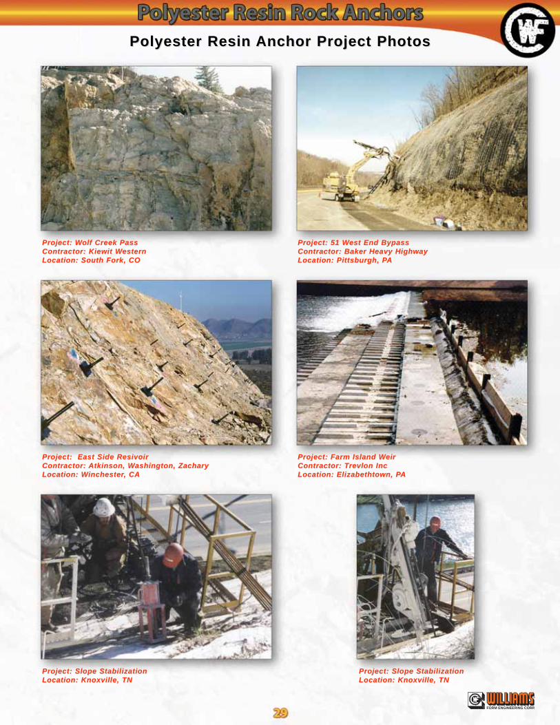
®
FORM ENGINEERING CORP.
Project: WProject: Wolf Creek Passolf Creek PassContractor: Kiewit WContractor: Kiewit WesternesternLocation: South Fork, COLocation: South Fork, CO
Project: East Side ResivoirProject: East Side ResivoirContractor: Contractor: Atkinson, WAtkinson, Washington, Zacharyashington, ZacharyLocation: WLocation: Winchesterinchester, CA, CA
Project: Slope StabilizationProject: Slope StabilizationLocation: Knoxville, TNLocation: Knoxville, TN
Project: Slope StabilizationProject: Slope StabilizationLocation: Knoxville, TNLocation: Knoxville, TN
Project: Farm Island WProject: Farm Island WeireirContractor: TContractor: Trevlon Increvlon IncLocation: Elizabethtown, PLocation: Elizabethtown, PAA
Project: 51 WProject: 51 West End Bypassest End BypassContractor: Baker Heavy HighwayContractor: Baker Heavy HighwayLocation: Pittsburgh, PLocation: Pittsburgh, PAA
Polyester Resin Polyester Resin Anchor Project PhotosAnchor Project Photos
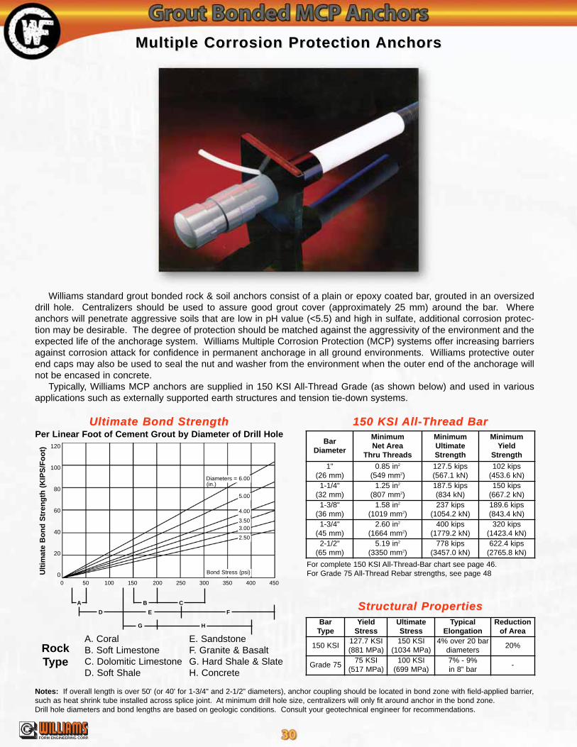
®
FORM ENGINEERING CORP.
A. CoralB. Soft LimestoneC. Dolomitic LimestoneD. Soft Shale
E. SandstoneF. Granite & BasaltG. Hard Shale & SlateH. Concrete
RockType
Ultimate Bond StrengthUltimate Bond StrengthPer Linear Foot of Cement Grout by Diameter of Drill Hole
A
0 50 100 150 200 250 300 350 400 450
120
100
80
60
40
20
0Ult
imat
e B
on
d S
tren
gth
(K
IPS
/Fo
ot)
Diameters = 6.00
4.00
3.503.00
2.50
5.00
(in.)
Bond Stress (psi)
Structural PropertiesStructural Properties
150 KSI 150 KSI All-Thread BarAll-Thread Bar
Multiple Corrosion Protection Multiple Corrosion Protection AnchorsAnchors
For complete 150 KSI All-Thread-Bar chart see page 46.For Grade 75 All-Thread Rebar strengths, see page 48
B C
ED
G H
F
Williams standard grout bonded rock & soil anchors consist of a plain or epoxy coated bar, grouted in an oversizeddrill hole. Centralizers should be used to assure good grout cover (approximately 25 mm) around the bar. Whereanchors will penetrate aggressive soils that are low in pH value (<5.5) and high in sulfate, additional corrosion protec-tion may be desirable. The degree of protection should be matched against the aggressivity of the environment and theexpected life of the anchorage system. Williams Multiple Corrosion Protection (MCP) systems offer increasing barriersagainst corrosion attack for confidence in permanent anchorage in all ground environments. Williams protective outerend caps may also be used to seal the nut and washer from the environment when the outer end of the anchorage willnot be encased in concrete.
Typically, Williams MCP anchors are supplied in 150 KSI All-Thread Grade (as shown below) and used in variousapplications such as externally supported earth structures and tension tie-down systems.
Notes: If overall length is over 50' (or 40' for 1-3/4" and 2-1/2” diameters), anchor coupling should be located in bond zone with field-applied barrier,such as heat shrink tube installed across splice joint. At minimum drill hole size, centralizers will only fit around anchor in the bond zone.Drill hole diameters and bond lengths are based on geologic conditions. Consult your geotechnical engineer for recommendations.
BarDiameter
MinimumNet Area
Thru Threads
MinimumUltimateStrength
MinimumYield
Strength
1"(26 mm)
0.85 in2
(549 mm2)127.5 kips(567.1 kN)
102 kips(453.6 kN)
1-1/4"(32 mm)
1.25 in2
(807 mm2)187.5 kips(834 kN)
150 kips(667.2 kN)
1-3/8"(36 mm)
1.58 in2
(1019 mm2)237 kips
(1054.2 kN)189.6 kips(843.4 kN)
1-3/4"(45 mm)
2.60 in2
(1664 mm2)400 kips
(1779.2 kN)320 kips
(1423.4 kN)2-1/2"
(65 mm)5.19 in2
(3350 mm2)778 kips
(3457.0 kN)622.4 kips
(2765.8 kN)
BarType
YieldStress
UltimateStress
TypicalElongation
Reductionof Area
150 KSI127.7 KSI(881 MPa)
150 KSI(1034 MPa)
4% over 20 bardiameters
20%
Grade 7575 KSI
(517 MPa)100 KSI
(699 MPa)7% - 9%in 8” bar
-

®
FORM ENGINEERING CORP.
Three barriers around plain bar in free-stress zone, two barriers in bond zone, plus drill hole grout.• Bar engulfed in pre-grouted poly corrugated tube in the bond anchorage zone and the free-stressing zone.• Smooth PVC sleeve over the corrugated tube in the free-stressing zone• Unit is centered in drill hole by centralizer and surrounded by grout• Galvanized plate• Protective end cap over nut and washer
Two barriers around plain bar full length plus drill hole grout.• Bar engulfed in pre-grouted poly corrugated tube in the bond anchorage zone• Smooth PVC sleeve over bar in free-stressing zone• Grease or grout filled smooth PVC sleeve over bar in the free stress zone• Unit is centered in drill hole by centralizers and surrounded by grout
Two barriers around plain bar in free-stress zone plus drill hole grout.• Plain, galvanized or epoxy coated bar• Smooth PVC sleeve over bar in free-stressing zone• Grease or grout filled smooth PVC sleeve over bar in the free-stress zone• Unit is centered in drill hole grout with centralizers
MCPMCP I - Class 2 Protection I - Class 2 Protection (per PTI)
Multiple Corrosion Protection Multiple Corrosion Protection AnchorsAnchorsShown with 150 KSI All-Thread Bar
Note: Drill hole diameters and bond lengths are based on geological conditions. Consult your geotechnical engineer for recommendations.
Free-Stressing ZoneFree-Stressing Zone Bond ZoneBond Zone
Free-Stressing ZoneFree-Stressing Zone Bond ZoneBond Zone
Free-Stressing ZoneFree-Stressing Zone Bond ZoneBond Zone
MCPMCP II - Class 1 Protection II - Class 1 Protection (per PTI)
MCPMCP III - Class 1 Protection III - Class 1 Protection (per PTI)
BarDiameter
Minimum DrillHole Diameter
Common Drill HoleDiameter Range
1"(26 mm)
3-1/2”(89 mm)
3-1/2” to 5”(89 to 127 mm)
1-1/4"(32 mm)
3-1/2”(89 mm)
3-1/2” to 5”(89 to 127 mm)
1-3/8"(36 mm)
4”(102 mm)
4” to 6”(102 to 152 mm)
1-3/4"(45 mm)
4-1/2”(114 mm)
4-1/2” to 7”(114 to 178 mm)
2-1/2"(65 mm)
5”(127 mm)
5” to 8”(127 to 203 mm)
BarDiameter
Minimum DrillHole Diameter
Common Drill HoleDiameter Range
1"(26 mm)
4-1/2”(114 mm)
4-1/2” to 6”(114 to 152 mm)
1-1/4"(32 mm)
4-1/2”(114 mm)
4-1/2” to 6”(114 to 152 mm)
1-3/8"(36 mm)
4-1/2”(114 mm)
4-1/2” to 6”(114 to 152 mm)
1-3/4"(45 mm)
7”(178 mm)
7” to 8”(178 to 203 mm)
2-1/2"(65 mm)
8”(204 mm)
8” to 10”(203 to 254 mm)

®
FORM ENGINEERING CORP.
Grout Bonded Multiple Corrosion Protection Grout Bonded Multiple Corrosion Protection AnchorsAnchors
DowelDowel MCPMCP II

®
FORM ENGINEERING CORP.
Grout Bonded Multiple Corrosion Protection Grout Bonded Multiple Corrosion Protection AnchorsAnchors
MCPMCP IIII MCPMCP IIIIII
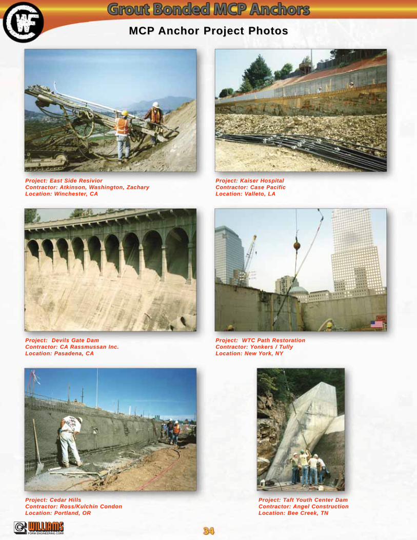
®
FORM ENGINEERING CORP.
Project: East Side ResiviorProject: East Side ResiviorContractor: Contractor: Atkinson, WAtkinson, Washington, Zacharyashington, ZacharyLocation: WLocation: Winchesterinchester, CA, CA
Project: Devils Gate DamProject: Devils Gate DamContractor: CAContractor: CA Rassmussan Inc.Rassmussan Inc.Location: Pasadena, CALocation: Pasadena, CA
Project: Cedar HillsProject: Cedar HillsContractor: Ross/Kulchin CondonContractor: Ross/Kulchin CondonLocation: Portland, ORLocation: Portland, OR
MCPMCP Anchor Project PhotosAnchor Project Photos
Project: TProject: Taft aft YYouth Center Damouth Center DamContractor: Contractor: Angel ConstructionAngel ConstructionLocation: Bee Creek, TNLocation: Bee Creek, TN
Project: Kaiser HospitalProject: Kaiser HospitalContractor: Case PacificContractor: Case PacificLocation: VLocation: Valleto, LAalleto, LA
Project: WTC Path RestorationProject: WTC Path RestorationContractor: Contractor: YYonkers / Tonkers / TullyullyLocation: New Location: New YYork, NYork, NY
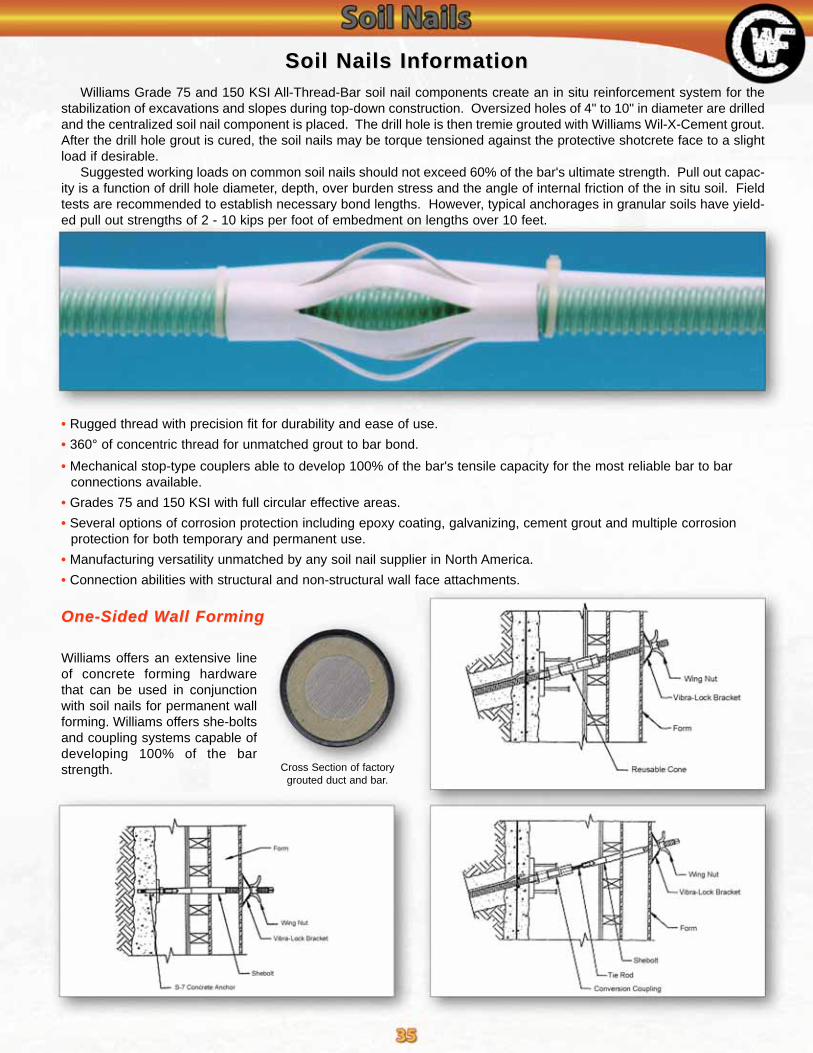
®
FORM ENGINEERING CORP.
• Rugged thread with precision fit for durability and ease of use.
• 360° of concentric thread for unmatched grout to bar bond.
• Mechanical stop-type couplers able to develop 100% of the bar's tensile capacity for the most reliable bar to bar connections available.
• Grades 75 and 150 KSI with full circular effective areas.
• Several options of corrosion protection including epoxy coating, galvanizing, cement grout and multiple corrosionprotection for both temporary and permanent use.
• Manufacturing versatility unmatched by any soil nail supplier in North America.
• Connection abilities with structural and non-structural wall face attachments.
Williams Grade 75 and 150 KSI All-Thread-Bar soil nail components create an in situ reinforcement system for thestabilization of excavations and slopes during top-down construction. Oversized holes of 4" to 10" in diameter are drilledand the centralized soil nail component is placed. The drill hole is then tremie grouted with Williams Wil-X-Cement grout.After the drill hole grout is cured, the soil nails may be torque tensioned against the protective shotcrete face to a slightload if desirable.
Suggested working loads on common soil nails should not exceed 60% of the bar's ultimate strength. Pull out capac-ity is a function of drill hole diameter, depth, over burden stress and the angle of internal friction of the in situ soil. Fieldtests are recommended to establish necessary bond lengths. However, typical anchorages in granular soils have yield-ed pull out strengths of 2 - 10 kips per foot of embedment on lengths over 10 feet.
Cross Section of factorygrouted duct and bar.
Soil Nails InformationSoil Nails Information
Williams offers an extensive lineof concrete forming hardwarethat can be used in conjunctionwith soil nails for permanent wallforming. Williams offers she-boltsand coupling systems capable ofdeveloping 100% of the barstrength.
One-Sided WOne-Sided Wall Formingall Forming

Soil Nail SpecificationsSoil Nail Specifications
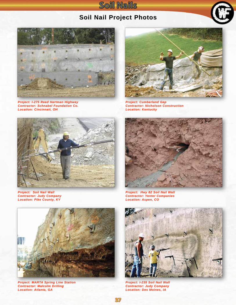
Project: I-275 Reed Hartman HighwayProject: I-275 Reed Hartman HighwayContractor: Schnabel Foundation Co.Contractor: Schnabel Foundation Co.Location: Cincinnati, OHLocation: Cincinnati, OH
Project: Soil Nail WProject: Soil Nail WallallContractor: Judy CompanyContractor: Judy CompanyLocation: Pike CountyLocation: Pike County, KY, KY
Project: MARProject: MARTTAA Spring Line StationSpring Line StationContractor: Malcolm DrillingContractor: Malcolm DrillingLocation: Location: Atlanta, GAAtlanta, GA
Soil Nail Project PhotosSoil Nail Project Photos
Project: I-235 Soil Nail WProject: I-235 Soil Nail WallallContractor: Judy CompanyContractor: Judy CompanyLocation: Des Moines, IALocation: Des Moines, IA
Project: Cumberland GapProject: Cumberland GapContractor: Nicholson ConstructionContractor: Nicholson ConstructionLocation: KentuckyLocation: Kentucky
Project: Hwy 82 Soil Nail WProject: Hwy 82 Soil Nail WallallContractor: Contractor: YYenter Companiesenter CompaniesLocation: Location: Aspen, COAspen, CO

®
FORM ENGINEERING CORP.
Manta Ray and Stingray earth anchors are driven tipping plate soil anchors for reactionof tensile loads. Manta Ray anchors have working loads up to 20 kips, and Stingray anchorshave working loads up to 50 kips. After driving the anchor to the required depth, the drivingtool (called drive steel) is removed. The anchor is then tipped and proof tested with WilliamsAnchor Locking Kit from its edgewise-driving position to present its bearing area to the soil.This is called "load locking" and provides an immediate proof test of each anchor.
Mechanical Soil Mechanical Soil AnchorsAnchors
There are eight Manta Ray Anchors andthree Stingray Anchors with light to heavyduty holding capacities. Shown to the left aresix different Manta Ray anchor heads. Allanchors are made of galvanized ductile iron,can be driven with the drive steel set (exceptthe MR-88 & M-68) and can be tested to thedesired holding capacity with the load locker.
The anchors are designed to utilize solidsteel rods as load carrying members.
MR-SRMR-SR
Manta Ray &Manta Ray & Stingray Stingray Anchor Structural PropertiesAnchor Structural Properties
Williams Anchor Rods are fully threaded and can be field cut and coupled.**Anchor rod lengths: R61-06 & R61-09 - Up to 50 feet uncoated
B8S-04 - Up to 20 feetRecommended: Galvanized rods should be cut to size prior to galvanizing to insure good nut fit.
MR-1MR-1 MR-2MR-2
MR-3MR-3 MR-4MR-4 MR-88MR-88
Manta Ray and Stingray anchors offer many significant advantages:• Fast, easy installation• Immediate proof test results• No grout• Inexpensive installation equipment• Environmentally friendly• No drilling required• Superior Holding Capacity• Anchors for a wide range of soils & applications
Stingray Stingray AnchorAnchor
Anchor Structural SafetyFactor 2:1
Recommended Anchor Rod Weightper
EachDiameter **Working Load
to YieldPart
NumberManta Ray
MR-682.5 kips(11 kN)
1/2”(12 mm)
13 kips(57.8 kN)
B8S-041 lbs.
(0.45 kg)
MR-885 kips
(22 kN)1/2”
(12 mm)13 kips
(57.8 kN)B8S-04
2.2 lbs.(1 kg)
MR-48.5 kips(36 kN)
3/4”(20 mm)
33 kips(147 kN)
R61-064.7 lbs.(2.1 kg)
MR-310 kips(45 kN)
3/4”(20 mm)
33 kips(147 kN)
R61-066 lbs.
(2.7 kg)
MR-220 kips(89 kN)
3/4”(20 mm)
33 kips(147 kN)
R61-0610 lbs.(4.5 kg)
MR-120 kips(89 kN)
3/4”(20 mm)
33 kips(147 kN)
R61-0612 lbs.
(5..4 kg)
MR-SR20 kips(89 kN)
3/4”(20 mm)
33 kips(147 kN)
R61-0621 lbs.(9.5 kg)
MK-B20 kips(89 kN)
3/4”(20 mm)
33 kips(147 kN)
R61-0685 lbs.
(38.5 kg)Sting Ray S.F. Diameter ** Working Load Part Number Weight
SR-145.5 kips(198 kN)
1-1/8”(28 mm)
75 kips(334 kN)
R61-0947 lbs.
(21.3 kg)
SR-250 kips
(223 kN)1-1/8”
(28 mm)75 kips
(334 kN)R61-09
66 lbs.(30 kg)
SR-350 kips
(223 kN)1-1/8”
(28 mm)75 kips
(334 kN)R61-09
91 lbs.(41.2 kg)

®
FORM ENGINEERING CORP.
Manta Ray Holding Capacities in Listed SoilsManta Ray Holding Capacities in Listed Soils
1 - Drilled hole required to install.2 - Installation may be difficult. Pilot hole may be required.3 - Holding capacity limited by ultimate strength of anchors.4 - Holding capacity limited by soil failure.5 - Not recommended in these soils.
6 - Wide variation in soil properties reduces prediction accuracy.Pre-constructed field test recommended.
Minimum 2:1 Safety Factor Recommended* Use this chart for estimation only.
* True capacity must be tested with anchor locker.
Stingray Holding Capacities in Listed SoilsStingray Holding Capacities in Listed Soils
The simple, effective and low cost Manta Rayand Stingray anchor system represents a majorbreakthrough in “anchoring technology” with amultitude of uses in the utility, civil engineeringand construction markets for:
• Utility Poles• Retaining Walls• Sheet Piles• Seawalls• Pipelines
Mechanical Soil Mechanical Soil AnchorsAnchors
1 - Drilled hole required to install.2 - Installation may be difficult. Pilot hole may be required.3 - Holding capacity limited by ultimate strength of anchors.4 - Holding capacity limited by soil failure.5 - Not recommended in these soils.6 - Wide variation in soil properties reduces prediction accuracy.Pre-constructed field test recommended.Minimum 2:1 Safety Factor Recommended* Use this chart for estimation only.* True capacity must be tested with anchor locker.
• Erosion Control• Underwater Applications• Blockwalls• Scaffolding
Common Soil TypeDescription
Typical BlowCount “N” perASTM-D 1586
MR-68 MR-88 MR-4 MR-3 MR-2 MR-1 MR-SR MK-B
Peat, organic silts; inundatessilts fly ash
0 - 5 N.A.0.2-0.9 kips(0.9-4 kN)
(4, 6)
0.3-1.5 kips(1.3-7 kN)
(4, 6)
0.8-3 kips(3.5-13 kN)
(4, 6)
2-5 kips(9-22 kN)
(4, 6)
3-8 kips(13-37 kN)
(4, 6)
4-12 kips(18-53 kN)
(4, 6)
6-16 kips(27-71 kN)
(4, 6)
Loose fine sand; alluvium;soft-firm clays; varied clays;fills
4 - 80.4-0.8 kips
(1.8-3.5 kN)(4, 6)
0.9-1.5 kips(4-7 kN)
(4, 6)
1.5-2.5 kips(7-11 kN)
(4, 6)
3-5 kips(13-22 kN)
(4, 6)
5-8 kips(22-36 kN)
(4, 6)
8-12 kips(36-53 kN)
(4, 6)
9-14 kips(40-62 kN)
(4, 6)
13-20 kips(58-89 kN)
(4, 6)
Loose to medium dense fine tocoarse sand; firm to stiff claysand silts
7 - 140.75-1.3 kips
(3.5-6 kN)(4)
1.5-2.5 kips(7-11 kN)
(4)
2.5-4 kips(11-18 kN)
(4)
5-8 kips(22-36 kN)
(4)
7-10 kips(31-44 kN)
(4)
10-15 kips(44-67 kN)
(4)
14-18 kips(62-80 kN)
(4)
20-24 kips(89-107 kN)
(4)
Medium dense coarse sandand sandy gravel; stiff to verystiff silts and clays
14 - 251-1.5 kips
(5-7 kN)(4)
2-3 kips(9-13 kN)
(4)
3.5-4.5 kips(16-20 kN)
(4)
7-9 kips(31-40 kN)
(4)
9-12 kips(40-53 kN)
(4)
15-20 kips(67-89 kN)
(4)
18-24 kips(80-107 kN)
(4)
24-32 kips(107-142 kN)
(2, 4)
Medium dense sandy gravel;very stiff to hard silts and clays
24 - 401.5-2 kips
(7-9 kN)(4)
3-4 kips(13-18 kN)
(4)
4.5-6 kips(20-25 kN)
(4)
9-14 kips(40-62 kN)
(4)
12-18 kips(53-80 kN)
(4)
18-20 kips(80-89 kN)
(2, 4)
24-34 kips(107-151 kN)
(2, 4)
32-40 kips(142-178 kN)
(2, 3, 4)
Dense clays, sands andgravel; hard slits and clays
35 - 502-5 kips
(9-22 kN)(4)
4-6 kips(18-27 kN)
(4)
6-9 kips(27-40 kN)
(4)
12-18 kips(53-80 kN)
(2, 4)
15-22 kips(67-98 kN)
(2, 4)
24-36 kips(107-160 kN)
(2, 4)
32-40 kips(142-178 kN)
(2, 3, 4)
40 kips(178 kN)
(1, 3)
Dense fine sand; very hardsilts and clays
45 - 603-5 kips
(13-22 kN)(2, 3, 4)
6-10 kips(27-45 kN)
(2, 3, 4)
9-16 kips(40-71 kN)
(2, 3, 4)
17-20 kips(76-89 kN)
(2, 3, 4)
21-28 kips(93-125 kN)
(2, 4)
36-40 kips(160-178 kN)
(1, 3, 4)
40 kips(178 kN)
(1, 3)
40 kips(178 kN)(1, 3, 5)
Very dense and / or cementedsands; coarse gravel andcobbles
60 - 100+5 kips
(22 kN)(1, 3)
10 kips(45 kN)(1, 3)
16 kips(71 kN)(1, 3)
20 kips(89 kN)(1, 3)
28-40 kips(125-178 kN)
(1, 3, 4)
40 kips(178 kN)
(1, 3)
40 kips(178 kN)(1, 3, 5)
40 kips(178 kN)(1, 3, 5)
Common Soil TypeDescription
Typical BlowCount “N” perASTM-D 1586
SR-1 SR-2 SR-3
Peat, organic silts; inundatessilts fly ash
0 - 5 N.A. N.A. N.A.
Loose fine sand; alluvium;soft-firm clays; varied clays;fills
4 - 813-19 kips(58-82 kN)
(4, 6)
19-28 kips(85-125 kN)
(4, 6)
24-37 kips(107-165 kN)
(4, 6)
Loose to medium dense fine tocoarse sand; firm to stiff claysand silts
7 - 1416-24 kips
(72-107 kN)(4)
27-36 kips(120-160 kN)
(4)
37-48 kips(165-214 kN)
(4)
Medium dense coarse sandand sandy gravel; stiff to verystiff silts and clays
14 - 2524-32 kips
(107-142 kN)(4)
31-48(138-214 kN)
(4)
48-63 kips(214-280 kN)
(4)
Medium dense sandy gravel;very stiff to hard silts and clays
24 - 4029-41 kips
(129-182 kN)(4)
46-66 kips(205-294 kN)
(4)
63-90 kips(280-400 kN)
(4)
Dense clays, sands andgravel; hard slits and clays
35 - 5039-58 kips
(173-258 kN)(4)
62-79 kips(276-351 kN)
(2, 4)
85-100 kips(378-445 kN)
(2, 3, 4)
Dense fine sand; very hardsilts and clays
45 - 6058-65 kips
(258-289 kN)(2, 4)
79-89 kips(351-396 kN)
(2, 4)
100 kips(445 kN)
(2, 3)
Very dense and / or cementedsands; coarse gravel andcobbles
60 - 100+65-89 kips
(289-396 kN)(1, 3)
89-100 kips(396-445 kN)
(1, 3)
100 kips(445 kN)(1, 3, 5)

®
FORM ENGINEERING CORP.
1. Thread anchor rod into Manta Ray.
4. Drive anchor to proper depth.6. Use load locker to proof load anchor intolocked position.
3. Position anchor at proper location and angle.
5. Remove drive steel.
2. Insert drive steel into anchor
Installation MethodsInstallation MethodsVehicle Mounted Breakers or Compactors:
Boom mounted demolitions or compactions are veryeffective for driving Manta Ray and Stingray anchors. Thismethod requires a special tool in the breaker or a socketwelded to the bottom of the compactor to hold the drive steel.Skid steer loaders, backhoes or excavators work well. 4,000to 16,000 lb. Vehicles with 250 to 500 foot-pound pavementbreakers are best for Manta Rays, and 16,000 to 30,000 lb.vehicles with 500 to 1,000 foot-pound pavement breakers arebest for Stingrays. Breaker tools and vibro sockets are avail-able upon request.
Rock Drills:Top hammer or down-the-hole hammer rock drills are very
effective for installation of Manta Ray and Stingray anchors.For hard soil or weak rock installations, the drill can be usedto drill a pilot hole. Williams can provide striker bar adaptersfor these types of drills. Rock drilling steel can also be modi-fied to drive Manta Rays and Stingrays.
Manual Installation:In some applications, Manta Ray anchors are driven into
the soil with a 90 lb. pavement breaker and coupled drivesteel. Pneumatic or hydraulic breakers are acceptable, but a90 lb. weight class breaker is necessary. Manual installationof Stingray anchors is not recommended.
Installation EquipmentInstallation EquipmentDrive Steel:
Drive steel and accessories are avail-able for all Manta Ray and Stingray anchorsin basic lengths of 3 feet, 6 feet, and 8 feet.Multiple sections are coupled together withspecialized couplers to achieve therequired depth of installation. Manta Rayand Stingray drive steel are not inter-changeable.
Load Locking Kits:For Manta Ray, the LL-1 is a 10-ton fast acting jack with
an 8 inch stroke. The direct reading gauge and rod grippingjaws make load locking easy and quick. The base and jackare self-aligning to the actual installed angle of the anchor. Itrequires an open center hydraulic flow of 2 to 8 gallons perminute and a maximum pressure of 2,000 psi. A power sup-ply is not included with this load-locking kit, it must be provid-ed separately. Models GPU18-8 or GPU-2 are suitable.
For Stingray, the SR-LLK is a 60-ton double acting jackwith a 10 inch stroke, which includes a hydraulic power sup-ply. It is available in two models, one for tower guy anchorsand one for retaining wall tieback anchors.
Manta Ray InstallationManta Ray Installation
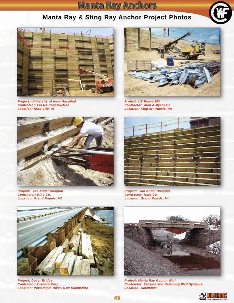
®
FORM ENGINEERING CORP.
Project: University of Iowa HospitialProject: University of Iowa HospitialContractor: Fraser ConstructionContractor: Fraser ConstructionLocation: Iowa CityLocation: Iowa City, IA, IA
Project: VProject: Van an Andel HospitalAndel HospitalContractor: King Co.Contractor: King Co.Location: Grand Rapids, MILocation: Grand Rapids, MI
Project: Dover BridgeProject: Dover BridgeContractor: Cianbro Corp.Contractor: Cianbro Corp.Location: Picsategua RiverLocation: Picsategua River, New Hampshire, New Hampshire
Manta Ray &Manta Ray & Sting Ray Sting Ray Anchor Project PhotosAnchor Project Photos
Project: Manta Ray Gabion WProject: Manta Ray Gabion WallallContractor: Erosion and Retaining WContractor: Erosion and Retaining Wall Systemsall SystemsLocation: OklahomaLocation: Oklahoma
Project: US Route 202Project: US Route 202Contractor: Contractor: Alan Alan AA Myers Co.Myers Co.Location: King of Prussia, PLocation: King of Prussia, PAA
Project: VProject: Van an Andel HospitalAndel HospitalContractor: King Co.Contractor: King Co.Location: Grand Rapids, MILocation: Grand Rapids, MI
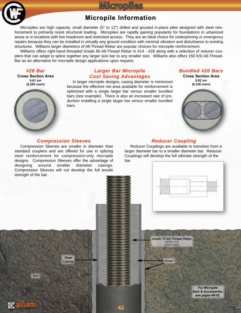
®
FORM ENGINEERING CORP.
#28 Bar#28 BarCross Section Area
9.61 in≈(6,200 mm≈)
Micropile InformationMicropile Information
Micropiles are high capacity, small diameter (5" to 12") drilled and grouted in-place piles designed with steel rein-forcement to primarily resist structural loading. Micropiles are rapidly gaining popularity for foundations in urbanizedareas or in locations with low headroom and restricted access. They are an ideal choice for underpinning or emergencyrepairs because they can be installed in virtually any ground condition with minimal vibration and disturbance to existingstructures. Williams larger diameters of All-Thread Rebar are popular choices for micropile reinforcement.
Williams offers right-hand threaded Grade 80 All-Thread Rebar in #14 - #28 along with a selection of reducer cou-plers that can adapt to splice together any larger size bar to any smaller size. Williams also offers 150 KSI All-Thread-Bar as an alternative for micropile design applications upon request.
Larger Bar MicropileLarger Bar MicropileCost Saving Cost Saving AdvantagesAdvantages
In larger micropile designs, casing diameter is minimizedbecause the effective net area available for reinforcement isoptimized with a single larger bar versus smaller bundledbars (see example). There is also an increased rate of pro-duction installing a single larger bar versus smaller bundledbars.
Bundled #20 BarsBundled #20 BarsCross Section Area
9.82 in≈(6,336 mm≈)
Compression SleevesCompression SleevesCompression Sleeves are smaller in diameter than
standard couplers and are offered for use in splicingsteel reinforcement for compression-only micropiledesigns. Compression Sleeves offer the advantage ofdesigning around smaller diameter casings.Compression Sleeves will not develop the full tensilestrength of the bar.
Reducer CouplingReducer CouplingReducer Couplings are available to transition from a
larger diameter bar to a smaller diameter bar. ReducerCouplings will develop the full ultimate strength of thebar.
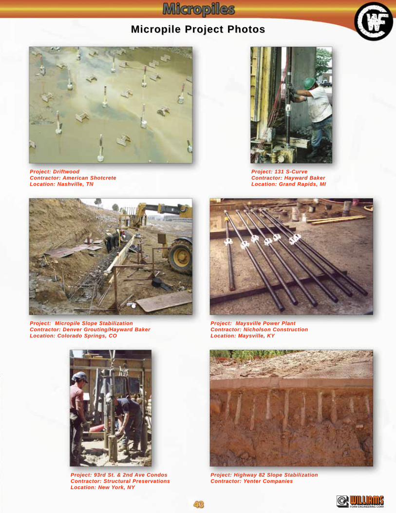
®
FORM ENGINEERING CORP.
Project: DriftwoodProject: DriftwoodContractor: Contractor: American ShotcreteAmerican ShotcreteLocation: Nashville, TNLocation: Nashville, TN
Project: Micropile Slope StabilizationProject: Micropile Slope StabilizationContractor: Denver Grouting/Hayward BakerContractor: Denver Grouting/Hayward BakerLocation: Colorado Springs, COLocation: Colorado Springs, CO
Project: 93rd St. & 2nd Project: 93rd St. & 2nd Ave CondosAve CondosContractor: Structural PreservationsContractor: Structural PreservationsLocation: New Location: New YYork, NYork, NY
Micropile Project PhotosMicropile Project Photos
Project: Highway 82 Slope StabilizationProject: Highway 82 Slope StabilizationContractor: Contractor: YYenter Companiesenter Companies
Project: 131 S-CurveProject: 131 S-CurveContractor: Hayward BakerContractor: Hayward BakerLocation: Grand Rapids, MILocation: Grand Rapids, MI
Project: Maysville Power PlantProject: Maysville Power PlantContractor: Nicholson ConstructionContractor: Nicholson ConstructionLocation: Maysville, KYLocation: Maysville, KY
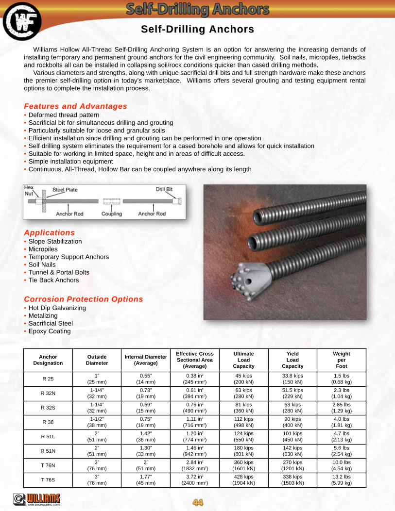
®
FORM ENGINEERING CORP.
Self-Drilling Self-Drilling AnchorsAnchors
Williams Hollow All-Thread Self-Drilling Anchoring System is an option for answering the increasing demands ofinstalling temporary and permanent ground anchors for the civil engineering community. Soil nails, micropiles, tiebacksand rockbolts all can be installed in collapsing soil/rock conditions quicker than cased drilling methods.
Various diameters and strengths, along with unique sacrificial drill bits and full strength hardware make these anchorsthe premier self-drilling option in today's marketplace. Williams offers several grouting and testing equipment rentaloptions to complete the installation process.
Features and Features and AdvantagesAdvantages• Deformed thread pattern• Sacrificial bit for simultaneous drilling and grouting• Particularly suitable for loose and granular soils• Efficient installation since drilling and grouting can be performed in one operation• Self drilling system eliminates the requirement for a cased borehole and allows for quick installation• Suitable for working in limited space, height and in areas of difficult access.• Simple installation equipment• Continuous, All-Thread, Hollow Bar can be coupled anywhere along its length
ApplicationsApplications• Slope Stabilization• Micropiles• Temporary Support Anchors• Soil Nails• Tunnel & Portal Bolts• Tie Back Anchors
Corrosion Protection OptionsCorrosion Protection Options• Hot Dip Galvanizing• Metalizing• Sacrificial Steel• Epoxy Coating
AnchorDesignation
OutsideDiameter
Internal Diameter(Average)
Effective CrossSectional Area
(Average)
UltimateLoad
Capacity
YieldLoad
Capacity
Weightper
Foot
R 251”
(25 mm)0.55”
(14 mm)0.38 in2
(245 mm2)45 kips
(200 kN)33.8 kips(150 kN)
1.5 lbs(0.68 kg)
R 32N1-1/4”
(32 mm)0.73”
(19 mm)0.61 in2
(394 mm2)63 kips
(280 kN)51.5 kips(229 kN)
2.3 lbs(1.04 kg)
R 32S1-1/4”
(32 mm)0.59”
(15 mm)0.76 in2
(490 mm2)81 kips
(360 kN)63 kips
(280 kN)2.85 lbs(1.29 kg)
R 381-1/2”
(38 mm)0.75”
(19 mm)1.11 in2
(716 mm2)112 kips(498 kN)
90 kips(400 kN)
4.0 lbs(1.81 kg)
R 51L2”
(51 mm)1.42”
(36 mm)1.20 in2
(774 mm2)124 kips(550 kN)
101 kips(450 kN)
4.7 lbs(2.13 kg)
R 51N2”
(51 mm)1.30”
(33 mm)1.46 in2
(942 mm2)180 kips(801 kN)
142 kips(630 kN)
5.6 lbs(2.54 kg)
T 76N3”
(76 mm)2”
(51 mm)2.84 in2
(1832 mm2)360 kips
(1601 kN)270 kips
(1201 kN)10.0 lbs(4.54 kg)
T 76S3”
(76 mm)1.77”
(45 mm)3.72 in2
(2400 mm2)428 kips
(1904 kN)338 kips
(1503 kN)13.2 lbs(5.99 kg)

®
FORM ENGINEERING CORP.
Soil NailsSoil NailsThe Williams Self-Drilling Anchor System offers an excellent choice for soil nails when problem soils are encountered.
High rates of production and excellent grout to soil bond strengths are achieved.
MicropilesMicropilesWilliams Self-Drilling Anchors have a natural advantage as a micropile in loose or collapsible soil conditions. A one-
step installation process allows for faster production. The continuous drilling and pressure grouting allow for excellentpenetration of the grout into the surrounding soil allowing for much higher skin friction between the cured grout and thesoil. The bond values obtained are similar to those of post grouting.
Ground Ground AnchorsAnchorsWilliams Self-Drilling Anchors can be used as pre-stressed ground anchors in loose or collapsible conditions. This sys-
tem offers quick installation and eliminates the need for a cased hole. A bond breaker sleeve can be placed on theanchor in the active zone (unbonded length), enabling the anchor to be pre-stressed from the passive zone (bond length).
Self-Drilling Self-Drilling AnchorsAnchors
InstallationInstallationWhen installing in loose or collapsible soil conditions, continuous drilling and grouting is recommended. Feed pressure
on the drill rod should be closely regulated to ensure a continuous, true bore hole that contains full grout coverage.Rotation through the drill hole, as opposed to displacement, must always be achieved. Grout pressure in loose soilsshould progressively increase with depth. Bits are available for all types of ground conditions.
Project: Shattuck RemediationProject: Shattuck RemediationContractor: H&M Consulting & DrillingContractor: H&M Consulting & DrillingLocation: DenverLocation: Denver, CO, CO
Project: TProject: Taos Ski aos Ski AreaAreaContractor: TContractor: Taos Ski aos Ski AreaAreaLocation: TLocation: Taos, NMaos, NM
AnchorDesignation
CouplingDiameter
CouplingLength
NutThickness
NutAcross the Flats
R 251.34”
(34 mm)5.9”
(150 mm)1.38”
(35 mm)
R 32N1.65”
(42 mm)5.9”
(145 mm)1.77”
(45 mm)
R 32S1.65”
(42 mm)7.75”
(190 mm)1.77”
(45 mm)
R 382”
(51 mm)8.7”
(221 mm)1.97”
(50 mm)
R 51L2.48”
(63 mm)5.51”
(140 mm)2.76”
(70 mm)
R 51N2.48”
(63 mm)7.9”
(201 mm)2.76”
(70 mm)
T 76N3.74”
(95 mm)7.9”
(201 mm)3.15”
(80 mm)
T 76S3.74”
(95 mm)7.9”
(201 mm)3.15”
(80 mm)

150 KSI 150 KSI All-Thread-BarAll-Thread-Bar
R71 150 KSI R71 150 KSI All-Thread-BarAll-Thread-Bar - ASTM A722
• Effective cross sectional areas shown are as required byASTM A722-98. Actual areas may exceed these values.
• ACI 355.1R section 3.2.5.1 indicates an ultimate strengthin shear has a range of .6 to .7 of the ultimate tensilestrength. Designers should provide adequate safety factorsfor safe shear strengths based on the condition of use.
• Per PTI recommendations for anchoring, anchors shouldbe designed so that:
• The design load is not more than 60% of the specifiedminimum tensile strength of the prestressing steel.
• The lock-off load should not exceed 70% of the speci-fied minimum tensile strength of the prestressing steel.
• The maximum test load should not exceed 80% of the specified minimum tensile strength of the prestressingsteel.
BarDiameter
MinimumNet Area
Thru Threads
MinimumUltimateStrength
MinimumYield
Strength
NominalWeight
Approx.Thread
Major Dia.
PartNumber
1"(26 mm)
0.85 in2
(549 mm2)127.5 kips(567.1 kN)
102 kips(453.6 kN)
3.09 lbs./ft.(4.6 Kg/M)
1-1/8"(28.6 mm)
R71-08
1-1/4"(32 mm)
1.25 in2
(807 mm2)187.5 kips(834 kN)
150 kips(667.2 kN)
4.51 lbs./ft.(6.71 Kg/M)
1-7/16"(36.5 mm)
R71-10
1-3/8"(36 mm)
1.58 in2
(1019 mm2)237 kips
(1054.2 kN)189.6 kips(843.4 kN)
5.71 lbs./ft.(8.50 Kg/M)
1-9/16"(39.7 mm)
R71-11
1-3/4"(45 mm)
2.60 in2
(1664 mm2)400 kips
(1779.2 kN)320 kips
(1423.4 kN)9.06 lbs./ft.
(13.48 Kg/M)2"
(50.8 mm)R71-14
2-1/2"(65 mm)
5.19 in2
(3350 mm2)778 kips
(3457.0 kN)622.4 kips
(2765.8 kN)18.20 lbs./ft.(27.1 Kg/M)
2-3/4"(69.9 mm)
R71-20
®
FORM ENGINEERING CORP.
Cutting (No WCutting (No Welding)elding)Williams 150 KSI All-Thread-Bar should not be sub-
jected to the heat of a torch, welding or used as aground. Field cutting should be done with an abrasivewheel or band saw.
SizesSizesWilliams 150 KSI bars are manufactured in 5 diameters
from 1” (26 mm) through 2-1/2” (65 mm). Most diametersare available in continuous lengths up to 50’ (15.2 m).
Steel QualitySteel QualityWilliams 1”, 1-1/4”, & 1-3/8” 150 KSI bars are smooth,
hot rolled, high strength prestressing steel. The bars arecold-stressed and stress relieved to produce the aboveproperties. The 1-3/4” & 2-1/2” 150 KSI bars are coldrolled and stressed relieved. All bars are produced toASTM A722-98 physical standards.
Thorough inspection and traceability are carried outduring all phases of manufacturing to assure the higheststandards of quality. Mill certifications and certificates ofconformance can be provided with each shipment as anassurance that the mechanical properties of Williams All-Thread-Bar are as shown.
TTensile Strength &ensile Strength & WWorking Loadsorking LoadsWilliams 150 KSI bars are available with ultimate ten-
sile strengths and working loads as displayed above.Safety factors and functional working loads are at thediscretion of the project design engineer, however testloads should never exceed 80% of the published ultimatebar strength.
PropertiesPropertiesWilliams 150 KSI bars are manufactured in strict com-
pliance with ASTM A722-98 and AASHTO M275Highway Specifications. The prestressing steel is high instrength yet ductile enough to exceed the specified elon-gation and reduction of area requirement. Selectedheats can also pass the 135° supplemental bend testwhen required. Testing has shown Williams 150 KSI All-Thread-Bars to meet or exceed post tensioning bar androck anchoring criteria as set by the Post TensioningInstitute including dynamic test requirements beyond500,000 cycles of loading.
Williams 360° continuous thread deformation patternhas the ideal relative rib area configuration to provideexcellent bond strength capability to grout or concrete,far better than traditional reinforcing deformation pat-terns.
ThreadsThreadsAll-Thread-Bars are cold threaded to close tolerances
under continuous monitoring procedures for quality con-trol. Threads for Williams 150 KSI bar are speciallydesigned with a rugged thread pitch wide enough to befast under job site conditions and easy to assemble.They also have a smooth, wide, concentric, surface suit-able for torque tensioning. This combination offerstremendous installation savings over inefficient, hotrolled, non-concentric thread forms.
Williams All-Thread-Bars are threaded around the fullcircumference enabling the load transfer from the bar tothe fasteners to occur efficiently without eccentric pointloading. Williams fasteners easily meet the allowableload transfer limitations set forth by the Post TensioningInstitute (of the United States). Williams 150 KSI All-Thread-Bars and fasteners are machined to tight toler-ances for superior performance and mechanical lock.Precision machining greatly reduces concern of fastenerloosening or detensioning. 150 KSI bars meet orexceed the deformation requirements under ASTM A615for concrete reinforcing bars. Williams special threaddeformation pattern projects ultra high relative rib area,much greater than conventional rebar. This provides forsuperior bond performance in concrete.

150 KSI 150 KSI All-Thread-Bar All-Thread-Bar AccessoriesAccessories
R73 Hex NutsR73 Hex Nuts - ASTM A29 R72 Stop-TR72 Stop-Type Couplingype Coupling - ASTM A29, Grade C1045
R88 Spherical Hex NutsR88 Spherical Hex Nuts - ASTM A29 R9F Hardened WR9F Hardened Washersashers - ASTM F436
R8M Beveled WR8M Beveled Washersashers - ASTM A47 or ASTM A536R73-JN Jam NutsR73-JN Jam Nuts - ASTM A29, C1045
Note: These Jam Nuts can't be substitute for full strength nutsand can't be used on bars other than Williams 150 KSI All-Thread-Bars of the same diameter.
* Additional USS Hardened Washer required
* Requires a standard nut with spherical washer assembly.Provides up to 5˚ angle when used with a dished plate.
NominalDiameter
OutsideDiameter
OverallLength
PartNumber
1"(26 mm)
1-3/4"(45 mm)
4-1/4"(108 mm)
R72-08
1-1/4"(32 mm)
2-1/8"(54 mm)
5-1/4"(133 mm)
R72-10
1-3/8"(36 mm)
2-3/8"(60 mm)
5-3/4"(146 mm)
R72-11
1-3/4"(45 mm)
3"(76 mm)
8-1/2"(216 mm)
R72-14
2-1/2”(65 mm)
4-1/4”(108 mm)
9-3/8”(238 mm)
R72-20
NominalBar Dia.
AcrossFlats
AcrossCorners
ThicknessPart
Number1"
(26 mm)1-3/4"
(45 mm)2.02"
(51.3 mm)2"
(51 mm)R73-08
1-1/4"(32 mm)
2-1/4"(57 mm)
2.60"(66.0 mm)
2-1/2"(64 mm)
R73-10
1-3/8"(36 mm)
2-1/2"(63.5 mm)
2.89"(73.4 mm)
2-3/4"(70 mm)
R73-11
1-3/4"(45 mm)
3"(76 mm)
3.46"(87.9 mm)
3-1/2"(89 mm)
R73-14
2-1/2"(65 mm)
4-1/4"(108 mm)
4.91"(124.7 mm)
4-3/4"(120 mm)
R73-20
NominalBar Dia.
OutsideDiameter
InsideDiameter
ThicknessPart
Number1"
(26 mm)2-1/4"
(57 mm)1-1/4"
(32 mm)5/32"
(4.0 mm)R9F-09-436
1-1/4"(32 mm)
2-3/4”(70 mm)
1-1/2"(38 mm)
5/32"(3.9 mm)
R9F-11-436
1-3/8"(36 mm)
3"(76 mm)
1-5/8"(41 mm)
5/32"(4.0 mm)
R9F-12-436
1-3/4"(45 mm)
3-3/4"(95 mm)
2-1/8"(54 mm)
7/32"(5.6 mm)
R9F-16-436
2-1/2"(65 mm)
5"(127 mm)
2-7/8"(73 mm)
9/32"(7.1 mm)
R9F-22-436
NominalBar Dia.
Degreeof Bevel
OutsideDiameter
InsideDiameter
MaximumThickness
MinimumThickness
PartNumber
1"(26 mm)
10°2-5/8" sq.(66.7 mm)
1-5/16"(33.3 mm)
13/16"(20.6 mm)
3/8"(9.5 mm)
R8M-08-150
1-1/4" *(32 mm)
15°5-1/4" dia.
(133.4 mm)1-21/32"
(41.9 mm)1-41/64"
(41.7 mm)19/64"
(7.5 mm)R8M-10-150
1-3/8" *(36 mm)
15°5-1/4" dia.
(133.4 mm)1-25/32"
(45.2 mm)1-41/64"
(41.7 mm)19/64"
(7.5 mm)R8M-11-150
1-3/4"(45 mm)
10°5-1/2" dia.
(137.7 mm)2-1/2"
(63.5 mm)1-23/32"
(43.6 mm)3/4"
(20 mm)R8M-14-150
2-1/2"(65 mm)
10°7-1/2" dia.
(190.5 mm)3-1/2"
(88.9 mm)2.31"
(58.7 mm)1"
(26 mm)R8M-20-150
NominalBar Dia.
AcrossFlats
ThicknessOutsideDome
PartNumber
1"(26 mm)
1-3/4"(45 mm)
2-1/4"(57 mm)
2-1/2"(63.5 mm)
R88-08
1-1/4"(32 mm)
2-1/4"(57 mm)
2-3/4"(70 mm)
3-1/8"(79.5 mm)
R88-10
1-3/8"(36 mm)
2-1/2"(63.5 mm)
3-1/4"(82.5 mm)
3-5/8"(90.2 mm)
R88-11
1-3/4"(45 mm)
3"(76 mm)
3-1/2"(89 mm)
4"(101.6 mm)
R88-14
2-1/2" *(65 mm)
4-1/4"(108 mm)
4-3/4"(120 mm)
6"(152 mm)
R73-20
NominalBar Dia.
AcrossFlats
ThicknessPart
Number1"
(26 mm)1-3/4"
(45 mm)1/2"
(12.7 mm)R73-08JN
1-1/4"(32 mm)
2-1/4"(57 mm)
5/8"(15.9 mm)
R73-10JN
1-3/8"(36 mm)
2-1/2"(63.5 mm)
11/16"(17.5 mm)
R73-11JN
1-3/4"(45 mm)
3"(76 mm)
7/8"(22.2 mm)
R73-14JN
2-1/2"(65 mm)
4"(102 mm)
1-3/16"(30.2 mm)
R73-20JN
®
FORM ENGINEERING CORP.
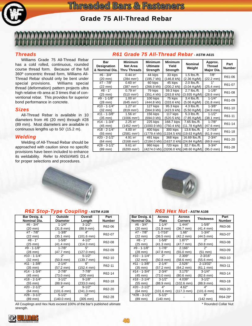
WWeldingeldingWelding of All-Thread Rebar should be
approached with caution since no specificprovisions have been included to enhanceits weldability. Refer to ANSI/AWS D1.4for proper selections and procedures.
SizesSizesAll-Thread Rebar is available in 10
diameters from #6 (20 mm) through #28(89 mm). Most diameters are available incontinuous lengths up to 50’ (15.2 m).
Grade 75 Grade 75 All-Thread RebarAll-Thread Rebar
R62 Stop-TR62 Stop-Type Couplingype Coupling - ASTM A108 R63 Hex NutR63 Hex Nut - ASTM A108
R61 Grade 75 R61 Grade 75 All-Thread RebarAll-Thread Rebar - ASTM A615ThreadsThreadsWilliams Grade 75 All-Thread Rebar
has a cold rolled, continuous, roundedcourse thread form. Because of the full360º concentric thread form, Williams All-Thread Rebar should only be bent underspecial provisions. Williams specialthread (deformation) pattern projects ultrahigh relative rib area at 3 times that of con-ventional rebar. This provides for superiorbond performance in concrete.
* Rounded Collar NutAll Couplings and Hex Nuts exceed 100% of the bar’s published ultimatestrength.
BarDesignation
& Nominal Dia.
MinimumNet Area
Thru Threads
MinimumUltimateStrength
MinimumYield
Strength
NominalWeight
Approx.Thread
Major Dia.
PartNumber
#6 - 3/4"(20 mm)
0.44 in2
(284 mm2)44 kips
(195.7 kN)33 kips
(146.8 kN)1.5 lbs./ft.
(2.36 Kg/M)7/8"
(22.2 mm)R61-06
#7 - 7/8"(22 mm)
0.60 in2
(387 mm2)60 kips
(266.9 kN)45 kips
(200.2 kN)2.0 lbs./ft.
(3.04 Kg/M)1"
(25.4 mm)R61-07
#8 - 1"(25 mm)
0.79 in2
(510 mm2)79 kips
(351.4 kN)59.3 kips
(263.8 kN)2.7 lbs./ft.
(3.935 Kg/M)1-1/8"
(28.6 mm)R61-08
#9 - 1-1/8"(28 mm)
1.00 in2
(645 mm2)100 kips
(444.8 kN)75 kips
(333.6 kN)3.4 lbs./ft.
(5.06 Kg/M)1-1/4"
(31.8 mm)R61-09
#10 - 1-1/4"(32 mm)
1.27 in2
(819 mm2)127 kips
(564.9 kN)95.3 kips
(423.9 kN)4.3 lbs./ft.
(5.50 Kg/M)1-3/8"
(34.9 mm)R61-10
#11 - 1-3/8"(35 mm)
1.56 in2
(1006 mm2)156 kips
(694.0 kN)117 kips
(520.5 kN)5.3 lbs./ft.
(7.85 Kg/M)1-1/2"
(38.1 mm)R61-11
#14 - 1-3/4"(45 mm)
2.25 in2
(1452 mm2)225 kips
(1000.9 kN)168.7 kips(750.4 kN)
7.65 lbs./ft.(11.78 Kg/M)
1-7/8"(47.6 mm)
R61-14
#18 - 2-1/4"(55 mm)
4.00 in2
(2581 mm2)400 kips
(1779.4 kN)300 kips
(1334.5 kN)13.6 lbs./ft.
(19.63 Kg/M)2-7/16"
(61.9 mm)R61-18
#20 - 2-1/2"(64 mm)
4.91 in2
(3168 mm2)491 kips
(2184.0 kN)368 kips
(1637.0 kN)16.69 lbs./ft.(24.84 Kg/M)
2-3/4"(69.9 mm)
R61-20
#28 - 3-1/2"(89 mm)
9.61 in2
(6200 mm2)960 kips
(4274.0 kN)720 kips
(3206.0 kN)32.7 lbs./ft.
(48.60 Kg/M)3-3/4"
(95.0 mm)R61-28
Bar Desig. &Nominal Dia.
OutsideDiameter
OverallLength
PartNumber
#6 - 3/4"(20 mm)
1-1/4"(31.8 mm)
3-1/2"(88.9 mm)
R62-06
#7 - 7/8"(22 mm)
1-3/8"(35.1 mm)
4"(101.6 mm)
R62-07
#8 - 1"(25 mm)
1-5/8"(41.4 mm)
4-1/2"(114.3 mm)
R62-08
#9 - 1-1/8"(28 mm)
1-7/8"(47.7 mm)
5"(127.0 mm)
R62-09
#10 - 1-1/4"(32 mm)
2"(50.8 mm)
5-1/2"(139.7 mm)
R62-10
#11 - 1-3/8"(35 mm)
2-1/4"(57.2 mm)
6"(152.4 mm)
R62-11
#14 - 1-3/4"(45 mm)
2-7/8"(73.0 mm)
7-7/8"(200 mm)
R62-14
#18 - 2-1/4"(55 mm)
3-1/2"(88.9 mm)
9-1/8"(233.0 mm)
R62-18
#20 - 2-1/2"(64 mm)
4"(101.6 mm)
9-1/2"(241.3 mm)
R62-20
#28 - 3-1/2"(89 mm)
5-1/2"(140.0 mm)
12"(305 mm)
R62-28
Bar Desig. &Nominal Dia.
AcrossFlats
AcrossCorners
ThicknessPart
Number#6 - 3/4"(20 mm)
1-1/4"(31.8 mm)
1.444"(36.7 mm)
1-5/8"(41.4 mm)
R63-06
#7 - 7/8"(22 mm)
1-7/16"(36.5 mm)
1.66"(42.2 mm)
1-3/4"(44.5 mm)
R63-07
#8 - 1"(25 mm)
1-5/8"(41.3 mm)
1.877"(47.7 mm)
2"(50.8 mm)
R63-08
#9 - 1-1/8"(28 mm)
1-7/8"(47.8 mm)
2.166"(55.0 mm)
2"(51 mm)
R63-09
#10 - 1-1/4"(32 mm)
2"(50.8 mm)
2.309"(58.6 mm)
2-3/16"(55.6 mm)
R63-10
#11 - 1-3/8"(35 mm)
2-1/4"(57.2 mm)
2.526"(64.2 mm)
2-13/32"(61.1 mm)
R63-11
#14 - 1-3/4"(45 mm)
2-3/4"(73.0 mm)
3.175"(80.6 mm)
3-1/4"(82.6 mm)
R63-14
#18 - 2-1/4"(55 mm)
3-1/2"(88.9 mm)
4.039"(102.6 mm)
3-1/2"(88.9 mm)
R63-18
#20 - 2-1/2"(64 mm)
4"(101.6 mm)
4.62"(117.3 mm)
4"(101.6 mm)
R63-20
*#28 - 3-1/2"(89 mm)
5-1/2"(140 mm)
-6"
(142 mm)R64-28*
®
FORM ENGINEERING CORP.
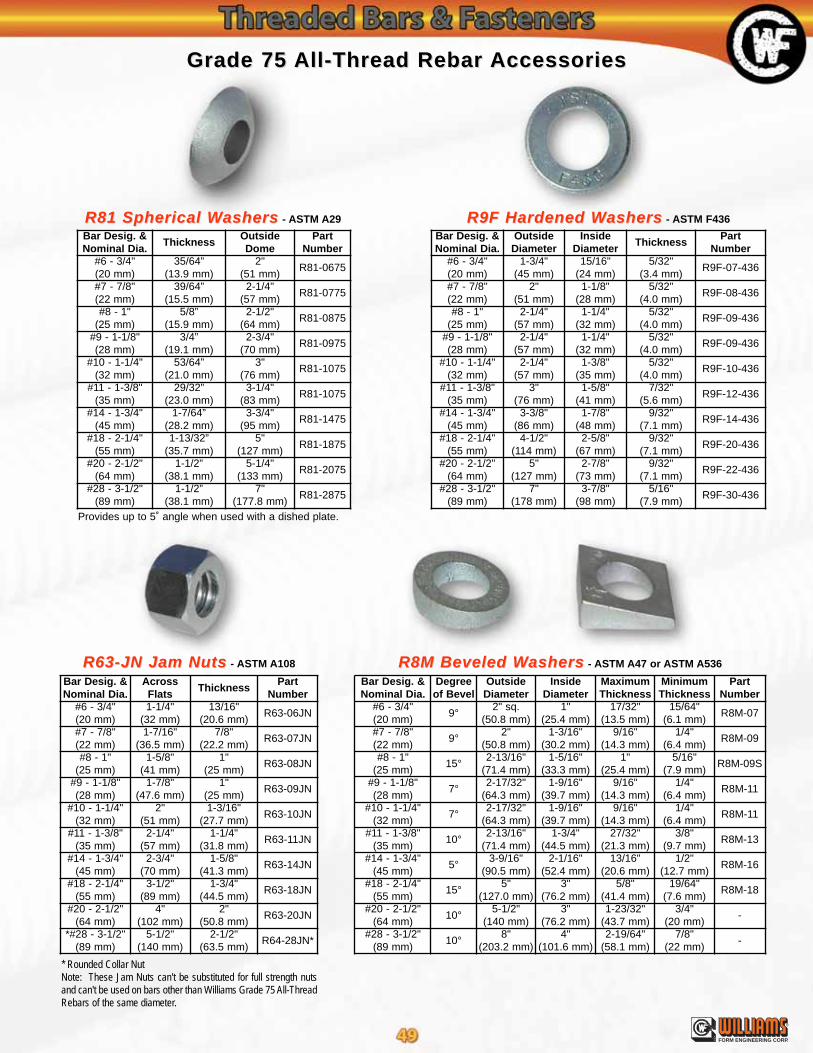
R81 Spherical WR81 Spherical Washersashers - ASTM A29 R9F Hardened WR9F Hardened Washersashers - ASTM F436
R63-JN Jam NutsR63-JN Jam Nuts - ASTM A108 R8M Beveled WR8M Beveled Washersashers - ASTM A47 or ASTM A536
Grade 75 Grade 75 All-Thread Rebar All-Thread Rebar AccessoriesAccessories
* Rounded Collar NutNote: These Jam Nuts can't be substituted for full strength nutsand can't be used on bars other than Williams Grade 75 All-ThreadRebars of the same diameter.
Bar Desig. &Nominal Dia.
OutsideDiameter
InsideDiameter
ThicknessPart
Number#6 - 3/4"(20 mm)
1-3/4"(45 mm)
15/16"(24 mm)
5/32"(3.4 mm)
R9F-07-436
#7 - 7/8"(22 mm)
2"(51 mm)
1-1/8"(28 mm)
5/32"(4.0 mm)
R9F-08-436
#8 - 1"(25 mm)
2-1/4"(57 mm)
1-1/4"(32 mm)
5/32"(4.0 mm)
R9F-09-436
#9 - 1-1/8"(28 mm)
2-1/4"(57 mm)
1-1/4"(32 mm)
5/32"(4.0 mm)
R9F-09-436
#10 - 1-1/4"(32 mm)
2-1/4"(57 mm)
1-3/8"(35 mm)
5/32"(4.0 mm)
R9F-10-436
#11 - 1-3/8"(35 mm)
3"(76 mm)
1-5/8"(41 mm)
7/32"(5.6 mm)
R9F-12-436
#14 - 1-3/4"(45 mm)
3-3/8"(86 mm)
1-7/8"(48 mm)
9/32"(7.1 mm)
R9F-14-436
#18 - 2-1/4"(55 mm)
4-1/2"(114 mm)
2-5/8"(67 mm)
9/32"(7.1 mm)
R9F-20-436
#20 - 2-1/2"(64 mm)
5"(127 mm)
2-7/8"(73 mm)
9/32"(7.1 mm)
R9F-22-436
#28 - 3-1/2"(89 mm)
7"(178 mm)
3-7/8"(98 mm)
5/16"(7.9 mm)
R9F-30-436
Bar Desig. &Nominal Dia.
Degreeof Bevel
OutsideDiameter
InsideDiameter
MaximumThickness
MinimumThickness
PartNumber
#6 - 3/4"(20 mm)
9°2" sq.
(50.8 mm)1"
(25.4 mm)17/32"
(13.5 mm)15/64"
(6.1 mm)R8M-07
#7 - 7/8"(22 mm)
9°2"
(50.8 mm)1-3/16"
(30.2 mm)9/16"
(14.3 mm)1/4"
(6.4 mm)R8M-09
#8 - 1"(25 mm)
15°2-13/16"
(71.4 mm)1-5/16"
(33.3 mm)1"
(25.4 mm)5/16"
(7.9 mm)R8M-09S
#9 - 1-1/8"(28 mm)
7°2-17/32"
(64.3 mm)1-9/16"
(39.7 mm)9/16"
(14.3 mm)1/4"
(6.4 mm)R8M-11
#10 - 1-1/4"(32 mm)
7°2-17/32"
(64.3 mm)1-9/16"
(39.7 mm)9/16"
(14.3 mm)1/4"
(6.4 mm)R8M-11
#11 - 1-3/8"(35 mm)
10°2-13/16"
(71.4 mm)1-3/4"
(44.5 mm)27/32"
(21.3 mm)3/8"
(9.7 mm)R8M-13
#14 - 1-3/4"(45 mm)
5°3-9/16"
(90.5 mm)2-1/16"
(52.4 mm)13/16"
(20.6 mm)1/2"
(12.7 mm)R8M-16
#18 - 2-1/4"(55 mm)
15°5"
(127.0 mm)3"
(76.2 mm)5/8"
(41.4 mm)19/64"
(7.6 mm)R8M-18
#20 - 2-1/2"(64 mm)
10°5-1/2"
(140 mm)3"
(76.2 mm)1-23/32"
(43.7 mm)3/4"
(20 mm)-
#28 - 3-1/2"(89 mm)
10°8"
(203.2 mm)4"
(101.6 mm)2-19/64"
(58.1 mm)7/8"
(22 mm)-
Bar Desig. &Nominal Dia.
ThicknessOutsideDome
PartNumber
#6 - 3/4"(20 mm)
35/64”(13.9 mm)
2"(51 mm)
R81-0675
#7 - 7/8"(22 mm)
39/64”(15.5 mm)
2-1/4"(57 mm)
R81-0775
#8 - 1"(25 mm)
5/8”(15.9 mm)
2-1/2"(64 mm)
R81-0875
#9 - 1-1/8"(28 mm)
3/4”(19.1 mm)
2-3/4"(70 mm)
R81-0975
#10 - 1-1/4"(32 mm)
53/64”(21.0 mm)
3"(76 mm)
R81-1075
#11 - 1-3/8"(35 mm)
29/32”(23.0 mm)
3-1/4"(83 mm)
R81-1075
#14 - 1-3/4"(45 mm)
1-7/64”(28.2 mm)
3-3/4"(95 mm)
R81-1475
#18 - 2-1/4"(55 mm)
1-13/32”(35.7 mm)
5"(127 mm)
R81-1875
#20 - 2-1/2"(64 mm)
1-1/2”(38.1 mm)
5-1/4"(133 mm)
R81-2075
#28 - 3-1/2"(89 mm)
1-1/2”(38.1 mm)
7"(177.8 mm)
R81-2875
Bar Desig. &Nominal Dia.
AcrossFlats
ThicknessPart
Number#6 - 3/4"(20 mm)
1-1/4"(32 mm)
13/16"(20.6 mm)
R63-06JN
#7 - 7/8"(22 mm)
1-7/16"(36.5 mm)
7/8"(22.2 mm)
R63-07JN
#8 - 1"(25 mm)
1-5/8"(41 mm)
1"(25 mm)
R63-08JN
#9 - 1-1/8"(28 mm)
1-7/8"(47.6 mm)
1"(25 mm)
R63-09JN
#10 - 1-1/4"(32 mm)
2"(51 mm)
1-3/16"(27.7 mm)
R63-10JN
#11 - 1-3/8"(35 mm)
2-1/4"(57 mm)
1-1/4"(31.8 mm)
R63-11JN
#14 - 1-3/4"(45 mm)
2-3/4"(70 mm)
1-5/8"(41.3 mm)
R63-14JN
#18 - 2-1/4"(55 mm)
3-1/2"(89 mm)
1-3/4"(44.5 mm)
R63-18JN
#20 - 2-1/2"(64 mm)
4"(102 mm)
2"(50.8 mm)
R63-20JN
*#28 - 3-1/2"(89 mm)
5-1/2"(140 mm)
2-1/2"(63.5 mm)
R64-28JN*
®
FORM ENGINEERING CORP.
Provides up to 5˚ angle when used with a dished plate.
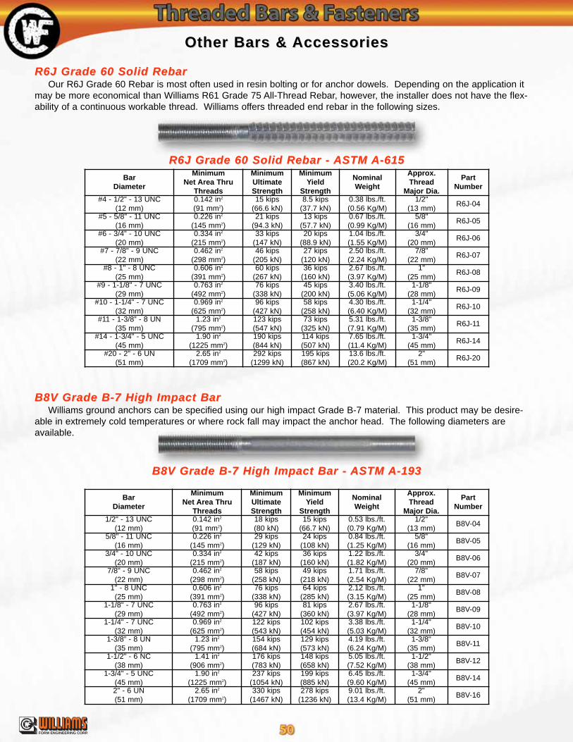
®
FORM ENGINEERING CORP.
Other Bars &Other Bars & AccessoriesAccessories
R6J Grade 60 Solid Rebar - R6J Grade 60 Solid Rebar - ASTM ASTM A-615A-615
B8V Grade B-7 High Impact Bar - B8V Grade B-7 High Impact Bar - ASTM ASTM A-193A-193
R6J Grade 60 Solid RebarR6J Grade 60 Solid RebarOur R6J Grade 60 Rebar is most often used in resin bolting or for anchor dowels. Depending on the application it
may be more economical than Williams R61 Grade 75 All-Thread Rebar, however, the installer does not have the flex-ability of a continuous workable thread. Williams offers threaded end rebar in the following sizes.
B8V Grade B-7 High Impact BarB8V Grade B-7 High Impact BarWilliams ground anchors can be specified using our high impact Grade B-7 material. This product may be desire-
able in extremely cold temperatures or where rock fall may impact the anchor head. The following diameters areavailable.
BarDiameter
MinimumNet Area Thru
Threads
MinimumUltimateStrength
MinimumYield
Strength
NominalWeight
Approx.Thread
Major Dia.
PartNumber
1/2" - 13 UNC(12 mm)
0.142 in2
(91 mm2)18 kips(80 kN)
15 kips(66.7 kN)
0.53 lbs./ft.(0.79 Kg/M)
1/2"(13 mm)
B8V-04
5/8" - 11 UNC(16 mm)
0.226 in2
(145 mm2)29 kips
(129 kN)24 kips
(108 kN)0.84 lbs./ft.(1.25 Kg/M)
5/8"(16 mm)
B8V-05
3/4" - 10 UNC(20 mm)
0.334 in2
(215 mm2)42 kips
(187 kN)36 kips
(160 kN)1.22 lbs./ft.(1.82 Kg/M)
3/4"(20 mm)
B8V-06
7/8" - 9 UNC(22 mm)
0.462 in2
(298 mm2)58 kips
(258 kN)49 kips
(218 kN)1.71 lbs./ft.(2.54 Kg/M)
7/8"(22 mm)
B8V-07
1" - 8 UNC(25 mm)
0.606 in2
(391 mm2)76 kips
(338 kN)64 kips
(285 kN)2.12 lbs./ft.(3.15 Kg/M)
1"(25 mm)
B8V-08
1-1/8" - 7 UNC(29 mm)
0.763 in2
(492 mm2)96 kips
(427 kN)81 kips
(360 kN)2.67 lbs./ft.(3.97 Kg/M)
1-1/8"(28 mm)
B8V-09
1-1/4" - 7 UNC(32 mm)
0.969 in2
(625 mm2)122 kips(543 kN)
102 kips(454 kN)
3.38 lbs./ft.(5.03 Kg/M)
1-1/4"(32 mm)
B8V-10
1-3/8” - 8 UN(35 mm)
1.23 in2
(795 mm2)154 kips(684 kN)
129 kips(573 kN)
4.19 lbs./ft.(6.24 Kg/M)
1-3/8"(35 mm)
B8V-11
1-1/2" - 6 NC(38 mm)
1.41 in2
(906 mm2)176 kips(783 kN)
148 kips(658 kN)
5.05 lbs./ft.(7.52 Kg/M)
1-1/2"(38 mm)
B8V-12
1-3/4" - 5 UNC(45 mm)
1.90 in2
(1225 mm2)237 kips
(1054 kN)199 kips(885 kN)
6.45 lbs./ft.(9.60 Kg/M)
1-3/4"(45 mm)
B8V-14
2" - 6 UN(51 mm)
2.65 in2
(1709 mm2)330 kips
(1467 kN)278 kips
(1236 kN)9.01 lbs./ft.(13.4 Kg/M)
2"(51 mm)
B8V-16
BarDiameter
MinimumNet Area Thru
Threads
MinimumUltimateStrength
MinimumYield
Strength
NominalWeight
Approx.Thread
Major Dia.
PartNumber
#4 - 1/2" - 13 UNC(12 mm)
0.142 in2
(91 mm2)15 kips
(66.6 kN)8.5 kips
(37.7 kN)0.38 lbs./ft.(0.56 Kg/M)
1/2"(13 mm)
R6J-04
#5 - 5/8" - 11 UNC(16 mm)
0.226 in2
(145 mm2)21 kips
(94.3 kN)13 kips
(57.7 kN)0.67 lbs./ft.(0.99 Kg/M)
5/8"(16 mm)
R6J-05
#6 - 3/4" - 10 UNC(20 mm)
0.334 in2
(215 mm2)33 kips
(147 kN)20 kips
(88.9 kN)1.04 lbs./ft.(1.55 Kg/M)
3/4"(20 mm)
R6J-06
#7 - 7/8" - 9 UNC(22 mm)
0.462 in2
(298 mm2)46 kips
(205 kN)27 kips
(120 kN)2.50 lbs./ft.(2.24 Kg/M)
7/8"(22 mm)
R6J-07
#8 - 1" - 8 UNC(25 mm)
0.606 in2
(391 mm2)60 kips
(267 kN)36 kips
(160 kN)2.67 lbs./ft.(3.97 Kg/M)
1"(25 mm)
R6J-08
#9 - 1-1/8" - 7 UNC(29 mm)
0.763 in2
(492 mm2)76 kips
(338 kN)45 kips
(200 kN)3.40 lbs./ft.(5.06 Kg/M)
1-1/8"(28 mm)
R6J-09
#10 - 1-1/4" - 7 UNC(32 mm)
0.969 in2
(625 mm2)96 kips
(427 kN)58 kips
(258 kN)4.30 lbs./ft.(6.40 Kg/M)
1-1/4"(32 mm)
R6J-10
#11 - 1-3/8” - 8 UN(35 mm)
1.23 in2
(795 mm2)123 kips(547 kN)
73 kips(325 kN)
5.31 lbs./ft.(7.91 Kg/M)
1-3/8"(35 mm)
R6J-11
#14 - 1-3/4" - 5 UNC(45 mm)
1.90 in2
(1225 mm2)190 kips(844 kN)
114 kips(507 kN)
7.65 lbs./ft.(11.4 Kg/M)
1-3/4"(45 mm)
R6J-14
#20 - 2" - 6 UN(51 mm)
2.65 in2
(1709 mm2)292 kips
(1299 kN)195 kips(867 kN)
13.6 lbs./ft.(20.2 Kg/M)
2"(51 mm)
R6J-20

®
FORM ENGINEERING CORP.
Other Bars &Other Bars & AccessoriesAccessories
H1F Heavy Duty Hex NutsH1F Heavy Duty Hex Nuts ASTM 194 Grade 2H
R9F Hardened WR9F Hardened Washersashers - ASTM F436 R8M Beveled WR8M Beveled Washersashers - ASTM A47 or ASTM A536
C2TC2T Stop-TStop-Type & C2D Flange Couplingsype & C2D Flange Couplings ASTM A108
R1V Spin-Lock may require a larger coupling diameter.
Bar Diameter
OutsideDiameter
OverallLength
Stop-TypePart Number
Flange CouplingFlange Size Part Number
1/2"(12 mm)
3/4"(19 mm)
1-1/2"(38 mm)
C2T-042” x 2”
(51 x 51 mm)C2D-04
5/8"(16 mm)
1"(25 mm)
1-3/4"(45 mm)
C2T-052” x 2”
(51 x 51 mm)C2D-05
3/4"(19 mm)
1-1/8"(29 mm)
2"(51 mm)
C2T-062” x 2”
(51 x 51 mm)C2D-06
7/8"(22 mm)
1-1/4"(32 mm)
2-1/4"(57 mm)
C2T-073” x 3”
(76 x 76 mm)C2D-07
1"(25 mm)
1-1/2"(38 mm)
3"(76 mm)
C2T-083” x 3”
(76 x 76 mm)C2D-08
1-1/8"(28 mm)
1-5/8"(41 mm)
3-1/2"(89 mm)
C2T-093” x 3”
(76 x 76 mm)C2D-09
1-1/4"(32 mm)
1-7/8"(47 mm)
3-3/4"(95 mm)
C2T-103” x 3”
(76 x 76 mm)C2D-10
1-3/8"(35 mm)
2-1/8"(55 mm)
4"(102 mm)
C2T-113” x 3”
(76 x 76 mm)C2D-11
1-1/2"(38 mm)
2-1/4"(57 mm)
5"(127 mm)
C2T-123” x 3”
(76 x 76 mm)C2D-12
1-3/4"(45 mm)
2-3/4"(70 mm)
5-1/2"(140 mm)
C2T-144” x 4”
(102 x 102 mm)C2D-14
1-7/8"(48 mm)
2-7/8"(73 mm)
6"(152 mm)
C2T-15 - -
2"(51 mm)
3"(76 mm)
6"(152 mm)
C2T-16 - -
Bar Diameter
AcrossFlats
AcrossCorners
ThicknessPart
Number1/2" - 13 UNC
(12 mm)7/8"
(22.2 mm)1.01"
(25.7 mm)31/64"
(12.3 mm)H1F-04
5/8" - 11 UNC(16 mm)
1-1/16"(27.0 mm)
1.227"(31.2 mm)
39/64"(15.5 mm)
H1F-05
3/4" - 10 UNC(19 mm)
1-1/4"(31.8 mm)
1.444"(36.7 mm)
47/64"(18.7 mm)
H1F-06
7/8" - 9 UNC(22 mm)
1-7/16"(36.6 mm)
1.66"(42.2 mm)
55/64"(21.8 mm)
H1F-07
1" - 8 UNC(25 mm)
1-5/8"(41.3 mm)
1.877"(47.7 mm)
63/64"(25.0 mm)
H1F-08
1-1/8" - 9 UNC(28 mm)
1-13/16"(46.0 mm)
2.093"(53.2 mm)
1-7/64"(28.2 mm)
H1F-09
1-1/4" - 6 UNC(32 mm)
2"(50.8 mm)
2.309"(58.6 mm)
1-7/32"(31.0 mm)
H1F-10
1-3/8" - 8 UN(35 mm)
2-3/16"(55.6 mm)
2.526"(64.2 mm)
1-11/32"(34.1 mm)
H1F-11
1-1/2" - 6 NC(38 mm)
2-3/8"(60.3 mm)
2.742"(69.6 mm)
1-15/32"(37.3 mm)
H1F-12
1-3/4" - 5 UNC(45 mm)
2-3/4"(69.9 mm)
3.175"(80.6 mm)
1-23/32"(43.7 mm)
H1F-14
1-7/8" - 8 UN(48 mm)
2-15/16"(74.6 mm)
3.392"(86.2 mm)
1-27/32"(46.8 mm)
H1F-15
2" - 6 UN(51 mm)
3-1/8"(79.4 mm)
3.608"(91.7 mm)
1-31/32"(50.0 mm)
H1F-16
Bar Diameter
OutsideDiameter
InsideDiameter
ThicknessPart
Number1/2" - 13 UNC
(12 mm)1-3/8"
(35 mm)9/16"
(14 mm)9/64"
(3.6 mm)R9F-04-436
5/8" - 11 UNC(16 mm)
1-3/4"(45 mm)
11/16"(17 mm)
9/64"(3.6 mm)
R9F-05-436
3/4" - 10 UNC(19 mm)
1-15/32"(37 mm)
13/16"(21 mm)
9/64"(3.4 mm)
R9F-06-436
7/8" - 9 UNC(22 mm)
1-3/4"(45 mm)
15/16"(24 mm)
5/32"(3.4 mm)
R9F-07-436
1" - 8 UNC(25 mm)
2"(51 mm)
1-1/8"(28 mm)
5/32"(4.0 mm)
R9F-08-436
1-1/8" - 9 UNC(28 mm)
2-1/4"(57 mm)
1-1/4"(32 mm)
5/32"(4.0 mm)
R9F-09-436
1-1/4" - 6 UNC(32 mm)
2-1/4"(57 mm)
1-3/8"(35 mm)
5/32"(4.0 mm)
R9F-10-436
1-3/8" - 8 UN(35 mm)
2-3/4"(70 mm)
1-1/2"(38 mm)
5/32"(4.0 mm)
R9F-11-436
1-1/2" - 6 NC(38 mm)
3"(76 mm)
1-5/8"(41 mm)
5/32"(4.0 mm)
R9F-12-436
1-3/4" - 5 UNC(45 mm)
3-3/8"(86 mm)
1-7/8"(48 mm)
7/32"(5.6 mm)
R9F-14-436
1-7/8" - 8 UN(48 mm)
3-3/4"(95 mm)
2-1/8"(54 mm)
7/32"(5.6 mm)
R9F-16-436
2" - 6 UN(51 mm)
3-3/4"(95 mm)
2-1/8"(54 mm)
7/32"(5.6 mm)
R9F-16-436
Bar Diameter
Degreeof Bevel
OutsideDiameter
InsideDiameter
MaximumThickness
MinimumThickness
PartNumber
1/2"(12 mm)
14°1-1/4"
(32 mm)9/16"
(14 mm)7/16"
(11 mm)1/8"
(3 mm)R8M-04
5/8"(16 mm)
11°1-9/16"
(39.7 mm)13/16"
(20.6 mm)1/2"
(12.7 mm)3/16"
(4.8 mm)R8M-06
3/4"(19 mm)
11°1-9/16"
(39.7 mm)13/16"
(20.6 mm)1/2"
(12.7 mm)3/16”
(4.8 mm)R8M-06
7/8"(22 mm)
9°2"
(50.8 mm)1-3/16"
(30.2 mm)9/16"
(14.3 mm)1/4"
(6.4 mm)R8M-09
1"(25 mm)
9°2"
(50.8 mm)1-3/16"
(30.2 mm)9/16"
(14.3 mm)1/4"
(6.4 mm)R8M-09
1-1/8"(28 mm)
15°2-13/16"
(71.4 mm)1-5/16"
(33.3 mm)1"
(25 mm)5/16"
(7.9 mm)R8M-09S
1-1/4"(32 mm)
7°2-17/32"
(64.3 mm)1-9/16"
(39.7 mm)9/16"
(14.3 mm)1/4"
(6.4 mm)R8M-11
1-3/8"(35 mm)
7°2-17/32"
(64.3 mm)1-9/16"
(39.7 mm)9/16"
(14.3 mm)1/4"
(6.4 mm)R8M-11
1-1/2"(38 mm)
5°3-9/16"
(90.5 mm)2-1/16"
(52.4 mm)13/16"
(20.6 mm)1/2"
(12.7 mm)R8M-16
1-3/4"(45 mm)
5°3-9/16"
(90.5 mm)2-1/16"
(52.4 mm)13/16"
(20.6 mm)1/2"
(12.7 mm)R8M-16
1-7/8"(48 mm)
5°3-9/16"
(90.5 mm)2-1/16"
(52.4 mm)13/16"
(20.6 mm)1/2"
(12.7 mm)R8M-16
2"(51 mm)
5°3-9/16"
(90.5 mm)2-1/16"
(52.4 mm)13/16"
(20.6 mm)1/2"
(12.7 mm)R8M-16

®
FORM ENGINEERING CORP.
End CapsEnd Caps - Williams offers several different types of PVC and metal end caps to provide corrosion protection at oth-erwise exposed anchor ends. Most often the caps are packed with corrosion inhibiting grease. Caps made from steelare used in exposed impact areas.
S1K - Round R80 - Dished S1K - Keyhole S1K - DomedS1K - Studded
NEB 200
CCF1 thru 4E1N
NEB 75R NEB 100
NEB 50NEB 1
CEN PVCCEN PVC CentralizerCentralizerThe Williams PVC Centralizer is used to center the anchor assembly in the
drill hole. They are usually spaced 8 to 10 foot along the bar. To order, specifydrill hole diameter, bar size or the outer diameter of sleeve when used over bar.
Other Other Anchor Anchor AccessoriesAccessories
Bearing PlatesBearing Plates - Williams steel bearing plates are standard with a round hole for non-grouted ground anchors. Alsoavailable are dished plates for use with spherical hex nuts and keyhole plates which provide free access for grout tubeentry. Bearing plates are customized for each application. Plate dimensions should be specified around the parametersof the project. In addition, corrosion protection should be considered along with specifying hole diameter and bar angle.
Eye NutsEye NutsWilliams Eye Nuts may
be used as lifting eyes forforms, concrete blocks, con-crete cylinders, machineryor equipment. The largebase on three of the modelsmakes them excellent foranchoring guy wires. Safetyfactors and working loadsbased on the ultimatestrength of the Eye Nutsshould be determined forthe specific application bythe project design engineer.
Eye NutDesignation
InsideWidth
InsideHeight
RingDiameter
OverallHeight
TapsAvailable
Straight TensionUltimate Strength
Blank PartNumber
NEB 1Malleable
2"(51 mm)
2"(51 mm)
1-1/8"(29 mm)
5-1/8"(130 mm)
3/4"; 7/8"; 1"*(20; 22; 25 mm)
35 kips(156 kN)
E1M-00-001
NEB 50Malleable
3"(76 mm)
3'(76 mm)
1"(25 mm)
5-3/4"(146 mm)
1/2"; 3/4"(13; 20 mm)
26 kips(116 kN)
E1M-00-050
NEB 75RMalleable
4"(102 mm)
5"(127 mm)
1"(25 mm)
7-3/4"(197 mm)
1/2"; 3/4"(13; 20 mm)
23 kips(102 kN)
E1M-00-75R
NEB 100Ductile
4"(102 mm)
4-1/2"(114 mm)
1-1/4”(32 mm)
8"(203 mm)
1"; 1-1/4"; 1-3/8"*(25; 32; 35 mm)
65 kips(289 kN)
E1M-00-100
NEB 200Steel
5"(127 mm)
6"(152 mm)
2"(51 mm)
11"(274 mm)
1-3/8"; 2"(35; 51 mm)
150 kips(667 kN)
E1M-00-200
E1NMalleable
2"(51 mm)
2-1/2"(64 mm)
7/8"(22 mm)
5-1/8"(130 mm)
Grade 75#6, #7, #8
35 kips(156 kN)
E1M-00-E1N
CCF 1CCF 2CCF 3CCF 4Steel
up to4"
(102 mm)
up to6-1/4"
(159 mm)
up to1-1/2"
(38 mm)
up to8-1/2"
(216 mm)
Grade 75#6 through
#18
up to260 kips
(1157 kN)
E1M-00-CCF1E1M-00-CCF2E1M-00-CCF3E1M-00-CCF4
Fiber ReinforcedNylon Cap
Steel Tube welded onFlange with ThreadedScrew Connections
Steel Tubewith Jam Nut
Slip-on PVCCap
Screw-on PVCCap w/ Plastic Nut
* 150 KSI All-Thread-Bar may not be used in 1" diameter for the NEB 1 or in 1-3/8" diameter for the NEB 100.

®
FORM ENGINEERING CORP.
Polyester Resin &Polyester Resin & Bail Bail Anchor Anchor AccessoriesAccessories
Spherical WSpherical WashersashersThese adjustable angle washers are self aligning and
provide full hex nut bearing. They can be used withDomed Plates or with thicker standard plates with cham-fered holes. Use a hardened flat washer between the nutand spherical washer.
Domed PlatesDomed PlatesDomed plates allow for the optimum use of Williams
Spherical Washers to provide high angles of variationbetween the bar and the plate. Plate sizes listed beloware standard. Other sizes are available.
Constant TConstant Torque Nutsorque NutsThese hex nuts have a special compressed end to allow a predictable torque resistance
while torquing the nut/bar on the outer end of a threaded anchor bar. This resistance allows thebar to be rotated by the constant torque nut to mix polyester resin or to initially set a mechani-cal bail anchor. After the resin sets or the bail anchor is set, the nut can then be torqued to ahigher torque to tension the anchor to the required load for a one step installation. Some of thetorque resistance will remain on the nut after the initial “break away” torque.
Constant Torque Nuts are available with UNC or All-Thread Rebar type threads. Allow 1/16”to 1/8” increase in the hex size of the drive socket tool for allowance of the compressed end ofthese nuts. Available for bar sizes listed above. See your Williams representative for the sizeand torque requirements for this product.
Spherical Seat Constant TSpherical Seat Constant Torque Combination Square Nut/Worque Combination Square Nut/WasherasherWilliams has combined the spherical seat washer with a square nut to deliver a one piece
fastener that will both spin the bar and then self align as it contacts the bearing plate. This nutfeatures a constant torque compressed ring to allow a predictable torque resistance similar tothe constant torque nuts above. Some of the torque resistance will remain on the nut after theinitial “break away” torque of approximately 70 ft./lbs. The nut is available only with 1-1/8”square drive and for the following bar sizes: #6 Grade 75 All-Thread Rebar, 3/4”-10 and 7/8”-9UNC, and 3/4”-4-1/2 Coil.
Break Break Away Dome Square NutAway Dome Square NutThis square nut has a thick washer bearing surface and a hollow dome that can be com-
pressed to create the constant torque feature. Unlike the other constant torque nuts, there is notorque resistance after the initial “break away” torque. The nut is available only with 1-1/8”square drive and for the following bar sizes: #6 Grade 75 All-Thread Rebar, 3/4”-10 and 7/8”-9UNC, and 3/4”-4-1/2 Coil.
Note: During installation using constant torque nuts of any type, ensure that the drill hammer is off or the steel shankin the drive steel has been shortened to eliminate any hammering in the drive steel.
Range of Bar Dimensions(Dia. x H x I.D.)
Part NumberUNC/ / Coil Grade 755/8” - 7/8”
(16 - 22 mm)#6
(20 mm)2" x 13/16" x 13/16"(51 x 21 x 21 mm)
FSW-4
7/8” - 1”(22 - 25 mm)
#7(22 mm)
2" x 1/2" x 1-1/16"(51 x 13 x 27 mm)
R81-08-SPFSW-1
7/8” - 1-1/8”(22 - 29 mm)
#7 - #8(22 - 25 mm)
2-1/2" x 3/4" x 1-1/8"(64 x 19 x 29 mm)
R81-08-B
7/8” - 1-1/8”(22 - 29 mm)
#7 - #8(22 - 25 mm)
2-3/4" x 1-3/16" x 1-1/8"(70 x 30 x 29 mm)
R81-08-HDB
1-1/4” - 1-1/2”(32 - 38 mm)
#9 - #11(28 - 35 mm)
3" x 1-1/4" x 1-9/16"(76 x 32 x 40 mm)
R81-11-HD
Plate DimensionsCenterHole
Degree ofRotation
MinimumCollapse Load
3/8" x 6" x 6"(10 x 152 x 152 mm)
1-1/2”(38 mm)
0 - 20°50 kips
(222 kN)3/8" x 6" x 6"
(10 x 152 x 152 mm)1-1/2”
(38 mm)0 - 10°
50 kips(222 kN)
3/8" x 6" x 6"(10 x 152 x 152 mm)
2”(51 mm)
0 - 20°50 kips
(222 kN)3/8" x 6" x 6"
(10 x 152 x 152 mm)2”
(51 mm)0 - 35°
50 kips(222 kN)
1/2" x 8" x 8"(13 x 203 x 203 mm)
2”(51 mm)
0 - 20°100 kips(445 kN)

®
FORM ENGINEERING CORP.
T3PT3P Heavy Duty Plastic Grout THeavy Duty Plastic Grout TubeubeFurnished in product lengths for the rockbolts or in
rolls.
S4Z WIL-KWIK-SETS4Z WIL-KWIK-SETA fast setting cement with an initial set time from 3 to 5 min-
utes. Its primary use is to hold the de-air tube in place and sealoff the entrance to the drill hole around the Williams Hollow-CoreRock Bolt. Mix Wil-Kwik-Set with water until a soft paste isobtained which can be formed into a 4” to 6” ball. Place thegrout tube in the drill hole next to the rock and press a ball of Wil-Kwik-Set around the bolt and tube, making sure the entire drill hole is closed off. Place the bear-ing plate over the end of the rock bolt and grout tube and press firmly against the rock and Wil-Kwik-Set until the plate is well seated against rock. The bolt may immediately be tensioned andgrouted with Wil-X-Cement grout. Wil-Kwik-Set is also recommended for patching leaks, cracks,cone and tie holes, or caulking around pipes in masonry or concrete walls or floors.
T4Z Grout TT4Z Grout Tube ube AdapterAdapterFor down pressure grouting only when grout is forced
through normal grout hole in the hollow rebar.
S5Z WIL-X CEMENT GROUTS5Z WIL-X CEMENT GROUTConforms to ASTM C 845-76 T
Wil-X is chemically compensated for shrinkage. It has ahigh bond value and is crack resistant for permanent installa-tions. Because it is a cement-grout, it is non-explosive and hasa long shelf life when kept dry.
Wil-X may be used to build up leveling pads by simply mix-ing with sand or pea gravel. This mixture should not be runthrough the grout pump.
Setting Time: Gilmore Needles (ASTM C 266). Initial set45 minutes; final set 10 hours.
Comparative compressive strength test in PSI (modifiedASTM C 109)* 3 days in moist air / 4 days in water = 2800 PSI.)Actual strengths as mixed according to Williams instructionsrange from 6,000 to 9,000 PSI depending on water content.* Copy of ASTM Modification available upon request.
5 gallon, resealable,moisture proof,
polypropylene pails
Grout SocksGrout SocksWhat was once consid-
ered to be an impossibleanchorage is made easywith a practical solution fromWilliams. We put GroutSocks on our grout bondedanchors for difficult bondingapplications such asanchors in weak coral orsandstone, highly fracturedrock that can't retain grout,underwater holes in a tidalzone, or holes with artesian flowing water that would nor-mally wash the grout away. The grout sock fabric allowsa limited amount of grout through the sock to provide amaximum bond. Also, since the socks are individuallymanufactured to allow twice the amount of grout as yourdrill hole volume, the grout completely fills the hole underpressure while sealing up adjacent cracks and voids inthe rock. This creates a mechanical lock between theanchor grout column and the rough drill hole surface.
Grouting Grouting AccessoriesAccessories
94 lbs. bag
Super PlasticizerSuper PlasticizerPlasticizer is available and is used as a water reduc-
er for ease of pumping grout through tubes at lowerwater to cement ratios.
Compressive Strength(70° F Dry Environment)
0.4 w/c RatioTime PSI MPa1 Day 1,800 12.43 Days 4,000 27.57 Days 6,000 41.4
O.D. I.D.
3/8”(9.5 mm)
1/4”(6.4 mm)
1/2”(12.7 mm)
3/8”(9.5 mm)
3/4”(19.1 mm)
5/8”(15.9 mm)
Compressive Strength(70° F Dry Environment)
Time PSI MPa1 Hour 600 4.11 Day 3,000 20.77 Days 5,000 34.5
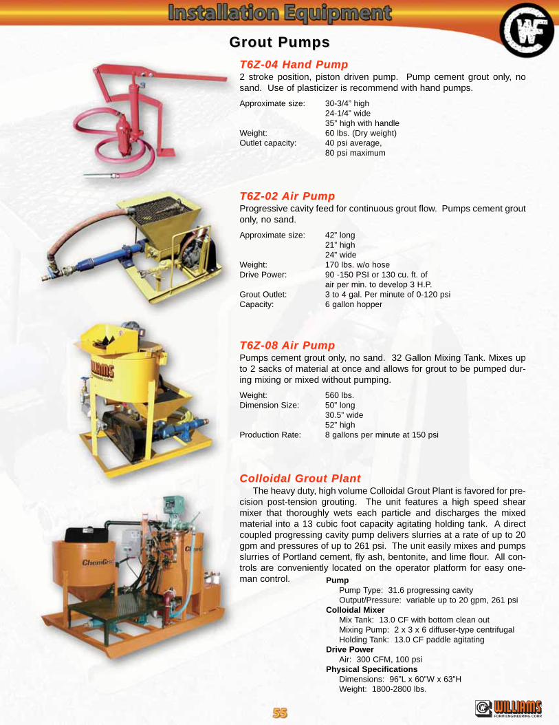
®
FORM ENGINEERING CORP.
Grout PumpsGrout Pumps
T6Z-04 Hand PumpT6Z-04 Hand Pump2 stroke position, piston driven pump. Pump cement grout only, nosand. Use of plasticizer is recommend with hand pumps.
Approximate size: 30-3/4” high24-1/4” wide35” high with handle
Weight: 60 lbs. (Dry weight)Outlet capacity: 40 psi average,
80 psi maximum
T6Z-02 T6Z-02 Air PumpAir PumpProgressive cavity feed for continuous grout flow. Pumps cement groutonly, no sand.
Approximate size: 42” long21” high24” wide
Weight: 170 lbs. w/o hoseDrive Power: 90 -150 PSI or 130 cu. ft. of
air per min. to develop 3 H.P.Grout Outlet: 3 to 4 gal. Per minute of 0-120 psiCapacity: 6 gallon hopper
T6Z-08 T6Z-08 Air PumpAir PumpPumps cement grout only, no sand. 32 Gallon Mixing Tank. Mixes upto 2 sacks of material at once and allows for grout to be pumped dur-ing mixing or mixed without pumping.
Weight: 560 lbs.Dimension Size: 50” long
30.5” wide52” high
Production Rate: 8 gallons per minute at 150 psi
Colloidal Grout PlantColloidal Grout PlantThe heavy duty, high volume Colloidal Grout Plant is favored for pre-
cision post-tension grouting. The unit features a high speed shearmixer that thoroughly wets each particle and discharges the mixedmaterial into a 13 cubic foot capacity agitating holding tank. A directcoupled progressing cavity pump delivers slurries at a rate of up to 20gpm and pressures of up to 261 psi. The unit easily mixes and pumpsslurries of Portland cement, fly ash, bentonite, and lime flour. All con-trols are conveniently located on the operator platform for easy one-man control. Pump
Pump Type: 31.6 progressing cavityOutput/Pressure: variable up to 20 gpm, 261 psi
Colloidal MixerMix Tank: 13.0 CF with bottom clean outMixing Pump: 2 x 3 x 6 diffuser-type centrifugalHolding Tank: 13.0 CF paddle agitating
Drive PowerAir: 300 CFM, 100 psi
Physical SpecificationsDimensions: 96”L x 60”W x 63”HWeight: 1800-2800 lbs.

®
FORM ENGINEERING CORP.
T80 Post-TT80 Post-Tension Hydraulic Jacksension Hydraulic JacksWith the T80 series the enclosed bearing housing contains a geared socket drive to tighten the bolt hex nut during
tensioning. Test jack housing will accommodate up to a 9” deep pocket.
T7Z Open Frame Hydraulic JacksT7Z Open Frame Hydraulic JacksUsed for testing and pre-stressing All-Thread-Bars. Available with up to 5-1/8” center hole. Unit comes with ram,
pump, gauge, hoses, jack stand, high strength coupling, high strength test rod, plate, hex nut and knocker wrench.
RamDirectional
Lever Hose fromBottom Fitting
on Jack to Pump
Nut
HydraulicJack
High StrengthExtension Rod
Base
Hose from Pump toTop Fitting on Jack
JackGauge
Hydraulic Pump(Air or Electric Drive
High StrengthCoupling
Plate
Certification of gauge accuracy available on request prior to shipment only.
Hydraulic JacksHydraulic Jacks
JackCapacity
PumpMethod
RamHeight
BaseSize
RamTravel
MinimumTotal Ram& FrameHeight
MaximumTest RodDiameter
RamArea
Approx.Total Ram& FrameWeight
10 tons(89 kN)
HandSingle Acting
5-5/16”(135 mm)
3” Dia.(76 mm)
2-1/2”(64 mm)
8-3/8”(213 mm)
3/4”(19 mm)
2.12 in2
(1,368 mm2)12 lbs.(5.4 kg)
30 tons(267 kN)
HandSingle Acting
6-1/16”(154 mm)
8” x 8”(203 x 203 mm)
3”(76 mm)
19”(483 mm)
1-1/4”(32 mm)
5.89 in2
(3,800 mm2)80 lbs.(36 kg)
60 tons(534 kN)
Hand, Air, or ElectricDouble Acting
9-1/2"(241 mm)
8" x 8"(203 x 203 mm)
5"(127 mm)
29"(737 mm)
2"(51 mm)
12.31 in2
(7,942 mm2)153 lbs.(69 kg)
60 tons(534 kN)
Hand, Air, or ElectricDouble Acting
12-3/4”(324 mm)
9” x 9”(228 x 228 mm)
6-1/2”(165 mm)
29”(737 mm)
2”(51 mm)
12.73 in2
(8,213 mm2)225 lbs.(102 kg)
100 tons(890 kN)
Air or ElectricDouble Acting
13-1/2”(343 mm)
9” x 9”(228 x 228 mm)
6"(152 mm)
35”(889 mm)
3-1/8”(79 mm)
20.63 in2
(13,310 mm2)270 lbs.(123 kg)
100 tons(890 kN)
Air or ElectricDouble Acting
12-3/8"(314 mm)
9" x 9"(228 x 228 mm)
6"(152 mm)
28"(711 mm)
2"(51 mm)
20.03 in2
(12,923 mm2)192 lbs.(87 kg)
150 tons(1334 kN)
Air or ElectricDouble Acting
12-1/4"(311 mm)
12" x 12"(305 x 305 mm)
5"(127 mm)
32-1/4"(819 mm)
2-1/2"(64 mm)
30.1 in2
(19,419 mm2)350 lbs.(159 kg)
200 tons(1779 kN)
Air or ElectricDouble Acting
16"(406 mm)
12" x 12"(305 x 305 mm)
8"(203 mm)
34"(864 mm)
4"(102 mm)
40.45 in2
(26,097 mm2)518 lbs.(235 kg)
400 tons(3558 kN)
ElectricDouble Acting
18-3/4"(476 mm)
15" Dia.(381 mm)
6"(152 mm)
45-3/4"(1162 mm)
4-1/4"(108 mm)
91.5 in2
(59,032 mm2)1,300 lbs.(590 kg)
400 tons(3558 kN)
ElectricDouble Acting
20-3/8”(518 mm)
17” Dia.(432 mm)
8”(203 mm)
49”(1245 mm)
5”(127 mm)
118.2in2
(76,258 mm2)1,500 lbs.(680 kg)
JackCapacity
PumpMethod
RamHeight
BaseSize
RamTravel
MinimumTotal Ram& FrameHeight
MaximumTest RodDiameter
RamArea
Approx.Total Ram& FrameWeight
60 tons(534 kN)
Hand, Air, or ElectricDouble Acting
9-1/2"(241 mm)
Gear Box: 6.5" x 9.5"(165 x 241 mm)
Cylinder: 3.63" Dia.(92 mm Dia.)
5"(127 mm)
30"(762 mm)
2"(51 mm)
12.31 in2
(7,942 mm2)122 lbs.(55 kg)
60 tons(534 kN)
Hand, Air, or ElectricDouble Acting
12-3/4”(324 mm)
6-1/2”(165 mm)
29”(737 mm)
2”(51 mm)
12.73 in2
(8,213 mm2)225 lbs.(102 kG)
100 tons(890 kN)
Air or ElectricDouble Acting
13-1/2"(343 mm)
Gear Box: 8.5" x 12"(216 x 305 mm)
Cylinder: 4.63" Dia.(118 mm Dia.)
6"(152 mm)
25"(635 mm)
3-1/8"(79 mm)
20.63 in2
(13,310 mm2)270 lbs.(123 kg)
150 tons(1334 kN)
Air or ElectricDouble Acting
12-1/4"(311 mm)
5"(127 mm)
24"(610 mm)
2-1/2"(64 mm)
30.1 in2
(19,419 mm2)243 lbs.(110 kg)
200 tons(1779 kN)
Air or ElectricDouble Acting
16"(406 mm)
Frame: 11" x 11" Nose: 7” Dia.
8"(203 mm)
37"(940 mm)
4"(102 mm)
40.45 in2
(26,097 mm2)455 lbs.(203 kg)
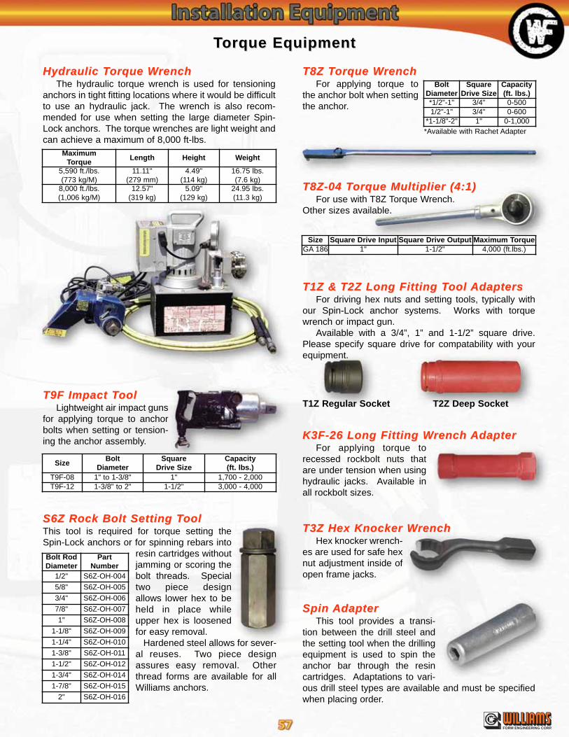
TTorque Equipmentorque Equipment
SizeBolt
DiameterSquare
Drive SizeCapacity(ft. lbs.)
T9F-08 1" to 1-3/8" 1" 1,700 - 2,000T9F-12 1-3/8" to 2" 1-1/2" 3,000 - 4,000
Size Square Drive Input Square Drive Output Maximum TorqueGA 186 1" 1-1/2" 4,000 (ft.lbs.)
MaximumTorque
Length Height Weight
5,590 ft./lbs.(773 kg/M)
11.11"(279 mm)
4.49"(114 kg)
16.75 lbs.(7.6 kg)
8,000 ft./lbs.(1,006 kg/M)
12.57"(319 kg)
5.09"(129 kg)
24.95 lbs.(11.3 kg)
®
FORM ENGINEERING CORP.
S6Z Rock Bolt Setting TS6Z Rock Bolt Setting TooloolThis tool is required for torque setting theSpin-Lock anchors or for spinning rebars into
resin cartridges withoutjamming or scoring thebolt threads. Specialtwo piece designallows lower hex to beheld in place whileupper hex is loosenedfor easy removal.
Hardened steel allows for sever-al reuses. Two piece designassures easy removal. Otherthread forms are available for allWilliams anchors.
T1Z &T1Z & T2Z Long Fitting TT2Z Long Fitting Tool ool AdaptersAdaptersFor driving hex nuts and setting tools, typically with
our Spin-Lock anchor systems. Works with torquewrench or impact gun.
Available with a 3/4”, 1” and 1-1/2” square drive.Please specify square drive for compatability with yourequipment.
K3F-26 Long Fitting WK3F-26 Long Fitting Wrench rench AdapterAdapterFor applying torque to
recessed rockbolt nuts thatare under tension when usinghydraulic jacks. Available inall rockbolt sizes.
T9F Impact TT9F Impact TooloolLightweight air impact guns
for applying torque to anchorbolts when setting or tension-ing the anchor assembly.
T3Z Hex Knocker WT3Z Hex Knocker WrenchrenchHex knocker wrench-
es are used for safe hexnut adjustment inside ofopen frame jacks.
Spin Spin AdapterAdapterThis tool provides a transi-
tion between the drill steel andthe setting tool when the drillingequipment is used to spin theanchor bar through the resincartridges. Adaptations to vari-ous drill steel types are available and must be specifiedwhen placing order.
T8Z TT8Z Torque Worque WrenchrenchFor applying torque to
the anchor bolt when settingthe anchor.
T8Z-04 TT8Z-04 Torque Multiplier (4:1)orque Multiplier (4:1)For use with T8Z Torque Wrench.
Other sizes available.
*Available with Rachet Adapter
Hydraulic THydraulic Torque Worque WrenchrenchThe hydraulic torque wrench is used for tensioning
anchors in tight fitting locations where it would be difficultto use an hydraulic jack. The wrench is also recom-mended for use when setting the large diameter Spin-Lock anchors. The torque wrenches are light weight andcan achieve a maximum of 8,000 ft-lbs.
T1Z Regular Socket T2Z Deep Socket
Bolt RodDiameter
PartNumber
1/2" S6Z-OH-004
5/8" S6Z-OH-005
3/4" S6Z-OH-006
7/8" S6Z-OH-007
1" S6Z-OH-008
1-1/8" S6Z-OH-009
1-1/4" S6Z-OH-010
1-3/8" S6Z-OH-011
1-1/2" S6Z-OH-012
1-3/4" S6Z-OH-014
1-7/8" S6Z-OH-015
2" S6Z-OH-016
BoltDiameter
SquareDrive Size
Capacity(ft. lbs.)
*1/2"-1" 3/4" 0-5001/2"-1" 3/4" 0-600
*1-1/8"-2" 1" 0-1,000
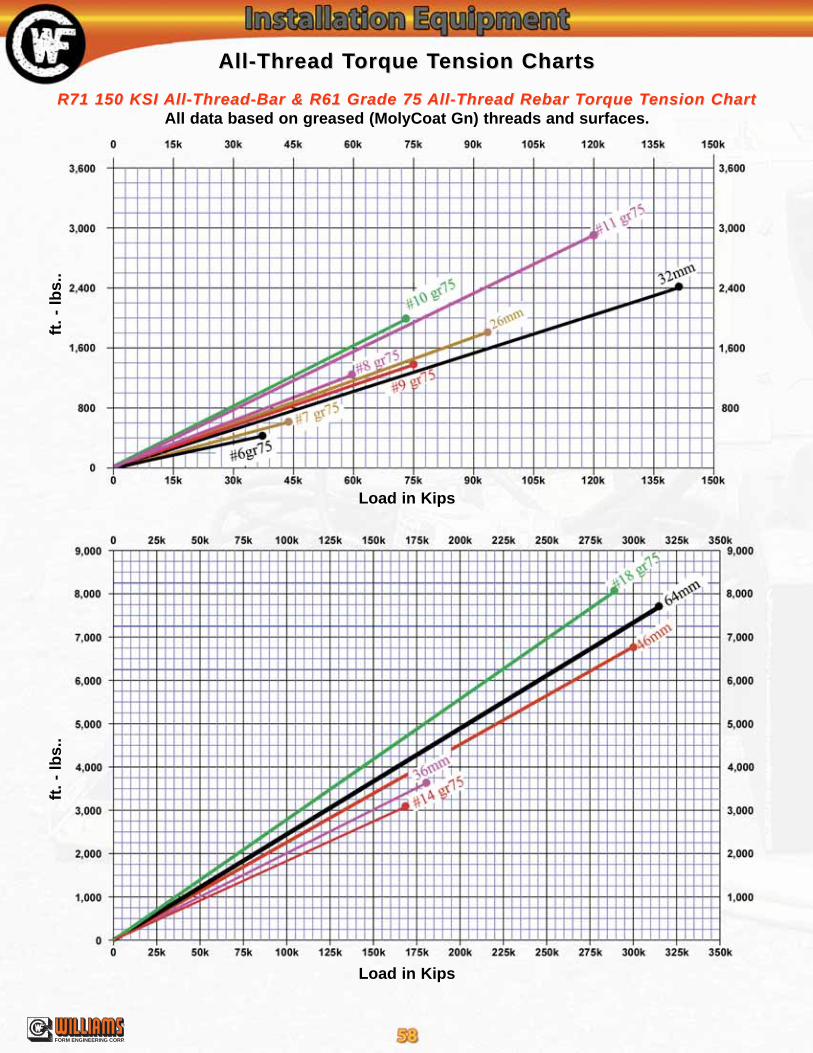
All-Thread TAll-Thread Torque Torque Tension Chartsension Charts
R71 150 KSI R71 150 KSI All-Thread-Bar & R61 Grade 75 All-Thread-Bar & R61 Grade 75 All-Thread Rebar TAll-Thread Rebar Torque Torque Tension Chartension ChartAll data based on greased (MolyCoat Gn) threads and surfaces.
ft.
- lb
s..
ft.
- lb
s..
Load in Kips
Load in Kips
®
FORM ENGINEERING CORP.

Spin-Lock TSpin-Lock Torque Torque Tension Chartsension Chartsft
. -
lbs.
.ft
. -
lbs.
.
Load in Kips
Load in Kips
For R1J bars use R1S values.
For R1J bars use R1S values.
R1H Hollow-Core, R1V High Impact, R1S High TR1H Hollow-Core, R1V High Impact, R1S High Tensile,ensile,R1J Solid Rebar & R7S 150 KSI Spin-Lock TR1J Solid Rebar & R7S 150 KSI Spin-Lock Torque Torque Tension Chartension Chart
®
FORM ENGINEERING CORP.

670 Industrial RoadLondon, Ontario, Canada
Phone: (519) 659-9444Fax: (519) 659-5880
N5V 1V1
Montreal, P.Q.Phone: (514) 696-6233
Fax: (514) 696-9660H8Z 2T1
Please see website for most current informationWeb: http://www.williamsform.comE-mail: [email protected]
Main Office &Main Office & International DivisionInternational Division280 Ann St. N.W.
Grand Rapids, MI 49504Phone: (616) 365-9220
Sales/Engr. Fax (616) 365-2668
FORM HARDWARE & ROCK BOLT (Canada) LTD.
High CapacityConcrete Anchors
Concrete FormingHardware Systems
Post TensioningSystems
Tie Rod & Tie-BackAnchor Systems
Self-DrillingAnchor Systems
Williams offers a full line of Ground Anchors, Concrete Anchors, Post-Tensioning Systems,and Concrete Forming Hardware Systems for whatever your needs may be.
Also available from Williams are Rock & Soil Anchor Sample Specifications,High Capacity Concrete Anchor Sample Specifications, and our Interactive CD Rom
Williams Form Engineering has representation in the following organizations:
7601 North ColumbiaPortland, OR 97203
Phone: (503) 285-4548Fax: (503) 285-6858
251 Rooney RoadGolden, CO 80401
Phone: (303) 216-9300Fax: (303) 216-9400
4170 Vansant RoadDouglasville, GA 30135Phone: (770) 949-8300
Fax: (770) 949-2377
41 - 2nd Ave. S, Bldg. 1Phoenixville, PA 19460Phone: (610) 415-9910
Fax: (610) 415-9920