ground clearance analysis of passenger cars using ... · dr. peter riede introduction aspects of...
TRANSCRIPT
Dr. Peter Riede
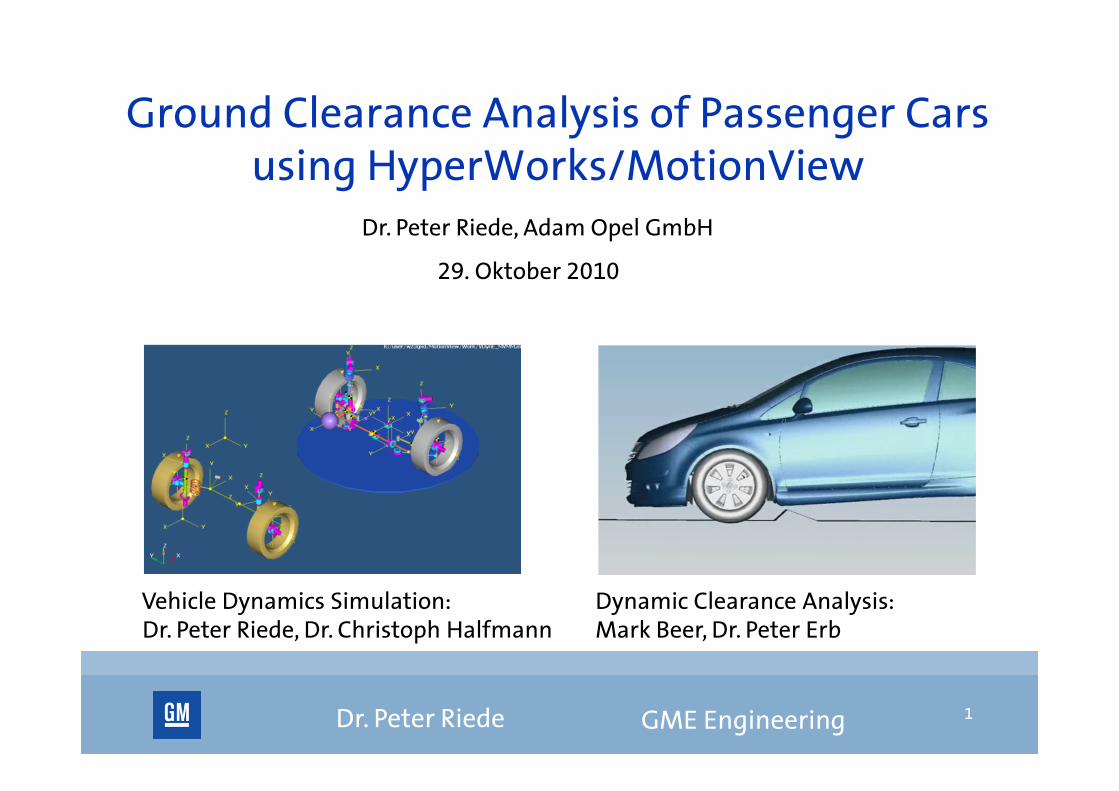
Dr. Peter Riede, Adam Opel GmbH
Vehicle Dynamics Simulation: Dynamic Clearance Analysis:Dr. Peter Riede, Dr. Christoph Halfmann Mark Beer, Dr. Peter Erb
Ground Clearance Analysis of Passenger Cars using HyperWorks/MotionView
29. Oktober 2010
GME Engineering 1
Dr. Peter Riede
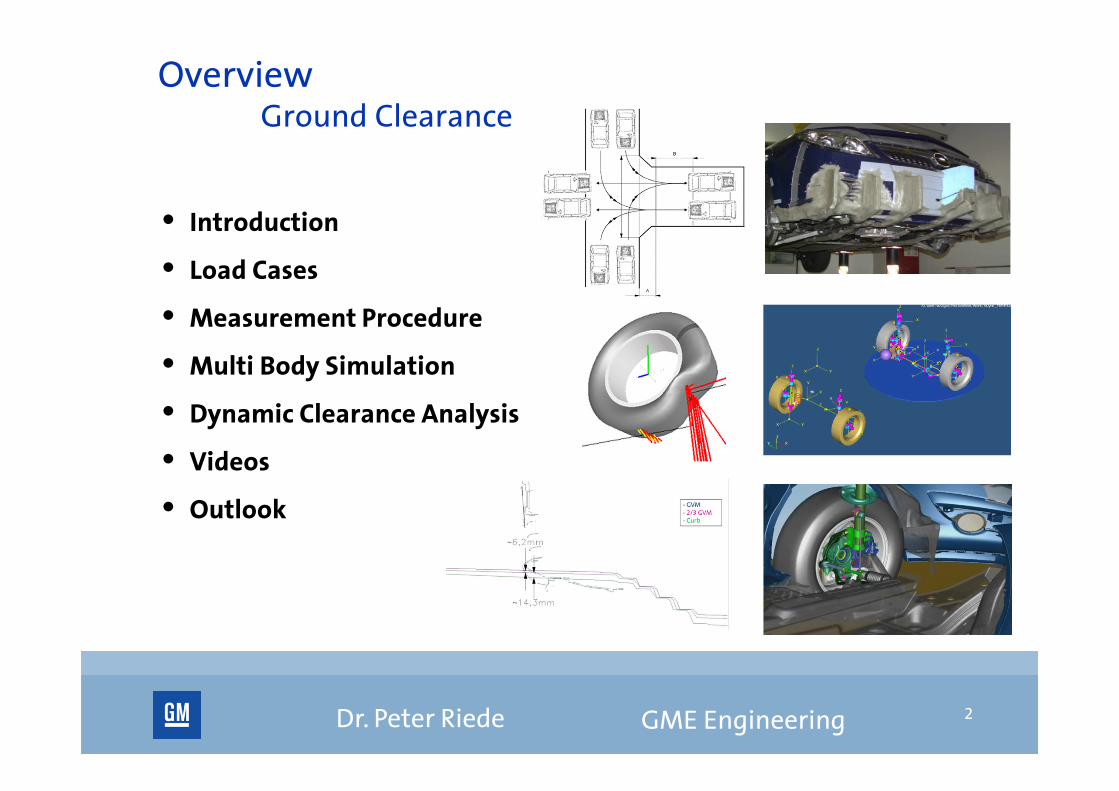
OverviewGround Clearance
• Introduction
• Load Cases
• Measurement Procedure
• Multi Body Simulation
• Dynamic Clearance Analysis
• Videos
• Outlook
GME Engineering 2

Dr. Peter Riede
IntroductionAspects of Ground Clearance
Building Fuel Saving Cars
• Reduction of trim height (distance between wheel center and chassis)
• Packaging: Optimal usage of the space under the car
• Additional underbody panels to improve aerodynamic behaviour
Goal:
Optimize the design of the underbody in a way that ground clearance criteria are still fulfilled!
GME Engineering 3

Dr. Peter Riede
IntroductionGround Clearance Criteria
Regular Maneuvers
• No ground contact shall occur.
Heavier Maneuvers
• Damage of car has to be obviated.
Misuse Maneuvers
• All components must remain attached and functional without permanent deformation
• Especially Brake, fuel and drive shaft components shall not be damaged
GME Engineering 4

Dr. Peter Riede
IntroductionGround Clearance Criteria
GME Engineering 5

Dr. Peter Riede
Load CasesOverview
• Curb test
• Ramp parking garage
• 13° / 16° US ramp
• Speed humps
• US 7’’’’’’’’ curbstone
Several driving maneuvers per obstacle
GME Engineering 6

Dr. Peter Riede
Load CasesCurb Test
• 12 cm height
• Walking speed (4-5 km/h)
GME Engineering 7

Dr. Peter Riede
Load CasesRamp Parking Garage
• Forward and rearward driving
• Parking lot speed (10 km/h)
• Edges rounded
GME Engineering 8

Dr. Peter Riede
Load Cases13°/16° US Ramp
• 13° ramp: Walking speed (4-5 km/h)
• 16° ramp: Creep speed (1-2 km/h, heavy contact & damage to soft components expected)
GME Engineering 9

Dr. Peter Riede
Load CasesSpeed Humps
• Walking speed (4-5 km/h)
GME Engineering 10
Dr. Peter Riede
Load CasesUS 7’’ curbstone
• 18 cm height
• Walking speed (4-5 km/h)
• Forward and rearward driving
• Drive until the tire contacts the curbstone, or the vehicle stops
GME Engineering 11

Dr. Peter Riede
Measurement Procedure
• Seven bars of plasticine on the underbody
• Grinding of “ground lines” in theplasticine by driving over the obstacles
• Heightened trim height
• Digitalization of the ground lines with point taker for further constructional evaluation
GME Engineering 12

Dr. Peter Riede
Multi Body SimulationSimulation vs. Measurement
Disadvantages of measurement procedure
• Laborious to prepare cars
• Usually evaluation of all load cases at once
Advantages of simulation
• Evaluations of ground clearance long before first prototypes
• Saving of real test runs ( saving of time and money)
• Verification of more variants
• Fast parameter studies to analyze influence of speed, steering angle, …
GME Engineering 13

Dr. Peter Riede
Multi Body Simulation Tasks of Simulation
• Calculate the minimal distance of every point of the underbody to the ground to explore maximal construction space
• Detect points of collisions
• Prediction of the dimension of the damage not possible
GME Engineering 14
Dr. Peter Riede
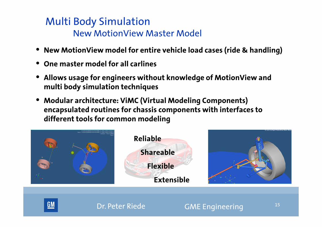
• New MotionView model for entire vehicle load cases (ride & handling)
• One master model for all carlines
• Allows usage for engineers without knowledge of MotionView and multi body simulation techniques
• Modular architecture: ViMC (Virtual Modeling Components) encapsulated routines for chassis components with interfaces to different tools for common modeling
GME Engineering 15
Multi Body Simulation New MotionView Master Model
Reliable
Shareable
Flexible
Extensible

Dr. Peter Riede
• Linkage of FTire to MotionView (complex tiremodel, also regarding deflection)
• Dynamical simulation of entire vehicle
• Velocity controller
• Calculation of the motion of the bodies
• Trajectory of body to determine translational motions
• Tensor of directional cosinuses for rotational motions
GME Engineering 16
Multi Body Simulation Simulation Techniques
Dr. Peter Riede
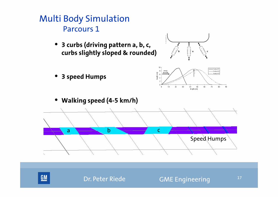
Multi Body Simulation Parcours 1
• 3 curbs (driving pattern a, b, c,curbs slightly sloped & rounded)
• 3 speed Humps
• Walking speed (4-5 km/h)
• Forward and rearward driving
GME Engineering 17
a b c
Speed Humps

Dr. Peter Riede
Multi Body Simulation Parcours 2
13° Ramp
• Walking speed (4-5 km/h)
• 5 different angles (0, +/-30°, +/-60°)
• Forward and rearward driving
GME Engineering 18

Dr. Peter Riede
Multi Body Simulation Parcours 3
16° Ramp
• Creep speed (1-2 km/h)
• 5 different angles (0, +/-30°, +/-60°)
• Forward and rearward driving
GME Engineering 19

Dr. Peter Riede
Multi Body Simulation Parcours 3
Ramp Parking Garage
• Parking lot speed (10 km/h)
• Forwards up and rearwards down
• Velocity Controller
GME Engineering 20

Dr. Peter Riede
• Input: Motions calculated by MBS simulation(Trajectories and rotation tensors)
• Usage of CAD models of chassis & underbody
• Calculation of ground clearance (minimal distances of chassis & underbody to ground)
• Fast and easy identification of critical points and critical maneuvers
• Creation of video sequences for presentation purposes
GME Engineering 21
Dynamic Clearance AnalysisGround Clearance Analysis based on Simulation Results
Dr. Peter Riede GME Engineering 22
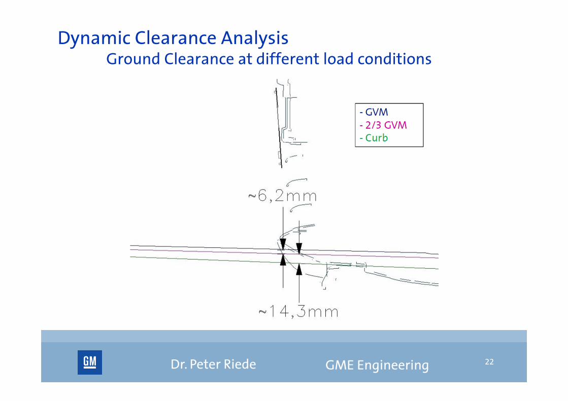
Dynamic Clearance AnalysisGround Clearance at different load conditions
Dr. Peter Riede GME Engineering 23
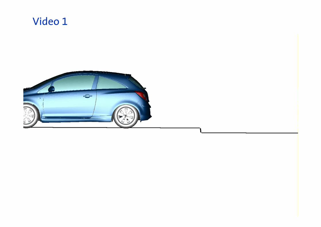
Video 1

Dr. Peter Riede GME Engineering 24
Video 2

Dr. Peter Riede
• Steering controller for steered maneuvers
• Sensitivity studies for the load case parameters like speed and steering angle in order to find out if load cases are redundant. Objective is to have a small set of optimized load cases that cover all customer relevant aspects of ground clearance.
• Create a map of the underbody showing which areas are critical at which of the load cases. If modification of certain parts of the underbody is considered the corresponding relevant load cases are known.
GME Engineering 25
Outlook

Dr. Peter Riede 26