ground movement control - amazon web services · an nzgs 1 day short course ground movement control...
TRANSCRIPT

An NZGS 1 day short course
Ground movement control
Deep excavations
Antonio GensTechnical University of Catalonia, Barcelona, Spain

Outline
Introduction. Generation of ground movements by deep excavations
Empirical methods for estimating ground movements
Methods for calculating ground movements
Procedures for control and reduction of movements
A case history
Excavations with large movements: announcing failure?
Conclusions

The performance of an excavation with retaining walls inevitably causes movements in the wall and surrounding ground
We will mainly focus on “normal” movements (i.e. on those corresponding to an adequate construction not on those arising from accidents)
We will focus on movements associated basically to the excavation process
Tolerance concerning the acceptable deformation level (in urban environment) has reduced significantly in recent years
It means enhanced requirements for estimation and control of movements
Excavation-induced ground movements

Deformation mechanisms
Two basic deformation modes
Cantilever wall Propped wall Total displacements

Surface horizontal displacements often ignored they are more difficult to measure (less experience)
Lion Yard excavation (Ng, 1998)
Deformation mechanisms

Tension horizontal deformation contributes significantly to damage of buildings and structures
Boscardin & Cording (1989) Burland (1998)
Deformation mechanisms

Tension
Deformation mechanisms
Tension horizontal strains contribute significantly to the damage of buildings and structures the majority of horizontal strains associated to deep excavations are tension strains
(more unfavourable than in the tunnelling case)
the response of a building may depend significantly on its horizontal stiffness
Tunnels
CompressionTension
Tension
Tension
Excavations
Hor.
Vert.
Hor.
Vert.

Deformation mechanisms
Factors that influence ground movements caused by excavations stress changes in the ground (due to excavation and construction)
excavation size (depth and width)
ground properties
initial horizontal stresses in the ground
hydraulic conditions and their variation
wall and prop stiffness
preloading of propos and anchors
external loads
construction procedure
construction quality
others...

Esquema de la presentación
Introduction. Generation of ground movements by deep excavations
Empirical methods for estimating ground movements
Methods for calculating ground movements
Procedures for control and reduction of movements
A case history
Excavations with large movements: announcing failure?
Conclusions

Empirical methods for evaluating movements
I: sands and soft clays, standard construction qualityII: soft and very soft claysIII: soft and very soft clays reaching below excavation depth
Curves obtained from excavations with sheet pile walls or soldier piles. Reduced embedment
Settlements
(Peck,1969)
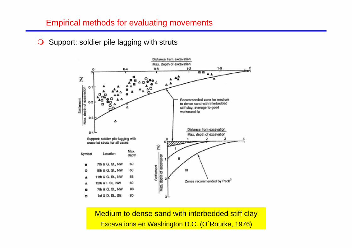
Support: soldier pile lagging with struts
Medium to dense sand with interbedded stiff clayExcavations en Washington D.C. (O´Rourke, 1976)
Empirical methods for evaluating movements

Empirical methods for evaluating movements
Stiff clays, residual soils and sands (Clough & O’ Rourke, 1990)
Maximum lateral movement Maximum settlement
The mean of maximum lateral movements measured around 0.2% The mean of maximum settlements measured around 0.15 % Large scatter, more in horizontal movements No significant differences between different wall types

Empirical methods for evaluating movements
Soft clays (Mana & Clough, 1981)
Movements associated to bottom instability are dominant when the factor of safety is low
Maximum horizontal movement
Bottom instability

Empirical methods for evaluating movements
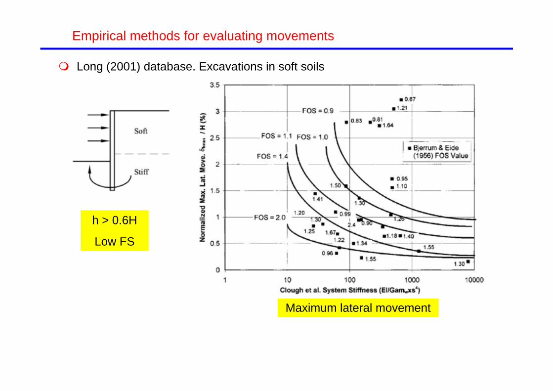
Soft clays (Clough & O’ Rourke, 1990)
System stiffness: (EI)/(wh4) Addenbrooke et al. (2000) defined system stiffness as (EI)/(wh5)
Maximum lateral movements Settlements

Empirical methods for evaluating movements
Other databases
Karlsrud (1986): Oslo soft clay
Ou et al. (1993): Taipei soft clay
Wong et al. (1997): Singapore
Carder (1995): UK
Fernie and Suckling (1996): UK
Long (2001): 296 cases! (COST Action C-7)

Empirical methods for evaluating movements
Long (2001) database. Excavations in medium and stiff soils
Maximum lateral movement Maximum settlement
Large scatter Generally values smaller than those collected by Clough & O’Rourke (1990) Little influence of the type of bracing (props, anchors, top-down)
Empirical methods for evaluating movements
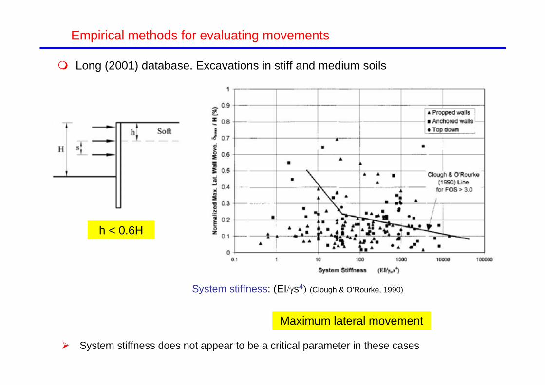
Long (2001) database. Excavations in stiff and medium soils
Maximum lateral movement
h < 0.6H
System stiffness does not appear to be a critical parameter in these cases
System stiffness: (EIs4 (Clough & O’Rourke, 1990)

Empirical methods for evaluating movements
Long (2001) database. Excavations in stiff and medium soils
Maximum lateral movement
h < 0.6H
System flexibility does not appear to be a critical parameter in these cases
Flexibility number: (s5)/(EI) (Addenbrooke et al., 2000)

Empirical methods for evaluating movements
Long (2001) database. Excavations in soft soils
Maximum lateral movement
h > 0.6H
Low FS
Empirical methods for evaluating movements
Long (2001) database. Excavations in soft soils
Maximum lateral movement
h > 0.6H
Low FS

Empirical methods for evaluating movements
Long (2001) database: causes of excessive movements (with respect to the majority of works in similar circumstances). 36 cases examined
Excessive movements in cantilever mode: 12 cases
Wall too flexible: 8 cases
Creep of anchors/props: 3 cases
Structural yielding: 2 cases
Water inflow: 1 case
Pile driving: 1 case
Unknown: 9 cases

Distribution of surface settlements (Clough & O’Rourke, 1990)
Sands
Empirical methods for evaluating movements
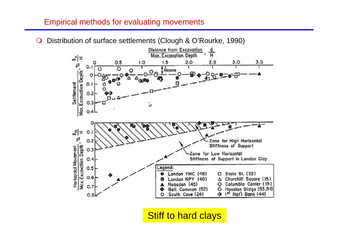
Distribution of surface settlements (Clough & O’Rourke, 1990)
Stiff to hard clays
Empirical methods for evaluating movements

Chicago excavations (O´Rourke, 1976)
Distribution of surface settlements (Clough & O’Rourke, 1990)
Empirical methods for evaluating movements
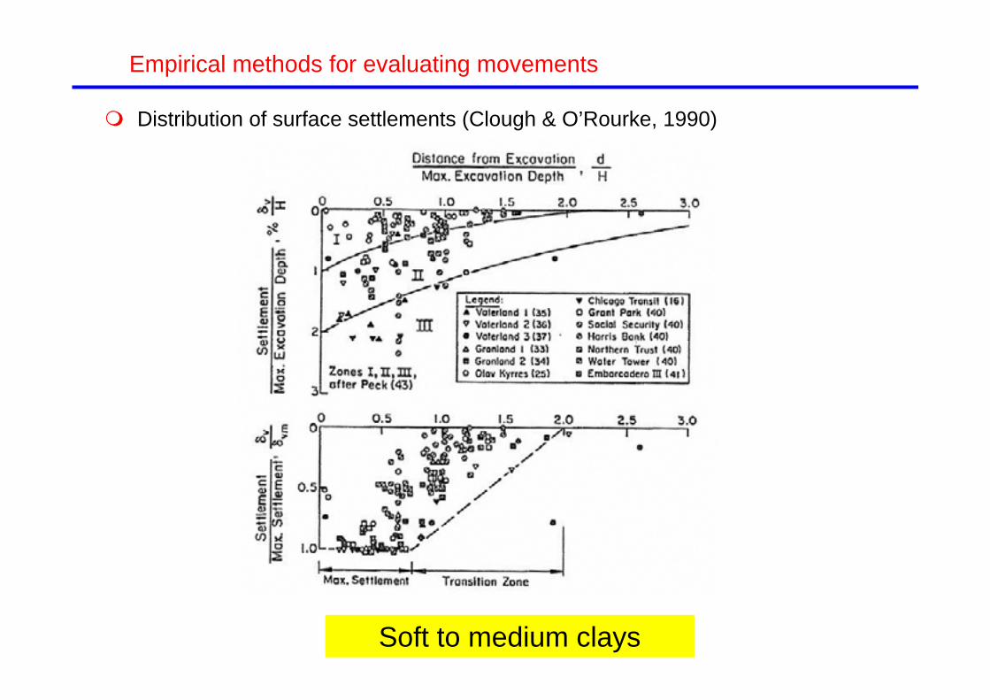
Distribution of surface settlements (Clough & O’Rourke, 1990)
Soft to medium clays
Empirical methods for evaluating movements

Distribution of surface settlements (Clough & O’Rourke, 1990)
Sands Stiff to hard clays
Soft to medium clays
Empirical methods for evaluating movements

Distribution of surface settlements (Hsieh and Ou, 1998) They suggest that the shape of the settlement distribution is related to the type
of wall deformation
Ac
As
Spandrel (cantilever) type
Concave type
Empirical methods for evaluating movements

Distribution of surface settlements (Hsieh and Ou, 1998) Estimation method
Spandrel (cantilever) type Concave type
Empirical methods for evaluating movements

Distribution of surface settlements (Hsieh and Ou, 1998) Excavation in soft silty clay near the centre of the Taipei basin
Concave type
Empirical methods for evaluating movements

Distribution of surface settlements (Hsieh and Ou, 1998) Excavation in silty clay for the Far-East Enterprise Center project in Taipei
Empirical methods for evaluating movements
Spandrel (cantilever) type

Relationship between maximum vertical and lateral movement (Hsieh and Ou, 1998)
Empirical methods for evaluating movements
Independent of settlement distribution type
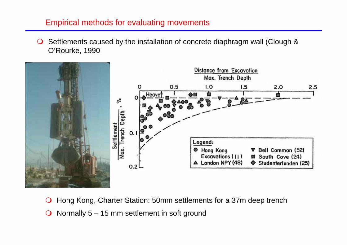
Settlements caused by the installation of concrete diaphragm wall (Clough & O’Rourke, 1990
Empirical methods for evaluating movements
Hong Kong, Charter Station: 50mm settlements for a 37m deep trench
Normally 5 – 15 mm settlement in soft ground

Esquema de la presentación
Introduction. Generation of ground movements by deep excavations
Empirical methods for estimating ground movements
Methods for calculating ground movements
Procedures for control and reduction of movements
A case history
Excavations with large movements: announcing failure?
Conclusions

Calculation methods Limit equilibrium (no information on ground movements) Diaphragm walls considered as elastic beams on springs (Winkler’s
model): RIDO, PARATIE, WALLOP…
Simualtion using finite elements or finite differences: ABAQUS, FLAC, PLAXIS
Methods for calculating ground movements
i

Diaphragm wall considered as beams supported by springs Relatively simple, they require a limited number of hypotheses and data There is a wide experience of their use in practice They allo the introduction of some nonlinearity The subgrade modulus (a key parameter in this type of calculations) is a
parameter with serous limitations The global soil-interaction problem is not considered The horizontal movements of the wall are computed, ground movemnts
must be calculated separately
Methods for calculating ground movements

Finite elements / Finite differences More complex, they require a larger number of hypotheses and decisions
(constitutive model, type of analysis, initial stresses, boundary conditions. domain size…)
There is less experience of use in practice (rapidly changing but… Some models require an information level not always available The allow the consideration of the global problem, they contribute to the
better understanding of deformation and failure mechanisms They provide a quite complete information on stresses, stains,
displacements They are progressively replacing simplified methods Validation/calibration with field measurements are essential
Methods for calculating ground movements

Effect of constitutive model (Schwiger, pers. comm.)Methods for calculating ground movements
23.3m
8.0m
8.0m
19.8m
27°
27°
0.8m
-32.00m = base of diaphragm wall
excavation step 3 = -14.35m
GW = -3.00m below surface
0.00m
excavation step 2 = - 9.30m
excavation step 1 = - 4.80m
30 m
Specification for anchors:prestressed anchor force: 1. row: 768KN 2. row: 945KN 3. row: 980KN
distance of anchors: 1. row: 2.30m 2. row: 1.35m 3. row: 1.35mcross section area: 15 cm2
Young's modulus E = 2.1 e8 kN/m2
top of hydraulic barrier = -30.00m
excavation step 4 = -16.80m-17.90m 23.8m 8.0m
27°
2 - 3 x width of excavation2
- 3 x
wid
th o
f exc
avat
ion
sand
'='sand
x
z
> plane strain> wall "wished-in-place"

Effect of constitutive model Mohr Coulomb vs. Hardening Soil
Methods for calculating ground movements
Mohr-Coulomb Hardening Soil

horizontal displacement [mm]
-60 -55 -50 -45 -40 -35 -30 -25 -20 -15 -10 -5 0
-60 -55 -50 -45 -40 -35 -30 -25 -20 -15 -10 -5 0
dept
h be
low
sur
face
[m]
0
2
4
6
8
10
12
14
16
18
20
22
24
26
28
30
32
MC_1Poisson = 0.2Poisson = 0.4Rinter = 0.5reference solution(Hardening Soil)
Effect of constitutive model Mohr Coulomb vs. Hardening Soil
Methods for calculating ground movements
distance from wall [m]
0 10 20 30 40 50 60 70 80 90 100
verti
cal d
ispl
acem
ents
of s
urfa
ce [m
m]
-30
-25
-20
-15
-10
-5
0
5
10
15
20
25
30
MC_1Poisson = 0.2Poisson = 0.4Rinter = 0.5reference solution(Hardening Soil)
Hard. Soil

Methods for calculating ground movements
Wesminster Palace, London

Clock Tower inclination Prediction: 1:8000 Observation: - 1:8600
Methods for calculating ground movements
Westminster Palce, London

Horizontal and vertical displacements
Methods for calculating ground movements
Mohr-Coulomb model (or any other that incorporates a linear elastic component) Although reasonable wall lateral movements can be obtained,
computed settlements are often in error Excavation bottom heave are considerably overestimated The location of the lower boundary of the calculation domain has an
decisive influence on computed displacements In the case of excavations in soft soils, the effects are less marked
because the soil shear strength plays a dominant role
Methods for calculating ground movements

Effect of the friction between soil and wallMethods for calculating ground movements
horizontal displacement [mm]
-70 -65 -60 -55 -50 -45 -40 -35 -30 -25 -20 -15 -10 -5 0
-70 -65 -60 -55 -50 -45 -40 -35 -30 -25 -20 -15 -10 -5 0
dept
h be
low
sur
face
[m]
0
2
4
6
8
10
12
14
16
18
20
22
24
26
28
30
32
reference solution Rinter = 0.8 (final stage) Rinter = 0.5 (final stage)Rinter = 0.8 t_virt = 0.01 (final stage)reference solution(1. excavation stage)Rinter = 0.5 (1. excavation stage) Rinter = 0.8 t_virt = 0.01(1. excavation stage)
distance from wall [m]
0 10 20 30 40 50 60 70 80 90 100
verti
cal d
ispl
acem
ent o
f sur
face
[mm
]
-40
-35
-30
-25
-20
-15
-10
-5
0
5
10
reference solutionRinter = 0.5
R=0.8
R=0.5
R=0.8
R=0.5

Benchmark (Schwiger, 2006)Methods for calculating ground movements
23.3m
8.0m
8.0m
19.8m
27°
27°
0.8m
-32.00m = base of diaphragm wall
excavation step 3 = -14.35m
GW = -3.00m below surface
0.00m
excavation step 2 = - 9.30m
excavation step 1 = - 4.80m
30 m
Specification for anchors:prestressed anchor force: 1. row: 768KN 2. row: 945KN 3. row: 980KN
distance of anchors: 1. row: 2.30m 2. row: 1.35m 3. row: 1.35mcross section area: 15 cm2
Young's modulus E = 2.1 e8 kN/m2
top of hydraulic barrier = -30.00m
excavation step 4 = -16.80m-17.90m 23.8m 8.0m
27°
2 - 3 x width of excavation
2 - 3
x w
idth
of e
xcav
atio
n
sand
'='sand
x
z
17 participants domain size structural elements, interfaces Constitutive models: Mohr-
Coulomb, nonlinear elastoplastic, hypoplastic
similar strength parameters, more differences in stiffness parameters
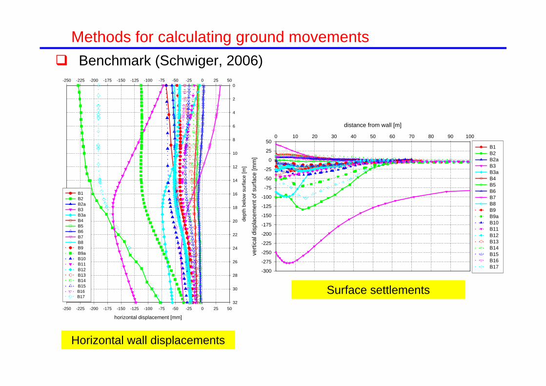
Benchmark (Schwiger, 2006)Methods for calculating ground movements
horizontal displacement [mm]
-250 -225 -200 -175 -150 -125 -100 -75 -50 -25 0 25 50
-250 -225 -200 -175 -150 -125 -100 -75 -50 -25 0 25 50
dept
h be
low
sur
face
[m]
0
2
4
6
8
10
12
14
16
18
20
22
24
26
28
30
32
B1B2B2aB3 B3a B4 B5 B6B7 B8B9B9aB10B11B12 B13 B14B15 B16B17
Horizontal wall displacements
distance from wall [m]
0 10 20 30 40 50 60 70 80 90 100
verti
cal d
ispl
acem
ent o
f sur
face
[mm
]
-300
-275
-250
-225
-200
-175
-150
-125
-100
-75
-50
-25
0
25
50B1 B2 B2a B3 B3a B4 B5 B6 B7 B8 B9 B9a B10 B11 B12 B13 B14 B15 B16 B17
Surface settlements

Esquema de la presentación
Introduction. Generation of ground movements by deep excavations
Empirical methods for estimating ground movements
Methods for calculating ground movements
Procedures for control and reduction of movements
A case history
Excavations with large movements: announcing failure?
Conclusions

Procedures for control and reduction of movements Taking adequate measures, it is possible to minimize movements even
in soft soils A recent example: Shanghai metro
h = 15 – 21 m
FillMedium clay
Soft silty clay
Soft to medium clay
Medium to stiff clay
Stiff silty clay or siltBored pile
Compaction grouting
Level 1
Level 2
Level 3
Level 4
Level 5
Final level
Diaphragmwall
17 - 23 m
h = 15 – 21 m
FillMedium clay
Soft silty clay
Soft to medium clay
Medium to stiff clay
Stiff silty clay or siltBored pile
Compaction grouting
Level 1
Level 2
Level 3
Level 4
Level 5
Final level
Diaphragmwall
17 - 23 m
hd
%max huv
hd
%max huvWong et al. (2005)

Procedures for control and reduction of movements
1. Increase stiffness of the retaining system (wall / bracing)
2. Early installation of bracing (especially the top one)
3. Attention to the contact between bracing and wall
4. Preloading the bracing
5. Avoid overexcavations
6. Embedding the wall in a stiff layer
7. Bracing below the maximum excavation depth
8. Impervious wall and water flow control
9. Compensation / correction grouting?

Increase the stiffness of the retaining system increase wall stiffness (thickness, counterforts) increase bracing system (prop separation, prop stiffness)
System stiffness: (EI)/(ws4) (Clough & O’ Rourke, 1990)Flexibility number: (s5)/(EI) (Addenbrooke et al., 2000)
Clough & O’ Rourke (1990)
Addenbrookeet al. (2000)
based on finite elements calculations(nonlinear model with small strain stiffness)
Procedures for control and reduction of movements

Long (2001) database. Excavations in stiff and medium soils
Maximum lateral wall movement
h < 0.6H
System stiffness does not appear to be a dominant factor in these cases
Influence of system stiffness
Procedures for control and reduction of movements

Maximum lateral movement
h > 0.6H
Low FOS
There appears to be some influence of the system stiffness for low factors fo safety
Procedures for control and reduction of movements
Long (2001) database. Excavations in soft soils
Influence of system stiffness

Early installation of bracing top-down construction
Buen Pastor Cathedral, San Sebastián, Spain
Procedures for control and reduction of movements

Plan viewSection
Early installation of bracing top-down construction
Buen Pastor Cathedral, San Sebastián, Spain
Procedures for control and reduction of movements

Maximum lateral movement Maximum settlement
Buen Pastor
Buen Pastor
Early installation of bracing top-down construction
Buen Pastor Cathedral, San Sebastián, Spain
Procedures for control and reduction of movements

Attention to the contact between bracing and wall
Lisbon Metro Circle Line, Singapore Metro
Procedures for control and reduction of movements
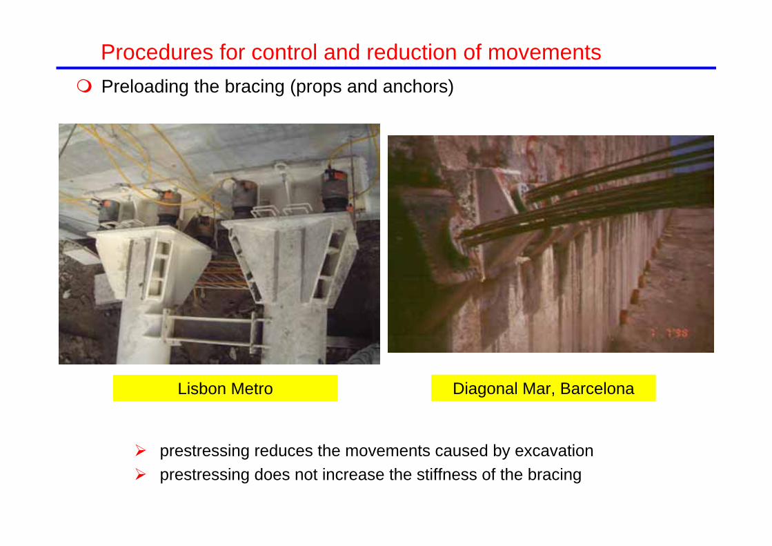
Preloading the bracing (props and anchors)
Lisbon Metro Diagonal Mar, Barcelona
prestressing reduces the movements caused by excavation prestressing does not increase the stiffness of the bracing
Procedures for control and reduction of movements

Preloading of the bracing (props and anchors)
Science Museum, Barcelona
anchors with a considerable free length exhibit a significant deformability
Pile wall (65 cm diameter)
Wall length: 80 m
Max. excavation depth: 20 m
Excavation in weathered granite
Procedures for control and reduction of movements

-10.000 0.000 10.000 20.000 30.000 40.000 50.000 60.000 70.000 80.000 90.000
10.000
20.000
30.000
40.000
50.000
60.000
70.000
Science Museum, Barcelona
-10.000 0.000 10.000 20.000 30.000 40.000 50.000 60.000 70.000 80.000 90.000
10.000
20.000
30.000
40.000
50.000
60.000
70.000
Maximum lateral displacement
Science Museum
Preloading of the bracing (props and anchors) anchors with a considerable free length exhibit a significant deformability
Procedures for control and reduction of movements

Procedures: Props placed in trenches or tunnels previously excavated Rows of barrettes (diaphragm walls segments) Jet grouting slabs or props Slabs of props constructed with deep soil mixing Slabs of props constructed with compaction grouting
For bracing constructed using soil improvement techniques There is no consensus whether it is better to use slabs or thicker
discontinuous props Ground improvement techniques often produce brittle materials that
can lose strength if failure strain is exceeded Constructing the bracing may weaken the overlying soil
Bracing below the maximum excavation depth
Procedures for control and reduction of movements

Props placed in pre-excavated trenches or tunnels
Barbican Arts Centre London
Westminster Station London
Procedures for control and reduction of movements
Bracing below the maximum excavation depth

StudenterlindenOslo
Diaphragm wall segments Lime-cement columns
Procedures for control and reduction of movements
Bracing below the maximum excavation depth

Jet grouting slabs or props
Race Course Road Metro Singapore
Lateral excavation movements in Singapore (Shirlaw, 2006)
No jet grouted slab
Procedures for control and reduction of movements Bracing below the maximum excavation depth

Impervious wall and water flow control The lack of water flow control or the changes in hydraulic conditions
cause sort and long term ground movements
Sealing defects
Pumping
Procedures for control and reduction of movements

Amsterdam. North-South line
Procedures for control and reduction of movements
Vijzelgracht station 250 m long, 22 m wide, 31
m deep Top down construction 1.2 m thick diaphragm
walls 45 m deep 5.1 m long panels with
steel stop ends

Vijzelgracht station, North-South line, Amsterdam Vijzelgracht, 26. Leakage due to a steel stop not being removed
Procedures for control and reduction of movements
(Korff et al., 2009)

Vijzelgracht station, North-South line, Amsterdam Vijzelgracht, 26. Leakage due to a steel stop not being removed
Procedures for control and reduction of movements
(Korff et al., 2009)
Settlement due to ground loss Tilt 1/78 and 1/184. Severe to very severe damage

Vijzelgracht station, North-South line, Amsterdam Vijzelgracht, 4. Leakage due a large bentonite inclusion in the wall
Procedures for control and reduction of movements
(Korff et al., 2009)
Settlement due to ground loss Tilt 1/38 and 1/70. Severe to very severe damage

Compensation grouting Excavation in soft clay in Shanghai (Liu, 2003)
Risk of affecting the wall (injection is performed after the props have been installed)
It is generally counterproductive to perform compensation grouting in soft clays
Procedures for control and reduction of movements

Vijzelgracht station, North-South line, Amsterdam Corrective grouting at Vijzelgracht, 22, 24, 26
Procedures for control and reduction of movements
(Bezuijen et al., 2009)

Vijzelgracht station, North-South line, Amsterdam Corrective grouting at Vijzelgracht, 22, 24, 26
Procedures for control and reduction of movements
(Bezuijen et al., 2009)

Esquema de la presentación
Introduction. Generation of ground movements by deep excavations
Empirical methods for estimating ground movements
Methods for calculating ground movements
Procedures for control and reduction of movements
A case history
Excavations with large movements: announcing failure?
Conclusions

Prat de Llobregat cut-and-cover tunnel
Procedures for control and reduction of movements

Prat de Llobregat cut-and-cover tunnel
Procedures for control and reduction of movements

Prat de Llobregat cut-and-cover tunnel
Procedures for control and reduction of movements

What the papers say…

Inclinometer
Desplazamientos horizontales de la superficie del terrenoen calle M. Bertrand (pk 201+525)
-0.035
-0.030
-0.025
-0.020
-0.015
-0.010
-0.005
0.0000 5 10 15 20 25 30 35 40 45 50 55 60 65 70 75
Distancia al centro de la estructura del IB [m]
Des
plaz
amie
nto
horiz
onta
l [m
]
Computed horizontal displacements
Computed settlements
Desplazamientos verticales de la superficie del terreno en calle M. Bertrand (pk 201+525)
-0.035
-0.030
-0.025
-0.020
-0.015
-0.010
-0.005
0.0000 5 10 15 20 25 30 35 40 45 50 55 60 65 70 75
Distancia al centro de la estructura del IB [m]
Des
plaz
amie
nto
vert
ical
[m]
Relleno
Arenas
Limos y arcillas
Relleno
Arenas
Limos y arcillas
Fill
Sands
Silts and clays
Procedures for control and reduction of movements

Procedures for control and reduction of movements

Desplazamientos horizontales de la superficie del terrenoen calle M. Bertrand (pk 201+525)
-0,035
-0,030
-0,025
-0,020
-0,015
-0,010
-0,005
0,0000 5 10 15 20 25 30 35 40 45 50 55 60 65 70 75
Distancia al centro de la estructura del IB [m]
Des
plaz
amie
nto
horiz
onta
l [m
]
actual
proyecto 0
Desplazamientos verticales de la superficie del terreno en calle M. Bertrand (pk 201+525)
-0,035
-0,030
-0,025
-0,020
-0,015
-0,010
-0,005
0,0000 5 10 15 20 25 30 35 40 45 50 55 60 65 70 75
Distancia al centro de la estructura del IB [m]
Des
plaz
amie
nto
vert
ical
[m]
actual
proyecto 0
Computed settlements
Computed horizontal displacements
Project 0 No additional measures
Procedures for control and reduction of movements

Possible additional measures Increase wall thickness Install additional props Increase wall length Embed the diaphragm wall in a stiff layer Install bracing below the maximum excavation depth (jet grouting)
Cases examined Project 0: No additional measure Project 1: 1.20 m wall thickness (UIC2) Project 2: Project 1 + Temporary intermediate prop Project 3: Project 2 + wall depth to elevation -27 Project 4: Project 2 + wall depth to elevation -34 Project 5: Project 3 + bracing below the maximum excavation depth
Procedures for control and reduction of movements

Desplazamientos verticales de la superficie del terreno en calle M. Bertrand (pk 201+525)
-0,035
-0,030
-0,025
-0,020
-0,015
-0,010
-0,005
0,0000 5 10 15 20 25 30 35 40 45 50 55 60 65 70 75
Distancia al centro de la estructura del IB [m]
Des
plaz
amie
nto
vert
ical
[m]
actual
proyecto 0
proyecto 1
Desplazamientos horizontales de la superficie del terrenoen calle M. Bertrand (pk 201+525)
-0,035
-0,030
-0,025
-0,020
-0,015
-0,010
-0,005
0,0000 5 10 15 20 25 30 35 40 45 50 55 60 65 70 75
Distancia al centro de la estructura del IB [m]
Des
plaz
amie
nto
horiz
onta
l [m
]
actual
proyecto 0
proyecto 1
Computed settlements
Computed horizontal displacements
Project 0 No additional measures
Project 1 Wall thickness:1.2 m
Procedures for control and reduction of movements

Desplazamientos verticales de la superficie del terreno en calle M. Bertrand (pk 201+525)
-0,035
-0,030
-0,025
-0,020
-0,015
-0,010
-0,005
0,0000 5 10 15 20 25 30 35 40 45 50 55 60 65 70 75
Distancia al centro de la estructura del IB [m]
Des
plaz
amie
nto
vert
ical
[m]
actual
proyecto 0
proyecto 1
proyecto 2
Desplazamientos horizontales de la superficie del terrenoen calle M. Bertrand (pk 201+525)
-0,035
-0,030
-0,025
-0,020
-0,015
-0,010
-0,005
0,0000 5 10 15 20 25 30 35 40 45 50 55 60 65 70 75
Distancia al centro de la estructura del IB [m]
Des
plaz
amie
nto
horiz
onta
l [m
]
actual
proyecto 0
proyecto 1
proyecto 2
Computed settlements
Computed horizontal displacements
Project 0 No additional measures
Project 1 Wall thickness: 1.2m
Project 2 Project 1 + additional prop
Procedures for control and reduction of movements

Computed settlements
Computed horizontal displacements
Desplazamientos horizontales de la superficie del terrenoen calle M. Bertrand (pk 201+525)
-0,035
-0,030
-0,025
-0,020
-0,015
-0,010
-0,005
0,0000 5 10 15 20 25 30 35 40 45 50 55 60 65 70 75
Distancia al centro de la estructura del IB [m]
Des
plaz
amie
nto
horiz
onta
l [m
]
actual
proyecto 0
proyecto 1
proyecto 2
proyecto 3
Desplazamientos verticales de la superficie del terreno en calle M. Bertrand (pk 201+525)
-0,035
-0,030
-0,025
-0,020
-0,015
-0,010
-0,005
0,0000 5 10 15 20 25 30 35 40 45 50 55 60 65 70 75
Distancia al centro de la estructura del IB [m]
Des
plaz
amie
nto
vert
ical
[m]
actual
proyecto 0
proyecto 1
proyecto 2
proyecto 3
Project 0 No additional measures
Project 1 Wall thickness: 1.2m
Project 2 Project 1 + additional prop
Project 3 Project 2 + wall to elevation -27
Procedures for control and reduction of movements

Desplazamientos verticales de la superficie del terreno en calle M. Bertrand (pk 201+525)
-0,035
-0,030
-0,025
-0,020
-0,015
-0,010
-0,005
0,0000 5 10 15 20 25 30 35 40 45 50 55 60 65 70 75
Distancia al centro de la estructura del IB [m]
Des
plaz
amie
nto
vert
ical
[m]
actual
proyecto 0
proyecto 1
proyecto 2
proyecto 4
Desplazamientos horizontales de la superficie del terrenoen calle M. Bertrand (pk 201+525)
-0,035
-0,030
-0,025
-0,020
-0,015
-0,010
-0,005
0,0000 5 10 15 20 25 30 35 40 45 50 55 60 65 70 75
Distancia al centro de la estructura del IB [m]
Des
plaz
amie
nto
horiz
onta
l [m
]
actual
proyecto 0
proyecto 1
proyecto 2
proyecto 4
Computed settlements
Computed horizontal displacements
Project 0 No additional measures
Project 1 Wall thickness: 1.2m
Project 2 Project 1 + additional prop
Project 4 Project 2 + wall to elevation -34
Procedures for control and reduction of movements

Project 0 No additional measures
Project 1 Wall thickness: 1.2m
Project 2 Project 1 + additional prop
Project 3 Project 2 + wall to elevation -27
Project 5 Project 3 + Jet grouting prop
Desplazamientos horizontales de la superficie del terrenoen calle M. Bertrand (pk 201+525)
-0,035
-0,030
-0,025
-0,020
-0,015
-0,010
-0,005
0,0000 5 10 15 20 25 30 35 40 45 50 55 60 65 70 75
Distancia al centro de la estructura del IB [m]
Des
plaz
amie
nto
horiz
onta
l [m
]
actual
proyecto 0
proyecto 1
proyecto 2
proyecto 3
proyecto 5
Desplazamientos verticales de la superficie del terreno en calle M. Bertrand (pk 201+525)
-0,035
-0,030
-0,025
-0,020
-0,015
-0,010
-0,005
0,0000 5 10 15 20 25 30 35 40 45 50 55 60 65 70 75
Distancia al centro de la estructura del IB [m]
Des
plaz
amie
nto
vert
ical
[m]
actual
proyecto 0
proyecto 1
proyecto 2
proyecto 3
proyecto 5
Computed settlements
Computed horizontal displacements
Procedures for control and reduction of movements

Trial sections
Procedures for control and reduction of movements

Adopted construction procedure
Procedures for control and reduction of movements

Jet grouting props below maximum excavation depth
Procedures for control and reduction of movements

Fill
Sands
Silts and clays
Finite element model
“Hardening Soil model” for all layers
Procedures for control and reduction of movements

Jet-grouting
-40
-35
-30
-25
-20
-15
-10
-5
0
5
10
-0,020 -0,010 0,000 0,010 0,020
Horizontal displacement (m)
Elev
atio
n (m
)
Observations and model calibration. Ground inclinometers
-40
-35
-30
-25
-20
-15
-10
-5
0
5
10
-0,020 -0,010 0,000 0,010 0,020
Horizontal displacement (m)
Excavation from top to bottom slab
-40
-35
-30
-25
-20
-15
-10
-5
0
5
10
-0,020 -0,010 0,000 0,010 0,020
Horizontal displacement (m)
Elev
atio
n (m
)
Total excavation
Excavation Ground Excavation Ground Excavation Ground
Procedures for control and reduction of movements

Maragall St. section
Procedures for control and reduction of movements

Excavation of first tunnel
Predictions of the calibrated model. Wall inclinometer
Excavation of second tunnel
Total excavation
-40
-35
-30
-25
-20
-15
-10
-5
0
5
10
-0,020 -0,010 0,000 0,010 0,020
Horizontal displacement (m)
Elev
atio
n (m
)
-40
-35
-30
-25
-20
-15
-10
-5
0
5
10
-0,020 -0,010 0,000 0,010 0,020
Horizontal displacement (m)
-40
-35
-30
-25
-20
-15
-10
-5
0
5
10
-0,020 -0,010 0,000 0,010 0,020
Horizontal displacement (m)
Excavation Ground Excavation Ground Excavation Ground
Procedures for control and reduction of movements

Estimation of potential damage
Excavation of the second tunnel
Displacements from phase 7 to phase 16
0.0
0.5
1.0
1.5
2.0
2.5
3.0
3.5
0.000 1.000 2.000 3.000 4.000 5.000 6.000 7.000
Angular distortion (‰)
Hor
izon
tal s
trai
n (‰
)
model M35_0
Severe to very severe
Moderate
Slight
Negligible
Very slight
Procedures for control and reduction of movements

Total excavation
Displacements from phase 0 to phase 16
0.0
0.5
1.0
1.5
2.0
2.5
3.0
3.5
0.000 1.000 2.000 3.000 4.000 5.000 6.000 7.000
Angular distortion (‰)
Hor
izon
tal s
trai
n (‰
)
model M35_1
Severe to very severe
Moderate
Slight
Negligible
Very slight
Estimation of potential damageProcedures for control and reduction of movements

Construction of tunnel UIC
Procedures for control and reduction of movements

7-06-2007 15-10-2007
Procedures for control and reduction of movements
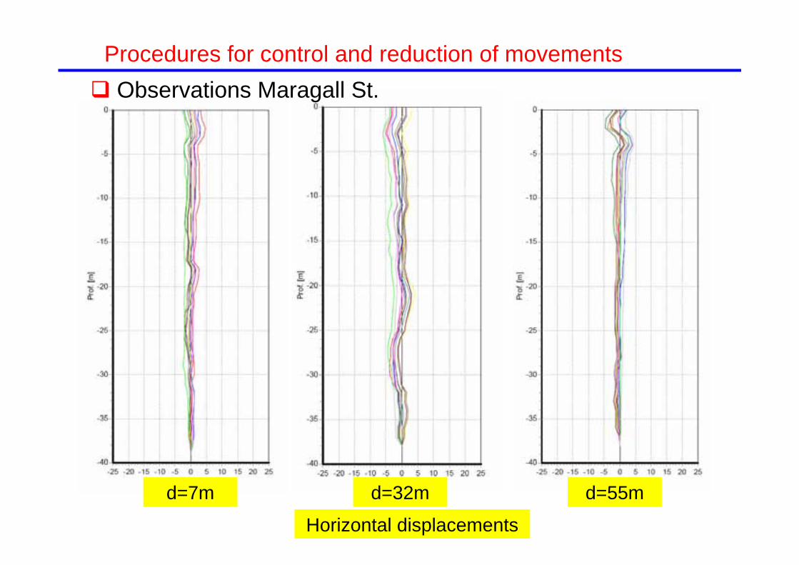
Observations Maragall St.
Horizontal displacements
d=55md=32md=7m
Procedures for control and reduction of movements

Esquema de la presentación
Introduction. Generation of ground movements by deep excavations
Empirical methods for estimating ground movements
Methods for calculating ground movements
Procedures for control and reduction of movements
A case history
Excavations with large movements: announcing failure?
Conclusions
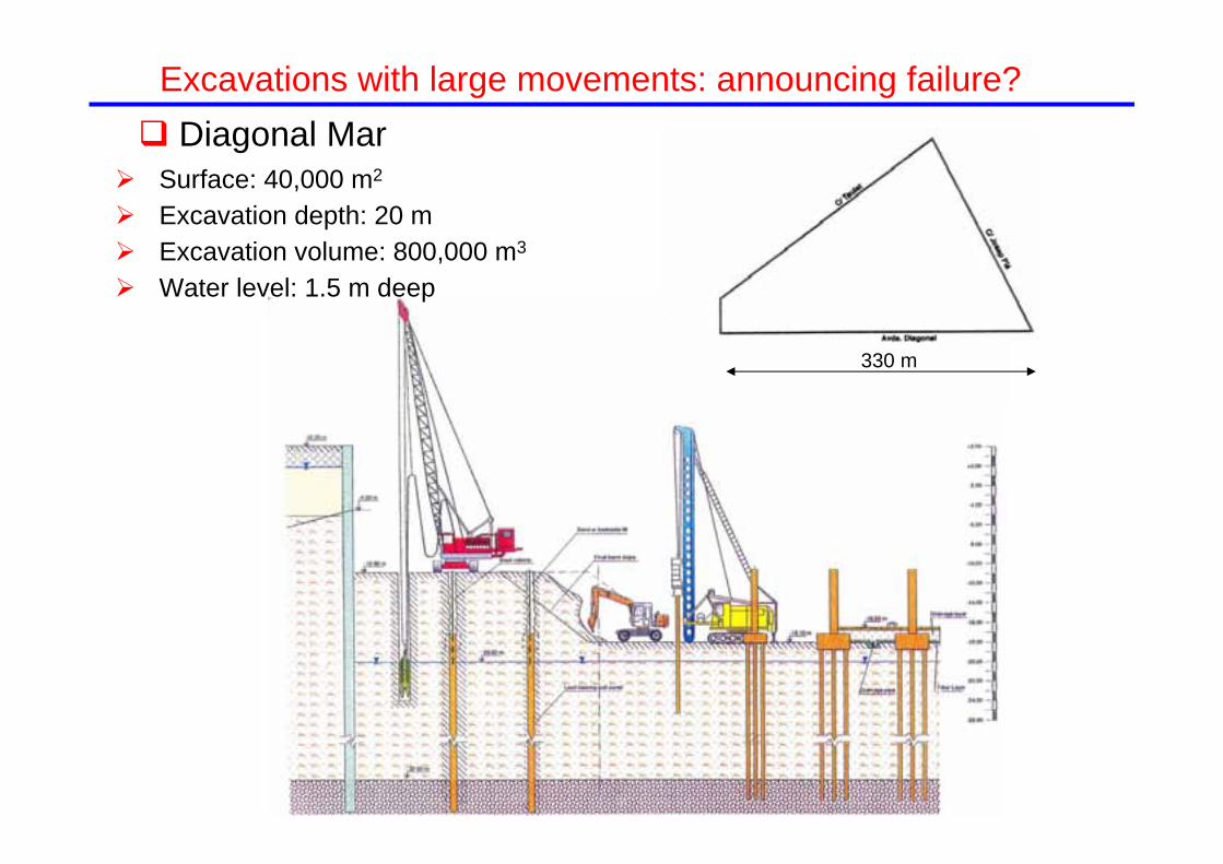
Surface: 40,000 m2
Excavation depth: 20 m Excavation volume: 800,000 m3
Water level: 1.5 m deep
330 m
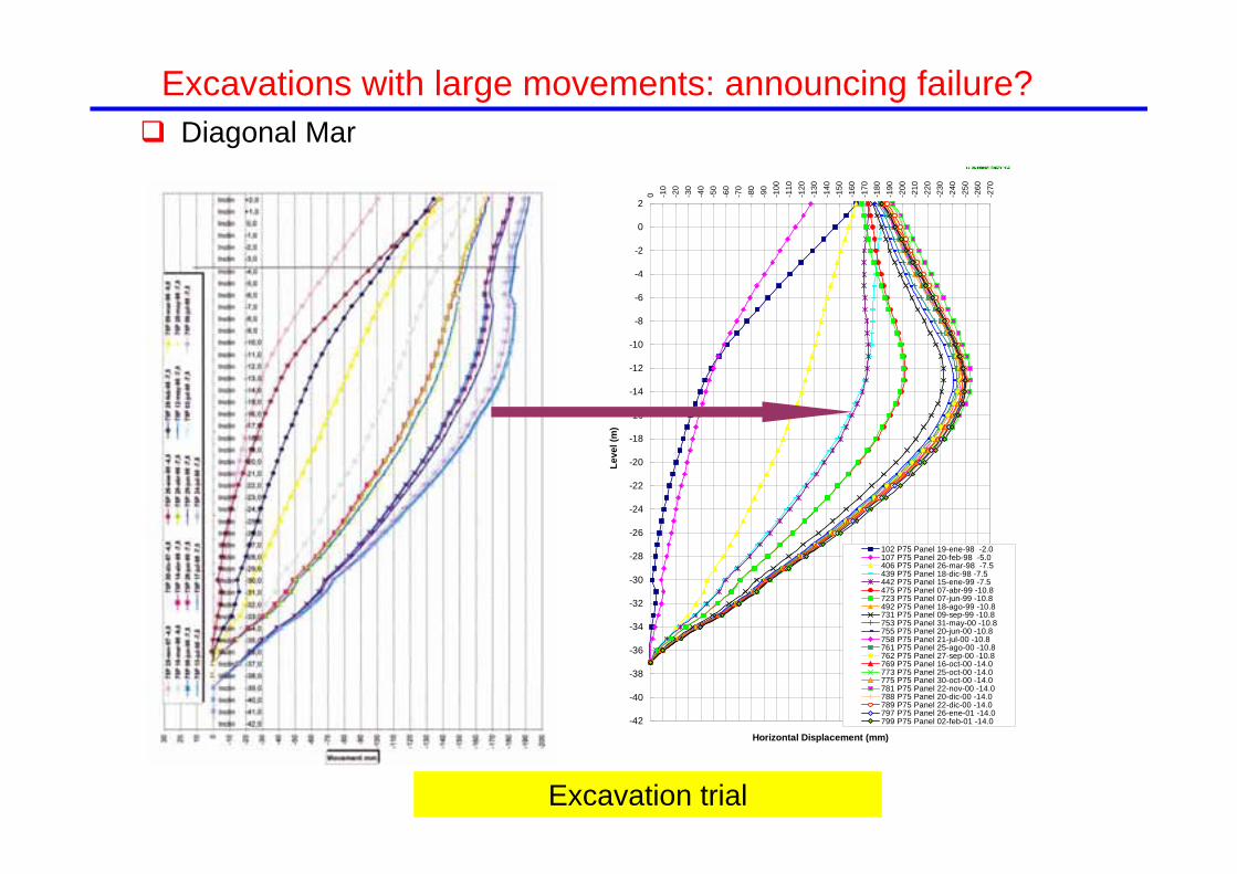
Excavations with large movements: announcing failure? Diagonal Mar

Diagonal MarExcavations with large movements: announcing failure?

Diagonal MarExcavations with large movements: announcing failure?

- 4.50 m
- 7.50 m- 9.00 m
Anchor head
Excavation with 1 anchor
Cantilever excavation to -4.50 m
Wall horizontal displacements
Diagonal MarExcavations with large movements: announcing failure?

-90.000 -60.000 -30.000 0.000 30.000 60.000
-90.000
-60.000
-30.000
0.000
Gravel (lower aquifer)
Still clayey silt
Silty fine sands (intermediate
layer)
Sands (upper aquifer)
Symmetry axis
60 m
Diagonal Mar: numerical modelExcavations with large movements: announcing failure?

Diagonal Mar: calculations and observations
-70
-65
-60
-55
-50
-45
-40
-35
-30
-25
-20
-15
-10
-5
0
5
10
-0.20 -0.15 -0.10 -0.05 0.00 0.05 0.10 0.15 0.20 0.25
Horizontal displacement (m)
Elev
atio
n (m
)
model p75b i75p (04.11.97 to 19.01.98)
Horizontal wall displacements
Cantilever excavation to -4.50 m
-70
-65
-60
-55
-50
-45
-40
-35
-30
-25
-20
-15
-10
-5
0
5
10
-0.20 -0.15 -0.10 -0.05 0.00 0.05 0.10 0.15 0.20 0.25
Horizontal displacement (m)
Elev
atio
n (m
)
model p75b i75p (04.11.97 to 17.07.98)
Anchored excavation to -7.50 m
Excavations with large movements: announcing failure?

Cantilever wall Anchored wall
-50.000 -40.000 -30.000 -20.000 -10.000 0.000 10.000 20.000 30.000 40.000 50.000 60.000
-70.000
-60.000
-50.000
-40.000
-30.000
-20.000
-10.000
0.000
10.000
m
-0.060
-0.040
-0.020
0.000
0.020
0.040
0.060
0.080
0.100
0.120
0.140
0.160
0.180
0.200
-50.000 -40.000 -30.000 -20.000 -10.000 0.000 10.000 20.000 30.000 40.000 50.000 60.000
-70.000
-60.000
-50.000
-40.000
-30.000
-20.000
-10.000
0.000
10.000
m
-0.060
-0.040
-0.020
0.000
0.020
0.040
0.060
0.080
0.100
0.120
0.140
0.160
0.180
0.200
Diagonal Mar: numerical model
Horizontal displacements contours
Excavations with large movements: announcing failure?

Surface crack 35 m away from the wall
Diagonal Mar: field observationsExcavations with large movements: announcing failure?
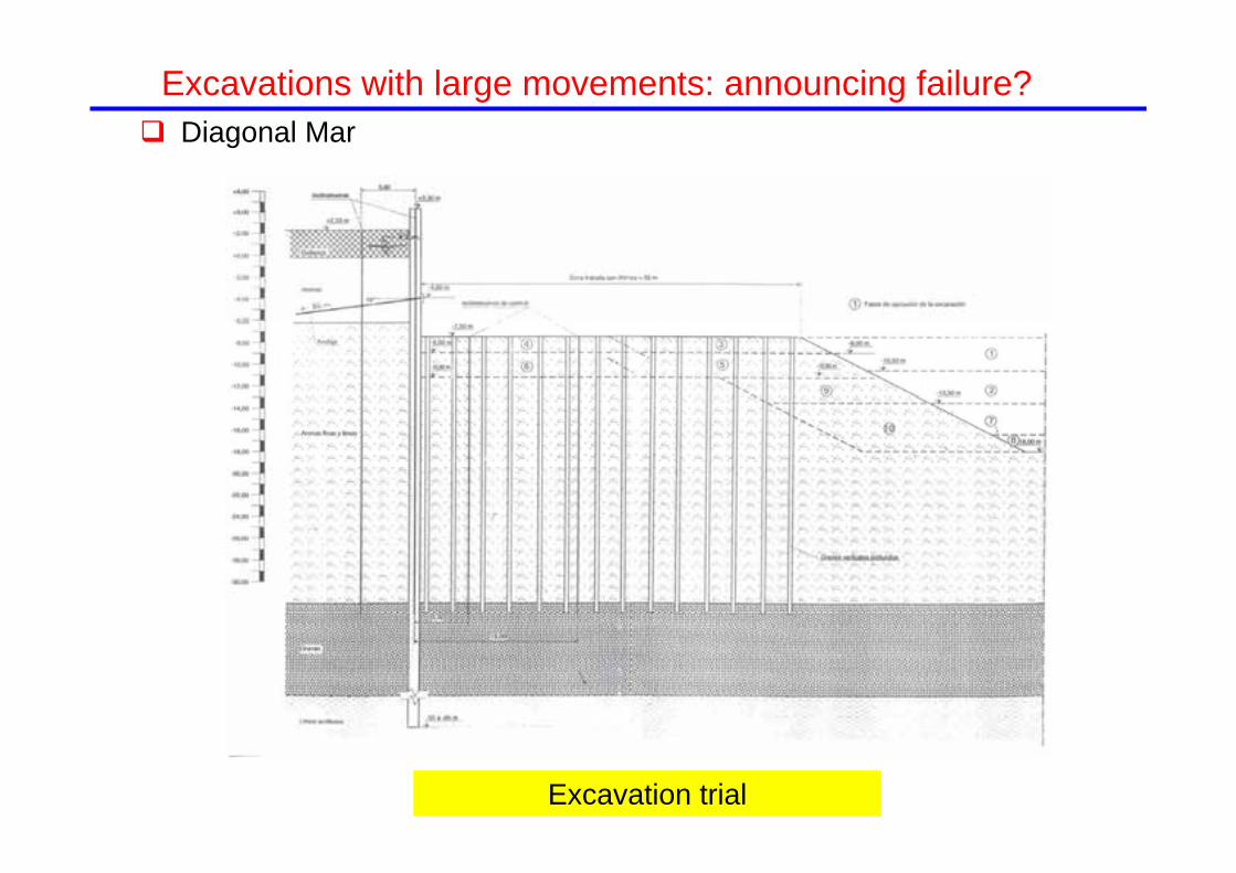
Diagonal Mar
Excavation trial
Excavations with large movements: announcing failure?
Diagonal Mar
-42
-40
-38
-36
-34
-32
-30
-28
-26
-24
-22
-20
-18
-16
-14
-12
-10
-8
-6
-4
-2
0
2
-270
-260
-250
-240
-230
-220
-210
-200
-190
-180
-170
-160
-150
-140
-130
-120
-110
-100
-90
-80
-70
-60
-50
-40
-30
-20
-10
0
Horizontal Displacement (mm)
Leve
l (m
)
102 P75 Panel 19-ene-98 -2.0107 P75 Panel 20-feb-98 -5.0406 P75 Panel 26-mar-98 -7.5439 P75 Panel 18-dic-98 -7.5442 P75 Panel 15-ene-99 -7.5475 P75 Panel 07-abr-99 -10.8723 P75 Panel 07-jun-99 -10.8492 P75 Panel 18-ago-99 -10.8731 P75 Panel 09-sep-99 -10.8753 P75 Panel 31-may-00 -10.8755 P75 Panel 20-jun-00 -10.8758 P75 Panel 21-jul-00 -10.8761 P75 Panel 25-ago-00 -10.8762 P75 Panel 27-sep-00 -10.8769 P75 Panel 16-oct-00 -14.0773 P75 Panel 25-oct-00 -14.0775 P75 Panel 30-oct-00 -14.0781 P75 Panel 22-nov-00 -14.0788 P75 Panel 20-dic-00 -14.0789 P75 Panel 22-dic-00 -14.0797 P75 Panel 26-ene-01 -14.0799 P75 Panel 02-feb-01 -14.0
Excavation trial
Excavations with large movements: announcing failure?

Diagonal Mar: observations and calculations
Anchored excavation to -18.0 m. Horizontal displacements
-50.000 -40.000 -30.000 -20.000 -10.000 0.000 10.000 20.000 30.000 40.000 50.000 60.000
-70.000
-60.000
-50.000
-40.000
-30.000
-20.000
-10.000
0.000
10.000
m
-0.060
-0.040
-0.020
0.000
0.020
0.040
0.060
0.080
0.100
0.120
0.140
0.160
0.180
0.200
-70
-65
-60
-55
-50
-45
-40
-35
-30
-25
-20
-15
-10
-5
0
5
10
-0.20 -0.15 -0.10 -0.05 0.00 0.05 0.10 0.15 0.20 0.25
Horizontal displacement (m)
Elev
atio
n (m
)
model p75b i75p (04.11.97 to 07.04.99)
Excavations with large movements: announcing failure?

Diagonal Mar
Maximum lateral wall displacements
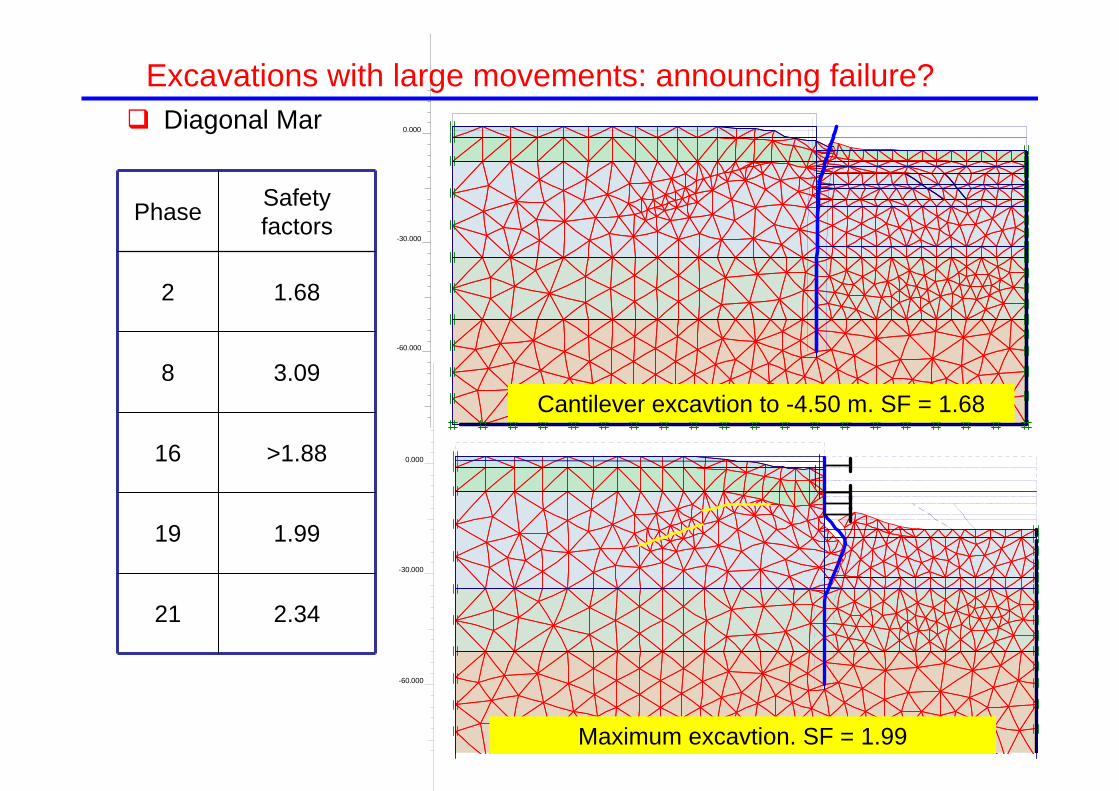
Excavations with large movements: announcing failure?
-60.000
-30.000
0.000 Diagonal Mar
2.3421
1.9919
>1.8816
3.098
1.682
Safety factorsPhase
Cantilever excavtion to -4.50 m. SF = 1.68
-60.000
-30.000
0.000
Maximum excavtion. SF = 1.99
Excavations with large movements: announcing failure?

Diagonal MarExcavations with large movements: announcing failure?

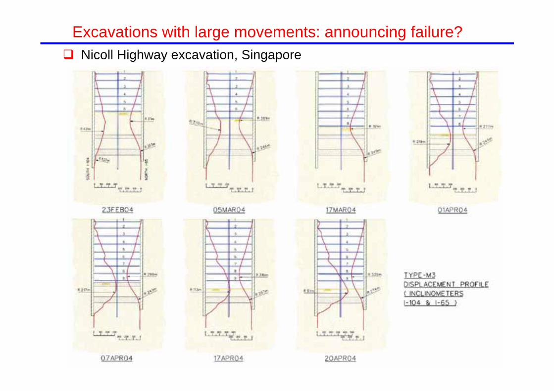
Nicoll Highway excavation, Singapore
20/4/04
Excavations with large movements: announcing failure?

Kalla
ngFo
rmat
ion
Old
Allu
vium
Fill
Nicoll Highway excavation, SingaporeExcavations with large movements: announcing failure?

Nicoll Highway excavation, Singapore
Excavations with large movements: announcing failure?
Nicoll Highway excavation, Singapore
Excavations with large movements: announcing failure?

Nicoll Highway excavation, Singapore
North wall South wall
Excavations with large movements: announcing failure?

Nicoll Highway excavation, Singapore
Maximum lateral wall displacements
North wall
South wall
Excavations with large movements: announcing failure?

9
8
7
6
Nicoll Highway excavation, Singapore
Excavations with large movements: announcing failure?
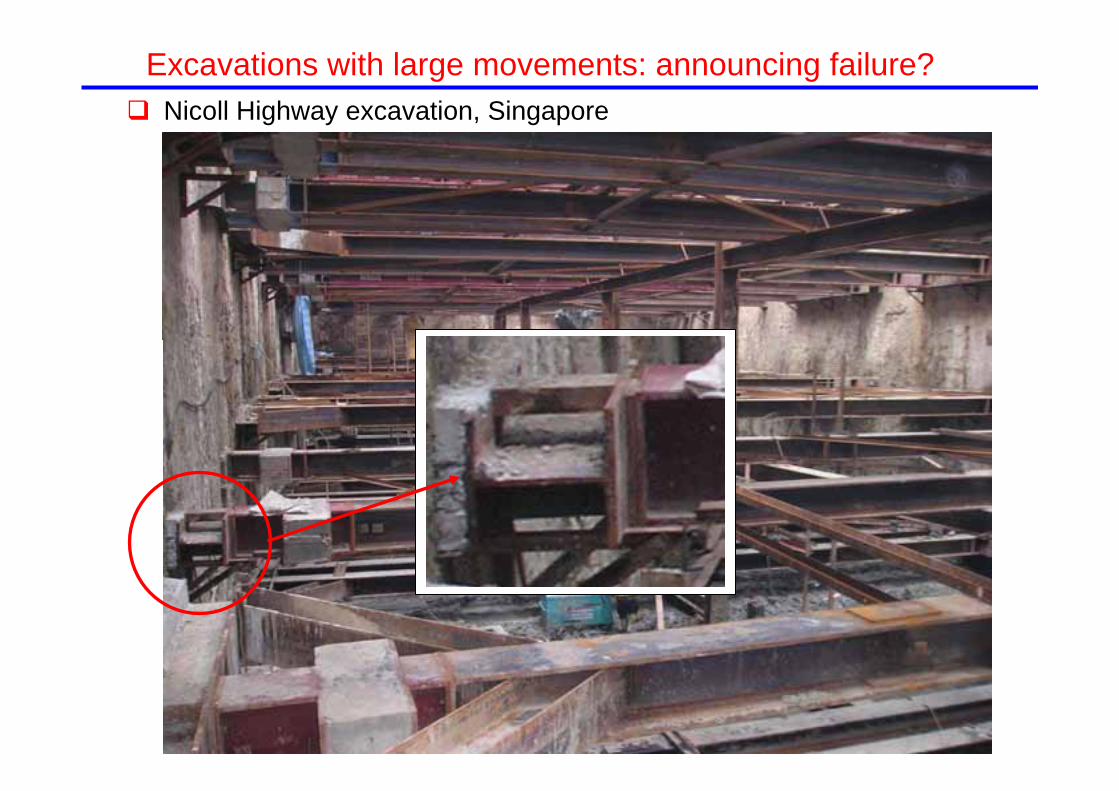
Nicoll Highway excavation, Singapore
Excavations with large movements: announcing failure?

Nicoll Highway excavation, Singapore
Strut 338Strut 338--9 north wall9 north wall
Strut 335Strut 335--9 south wall9 south wall
Excavations with large movements: announcing failure?

Summary & conclusions
Performing a deep excavation inevitably produces movements in the retaining walls and surrounding ground. The tolerance concerning acceptable deformation levels (in urban conditions) has reduced significantly in recent years
The mechanisms of excavation-induced deformations are well identified. Horizontal movements are mainly tension ones, more unfavourable than in the tunnelling case
There exists a wide documented experience providing useful information to estimate excavation-induced ground movements and heir possible effects on nearby structures
Numerical analyses of excavations are becoming widespread. Those methods provide a more complete perspective of the problem but must be validated and calibrated if used for prediction purposes.
There is a large range of construction procedures to reduce the excavation-induced ground movements to the required levels.
Although it is advisable to try to prevent large deformations of the retaining walls, they are not necessarily signs of impending failure.