ground penetrating radar - viy.com.uaviy.com.ua/download/usermanual_en.pdf · viy ® – registered...
TRANSCRIPT

User ManualPart 1. Equipment
VIY®3 Ground Penetrating Radar

© Transient Technologies LLC 2004…2016
Transient Technologies LLC
office 604, 13 Evgena Sverstuka str. Kyiv 02660, UkrainePhone: +380 (44) 240-85-94E-mail: [email protected]: www.viy.ua
VIY® – registered trademark of Transient Technologies LLC
All pictures in this User Manual are given for reference purpose only, and may differ from actual product appearance.
Product design and specification may be changed by manufacturer without notification.
ContentsGeneral information ................................................................................................. 5
General purpose of using VIY3 series GPR ................................................................... 5Application of VIY3 series GPR....................................................................................... 5
Package contents ............................................................................................................. 6VIY3-070 GPR................................................................................................................. 6VIY3-125 GPR................................................................................................................. 6VIY3-300 GPR................................................................................................................. 6VIY3-500 GPR................................................................................................................. 6VIY3-700 GPR................................................................................................................. 7List of Equipment and Accessories ................................................................................. 7
Components Description ......................................................................................... 10VIY3-070 GPR................................................................................................................. 10VIY3-125 GPR................................................................................................................. 10VIY3-300 GPR................................................................................................................. 11VIY3-500 GPR................................................................................................................. 11VIY3-700 GPR................................................................................................................. 11VO-20 Measuring wheel .................................................................................................. 12Cart-36 and Cart-6 Handcarts ......................................................................................... 12Backpack for GPR accessories ....................................................................................... 13
Getting Started .......................................................................................................... 14Connection of push-pull sockets. .................................................................................... 14Connection of VIY3-70 antenna units.............................................................................. 14Connection of VIY3-125, VIY3-300, VIY3-500, and VIY3-700 GPR to laptop ................ 16Wi-Fi connection between GPR and laptop .................................................................... 17Measuring wheel (odometer) VO-20 connection ............................................................. 18Cart-36 Handcart ............................................................................................................. 19VIY3-300 GPR mounting on the Cart-36 Handcart ......................................................... 20VIY3-500 (or VIY3-700) GPR mounting on the Cart-36 Handcart................................... 21Handcart assembly.......................................................................................................... 22Laptop mounting and its connection to GPR .................................................................. 24Mounting the laptop shelf on the operator’s backpack .................................................... 26GPR parameters setting and GPR calibration................................................................. 28
GPR battery charging............................................................................................... 29Charging the battery of VIY3-300 or VIY3-125 GPR ....................................................... 29Charging the battery of VIY3-500 or VIY3-700 GPR ....................................................... 29Charging the batteries of VIY3-070 GPR ....................................................................... 30
GPR battery replacement......................................................................................... 31VIY3-125, and VIY3-300 GPR......................................................................................... 31VIY3-500, and VIY3-700 GPR......................................................................................... 32VIY3-070 GPR................................................................................................................. 32
Specifications ........................................................................................................... 33WiFi Specification ............................................................................................................ 34
Limited Warranty ...................................................................................................... 35


5
General information
General information
General purpose of using VIY3 series GPRGround Penetrating Radar (GPR) is designed for non-destructive sounding and inspecting of different structures and underground objects.
GPR can be applied by geophysicists, construction companies, can be used in different ecological investigations, utilities condition assessment (including both metallic and non-metallic, plastic, concrete, asbestos pipes). Can be used for searching and mapping of: underground water sources leaks, oil and other dangerous liquids underground pollutions; ground water level.
Application of VIY3 series GPRVIY3-070
• Shallow located undersurface geological structure mapping;• Ground water level mapping;• Ice thickness measurement;• Determination of water level thickness and bottom sediments profile mapping;• Location and mapping of seasonal frost penetration areas, and permafrost areas.
VIY3-125
• Shallow located undersurface geological structure mapping;• Ground water level mapping;• Ice thickness measurement;• Determination of water level thickness and bottom sediments profile mapping;• Location and mapping of seasonal frost penetration areas, and permafrost areas.
VIY3-300
• Utilities mapping and detection (pipes, cables);• Civil engineering surveys (building basements, cellars etc.);• Search for buried waste products, and graves;• Mapping and location of near surface voids, karst and other cavities;• Determination of boundaries of petroleum contamination zones etc.
VIY3-500
• Utilities mapping and detection (pipe, cables);• Civil engineering surveys (building basements, cellars etc.);• Archaeology• Determination of boundaries of petroleum contamination zones etc.
VIY3-700
• Civil engineering surveys (roads, bridges);• Search for hidden voids and cracks inside buildings walls, in mine tunnels, car tunnels, concrete
abutments and overhead covers;• Roads structure integrity inspection, takeoff and landing strips;• Archaeology;• Forensic and security investigations.

6
General information
Package contentsVIY3 series GPR can be ordered with different options. The right choice depends on the tasks to be carried out with the help of GPR.
Order information
VIY3-070 GPRTypical VIY3-070 set includes:
• AB3-070t – transmitter antenna unit of 70 MHz with the battery• AB3-070r – receiver antenna unit of 70 MHz with digital output and the battery• Charger – Battery charger• Data Cable 6 – Data cable, 6 meters length• TB-3 – Transport belt• Measuring wheel VO-20• Backpack 2 - the backpack for accessories with the laptop shelf
9 Laptop is not included in the GPR set and may be purchased separately
VIY3-125 GPRTypical VIY3-125 set includes:
• AB3-125 – antenna unit of 125 MHz with digital output and the battery• Charger – Battery charger• Data Cable 3 – Data cable, 3 meters length• TB-3 – Transport belt• Measuring wheel VO-20• Backpack 2 - the backpack for accessories with the laptop shelf
9 Laptop is not included in the GPR set and may be purchased separately
VIY3-300 GPRTypical VIY3-300 set includes:
• AB3-300 – antenna unit of 300 MHz with digital output and the battery • Charger – Battery charger• Data Cable 3 – Data cable, 3 meters length• TB-3 – Transport belt• Measuring wheel VO-20• Backpack 2 - the backpack for accessories with the laptop shelf• SH-300 - Protective bottom cover• * GPR handcart Cart-36
9 Laptop is not included in the GPR set and may be purchased separately
VIY3-500 GPRTypical VIY3-500 set includes:
• AB3-500 – antenna unit of 500 MHz with digital output and the battery• Battery Box – the box for battery • Charger – Battery charger• Data Cable 3 – Data cable, 3 meters length• DP Cable 3 – Connective cable to connect AB3-500 to Battery Box• TB-3 – Transport belt• Measuring wheel VO-20 with adapter A-700• Backpack 1 - the backpack for antenna and accessories, with the laptop shelf
GPR series
Built-In Inclinometer
Built-In WiFi channel
GPR handcartCentral frequency,MHz
V IY3-500iwt

7
General informationGeneral information
• * GPR handcart Cart-36 9 Laptop is not included in the GPR set and may be purchased separately
VIY3-700 GPRTypical VIY3-700 set includes:
• AB3-700 – antenna unit of 700 MHz with digital output and the battery• Battery Box – the box for battery • Charger – Battery charger• Data Cable 3 – Data cable, 3 meters length• DP Cable 3 – Connective cable to connect AB3-500 to Battery Box• TB-3 – Transport belt• Measuring wheel VO-20 with adapter A-700• Backpack 1 - the backpack for antenna and accessories, with the laptop shelf• * GPR handcart Cart-36
9 Laptop is not included in the GPR set and may be purchased separately
* GPR handcart Cart-36 can be included in the GPR set optionally.
See Order information, page 6
List of Equipment and Accessories
Item View Description
AB3-070t AB3-070r
70 MHz frequency antenna units with digital output, batteries included, with optional GPS support and measuring wheel.
Options: Built-in inclinometers Built-in WiFi
AB3-125 125 MHz frequency antenna unit with digital output, battery included, with optional GPS support and measuring wheel.
Options: Built-in inclinometers Built-in WiFi
AB3-300 300 MHz frequency antenna unit with digital output, battery included, with optional GPS support and measuring wheel.
Options: Built-in inclinometers Built-in WiFi GPR handcart Cart-36
AB3-500 500 MHz frequency antenna unit with digital output, battery included, with optional GPS support and measuring wheel.
Options: Built-in inclinometers Built-in WiFi GPR handcart Cart-36
AB3-700 700 MHz frequency antenna unit with digital output, battery included, with optional GPS support and measuring wheel.
Options: Built-in inclinometers Built-in WiFi GPR handcart Cart-36

8
General information
Battery Box Battery box, included in the GPR sets VIY3-500, VIY3-700
SH-300 Protective bottom cover CH-300, compatible with AB3-300 antenna unit. Designed to be used with GPR without Handcarts. Included in VIY3-300 set.
Backpack 1 The backpack for GPR antenna, accessories, laptop, and battery. Included in VIY3-500, VIY3-700 sets.
Backpack 2 The backpack for GPR accessories and laptop. Included in VIY3-070, VIY3-125, VIY3-300 sets.
Laptop holder
Laptop holder, designed for fastening the laptop on the operator’s chest. Included in VIY3-125, VIY3-300, VIY3-500 and VIY3-700 sets.
A-700 Measuring wheel adapter VO-20. Connects VO-20 to AB3-500 or AB3-700 antenna unit.
VO-20 Measuring wheel, designed to measure GPR operator’s path length. Compatible with AB3-125, AB3-300, AB3-500 and AB3-700 antenna units.
Stopper Stopper, that serves for switching of GPR to Wi-Fi mode. Compatible with AB3-070, AB3-125, AB3-300, AB3-500 and AB3-700.
Data Cable 3 Cable (3 m length) to transfer GPR data from AB3-125, AB3-300, AB3-500 or AB3-700 antenna units and laptop. Included in VIY3-125, VIY3-300, VIY3-500 and VIY3-700 sets.
Data Cable 6 Cable (6 m length) to transfer GPR data from AB3-125, AB3-300, AB3-500 or AB3-700 antenna units and laptop. Can be ordered optionally.
DP Cable 3 Cable (3 m length) to transfer GPR data between Battery Box and AB-500 or AB3-700 antenna units. Included in VIY3-500 and VIY3-700 sets.
DP Cable 1 Cable (1 m length) to transfer GPR data between Battery Box and AB-500 or AB3-700 antenna units. Is used with GPR antenna mounted on the Cart-36 or Cart-6 handcarts.

9
General informationGeneral information
Charger Charger for lead acid batteries. Included in VIY3-125, VIY3-300, VIY3-500 and VIY3-700 sets.
Cart-36 GPR handcart with bidirectional measuring wheel. Designed to be used with VIY3-300, VIY3-500 or VIY3-700.
Cart-6 GPR vehicle cart. Designed to be used with VIY3-300, VIY3-500 or VIY3-700 GPR.
TB-3 Transport belt, can be used for pulling antenna unit by operator during sounding process without using the handcart. Included in VIY3-125, VIY3-300, VIY3-500 and VIY3-700 sets.
Synchro3
Planner
Software package for VIY3 GPR sounding process control, and also for processing and visualizing GPR data.
Full software set can be downloaded for free here: http://viy.ua/download/install_VIY_SGPR.zip
10
Components Description
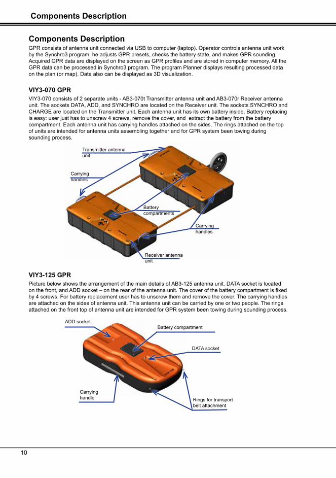
Components DescriptionGPR consists of antenna unit connected via USB to computer (laptop). Operator controls antenna unit work by the Synchro3 program: he adjusts GPR presets, checks the battery state, and makes GPR sounding. Acquired GPR data are displayed on the screen as GPR profiles and are stored in computer memory. All the GPR data can be processed in Synchro3 program. The program Planner displays resulting processed data on the plan (or map). Data also can be displayed as 3D visualization.
VIY3-070 GPRVIY3-070 consists of 2 separate units - AB3-070t Transmitter antenna unit and AB3-070r Receiver antenna unit. The sockets DATA, ADD, and SYNCHRO are located on the Receiver unit. The sockets SYNCHRO and CHARGE are located on the Transmitter unit. Each antenna unit has its own battery inside. Battery replacing is easy: user just has to unscrew 4 screws, remove the cover, and extract the battery from the battery compartment. Each antenna unit has carrying handles attached on the sides. The rings attached on the top of units are intended for antenna units assembling together and for GPR system been towing during sounding process.
VIY3-125 GPRPicture below shows the arrangement of the main details of AB3-125 antenna unit. DATA socket is located on the front, and ADD socket – on the rear of the antenna unit. The cover of the battery compartment is fixed by 4 screws. For battery replacement user has to unscrew them and remove the cover. The carrying handles are attached on the sides of antenna unit. This antenna unit can be carried by one or two people. The rings attached on the front top of antenna unit are intended for GPR system been towing during sounding process.
Receiver antenna unit
Transmitter antenna unit
Carrying handles
Carrying handles
Battery compartments
Battery compartment
Carrying handle
ADD socket
DATA socket
Rings for transport belt attachment

11
Components DescriptionComponents Description
VIY3-300 GPRPicture below shows the arrangement of the main details of AB3-300 antenna unit. The cover of the battery compartment is fixed by 4 screws. For battery replacement user has to unscrew them and remove the cover. The carrying handle is attached on the front of antenna unit.
VIY3-500 GPRPicture below shows the arrangement of the main details of AB3-500 antenna unit. The battery is placed in the separate box to make the antenna unit lighter. DATA socket and EXT socket are located on the top of the battery box. Sockets of antenna unit: ADD socket – on the top front part the unit, EXT socket - on the top back part. EXT socket of antenna unit must be connected to EXT socket of battery box by DP Cable 1. The carrying handle is mounted on the top of the antenna unit. The front screws of handle have rings to attach the transport belt during sounding process.
VIY3-700 GPRPicture below shows the arrangement of the main details of AB3-700 antenna unit. The battery is placed in the separate box to make the antenna unit lighter. DATA socket and EXT socket are located on the top of the battery box. Sockets of antenna unit: ADD socket – on the top front part the unit, EXT socket - on the top back part. EXT socket of antenna unit must be connected to EXT socket of battery box by DP Cable 1. The carrying handle is mounted on the top of the antenna unit. The front screws of handle have rings to attach the transport belt during sounding process.
Carying handle
ADD socket
DATA socket
Rings for transport belt attachment
Battery compartment
Carrying handle
ADD socket
Rings for transport belt attachment DATA socket
EXT socketEXT socket
Carrying handle
ADD socket
Rings for transport belt attachment
DATA socket
EXT socketEXT socket

12
Components Description
VO-20 Measuring wheelVO-20 measuring wheel can be mounted on any antenna unit. It can be mounted to the antenna unit with two screws without using any extra tools.
Measuring wheel can be connected to AB3-700 or AB3-700i antenna unit through A-700 adapter. The adapter can be mounted to antenna units by two screws without using any extra tools.
Cart-36 and Cart-6 HandcartsCart-36 is the Handcart, and Cart-6 is the Vehicle cart. The AB3-300, AB3-500, and AB3-700 antenna units can be mounted on both Cart-36 or Cart-6. The AB3-300 antenna unit should be mounted on the cart using the same mounting bores as for measuring wheel mounting, located at the rear side of antenna unit. The AB3-500 (or AB3-700) should be fixed to the center of the cart with cart belt. The battery box should be fixed to the rear side of the cart with two screws. The measuring wheel is included in the cart design and its cable should be connected to ADD socket of the antenna unit. Example of the AB3-300, AB3-500 (AB3-700) mounting is shown on the pictures below.

13
Components DescriptionComponents Description
Backpack for GPR accessoriesThe backpack is included in each GPR set.
VIY3-070, VIY3-125,and VIY3-300 GPR have Backpack 2 (on the picture above), that serves for:
• GPR accessories storage and transportation (cables, charger, transport belt etc.)• Odometer VO-20 storage and transportation• User laptop storage and transportation• Laptop holder fastening
VIY3-500, and VIY3-700 GPR have Backpack 1 (on the picture below), that serves for:
• AB3-500 or AB3-700 antenna unit storage and transportation• GPR accessories storage and transportation (cables, charger, transport belt etc.)• Odometer VO-20 storage and transportation• Battery Box storage and transportation• User laptop storage and transportation• Laptop holder fastening

14
Getting Started
Getting Started
Connection of push-pull sockets.To connect push-pull sockets match together the red points marked on the plug and socket ends and insert the plug holding its housing. For sockets disconnection just pull the plug ring back and disconnect it.
Connection of VIY3-70 antenna units.Mount the measuring wheel to AB3-070t Transmitter antenna unit with mounting screws of measuring wheel. Connect the measuring wheel cable to ADD socket on the Receiver antenna unit. Connect the DATA socket on the Receiver antenna unit with USB port on the laptop using Data Cable 3. Connect the Synchro socket on Transmitter antenna unit with the Synchro socket on Receiver antenna unit.
From Odometer VO-20 to ADD socket of Receiver unit
From Synchro socket of Transmitter antenna unit to Synchro socket of Receiver antenna unit
Transmitter unit AB3-070t

15
Getting StartedGetting Started
9 Antenna unit power suply is turning on when connecting of Data Cable to DATA socket
From DATA socket of Receiver antenna unit to USB port of laptop
From measuring wheel to ADD socket of the Receiver antenna unit
From Synchro socket of Receiver antenna unit to the Synchro socket of Transmitter antenna unit
From measuring wheel to ADD socket of the Receiver antenna unit
Receiver antenna unit AB3-070r
16
Getting Started
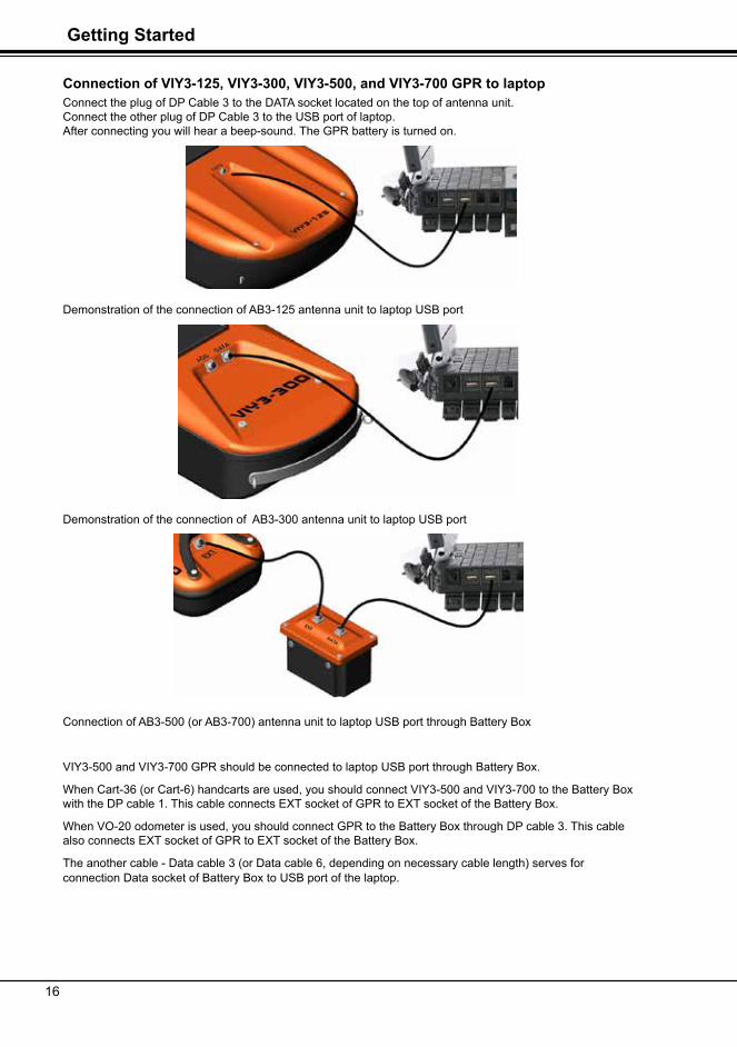
Connection of VIY3-125, VIY3-300, VIY3-500, and VIY3-700 GPR to laptopConnect the plug of DP Cable 3 to the DATA socket located on the top of antenna unit. Connect the other plug of DP Cable 3 to the USB port of laptop. After connecting you will hear a beep-sound. The GPR battery is turned on.
Demonstration of the connection of AB3-125 antenna unit to laptop USB port
Demonstration of the connection of AB3-300 antenna unit to laptop USB port
Connection of AB3-500 (or AB3-700) antenna unit to laptop USB port through Battery Box
VIY3-500 and VIY3-700 GPR should be connected to laptop USB port through Battery Box.
When Cart-36 (or Cart-6) handcarts are used, you should connect VIY3-500 and VIY3-700 to the Battery Box with the DP cable 1. This cable connects EXT socket of GPR to EXT socket of the Battery Box.
When VO-20 odometer is used, you should connect GPR to the Battery Box through DP cable 3. This cable also connects EXT socket of GPR to EXT socket of the Battery Box.
The another cable - Data cable 3 (or Data cable 6, depending on necessary cable length) serves for connection Data socket of Battery Box to USB port of the laptop.

17
Getting StartedGetting Started
Wi-Fi connection between GPR and laptopAntenna units that have ‘w‘ letter in their name, include Wi-Fi equipment for wireless connection to laptop.
To switch VIY3-070, VIY3-125, and VIY3-300 GPR to Wi-Fi mode, connect the stopper to DATA socket on antenna unit. The stopper is included in each GPR set that has Wi-Fi option.
9 The way of connecting of the stopper is similar to push-pull sockets connection (page 14).
To switch VIY3-500 and VIY3-700 GPR to Wi-Fi mode, connect the stopper to DATA socket on Battery Box.The stopper is included in each GPR set that has Wi-Fi option.
Detailed description of the connection of GPR to laptop through Wi-Fi you can find in User Manual part 2. Software
Stopper
Stopper

18
Getting Started
Measuring wheel (odometer) VO-20 connectionMount VO-20 to the rear side of antenna unit with screws, and connect odometer cable plug to ADD socket located on the top of antenna unit.
Demonstration of VO-20 odometer connection to AB3-125 (to ADD socket)
Demonstration of VO-20 odometer connection to AB3-300 (to ADD socket)
Demonstration of VO-20 odometer connection to AB3-700 or AB3-700 (to ADD socket)
9 Connecting VO-20 odometer to AB3-700 or AB3-700 please make sure that odometer sen-sor (its location shown on the picture above) is located from the right side of antenna unit as shown on the picture.
Mount the measuring wheel on the antenna unit with screws
Mount the measuring wheel on the antenna unit with screws
Odometer sensor
19
Getting StartedGetting Started
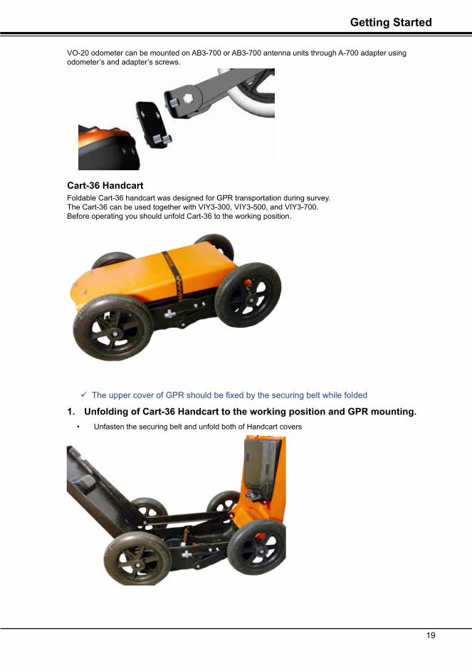
VO-20 odometer can be mounted on AB3-700 or AB3-700 antenna units through A-700 adapter using odometer’s and adapter’s screws.
Cart-36 HandcartFoldable Cart-36 handcart was designed for GPR transportation during survey. The Cart-36 can be used together with VIY3-300, VIY3-500, and VIY3-700. Before operating you should unfold Cart-36 to the working position.
9 The upper cover of GPR should be fixed by the securing belt while folded
1. Unfolding of Cart-36 Handcart to the working position and GPR mounting.• Unfasten the securing belt and unfold both of Handcart covers

20
Getting Started
VIY3-300 GPR mounting on the Cart-36 Handcart• Mount AB3-300 antenna unit into the open Handcart the way as shown on the picture below.
• Fasten the GPR case to the Handcart bottom by securing belt. Also fix GPR to the handcart by two screws as shown on the picture below
fix AB3-300 antenna unit by 2 screws in these places
• Unplug the odometer socket from the socket holder on the Handcart side (see picture below) and connect the socket to ADD socket located on the top of antenna unit.
• Connection GPR to the laptop. Please see pages 14-17
socket holder

21
Getting StartedGetting Started
VIY3-500 (or VIY3-700) GPR mounting on the Cart-36 Handcart
• Mount VIY3-500 GPR (or VIY3-700) as shown on the picture above.
• Fasten the GPR unit to the bottom of Handcart by securing belt.
• Mount the Battery Box into the Handcart as shown on the picture below, and fix it to the handcart by two screws.
• Connect the odometer socket to ADD socket of GPR as presented on the picture.

2322
Getting Started
• Connect one socket of short DP Cable 1 (included in the GPR set, located in the backpack) to EXT socket of Battery Box and other cable socket - to EXT socket of GPR.
• Connect the socket of Data Cable 3 to DATA socket on the top of Battery Box
Handcart assembly• Unfold the upper orange cover of the Handcart and fix it by two screws to the adjacent cover as
shown on the picture below.

2322
Getting StartedGetting Started
• Fix the upper orange cover above the black one by two screws (see picture below).
9 To facilitate matching of the orange cover screws and holes in the black cover, you should use guiding screw located inside the orange cover (see picture below)

2524
Getting Started
• Unfold the black shelf for laptop and fix it by the screw.
Laptop mounting and its connection to GPR • Mount your laptop on the shelf and fix it on it with Velcro tape (included in GPR set).
Stick the Velcro tape on the Handcart shelf and on the laptop bottom in some places.
• Connect socket of Data Cable 3 to USB port of your laptop.
9Wrap the Data Cable 3 around the handle of the cart to avoid undesired loose cable (that could lead to possible additional interferences during sounding process).

2524
Getting StartedGetting Started
2. Folding of the Handcart to the transport position.
Folding of the Handcart to the transport position can be done in the inverse way to the described above.
9 You can leave the GPR inside the Handcart when it is folded. In that case you should disconnect all the sockets from the antenna unit and you should mandatory (!) fasten the odometer socket to the socket holder on the side of the Handcart. Fasten the odometer cable to the metallic support (shown on the picture).
9 The above-mentioned fastening of odometer socket to the socket holder is also manda-tory in the case of empty Handcart folding. The odometer cable must been fastened to the metallic support (shown on the picture).
mettalic supportsocket holder

2726
Getting Started
Mounting the laptop shelf on the operator’s backpackIf GPR is used together with VO-20 odometer, the laptop should be mounted on the special portable shelf that should be fastened to the operator’s backpack.
To mount the laptop shelf follow the next steps:• Take the laptop folder out of the backpack.
• Stick the Velcro tape on the top of Handcart shelf and on the laptop bottom in some places (the Velcro tape is included in GPR set).
• Turn the shelf over and pull out the metallic holders (in direction shown by an arrow below).

2726
Getting StartedGetting Started
• Turn the metallic holders 90 degree aside and put them into slots as shown on the picture below.
• Put the backpack on, adjust the backpack side stripes and fasten the backpack belt.
• Fasten operator’s shelf locks to the corresponding locks on the backpack stripes
• Tuck he lower holders of the shelf behind the operator’s backpack belt.
slots

2928
Getting Started
• Mount the laptop on the shelf, fastening it on the shelf with Velcro tape.
When the work is finished, fold the shelf in the back order and pack it to the backpack.
GPR parameters setting and GPR calibrationPlease read User Manual part 2. Software to find instructions about setting up all the main GPR parameters, its calibration and directions of using Synchro and Planner software.

2928
GPR battery chargingGetting Started
GPR battery chargingEach antenna unit is equipped with the sealed lead acid rechargeable battery (12 V, 7 Ah). The power supply of the antenna unit prevents the deep discharge of the battery. The battery charge level is indicated in the Status bar of the Main window of the Synchro3 software the battery.
When the battery voltage is low and close to the critical value, the power supply begins beeping. When the battery voltage is below the cut-off threshold (10.8V) the power supply will turn the antenna unit off but beep sound will continue ringing twice per second. That indicates the normal state of GPR and the necessity of battery charging. For battery charging use the charger that is included in GPR set.
Charging the battery of VIY3-300 or VIY3-125 GPRFor charging the battery of VIY3-300 or VIY3-125 GPR you should connect the charger plug to the GPR DATA socket, and then plug the charger to the AC power (220-240V AC, 50-60 Hz).
9 To get more information please read the charger User manual that is in the charger set.
Charging the battery of VIY3-500 or VIY3-700 GPRFor charging the battery of VIY3-500 or VIY3-700 GPR you should connect the charger plug to the DATA socket, located on the cover of Battery Box. Then plug the charger to the AC power (220-240V AC, 50-60 Hz).
9 To get more information please read the charger User manual that is in the charger set.

3130
GPR battery charging
Charging the batteries of VIY3-070 GPRWhen using of VIY3-070 GPR you should separately charge the batteries of AB3-070t Transmitter antenna unit, and AB3-070r Receiver antenna unit.
For charging the battery of the Transmitter antenna unit AB3-070t (shown on the right of the picture) you should connect the charger plug to the GPR Charge socket, and then plug the charger to the AC power (220-240 VAC, 50-60 Hz). For charging the battery of the Receiver antenna unit AB3-070r (shown on the left of the picture) you should connect the charger plug to the GPR DATA socket, and then plug the charger to the AC power (220-240 VAC, 50-60 Hz).
9 To get more information please read the charger User manual that is in the charger set.
Transmitter antenna unit AB3-070t
Receiver antenna unit AB3-070r
Connection of the charger socket
3130
GPR battery replacementGPR battery charging
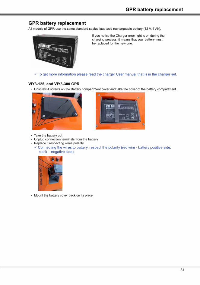
GPR battery replacementAll models of GPR use the same standard sealed lead acid rechargeable battery (12 V, 7 Ah).
9 To get more information please read the charger User manual that is in the charger set.
VIY3-125, and VIY3-300 GPR• Unscrew 4 screws on the Battery compartment cover and take the cover of the battery compartment.
• Take the battery out• Unplug connection terminals from the battery• Replace it respecting wires polarity
9 Connecting the wires to battery, respect the polarity (red wire - battery positive side, black – negative side).
• Mount the battery cover back on its place.
If you notice the Charger error light is on during the charging process, it means that your battery must be replaced for the new one.

3332
GPR battery replacement
VIY3-500, and VIY3-700 GPR• Unscrew 4 screws on the Battery Box cover• Take the battery out• Unplug connection terminals from the battery• Replace it respecting wires polarity
9 Connecting the wires to battery, respect the polarity (red wire - battery positive side, black – negative side).
• Mount the battery cover back on its place..
VIY3-070 GPR• Unscrew 4 screws on the Battery compartment of Transmitter antenna unit AB3-070t and Receiver
antenna unit AB3-070r. See the pictures below.
• Take the battery out• Unplug connection terminals from the battery• Replace it respecting wires polarity
9 Connecting the wires to battery, respect the polarity (red wire - battery positive side, black – negative side).
• Mount the battery cover back on its place.
Receiver antenna unit AB3-070r Transmitter antenna unit AB3-070t

3332
SpecificationsGPR battery replacement
SpecificationsModel of GPR VIY3-070 VIY3-125 VIY3-300 VIY3-500 VIY3-700
Antenna frequency, MHz:
70 125 300 500 700
ADC, bits: 18
Dynamic range,dB: more than 135 dB
Data acquisition rate: up to 146 traces /sec*
Survey window,ns: 240, 360, 480,600 120, 180, 240, 300
66, 100, 133, 166
32, 50, 64, 80 16, 24, 32, 40
Samples per trace: up to 1 000 000
Trace Stacking: up to 128
Maximum depth of sounding (depended by medium properties), m:
35 15 8 4 2,5
Spatial resolution,m: 1,5 1,0 0,3 0,18 0,12
Trigger mode: Single, Internal, External
File size of single profile:
up to 1 000 000 traces
Interface: USB2 or WiFi
Continuous operation time,hours:
more than 4 more than 8
Dimensions,mm: 1207х607х308 1207х607х308
1105х580х232 610х312х170 325х210х156 325х210х156
Weight,kg: 2 * 40 25 9,0 2,5 2,5
Operating temperature:
-20°С ... +40°С
* Data acquisition rate depends on samples per trace and trace stacking.

3534
Specifications
VO-20 Cart-36 Cart-6
Odometer wheel step, mm:
31* 26,54* 159,24*
Cable length, m: 0,3 0,3 0,3
Weight, kg: 0,7 12,8 8,5
Operating dimensions, mm
240х140х200 1000х500х970 1580х500х320
Transport dimensions, mm
845х500х320 845х500х320
Operating temperature:
-20°С ...40°С
* The odometer wheel step is indicated on the nameplate on the VO-20 or Cart-36, Cart-6.
9 Design and specification are subject to change without prior notice.
WiFi SpecificationBuild-in 2.4-GHz IEEE 802.11b/g transceiver
EMC Compliance Information
Specification ComplianceFCC ID U3O-G2M5477 Part 15.247
IC (Canada) RSS-210
CE EU ID # 0681
REG U9M20901-1000-C
RADIO EN 300328 V1.7.1 (10/2006)
EMC EN 301489-1 V1.8.1 (04/2008), EN 301489-17 V1.3.2 (04/2008)
SAFETY EN 60950-1:2001+A11:2004

3534
Limited WarrantySpecifications
Limited WarrantyWarranty. Transient Technologies warrants the enclosed hardware products to be free from defects in material and workmanship for a period of twelve months from the date of original retail purchase. Transient Technologies warrants the enclosed user manuals are delivered to be free from physical defects for a period for twelve months form the date retail purchase.
Repair Procedures, Exclusive Remedy. Transient Technologies will, at its option, repair or replace products not conforming to this limited warranty at no charge. This is the sole and exclusive remedy available for breach of warranty or under any other legal theory with respect to Transient Technologies product. If you find a product to be defective, contact your authorized Transient Technologies representative or Transient Technologies. When you receive authorization, return the product as directed, including proof of purchase and date, at your expense and risk. Product repairs not covered by warranty, and product updates, will be provided at a set rate.
Limitations. This warranty is avoid if the product is damaged by importer or abnormal use or by accident, if the product is altered or modified in any way, or if any attempt is made to repair the product without authorization from Transient Technologies. It is solely the purchaser’s responsibility to determine the suitability of these products for each particular application. Transient Technologies products are in all events not suitable, and are not authorized, for use with systems potentially injurious to life or health. This warranty is not assignable.
No Other Warranties. EXCEPT AS PROVIDED IN THIS LIMITED WARRANTY. TRANSIENT TECHNOLOGIES HARDWARE AND USERMANUAL ARE PROVIDED ‘AS IS’. ALL OTHER WARRANTIES AND REPRESENTATIONS, ORAL OR WRITTEN, EXPRESS OR IMPLIED, INCLUDING BUT NOT LIMITED TO ANY IMPLIED WARRANTIES OF MERCHANTABILITY OR FITNESS FOR A PARTICULAR PURPOSE, ARE EXCLUDED AND DO NOT APPLY, THERE ARE NO WARRANTIES WICH EXTEND BEYOND THE DESCRIPTION OF THE FACE HEREOF. Except as required by law, no representative, agent, or employee Transient Technologies is authorized to make warranties, representations, or obligations inconsistent with or in addition to those set forth in this limited warranty.
TRANSIENT TECHNOLOGIES DOES NOT WARRANT FOR THE CONTENTS AND SERVICES OTHER SITES, WHICH YOU MAY ACCESS FROM HYPERLINKS ON TRANSIENT TECHNOLOGIES WEBSITES, TRANSIENT TECHNOLOGIES INSTALLATION CD OR ANY MATERIAL. No Damages. IN NO EVENT WILL TRANSIENT TECHNOLOGIES BE LIABLE FOR DIRECT, INDIRECT, SPECIAL, INCIDENTIAL, OR CONSEQUENTIAL, DAMAGES RESULTING FROM ANY BREACH OF WARRANTY OR UNDER ANY OTHER THEORY, even if advised of the possibility of such damages. In event Transient Technologies be liable for sums in excess of the purchase price of the product. Transient Technologies is thus not liable for lost profits or goodwill; downtime; damage or destruction of any program, data, equipment, or other property; cost of recovering, reprogramming, or reproducing any program, data, or equipment; personal injury or loss; or any other damages.
General. This agreement is the entire agreement between you and Transient Technologies; supersedes any prior or different agreements, representations, or proposals; and may be changed only by written agreement with Transient Technologies. Waiver by any default or breach of this agreement will not constitute a waiver of any subsequent default or breach of the same or different kind. The invalidity of any provision of this agreement shall not affect the validity of the other provisions hereof.