ground start implementation with silicon …
TRANSCRIPT
Rev. 0.1 10/06 Copyright © 2006 by Silicon Laboratories AN30
AN30
GROUND START IMPLEMENTATION WITH SILICON LABORATORIES ’ DAAS
1. Background
The Silicon Laboratories’ direct access arrangement (DAA) products are designed as a telecommunication interface that rely on “loop-start signaling.” This is the predominant method of signaling between a customer installation (CI) and a central office (CO). For this method of signaling the CO provides a battery voltage between TIP and RING. The CI requests service (line seizure) by reducing the TIP-to-RING resistance. The CO senses the DC current in the loop and determines the CI is in an off-hook state, thus the term “loop-start.”
An alternative to loop-start signaling is to use ground-start signaling. This method of signaling is typically used in private branch exchange (PBX) to central office (CO) lines. Ground-start lines are used in lieu of loop-start lines in these applications primarily because it reduces the time interval during which the line can be seized from either end. A simultaneous seizure of the line by both ends is called “glaring.” The details of ground-start signaling are specified in chapter 6 of ANSI T1.401-1993.
2. PBX Seizure
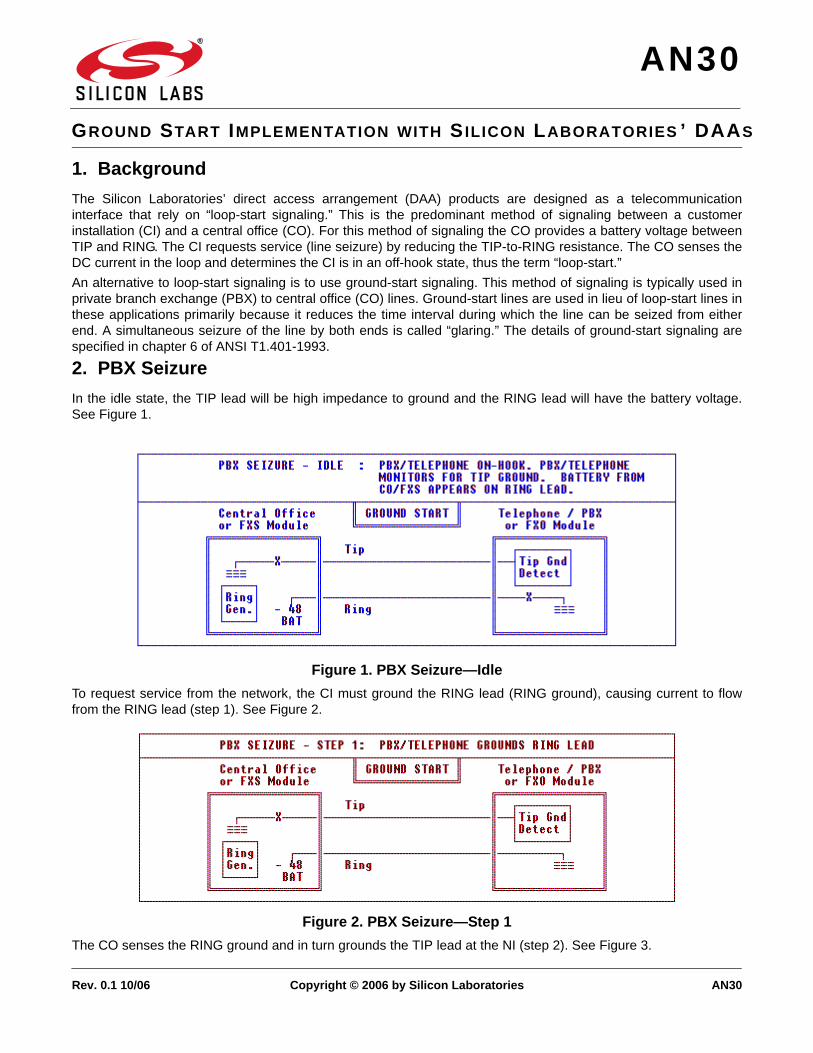
In the idle state, the TIP lead will be high impedance to ground and the RING lead will have the battery voltage. See Figure 1.
Figure 1. PBX Seizure—Idle
To request service from the network, the CI must ground the RING lead (RING ground), causing current to flow from the RING lead (step 1). See Figure 2.
Figure 2. PBX Seizure—Step 1
The CO senses the RING ground and in turn grounds the TIP lead at the NI (step 2). See Figure 3.

AN30
2 Rev. 0.1
Figure 3. PBX Seizure—Step 2
When the CI senses the TIP ground reply from the CO, it must close the loop and remove the RING ground. The call then continues as in loop-start (step 3). See Figure 4.
Figure 4. PBX Seizure—Step 3
3. CO Seizure
The procedure for a call into the CI is very similar. The CO initiates the signaling by grounding the TIP lead to the CI (step 1). See Figure 5.
Figure 5. CO/FXS Seizure—Step 1
When the CI detects the TIP ground, it must close the loop (step 2). While the TIP is grounded, some networks will present a ring signal to the line. From the point in which the CI closes the loop, the call continues as in a loop-start

AN30
Rev. 0.1 3
system. See Figure 6.
Figure 6. CO/FXS Seizure—Step 2
4. Far-End Disconnect
Ground-start signaling also allows for a reliable detection of the far end disconnecting the call. When a call is completed, both loop-start and ground-start systems return the line to the idle state. However, in ground-start systems the CO can end the call by opening the TIP ground connection (step 1), thus the CI will “know” the other end disconnected because loop current will cease to flow (step 2). See Figure 7 and Figure 8.
Figure 7. Far-End Disconnect—Step 1

AN30
4 Rev. 0.1
Figure 8. Far-End Disconnect—Step 2
5. Silicon Laboratories’ DAAs
With the addition of relays, a voltage or current supply, and a current sensing circuit, the Silicon Labs’ DAAs can be used in systems that require ground-start signaling. Figure 9 shows the necessary connections.
A relay with a resistor to ground on the RING lead and a relay, supply, and current sensing circuit on the TIP lead are needed. A simple single pole, single throw relay is sufficient for both the “RING GROUND” and “TIP SENSE” relays shown in Figure 9. The resistor (R) may be a maximum of 550 and should have sufficient capability to handle 120 mA and 50 V. The current sense circuit is beyond the scope of this application note. This circuit, with the supply, must be able to sense when the TIP lead is grounded at the CO and be able to signal to the CI to close the loop for service.
The “RING GROUND” relay is necessary for the CI to signal to the CO the desire to use the line. To initiate a call, the CI should close the “RING GROUND” relay, and wait for current to flow through the current sensing circuit (which is already closed form the idle state). When this occurs, the DAA should be taken off-hook for the call and both the “TIP SENSE” and “RING GROUND” relays should be opened. At the completion of the call, the loop current will stop, and the “TIP SENSE” relay should be closed to return to the idle state.
During the idle state, the “TIP SENSE” relay should remain closed. When the CO grounds the TIP lead, current will begin to flow through the sensing circuit and the DAA should be taken off-hook. After the DAA has closed the loop, the “TIP SENSE” relay may be opened to avoid interference on the line, but this relay must be closed after the call is completed in order to return to the idle state.

AN30
Rev. 0.1 5
Figure 9. Connections
6. Conclusion
The advantages of ground-start signaling include minimizing the possibility of glare and reliable far-end disconnection detection. The disadvantages are that the TIP/RING polarity is fixed and the CO and CI grounds must be nearly at the same potential. There is limited support for ground-start signaling in most PBXs, but with minor additions to the typical application circuit, the Silicon Laboratories’ DAAs can easily accommodate this requirement.

AN30
6 Rev. 0.1
NOTES:

AN30
Rev. 0.1 7
NOTES:

DisclaimerSilicon Laboratories intends to provide customers with the latest, accurate, and in-depth documentation of all peripherals and modules available for system and software implementers using or intending to use the Silicon Laboratories products. Characterization data, available modules and peripherals, memory sizes and memory addresses refer to each specific device, and "Typical" parameters provided can and do vary in different applications. Application examples described herein are for illustrative purposes only. Silicon Laboratories reserves the right to make changes without further notice and limitation to product information, specifications, and descriptions herein, and does not give warranties as to the accuracy or completeness of the included information. Silicon Laboratories shall have no liability for the consequences of use of the information supplied herein. This document does not imply or express copyright licenses granted hereunder to design or fabricate any integrated circuits. The products must not be used within any Life Support System without the specific written consent of Silicon Laboratories. A "Life Support System" is any product or system intended to support or sustain life and/or health, which, if it fails, can be reasonably expected to result in significant personal injury or death. Silicon Laboratories products are generally not intended for military applications. Silicon Laboratories products shall under no circumstances be used in weapons of mass destruction including (but not limited to) nuclear, biological or chemical weapons, or missiles capable of delivering such weapons.
Trademark InformationSilicon Laboratories Inc., Silicon Laboratories, Silicon Labs, SiLabs and the Silicon Labs logo, CMEMS®, EFM, EFM32, EFR, Energy Micro, Energy Micro logo and combinations thereof, "the world’s most energy friendly microcontrollers", Ember®, EZLink®, EZMac®, EZRadio®, EZRadioPRO®, DSPLL®, ISOmodem ®, Precision32®, ProSLIC®, SiPHY®, USBXpress® and others are trademarks or registered trademarks of Silicon Laboratories Inc. ARM, CORTEX, Cortex-M3 and THUMB are trademarks or registered trademarks of ARM Holdings. Keil is a registered trademark of ARM Limited. All other products or brand names mentioned herein are trademarks of their respective holders.
http://www.silabs.com
Silicon Laboratories Inc.400 West Cesar ChavezAustin, TX 78701USA
Smart.Connected.Energy-Friendly
Productswww.silabs.com/products
Qualitywww.silabs.com/quality
Support and Communitycommunity.silabs.com