ground support modelling involving large ground...
TRANSCRIPT

Ground Support 2016 — E. Nordlund, T.H. Jones and A. Eitzenberger (eds)
Ground Support 2016, Luleå, Sweden | 1
Ground support modelling involving large ground
deformation: Simulation of conceptual cases – Part 2 D.Saiang, Luleå University of Technology, Sweden
E.Nordlund, Luleå University of Technology, Sweden
Abstract
As a continuation of Part 1 of ground support modelling involving large ground deformation by Saiang and Nordlund (2016) this paper presents the conceptual models and results from the typically observed cases throughout the Kristineberg mine. The Part 1 of the paper focused primarily on results from measurements carried out at the J-orebody, whereas the Kristineberg mine consists of many ore bodies or lenses within the VMS (volcanic massive sulphides). Part 2 therefore presents some of the typically observed rock mass behaviours throughout the mine. The mine geology is very complex for each of the orebody due to the multiple phases of wall rock alterations and various geological processes that occurred throughout the history of the deposit. This history also included both local and regional events of folding, faulting and shearing. Despite the notable differences in the local geology around the different orebodies, there is nevertheless, a general trend that the stability of the stopes throughout the mine are in principal controlled by the altered wall rocks, the presence of other lithologies capable of inhibiting deformation and the geometry of the stopes themselves as demonstrated in Part 1.
1 Introduction
The Kristineberg deposit is hosted in a zone of chloritized and sericitized quartz and feldspar-rich acidic volcanics. The ore zone strikes E-W and the dip varies between 45o and 70o S, and plunging approximately 45o SW. The host rock is a schistose seritic quartzite which ranges from a strong quartzitic rock to a weak highly altered material close to the proximity of the orebody. Immediately bounding the orebody are highly weathered chloritic talc-schist, which vary in thickness from 0 to 3 m or more. The material is very weak, friable and greasy with schistocity. The contacts between the chloritic talc-schist and the ore body or the neighbouring competent rock are often planar with talc coatings with low friction. The contact may also be a shear zone of thickness up to 1 m or greater, which is composed of altered material including schist and sericitic quartzites and occasionally bands of pyrite are found within these zones. The local geology and their spatial characteristics have significant impact on the deformations characteristics of the stope walls and consequently the reaction of the ground support to these deformation patterns.
Saiang and Nordlund (2016) focused on results from measurements carried out the J-orebody. However, the Kristineberg deposit consists of roughly 8 orebodies or lenses, with varying geometrical characteristics and wall rock geology (see Figure 1). These orebodies are exploited either by cut-and-fill or drift-and-fill mining methods depending on the rock mass and orebody characteristics.
Despite the notable differences in the local geology around the different orebodies, there is nevertheless, a general trend that the stability of the stopes throughout the mine are in principal controlled by the altered wall rocks, the presence of other lithologies capable of inhibiting deformation and the geometry of the stopes themselves. Simulations have been performed for the typically observed cases which are believed to be representative of the mine and the results are presented herein.

Ground support modelling involving large ground deformation: Simulation of conceptual cases – Part 2 D.Saiang and E.Nordlund
2 |Ground Support 2016, Luleå, Sweden
Figure 1 The orebodies of the Kristineberg deposit (courtesy of Boliden Mineral AB).
2 Typically observed cases
A number of observed cases have been presented by Krauland et al (2001), Board & Rosengren (1992), Board et al (1991) and in internal publications by Boliden Mineral AB. The mechanisms illustrated by Board & Rosengren are shown in Figure 2. Scenario B in Figure 2 has commonly resulted in offsetting of stopes often sighted at the Kristineberg mine. It is generally observed that the spatial characteristics of the talc-schist, particularly locality and thickness, significantly influence failure and deformation characteristics of the stopes. The degree of alteration decreases from the hangingwall to the footwall. This means the talc-schist layers in the footwall are weaker than those in the hangingwall. Furthermore, they are often thicker in the footwall (FW) than they are in the hangingwall (HW).
The talc layers sometimes make up the contact between the ore and host rock, other times they are isolated with the host rock or can be even found in the middle of the orebody. Their thickness can vary from 0 to 3 m. Bands of interlayered pyrite are also seen within the talc-schist zones. Figure 3 demonstrates these basic scenarios.
3 Conceptual cases
In consultation with the rock mechanics engineers at Kristineberg mine the typically observed scenarios were expanded from the basic cases shown in Figure 3. These expanded cases are shown in Tables 1, 2 and 3. The cases in Table 3 are geometrical scenarios where the cuts in a stope are offset from each other, due to offsetting of the orebody by faulting, shearing or folding. The offsetting of the cuts are thought to have notable effect on the deformation characteristics of the stopes. Even though the conceptual models are simple they do realistically represent some of the common characteristics of the wall rock at Kristineberg mine, particularly the talc and spatial characteristics.

Numerical Modeling 2- Ground Movements
Ground Support 2016, Luleå, Sweden | 3
-
-
(A) (B)
Figure 2 (A) Failure patterns and mechanisms associated with weak contact zones at the Kristineberg
mine (B) A complex geology, where a shear zone intersects the orebody leading to a large zone
of chlorite schist.
The geology for the conceptual models have been simplified into four main units; (i) the orebody, (ii) host rock, (iii) talc-schist zones and their clay filled contacts and (iv) the pyrite zone. It is believed that interlayered zones of pyrite reduce inhibit free shearing and dilation of talc zones within the stope walls.
Ground support is also applied in the conceptual models to observe how they respond to the different conceptual cases. That is, both unsupported and supported stope simulations were conducted. The installation of the rock bolts and shotcrete follow the same pattern as applied in (Saiang & Nordlund, 2016).
The inputs for the rock mass, ground support elements and backfill are same those used in (Saiang & Nordlund, 2016). The ground support reaction curve developed in Part 1 is also applied to the conceptual models here for support installation.
(a) (b) (c) (d)
Figure 3 (a) thin talc-schist band in the HW and thick band in the FW, (b) Talc-schist in the footwall is
farther from the ore contact, (c) the talc-schist in the middle of ore and (d) interlayered pyrite
bands associated with talc.

Ground support modelling involving large ground deformation: Simulation of conceptual cases – Part 2 D.Saiang and E.Nordlund
4 |Ground Support 2016, Luleå, Sweden
Table 1 Conceptual scenarios for talc (red colour fill) in the FW with relatively thin layers in HW: (A1-
A3) thin layer with varying distance, (B1-B3) medium layer with varying distance, (C1-C3) thick
layer with varying distance, (D1-D3) with thin layer through the middle of the orebody.
A1
A2
A3
B1
B2
B3
C1
C2
C3
D1
D2
D3
Table 2 Conceptual scenarios for talc (red colour fill) and pyrite seams (blue fill) in the FW, with thin
seams of talc in the HW
E1
E2
E3
F1
F2
Table 3 Conceptual scenarios for faulting and shearing: (G) Fault partially displaces the orebody and
(H) faulting fully displaces the orebody
G1
G2
4 Results from conceptual cases
Table 4 shows the summary of the results from the numerical simulations of the conceptual cases. In the first column of the table are ground deformation behaviours without ground support for the various cases. In the second column are the ground support reactions from models simulated with ground support elements installed. In the third column are interpretations and conclusions drawn from behaviours observed.
Numerical Modeling 2- Ground Movements
Ground Support 2016, Luleå, Sweden | 5
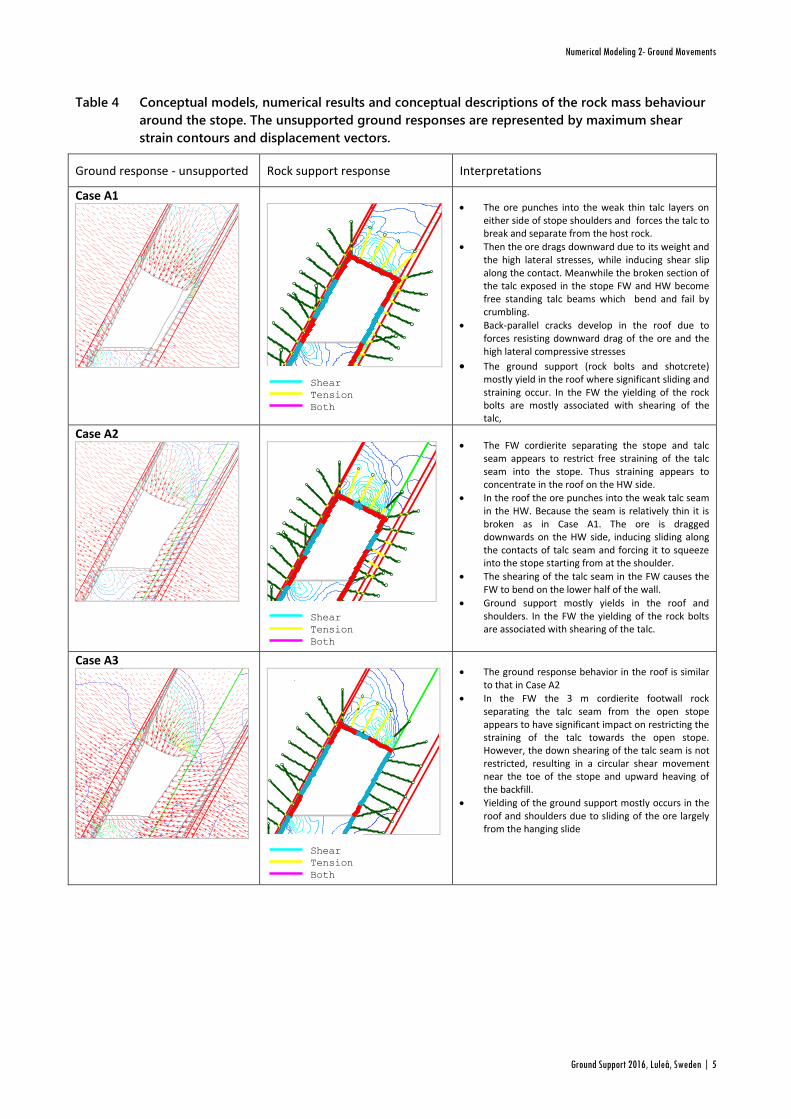
Table 4 Conceptual models, numerical results and conceptual descriptions of the rock mass behaviour
around the stope. The unsupported ground responses are represented by maximum shear
strain contours and displacement vectors.
Ground response - unsupported Rock support response Interpretations
Case A1 Maximum
Shear Strain
7.50e-004
2.25e-003
3.75e-003
5.25e-003
6.75e-003
8.25e-003
9.75e-003
1.13e-002
1.28e-002
1.43e-002
1.58e-002
1.73e-002
-11
84
-11
86
-11
88
-11
90
-11
92
-11
94
-11
96
88 90 92 94 96 98 100 102 104 106 108 110 112 114 116 118 120
Shear
Tension
Both
Maximum
Shear Strain
9.50e-004
2.85e-003
4.75e-003
6.65e-003
8.55e-003
1.04e-002
1.24e-002
1.43e-002
1.62e-002
1.81e-002
2.00e-002
2.19e-002
-11
75
-11
80
-11
85
-11
90
-11
95
-12
00
-12
05
-12
10
-12
15
60 65 70 75 80 85 90 95 100 105 110 115 120 125 130 135 140 145 150 155
Shear
Tension
Both
Maximum
Shear Strain
1.50e-003
4.50e-003
7.50e-003
1.05e-002
1.35e-002
1.65e-002
1.95e-002
2.25e-002
2.55e-002
2.85e-002
3.15e-002
3.45e-002
-11
84
-11
86
-11
88
-11
90
-11
92
-11
94
-11
96
-11
98
-12
00
112 114 116 118 120 122 124 126 128 130 132 134 136 138 140 142 144 146 148 150 152
The ore punches into the weak thin talc layers on either side of stope shoulders and forces the talc to break and separate from the host rock.
Then the ore drags downward due to its weight and the high lateral stresses, while inducing shear slip along the contact. Meanwhile the broken section of the talc exposed in the stope FW and HW become free standing talc beams which bend and fail by crumbling.
Back-parallel cracks develop in the roof due to forces resisting downward drag of the ore and the high lateral compressive stresses
The ground support (rock bolts and shotcrete) mostly yield in the roof where significant sliding and straining occur. In the FW the yielding of the rock bolts are mostly associated with shearing of the talc,
Case A2 Maximum
Shear Strain
7.50e-004
2.25e-003
3.75e-003
5.25e-003
6.75e-003
8.25e-003
9.75e-003
1.13e-002
1.28e-002
1.43e-002
1.58e-002
1.73e-002
-11
84
-11
86
-11
88
-11
90
-11
92
-11
94
-11
96
88 90 92 94 96 98 100 102 104 106 108 110 112 114 116 118
Shear
Tension
Both
Maximum
Shear Strain
7.50e-004
2.25e-003
3.75e-003
5.25e-003
6.75e-003
8.25e-003
9.75e-003
1.13e-002
1.28e-002
1.43e-002
1.58e-002
1.73e-002
-11
80
-11
85
-11
90
-11
95
-12
00
-12
05
-12
10
-12
15
55 60 65 70 75 80 85 90 95 100 105 110 115 120 125 130 135 140 145
Shear
Tension
Both
Maximum
Shear Strain
1.50e-003
4.50e-003
7.50e-003
1.05e-002
1.35e-002
1.65e-002
1.95e-002
2.25e-002
2.55e-002
2.85e-002
3.15e-002
3.45e-002
-11
84
-11
86
-11
88
-11
90
-11
92
-11
94
-11
96
-11
98
-12
00
112 114 116 118 120 122 124 126 128 130 132 134 136 138 140 142 144 146 148 150 152
The FW cordierite separating the stope and talc seam appears to restrict free straining of the talc seam into the stope. Thus straining appears to concentrate in the roof on the HW side.
In the roof the ore punches into the weak talc seam in the HW. Because the seam is relatively thin it is broken as in Case A1. The ore is dragged downwards on the HW side, inducing sliding along the contacts of talc seam and forcing it to squeeze into the stope starting from at the shoulder.
The shearing of the talc seam in the FW causes the FW to bend on the lower half of the wall.
Ground support mostly yields in the roof and shoulders. In the FW the yielding of the rock bolts are associated with shearing of the talc.
Case A3
Maximum
Shear Strain
5.50e-004
1.65e-003
2.75e-003
3.85e-003
4.95e-003
6.05e-003
7.15e-003
8.25e-003
9.35e-003
1.04e-002
1.16e-002
1.27e-002
-11
80
-11
82
-11
84
-11
86
-11
88
-11
90
-11
92
-11
94
-11
96
82 84 86 88 90 92 94 96 98 100 102 104 106 108 110 112 114 116 118 120 122
Shear
Tension
Both
Maximum
Shear Strain
9.00e-004
2.70e-003
4.50e-003
6.30e-003
8.10e-003
9.90e-003
1.17e-002
1.35e-002
1.53e-002
1.71e-002
1.89e-002
2.07e-002
-11
80
-11
85
-11
90
-11
95
-12
00
-12
05
-12
10
-12
15
60 65 70 75 80 85 90 95 100 105 110 115 120 125 130 135 140
Shear
Tension
Both
Maximum
Shear Strain
1.50e-003
4.50e-003
7.50e-003
1.05e-002
1.35e-002
1.65e-002
1.95e-002
2.25e-002
2.55e-002
2.85e-002
3.15e-002
3.45e-002
-11
84
-11
86
-11
88
-11
90
-11
92
-11
94
-11
96
-11
98
-12
00
112 114 116 118 120 122 124 126 128 130 132 134 136 138 140 142 144 146 148 150 152
The ground response behavior in the roof is similar to that in Case A2
In the FW the 3 m cordierite footwall rock separating the talc seam from the open stope appears to have significant impact on restricting the straining of the talc towards the open stope. However, the down shearing of the talc seam is not restricted, resulting in a circular shear movement near the toe of the stope and upward heaving of the backfill.
Yielding of the ground support mostly occurs in the roof and shoulders due to sliding of the ore largely from the hanging slide

Ground support modelling involving large ground deformation: Simulation of conceptual cases – Part 2 D.Saiang and E.Nordlund
6 |Ground Support 2016, Luleå, Sweden
Case B1
Maximum
Shear Strain
1.00e-003
3.00e-003
5.00e-003
7.00e-003
9.00e-003
1.10e-002
1.30e-002
1.50e-002
1.70e-002
1.90e-002
2.10e-002
2.30e-002
-11
78
-11
80
-11
82
-11
84
-11
86
-11
88
-11
90
-11
92
-11
94
-11
96
84 86 88 90 92 94 96 98 100 102 104 106 108 110 112 114 116 118 120 122 124 126
Shear
Tension
Both
Maximum
Shear Strain
2.00e-003
6.00e-003
1.00e-002
1.40e-002
1.80e-002
2.20e-002
2.60e-002
3.00e-002
3.40e-002
3.80e-002
4.20e-002
4.60e-002
-11
85
-11
90
-11
95
-12
00
-12
05
-12
10
70 75 80 85 90 95 100 105 110 115 120 125 130
Shear
Tension
Both
Maximum
Shear Strain
1.50e-003
4.50e-003
7.50e-003
1.05e-002
1.35e-002
1.65e-002
1.95e-002
2.25e-002
2.55e-002
2.85e-002
3.15e-002
3.45e-002
-11
84
-11
86
-11
88
-11
90
-11
92
-11
94
-11
96
-11
98
-12
00
112 114 116 118 120 122 124 126 128 130 132 134 136 138 140 142 144 146 148 150 152
The behaviour is similar to that in Case A1. However, the deformation in the footwall is greater than in Case A1 due to thicker talc seam.
Notably the ore in the roof of the ore punches into the weak talc seam in the FW, forcing it to bulge immediately under the FW shoulder. Because the seam is relatively thick it is not broken. The ore is dragged downwards on both sides, inducing sliding along the contacts of the talc seam and forcing it to squeeze into the stope.
The downward drag of the ore is notable on the FW side.
The ground support yields in the roof because of the downward drag of the ore.
In the FW the ground support is yielding due to shearing of the talc and the bulging of talc as ore compresses the talc after punching through the FW near the shoulder
Case B2 Maximum
Shear Strain
8.00e-004
2.40e-003
4.00e-003
5.60e-003
7.20e-003
8.80e-003
1.04e-002
1.20e-002
1.36e-002
1.52e-002
1.68e-002
1.84e-002
-11
82
-11
84
-11
86
-11
88
-11
90
-11
92
-11
94
88 90 92 94 96 98 100 102 104 106 108 110 112 114 116 118
Shear
Tension
Both
Maximum
Shear Strain
1.00e-003
3.00e-003
5.00e-003
7.00e-003
9.00e-003
1.10e-002
1.30e-002
1.50e-002
1.70e-002
1.90e-002
2.10e-002
2.30e-002
-11
85
-11
90
-11
95
-12
00
-12
05
-12
10
70 75 80 85 90 95 100 105 110 115 120 125 130 135
Shear
Tension
Both
Maximum
Shear Strain
1.50e-003
4.50e-003
7.50e-003
1.05e-002
1.35e-002
1.65e-002
1.95e-002
2.25e-002
2.55e-002
2.85e-002
3.15e-002
3.45e-002
-11
84
-11
86
-11
88
-11
90
-11
92
-11
94
-11
96
-11
98
-12
00
112 114 116 118 120 122 124 126 128 130 132 134 136 138 140 142 144 146 148 150 152
Similar behavior as in Case A2. Slightly greater movement in the footwall than in Case A2 due to thicker talc seam.
The cordierite FW rock separating the talc seam from the open stope obviously restricts free straining of the talc towards the open stope.
Hence, the downward drag of the ore mostly occurs towards the HW side where sliding occurs mostly along the thin talc band on the HW.
The ground support yields in the roof and in the shoulder of the HW, which corresponds to the movement described above
In the FW the rock bolts yield in tension inside the talc zone due to bending that is resulting from the downward shearing of the talc
The circular shearing at the toe of the stope causes the FW to bulge near the toe of the stope, causing the shotcrete to yield.
Case B3
Maximum
Shear Strain
6.00e-004
1.80e-003
3.00e-003
4.20e-003
5.40e-003
6.60e-003
7.80e-003
9.00e-003
1.02e-002
1.14e-002
1.26e-002
1.38e-002
-11
75
-11
77
.5-1
18
0-1
18
2.5
-11
85
-11
87
.5-1
19
0-1
19
2.5
-11
95
-11
97
.5
80 82.5 85 87.5 90 92.5 95 97.5 100 102.5 105 107.5 110 112.5 115 117.5 120 122.5 125 127.5 130 132.5
Shear
Tension
Both
Maximum
Shear Strain
7.50e-004
2.25e-003
3.75e-003
5.25e-003
6.75e-003
8.25e-003
9.75e-003
1.13e-002
1.28e-002
1.43e-002
1.58e-002
1.73e-002
-11
85
-11
90
-11
95
-12
00
-12
05
-12
10
70 75 80 85 90 95 100 105 110 115 120 125 130
Shear
Tension
Both
Maximum
Shear Strain
1.50e-003
4.50e-003
7.50e-003
1.05e-002
1.35e-002
1.65e-002
1.95e-002
2.25e-002
2.55e-002
2.85e-002
3.15e-002
3.45e-002
-11
84
-11
86
-11
88
-11
90
-11
92
-11
94
-11
96
-11
98
-12
00
112 114 116 118 120 122 124 126 128 130 132 134 136 138 140 142 144 146 148 150 152
Similar behavior as in Case A3 and B2
The farther the talc seam is to the open stope the less it deforms directly into the stope. However, the downward shearing of the talc forms a circular failure surface at the toe of the stope. Floor heaving of the backfill is obvious.
Yielding of the ground support is largely occurring in the roof due to downward sliding of ore.
The farther talc seam is from the stope the less the impact it has on the ground support.

Numerical Modeling 2- Ground Movements
Ground Support 2016, Luleå, Sweden | 7
Case C1 Maximum
Shear Strain
1.50e-003
4.50e-003
7.50e-003
1.05e-002
1.35e-002
1.65e-002
1.95e-002
2.25e-002
2.55e-002
2.85e-002
3.15e-002
3.45e-002
-11
84
-11
86
-11
88
-11
90
-11
92
-11
94
-11
96
88 90 92 94 96 98 100 102 104 106 108 110 112 114 116
Shear
Tension
Both
Maximum
Shear Strain
3.00e-003
9.00e-003
1.50e-002
2.10e-002
2.70e-002
3.30e-002
3.90e-002
4.50e-002
5.10e-002
5.70e-002
6.30e-002
6.90e-002
-11
80
-11
85
-11
90
-11
95
-12
00
-12
05
-12
10
65 70 75 80 85 90 95 100 105 110 115 120 125 130 135 140
Shear
Tension
Both
Maximum
Shear Strain
1.50e-003
4.50e-003
7.50e-003
1.05e-002
1.35e-002
1.65e-002
1.95e-002
2.25e-002
2.55e-002
2.85e-002
3.15e-002
3.45e-002
-11
84
-11
86
-11
88
-11
90
-11
92
-11
94
-11
96
-11
98
-12
00
112 114 116 118 120 122 124 126 128 130 132 134 136 138 140 142 144 146 148 150 152
The behaviour is similar to that in Cases A1 and B1 except the deformation is quite large in the footwall because of the much larger talc seam.
The ground support yields significantly in the roof and FW.
Case C2
Maximum
Shear Strain
1.50e-003
4.50e-003
7.50e-003
1.05e-002
1.35e-002
1.65e-002
1.95e-002
2.25e-002
2.55e-002
2.85e-002
3.15e-002
3.45e-002
-11
80
-11
82
-11
84
-11
86
-11
88
-11
90
-11
92
-11
94
-11
96
86 88 90 92 94 96 98 100 102 104 106 108 110 112 114 116 118 120 122 124
Shear
Tension
Both
Maximum
Shear Strain
1.00e-003
3.00e-003
5.00e-003
7.00e-003
9.00e-003
1.10e-002
1.30e-002
1.50e-002
1.70e-002
1.90e-002
2.10e-002
2.30e-002
-11
80
-11
85
-11
90
-11
95
-12
00
-12
05
-12
10
65 70 75 80 85 90 95 100 105 110 115 120 125 130 135 140
Shear
Tension
Both
Maximum
Shear Strain
1.50e-003
4.50e-003
7.50e-003
1.05e-002
1.35e-002
1.65e-002
1.95e-002
2.25e-002
2.55e-002
2.85e-002
3.15e-002
3.45e-002
-11
84
-11
86
-11
88
-11
90
-11
92
-11
94
-11
96
-11
98
-12
00
112 114 116 118 120 122 124 126 128 130 132 134 136 138 140 142 144 146 148 150 152
The behaviour is similar to that in Cases A2 and B2 except the deformation is larger in the footwall because of the thicker talc seam size.
The 1 m thick cordierite FW rock notably prevents the ore from punching into the talc as in Case C1. So there is no swelling of the talc directly under the FW shoulder.
However, significant downward shearing of the talc leads to bulging near the toe of the FW
The rock support yields notably in the roof of the HW side where the ore is free to slide but not on the FW side
The downward shearing of the talc causes the ground support to yield mostly on the lower half of the FW.
Case C3 Maximum
Shear Strain
1.50e-003
4.50e-003
7.50e-003
1.05e-002
1.35e-002
1.65e-002
1.95e-002
2.25e-002
2.55e-002
2.85e-002
3.15e-002
3.45e-002
-11
82
-11
84
-11
86
-11
88
-11
90
-11
92
-11
94
-11
96
-11
98
84 86 88 90 92 94 96 98 100 102 104 106 108 110 112 114 116 118 120 122 124 126
Shear
Tension
Both
Maximum
Shear Strain
1.50e-003
4.50e-003
7.50e-003
1.05e-002
1.35e-002
1.65e-002
1.95e-002
2.25e-002
2.55e-002
2.85e-002
3.15e-002
3.45e-002
-11
85
-11
90
-11
95
-12
00
-12
05
-12
10
65 70 75 80 85 90 95 100 105 110 115 120 125 130 135
Shear
Tension
Both
Maximum
Shear Strain
1.50e-003
4.50e-003
7.50e-003
1.05e-002
1.35e-002
1.65e-002
1.95e-002
2.25e-002
2.55e-002
2.85e-002
3.15e-002
3.45e-002
-11
84
-11
86
-11
88
-11
90
-11
92
-11
94
-11
96
-11
98
-12
00
112 114 116 118 120 122 124 126 128 130 132 134 136 138 140 142 144 146 148 150 152
The behaviour is similar to that in Cases A3 and A3 except the deformation is larger because of the much thicker talc seam.
However, the movements towards the open stope are significantly restricted by the thicker zone of competent cordierite FW rock.
Downward shearing of the talc expresses itself at the toe of the FW resulting in heaving at the FW toe and backfilled floor.
The ground support mostly yield in tension in the roof on the HW side where the ore is free to slide and rotate (as it is restricted on the FW side).

Ground support modelling involving large ground deformation: Simulation of conceptual cases – Part 2 D.Saiang and E.Nordlund
8 |Ground Support 2016, Luleå, Sweden
Case D1
Maximum
Shear Strain
1.50e-003
4.50e-003
7.50e-003
1.05e-002
1.35e-002
1.65e-002
1.95e-002
2.25e-002
2.55e-002
2.85e-002
3.15e-002
3.45e-002
-11
78
-11
80
-11
82
-11
84
-11
86
-11
88
-11
90
-11
92
-11
94
-11
96
86 88 90 92 94 96 98 100 102 104 106 108 110 112 114 116 118 120 122 124 126 128
Shear
Tension
Both
Maximum
Shear Strain
2.00e-003
6.00e-003
1.00e-002
1.40e-002
1.80e-002
2.20e-002
2.60e-002
3.00e-002
3.40e-002
3.80e-002
4.20e-002
4.60e-002
-11
85
-11
87
.5-1
19
0-1
19
2.5
-11
95
-11
97
.5-1
20
0-1
20
2.5
-12
05
-12
07
.5-1
21
0
65 67.5 70 72.5 75 77.5 80 82.5 85 87.5 90 92.5 95 97.5 100 102.5 105 107.5 110 112.5 115 117.5 120 122.5 125 127.5
Shear
Tension
Both
Maximum
Shear Strain
1.50e-003
4.50e-003
7.50e-003
1.05e-002
1.35e-002
1.65e-002
1.95e-002
2.25e-002
2.55e-002
2.85e-002
3.15e-002
3.45e-002
-11
84
-11
86
-11
88
-11
90
-11
92
-11
94
-11
96
-11
98
-12
00
112 114 116 118 120 122 124 126 128 130 132 134 136 138 140 142 144 146 148 150 152
The talc in the roof causes the ore to dislocate, separate and slide on the FW side and in the process it attempts to drag the ore on the HW side with it
Case D2 Maximum
Shear Strain
9.50e-004
2.85e-003
4.75e-003
6.65e-003
8.55e-003
1.04e-002
1.24e-002
1.43e-002
1.62e-002
1.81e-002
2.00e-002
2.19e-002
-11
80
-11
82
-11
84
-11
86
-11
88
-11
90
-11
92
-11
94
-11
96
88 90 92 94 96 98 100 102 104 106 108 110 112 114 116 118 120 122 124
Shear
Tension
Both
Maximum
Shear Strain
9.50e-004
2.85e-003
4.75e-003
6.65e-003
8.55e-003
1.04e-002
1.24e-002
1.43e-002
1.62e-002
1.81e-002
2.00e-002
2.19e-002
-11
85
-11
90
-11
95
-12
00
-12
05
-12
10
70 75 80 85 90 95 100 105 110 115 120 125 130
Shear
Tension
Both
Maximum
Shear Strain
1.50e-003
4.50e-003
7.50e-003
1.05e-002
1.35e-002
1.65e-002
1.95e-002
2.25e-002
2.55e-002
2.85e-002
3.15e-002
3.45e-002
-11
84
-11
86
-11
88
-11
90
-11
92
-11
94
-11
96
-11
98
-12
00
112 114 116 118 120 122 124 126 128 130 132 134 136 138 140 142 144 146 148 150 152
The ground behaviour is similar to that in Case D1, however the competent FW cordierite in the FW prevents the ore from punching into the FW talc.
But, the downward shearing of the talc continues and attempts to express itself at the toe of the stope with a circular shear characteristics
The ground support yields in the roof and in the footwall inside the talc.
However, on the lower half of the stope the rock bolts experience more yielding than in the upper half of the stope.
Case D3 Maximum
Shear Strain
6.00e-004
1.80e-003
3.00e-003
4.20e-003
5.40e-003
6.60e-003
7.80e-003
9.00e-003
1.02e-002
1.14e-002
1.26e-002
1.38e-002
-11
80
-11
82
-11
84
-11
86
-11
88
-11
90
-11
92
-11
94
-11
96
84 86 88 90 92 94 96 98 100 102 104 106 108 110 112 114 116 118 120 122 124 126
Shear
Tension
Both
Maximum
Shear Strain
6.00e-004
1.80e-003
3.00e-003
4.20e-003
5.40e-003
6.60e-003
7.80e-003
9.00e-003
1.02e-002
1.14e-002
1.26e-002
1.38e-002
-11
80
-11
85
-11
90
-11
95
-12
00
-12
05
-12
10
-12
15
60 65 70 75 80 85 90 95 100 105 110 115 120 125 130 135
Shear
Tension
Both
Maximum
Shear Strain
1.50e-003
4.50e-003
7.50e-003
1.05e-002
1.35e-002
1.65e-002
1.95e-002
2.25e-002
2.55e-002
2.85e-002
3.15e-002
3.45e-002
-11
84
-11
86
-11
88
-11
90
-11
92
-11
94
-11
96
-11
98
-12
00
112 114 116 118 120 122 124 126 128 130 132 134 136 138 140 142 144 146 148 150 152
The ground behavior is similar to that in Case D2, however the competent FW cordierite in the FW prevents the ore from punching into the FW talc.
The 3 m thick FW cordierite significantly restricts the deformation of talc.
But, the downward shearing of the talc continues in the FW.
The ground support yields in the roof and in the footwall inside the talc.
However, on the lower half of the stope the rock bolts experience more yielding than in the upper half of the stope. This is because the shearing is more pronounced near the toe.

Numerical Modeling 2- Ground Movements
Ground Support 2016, Luleå, Sweden | 9
Case E1 Maximum
Shear Strain
1.00e-003
3.00e-003
5.00e-003
7.00e-003
9.00e-003
1.10e-002
1.30e-002
1.50e-002
1.70e-002
1.90e-002
2.10e-002
2.30e-002
-11
84
-11
86
-11
88
-11
90
-11
92
-11
94
90 92 94 96 98 100 102 104 106 108 110 112 114 116 118
Shear
Tension
Both
Maximum
Shear Strain
2.00e-003
6.00e-003
1.00e-002
1.40e-002
1.80e-002
2.20e-002
2.60e-002
3.00e-002
3.40e-002
3.80e-002
4.20e-002
4.60e-002
-11
85
-11
90
-11
95
-12
00
-12
05
-12
10
-12
15
65 70 75 80 85 90 95 100 105 110 115 120 125 130 135
Shear
Tension
Both
Maximum
Shear Strain
1.50e-003
4.50e-003
7.50e-003
1.05e-002
1.35e-002
1.65e-002
1.95e-002
2.25e-002
2.55e-002
2.85e-002
3.15e-002
3.45e-002
-11
84
-11
86
-11
88
-11
90
-11
92
-11
94
-11
96
-11
98
-12
00
112 114 116 118 120 122 124 126 128 130 132 134 136 138 140 142 144 146 148 150 152
The behavior is similar to that in Case B1, except that the pyrite seam appears to significantly resist free shearing of the talc into the open stope.
Nevertheless, the ore still punches into the talc seams (both in FW and HW) and compresses the talc seams as it drags downwards.
The ground support yields in the roof due to downward movement of the ore.
In the FW the ground supports yield due to shearing of the FW talc.
Case E2 Maximum
Shear Strain
1.00e-003
3.00e-003
5.00e-003
7.00e-003
9.00e-003
1.10e-002
1.30e-002
1.50e-002
1.70e-002
1.90e-002
2.10e-002
2.30e-002
-11
80
-11
82
-11
84
-11
86
-11
88
-11
90
-11
92
-11
94
-11
96
84 86 88 90 92 94 96 98 100 102 104 106 108 110 112 114 116 118 120 122
Shear
Tension
Both
Maximum
Shear Strain
2.00e-003
6.00e-003
1.00e-002
1.40e-002
1.80e-002
2.20e-002
2.60e-002
3.00e-002
3.40e-002
3.80e-002
4.20e-002
4.60e-002
-11
80
-11
85
-11
90
-11
95
-12
00
-12
05
-12
10
65 70 75 80 85 90 95 100 105 110 115 120 125 130 135
Shear
Tension
Both
Maximum
Shear Strain
1.50e-003
4.50e-003
7.50e-003
1.05e-002
1.35e-002
1.65e-002
1.95e-002
2.25e-002
2.55e-002
2.85e-002
3.15e-002
3.45e-002
-11
84
-11
86
-11
88
-11
90
-11
92
-11
94
-11
96
-11
98
-12
00
112 114 116 118 120 122 124 126 128 130 132 134 136 138 140 142 144 146 148 150 152
The behavior is very much similar to that in Case E1.
For the pyrite to be effective in arresting free deformation of the talc in the stope it must be present on the inner side While the talc is outside relative stope wall.
The ground support yields in the roof close to the FW shoulders. On the lower half of the FW the rock bolts yield due shearing of the talc.
Case E3 Maximum
Shear Strain
2.00e-003
6.00e-003
1.00e-002
1.40e-002
1.80e-002
2.20e-002
2.60e-002
3.00e-002
3.40e-002
3.80e-002
4.20e-002
4.60e-002
-11
84
-11
86
-11
88
-11
90
-11
92
-11
94
-11
96
90 92 94 96 98 100 102 104 106 108 110 112 114 116 118
Shear
Tension
Both
Maximum
Shear Strain
2.00e-003
6.00e-003
1.00e-002
1.40e-002
1.80e-002
2.20e-002
2.60e-002
3.00e-002
3.40e-002
3.80e-002
4.20e-002
4.60e-002
-11
85
-11
90
-11
95
-12
00
-12
05
-12
10
70 75 80 85 90 95 100 105 110 115 120 125 130
Shear
Tension
Both
Maximum
Shear Strain
1.50e-003
4.50e-003
7.50e-003
1.05e-002
1.35e-002
1.65e-002
1.95e-002
2.25e-002
2.55e-002
2.85e-002
3.15e-002
3.45e-002
-11
84
-11
86
-11
88
-11
90
-11
92
-11
94
-11
96
-11
98
-12
00
112 114 116 118 120 122 124 126 128 130 132 134 136 138 140 142 144 146 148 150 152
The behavior is very much similar to that in Case E2. The talc seam is relatively thick compared to the thin pyrite seam. Hence the behavior is also similar to that in Case C1.
The ground support yields in the roof and the FW shoulder. On the lower half of the FW the rock bolts yield due shearing of the talc.
Ground support modelling involving large ground deformation: Simulation of conceptual cases – Part 2 D.Saiang and E.Nordlund
10 |Ground Support 2016, Luleå, Sweden
Case F1 Maximum
Shear Strain
2.00e-003
6.00e-003
1.00e-002
1.40e-002
1.80e-002
2.20e-002
2.60e-002
3.00e-002
3.40e-002
3.80e-002
4.20e-002
4.60e-002
-11
84
-11
86
-11
88
-11
90
-11
92
-11
94
90 92 94 96 98 100 102 104 106 108 110 112 114 116 118 120
Shear
Tension
Both
Maximum
Shear Strain
2.00e-003
6.00e-003
1.00e-002
1.40e-002
1.80e-002
2.20e-002
2.60e-002
3.00e-002
3.40e-002
3.80e-002
4.20e-002
4.60e-002
-11
85
-11
90
-11
95
-12
00
-12
05
-12
10
65 70 75 80 85 90 95 100 105 110 115 120 125 130
Shear
Tension
Both
Maximum
Shear Strain
1.50e-003
4.50e-003
7.50e-003
1.05e-002
1.35e-002
1.65e-002
1.95e-002
2.25e-002
2.55e-002
2.85e-002
3.15e-002
3.45e-002
-11
84
-11
86
-11
88
-11
90
-11
92
-11
94
-11
96
-11
98
-12
00
112 114 116 118 120 122 124 126 128 130 132 134 136 138 140 142 144 146 148 150 152
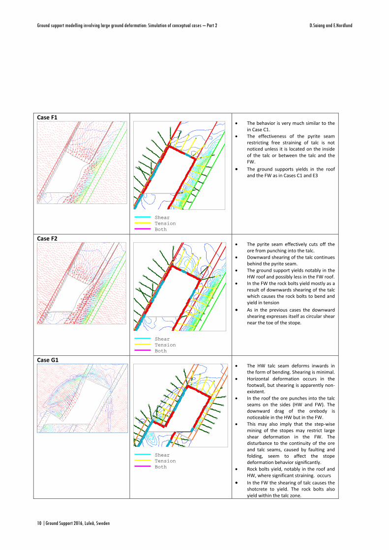
The behavior is very much similar to the in Case C1.
The effectiveness of the pyrite seam restricting free straining of talc is not noticed unless it is located on the inside of the talc or between the talc and the FW.
The ground supports yields in the roof and the FW as in Cases C1 and E3
Case F2 Maximum
Shear Strain
1.50e-003
4.50e-003
7.50e-003
1.05e-002
1.35e-002
1.65e-002
1.95e-002
2.25e-002
2.55e-002
2.85e-002
3.15e-002
3.45e-002
-11
82
-11
84
-11
86
-11
88
-11
90
-11
92
-11
94
-11
96
86 88 90 92 94 96 98 100 102 104 106 108 110 112 114 116 118 120 122
Shear
Tension
Both
Maximum
Shear Strain
1.50e-003
4.50e-003
7.50e-003
1.05e-002
1.35e-002
1.65e-002
1.95e-002
2.25e-002
2.55e-002
2.85e-002
3.15e-002
3.45e-002
-11
85
-11
90
-11
95
-12
00
-12
05
-12
10
70 75 80 85 90 95 100 105 110 115 120 125 130
Shear
Tension
Both
Maximum
Shear Strain
1.50e-003
4.50e-003
7.50e-003
1.05e-002
1.35e-002
1.65e-002
1.95e-002
2.25e-002
2.55e-002
2.85e-002
3.15e-002
3.45e-002
-11
84
-11
86
-11
88
-11
90
-11
92
-11
94
-11
96
-11
98
-12
00
112 114 116 118 120 122 124 126 128 130 132 134 136 138 140 142 144 146 148 150 152
The pyrite seam effectively cuts off the ore from punching into the talc.
Downward shearing of the talc continues behind the pyrite seam.
The ground support yields notably in the HW roof and possibly less in the FW roof.
In the FW the rock bolts yield mostly as a result of downwards shearing of the talc which causes the rock bolts to bend and yield in tension
As in the previous cases the downward shearing expresses itself as circular shear near the toe of the stope.
Case G1 Maximum
Shear Strain
6.00e-004
1.80e-003
3.00e-003
4.20e-003
5.40e-003
6.60e-003
7.80e-003
9.00e-003
1.02e-002
1.14e-002
1.26e-002
1.38e-002
-11
84
-11
86
-11
88
-11
90
-11
92
-11
94
92 94 96 98 100 102 104 106 108 110 112 114 116 118
Shear
Tension
Both
Maximum
Shear Strain
1.50e-003
4.50e-003
7.50e-003
1.05e-002
1.35e-002
1.65e-002
1.95e-002
2.25e-002
2.55e-002
2.85e-002
3.15e-002
3.45e-002
-11
75
-11
80
-11
85
-11
90
-11
95
-12
00
-12
05
-12
10
65 70 75 80 85 90 95 100 105 110 115 120 125 130 135 140 145
Shear
Tension
Both
Maximum
Shear Strain
1.50e-003
4.50e-003
7.50e-003
1.05e-002
1.35e-002
1.65e-002
1.95e-002
2.25e-002
2.55e-002
2.85e-002
3.15e-002
3.45e-002
-11
84
-11
86
-11
88
-11
90
-11
92
-11
94
-11
96
-11
98
-12
00
112 114 116 118 120 122 124 126 128 130 132 134 136 138 140 142 144 146 148 150 152
The HW talc seam deforms inwards in the form of bending. Shearing is minimal.
Horizontal deformation occurs in the footwall, but shearing is apparently non-existent.
In the roof the ore punches into the talc seams on the sides (HW and FW). The downward drag of the orebody is noticeable in the HW but in the FW.
This may also imply that the step-wise mining of the stopes may restrict large shear deformation in the FW. The disturbance to the continuity of the ore and talc seams, caused by faulting and folding, seem to affect the stope deformation behavior significantly.
Rock bolts yield, notably in the roof and HW, where significant straining. occurs
In the FW the shearing of talc causes the shotcrete to yield. The rock bolts also yield within the talc zone.

Numerical Modeling 2- Ground Movements
Ground Support 2016, Luleå, Sweden | 11
Case G2 Maximum
Shear Strain
1.50e-003
4.50e-003
7.50e-003
1.05e-002
1.35e-002
1.65e-002
1.95e-002
2.25e-002
2.55e-002
2.85e-002
3.15e-002
3.45e-002
-11
86
-11
88
-11
90
-11
92
-11
94
-11
96
98 100 102 104 106 108 110 112 114 116 118 120 122
Shear
Tension
Both
Maximum
Shear Strain
2.50e-003
7.50e-003
1.25e-002
1.75e-002
2.25e-002
2.75e-002
3.25e-002
3.75e-002
4.25e-002
4.75e-002
5.25e-002
5.75e-002
-11
75
-11
80
-11
85
-11
90
-11
95
-12
00
-12
05
-12
10
70 75 80 85 90 95 100 105 110 115 120 125 130 135 140 145 150 155
Shear
Tension
Both
Maximum
Shear Strain
1.50e-003
4.50e-003
7.50e-003
1.05e-002
1.35e-002
1.65e-002
1.95e-002
2.25e-002
2.55e-002
2.85e-002
3.15e-002
3.45e-002
-11
84
-11
86
-11
88
-11
90
-11
92
-11
94
-11
96
-11
98
-12
00
112 114 116 118 120 122 124 126 128 130 132 134 136 138 140 142 144 146 148 150 152
The HW talc seam deforms by bending into the stope, with limited amount of shearing.
The FW talc seam also deforms inwards and perpendicular to the stope walls. Shearing is limited to the FW shoulder.
In the roof the ore punches into the FW and HW talc seams. Downward drag of the ore causes shearing that is limited to the shoulders of the stope walls.
The step-wise stoping significantly minimizes the deformation of HW and FW.
The ground support yields primarily due to the deformation of talc in the HW and FW.
In the roof the ground support yielding results from downward movement of the ore.
5 Discussions
The effects of talc on the deformation of the stope are affected by several factors:
Thickness of the talc seams: Thin bands of talc generally respond by bending, after being separated along the contact. Talc seams that immediately surround the ore are easily broken in the roof as the competent ore punches into the soft talc. Once broken the weight of the ore is applied directly on to the standing talc band causing it to flex and fail by crumbling. Thicker seams of talc, which are typically found in the footwall, generally squeeze and dilate into the stope. This is caused by a combination of the high lateral stresses and the downward compression caused by the weight of the ore. “Bellying” of the FW also seems to be associated the thick talc seams. Wedges of cracks will appear in the middle of the FW height as a result. At the base of the FW and under the backfill, wedge shaped circular failure may occur. The backfill will heave if the shear failure occurs under the backfill.
Location of the talc seams.: The farther the talc seams are from the stope, the effect diminishes. The competent rock mass separating the stope and talc seam behaves like a rock pillar. The nearer the talc is to the stope, the competent rock mass in between behaves like a slender pillar. If the talc seam is thick, the impact on the slender rock pillar is significant, as it is forced to bend into the stope.
Occurrence of pyrite seams with talc: Pyrite seams appear to resist shearing of the talc, due to its high frictional resistance. This observation is consistent with the field observations made in Cut # 4 where lenses of pyrite were seen in the camera boreholes in some of the sections
Undercutting of talc seams: The mechanisms that drive deformation and failure are also affected by whether the seams are undercut or not. If the seams are not undercut by the stope then bending is the primary mechanism. If the seams are undercut then shearing is the primary mechanism.
Talc through middle of the ore: If the talc seam is in the middle of the ore and is undercut, it is forced to extrude by the high lateral stresses.
Other phenomena have also been observed:
Development of back parallel cracks in the roof: The parallel to sub parallel cracks appear when the ore is dragged downwards, under its weight, with the talc contact acting as the sliding surface. The downward drag of the ore can be visualized as acting on “fix-free” boundary. The movement is fixed on the boundary where the talc is absent; while it is free to move downward along the boundary where the talc is present. Therefore movement is first initiated from the wall where the

Ground support modelling involving large ground deformation: Simulation of conceptual cases – Part 2 D.Saiang and E.Nordlund
12 |Ground Support 2016, Luleå, Sweden
talc is present and because it is fixed on other wall a rotational moment is created, leading to church dome shaped back parallel cracks. A rock bolt would be subjected to shear, bending and rotational moment under this scenario. If talc is present on both sides (HW and FW), the ore tends to slide into the stope under gravity, as well as being forced by the high lateral stresses. Back parallel cracks develop and propagate into the back until a state of equilibrium is reached. A rock bolt would be in tension under this condition.
Effect of faulting, folding and shearing: Faulting, folding and shearing results in irregular orebody geometry. This results in cuts that offset each other, both up dip and along the strike. The offsetting tends to cause less ground deformation for the subsequent cuts. This scenario was clearly observed in the experimental stope, where cuts are offset and is likely to be one of the main reasons for the low deformation magnitudes observed in Cut #4. From the ground control point of view the offsetting of cuts could be an advantage.
Since the maximum principal stress is known to be perpendicular to the orebody then bending will be main the deformation mode if shearing does not occur. This is clearly seen in the conceptual models where the displacement vectors are perpendicular to stope walls where the talc is either absent or thin. Although the conceptual models show instabilities in FW, HW and the roof, the instabilities in the roof are significant with respect to rock fall and immediate safety. Obviously the stability of the walls is important for stabilizing the roof, since instability in the walls would provide a pathway for the entire instability leading up to the roof. Most of the fallouts would have occurred at the same time as the blasting. This is evident from the profiles in the test area where fallouts have occurred during blasting near the HW and FW shoulders and other areas talc has been undercut.
6 Conclusion
The conceptual cases which realistically represent the observations at Kristineberg mine show many facets of the ground deformation characteristics; bending, shearing, dilation and bulging, and direction tension and compression. These mechanisms occur either simultaneously or sequentially depending on the advancement of the cut, characteristics of the wall rocks and the stope geometry. Consequently the ground support elements are subjected to all these mechanisms either simultaneously or sequentially too. The spatial characteristics of the highly altered talc-schist has a major influence in the stope deformation characteristics, while the presence of pyrite is noted to reduce to deformation to some extent by resisting the shearing of the altered talc-schist.
Acknowledgement
The authors wish to acknowledge LTU, LKAB and Boliden Mineral AB colleagues involved in the ground support research and financing provided by Boliden Mineral AB, LKAB, VINNOVA and Centre of Applied Mining and Metallurgy (CAMM) at Luleå University of Technology, .
References
Krauland, N, Marklund, P, Board, M, 2001, ‘Rock support in cut-and-fill mining at the Kristineberg mine’, in W A Hustrulid & R L Bullock (eds), Underground Mining Methods, Society of Mining, Metallurgy and Exploration Inc.
Board, M, Rosengren, L, 1992, ‘Simulation of sill pillar in mining at 600 m depth at Kristineberg mine’ Project 2000, Technical Report prepared for Boliden Mineral AB.
Board, M, Israelsson, J, & Rosengren, L, 1991, Calibration of the detailed model of the 804 reference room (G 2000 91:27 Projekt 323).
Saiang, D, Nordlund, E, 2016, “Ground Support Modelling Involving Ground Deformation: Simulation of Field Observations – Part 1”, In Ground Support 2016, Luleå, Sweden.