ground vibration characterization of a missile system for
TRANSCRIPT

Calhoun: The NPS Institutional Archive
Theses and Dissertations Thesis Collection
1990-06
Ground vibration characterization of a missile
system for flutter energy definition
Hollyer, John Barry
Monterey, California: Naval Postgraduate School
http://hdl.handle.net/10945/27757

NAVAL POSTGRADUATE SCHOOLMonterey, California
AD-A237 026111II 1I1 1 E II 1111111111111111ll!
IDTIC'nx~a A j-- 0 L E CT E 0=5UN 19 19V
THESIS SB.0.
Ground Vibration Characterization of aMissile System for Flutter Energy Definition
by
John Barry Hollyer
June 1990
Thesis Advisor Professor Edward M. Wu
Approved for public release; distribution is unlimited
91-02228llli~~~~l ~II ' El I '~l ,I

UnclassifiedSecurity Classification of this page
REPORT DOCUMENTATION PAGEla Report Security Classification Unclassified lb Restrictive Markings2a Security Classification Authority 3 Distribution Availability of Report
2b Declassification/Downgrading Schedule Approved for public release; distribution is unlimited4 Performing Organization Report Number(s) 5 Monitoring Organization Report Number(s)6a Name of Performing Organization I 6b Office Symbol 7 a Name of Monitoring OrganizationNaval Postgraduate School (If Applicable) 67 Naval Postgraduate School6c Address (city, state, and ZIP code) 7b Address (city, state, and ZIP code)Monterey, CA 93943-5000 Monterey, CA 93943-50008a Name of Funding/Sponsoring Organization 8b Office Symbol 9 Procurement Instrument Identification Number
I(If Applicable)Sc Address (city, state, and ZIP code) 10 Source of Funding Numbers
Prom Element Number IProect No I T No I Work Unit Accessio No
11 Title (Include Security Classification) Ground Vibration Characterization of a Missile System for Flutter EnergyDefinition12 Personal Author(s) John B. Hollyer,LCDR USN13a Type of Report 13b Time Covered 14 Date of Report (year, month,day) 15 Page Count
Master's Thesis From To JJune 1990 7816 Supplementary Notation The views expressed in this thesis are those of the author and do not reflect theofficial policy or position of the Department of Defense or the U.S. Government.17 Cosati Codes 18 Subject Terms (continue on reverse if necessary and identify by block number)
Field Group Subgroup Flutter, P-3, Ground Vibration Tests, Flutter Modeling, continued on reverse
19 Abstract (continue on reverse if necessary and identify by block number
Changing world scenarios and mission requirements have generated the need to retrofit an all aspectdefensive missile system to Patrol airplanes. To this end the AIM-9 Sidewinder was selected and installedon a P-3 at the Naval Air Test Center for envelope expansion and separation tests. The added mass andpitch inertia of this system on the outer wing station may combine with the outer wing characteristics tocause catastrophic flutter. A ground vibration analysis was set up to experimentally measure andanalytically model the modal characteristics of the stand alone weapon assembly. This weapon systemmodal characterization can be analyzed in conjunction with the original bare wing dynamic model leading toan assessment of the flight envelope and a safe in-flight flutter test. The facility and methodologiesestablished in this investigation can also be used to characterize other candidate missile systems. This willprovide timely fleet revelant results and generate expected cost savings of over 200K dollars.
2(0 Distribution/Availability of Abstract 21 Abstract Security Classification
N uiclassified/unlimitcd 1 same as report [I DTIC users Unclassified22a Name of Responsible Individual 22b Telephone (Include Area code) 22c Office Symbol
Edward M. Wu (408) 646-3459 67DD FORM 1473, 81 MAR 83 APR edition may be used until exhausted security classification of this page
All other editions are obsolete U n c I a s s i f i e d

U nclIa ss if ie dSecurity Classification of this page
[18] Modal Modeling
SIN 0102-LF-0J14-6601 security classification of this page
Un clIa s sif ie d

Approved for public release; distribution is unlimited.
Ground Vibration Characterization of a
Missile System for Flutter Energy Definition
by
John Barry HollyerLieutenant Commander, United States Navy
B.S., United States Naval Academy, 1978
Submitted in partial fulfillment of the requirements forthe degree of
MASTER OF SCIENCE IN AERONAUTICALENGINEERING
from the
NAVAL POSTGRADUATE SCHOOLJuT 1990
Auth or:
Approved by: visor
Loui M Z h t, Second Deader
.R. Nd. C hai n.partment of Aeronautics anlAstronautics
iii

ABSTRACT
Changing world scenarios and mission requirements have
generated the need to retrofit an all aspect defensive missile system
to Patrol airplanes. To this end the AIM-9 Sidewinder was selected
and installed on a P-3 at the Naval Air Test Center for envelope
expansion and separation tests. The added mass and pitch inertia of
this system on the outer wing may combine with the outer wing
characteristics to cause catastrophic flutter. A ground vibration
analysis was set up to experimentally measure and analytically
model the modal characteristics of the stand alone weapon assembly.
This weapon system modal characterization can be analyzed in
conjunction with the original bare wing dynamic model leading to an
assessment of the flight envelope and a safe in-flight flutter test. The
facility and methodologies established in this investigation can also
be used to characterize other candidate missile systems. This will
provide timely fleet relevant results and generate expected cost
savings of over 200K dollars.
Accession For
NTIS GRA&I FleDTIC TAB QUntnnounced 0Just I fcatlon,- -
D ist r i-at io / .
- Availability CodeS
Avail and/orDist Special
iv

TABLE OF CONTENTS
1. INTRODUCTION ................................................................... 1
A. BACKGROUND ......................................................... 1
B. PURPOSE ................................................................. 4
C. SCOPE ..................................................................... 5
II. TEST SYSTEM ...................................................................... 6
A . GENERAL .................................................................. 6
B. GVT BASE STRUCTURE ......................................... 6
C. SHAKER ASSEMBLY HARDWARE ......................... 7
D. DATA COLLECTION ................................................ 8
E, M ISSILE SYSTEM ................................................... 9
III. DATA ACQUISITION AND INTERPRETATION .............. 13
A. GENERAL ................................................................. 13
B. PITCH ...................................................................... 18
C. SW AY .......................................................................... 23
D. YAW ......................................................................... 23
IV. M ODELING ....................................................................... 25
A. GENERAL ................................................................. 25
B. THEORY/M ODELING ............................................... 27
C. M ODEL SELECTION ................................................ 28
V. CONCLUSIONS ...................................................................... 36
A. TEST SYSTEM ........................................................... 36
B. M ISSILE SYSTEM ................................................... 37
v

VI. RECOMMENDATIONS ......................................................... 38
A. TEST SYSTEM ............................................................ 38
B. MISSILE SYSTEM ................................................ 39
APPENDIX A FIGURES .............................................................. 40
APPENDIX B TABLES ................................................................ 50
APPENDIX C TEST SYSTEM ...................................................... 58
LIST OF REFERENCES ................................................................. 65
LIST OF TABLES ..................................................................... 66
LIST OF FIGURES ................................................................... 67
INITIAL DISTRIBUTION LIST .................................................. 69
vi

ACKNOWLEDGEMENTS
I would like to express my gratitude to the following people for
their support and steadfast confidence in my work, and for their
desire to help the fleet.
First and foremost, my wife Kathy and our two and 9.5/9'ths
children Emily, Jeffrey, and our soon to be child as well as Kathy's
constant companion and friend through these last couple weeks,
Riley. I can not tell you how important it has been to me having you
there to provide a stability and warmth as only you know how. Just
having you all there kept life bearable when there was nothing else.
To the guys in Pax River Lt. Dave Wagner, and Tim Twigg for
all the funding, and short fused assistance when the system here
failed to produce. To Don Harvey at the Aero Machine Shop, thanks
for the experience of a lifetime.
To Professor Lou Schmidt, here in Aero, who had the
confidence to believe in a project for the fleet.
Lastly to Professor Babe Wu, my thesis advisor, who provided
the warm, patient, encouragement and straight forward no-nonsense
advice required to help me see through a project, that six months ago
was but a rough idea on how to help the fleet get on with life. It has
been a privilege and a pleasure to work for you and with you. I
thank you and the fleet thanks you.
vii

I. INTRODUCTION
A. BACKGROUND
The P-3 has enjoyed an almost unopposed freedom to operate
and perform its primary mission of Anti-Submarine Warfare (ASW)
in the world's oceans for nearly 20 years. The greatest threat to
open ocean ASW, as it was called in the 1960's and 70's, was the poor
quality of the inertial navigation systems which raised fears of losing
an airplane in the middle of the Pacific Ocean that was trying to find
it's way back to Hawaii from an ASW patrol. This unopposed freedom
resulted in the removal of nearly all of the defensive weapons from
the airplane during the various major modifications over the last 25
years, as well as the transfer of most weapons control to the Tactical
Co-Ordinator (TACCO) and the development of a "fly level " attitude
within the community. This has left the P-3 fleet highly vulnerable
to any and all air threats.
With the integration of the Harpoon anti-ship missile into its
weapons inventory over the last 8 to 10 years and the inclusion of
the Surface Ship Surveillance and Control (SSSC), and Anti-SUriace
Warfare (ASUW) missions, the P-3 has increasingly been placed in
harm's way. Additionally the advances in Soviet naval technology,
including the SU-AWACS, inflight refueling of tactical airplanes, and
the advent of the new big deck carriers have contributed directly to

the decreased survivability of the P-3 to an ever growing Soviet
threat. In fact, the P-3 is now susceptible to virtually every fighter in
the Soviet inventory. Just as the mission and world theater of
operations determines the susceptibility of a platform to various
threats; the community influences, tactics, and the way we handle
our airplane determines the vulnerability. As there is not much that
one can do about the mission in general, and the world theater of
operations in particular, that leaves the community, the tactics, and
the way they handle their airplanes as the best chance of improving
the survivability of the P-3 in a hot war environment.
To this end the VP community began an aggressive program
designed to teach its pilots and crewmen the skills required to
survive an air-to-air engagement. These teachings, called Defensive
Air Combat Maneuvering (DACM), have been used successfully
against numerous fighters including the Phantom II, Kfir, and the
Falcon. In fact the tactics have been so successful that the pilots came
to realize, during post flight debriefings, that if they had had an all
aspect defensive weapon such as an AIM-9 (Sidewinder) the attacker
(fighter) would not have engaged unless directed, and could have
been killed on most occasions. This finding lead to the P-3/AIM-9
integration program currently ongoing at the Naval Air Test Center
(NATC) in Patuxent River Md.
In this test program NATC was tasked to evaluate the
separation characteristics of the missile as installed on outer wing
stations 9 and 10, and to define the requirements of a system for use

in the P-3 and for the Patrol mission. The P-3 has two low frequency
outer wing vibration modes, the outer wing bending mode at 4.7-8
Hertz and the outer wing torsion mode at 17-22 Hertz. Concerns over
the carriage of the missile on the outer wing station (#9) was raised
by the engineers at the Lockheed California Company (LCC) and a
Ground Vibration Test (GVT) was recommended to determine the
natural modes and frequencies of the missile system in pitch, as it
was to be installed on the P-3. From this one could determine if
further modeling would be required to determine if any constructive
or destructive interference exists between the missile and the wing.
The lateral sway modes (rotation about the longitudinal axis) and
yaw modes (rotation about the vertical axis) have never been
observed to couple dangerously with any of the airplane structural
modes, therefore testing in sway and yaw are not required. The
result of the GVT test would be a stiffness model of the system (if
required) which could be incorporated into the LCC flutter programs
on a computer model of the P-3 wing to determine if there might be
a flutter problem with this missile installation. For this test, aircraft
manufacturers estimated a nominal 40-60K dollars. Patuxent River
was concurrently looking at a Dual Rail Adapter (DRA) which would
allow for the carriage of two missiles on each station, and had
subsequently been tasked to integrate the Maverick missile for
increased air to surface capabilities. NAVAIR decided that all of these
modifications would require a GVT to check for flutter on wing
station 9, and the estimates increased beyond the funds available.
3

The dual rail ideas and any use of the outboard wing station (9) for
these missiles was then shelved to conserve costs, and keep the
remaining test programs going. Wing station 9 is of critical
importance to the program because it allows for carriage of the
weapon without the loss of a Harpoon station, therefore the need for
this testing has remained a high priority.
The current thrust for missile integration and tests for the P-3
and the proposed P-7 airplane, includes the Sidewinder IAIM-9),
Maverick (AGM-65), and the Harm (AGM-88), and again the need for
a GVT arises. This leel of effort mandates the need for a Navy, in-
house capability to perform these tests, saving not only project/tax
payer funds by cutting costs for the P-3 retrofit/P-7 development
program but also providing badly needed new systems to the fleet in
a timely manner.
B. PURPOSE
The purpose of this thesis was to develop a Navy 'in-house'
vibration test capability employing forced oscillatory inputs over a
frequency range of up to 50 Hz. This facility was then utilized to
investigate the mechanical vibration resonant characteristics of an
AIM-9 missile system in pitch (primary), and yaw and sway
(secondary), as it would be installed on a P-3 airplane. Using the
results of this test, determine the modal frequencies and shapes in
pitch, and the mathematical modeling requirements for a multiple
degree of freeoom model.
4

C. SCOPE
The evaluation included the design and construction of a
Ground Vibration Test system (GVT), structurally capable of
supporting the various missile systems which are to be evaluated for
the P-3 and P-7 airplanes, including SIDEWINDER, HARM and
MAVERICK. The stiffness of the GVT support structure was designed
such that under load from the oscillatory exciter, it did not contribute
dynamic response to the missile system installed, while at
frequencies below 50 Hz. The GVT system had to be capable of
providing oscillatory inputs to the missile in the vertical and lateral
directions.
The test frequencies ranged from zero to 50 Hz, with the
primary concern centered around 4.7 and 17.5 Hz, the natural
frequencies of the existing P-3 wing in bending and torsion. The
missile system was shaken vertically, and horizontally so as to cause
excitation of the modes about the lateral axis, vertical axis, and the
longitudinal axis.
5

II. TEST SYSTEM
A. GENERAL
The test system consisted of a GVT base structure; the
associated shaker hardware, including a function generator,
amplifier, and exciter; accelerometer/force transducer impedance
heads with amplifiers and an oscilloscope for data collection; and the
missile system, representing the installation of a single AIM-9 on a
P-3.
B. GVT BASE STRUCTURE
The GVT base structure was constructed using in-house
materials, on the laboratory isolation floor in Halligan Hall at the
Naval Postgraduate School (NPS). Stiffening was required to increase
the fundamental frequency of the structure from initial fundamental
frequencies of approximately 14 Hz, to something above the test
frequencies (final fundamental freq was about 53 Hz.). The test
structure, as it appeared for testing and data collection, is presented
as Figure 1. A more detailed description of the GVT is provided in
Appendix C.
6

C. SHAKER ASSEMBLY HARDWARE
The Shaker Assembly and its associated hardware consisted of
a Bruel & Kjaer (B&K) Exciter, Model 4801, with a General Purpose
Head, Model 4812; a B&K Amplifier Type 2707; and an EXACT
p- , • • • , . . . . . . . . .. . . . . . ,v6 ..... ..... f,9 '
SIDE VIEW OF THE GROUND VIBRATION TEST STRUCTURE
FIGURE 1
7

Function Generator Model-340. The amplifier and function generator
were mounted in an electronics rack next to the GVT (Appendix A,
Figure 2). The Exciter and General Purpose Head (shaker assembly)
were mounted to a 20 x 20 x 3/4 inch aluminum plate (Figure 3). For
optimum usage flexibility two 8 x 8 inch T beams were mounted on
the floor under and parallel to the missile, flanges up, and three 6 x 6
inch I' beams were mounted on the strong backs beside and parallel
to the missile, flanges out (Appendix A, Figure 4) This allowed the
shaker assembly to be positioned around the missile so as to be able
to excite it vertically or horizontally from virtually any point along
its length. A more detailed description of the individual components
is available in Appendix C.
D. DATA COLLECTION
The data collection was done using two quartz acceleration-
force transducer impedance heads, with their appropriate charge
amplifiers, and an oscilloscope. The impedance heads, both model
288A1I, were manufactured by the PCB Corporation of Depews, New
York. Calibration of the impedance head (accelerometer) sensitivity
settings was accomplished by placing both accelerometers in series,
with the appropriate sense setting of the first set into its amplifier.
This was labeled accelerometer "A", and was subsequently kept
together with it's associated amplifier for all data collection. The
second accelerometer output was channelled through another
amplifier for the remainder of the testing and was subsequently

labeled as "B". The two accelerometers were then mechanically
excited in series and their output wave forms read on the
oscilloscope. The wave form of "B" was then adjusted in amplitude
through the use of amplifier "B"'s sensitivity until it exactly matched
the magnitude of "A". This process was repeated over the entire
frequency range of interest and a table of sensitivity setting vs
frequency was generated. This calibration table is presented in
Appendix B, Table I.
Accelerometer "A" was then mounted rigidly in series with the
shaker assembly (see Figure 3) and used to read the exciter wave
form and magnitude as well as the force generated at the exciter. The
force sensitivity settings were obtained directly from PCB supplied
calibrations. Accelerometer B was used as the "roving" accelerometer
to read magnitude and phase shift at positions over the entire missile
system, defining the accelerations and thus the shape of the
components and ticir interaction. More detailed description of the
impedance heads are available in Appendix C.
The data were recorded on hand held data cards for post
collection processing.
E. MISSILE SYSTEM
The missile system, as it would be installed on the P-3 airplane,
consisted of a P-3 wing station pylon with an integral AERO-65 rack,
an ADU-299 adaptor unit, a LAU-7A launcher rail, and an inert AIM-
9

9 series Sidewinder missile. The nitrogen bottle was placed inside
the rail empty, for safety reasons. The system was assembled in
i44
GVT SHAKER ASSEMBLY
FIGURE 3
10

accordance with (IAW) the P-3/AIM-9 Loading Instructions [Ref. 1]
generated for the flight test program by the Naval Air Test Center's,
Force Warfare Aircraft Test Directorate (FWATD) Ordnance Branch.
The up system is shown in Figure 5 below. The missile system was
bolted to the GVT structure with spacer blocks, similar in size to
those that would have been used to bolt it up to the P-3 wing. A
detailed description of the individual missile system components is
beyond the scope of this thesis, but can be obtained through the
Naval Weapons Center at China Lake Ca. A complete diagrammatic
system setup is available in Appendix C, that includes the test article,
data collection system, GVT, and the shaker assembly hardware. This
missile system installation is considered representative of a
production fleet system for the purposes of this test.
11

I!
SINGLE AIM-9 MISSILE ASSEMBLY
FIGURE 5
12

III. DATA ACQUISITION AND INTERPRETATION
A. GENERAL
The system was tested for resonance conditions about the three
principal axes, lateral, vertical, and longitudinal. The modes
associated with these directions will be referred to as pitch, yaw, and
sway respectively. Resonance in translation about the vertical axis
was also examined. This motion was referred to as heave.
The critical motion that required modeling was pitch and
heave, both of which may couple with the resonant modes of the
outer wing. Lateral excitation of the system was also performed to
evaluate the GVT. In the most general case, each component of the
adaptor (ADU), launcher rail (LAU), missile system may move
independently such that individual components in the system may
need to be modeled separately requiring multiple degrees of
freedom to provide an accurate description of the motion. This
general case model is shown as Figure 6. In this diagram the
components are shown as elastic beams of known continuous mass
and inertial properties, each separated by two springs and two dash
pots. The pylon and its integral rack were assumed rigid and
therefore not included in the model of the missile system, but
instead as part of the "wing" support structure.
13

VERTICAL
FORWARD +x
--
[ ~.. An AV
GENERAL CASE FOR MISSILE SYSTEM MODEL
FIGURE 6
14

If the overall stiffness of each component were known, then
the component could be modeled as a series of discrete masses at the
location of each known stiffness point. The missile under deflection,
with 'n' known stiffness point masses would appear as in Figure 7. In
this case a single force Fj(o) could then be applied at some location 'j'
and the spectrum of vibratory response Xi(o) at any coordinate T
could be determined.
Xco) = Ij~w)Fj(o)
Where Hlj(co) is the Frequency Response Function (FRF)
between the points T and 'j'. To get a good FRF one must excite the
structure sequentially at each point 'j' and take respective readings
from every point T at every frequency over the interval of interest.
One can quickly see that depending on the number of points over the
interval a huge test matrix needed to be implemented.
The missile system has numerous integral components whose
individual stiffness and mass properties are not known; therefore, an
analytical representation of the overall stiffness over its entire
length was not feasible. An alternative would be to experimentally
measure and define the FRF. This can be done two ways. The first is
to use a spectrum analyzer such as the Scientific Atlanta SD-380 and
do an automatic full frequency analysis with up to four channels
15

CC
0-00-0-
Y)
16

using a full spectrum exciter such as a calibrated hammer or a
random exciter. These options were not available at the time, so an
alternative method was used to generate the resonant frequencies
and associated mode shapes. In this alternate method a sinusoidal
forcing input (F0 Sin (cot)) was applied at several points. The
frequency was then varied until resonance occurred. This frequency
sweep type investigation was done over the entire frequency range
of interest.
The data collected were the normalized point acceleration
amplitude referenced to unity, as measured by accelerometer "B",
and the input force and relative phase measured by accelerometer
"A". The readings, both phase and amplitude, were read from the
oscilloscope display. The acceleration data were measured at various
points along the length of the missile, LAU-7, ADU-299, pylon and
the GVT base structure lower skin plate. The acceleration amplitude
reading was in millivolts and was normalized to unity for data
reduction and presentation. In as much as the input from the shaker
was sinusoidal and the reading was in units of acceleration
amplitude, the integration to position, was carried out simply by
dividing through by the square of the frequency.
z = A Sin(cot) FOR DISPLACEMENTS
z = - A(0) Sinkot) FOR ACCELERATIONS
17

giving:z
2(0
Thus acceleration was directly proportional to the displacement
at every point along the length of the components, and normalized
point displacement was exactly equal to normalized point
acceleration. This shape data reduction can be performed by direct
inspection of the acceleration data at contiguous spatial locations.
Inspection of the acceleration data will also suggest additional data
points as required to improve the shape resolution. The mode's
resonant frequency could be determined by abrupt increase in
acceleration amplitude with a corresponding decrease in force and
further confirmed by a 180 degree phase shift of the frequency
response function as seen on the oscilloscope. The resolution of the
resonance frequencies is limited and determined by the frequency
increments in the digital function generator.
B. PITCH
The missile system was excited in pitch via a sinusoidal vertical
input on the missile body near the control canards, at frequencies
ranging from 2 to 52 Hz. The excitation force generated by the
shaker assembly was varied from 10 to 40 lbs. peak to peak during
the test. The first fundamental mode was very apparent and
18

occurred over a band from 24.4 Hz (T=.041 sec.) to 25.6 Hz (T=.039
sec.) under a force of 11 lbs peak to peak Within the accuracy of
the data collection instruments, the missile, LAU-7, and ADU-299
appeared to move as a single rigid unit over this band with slightly
less deflection noted in the ADU (Figure 6). Therefore this first rigid
mode, which can be thought of as a "spring" between any two or
more components, occurred between the Pylon and the
ADU/LAU/missile assembly. At the frequency where the self-
amplification of the vibration was observed, the system displacement
was in phase with the harmonic forcing function. When the forcing
frequency was incremented, within approximately 1 Hz a 180 degree
phase shift was observed. The occurrence of this phase shift over
such a small frequency range suggested the system was very lightly
damped and therefore the damping dashpots may be eliminated in
the analytical modeling. The normalized displacement data for 24.4
Hz are plotted in Figure 8, and the tabulated data are presented in
Appendix B, Table 1I. The normalized displacement data for 25.6 Hz.
are plotted in Appendix A, Figure 9, and the tabulated data are
presented in Appendix B, Table lII.
In addition to this primary mode between the ADU/LAU/AIM
and the pylon, there was another pitch mode near 34 Hz which
appeared to be another rigid mode, possibly between the ADU and
the LAU/missile assembly, and a heave mode near 38 Hertz. In this
mode the entire missile system translated up and down the vertical
19

0
C>Lj
Q (I)C\
oc, <
>w
CD 5.
zj w
oZ/Z
LLC
x 0z U
x Z0x 0 C
0 01. 0
x 00
V- 0
IN3WP3DV~dSIU U13ZI1lHON
20

axis. Small non-linearities, like chines, appeared in the shape data of
the missile as more and more points were taken. These "chines"
became more apparent at higher frequencies and seemed to occur at
the joints between each missile part. The most pronounced of these
was at the joint between the rocket motor and the warhead at
approximately 27 inches aft of the nose of the missile.
At the request of the LCC, an attempt to discover the first
elastic mode of the missile led to the placement of the shaker at the
node of the first rigid mode. It appeared that the first elastic mode of
the missile itself, occurred at about 52.5 Hz. This mode was terribly
polluted with the motion of the GVT base structure. Data could only
be taken on the missile due to the tremendous amount of noise in the
accelerometers when attached to the other components. Additionally
this mode was not a pure bending mode and a decomposition of the
wave form readings would be required to analyze the various modes
at this frequency. This decomposition could be done by the SD-380.
These data, for the 34, 38, and 52.5 Hz modes, are presented in
Appendix A, Figure 10,11, and 12 and Appendix B, Table IV, V, and
VI.
A composite view of all three modes of the missile is presented
in Figure 13, from which it can be observed that at the lowest
frequency (24.4 Hz) the mode shape is that of rigid body motion, as
indicated by the straight line. At higher resonance frequencies (38
and 52.5 Hz), increased elastic deformations were observed as
indicated by the concave curvatures.
21

0.C'J
N N
C\ ~ U)co .- '
0 0nn, 0
0 0
o 0 w
U
wU 01 co
OU) C/)q0w w
o L 0
0
LU
0 0
022

C. SWAY
The system was excited in sway via a sinusoidal horizontal
input on the missile near the system Center of Gravity (CG), at
frequencies ranging from 2 to 25 Hertz. The excitation force
generated by the shaker assembly was approximately 9 lbs. The first
mode observed in sway occurred at 7.2 Hz. This mode resulted in
significant motion in the skin and infra structure of the GVT. The
readings were heavily polluted by the GVT motion and therefore
suspect. The structure must be stiffened for lateral excitations before
accurate readings can be taken. The trend was however, similar to a
bending mode and therefore indicated a lateral flexibility between
the components in sway. The data are presented in Appendix B,
Table VII, and Figure 14.
D. YAW
The system was excited in yaw, via a sinusoidal horizontal
input on the missile body near the control canards, at frequencies
from 2 to 15 Hertz. The excitation force generated by the shaker
assembly was approximately 10 lbs. The first mode observed was
the sway mode, this time at approximately 6.8 Hz. This,
qualitatively, appeared to be almost entirely sway, with very little, if
any, yaw. The next mode that appeared was at 9.8 Hz. and was
mostly yaw. Close examination of the system revealed that there was
considerable sway intermixed within the motion, which gave the
missile a visual appearance of being elastic. The data are presented
23
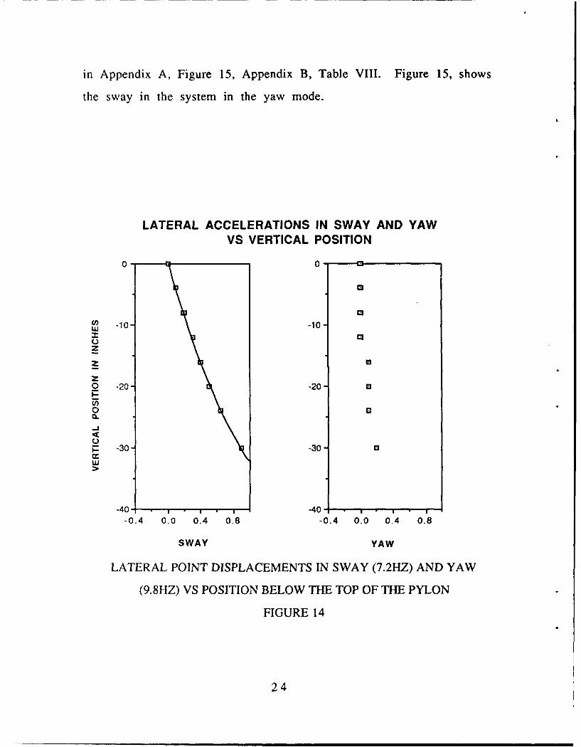
in Appendix A, Figure 15, Appendix B, Table VIII. Figure 15, shows
the sway in the system in the yaw mode.
LATERAL ACCELERATIONS IN SWAY AND YAWVS VERTICAL POSITION
0- 0-
13u) -10, -10
wzz2
0 -20 -20 m
0 00
1- -30 -30-
-40 - • , -40- , • ,-0.4 0.0 0.4 0.8 -0.4 0.0 0.4 0.8
SWAY YAW
LATERAL POINT DISPLACEMENTS IN SWAY (7.2HZ) AND YAW
(9.8HZ) VS POSITION BELOW THE TOP OF THE PYLON
FIGURE 14
24
IV. MODELING
A. GENERAL
The missile system modeling was formulated to characterize
the first modes of the missile system in pitch and heave, over the
frequency range of interest (below 50 Hz.). Analytical model
formulation requires a general knowledge of the nature of the mode
shape, the amount of damping and the number of degrees of
freedori. Rational selection of these conditions can be extracted from
experimental observations.
The experimentally observed mode shapes were discussed in
section III and summarized in Figure 13. It was observed that at
the lowest observed resonance frequency (25 Hz), the pitch mode
was in fact that of a rigid body. The heave mode observed at a
higher resonance frequency (38 Hz) has minor amount of curvature
and is not totally rigid. An analytically constraint is that the pitch
mode and the heave mode are complimentary pairs therefore the
system had to be modeled either as both rigid or as both elastic for
both modes. Since the lowest frequency is of greatest relevance to
the safe flight test envelope it can be justified to model the system as
rigid.
25

Internal damping of the system is indicated by the rate of
phase shift (as a function of frequency) between the harmonic
forcing function and the structural response. The rapid phase shift
(180 degrees over 1 Hz) noted at the 25 Hertz pitch mode was
indicative of a very lightly damped system, therefore the damping
can be neglected in the analytical model.
For each single rigid system with no deformations, the number
of degree of freedom is reduced to two for the two deformational
modes. The congruence of the motion between the components noted
in pitch at 25 Hz would seem to allow the AIM, LAU, and ADU to be
lumped together as a single mass system, thus allowing for a simple
two spring two mass model. This would provide a two degree of
freedom model, and correctly model and predict the pitch and heave
modes.
Other physical inputs into the model include mass and inertial
properties of the missile. They were obtained from actual inertial
tests on the missile performed by the NATC, Strike Aircraft Test
Directorate, (SATD) Ordnance Branch Gun Tunnel IRef. 1], and the
NWC China Lake general mass/inertia data on the AIM-9 series
missile. The LAU, and the ADU data were calculated from various
manufacturers specifications, Navy specification data and hand
measurements.
26
As a result of these observation, the Adaptor/Launcher/
Missile system can be analytically represented (in Figure 18) as a
two lumped mass system possessing no internal damping, with two
springs to provide the two degree of freedom to model the lowest
resonance of the pitch and heave modes.
B. THEORY/MODELING
A brief overview of the development of the governing
equations of motion for a two degree of freedom model is in order to
full), elucidate the mechanics, the physics, the assumptions, and
selection processes required to analytically model the system. An
exploded pictorial view of the missile system components in pitch is
provided as Appendix A, Figure 16. Additionally Appendix A, Figure
17 shows all three types of modes experienced by the missile. The
modes of interest for this analysis were the rigid modes of pitch at
25 Hertz and heave at 38 Hertz. The 33 Hertz pitch mode suggested
that an additional degree of freedom is amplified probably between
the missile/LAU and the ADU. However, the precision required to
separate out this mode was beyond the capability of the instruments
on hand for the experiment. This pitch mode was therefore not
included in the model. The 25 Hz. pitch mode is pictorialized in
Figure 18 below. A two mass "dumbbell" shape was chosen based on
the assumption that the missile, LAU and ADU were approximately
uniform in mass distribution and could reasonable be modeed as
beams. The missile, LAU and ADU move together as noted in
27

z0
k AC ~v -
LLa
A A
UJ0
28

paragraph III B above, and therefore were lumped into one two
mass "dumbbell". The dumbbell masses were separated by a distance"r" from the Center of Gravity (CG), r is matched to the radius of
gyration of the system to model the rotational inertia. The pylon was
modeled as a rigid body and the sway braces (the weak link) become
the springs (k, and k2 ) which support the dumbbell. These
hypothetical springs were separated by distances x1 and x2 . The
vertical displacement of the system in heave is denoted as z and the
rotation is accounted for by the Theta (0). The specific motions are:
in heave under rigid body assumption:
01 = 02= 0 y
0 =0 y=0 =0
in pitch also under rigid body assumption:
=02= 0Y
z(x=0)=0 at the CG
For a general combined heave and pitch the equation of motion
can be developed from the summation of moments equal to the
angular acceleration:
Iy = IyyOy
(nr2y + F ix 1 - F 2x2 = x3F 0Sin(cot)
29

where
x:= Location of applied harmonic load with amplitude FO
F2 =k2z + x2 Tan (0,)] and F = kj[z - xTan (0,)]
The small angle theorem allows the substitution:
Tan (0,)= 01 = 0 Tan (0.)= 02 = 0Y
For the rotational equation of motion this is reduced to:
(mr2)6" - x lk z + x10y)+ x-k4z + X20y)= X3FoSin(ot)
This leaves a differential equation of motion based on the
moment balance in terms of 0 and x
____ ____ x1k) _ __ _
x+k +( x 2k X 3+ kI+ 0y+ -x =k -1)2F Sinkcot)Mr" [ _ " mrn ni t (Eqn 1)
A similar derivation based on the sumrnmation of forces equal to
linear acceleration yields:
.. + [(k, +4k21] [(X2 k2 -x 1k 1) ~ Firktz + m Z+ 0- = -Fo(S i ncot0n ni J (Eqn 2)
30

These two coupled differential equations describe the motion of
a system coupled in pitch and heave. They must be solved
simultaneously.
The complementary solutions to these two equations are of the
forms:
z = z0 Cos(c)t)
OY= 0Y Cos(Cot)
These will yield the solutions:
X1 .__...__ J 2 0 00 + xk2 x 0 --'-- 0
and
{[(X l 2 -k ,xl l O 2 ) 0k+ k } X 0= Omr2
When theses two equations are simultaneously solved and
simplified the resulting equations are fourth order in the angular
velocity co
+ m4 f(kl+k2) (xjk+x2k2 )\2 + [(kl+k 2)]r(x kl+x2k2)] [(xlkl+x2k0]2m r =0
CO + .nr2 + k- m J 2 ] nirJJ2
3 1

there are no cross coupled (odd) terms in co in the absence of
damping. A variable change yields two roots giving four coupled
frequencies; two positive and two negative. The two negative roots
have no physical meanings , leaving the two real roots of the angular
velocity o
222 1 2 (k2 + (k 1+k2) (+ Iklkk2) [(xlkl+X2k2)
o" + m 0O III 11m m MM
When the experimentally measured resonance frequencies are
expressed in terms of o , the appropiated spring constants k, and k2
for the model can be obtained from the above two equations.
Considerable simplifications is possible when the equations of motion
are uncoupled under the condition:
x-k 2 - x1k1 = 0
This condition simultaneously drives the coefficient of the z
term in Eqn I to zero and the 0 term in Eqn 2 to zero , and the
complementary solutions become:
[(x k 1+x 2k2]Y 2 0=
mr
x±(k lk2)]oX+ x x=0
32

When these two equations are solved simultaneously they
yield the uncoupled equations of motion for the undamped system as
described above.
For motions in heave:
2 (kl+k 2)m
For motions in pitch:
21y2 k 2 k2 Y'kI + Y2k2
m r
When combined with the decoupling condition they create
three equations and four unknowns. This is not a problem if we can
arbitrarily place one of the springs at any given "y" position and
solve for the other y and the k's which make that assumption work.
That is in fact the case, as can be seen tabulated in Table X below, in-
which y1 was varied over a small range and the associated Y2 and k1
and k? were calculated to support that assumption.
C. MODEL SELECTION
As can be seen in Table X, and graphically in Appendix A,
Figure 19, there are several combinations of this model which could
accurately portray the motion of this system. The model selected
combined the missile, LAU, and ADU together as a two lump mass
"dumbbell", having the same mass and inertial properties as they did
separately. These lump masses were connected by a
33

Table X
Variation of Parameters to Verify Position Assumptions
ASSUMED CALCULATED CALCULATED CALCULATEDOPTION Y1 k1 Y2 k2
(FT) (KLB/FT) (FT) (LB/FT)
1 1.599 274 1.599 2742 0.256 437 1 111.83 1 111.8 0.256 4374 0.127 516 2 33
massless rigid rod of length 4.86 ft. and Yi was selected equal to Y2 as
physically the sway braces and lugs are nearly equal distance from
the CG about which the missile pitches. The damping was assumed
negligible due to the rapid shift seen in the 25 Hz mode. These
assumptions and parameters yield the model depicted in Figure 20
below.
34

0
'cod
;00X00
X0
X 000,002
X
0,0 V35

V. CONCLUSIONS
A. TEST SYSTEM
Within the scope of these tests, the GVT and shaker system are
satisfactory for longitudinal excitation of structural systems, such as
missiles, at frequencies up to approximately 50 Hz. Beyond 50 Hertz
the fundamental mode of the GVT itself (approximately 53 Hz.,
T=.019 sec) may cause pollution of data, and additional stiffening of
the system may be required.
GVT lateral response is unsatisfactory, due to base support
structural deficiencies resulting in low frequency lateral motion
under horizontal excitation of test articles. The system was designed
for the longitudinal excitation of test articles, and therefore must be
modified and stiffened, prior to performing realistic lateral excitation
on a pylon/missile model. Alternatives to redesign involve reading,
analyzing, and removing the structural motion from the test data,
caused by the motion of the GVT.
The accelerometers used, PCB model 288A 11, were
piezoelectric vice piezoresistive and were unsatisfactory for low
frequency (below 5 hertz) response due to low frequency distortion
and cutoff.
The EXACT function generator was incapable of fine tuning of
frequencies, especially above about 35 Hertz, and was designed for
single frequency inputs and not full spectrum inputs.
36

B. MISSILE SYSTEM
The primary modes and frequencies of concern on the P-3 are
the "outer wing bending mode" from 4.7-8 Hertz, and the "outer wing
torsion mode" from 17-22 Hertz. The variation goes proportionally
with fuel and stores loadings. Within the scope of this test, the first
fundamental longitudinal dynamic response frequency (25 Hertz) of
the single rail AIM-9 missile system is sufficiently above the outer
wing torsion mode of the airplane, even in the worst fuel stores case,
that it is compatible on the outboard wing stations (numbers 9 and
18) of the P-3 series airplane for in-flight flutter tests, through out
the limits of the basic airframe.
Within the scope of this test the torsional spring-mass model of
the missile system described above, satisfactorily models the single
rail AIM-9 missile system at the first rigid mode frequencies in pitch
and heave.
37

VI. RECOMMENDATIONS
A. TEST SYSTEM
Modify the test structure to provide stiffening for lateral
excitations of the test article. The entire structure could be stiffened
by replacing the lower 3/16 inch skin by a much thicker skin,
something on the order of 1/2 inches. Other avenues of approach
include internal transverse bracing, between the three internal cross
stiffener "I" beams (Appendix A, Figure 21), or a complete redesign
of the structure.
The two piezoelectric accelerometers used for data collection
should be replaced with 5 or 6 piezoresistive accelerometers so as to
ensure no low frequency (below 5 Hz.) distortion and allow for the
integration of the SD-380 Spectral Analyzer, in the 4-channel mode.
The SD-380 Spectral Analyzer should be integrated in to the
data collection system, and linked to the IBM PC/AT with the ENTEK
Corporation's EMODAL, modal analysis software package. Both of
these items are currently on board the Aero department, and could
be integrated into the system to automate the collection, analysis,
post processing, and generate multiple degrees of freedom modeling,
of the vibration data. These will be needed for the dual rail missile
installation tests.
38

The EXACT function generator should be replaced by one of
finer frequency agility and precision, so that all modes and phase
shifts within the frequency band of interest can be defined to a finer
degree. The replacement must be capable of providing broad band as
well as discrete inputs to the exciter.
A calibrated tap hammer should be purchased to augment the
function generator and validate data.
B. MISSILE SYSTEM
NAVAIR-530, following review of the test results, provide the
Naval Air Test Center, Force Warfare Aircraft Test Directorate with
the appropriate flight clearances to carry the AIM-9 missile in a
single rail/single missile arrangement on wing station 9 and 18, for
flutter testing, envelope expansion, and separation tests throughout
the limits of the basic air frame. The inflight flutter test should be
carried out prior to LBA envelope expansion on station 9. A step
down, three altitude profile, at 30000 ft. 20000 ft, and 8000 ft out
to Vne, followed by a Mach limit dive will provide total envelope
coveraoge, and can be completed in a single flight evolution. Lateral,
longitudinal, and directional, step inputs should be done at 20-25
knot increments (5-10 knot increments at the faster points)
throughout the envelope.
39

APPENDIX A
ELECTRONICS RACK
FIGURE 2
40

Si
SHAKER MOUNTING BEAMS
FIGURE 4
41

01
CD
Lo 0W0
Z *oo
*l 0 ND DJ
<C~ ~0 ~ f
oz0
CC.
0(/
L 0 Z.
LL Lf4LL0 0 ~c/) LLI--U-
z wo00000 00)0.a.
0 0
C*
42

0
.o)D0
0c
z wW
ww
W0 _j Lf)
LL. C0n
00 0K U)
0 00
<0i
00
0~
0 0
INMJ30V~dsia a3ZI1VV4IION
43

co w Cl)-j > 1W
I-iCl)
w ML
(0
0U WDZ
Q I . IF-wz uj Wz Z LLZm rr
U...
LL< wo0
z Zj
0 0
0n 2
0 0C
~\ 0 aD C C;, 0
IN3IA9OV~dSia a3ZI1VIUN
44

U'
OD
UA0j
cC,
(niiCOWLn
0Cl) Uj _j wn L
z 0 cr
LU
0>
z.z z zP0
000
1N3W3J3V~dsia a3zIIVW8l0N
45

0elj
< < 0
z -0
*EZ zw
x0n
LL.-
LL
0 0 U, = -
z- Z
LL0 01a
00
1N~J~V~dIGG~Z1V/'JIz
460

z0
CNJ N
0
N+
I> C/)
4 x+*
47

C',
IL
N 1%
+0 'j
o
-
c',LU
>UIj
R
x2
za
48

k 1 k2 274,0oob0f =-.59ft1=274,000b/f t k2 =274,000 b/ftXl= 1.59 ft Xi -1.59 ft
k= 4 3 7 ,0 0 0 lb/ft k2 =111,800 lb/ft
x1=0.256 ft x -1 ft1 2
k1 111,800 lbf=fk437,000 lb/ftx 1 = 1 ft x =-0.256 ft
k1 =51 6,oo0 lb/ft Jf k2 =33,000 lb/ft
X1= 0.127 ft x2 =-2 ft
SPRING PARAMETERS VARIATIONSALL GIVING THE SAME MODAL RESPONSES
FIGURE 19
49

APPENDIX B
Table I
Accelerometer
Sensitivity Calibrations
SENSITIVITY CALIBRATION
PERIOD ACCEL 'A' ACCEL 'B'(SECONDS) (UNITS) (UNITS)
0.250 0.232 0.1820.240 0.232 0.1820.230 0.232 0.1800.220 0.232 0.1800.210 0.232 0.1800.200 0.232 0.1780.190 0.232 0.1780.180 0.232 0.1760.170 0.232 0.1740.160 0.232 0.1720.150 0.232 0.1730.140 0.232 0.1720.130 0.232 0.1760.120 0.232 0.1760.110 0.232 0.1760.100 0.232 0.1780.090 0.232 0.1780.080 0.232 0.1770.070 0.232 0.1770.060 0.232 0.1770.050 0.232 0.1880.040 0.232 0.1880.030 0.232 0.1700.020 0.232 0,1730.010 0.232 0.180
50

Table II
Normalized Component Point
Accelerations in the Vertical at 24.4 Hertz
24.36 HZPOSITION VERTICAL ACCEL VERTICALACCEL VERTICAL ACCEL
AFT FROM NOSE OF MISSILE ADU-299 LAU-7A AIM-9(INCHES) (UNITS) (UNITS) (UNITS)
104.000 -1.750100.000 -1.00087.750 -0.85086.000 -0.65075.500 -0.500 -0.70070.000 -0.250 -0.25063.250 -0.50060.000 -0.10058.000 -0.40056.000 -0.35051.000 -0.17050.000 0.000 0.00046.000 0.00042.000 0.00040.000 0.10038.750 0.08030.000 0.300 0.38026.500 0.400 0.43026.00024.000 0.55022.000 0.60020.000 0.70018.000 0.73016.000 0.75014.250 0.550 0.80010.000 1.0006.000 0.950 1.0502.000 1.100
-2.000 1.250
51

Table III
Normalized Component Point
Accelerations in the Vertical at 25.6 Hertz
24.36 HZPOSITION VERTICAL ACCEL VERTICALACCEL VERTICAL ACCEL
AFT FROM NOSE OF MISSILE ADU-299 LAU-7A AIM-9(INCHES) (UNITS) (UNITS) (UNITS)
104.000 -1.750100.000 -1.00087.750 -0.85086.000 -0.65075.500 -0.500 -0.70070.000 -0.250 -0.25063.250 -0.50060.000 -0.10058.000 -0.40056.000 -0.35051.000 -0.17050.000 0.000 0.00046.000 0.00042.000 0.00040.000 0.10038.750 0.08030.000 0.300 0.38026.500 0.400 0.43026.00024.000 0.55022.000 0.60020.000 0.70018.000 0.73016.000 0.75014.250 0.550 0.80010.000 1.0006.000 0.950 1.0502.000 1.100
-2.000 1.250
52

Table IV
Normalized Component Point
Accelerations in the Vertical at 34 Hertz
33.3 HZ _______
POSITION VERTICAL ACCEL VERTICAL ACCEL jVERTICAL ACCELAFT FROM NOSE OF MISSILE ADU-299 LAU-7A AIM-9
(INCHES) (.U N I TS) (UNITS) (UNITS)
104.000 1.380100.000 0.72087.750 0.500 0.50086.00075 .500 0.39070.000 0.220 0.220 0.31063.250 0.22056.0 0051.00050.000 0.000 0.000 0.06040.000 -0-08329.000 0.19026.500 -0.280 -0.28026 .00016.00014.250 -0.440 -0.56010.000 -0.6708.000 -0.500 -0.7206.0004.000 -0.830
-2.000 __ _ _ _ _ _ _ _ _ _ _-1.000
53

CD CD C
>W 00
<A *C
5 CV a) ) 4 )
< 0c0o
N _ _ a)_ _ _ _ _ 0
< 0)U-) ') CLIE a) CV) Y)0
>O UJ 0) 0 0 ~(
E >U
<C'ja) C\j L) (Y)C<E o Ci - CY) 0) ) LO
i< 0 0 0 0 0 00q l Cj CY
0>0 (-)AAL VCCD
C0 )LA CO CO CJ CO 03cC)CA.
wLU 00 )) C 0000 C00 C)Z
w
m~ C) 00C0C0000CD0 0CLU2 a)000o 00000000o0: o )
0 Q~J C;00000,000*
54

Table VI
Normalized Component Point
Accelerations in the Vertical at 52.5 Hertz
POSITION AFT 52.5 HZOFTHE AIM-9
MISSILE NOSE NORMAUZED(INCHES) ACCEL
99.999 0.57188.000 0.21482.000 0.00076.000 -0.42970.00064.000 -0.71452.00050.000 -1.00040.00030.00027.000 -0.57120.000 -0.21415.000 0.28610.0002.000 0.857
55

Table VII
Normalized Component Lateral Accelerations
in Sway and Yaw at the Missile System Center of Gravity
LATERAL ACCELERATIONSVERTICAL POSITION IN SWAY IN YAW
DOWN FROM THE TOP OF THE PYLON AT 7.2 HERTZ AT 9.8 HERTZ(INCHES) (UNITS) (UNITS)
0.000 0.000 0.000-4.000 0.100 0.000-8.000 0.200 0.000
-12.000 0.300 0.000-16.000 0.400 0.100-20.000 0.500 0.100-24.000 0.650 0.100-30.000 0.900 0.200
56

Table V1II
Normalized Component Lateral Accelerations in Yaw
at 9.8 Hertz
_____ _____ 9.8 HERTZ _ _ _ _ _ _
POSITION LATERAL ACCEL LATERAL ACCEL LATERAL ACCELAFT OF THE NOSE OF THE MISSILE ADU-299 LAU-7 AIM-9
(INCHES) (UIS) (UNITS) (UNITS)
104.000 0.700100.000 0.70087.750 0.60086 .00075.500 0.400 0.40070.0 0063.250 0.300 0.250 0.20056. 00051.000 0.05050 .00040.000 -0.150 -0.300 -0.30029.000 -0.25026 .500 -0.500 -0.50026. 00014.250 -0.700 -0.75010.0006.000 _ _ _ _ _ _ _ _ _ _ _ _ _ _ _ _ _ _ _ _
57

APPENDIX C
TEST SYSTEM
TEST STRUCTURE
The test structure is situated on the isolation floor in the
basement laboratory of Halligan Hall at the Naval Post Graduate
School in Monterey California. A picture of this structure is provided
as Figures 1 and 16.
END ON VIEW OF THE GVT
FIGURE 21
58

It utilizes two of the strong backs anchored in the west side of the
floor for its primary support. The GVT was constructed mostly of
prefabricated 5, 10, and 15 foot eight-by-eight inch aluminum "I"
beams, which were designed to be compatible with the strong backs
and isolation floor mounting bolts. Where parts were not available
they were fabricated in house, at the machine shop in Bldg 214. The
structural portion of the GVT is basically an open rectangle in form,
with two parallel 15 foot overhead 8 x 8 inch "I" beams supported 7-
1/2 feet above the floor at one end by the strong backs and the other
by two vertically mounted 10 foot, 8 x 8 inch "I" beams. These
overhead beams are separated by five feet, the distance between the
strong backs, and are oriented with the flanges parallel to the floor.
Between the overhead beams are three 5 foot 8 x 8 inch "I" beams
mounted perpendicular to the overheads, parallel to the floor and
separated from each other by approximately 18 inches.These act as
stiffener and mounting beams. The two outer beams are oriented
with the web parallel to the floor, while the middle beam, which was
the main mounting support for the pylon and missile system, was
oriented with the flanges parallel to the floor. On this middle beam,
extra stiffening of the flanges is accomplished with triangular
doubler plates at every intersection, flange to flange, with the
overhead beams. A picture of the internal structure is provided
below. An upper and lower skin of 3/16 inch 2024 T-6 aluminum
was then added to "close the box" and provide rigidity in shear. This
59

particular aluminum was chosen because of its availability, vice any
special properties it may contain. A stiffening cross member was also
installed between the two 8 x 8 inch vertical column supports, at the
east end, opposite the strong backs. The initial structure was not
stiffened in any way over the basic frame and skinned center
section. Upon initial excitation of the missile in pitch, a structural
resonance began at approximately 13-14 Hz that was not only
audible throughout the lab but visible to the naked eye, and caused
tools and parts to vibrate off of the structure. Using Rayleigh's
principle, the nodes were split twice, almost in half each time.
Physical constraints within the space precluded exact bifurcation
however the initial fundamental should in theory have quadrupled
to 54 Hz. This was in fact nearly the case in that the new resonant
frequency of the overhead structure went up to approximately 52.5
Hz. The stiffeners used included 3/8 inch threaded rigid rod and 2-
1/4 inch diameter gas pipe. The stiffeners are clearly visible in
Figure 17.
The structure was designed to provide minimal motion in the
frequency range of interest (up to 50 Hz) to longitudinal test member
excitation. There was no stiffening of the internal structure to allow
for lateral excitation without motion of the structure.
60

MNERNAL STRUCTURE OF THE GVT
FIGURE 22
61

TEST EQUIPMENT
General
The major components of the test equipment were the: Breul
and Kjaer Exciter Model 4801; Breul and Kjaer Mulit-Purpose Head
Model 4812; Bruel and Kjaer Amplifier Model 2707; EXACT Function
Generator; and two PCB Impedance Heads Model 288All, and their
associated amplifiers. Each of these components is briefly discussed
below. The general set up is shown in the System V Instructions
Manual [Ref. 1], available from any B&K factory representative.
B&K Exciter Model 4801
The Model 4801 exciter was designed to be combined with any
one of several Exciter Heads to create a complete exciter assembly
capable of generating up to 100 pounds of force. The exciter was
chosen for no other reason than its immediate availability. The
exciter uses 208 volt, three phase, Delta power transformed to 380
volt, three phase Wye power. It weighs approximately 180 pounds
but can be positioned at any angle to provide optimum flexibility and
use. With the multi purpose head, the exciter is capable of
displacements up to 0.5 inches and has an internal natural frequency
of 7200 Hertz and the base has a natural frequency at about 10-14
lertz. A more detailed description of the exciter is available in the
Instructions and Applications booklet, [Ref. 11 for the Type 4801
Exciter available from the Bruel and Kjaer factory representative.
62

B&K General Purpose Exciter Head Model 4812
The Model 4812 exciter head was designed to provide a low
distortion operating band from DC to 10000 Hertz when mated to the
Model 4801 Exciter body and the Model 2707 Amplifier. The 'g' loads
available for testing vary with the test frequency and run from a low
of zero in the DC range to 100 'g' at 150-160 Hertz. More detailed
information on the Type 4812 Head is available in the Instructions
and Applications booklet for the Type 4812 General Purpose Head,
[Ref. 2], from the B&K factory representative.
B&K Power Amplifier Type 2707
The Model 2707 Amplifier was designed to provide proper
power and protection to the Exciter, Model 4801. Protective circuits
include: signal ground fault; power phase protection; over
temperature; displacement; over current; and wave form clipping
indications. A more detailed description of the Amplifier unit is
available in the Manufactures Instruction Manual for the Power
amplifier Type 2707 [Ref. 3], available from the B&K factory
representative.
EXACT Function Generator
The EXACT function generator Model 340,utilized for the tests
was resurrected from other projects. It is capable of providing
various wave forms over a fairly broad range of frequencies. It is not
63

capable of fine tuning on desired frequencies especially above about
30 Hertz, nor is it capable of amplitude variation of any wave form.
64

LIST OF TABLES
I. Accelerometer Sensitivity Calibrations
I. Normalized Component Point Accelerations in the Vertical at
24.4 Hertz
III. Normalized Component Point Accelerations in the
Vertical at 25.6 Hertz
IV. Normalized Component Point Accelerations in the Vertical at
34 Hertz
V. Normalized Component Point Accelerations in the Vertical at
38 Hertz
VI. Normalized Component Point Accelerations in the Vertical
at 52.5 Hertz
VII. Normalized Component Lateral Acceleration in Sway and Yaw
at the Missile System Center of Gravity
VIII.Normalized Component Lateral Accelerations in Yaw at 9.8
Hertz
IX. Sway Pollution in Yaw Mode at 9.8 Hertz
X. Variation of Parameters to Verify Position Assumptions
65

LIST OF FIGURES
1. SIDE VIEW OF THE GROUND VIBRATION TEST STRUCTURE
2. ELECTRONICS RACK
3. EXCITER/SHAKER ASSEMBLY
4. SHAKER MOUNTING BEAMS
5. SINGLE AIM-9 MISSILE ASSEMBLY
6. GENERAL CASE FOR MISSILE SYSTEM MODEL
7. MULTIPLE LUMPED MASS MODEL
8. COMPONENT'S POINT VERTICAL DISPLACEMENT VS
LONGITUDINAL POSITION (24.4 HZ)
9. COMPONENT'S POINT VERTICAL DISPLACEMENT VS
LONGITUDINAL POSITION (25.6 HZ)
10. COMPONENT'S POINT VERTICAL DISPLACEMENT VS
LONGITUDINAL POSITION (34 HZ)
11. COMPONENT'S POINT VERTICAL DISPLACEMENT VS
LONGITUDINAL POSITION (38 HZ)
12. COMPONENT'S POINT VERTICAL DISPLACEMENT VS
LONGITUDINAL POSITION (52.5HZ)
13. MISSILE MODES FOR SINGLE RAIL AIM-9
24.4/38/52.5 HERTZ
14. COMPONENT'S POINT LATERAL DISPLACEMENT IN
SWAY AND YAW VS POSITION
BELOW TIlE TOP OF THE PYLON
66

15. COMPONENTS POINT LATERAL DISPLACEMENT IN YAW VS
LONGITUDINAL POSITION (9.8 HZ)
16. MISSILE SYSTEM COMPONENT BREAKDOWN
PITCH AT 25 HERTZ
17. AIM-9 MISSILE MODE SHAPES
18. MISSILE SYSTEM SPRING MASS MODEL
19. SPRING PARAMETERS VARIATIONS ALL GIVING
THE SAME MODAL RESPONSES
20. SPRING MASS MODEL
21. END ON VIEW OF THE GVT
22. INTERNAL STRUCTURE OF THE GVT
67

LIST OF REFERENCES
1. LCDR J.B. Hollyer, P-31AIM-9 Integration Flight Test Project
Notebook. Naval Air Test Center, Force Warfare Test
Directorate Code 52B, Patuxent River, Md. June 1988.
2. Bruel & Kjaer, Instruction Manual, Vibration Exciter System V.
Orboe Print, Copenhagen Denmark, 1971.
3. Bruel & Kjaer, Instructions and Applications, Exciter Body Type
4801. Orboe Print, Copenhagen Denmark, 1971.
4. Bruel & Kjaer, Instructions and Applications. General Purpose
Head Type 4812, Orboe Print, Copenhagen Denmark, 1971.
5. Bruel & Kjaer, Instruction Manual, Power Amplifier Type 2707,
Orboe Print, Copenhagen Denmark, Aug. 1982.
68

INITIAL DISTRIBUTION LIST
1. Library, Code 0142 2Naval Postgraduate SchoolMonterey, Ca. 93943-5000
2. Defense Technical Information Center 2Cameron StationAlexandria, Va. 22304-6145
3. Commander (AIR-5114B)Attn- CDR NewsomeNaval Air Systems Command 2Washington, D.C. 23061-0001
4. Commander (AIR-5302)Attn. Mr. Geo. MagossNaval Air Systems CommandWashington, D.C. 23061-0001
5. Department Chairman 2Department of Aeronautics and AstronauticsNaval Postgraduate SchoolMonterey, Ca. 93943-5000
6. Commander Naval Air Test Center 5Mr. Tim TwiggFWATD Code 52BNATC Patuxent River, Md. 20670
7. Commander Patron 31Attn: Dr. Hank Smith Code 23SNAS Moffett Field,Ca. 94035
69

8. LCDR John Hollyer USN 52616 QuenbyHouston, Texas 77005
9. Professor Babe Wu, Code 67WT 5Department of Aeronautics and AstronauticsNaval Postgraduate SchoolMonterey, Ca. 93943-5000
1 0 Dr. LouV. Schmidt, Code 67SC 2Department of Aeronautics and AstronauticsNaval Postgraduate SchoolMonterey, Ca. 93943-5000
70