group 11c engine mechanical
TRANSCRIPT

11C-1
GROUP 11C
ENGINE MECHANICAL
<2.4L ENGINE>CONTENTS
GENERAL DESCRIPTION. . . . . . . . . 11C-2
ENGINE DIAGNOSIS. . . . . . . . . . . . . 11C-3
SPECIAL TOOLS. . . . . . . . . . . . . . . . 11C-4
ON-VEHICLE SERVICE. . . . . . . . . . . 11C-8DRIVE BELT TENSION CHECK. . . . . . . . . 11C-8AUTO-TENSIONER CHECK . . . . . . . . . . . 11C-8VALVE CLEARANCE CHECK AND ADJUSTMENT . . . . . . . . . . . . . . . . . . . . . . 11C-10ROCKER ARM PISTON OPERATION CHECK . . . . . . . . . . . . . . . . . . . . . . . . . . . . 11C-11IGNITION TIMING CHECK. . . . . . . . . . . . . 11C-12IDLE MIXTURE CHECK . . . . . . . . . . . . . . . 11C-13CURB IDLE SPEED CHECK . . . . . . . . . . . 11C-14COMPRESSION PRESSURE CHECK. . . . 11C-15MANIFOLD VACUUM CHECK . . . . . . . . . . 11C-16
ENGINE ASSEMBLY. . . . . . . . . . . . . 11C-17REMOVAL AND INSTALLATION . . . . . . . . 11C-17
CRANKSHAFT PULLEY . . . . . . . . . . 11C-25REMOVAL AND INSTALLATION . . . . . . . . 11C-25
CAMSHAFT AND VALVE STEM SEAL. . . . . . . . . . . . . . . . . . . . . . . . . . 11C-27
REMOVAL AND INSTALLATION . . . . . . . . 11C-27
OIL PAN . . . . . . . . . . . . . . . . . . . . . . . 11C-34REMOVAL AND INSTALLATION . . . . . . . . 11C-34INSPECTION. . . . . . . . . . . . . . . . . . . . . . . . 11C-36
CRANKSHAFT OIL SEAL . . . . . . . . . 11C-37REMOVAL AND INSTALLATION . . . . . . . . 11C-37
CYLINDER HEAD GASKET . . . . . . . . 11C-41REMOVAL AND INSTALLATION . . . . . . . . 11C-41
TIMING BELT . . . . . . . . . . . . . . . . . . . 11C-48REMOVAL AND INSTALLATION . . . . . . . . 11C-48INSPECTION. . . . . . . . . . . . . . . . . . . . . . . . 11C-60
SPECIFICATIONS . . . . . . . . . . . . . . . 11C-62FASTENER TIGHTENING SPECIFICATIONS. . . . . . . . . . . . . . . . . . . . 11C-62SERVICE SPECIFICATIONS . . . . . . . . . . . 11C-63SEALANTS . . . . . . . . . . . . . . . . . . . . . . . . . 11C-64

GENERAL DESCRIPTIONENGINE MECHANICAL <2.4L ENGINE>11C-2
GENERAL DESCRIPTIONM1111000100497
The 4G69 (2.4L) engine is an in-line four cylinder engine. The cylinder numbers are assigned as 1 − 2 − 3 − 4 from the front of the engine (timing belt side). This engine is fired in the order of the 1, 3, 4 and 2 cylinders.ITEM SPECIFICATIONType In-line SOHCNumber of cylinders 4Bore mm (in) 87 (3.43)Stroke mm (in) 100.0 (3.94)
Total displacement cm3 (cu in) 2,378 (145.1)
Compression ratio 9.5Firing order 1 − 3 − 4 − 2Counterbalance shaft EquippedValve timing Intake valve Opens (BTDC) 10° <Low speed cam A>
12° <Low speed cam B>24° <High speed cam>
Closes (ABDC) 42° <Low speed cam A>44° <Low speed cam B>68° <High speed cam>
Exhaust valve Opens (BBDC) 58°Closes (ATDC) 18°
Lubrication system Pressure feed, full-flow filtrationOil pump type Involute gear type
TSB Revision

ENGINE DIAGNOSISENGINE MECHANICAL <2.4L ENGINE> 11C-3
ENGINE DIAGNOSISM1111000700284
SYMPTOM PROBABLE CAUSE REMEDYCompression is too low
Blown cylinder head gasket Replace the gasketWorn or damaged piston rings Replace the ringsWorn piston or cylinder Repair or replace the piston and/or the
cylinder blockWorn or damaged valve seat Repair or replace the valve and/or the
seat ringDrop in engine oil pressure
Engine oil level is too low Check the engine oil levelMalfunction of engine oil pressure switch Replace the engine oil pressure switchClogged oil filter Install a new filterWorn oil pump gears or cover Replace the gears and/or the coverThin or diluted engine oil Change the engine oil to correct viscosityStuck (opened) oil relief valve Repair the relief valveExcessive bearing clearance Replace the bearings
Engine oil pressure too high
Stuck (closed) oil relief valve Repair the relief valve
Noisy valves Incorrect valve clearance Adjust valve clearanceThin or diluted engine oil (low engine oil pressure)
Change the engine oil
Worn or damaged valve stem or valve guide
Replace the valve and/or the guide
Connecting rod noise/main bearing noise
Insufficient oil supply Check the engine oil levelLow engine oil pressure Refer to engine oil pressure drop
symptoms aboveThin or diluted engine oil Change the engine oilExcessive bearing clearance Replace the bearings
TSB Revision

SPECIAL TOOLSENGINE MECHANICAL <2.4L ENGINE>11C-4
SPECIAL TOOLSM1111000600663
TOOL TOOL NUMBER AND NAME SUPERSESSION APPLICATIONMB991958MUT-III sub assemblyA: MB991824
Vehicle communication interface (V.C.I.)
B: MB991827MUT-III USB cable
C: MB991910MUT-III main harness A (Vehicles with CAN communication system)
D: MB991911MUT-III main harness B (Vehicles without CAN communication system)
E: MB991914MUT-III main harness C (for Daimler Chrysler models only)
F: MB991825MUT-III measurement adapter
G: MB991826MUT-III trigger harness
MB991824-KITNOTE: G: MB991826 MUT-III Trigger Harness is not necessary when pushing V.C.I. ENTER key.
• Drive belt tension check• Ignition timing check• Curb idle speed check• Idle mixture check
CAUTIONMUT-III main harness B (MB991911) should be used. MUT-III main harness A and C should not be used for this vehicle.
MB991668Belt tension meter set
Tool not available Drive belt tension check [used together with scan tool (MUT-III sub assembly)]
MB991910
MB991826
MB991958
MB991911
MB991914
MB991824
MB991827
MB991825
DO NOT USE
A
B
C
D
E
F
G
DO NOT USE
B991668
TSB Revision

SPECIAL TOOLSENGINE MECHANICAL <2.4L ENGINE> 11C-5
MB991454Engine hanger balancer
MZ203827-01 When the engine hanger is used: Supporting the engine assembly during removal and installation of the transaxle assemblyNOTE: Special tool MB991454 is a part of engine hanger attachment set MB991453.
MB991527Hanger
Tool not available
MB991895Engine hanger
Tool not available
MB991928Engine hangerA: MB991929
Joint (50) × 2B: MB991930
Joint (90) × 2C: MB991931
Joint (140) × 2D: MB991932
Foot (standard) × 4E: MB991933
Foot (short) × 2F: MB991934
Chain and hook assembly
Tool not available
MB990767Front hub and flange yoke holder
MB990767-01 Holding the camshaft sprocket
MD998719Pin
MIT308239
MD998772Valve spring compressor
General service tool
Compressing valve spring
TOOL TOOL NUMBER AND NAME SUPERSESSION APPLICATION
B991454
B991527
MB991895
B991928
A
B
C
D
E
F
SLIDE BRACKET (HI)
B990767
D998719
MD998772
TSB Revision

SPECIAL TOOLSENGINE MECHANICAL <2.4L ENGINE>11C-6
MD998774Valve stem seal installer
MD998774-01 Valve stem seal installation
MD998713Camshaft oil seal installer
MD998713-01 Camshaft oil seal installation
MD998727Oil pan remover
MD998727-01 Oil pan removal
MD998781Flywheel stopper
General service tool
• Supporting the flywheel assembly <M/T>
• Supporting the A/T drive plate <A/T>
MB990938Installer bar
MB990938-01 Crankshaft rear oil seal installation
MD998776Crankshaft rear oil seal installer
MD998776-01
MD998285Crankshaft front oil seal guide
MD998285-01 Crankshaft front oil seal installation
MD998375Crankshaft front oil seal installer
MD998375-01
TOOL TOOL NUMBER AND NAME SUPERSESSION APPLICATION
D998713
D998727
D998781
B990938
D998776
D998285
TSB Revision

SPECIAL TOOLSENGINE MECHANICAL <2.4L ENGINE> 11C-7
MD998738Adjusting bolt
MD998738-01 Supporting the timing belt tensioner arm and timing belt tensioner adjuster
MB991654Cylinder head bolt wrench (12)
General service tool
Removal and installation of cylinder head bolt
MB991367Special spanner
MB991367-01 Holding the crankshaft camshaft drive sprocket
MB991385Pin
MIT217213
MD998767Tensioner wrench
MD998752-01 Valve timing belt tension adjustment
TOOL TOOL NUMBER AND NAME SUPERSESSION APPLICATION
D998738
B991654
B991367
B991385
D998767
TSB Revision

ON-VEHICLE SERVICEENGINE MECHANICAL <2.4L ENGINE>11C-8
ON-VEHICLE SERVICEDRIVE BELT TENSION CHECK
M1111003100526
CAUTIONCheck the drive belt tension after turning the crankshaft clockwise one turn or more.1. Make sure that the indicator mark is within the area marked
with A in the illustration.2. If the mark is out of the area, replace the drive belt. (Refer to
P.11C-25).NOTE: The drive belt tension adjustment is not necessary as auto-tensioner is adopted.
AUTO-TENSIONER CHECKM1111003000239
OPERATION CHECK1. Turn OFF the engine from the idle state then check to see
that the drive belt is not protruding from the pulley width of the auto-tensioner.
2. Remove the drive belt. (Refer to P.11C-25).3. Securely insert the spindle handle or ratchet handle with a
12.7 mm (1/2-inch) insertion angle into the jig hole of the auto tensioner. Turn the auto-tensioner to the left and right to check and see that there is no threading.
4. If there are any problems in the procedure 1 or 3, replace the auto-tensioner. (Refer to P.11C-48).
5. Install the drive belt. (Refer to P.11C-25).
FUNCTION CHECKYou can verify if the auto-tensioner is defective or not by check-ing the drive belt tension..
When using scan tool MB991958Required Special Tools:• MB991668: Belt Tension Meter Set• MB991958: Scan Tool (MUT-III Sub Assembly)
• MB991824: V.C.I.• MB991911: MUT-III Main Harness B
1. Check the drive belt tension. (Refer to P.11C-8).2. Measure the drive belt tension vibration frequency by the
following procedures:
AC301702AB
INDICATOR MARK
A
AC301703
TSB Revision
ON-VEHICLE SERVICEENGINE MECHANICAL <2.4L ENGINE> 11C-9
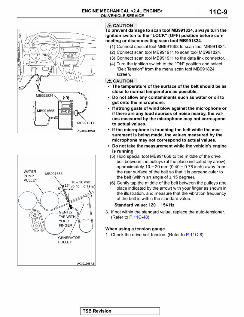
CAUTIONTo prevent damage to scan tool MB991824, always turn the ignition switch to the "LOCK" (OFF) position before con-necting or disconnecting scan tool MB991824.
(1) Connect special tool MB991668 to scan tool MB991824.(2) Connect scan tool MB991911 to scan tool MB991824.(3) Connect scan tool MB991911 to the data link connector.(4) Turn the ignition switch to the "ON" position and select
"Belt Tension" from the menu scan tool MB991824 screen.
CAUTION• The temperature of the surface of the belt should be as
close to normal temperature as possible.• Do not allow any contaminants such as water or oil to
get onto the microphone.• If strong gusts of wind blow against the microphone or
if there are any loud sources of noise nearby, the val-ues measured by the microphone may not correspond to actual values.
• If the microphone is touching the belt while the mea-surement is being made, the values measured by the microphone may not correspond to actual values.
• Do not take the measurement while the vehicle's engine is running.
(5) Hold special tool MB991668 to the middle of the drive belt between the pulleys (at the place indicated by arrow), approximately 10 − 20 mm (0.40 − 0.78 inch) away from the rear surface of the belt so that it is perpendicular to the belt (within an angle of ± 15 degree).
(6) Gently tap the middle of the belt between the pulleys (the place indicated by the arrow) with your finger as shown in the illustration, and measure that the vibration frequency of the belt is within the standard value.
Standard value: 120 − 154 Hz3. If not within the standard value, replace the auto-tensioner.
(Refer to P.11C-48)..
When using a tension gauge1. Check the drive belt tension. (Refer to P.11C-8).
AC308119AB
MB991824
MB991911
16-PIN
MB991668
AC301266AB
MB991668
10 – 20 mm(0.40 – 0.78 in)
WATER PUMP PULLEY
GENTLY TAP WITHYOUR FINGER
15˚15˚
GENERATOR PULLEY
TSB Revision
ON-VEHICLE SERVICEENGINE MECHANICAL <2.4L ENGINE>11C-10
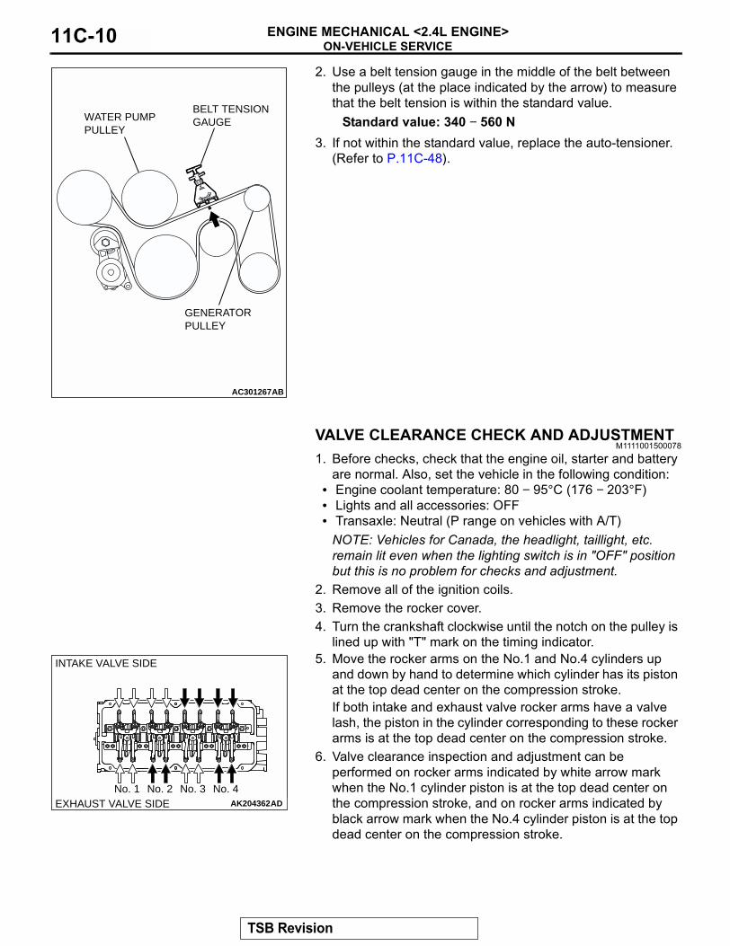
2. Use a belt tension gauge in the middle of the belt between the pulleys (at the place indicated by the arrow) to measure that the belt tension is within the standard value.
Standard value: 340 − 560 N3. If not within the standard value, replace the auto-tensioner.
(Refer to P.11C-48).
VALVE CLEARANCE CHECK AND ADJUSTMENTM1111001500078
1. Before checks, check that the engine oil, starter and battery are normal. Also, set the vehicle in the following condition:
• Engine coolant temperature: 80 − 95°C (176 − 203°F)• Lights and all accessories: OFF• Transaxle: Neutral (P range on vehicles with A/T)
NOTE: Vehicles for Canada, the headlight, taillight, etc. remain lit even when the lighting switch is in "OFF" position but this is no problem for checks and adjustment.
2. Remove all of the ignition coils.3. Remove the rocker cover.4. Turn the crankshaft clockwise until the notch on the pulley is
lined up with "T" mark on the timing indicator.5. Move the rocker arms on the No.1 and No.4 cylinders up
and down by hand to determine which cylinder has its piston at the top dead center on the compression stroke. If both intake and exhaust valve rocker arms have a valve lash, the piston in the cylinder corresponding to these rocker arms is at the top dead center on the compression stroke.
6. Valve clearance inspection and adjustment can be performed on rocker arms indicated by white arrow mark when the No.1 cylinder piston is at the top dead center on the compression stroke, and on rocker arms indicated by black arrow mark when the No.4 cylinder piston is at the top dead center on the compression stroke.
AC301267
BELT TENSION GAUGE
AB
GENERATOR PULLEY
WATER PUMP PULLEY
AK204362ADEXHAUST VALVE SIDENo. 1 No. 2 No. 3 No. 4
INTAKE VALVE SIDE
TSB Revision
ON-VEHICLE SERVICEENGINE MECHANICAL <2.4L ENGINE> 11C-11
7. Measure the valve clearance.If the valve clearance is not as specified, loosen the rocker arm lock nut and adjust the clearance using a thickness gauge while turning the adjusting screw.
Standard value (hot engine):Intake valve: 0.20 mm (0.008 inch)Exhaust valve: 0.30 mm (0.012 inch)
8. While holding the adjusting screw with a screwdriver to prevent it from turning, tighten the lock nut to the specified torque.
Tightening torque: 9 ± 1 N⋅m (80 ± 9 in-lb)9. Turn the crankshaft through 360 degree angle to line up the
notch on the crankshaft pulley with the "T" mark on the timing indicator.
10.Repeat steps (7) and (8) on other valves for clearance adjustment.
11.Install the rocker cover.12.Install the ignition coils.
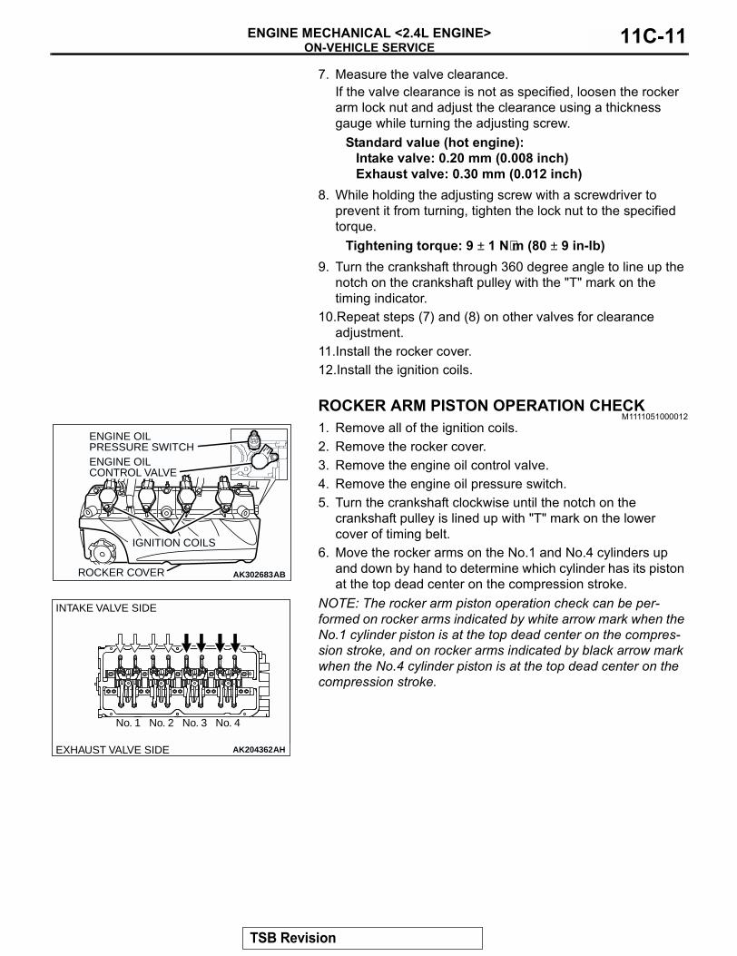
ROCKER ARM PISTON OPERATION CHECKM1111051000012
1. Remove all of the ignition coils.2. Remove the rocker cover.3. Remove the engine oil control valve.4. Remove the engine oil pressure switch.5. Turn the crankshaft clockwise until the notch on the
crankshaft pulley is lined up with "T" mark on the lower cover of timing belt.
6. Move the rocker arms on the No.1 and No.4 cylinders up and down by hand to determine which cylinder has its piston at the top dead center on the compression stroke.
NOTE: The rocker arm piston operation check can be per-formed on rocker arms indicated by white arrow mark when the No.1 cylinder piston is at the top dead center on the compres-sion stroke, and on rocker arms indicated by black arrow mark when the No.4 cylinder piston is at the top dead center on the compression stroke.
AK302683AB
ENGINE OIL PRESSURE SWITCHENGINE OIL CONTROL VALVE
IGNITION COILS
ROCKER COVER
AK204362AHEXHAUST VALVE SIDE
No. 1 No. 2 No. 3 No. 4
INTAKE VALVE SIDE
TSB Revision
ON-VEHICLE SERVICEENGINE MECHANICAL <2.4L ENGINE>11C-12
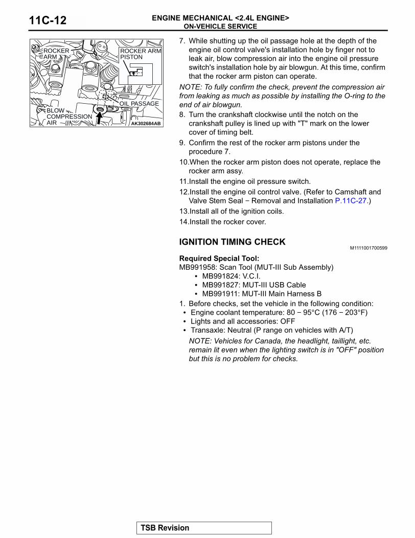
7. While shutting up the oil passage hole at the depth of the engine oil control valve's installation hole by finger not to leak air, blow compression air into the engine oil pressure switch's installation hole by air blowgun. At this time, confirm that the rocker arm piston can operate.
NOTE: To fully confirm the check, prevent the compression air from leaking as much as possible by installing the O-ring to the end of air blowgun.8. Turn the crankshaft clockwise until the notch on the
crankshaft pulley is lined up with "T" mark on the lower cover of timing belt.
9. Confirm the rest of the rocker arm pistons under the procedure 7.
10.When the rocker arm piston does not operate, replace the rocker arm assy.
11.Install the engine oil pressure switch.12.Install the engine oil control valve. (Refer to Camshaft and
Valve Stem Seal − Removal and Installation P.11C-27.)13.Install all of the ignition coils.14.Install the rocker cover.
IGNITION TIMING CHECKM1111001700599
Required Special Tool:MB991958: Scan Tool (MUT-III Sub Assembly)
• MB991824: V.C.I.• MB991827: MUT-III USB Cable• MB991911: MUT-III Main Harness B
1. Before checks, set the vehicle in the following condition:• Engine coolant temperature: 80 − 95°C (176 − 203°F)• Lights and all accessories: OFF• Transaxle: Neutral (P range on vehicles with A/T)
NOTE: Vehicles for Canada, the headlight, taillight, etc. remain lit even when the lighting switch is in "OFF" position but this is no problem for checks.
AK302684AB
ROCKER ARM PISTON
BLOW COMPRESSION AIR
OIL PASSAGE
ROCKER ARM
TSB Revision

ON-VEHICLE SERVICEENGINE MECHANICAL <2.4L ENGINE> 11C-13
CAUTIONTo prevent damage to scan tool MB991958, always turn the ignition switch to the "LOCK" (OFF) position before con-necting or disconnecting scan tool MB991958.2. Connect scan tool MB991958 to the data link connector.3. Set up a timing light.4. Start the engine and run it at idle.5. Check that the idle speed is approximately 750 r/min.6. Select scan tool MB991958 actuator test "item number 17".7. Check that basic ignition timing is within the standard value.
Standard value: 5° BTDC ± 3°8. If the basic ignition timing is not within the standard value,
check the following items:• Diagnostic output• Timing belt cover and crankshaft position sensor installation
conditions• Crankshaft sensing blade condition
CAUTIONIf the actuator test is not canceled, the forced drive will continue for 27 minutes. Driving in this state could lead to engine failure.9. Press the clear key on scan tool MB991958 (select forced
drive stop mode), and cancel the actuator test.10.Check that the actual ignition timing is at the standard value.
Standard value: Approximately 10° BTDCNOTE: Ignition timing fluctuates about ± 7° Before Top Dead Center, even under normal operating condition.NOTE: It is automatically further advanced by about 5° to 10° Before Top Dead Center at higher altitudes.
IDLE MIXTURE CHECKM1111002100415
Required Special Tool:MB991958: Scan Tool (MUT-III Sub Assembly)
• MB991824: V.C.I.• MB991827: MUT-III USB Cable• MB991911: MUT-III Main Harness B
1. Before checks, set the vehicle in the following condition:• Engine coolant temperature: 80 − 95°C (176 − 203°F)• Lights and all accessories: OFF• Transaxle: Neutral (P range on vehicles with A/T)
NOTE: Vehicles for Canada, the headlight, taillight, etc. remain lit even when the lighting switch is in "OFF" position but this is no problem for checks.
AK301038
MB991911
16-PIN
MB991827
MB991824
AB
TSB Revision

ON-VEHICLE SERVICEENGINE MECHANICAL <2.4L ENGINE>11C-14
CAUTIONTo prevent damage to scan tool MB991958, always turn the ignition switch to the "LOCK" (OFF) position before con-necting or disconnecting scan tool MB991958.2. Connect scan tool MB991958 to the data link connector.3. Check that the basic ignition timing is within the standard
value. Standard value: 5° BTDC ± 3°
4. Start the engine and increase the engine speed to 2,500 r/min for 2 minutes.
5. Set the CO, HC tester.6. Check the CO contents and the HC contents at idle.
Standard value:CO contents: 0.5 % or lessHC contents: 100 ppm or less
7. If the CO and HC contents do not remain inside the standard value, check the following items:NOTE: Replace the catalytic converter when the CO and HC contents do not remain inside the standard value, even though the result of the inspection is normal for all items.
• Diagnostic output• Closed-loop control (When the closed-loop control is carried
out normally, the output signal of the heated oxygen sensor changes between 0 − 400 mV and 600 − 1,000 mV at idle.)
• Fuel pressures• Injector• Ignition coil, spark plug• EGR system• Evaporative emission system• Compression pressure
CURB IDLE SPEED CHECKM1111003500643
Required Special Tool:MB991958: Scan Tool (MUT-III Sub Assembly)
• MB991824: V.C.I.• MB991827: MUT-III USB Cable• MB991911: MUT-III Main Harness B
1. Before checks, set the vehicle in the following condition.• Engine coolant temperature: 80 − 95°C (176 − 203°F)• Lights and all accessories: OFF• Transaxle: Neutral (P range on vehicles with A/T)
NOTE: Vehicles for Canada, the headlight, taillight, etc. remain lit even when the lighting switch is in "OFF" position but this is no problem for checks.
AK301038
MB991911
16-PIN
MB991827
MB991824
AB
TSB Revision
ON-VEHICLE SERVICEENGINE MECHANICAL <2.4L ENGINE> 11C-15
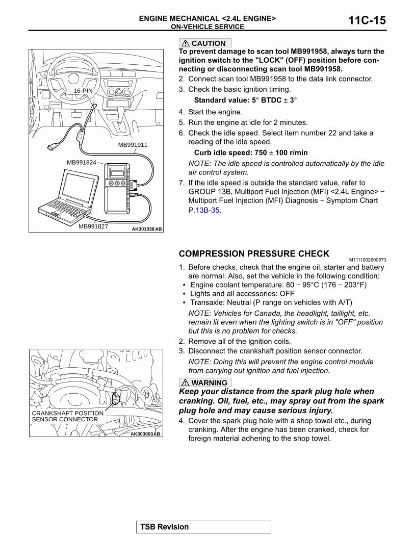
CAUTIONTo prevent damage to scan tool MB991958, always turn the ignition switch to the "LOCK" (OFF) position before con-necting or disconnecting scan tool MB991958.2. Connect scan tool MB991958 to the data link connector.3. Check the basic ignition timing.
Standard value: 5° BTDC ± 3°4. Start the engine.5. Run the engine at idle for 2 minutes.6. Check the idle speed. Select item number 22 and take a
reading of the idle speed.Curb idle speed: 750 ± 100 r/min
NOTE: The idle speed is controlled automatically by the idle air control system.
7. If the idle speed is outside the standard value, refer to GROUP 13B, Multiport Fuel Injection (MFI) <2.4L Engine> − Multiport Fuel Injection (MFI) Diagnosis − Symptom Chart P.13B-35.
COMPRESSION PRESSURE CHECKM1111002600573
1. Before checks, check that the engine oil, starter and battery are normal. Also, set the vehicle in the following condition:
• Engine coolant temperature: 80 − 95°C (176 − 203°F)• Lights and all accessories: OFF• Transaxle: Neutral (P range on vehicles with A/T)
NOTE: Vehicles for Canada, the headlight, taillight, etc. remain lit even when the lighting switch is in "OFF" position but this is no problem for checks.
2. Remove all of the ignition coils.3. Disconnect the crankshaft position sensor connector.
NOTE: Doing this will prevent the engine control module from carrying out ignition and fuel injection.WARNING
Keep your distance from the spark plug hole when cranking. Oil, fuel, etc., may spray out from the spark plug hole and may cause serious injury.4. Cover the spark plug hole with a shop towel etc., during
cranking. After the engine has been cranked, check for foreign material adhering to the shop towel.
AK301038
MB991911
16-PIN
MB991827
MB991824
AB
AK303003AB
CRANKSHAFT POSITIONSENSOR CONNECTOR
TSB Revision

ON-VEHICLE SERVICEENGINE MECHANICAL <2.4L ENGINE>11C-16
5. Set a compression gauge to one of the spark plug holes.6. Crank the engine with the throttle valve fully open and
measure the compression pressure.Standard value (at engine speed of 200 r/min): 1,560 kPa (226 psi)Minimum limit (at engine speed of 200 r/min): 1,130 kPa (164 psi)
7. Measure the compression pressure for all the cylinders, and check that the pressure differences of the cylinders are below the limit.
Limit: 98 kPa (14 psi)8. If there is a cylinder with compression or a compression
difference that is outside the limit, pour a small amount of engine oil through the spark plug hole, and repeat the operations in steps 6 to 8.(1) If the compression increases after oil is added, the cause
of the malfunction is a worn or damaged piston ring and/or cylinder inner surface.
(2) If the compression does not rise after oil is added, the cause is a burnt or defective valve seat, or pressure is leaking from the gasket.
9. Connect the crankshaft position sensor connector.10.Install the ignition coils.11.Use the scan tool to erase the diagnostic trouble codes.
NOTE: This will erase the diagnostic trouble code resulting from the crankshaft position sensor connector being discon-nected.
MANIFOLD VACUUM CHECKM1111002700558
1. Start the engine and allow it to warm up until the temperature of the engine coolant reaches 80 − 95°C (176 − 203°F).
2. Connect an engine tachometer.3. Disconnect the ventilation hose from the positive crankcase
ventilation (PCV) valve, and connect a vacuum gauge to the ventilation hose.
4. Plug the PCV valve.5. Start the engine and check that idle speed is within
specification. Then check the vacuum gauge reading.Idle speed: 750 ± 100 r/minMinimum limit: 60 kPa (18 in Hg)
AK204360
COMPRESSION GAUGE
AC
AK302373AB
VACUUM GAUGE
POSITIVE CRANKCASE VENTILATION VALVE
VENTILATION HOSE
PLUG
TSB Revision

ENGINE ASSEMBLYENGINE MECHANICAL <2.4L ENGINE> 11C-17
ENGINE ASSEMBLYREMOVAL AND INSTALLATION
M1112001000935
CAUTION*: indicates parts which should be temporarily tightened, and then fully tightened with the engine weight applied on the vehicle body.
Pre-removal Operation• Under Cover Removal.• Fuel Line Pressure Reduction [Refer to GROUP 13B,
On-vehicle Service − Fuel Pump Connector Disconnec-tion (How to Reduce Pressurized Fuel Lines) P.13B-906].
• Engine Oil Draining (Refer to GROUP 12, On-vehicle Ser-vice − Engine Oil Replacement P.12-4).
• Engine Coolant Draining (Refer to GROUP 14, On-vehicle Service − Engine Coolant Replacement P.14-25).
• Transmission Oil Draining <M/T> (Refer to GROUP 22A, On-vehicle Service − Transmission Oil Replacement P.22A-11).
• Transmission Fluid Draining <A/T> (Refer to GROUP 23B, On-vehicle Service − Transmission Fluid Change P.23B-324).
• Hood Removal (Refer to GROUP 42, Hood P.42-7).• Strut Tower Bar Removal (Refer to GROUP 42, Strut
Tower Bar P.42-12).• Engine Cover Removal (Refer to P.11C-27).• Air Cleaner Removal (Refer to GROUP 15, Air Cleaner
P.15-4).• Battery and Battery Tray Removal• Accelerator Cable Removal (Refer to GROUP 17, Accel-
erator Cable and Pedal P.17-7).• Radiator Assembly Removal (Refer to GROUP 14, Radia-
tor P.14-29).• Front Exhaust Pipe Removal (Refer to GROUP 15,
Exhaust Pipe and Main Muffler P.15-13).
Post-installation Operation• Front Exhaust Pipe Installation (Refer to GROUP 15,
Exhaust Pipe and Main Muffler P.15-13).• Radiator Assembly Installation (Refer to GROUP 14,
Radiator P.14-29).• Accelerator Cable Installation (Refer to GROUP 17,
Accelerator Cable and Pedal P.17-7).• Battery and Battery Tray Installation• Air Cleaner Installation (Refer to GROUP 15, Air Cleaner
P.15-4).• Engine Cover Installation (Refer to P.11C-27).• Strut Tower Bar Installation (Refer to GROUP 42, Strut
Tower Bar P.42-12).• Hood Installation (Refer to GROUP 42, Hood P.42-7).• Transmission Fluid Refilling <A/T> (Refer to GROUP 23B,
On-vehicle Service − Transmission Fluid Change P.23B-324).
• Transmission Oil Refilling <M/T> (Refer to GROUP 22A, On-vehicle Service − Transmission Oil Replacement P.22A-11).
• Engine Coolant Refilling (Refer to GROUP 14, On-vehicle Service − Engine Coolant Replacement P.14-25).
• Engine Oil Refilling (Refer to GROUP 12, On-vehicle Ser-vice − Engine Oil Replacement P.12-4).
• Accelerator Cable Adjustment (Refer to GROUP 17, On-vehicle Service − Accelerator Cable Check and Adjustment P.17-6).
• Fuel Leak Check• Drive Belt Tension Check (Refer to P.11C-8).• Under Cover Installation.• Front Wheel Alignment Check and Adjustment (Refer to
GROUP 33A, On-vehicle Service − Front Wheel Align-ment Check and Adjustment P.33A-7).
TSB Revision
ENGINE ASSEMBLYENGINE MECHANICAL <2.4L ENGINE>11C-18
AC308129
5.0 ± 1.0 N·m44 ± 9 in-lb
9.0 ± 2.0 N·m80 ± 17 in-lb
1
5
43
2
AB
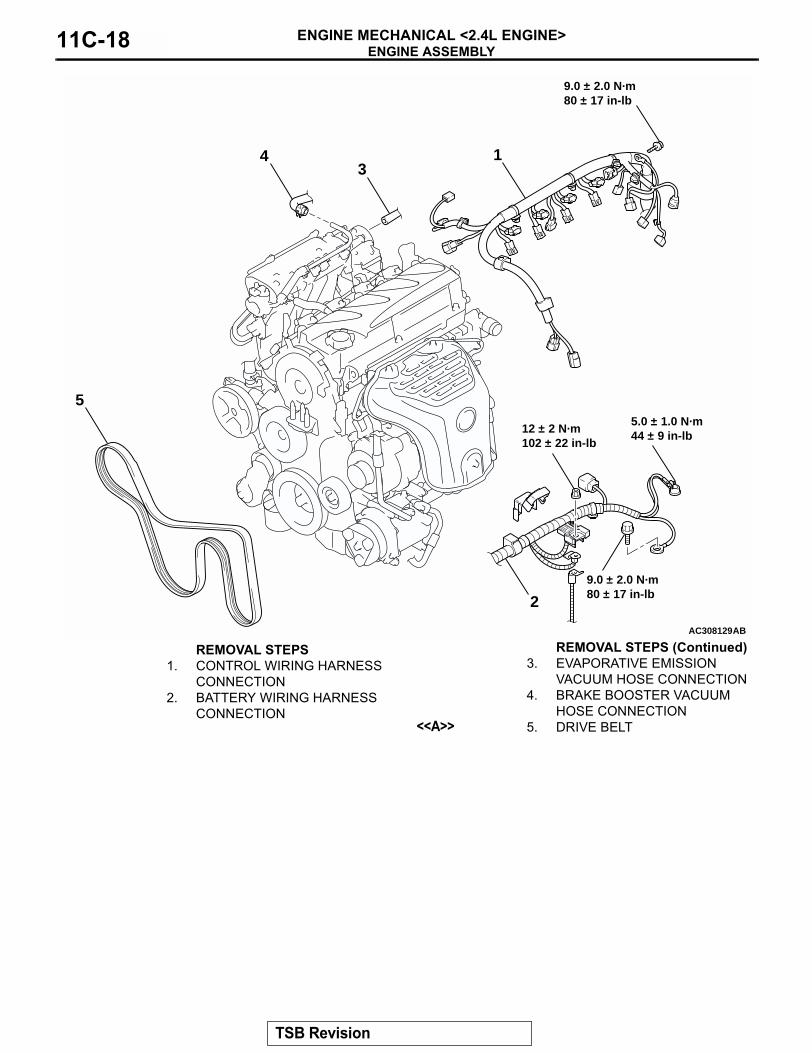
9.0 ± 2.0 N·m80 ± 17 in-lb
12 ± 2 N·m102 ± 22 in-lb
REMOVAL STEPS1. CONTROL WIRING HARNESS
CONNECTION2. BATTERY WIRING HARNESS
CONNECTION
3. EVAPORATIVE EMISSION VACUUM HOSE CONNECTION
4. BRAKE BOOSTER VACUUM HOSE CONNECTION
<<A>> 5. DRIVE BELT
REMOVAL STEPS (Continued)
TSB Revision
ENGINE ASSEMBLYENGINE MECHANICAL <2.4L ENGINE> 11C-19
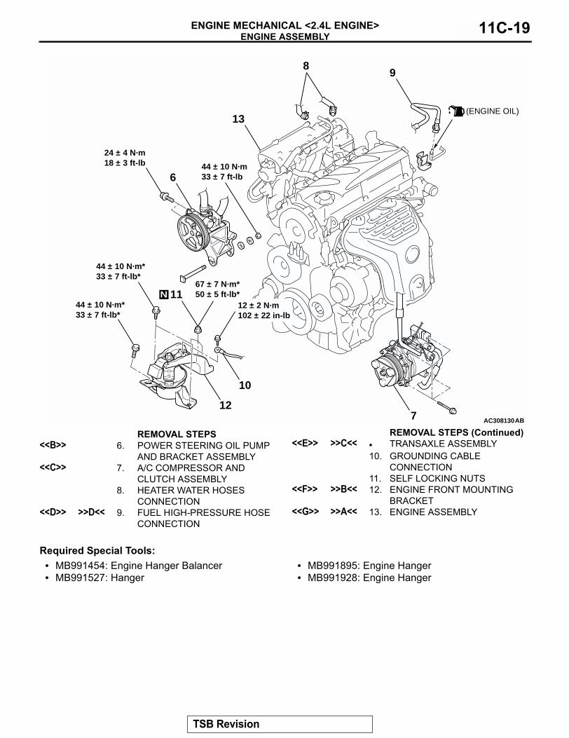
Required Special Tools:• MB991454: Engine Hanger Balancer• MB991527: Hanger
• MB991895: Engine Hanger• MB991928: Engine Hanger
AC308130AB
(ENGINE OIL)13
12
10
98
7
6
11
24 ± 4 N·m18 ± 3 ft-lb 44 ± 10 N·m
33 ± 7 ft-lb
67 ± 7 N·m*50 ± 5 ft-lb*
44 ± 10 N·m*33 ± 7 ft-lb*
44 ± 10 N·m*33 ± 7 ft-lb*
12 ± 2 N·m102 ± 22 in-lb
N
REMOVAL STEPS<<B>> 6. POWER STEERING OIL PUMP
AND BRACKET ASSEMBLY <<C>> 7. A/C COMPRESSOR AND
CLUTCH ASSEMBLY8. HEATER WATER HOSES
CONNECTION<<D>> >>D<< 9. FUEL HIGH-PRESSURE HOSE
CONNECTION
<<E>> >>C<< • TRANSAXLE ASSEMBLY10. GROUNDING CABLE
CONNECTION11. SELF LOCKING NUTS
<<F>> >>B<< 12. ENGINE FRONT MOUNTING BRACKET
<<G>> >>A<< 13. ENGINE ASSEMBLY
REMOVAL STEPS (Continued)
TSB Revision
ENGINE ASSEMBLYENGINE MECHANICAL <2.4L ENGINE>11C-20
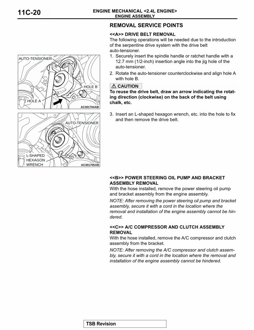
REMOVAL SERVICE POINTS.
<<A>> DRIVE BELT REMOVALThe following operations will be needed due to the introduction of the serpentine drive system with the drive belt auto-tensioner.1. Securely insert the spindle handle or ratchet handle with a
12.7 mm (1/2-inch) insertion angle into the jig hole of the auto-tensioner.
2. Rotate the auto-tensioner counterclockwise and align hole A with hole B.CAUTION
To reuse the drive belt, draw an arrow indicating the rotat-ing direction (clockwise) on the back of the belt using chalk, etc.
3. Insert an L-shaped hexagon wrench, etc. into the hole to fix and then remove the drive belt.
.
<<B>> POWER STEERING OIL PUMP AND BRACKET ASSEMBLY REMOVALWith the hose installed, remove the power steering oil pump and bracket assembly from the engine assembly.NOTE: After removing the power steering oil pump and bracket assembly, secure it with a cord in the location where the removal and installation of the engine assembly cannot be hin-dered. .
<<C>> A/C COMPRESSOR AND CLUTCH ASSEMBLY REMOVALWith the hose installed, remove the A/C compressor and clutch assembly from the bracket.NOTE: After removing the A/C compressor and clutch assem-bly, secure it with a cord in the location where the removal and installation of the engine assembly cannot be hindered. .
AC301703
AC301704AB
AUTO-TENSIONER
HOLE B
HOLE A
AC301705AB
AUTO-TENSIONER
L-SHAPEDHEXAGONWRENCH
TSB Revision
ENGINE ASSEMBLYENGINE MECHANICAL <2.4L ENGINE> 11C-21
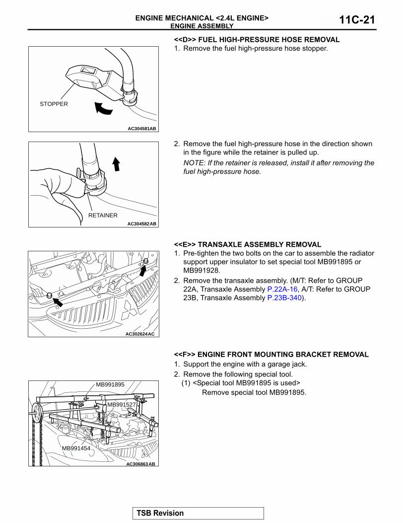
<<D>> FUEL HIGH-PRESSURE HOSE REMOVAL1. Remove the fuel high-pressure hose stopper.
2. Remove the fuel high-pressure hose in the direction shown in the figure while the retainer is pulled up. NOTE: If the retainer is released, install it after removing the fuel high-pressure hose.
.
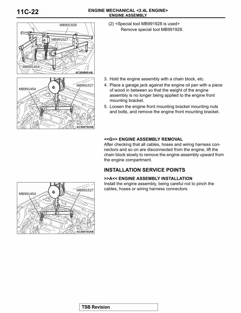
<<E>> TRANSAXLE ASSEMBLY REMOVAL1. Pre-tighten the two bolts on the car to assemble the radiator
support upper insulator to set special tool MB991895 or MB991928.
2. Remove the transaxle assembly. (M/T: Refer to GROUP 22A, Transaxle Assembly P.22A-16, A/T: Refer to GROUP 23B, Transaxle Assembly P.23B-340).
.
<<F>> ENGINE FRONT MOUNTING BRACKET REMOVAL1. Support the engine with a garage jack.2. Remove the following special tool.
(1) <Special tool MB991895 is used>Remove special tool MB991895.
AC304581AB
STOPPER
AC304582AB
RETAINER
AC302624AC
AC306863
MB991895
MB991454
AB
MB991527
TSB Revision
ENGINE ASSEMBLYENGINE MECHANICAL <2.4L ENGINE>11C-22
(2) <Special tool MB991928 is used>Remove special tool MB991928.
3. Hold the engine assembly with a chain block, etc.4. Place a garage jack against the engine oil pan with a piece
of wood in between so that the weight of the engine assembly is no longer being applied to the engine front mounting bracket.
5. Loosen the engine front mounting bracket mounting nuts and bolts, and remove the engine front mounting bracket.
.
<<G>> ENGINE ASSEMBLY REMOVALAfter checking that all cables, hoses and wiring harness con-nectors and so on are disconnected from the engine, lift the chain block slowly to remove the engine assembly upward from the engine compartment.
INSTALLATION SERVICE POINTS.
>>A<< ENGINE ASSEMBLY INSTALLATIONInstall the engine assembly, being careful not to pinch the cables, hoses or wiring harness connectors.
.
AC306865AB
MB991454
MB991928
MB991527
AC306753AB
MB991527MB991454
AC306753AB
MB991527MB991454
TSB Revision

ENGINE ASSEMBLYENGINE MECHANICAL <2.4L ENGINE> 11C-23
>>B<< ENGINE FRONT MOUNTING BRACKET INSTALLATION1. Place a garage jack against the engine oil pan with a piece
of wood in between, and install the engine front mounting bracket while adjusting the position of the engine.
2. Support the engine assembly with a garage jack.3. Remove the chain block.4. Use the following special tool as during removal to support
the engine.(1) <Special tool MB991895 is used>
Set special tool MB991895. (M/T: Refer to GROUP 22A, Transaxle Assembly P.22A-16, A/T: Refer to GROUP 23B, Transaxle Assembly P.23B-340).
(2) <Special tool MB991928 is used>Set special tool MB991928. (M/T: Refer to GROUP 22A, Transaxle Assembly P.22A-16, A/T: Refer to GROUP 23B, Transaxle Assembly P.23B-340).
.
>>C<<TRANSAXLE ASSEMBLY INSTALLATION1. Install the transaxle assembly. (M/T: Refer to GROUP 22A,
Transaxle Assembly P.22A-16, A/T: Refer to GROUP 23B, Transaxle Assembly P.23B-340).
2. Remove from the car the two bolts, to assemble the radiator support upper insulator.
.
AC306863
MB991895
MB991454
AB
MB991527
AC306865AB
MB991454
MB991928
MB991527
AC302624AC
TSB Revision

ENGINE ASSEMBLYENGINE MECHANICAL <2.4L ENGINE>11C-24
>>D<< FUEL HIGH-PRESSURE HOSE INSTALLATIONCAUTION
After connecting the fuel high-pressure hose, slightly pull it to ensure that it is installed securely. Also confirm that there is a play approximately 3 mm (0.12 inch). Then install the stopper securely.Apply a small amount of engine oil to the fuel line pipe and then install the fuel high-pressure hose.
AC301864AB
3 mm(0.12 in)
FUEL HIGH-PRESSURE HOSE
FUEL LINE PIPE(ENGINE OIL APPLIED)
AC304583ABSTOPPER
TSB Revision
CRANKSHAFT PULLEYENGINE MECHANICAL <2.4L ENGINE> 11C-25
CRANKSHAFT PULLEYREMOVAL AND INSTALLATION
M1112001600517
REMOVAL SERVICE POINTS.
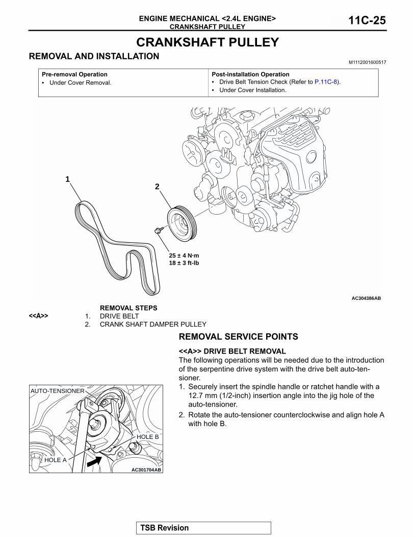
<<A>> DRIVE BELT REMOVALThe following operations will be needed due to the introduction of the serpentine drive system with the drive belt auto-ten-sioner.1. Securely insert the spindle handle or ratchet handle with a
12.7 mm (1/2-inch) insertion angle into the jig hole of the auto-tensioner.
2. Rotate the auto-tensioner counterclockwise and align hole A with hole B.
Pre-removal Operation• Under Cover Removal.
Post-installation Operation• Drive Belt Tension Check (Refer to P.11C-8).• Under Cover Installation.
AC304386
12
25 ± 4 N·m18 ± 3 ft-lb
AB
REMOVAL STEPS<<A>> 1. DRIVE BELT
2. CRANK SHAFT DAMPER PULLEY
AC301703
AC301704AB
AUTO-TENSIONER
HOLE B
HOLE A
TSB Revision
CRANKSHAFT PULLEYENGINE MECHANICAL <2.4L ENGINE>11C-26
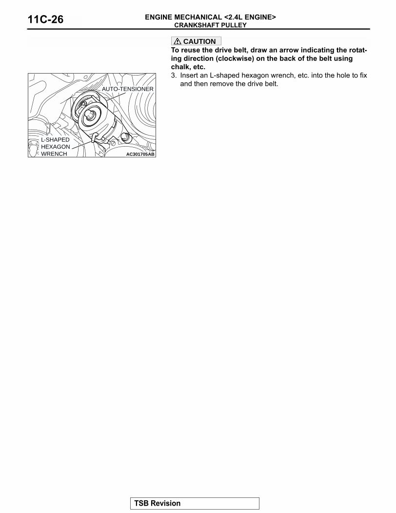
CAUTIONTo reuse the drive belt, draw an arrow indicating the rotat-ing direction (clockwise) on the back of the belt using chalk, etc.3. Insert an L-shaped hexagon wrench, etc. into the hole to fix
and then remove the drive belt.
AC301705AB
AUTO-TENSIONER
L-SHAPEDHEXAGONWRENCH
TSB Revision
CAMSHAFT AND VALVE STEM SEALENGINE MECHANICAL <2.4L ENGINE> 11C-27
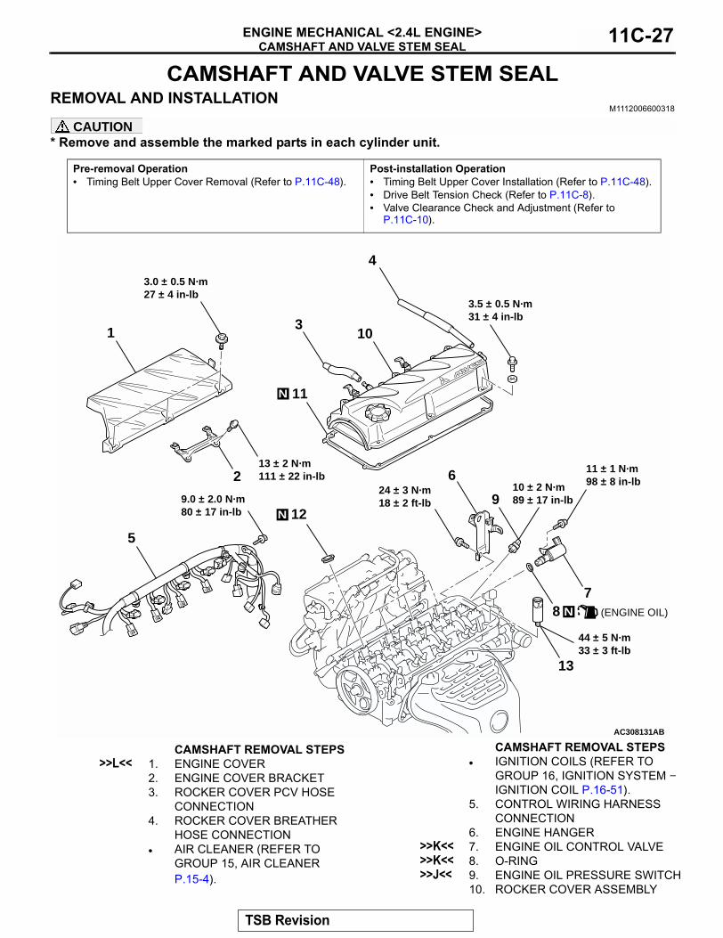
CAMSHAFT AND VALVE STEM SEALREMOVAL AND INSTALLATION
M1112006600318
CAUTION* Remove and assemble the marked parts in each cylinder unit.
Pre-removal Operation• Timing Belt Upper Cover Removal (Refer to P.11C-48).
Post-installation Operation• Timing Belt Upper Cover Installation (Refer to P.11C-48).• Drive Belt Tension Check (Refer to P.11C-8).• Valve Clearance Check and Adjustment (Refer to
P.11C-10).
AC308131
3
13
12
11
10
9
7
6
5
4
N
AB
N
11 ± 1 N·m98 ± 8 in-lb
3.5 ± 0.5 N·m31 ± 4 in-lb
24 ± 3 N·m18 ± 2 ft-lb
44 ± 5 N·m33 ± 3 ft-lb
9.0 ± 2.0 N·m80 ± 17 in-lb
(ENGINE OIL)
10 ± 2 N·m89 ± 17 in-lb
8 N
1
213 ± 2 N·m111 ± 22 in-lb
3.0 ± 0.5 N·m27 ± 4 in-lb
CAMSHAFT REMOVAL STEPS>>L<< 1. ENGINE COVER
2. ENGINE COVER BRACKET3. ROCKER COVER PCV HOSE
CONNECTION4. ROCKER COVER BREATHER
HOSE CONNECTION• AIR CLEANER (REFER TO
GROUP 15, AIR CLEANER P.15-4).
• IGNITION COILS (REFER TO GROUP 16, IGNITION SYSTEM − IGNITION COIL P.16-51).
5. CONTROL WIRING HARNESS CONNECTION
6. ENGINE HANGER>>K<< 7. ENGINE OIL CONTROL VALVE>>K<< 8. O-RING>>J<< 9. ENGINE OIL PRESSURE SWITCH
10. ROCKER COVER ASSEMBLY
CAMSHAFT REMOVAL STEPS
TSB Revision
CAMSHAFT AND VALVE STEM SEALENGINE MECHANICAL <2.4L ENGINE>11C-28
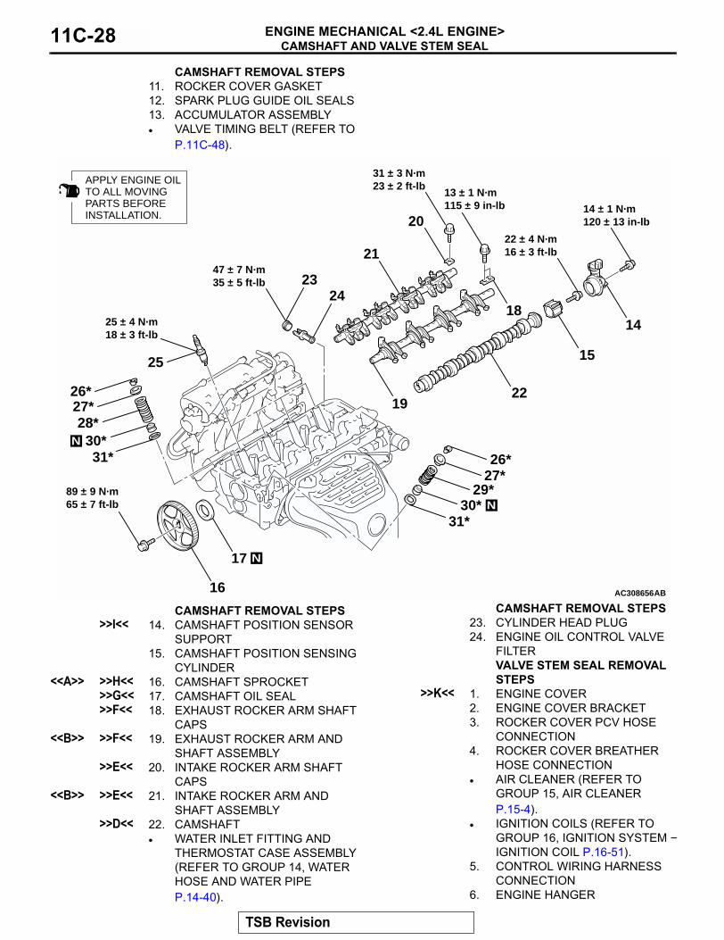
11. ROCKER COVER GASKET12. SPARK PLUG GUIDE OIL SEALS13. ACCUMULATOR ASSEMBLY• VALVE TIMING BELT (REFER TO
P.11C-48).
CAMSHAFT REMOVAL STEPS
AC308656AB
20
19
18
17
16
15
14
30*
29*
28*27*26*
25
2423
21
22
N
30*
27*26*
14 ± 1 N·m120 ± 13 in-lb
22 ± 4 N·m16 ± 3 ft-lb
13 ± 1 N·m115 ± 9 in-lb
31 ± 3 N·m23 ± 2 ft-lb
47 ± 7 N·m35 ± 5 ft-lb
25 ± 4 N·m18 ± 3 ft-lb
89 ± 9 N·m65 ± 7 ft-lb N
N
APPLY ENGINE OILTO ALL MOVINGPARTS BEFOREINSTALLATION.
31*
31*
CAMSHAFT REMOVAL STEPS>>I<< 14. CAMSHAFT POSITION SENSOR
SUPPORT15. CAMSHAFT POSITION SENSING
CYLINDER<<A>> >>H<< 16. CAMSHAFT SPROCKET
>>G<< 17. CAMSHAFT OIL SEAL>>F<< 18. EXHAUST ROCKER ARM SHAFT
CAPS<<B>> >>F<< 19. EXHAUST ROCKER ARM AND
SHAFT ASSEMBLY>>E<< 20. INTAKE ROCKER ARM SHAFT
CAPS<<B>> >>E<< 21. INTAKE ROCKER ARM AND
SHAFT ASSEMBLY>>D<< 22. CAMSHAFT
• WATER INLET FITTING AND THERMOSTAT CASE ASSEMBLY (REFER TO GROUP 14, WATER HOSE AND WATER PIPE P.14-40).
23. CYLINDER HEAD PLUG24. ENGINE OIL CONTROL VALVE
FILTERVALVE STEM SEAL REMOVAL STEPS
>>K<< 1. ENGINE COVER2. ENGINE COVER BRACKET3. ROCKER COVER PCV HOSE
CONNECTION4. ROCKER COVER BREATHER
HOSE CONNECTION• AIR CLEANER (REFER TO
GROUP 15, AIR CLEANER P.15-4).
• IGNITION COILS (REFER TO GROUP 16, IGNITION SYSTEM − IGNITION COIL P.16-51).
5. CONTROL WIRING HARNESS CONNECTION
6. ENGINE HANGER
CAMSHAFT REMOVAL STEPS
TSB Revision
CAMSHAFT AND VALVE STEM SEALENGINE MECHANICAL <2.4L ENGINE> 11C-29
Required Special Tools:• MB990767: Front Hub and Flange Yoke Holder• MD998713: Camshaft Oil Seal Installer• MD998719: Pin
• MD998772: Valve Spring Compressor• MD998774: Valve Stem Seal Installer
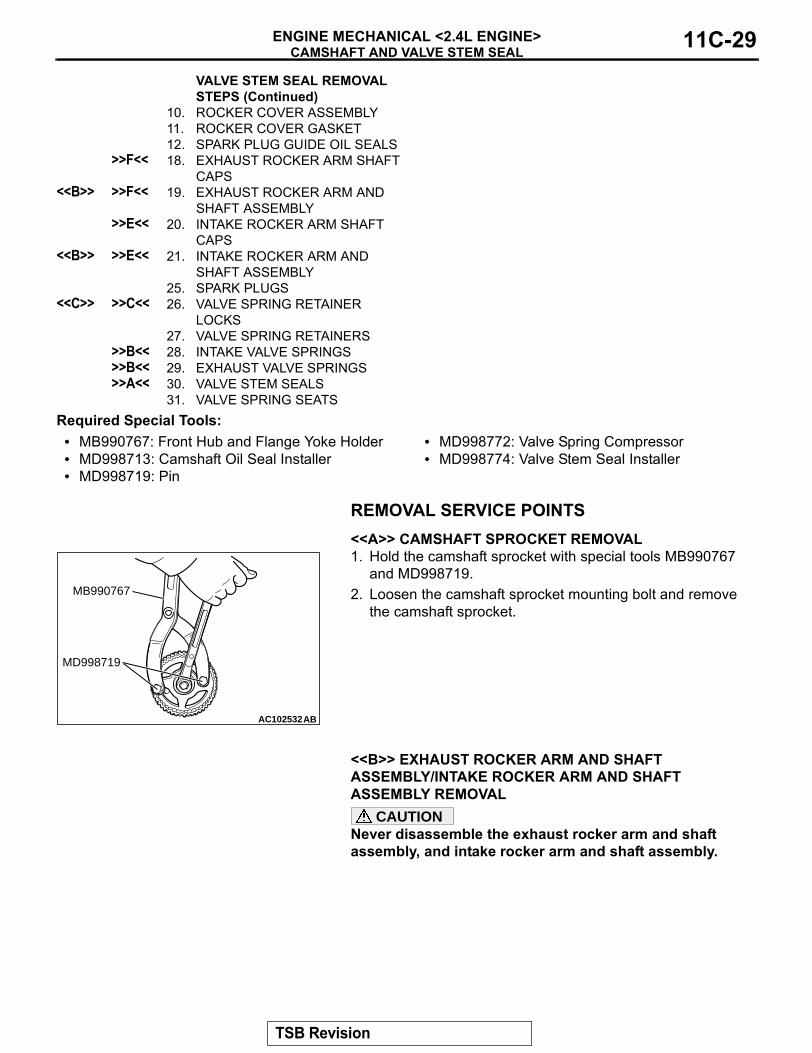
REMOVAL SERVICE POINTS.
<<A>> CAMSHAFT SPROCKET REMOVAL1. Hold the camshaft sprocket with special tools MB990767
and MD998719.2. Loosen the camshaft sprocket mounting bolt and remove
the camshaft sprocket.
.
<<B>> EXHAUST ROCKER ARM AND SHAFT ASSEMBLY/INTAKE ROCKER ARM AND SHAFT ASSEMBLY REMOVAL
CAUTIONNever disassemble the exhaust rocker arm and shaft assembly, and intake rocker arm and shaft assembly..
10. ROCKER COVER ASSEMBLY11. ROCKER COVER GASKET12. SPARK PLUG GUIDE OIL SEALS
>>F<< 18. EXHAUST ROCKER ARM SHAFT CAPS
<<B>> >>F<< 19. EXHAUST ROCKER ARM AND SHAFT ASSEMBLY
>>E<< 20. INTAKE ROCKER ARM SHAFT CAPS
<<B>> >>E<< 21. INTAKE ROCKER ARM AND SHAFT ASSEMBLY
25. SPARK PLUGS<<C>> >>C<< 26. VALVE SPRING RETAINER
LOCKS27. VALVE SPRING RETAINERS
>>B<< 28. INTAKE VALVE SPRINGS>>B<< 29. EXHAUST VALVE SPRINGS>>A<< 30. VALVE STEM SEALS
31. VALVE SPRING SEATS
VALVE STEM SEAL REMOVAL STEPS (Continued)
AC102532AB
MB990767
MD998719
TSB Revision

CAMSHAFT AND VALVE STEM SEALENGINE MECHANICAL <2.4L ENGINE>11C-30
<<C>> VALVE SPRING RETAINER LOCKS REMOVALCAUTION
When removing valve spring retainer locks, leave the pis-ton of each cylinder in the TDC (Top Dead Center) position. The valve may fall into the cylinder if the piston is not properly in the TDC position.Use special tool MD998772 to compress the valve spring and then remove the valve spring retainer locks.
INSTALLATION SERVICE POINTS.
>>A<< VALVE STEM SEALS INSTALLATION1. Apply a small amount of engine oil to the valve stem seals.
CAUTION• Do not re-use the valve stem seal.• The special tool MD998774 must be used to install the
valve stem seal. Improper installation could result in oil leaking past the valve guide.
2. Use special tool MD998774 to fill a new valve stem seal in the valve guide using the valve stem area as a guide.
.
>>B<< EXHAUST VALVE SPRINGS/INTAKE VALVE SPRINGS INSTALLATIONInstall the valve springs with its identification color painted end facing the locker arm.
.
AC301867AB
MD998772
AC308654AB
MD998774
VALVE
VALVE STEM SEAL
VALVE GUIDE
AC107415AD
ROCKER ARM SIDE
IDENTIFICATIONCOLOR INTAKE SIDE: LIGHT BLUE EXHAUST SIDE: ORANGE
TSB Revision

CAMSHAFT AND VALVE STEM SEALENGINE MECHANICAL <2.4L ENGINE> 11C-31
>>C<< VALVE SPRING RETAINER LOCKS INSTALLATIONUse special tool MD998772 to compress the valve spring and then install the valve spring retainer lock in the same manner as removal.
.
>>D<< CAMSHAFT INSTALLATIONSet the dowel pin of the camshaft in the position shown in the figure.
.
>>E<< INTAKE ROCKER ARM AND SHAFT ASSEMBLY/INTAKE ROCKER ARM SHAFT CAPS INSTALLATION1. Place the intake rocker shaft so that its 5.5 mm (0.22 inch)
hole faces toward the cylinder head.2. Install the intake rocker arm shaft caps.3. Tighten the intake rocker shaft mounting bolts to the
specified torque.Tightening torque: 31 ± 3 N⋅m (23 ± 2 ft-lb)
.
>>F<< EXHAUST ROCKER ARM AND SHAFT ASSEMBLY/EXHAUST ROCKER ARM SHAFT CAPS INSTALLATION1. Install the exhaust rocker shaft so that its notch is positioned
as shown.2. Install the exhaust rocker arm shaft caps.3. Tighten the exhaust rocker shaft mounting bolts to the
specified torque.Tightening torque: 13 ± 1 N⋅m (115 ± 9 in-lb)
AC301867AB
MD998772
AC301868AB
DOWEL PIN
AC301869
ENGINE FRONT
AB
φ 5.5 mm(0.22 in)
AC301870
ENGINE FRONT
AB
NOTCH
TSB Revision
CAMSHAFT AND VALVE STEM SEALENGINE MECHANICAL <2.4L ENGINE>11C-32
.
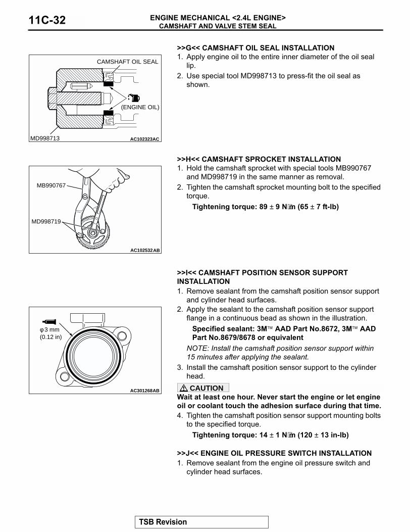
>>G<< CAMSHAFT OIL SEAL INSTALLATION1. Apply engine oil to the entire inner diameter of the oil seal
lip.2. Use special tool MD998713 to press-fit the oil seal as
shown.
.
>>H<< CAMSHAFT SPROCKET INSTALLATION1. Hold the camshaft sprocket with special tools MB990767
and MD998719 in the same manner as removal.2. Tighten the camshaft sprocket mounting bolt to the specified
torque.Tightening torque: 89 ± 9 N⋅m (65 ± 7 ft-lb)
.
>>I<< CAMSHAFT POSITION SENSOR SUPPORT INSTALLATION1. Remove sealant from the camshaft position sensor support
and cylinder head surfaces.2. Apply the sealant to the camshaft position sensor support
flange in a continuous bead as shown in the illustration.Specified sealant: 3M� AAD Part No.8672, 3M� AAD Part No.8679/8678 or equivalent
NOTE: Install the camshaft position sensor support within 15 minutes after applying the sealant.
3. Install the camshaft position sensor support to the cylinder head.CAUTION
Wait at least one hour. Never start the engine or let engine oil or coolant touch the adhesion surface during that time.4. Tighten the camshaft position sensor support mounting bolts
to the specified torque.Tightening torque: 14 ± 1 N⋅m (120 ± 13 in-lb)
.
>>J<< ENGINE OIL PRESSURE SWITCH INSTALLATION1. Remove sealant from the engine oil pressure switch and
cylinder head surfaces.
AC102323ACMD998713
CAMSHAFT OIL SEAL
(ENGINE OIL)
AC102532AB
MB990767
MD998719
AC301268AB
φ 3 mm(0.12 in)
TSB Revision

CAMSHAFT AND VALVE STEM SEALENGINE MECHANICAL <2.4L ENGINE> 11C-33
2. Apply sealant to the thread of the engine oil pressure switch as shown.
Specified sealant: 3M� AAD Part No.8672, 3M� AAD Part No.8679/8678 or equivalent
NOTE: Install the engine oil pressure switch within 15 min-utes after applying the sealant.CAUTION
Wait at least one hour. Never start the engine or let engine oil or coolant touch the adhesion surface during that time.
3. Tighten the engine oil pressure switch to the specified torque as shown.
Tightening torque: 10 ± 2 N⋅m (89 ± 17 in-lb)
.
>>K<< O-RING/ENGINE OIL CONTROL VALVE INSTALLATION
CAUTION• Never re-use the O-ring.• Before installing O-ring, wind the tape with the soft
adhesion (sealing tape) around the oil passages cut-out area of engine oil control valve to prevent the damage. If the O-ring is damaged, it can be the cause of oil leak.
1. Apply a small amount of engine oil to the O-ring and then install it to the engine oil control valve.
2. Assemble the engine oil control valve to the cylinder head.3. Tighten the engine oil control valve mounting bolt to the
specified torque.Tightening torque: 11 ± 1 N⋅m (98 ± 8 in-lb)
.
>>L<< ENGINE COVER INSTALLATION1. Engage the engine cover claws in the engine cover bracket.2. Finger-tighten the engine cover mounting bolts in the order
shown in the figure so that the engine cover can be moved by hand.
3. Tighten the engine cover mounting bolts to the specified torque in the order shown.
Tightening torque: 3.0 ± 0.5 N⋅m (27 ± 4 in-lb)
AC304807AB
1 mm(0.039 in)
5 mm(0.20 in)
AC304808AB
ENGINE OIL PRESSURESWITCH
AK303651AD
TAPE
AC302273AB
2 31
CLAWS
TSB Revision

OIL PANENGINE MECHANICAL <2.4L ENGINE>11C-34
OIL PANREMOVAL AND INSTALLATION
M1112002800741
Required Special Tool:• MD998727: Oil Pan Remover
Pre-removal Operation• Under Cover Removal.• Engine Oil Draining (Refer to GROUP 12, On-vehicle Ser-
vice − Engine Oil Replacement P.12-4).• Front Exhaust Pipe Removal (Refer to GROUP 15,
Exhaust Pipe and Main Muffler P.15-13).
Post-installation Operation• Front Exhaust Pipe Installation (Refer to GROUP 15,
Exhaust Pipe and Main Muffler P.15-13).• Engine Oil Refilling (Refer to GROUP 12, On-vehicle Ser-
vice − Engine Oil Replacement P.12-4).• Under Cover Installation.
AC304389
N
9.0 ± 3.0 N·m80 ± 26 in-lb
9.0 ± 3.0 N·m80 ± 26 in-lb 26 ± 5 N·m
19 ± 4 ft-lb
9.0 ± 1.0 N·m80 ± 9 in-lb
39 ± 5 N·m29 ± 3 ft-lb
2
3
4
1
AB
REMOVAL STEPS1. TORQUE CONVERTER HOUSING
FRONT LOWER COVER2. ENGINE OIL PAN DRAIN PLUG
>>B<< 3. ENGINE OIL PAN DRAIN PLUG GASKET
<<A>> >>A<< 4. ENGINE OIL PAN
REMOVAL STEPS (Continued)
TSB Revision

OIL PANENGINE MECHANICAL <2.4L ENGINE> 11C-35
REMOVAL SERVICE POINT.
<<A>> ENGINE OIL PAN REMOVAL1. Remove the engine oil pan mounting bolts.
CAUTIONDo not use special tool MD998727 in area A of the engine oil pan. Using the special tool in area A may cause defor-mation of the front case because the front case is made of aluminum.2. Tap special tool MD998727 into the range (B) between the
cylinder block and the engine oil pan, and then slide the tool sideways.NOTE: If any sounding parts interfere with the removal, there is no need to use special tool MD998727.
3. Remove the engine oil pan.
INSTALLATION SERVICE POINTS.
>>A<< ENGINE OIL PAN INSTALLATION1. Remove sealant from the engine oil pan, front case and
cylinder block surfaces.2. Apply a bead of the sealant to the cylinder block mating
surface of the engine oil pan as shown.Specified sealant: 3M� AAD Part No.8672, 8704, 3M� AAD Part No.8679/8678 or equivalent
NOTE: Install the engine oil pan within 15 minutes after applying sealant.
3. Assemble the engine oil pan to the cylinder block.
AC301325
A
B
AB
AC104547
MD998727 MD998727
AC
AC102133ABGROOVE
φ 4 mm(0.16 in)
PORTIONBOLT HOLEPORTION
TSB Revision
OIL PANENGINE MECHANICAL <2.4L ENGINE>11C-36
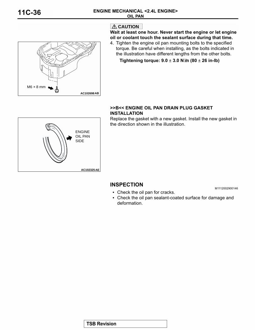
CAUTIONWait at least one hour. Never start the engine or let engine oil or coolant touch the sealant surface during that time.4. Tighten the engine oil pan mounting bolts to the specified
torque. Be careful when installing, as the bolts indicated in the illustration have different lengths from the other bolts.
Tightening torque: 9.0 ± 3.0 N⋅m (80 ± 26 in-lb)
.
>>B<< ENGINE OIL PAN DRAIN PLUG GASKET INSTALLATIONReplace the gasket with a new gasket. Install the new gasket in the direction shown in the illustration.
INSPECTIONM1112002900146
• Check the oil pan for cracks.• Check the oil pan sealant-coated surface for damage and
deformation.
AC102698
M6 × 8 mm
AB
AC102325AE
ENGINE OIL PAN SIDE
TSB Revision

CRANKSHAFT OIL SEALENGINE MECHANICAL <2.4L ENGINE> 11C-37
CRANKSHAFT OIL SEALREMOVAL AND INSTALLATION
M1112003100392
<M/T>
Required Special Tools:• MB990938: Installer Bar• MD998285: Crankshaft Front Oil Seal Guide• MD998375: Crankshaft Front Oil Seal Installer
• MD998776: Crankshaft Rear Oil Seal Installer• MD998781: Flywheel Stopper
AC3086981
2
3 N
9
8
7
6 4
N
132 ± 5 N·m98 ± 3 ft-lb
(LIP SECTION)
ENGINE OIL
AB
(LIP SECTION)
3 9
5
CRANKSHAFT FRONT OIL SEAL REMOVAL STEPS
• VALVE TIMING BELT AND BALANCER TIMING BELT (REFER TO P.11C-48).
>>D<< 1. CRANKSHAFT BALANCER SHAFT DRIVE SPROCKET
2. CRANKSHAFT KEY>>C<< 3. CRANKSHAFT FRONT OIL SEAL
CRANKSHAFT REAR OIL SEAL REMOVAL STEPS
<<A>> • TRANSAXLE ASSEMBLY<<B>> >>B<< 4. FLYWHEEL BOLTS
5. FLYWHEEL ADAPTER PLATE6. FLYWHEEL ASSEMBLY7. FLYWHEEL ADAPTER PLATE 8. CRANKSHAFT BUSH
>>A<< 9. CRANKSHAFT REAR OIL SEAL
TSB Revision

CRANKSHAFT OIL SEALENGINE MECHANICAL <2.4L ENGINE>11C-38
<A/T>
Required Special Tools:• MB990938: Installer Bar• MD998285: Crankshaft Front Oil Seal Guide• MD998375: Crankshaft Front Oil Seal Installer
• MD998776: Crankshaft Rear Oil Seal Installer• MD998781: Flywheel Stopper
AC3043911
2
3 N
8
7
6
5
4
N
132 ± 5 N·m98 ± 3 ft-lb
(LIP SECTION)
ENGINE OIL
AB
(LIP SECTION)
3 8
CRANKSHAFT FRONT OIL SEAL REMOVAL STEPS
• VALVE TIMING BELT AND BALANCER TIMING BELT (REFER TO P.11C-48).
>>D<< 1. CRANKSHAFT BALANCER SHAFT DRIVE SPROCKET
2. CRANKSHAFT KEY>>C<< 3. CRANKSHAFT FRONT OIL SEAL
CRANKSHAFT REAR OIL SEAL REMOVAL STEPS
• TRANSAXLE ASSEMBLY (REFER TO GROUP 23B, TRANSAXLE ASSEMBLY P.23B-340).
<<B>> >>B<< 4. A/T DRIVE PLATE BOLTS5. A/T DRIVE PLATE ADAPTER
PLATE6. A/T DRIVE PLATE 7. CRANKSHAFT BUSH
>>A<< 8. CRANKSHAFT REAR OIL SEAL
TSB Revision

CRANKSHAFT OIL SEALENGINE MECHANICAL <2.4L ENGINE> 11C-39
REMOVAL SERVICE POINT.
<<A>> TRANSAXLE ASSEMBLY REMOVALCAUTION
Do not remove the flywheel bolt shown by the arrow. If this bolt is removed, the flywheel assembly will become out of balance and damaged.Refer to GROUP 22A, Transaxle Assembly P.22A-16.
.
<<B>> FLYWHEEL BOLTS/A/T DRIVE PLATE BOLTS REMOVAL1. Use special tool MD998781 to secure the flywheel assembly
or A/T drive plate.2. Remove the flywheel bolts or A/T drive plate bolts.
INSTALLATION SERVICE POINTS.
>>A<< CRANKSHAFT REAR OIL SEAL INSTALLATION1. Apply a small amount of engine oil to the entire inner
diameter of the oil seal lip.2. Use special tools MB990938 and MD998776 to press-fit the
oil seal.
.
AC300897
AC308604AB
FLYWHEELBOLT
ENGINE FRONT
FLYWHEELASSEMBLY
AC301854AB
MD998781
AC102328AB
OIL SEAL
MB990938
MD998776 CRANKSHAFT
(ENGINE OIL)
TSB Revision

CRANKSHAFT OIL SEALENGINE MECHANICAL <2.4L ENGINE>11C-40
>>B<< FLYWHEEL BOLTS/A/T DRIVE PLATE BOLTS INSTALLATION1. Use special tool MD998781 to secure the flywheel assembly
or A/T drive plate in the same manner as removal.2. Tighten the flywheel bolts or A/T drive plate bolts to the
specified torque.Tightening torque: 132 ± 5 N⋅m (98 ± 3 ft-lb)
.
>>C<< CRANKSHAFT FRONT OIL SEAL INSTALLATION1. Apply a small amount of engine oil to the outer diameter of
special tool MD998285 and install it to the crankshaft.2. Apply a small amount of engine oil to the entire inner
diameter of the oil seal lip.3. Use special tool MD998375 to press-fit the oil seal.
.
>>D<< CRANKSHAFT BALANCER SHAFT DRIVE SPROCKET INSTALLATION1. Clean or degrease the front case, the crankshaft and the
crankshaft balancer shaft drive sprocket as shown.NOTE: Also clean the degreased surfaces.
2. Install the crankshaft balancer shaft drive sprocket in the direction shown in the illustration.
AC301855AB
MD998781
AC102329AC
MD998285
(ENGINE OIL)
(OIL APPLIED TO THECIRCUMFERENCE)
OIL SEAL
CRANKSHAFT MD998375
AC301346AB
: CLEAN: CLEAN AND DEGREASE
ENGINE FRONT
CRANKSHAFT BALANCERSHAFT DRIVE SPROCKET
CRANKSHAFT
FRONT CASE
TSB Revision

CYLINDER HEAD GASKETENGINE MECHANICAL <2.4L ENGINE> 11C-41
CYLINDER HEAD GASKETREMOVAL AND INSTALLATION
M1112004000837
Pre-removal Operation• Fuel Line Pressure Reduction [Refer to GROUP 13B,
On-vehicle Service − Fuel Pump Connector Disconnec-tion (How to Reduce Pressurized Fuel Lines) P.13B-906].
• Engine Coolant Draining (Refer to GROUP 14, On-vehicle Service − Engine Coolant Replacement P.14-25).
• Strut Tower Bar Removal (Refer to GROUP 42, Strut Tower Bar P.42-12).
• Engine Cover Removal (Refer to P.11C-27).• Air Cleaner Removal (Refer to GROUP 15, Air Cleaner
P.15-4).• Accelerator Cable Removal (Refer to GROUP 17, Accel-
erator Cable and Pedal P.17-7).
Post-installation Operation• Accelerator Cable Installation (Refer to GROUP 17,
Accelerator Cable and Pedal P.17-7).• Air Cleaner Installation (Refer to GROUP 15, Air Cleaner
P.15-4).• Engine Cover Installation (Refer to P.11C-27).• Strut Tower Bar Installation (Refer to GROUP 42, Strut
Tower Bar P.42-12).• Engine Coolant Refilling (Refer to GROUP 14, On-vehicle
Service − Engine Coolant Replacement P.14-25).• Accelerator Cable Adjustment (Refer to GROUP 17,
On-vehicle Service − Accelerator Cable Check and Adjustment P.17-6).
• Fuel Leak Check
AC308132
N(ENGINE OIL)
13 ± 1 N·m115 ± 9 in-lb 14 ± 3 N·m
124 ± 26 in-lb
9.0 ± 2.0 N·m80 ± 17 in-lb
5.0 ± 1.0 N·m44 ± 9 in-lb
1
6
54
3
2
AB
7
REMOVAL STEPS1. CONTROL WIRING HARNESS
CONNECTION2. BATTERY WIRING HARNESS
CONNECTION3. RADIATOR LOWER HOSE
CLAMP
4. EVAPORATIVE EMISSION VACUUM HOSE CONNECTION
5. BRAKE BOOSTER VACUUM HOSE CONNECTION
6. ENGINE OIL DIPSTICK AND DIPSTICK GUIDE
7. O-RING
REMOVAL STEPS (Continued)
TSB Revision
CYLINDER HEAD GASKETENGINE MECHANICAL <2.4L ENGINE>11C-42
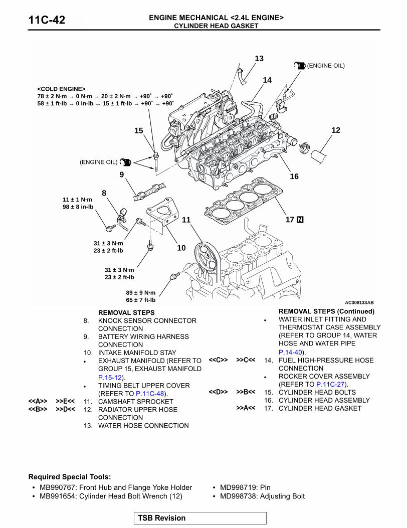
Required Special Tools:• MB990767: Front Hub and Flange Yoke Holder• MB991654: Cylinder Head Bolt Wrench (12)
• MD998719: Pin• MD998738: Adjusting Bolt
AC308133AB
<COLD ENGINE>78 ± 2 N·m → 0 N·m → 20 ± 2 N·m → +90˚ → +90˚58 ± 1 ft-lb → 0 in-lb → 15 ± 1 ft-lb → +90˚ → +90˚
17
16
15
14
13
12
10
9
8
11 N
(ENGINE OIL)
89 ± 9 N·m65 ± 7 ft-lb
11 ± 1 N·m98 ± 8 in-lb
31 ± 3 N·m23 ± 2 ft-lb
31 ± 3 N·m23 ± 2 ft-lb
(ENGINE OIL)
REMOVAL STEPS8. KNOCK SENSOR CONNECTOR
CONNECTION9. BATTERY WIRING HARNESS
CONNECTION10. INTAKE MANIFOLD STAY• EXHAUST MANIFOLD (REFER TO
GROUP 15, EXHAUST MANIFOLD P.15-12).
• TIMING BELT UPPER COVER (REFER TO P.11C-48).
<<A>> >>E<< 11. CAMSHAFT SPROCKET<<B>> >>D<< 12. RADIATOR UPPER HOSE
CONNECTION13. WATER HOSE CONNECTION
• WATER INLET FITTING AND THERMOSTAT CASE ASSEMBLY (REFER TO GROUP 14, WATER HOSE AND WATER PIPE P.14-40).
<<C>> >>C<< 14. FUEL HIGH-PRESSURE HOSE CONNECTION
• ROCKER COVER ASSEMBLY (REFER TO P.11C-27).
<<D>> >>B<< 15. CYLINDER HEAD BOLTS16. CYLINDER HEAD ASSEMBLY
>>A<< 17. CYLINDER HEAD GASKET
REMOVAL STEPS (Continued)
TSB Revision

CYLINDER HEAD GASKETENGINE MECHANICAL <2.4L ENGINE> 11C-43
REMOVAL SERVICE POINTS.
<<A>> CAMSHAFT SPROCKET REMOVALCAUTION
Never turn the crankshaft counterclockwise.1. Turn the crankshaft clockwise, align the timing marks on the
camshaft sprocket to set number 1 cylinder to TDC of its compression stroke.
2. Remove the timing belt under cover rubber plug and then set special tool MD998738.
3. Screw in special tool MD998738 until it contacts the timing belt tensioner arm.
4. Secure the camshaft sprocket and valve timing belt with wiring bands and so on to prevent slippage between the camshaft sprocket and valve timing belt.
AC301450AB
TIMING MARK
AC301452AB
MD998738
TIMING BELTUNDER COVER
AC301373AB
TIMING BELT TENSIONER ARM
MD998738
AC107621
AC301451AC
WIRING BAND
TSB Revision

CYLINDER HEAD GASKETENGINE MECHANICAL <2.4L ENGINE>11C-44
5. Hold the camshaft sprocket with special tools MB990767 and MD998719.CAUTION
Do not rotate the crankshaft after camshaft sprocket removal.6. Remove the camshaft sprocket with the valve timing belt
and place it on the timing belt lower cover.
.
<<B>> RADIATOR UPPER HOSE DISCONNECTIONMake mating marks on the radiator upper hose and the hose clamp. Disconnect the radiator upper hose.
.
<<C>> FUEL HIGH-PRESSURE HOSE REMOVAL1. Remove the fuel high-pressure hose stopper.
2. Remove the fuel high-pressure hose in the direction shown in the figure while the retainer is pulled up. NOTE: If the retainer is released, install it after removing the fuel high-pressure hose.
.
AC100302
MD998719
MB990767
AB
AC200641AB
MATING MARKS
AC304581AB
STOPPER
AC304582AB
RETAINER
TSB Revision

CYLINDER HEAD GASKETENGINE MECHANICAL <2.4L ENGINE> 11C-45
<<D>> CYLINDER HEAD BOLTS REMOVALUse special tool MB991654 to loosen the cylinder head bolts in two or three steps in the order of the numbers shown in the illustration. If the cylinder head bolts cannot be pulled out due to the washer being trapped in the valve spring, raise the bolt slightly, then remove it while holding it by using a magnet.
INSTALLATION SERVICE POINTS.
>>A<< CYLINDER HEAD GASKET INSTALLATIONCAUTION
Do not allow any foreign materials get into the coolant pas-sages, oil passages and cylinder.1. Degrease the cylinder head gasket mounting surface.2. Assemble to the cylinder block so the cylinder head gasket
identification mark of "381" is at the top surface and on the exhaust side.
.
>>B<< CYLINDER HEAD BOLTS INSTALLATION1. Check that the nominal length of each cylinder head bolt
meets the limit. If it exceeds the limit, replace the bolts with a new one.
Limit (A): 99.4 mm (3.91 inches)2. Apply a small amount of engine oil to the thread of the bolts
and to the washers.
AC301454AB
ENGINE FRONT
MB991654
105 283
97 461
AC302180AB
IDENTIFICATION MARK "381"
EXHAUST SIDE
AC102537
A
AC
(ENGINE OIL)
TSB Revision

CYLINDER HEAD GASKETENGINE MECHANICAL <2.4L ENGINE>11C-46
3. Use special tool MB991654 to tighten the cylinder head bolts in the following procedures.(1) Tighten the bolts to 78 ± 2 N⋅m (58 ± 1 ft-lb) in the order
shown.(2) Loosen the bolts fully in the reverse sequence to that
shown.(3) Tighten the bolts to 20 ± 2 N⋅m (15 ± 1 ft-lb) in the order
shown.
(4) Apply a paint mark to the heads of the cylinder head bolts and cylinder head, then tighten 90 degree angle as shown.
CAUTION• The bolt is not tightening sufficiently if the tightening
angle is less than a 90 degree angle.• If the tightening angle exceeds the standard specifica-
tion, remove the bolt and start over from step 1.(5) Tighten in a 90 degree angle as shown in the instructions
of the figure, then check to see that the paint mark on the head of the cylinder head bolts and the paint mark on the cylinder head is on a linear line.
.
AC301456AB
ENGINE FRONT
MB991654
10
9
7524
8 6 1 3
AC102331AB
PAINT MARKING
90˚ 90˚
PAINT MARKING
STEP (4) STEP (5)
TSB Revision

CYLINDER HEAD GASKETENGINE MECHANICAL <2.4L ENGINE> 11C-47
>>C<< FUEL HIGH-PRESSURE HOSE INSTALLATIONCAUTION
After connecting the fuel high-pressure hose, slightly pull it to ensure that it is installed securely. Also confirm that there is a play approximately 3 mm (0.12 inch). Then install the stopper securely.Apply a small amount of engine oil to the fuel line pipe and then install the fuel high-pressure hose.
.
>>D<< RADIATOR UPPER HOSE CONNECTION1. Insert radiator upper hose until it contacts the projection on
the water outlet fitting.2. Align the mating marks on the radiator upper hose and hose
clamp, and then secure the radiator upper hose.
.
>>E<< CAMSHAFT SPROCKET INSTALLATION1. Hold the camshaft sprocket with special tools MB990767
and MD998719 in the same manner as removal.2. Tighten the camshaft sprocket mounting bolt to the specified
torque.Tightening torque: 89 ± 9 N⋅m (65 ± 7 ft-lb)
AC301864AB
3 mm(0.12 in)
FUEL HIGH-PRESSURE HOSE
FUEL LINE PIPE(ENGINE OIL APPLIED)
AC304583ABSTOPPER
AC200642
MATINGMARKS
PROJECTION
WATER OUTLETFITTING
AB
AC102532AB
MB990767
MD998719
TSB Revision

TIMING BELTENGINE MECHANICAL <2.4L ENGINE>11C-48
TIMING BELTREMOVAL AND INSTALLATION
M1112004300805
Pre-removal Operation• Under Cover Removal.• Crankshaft Shaft Damper Pulley Removal (Refer to
P.11C-25).
Post-installation Operation• Crankshaft Shaft Damper Pulley Installation (Refer to
P.11C-25).• Drive Belt Tension Check (Refer to P.11C-8).• Under Cover Installation.
AC304394AB
14 ± 1 N·m120 ± 13 in-lb
1
13
12
10
9
8
7
6
5
11
43
2
14 ± 1 N·m120 ± 13 in-lb
8.8 ± 1.0 N·m78 ± 9 in-lb
44 ± 10 N·m33 ± 7 ft-lb
22 ± 4 N·m16 ± 3 ft-lb
11 ± 1 N·m98 ± 8 in-lb 9.0 ± 1.0 N·m
80 ± 9 in-lb
11 ± 1 N·m98 ± 8 in-lb
79 ± 5 N·m59 ± 3 ft-lb
11 ± 1 N·m98 ± 8 in-lb
21 ± 4 N·m16 ± 2 ft-lb
48 ± 5 N·m36 ± 3 ft-lb
23 ± 3 N·m17 ± 2 ft-lb
14 ± 3 N·m124 ± 26 in-lb
REMOVAL STEPS1. CONTROL WIRING HARNESS
CONNECTION2. BATTERY WIRING HARNESS
CONNECTION3. CONNECTOR BRACKET• ENGINE FRONT MOUNTING
BRACKET (REFER TO GROUP 32, ENGINE MOUNT P.32-4).
4. HARNESS BRACKET5. TIMING BELT UPPER COVER 6. WATER PUMP PULLEY
7. IDLER PULLEY8. AUTO-TENSIONER9. TIMING BELT LOWER COVER
>>G<< • VALVE TIMING BELT TENSION ADJUSTMENT (INSTALLATION ONLY)
<<A>> >>F<< 10. VALVE TIMING BELT >>E<< 11. TIMING BELT TENSIONER
PULLEY12. TIMING BELT TENSIONER ARM
>>D<< 13. TIMING BELT TENSIONER ADJUSTER
REMOVAL STEPS (Continued)
TSB Revision

TIMING BELTENGINE MECHANICAL <2.4L ENGINE> 11C-49
Required Special Tools:• MB991367: Special Spanner • MB991385: Pin
• MD998738: Adjusting Bolt• MD998767: Tensioner Wrench
AC304395
19
18
17
1615
14
22
20
21
(ENGINE OIL)
35 ± 6 N·m26 ± 4 ft-lb
8.5 ± 0.5 N·m76 ± 4 in-lb
19 ± 3 N·m14 ± 2 ft-lb
167 N·m123 ft-lb
AB
REMOVAL STEPS14. TIMING BELT IDLER PULLEY15. TIMING BELT LOWER COVER
BRACKET16. CRANKSHAFT POSITION
SENSOR <<B>> >>C<< 17. CRANKSHAFT PULLEY CENTER
BOLT<<B>> >>C<< 18. CRANKSHAFT PULLEY WASHER<<B>> >>C<< 19. CRANKSHAFT CAMSHAFT
DRIVE SPROCKET
>>C<< 20. CRANKSHAFT ANGLE SENSING BLADE
>>B<< • BALANCER TIMING BELT TENSION ADJUSTMENT (INSTALLATION ONLY)
>>A<< 21. BALANCER TIMING BELT TENSIONER
<<C>> >>A<< 22. BALANCER TIMING BELT
REMOVAL STEPS (Continued)
TSB Revision

TIMING BELTENGINE MECHANICAL <2.4L ENGINE>11C-50
REMOVAL SERVICE POINTS.
<<A>> VALVE TIMING BELT REMOVALCAUTION
Never turn the crankshaft counterclockwise.1. Turn the crankshaft clockwise, align each timing mark to set
number 1 cylinder to TDC of its compression stroke.
2. Remove the timing belt under cover rubber plug and then set special tool MD998738.
3. Screw in special tool MD998738 with hands until it contacts the timing belt tensioner arm.
AC301866AB
TIMING MARK
CAMSHAFT SPROCKET
CRANKSHAFT CAMSHAFTDRIVE SPROCKET
ENGINE OIL PUMP SPROCKET
TIMING MARK
TIMING MARK
AC301452AB
MD998738
TIMING BELTUNDER COVER
AC301373AB
TIMING BELT TENSIONER ARM
MD998738
TSB Revision
TIMING BELTENGINE MECHANICAL <2.4L ENGINE> 11C-51
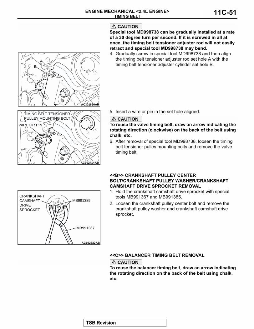
CAUTIONSpecial tool MD998738 can be gradually installed at a rate of a 30 degree turn per second. If it is screwed in all at once, the timing belt tensioner adjuster rod will not easily retract and special tool MD998738 may bend.4. Gradually screw in special tool MD998738 and then align
the timing belt tensioner adjuster rod set hole A with the timing belt tensioner adjuster cylinder set hole B.
5. Insert a wire or pin in the set hole aligned.CAUTION
To reuse the valve timing belt, draw an arrow indicating the rotating direction (clockwise) on the back of the belt using chalk, etc.6. After removal of special tool MD998738, loosen the timing
belt tensioner pulley mounting bolts and remove the valve timing belt.
.
<<B>> CRANKSHAFT PULLEY CENTER BOLT/CRANKSHAFT PULLEY WASHER/CRANKSHAFT CAMSHAFT DRIVE SPROCKET REMOVAL1. Hold the crankshaft camshaft drive sprocket with special
tools MB991367 and MB991385.2. Loosen the crankshaft pulley center bolt and remove the
crankshaft pulley washer and crankshaft camshaft drive sprocket.
.
<<C>> BALANCER TIMING BELT REMOVALCAUTION
To reuse the balancer timing belt, draw an arrow indicating the rotating direction on the back of the belt using chalk, etc.
AC301856
A
B
AB
AC302414AB
WIRE OR PIN
TIMING BELT TENSIONER PULLEY MOUNTING BOLT
AC102332AB
MB991385
MB991367
CRANKSHAFTCAMSHAFTDRIVE SPROCKET
TSB Revision
TIMING BELTENGINE MECHANICAL <2.4L ENGINE>11C-52
INSTALLATION SERVICE POINTS.
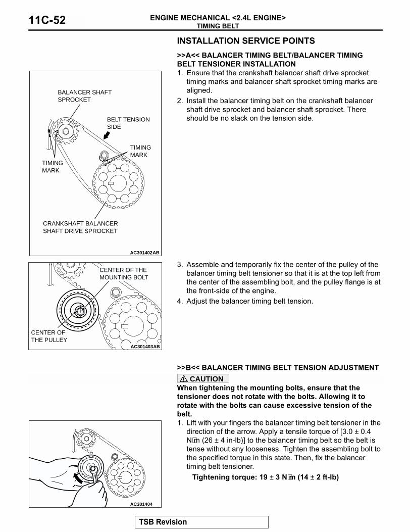
>>A<< BALANCER TIMING BELT/BALANCER TIMING BELT TENSIONER INSTALLATION1. Ensure that the crankshaft balancer shaft drive sprocket
timing marks and balancer shaft sprocket timing marks are aligned.
2. Install the balancer timing belt on the crankshaft balancer shaft drive sprocket and balancer shaft sprocket. There should be no slack on the tension side.
3. Assemble and temporarily fix the center of the pulley of the balancer timing belt tensioner so that it is at the top left from the center of the assembling bolt, and the pulley flange is at the front-side of the engine.
4. Adjust the balancer timing belt tension.
.
>>B<< BALANCER TIMING BELT TENSION ADJUSTMENTCAUTION
When tightening the mounting bolts, ensure that the tensioner does not rotate with the bolts. Allowing it to rotate with the bolts can cause excessive tension of the belt.1. Lift with your fingers the balancer timing belt tensioner in the
direction of the arrow. Apply a tensile torque of [3.0 ± 0.4 N⋅m (26 ± 4 in-lb)] to the balancer timing belt so the belt is tense without any looseness. Tighten the assembling bolt to the specified torque in this state. Then, fix the balancer timing belt tensioner.
Tightening torque: 19 ± 3 N⋅m (14 ± 2 ft-lb)
AC301402AB
TIMING MARK
TIMING MARK
CRANKSHAFT BALANCER SHAFT DRIVE SPROCKET
BALANCER SHAFTSPROCKET
BELT TENSION SIDE
AC301403AB
CENTER OF THE PULLEY
CENTER OF THE MOUNTING BOLT
AC301404
TSB Revision

TIMING BELTENGINE MECHANICAL <2.4L ENGINE> 11C-53
2. Turn the crankshaft clockwise two turns to set number 1 cylinder to TDC of its compression stroke and check that sprocket timing marks are aligned.
3. Apply a pressure of approximately 100 N (22 pounds) at the center (arrow area) between the sprocket as shown in the figure, then inspect whether the belt deflection is within the standard value.
Standard value:<When adjusting> 5 − 7 mm (0.20 − 0.27 inch)<When replacing> 5 − 7 mm (0.20 − 0.27 inch)
4. If not within the standard value, adjust the belt tension again.
.
AC301402AC
TIMING MARK
TIMING MARK
CRANKSHAFT BALANCER SHAFT DRIVE SPROCKET
BALANCER SHAFTSPROCKET
AC301405AB
APPROXIMATELY100 N (22 lb)
DEFLECTION
TSB Revision
TIMING BELTENGINE MECHANICAL <2.4L ENGINE>11C-54
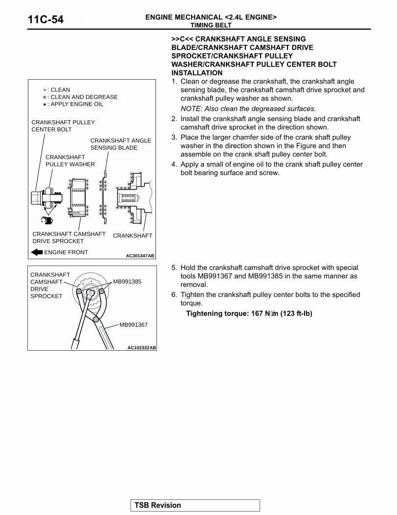
>>C<< CRANKSHAFT ANGLE SENSING BLADE/CRANKSHAFT CAMSHAFT DRIVE SPROCKET/CRANKSHAFT PULLEY WASHER/CRANKSHAFT PULLEY CENTER BOLT INSTALLATION1. Clean or degrease the crankshaft, the crankshaft angle
sensing blade, the crankshaft camshaft drive sprocket and crankshaft pulley washer as shown.NOTE: Also clean the degreased surfaces.
2. Install the crankshaft angle sensing blade and crankshaft camshaft drive sprocket in the direction shown.
3. Place the larger chamfer side of the crank shaft pulley washer in the direction shown in the Figure and then assemble on the crank shaft pulley center bolt.
4. Apply a small of engine oil to the crank shaft pulley center bolt bearing surface and screw.
5. Hold the crankshaft camshaft drive sprocket with special tools MB991367 and MB991385 in the same manner as removal.
6. Tighten the crankshaft pulley center bolts to the specified torque.
Tightening torque: 167 N⋅m (123 ft-lb)
.
AC301347ABENGINE FRONT
CRANKSHAFT CAMSHAFTDRIVE SPROCKET
CRANKSHAFT PULLEY CENTER BOLT
CRANKSHAFT PULLEY WASHER
CRANKSHAFT ANGLESENSING BLADE
CRANKSHAFT
: CLEAN
: APPLY ENGINE OIL: CLEAN AND DEGREASE
AC102332AB
MB991385
MB991367
CRANKSHAFTCAMSHAFTDRIVE SPROCKET
TSB Revision

TIMING BELTENGINE MECHANICAL <2.4L ENGINE> 11C-55
>>D<< TIMING BELT TENSIONER ADJUSTER INSTALLATION1. Set according to the following procedures when the timing
belt tensioner adjuster rod is fully extended.CAUTION
If the compression is too fast the procedure may damage the rod. Make a point to slowly and thoroughly compress.
(1) Slowly compress the timing belt tensioner adjuster rod using a press or vice, then align the set hole A of the rod with set hole B of the timing belt tensioner adjuster cylinder.
(2) Insert a wire or pin in the set hole aligned.NOTE: When replacing the timing belt tensioner adjuster with new parts, the timing belt tensioner adjuster is set with a pin.
2. Install the timing belt tensioner adjuster to the engine and then tighten the mounting bolt to the specified torque. Do not remove the wire or pin until the tension of the valve timing belt is adjusted.
Tightening torque: 23 ± 3 N⋅m (17 ± 2 ft-lb).
>>E<< TIMING BELT TENSIONER PULLEY INSTALLATIONTemporarily tighten the timing belt tensioner pulley as shown.
.
AC302024
A
AB
B
AC302025
WIRE OR PIN
AB
AC102336AB
TIMING BELT TENSIONERPULLEY HOLE
TSB Revision

TIMING BELTENGINE MECHANICAL <2.4L ENGINE>11C-56
>>F<< VALVE TIMING BELT INSTALLATION1. Align the timing marks on the camshaft sprocket, crankshaft
camshaft drive sprocket and engine oil pump sprocket.
2. Adjust the timing mark of the engine oil pump sprocket. Unplug the cylinder block plug. Insert a bolt (M6, section width 10 mm, nominal length 45 mm) from the plug hole. If the bolt comes in contact with the balancer shaft, turn the engine oil sprocket one rotation. Re-adjust the timing mark and then check to see that the bolt fits. Do not remove the bolt until the valve timing belt is assembled.
AC301374AB
TIMING MARK
TIMING MARK
TIMING MARK
CAMSHAFT SPROCKET
CRANKSHAFT CAMSHAFT DRIVE SPROCKET
ENGINE OIL PUMP SPROCKET
AC200795AB
BOLT
BALANCERSHAFT
CYLINDERBLOCK
PLUG
TSB Revision
TIMING BELTENGINE MECHANICAL <2.4L ENGINE> 11C-57
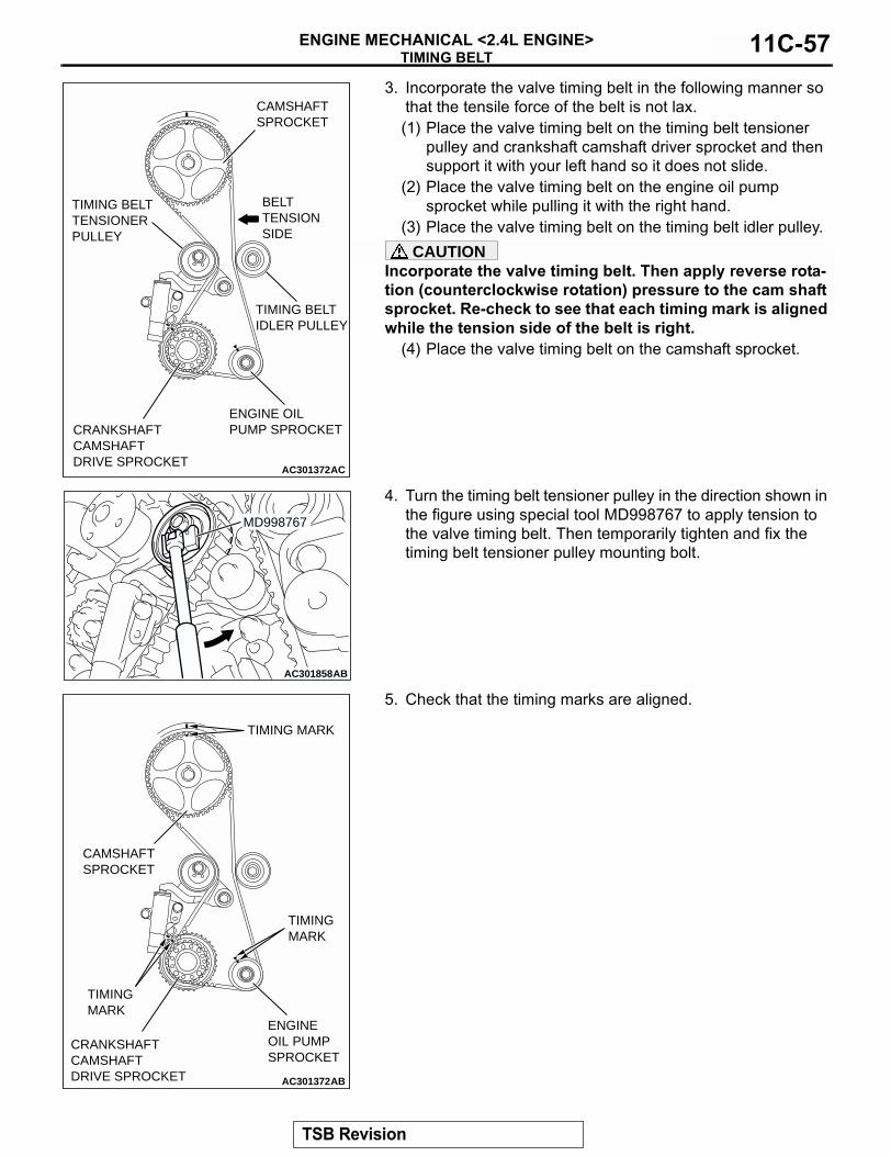
3. Incorporate the valve timing belt in the following manner so that the tensile force of the belt is not lax. (1) Place the valve timing belt on the timing belt tensioner
pulley and crankshaft camshaft driver sprocket and then support it with your left hand so it does not slide.
(2) Place the valve timing belt on the engine oil pump sprocket while pulling it with the right hand.
(3) Place the valve timing belt on the timing belt idler pulley.CAUTION
Incorporate the valve timing belt. Then apply reverse rota-tion (counterclockwise rotation) pressure to the cam shaft sprocket. Re-check to see that each timing mark is aligned while the tension side of the belt is right.
(4) Place the valve timing belt on the camshaft sprocket.
4. Turn the timing belt tensioner pulley in the direction shown in the figure using special tool MD998767 to apply tension to the valve timing belt. Then temporarily tighten and fix the timing belt tensioner pulley mounting bolt.
5. Check that the timing marks are aligned.
AC301372AC
TIMING BELT TENSIONER PULLEY
CAMSHAFT SPROCKET
CRANKSHAFTCAMSHAFT DRIVE SPROCKET
ENGINE OILPUMP SPROCKET
BELTTENSION SIDE
TIMING BELT IDLER PULLEY
AC301858
MD998767
AB
AC301372AB
TIMING MARK
TIMING MARK
TIMING MARK
CAMSHAFT SPROCKET
CRANKSHAFT CAMSHAFTDRIVE SPROCKET
ENGINE OIL PUMP SPROCKET
TSB Revision

TIMING BELTENGINE MECHANICAL <2.4L ENGINE>11C-58
6. Remove the bolt inserted in Step 2 above, then assemble the cylinder block plug.
7. Tighten the cylinder block plug to the specified torque.Tightening torque: 30 ± 3 N⋅m (23 ± 2 ft-lb)
8. Adjust the valve timing belt tension.
.
>>G<< VALVE TIMING BELT TENSION ADJUSTMENT 1. Set special tool MD998738 used when removing the valve
timing belt.CAUTION
Always screw in special tool MD998738 in with your hands, since use of a spanner or other tools may damage the wire or pin inserted in the timing belt tensioner adjuster. 2. Gradually screw in special tool MD998738 to a position in
which the wire or pin inserted in the timing belt tensioner adjuster lightly moves.
3. Turn the crankshaft 1/4 of a revolution in the counterclockwise direction.
4. Turn the crankshaft in the clockwise direction, align each timing mark to set number 1 cylinder to TDC of its compression stroke.
5. Loosen the timing belt tensioner pulley mounting bolt.
AC200795AB
BOLT
BALANCERSHAFT
CYLINDERBLOCK
PLUG
AC301452AB
MD998738
TIMING BELTUNDER COVER
AC301372AB
TIMING MARK
TIMING MARK
TIMING MARK
CAMSHAFT SPROCKET
CRANKSHAFT CAMSHAFTDRIVE SPROCKET
ENGINE OIL PUMP SPROCKET
TSB Revision

TIMING BELTENGINE MECHANICAL <2.4L ENGINE> 11C-59
CAUTIONWhen tightening the mounting bolt, ensure that the timing belt tensioner pulley does not rotate with the bolt. Allowing it to rotate with the bolt can cause deficient tension of the belt.6. With special tool MD998767 and torque wrench, apply
tension torque [3.5 N⋅m (31 in-lb)] to the valve timing belt, and tighten the timing belt tensioner pulley mounting bolt to the specified torque.
Tightening torque: 48 ± 5 N⋅m (36 ± 3 ft-lb)
7. Remove wire or pin inserted to timing belt tensioner adjuster.
8. Remove special tool MD998738, and install the rubber plug to the timing belt under cover.
9. Rotate crankshaft clockwise two turns, and leave it for about 15 minutes.
10.Insert wire or pin removed in Step 7 again, and ensure that it can be pulled out with a light load. When wire or pin can be lightly removed, appropriate tension is applied on timing belt. In this case, remove wire or pin.
AC301859
MD998767
AB
AC301857AB
WIRE OR PIN
AC301452AB
MD998738
TIMING BELTUNDER COVER
AC301857AB
WIRE OR PIN
TSB Revision

TIMING BELTENGINE MECHANICAL <2.4L ENGINE>11C-60
Also the projection of timing belt tensioner adjuster rod (A) is within the standard value, appropriate tension is applied.
Standard value (A): 3.8 − 4.5 mm (0.15 − 0.17 inch)11.If wire or pin cannot be easily pulled out, repeat Step 1
through Step 9 to reach proper valve timing belt tension.CAUTION
Always check the tightening torque of the crank shaft pul-ley center bolt when turning the crank shaft pulley center bolt counterclockwise. Re-tighten if it is loose.
12.Check again that the timing marks on sprockets are aligned.
INSPECTIONM1112004400459
TIMING BELT TENSIONER ADJUSTER CHECK1. Check for oil leak from seal, and replace it if leak is detected.2. Check for wear or damage at the top of the rod. Replace it, if
required.3. Hold the timing belt tensioner adjuster by hand, and press
top end of the rod onto the metal (e.g. cylinder block) under a pressure of 98 − 196 N (22 − 44 pounds) to measure the movement of the rod.
Standard value: Within 1 mm (0.039 inch)A: Length when it is free (not pressed)B: Length when it is pressedA − B: Movement
4. If the measured value is out of the standard value, replace the timing belt tensioner adjuster.
AC301375AB
ROD
A
AC301866AB
TIMING MARK
CAMSHAFT SPROCKET
CRANKSHAFT CAMSHAFTDRIVE SPROCKET
ENGINE OIL PUMP SPROCKET
TIMING MARK
TIMING MARK
AC301376AB
MOVEMENTA B
ROD
98 – 196 N (22 – 44 lb)
TSB Revision

TIMING BELTENGINE MECHANICAL <2.4L ENGINE> 11C-61
BALANCER TIMING BELT TENSION CHECK Check the balancer timing belt tension in the following proce-dures.1. Apply a pressure of approximately 100 N (22 pounds) at the
center (arrow area) between the sprocket as shown in the figure, then inspect whether the flexure is within the standard value.
Standard value: 5 − 10 mm (0.20 − 0.39 inch)2. If not within the standard value, adjust the belt tension.
(Refer to P.11C-48).
AC301405AB
APPROXIMATELY100 N (22 lb)
DEFLECTION
TSB Revision

SPECIFICATIONSENGINE MECHANICAL <2.4L ENGINE>11C-62
SPECIFICATIONSFASTENER TIGHTENING SPECIFICATIONS
M1111003800406
ITEM SPECIFICATIONCamshaft and valve stem sealAccumulator assembly 44 ± 5 N⋅m (33 ± 3 ft-lb)Camshaft position sensing cylinder bolt 22 ± 4 N⋅m (16 ± 3 ft-lb)Camshaft position sensor support bolt 14 ± 1 N⋅m (120 ± 13 in-lb)Camshaft sprocket bolt 89 ± 9 N⋅m (65 ± 7 ft-lb)Control wiring harness bolt 9.0 ± 2.0 N⋅m (80 ± 17 in-lb)Cylinder head plug 47 ± 7 N⋅m (35 ± 5 ft-lb)Engine cover bolt 3.0 ± 0.5 N⋅m (27 ± 4 in-lb)Engine cover bracket bolt 13 ± 2 N⋅m (111 ± 22 in-lb)Engine hanger bolt 24 ± 3 N⋅m (18 ± 2 ft-lb)Engine oil control valve bolt 11 ± 1 N⋅m (98 ± 8 in-lb)Engine oil pressure switch 10 ± 2 N⋅m (89 ± 17 in-lb)Exhaust rocker arm shaft bolt 13 ± 1 N⋅m (115 ± 9 in-lb)Intake rocker arm shaft bolt 31 ± 3 N⋅m (23 ± 2 ft-lb)Rocker cover assembly bolt 3.5 ± 0.5 N⋅m (31 ± 4 in-lb)Spark plug 25 ± 4 N⋅m (18 ± 3 ft-lb)Crankshaft oil sealA/T drive plate bolt <A/T> 132 ± 5 N⋅m (98 ± 3 ft-lb)Flywheel bolt <M/T> 132 ± 5 N⋅m (98 ± 3 ft-lb)Crankshaft pulleyCrankshaft damper pulley bolt 25 ± 4 N⋅m (18 ± 3 ft-lb)Cylinder head gasketBattery wiring harness nut 14 ± 3 N⋅m (124 ± 26 in-lb)Camshaft sprocket bolt 89 ± 9 N⋅m (65 ± 7 ft-lb)Control wiring harness bolt 9.0 ± 2.0 N⋅m (80 ± 17 in-lb)Cylinder head bolt <Cold engine> 78 ± 2 N⋅m → 0 N⋅m → 20 ± 2 N⋅m →
+90° → +90° (58 ± 1 ft-lb → 0 in-lb → 15 ± 1 ft-lb → +90° → +90°)
Engine oil dipstick guide bolt 13 ± 1 N⋅m (115 ± 9 in-lb)Intake manifold stay bolt 31 ± 3 N⋅m (23 ± 2 ft-lb)Knock sensor connector bracket bolt 11 ± 1 N⋅m (98 ± 8 in-lb)Radiator lower hose clamp bolt 5.0 ± 1.0 N⋅m (44 ± 9 in-lb)Engine assemblyBattery terminal nut M6 5.0 ± 1.0 N⋅m (44 ± 9 in-lb)
M8 12 ± 2 N⋅m (102 ± 22 in-lb)Battery wiring harness bolt 9.0 ± 2.0 N⋅m (80 ± 17 in-lb)Control wiring harness bolt 9.0 ± 2.0 N⋅m (80 ± 17 in-lb)Engine front mounting bracket bolt 44 ± 10 N⋅m (33 ± 7 ft-lb)
TSB Revision

SPECIFICATIONSENGINE MECHANICAL <2.4L ENGINE> 11C-63
SERVICE SPECIFICATIONSM1111000300628
Engine front mounting bracket nut 67 ± 7 N⋅m (50 ± 5 ft-lb)Grounding cable bolt 12 ± 2 N⋅m (102 ± 22 in-lb)Power steering oil pump bracket bolt 24 ± 4 N⋅m (18 ± 3 ft-lb)Power steering oil pump bracket nut 44 ± 10 N⋅m (33 ± 7 ft-lb)Oil panEngine oil pan bolt 9.0 ± 3.0 N⋅m (80 ± 26 in-lb)Engine oil pan drain plug 39 ± 5 N⋅m (29 ± 3 ft-lb)Torque converter housing front lower cover bolt (bolt, flange) M10 26 ± 5 N⋅m (19 ± 4 ft-lb)Torque converter housing front lower cover bolt (bolt, washer assembled)
M6 9.0 ± 1.0 N⋅m (80 ± 9 in-lb)
Timing beltAuto-tensioner bolt (bolt, washer assembled) M8 22 ± 4 N⋅m (16 ± 3 ft-lb)
M10 44 ± 10 N⋅m (33 ± 7 ft-lb)Balancer timing belt tensioner bolt 19 ± 3 N⋅m (14 ± 2 ft-lb)Battery wiring harness nut 14 ± 3 N⋅m (124 ± 26 in-lb)Connector bracket bolt 11 ± 1 N⋅m (98 ± 8 in-lb)Crankshaft pulley center bolt 167 N⋅m (123 ft-lb)Cylinder block plug 30 ± 3 N⋅m (23 ± 2 ft-lb)Idler pulley bolt 79 ± 5 N⋅m (59 ± 3 ft-lb)Timing belt idler pulley bolt 35 ± 6 N⋅m (26 ± 4 ft-lb)Timing belt lower cover bolt (bolt, flange) M6 11 ± 1 N⋅m (98 ± 8 in-lb)Timing belt lower cover bolt (bolt, washer assembled) M6 9.0 ± 1.0 N⋅m (80 ± 9 in-lb)Timing belt lower cover bracket bolt 8.5 ± 0.5 N⋅m (76 ± 4 in-lb)Timing belt lower cover nut 11 ± 1 N⋅m (98 ± 8 in-lb)Timing belt tensioner adjuster bolt 23 ± 3 N⋅m (17 ± 2 ft-lb)Timing belt tensioner arm bolt 21 ± 4 N⋅m (16 ± 2 ft-lb)Timing belt tensioner pulley bolt 48 ± 5 N⋅m (36 ± 3 ft-lb)Timing belt upper cover bolt (bolt, flange) M6 11 ± 1 N⋅m (98 ± 8 in-lb)
M8 14 ± 1 N⋅m (120 ± 13 in-lb)Water pump pulley bolt 8.8 ± 1.0 N⋅m (78 ± 9 in-lb)
ITEM SPECIFICATION
ITEM STANDARD VALUE LIMITDrive belt tension Vibration frequency Hz
(Reference)120 − 154 −
Tension N (Reference) 340 − 560 −Valve clearance (hot) mm (in) Intake valve 0.20 (0.008) −
Exhaust valve 0.30 (0.012) −Actual ignition timing at idle Approximately 10°
BTDC−
Basic ignition timing at idle 5°BTDC ± 3° −
TSB Revision

SPECIFICATIONSENGINE MECHANICAL <2.4L ENGINE>11C-64
SEALANTSM1111000500398
CO content% 0.5 or less −HC contents ppm 100 or less −Curb idle speed r/min 750 ± 100 −Compression pressure (200 r/min) kPa (psi) 1,560 (226) Minimum 1,130 (164)Intake manifold vacuum at curb idle kPa (in Hg) − Minimum 60 (18)Cylinder head bolt nominal length mm (in) − 99.4 (3.91)Balancer timing belt tension (When adjusted)
Deflection mm (in) 5 − 7 (0.20 − 0.27) −
Balancer timing belt tension (When replaced)
Deflection mm (in) 5 − 7 (0.20 − 0.27) −
Balancer timing belt tension (When checked)
Deflection mm (in) 5 − 10 (0.20 − 0.39) −
Timing belt tensioner adjuster rod protrusion amount mm (in) 3.8 − 4.5 (0.15 − 0.17) −Timing belt tensioner adjuster rod movement mm (in) Within 1 (0.039) −
ITEM STANDARD VALUE LIMIT
ITEM SPECIFIED SEALANTCamshaft position sensor support 3M� AAD Part No.8672, 3M� AAD Part No.8679/8678 or
equivalentEngine oil pressure switchEngine oil pan 3M� AAD Part No.8672, 8704, 3M� AAD Part No.8679/8678 or
equivalent
TSB Revision