group 16 engine electrical - lil evo 8 usa/xevo8us/evo8us/gr00002200-16.pdfgroup 16 engine...
TRANSCRIPT

16-1
GROUP 16
ENGINE ELECTRICAL
CONTENTS
CHARGING SYSTEM . . . . . . . . 16-2
GENERAL DESCRIPTION . . . . . . 16-2
SPECIAL TOOL. . . . . . . . . . . . . . . 16-3
CHARGING SYSTEM DIAGNOSIS 16-4
ON-VEHICLE SERVICE. . . . . . . . . 16-7GENERATOR OUTPUT LINE VOLTAGE DROP TEST . . . . . . . . . . . . . . . . . . . . . 16-7OUTPUT CURRENT TEST . . . . . . . . . . 16-8REGULATED VOLTAGE TEST. . . . . . . 16-10WAVE PATTERN CHECK USING AN OSCILLOSCOPE. . . . . . . . . . . . . . . . . . 16-11
GENERATOR ASSEMBLY . . . . . . 16-14REMOVAL AND INSTALLATION . . . . . 16-14DISASSEMBLY AND ASSEMBLY. . . . . 16-16INSPECTION . . . . . . . . . . . . . . . . . . . . . 16-18
STARTING SYSTEM . . . . . . . . . 16-21
GENERAL DESCRIPTION . . . . . . 16-21
DIAGNOSIS . . . . . . . . . . . . . . . . . . 16-22
ON-VEHICLE SERVICE. . . . . . . . . 16-23STARTER RELAY CHECK . . . . . . . . . . 16-23
STARTER MOTOR ASSEMBLY . . 16-24REMOVAL AND INSTALLATION . . . . . 16-24INSPECTION . . . . . . . . . . . . . . . . . . . . . 16-24DISASSEMBLY AND ASSEMBLY. . . . . 16-27INSPECTION . . . . . . . . . . . . . . . . . . . . . 16-29
IGNITION SYSTEM . . . . . . . . . 16-32
GENERAL DESCRIPTION . . . . . . . 16-32
SPECIAL TOOL . . . . . . . . . . . . . . . 16-33
ON-VEHICLE SERVICE . . . . . . . . . 16-33IGNITION COIL CHECK . . . . . . . . . . . . 16-33SPARK PLUG CABLE RESISTANCE CHECK . . . . . . . . . . . . . . . . . . . . . . . . . . 16-34SPARK PLUG CHECK AND CLEANING . . . . . . . . . . . . . . . . . . . . . . 16-35CAMSHAFT POSITION SENSOR CHECK 16-35CRANK ANGLE SENSOR CHECK . . . . 16-35IGNITION SECONDARY VOLTAGE WAVE PATTERN CHECK USING AN OSCILLOSCOPE . . . . . . . . . . . . . . . . . . 16-35
IGNITION COIL. . . . . . . . . . . . . . . . 16-39REMOVAL AND INSTALLATION. . . . . . 16-39
CAMSHAFT POSITION SENSOR . 16-39REMOVAL AND INSTALLATION. . . . . . 16-39
CRANKSHAFT POSITION SENSOR 16-40REMOVAL AND INSTALLATION. . . . . . 16-40
KNOCK SENSOR. . . . . . . . . . . . . . 16-41REMOVAL AND INSTALLATION. . . . . . 16-41
SPECIFICATIONS . . . . . . . . . . 16-42
FASTENER TIGHTENING SPECIFICATIONS . . . . . . . . . . . . . 16-42
GENERAL SPECIFICATIONS . . . . 16-43
SERVICE SPECIFICATIONS . . . . . 16-43

CHARGING SYSTEMENGINE ELECTRICAL16-2
CHARGING SYSTEMGENERAL DESCRIPTION
M1161000100254The charging system charges the battery with output from the generator to keep the battery charged at a constant level during varying electrical loads.Operation
Rotation of the excited field coil generates AC volt-age in the stator.This alternating current is rectified through diodes to DC voltage having a waveform shown in the illustra-tion above.The average output voltage fluctuates slightly with the generator load condition.
When the ignition switch is turned to the "ON" posi-tion, current flows in the field coil and initial excitation of the field coil occurs.When the stator coil begins to generate power after the engine is started, the field coil is excited by the output current of the stator coil.Generator output voltage rises as the field current increases and falls as the field current decreases. When the battery positive voltage (generator S termi-nal voltage) reaches a regulated voltage of approxi-mately 14.4 V, the field current is cut off. When the battery positive voltage drops below the regulated voltage, the voltage regulator regulates the output voltage to a constant level by controlling the field cur-rent.In addition, when the field current is constant, the generator output voltage rises as the engine speed increases.
AKX00183
VOLTAGE
TIME
APPROXIMATELY14.4 V
AB
AK100054
GENERATOR
B
STATOR COIL
ECM
G
SL
FR
VOLTAGE REGULATOR CHARGING WARNING LIGHT
IGNITION SWITCH BATTERY
FIELD COIL
+
–
AE
TSB Revision

CHARGING SYSTEMENGINE ELECTRICAL 16-3
SPECIAL TOOLM1161000600204
TOOL TOOL NUMBER AND NAME
SUPERSESSION APPLICATION
MB991502Scan tool (MUT-II)
MB991496-OD Checking of engine idle speed
MB991958A: MB991824B: MB991827C: MB991910D: MB991911E: MB991914F: MB991825G: MB991826MUT-III sub assemblyA: Vehicle Communication Interface (V.C.I.)B: MUT-III USB CableC: MUT-III Main Harness A (Vehicles with CAN communication system)D: MUT-III Main Harness B (Vehicles without CAN communication system)E: MUT-III Main Harness C (for Chrysler models only)F: MUT-III Adapter HarnessG: MUT-III Trigger Harness
Checking of engine idle speed
B991502
MB991910
MB991826
MB991958
MB991911
MB991914
MB991824
MB991827
MB991825
A
B
C
D
E
F
G
TSB Revision

CHARGING SYSTEMENGINE ELECTRICAL16-4
CHARGING SYSTEM DIAGNOSISM1161000700193
TROUBLESHOOTING HINTS1. Charging warning light does not come on when the ignition
switch is turned to "ON" position, before the engine starts.• Check the bulb.
2. Charging warning light does not switch off after the engine starts.
• Check the IC voltage regulator inside the generator.3. Discharged or overcharged battery.• Check the IC voltage regulator inside the generator.
4. The charging warning light illuminates dimly.• Check the diode (inside the combination meter or genera-
tor) for a short-circuit.
TROUBLESHOOTING GUIDEThe charging system troubleshooting guide is shown in the fol-lowing chart.
STEP 1.Q: Is the battery in good condition? (Refer to GROUP 54A,
Battery − On-vehicle Service − Battery Check P.54A-3.)YES : Go to Step 2.NO : Charge or replace the battery.
STEP 2.Q: Is the generator drive belt in good condition? (Refer to
GROUP 00, Maintenance Service − Drive Belts P.00-37.)YES : Go to Step 3.NO : Adjust the belt tension or replace the belt.
MB991519Generator harness connector
Tool not available Checking of generator (S terminal voltage)
TOOL TOOL NUMBER AND NAME
SUPERSESSION APPLICATION
TSB Revision

CHARGING SYSTEMENGINE ELECTRICAL 16-5
STEP 3.Q: Does the charging system warning light turn on brightly
when the ignition switch is turned to the "ON" position?YES : Go to Step 4.NO : • Check the ignition switch. (Refer to GROUP 54A,
Ignition switch − Inspection P.54A-53.)• Check for burnt-out charging system warning light
bulb.• Check the generator. (Refer to Generator −
Disassembly and assembly − Inspection P.16-18.)• Check the charging system warning light-related
circuits.
STEP 4.Q: Does the charging warning light go out after starting the
engine?YES : Go to Step 5.NO : Check the generator (Refer to Generator −
Disassembly and assembly − Inspection P.16-18.)
STEP 5.Q: Is an oscilloscope available?
YES : Go to Step 6.NO : Go to Step 7.
STEP 6.Q: Does the oscilloscope show a normal wave pattern?
(Refer to Charging system − Wave pattern check using a oscilloscope P.16-11.) YES : Go to Step 7.NO : Check the generator. (Refer to Generator −
Disassembly and assembly − Inspection P.16-18.)
STEP 7.• Engine: 2,500 r/min• Headlight: ON (high beam)• Voltage between generator "B" terminal and the positive
battery terminalOK: 0.5 V or less
• Voltage between the negative battery terminal and genera-tor bodyOK: 0.5 V or less
Q: Are the generator output line and ground line in good condition?YES : Go to Step 8.NO : • Check the generator output line.
• Check the generator ground line.
TSB Revision

CHARGING SYSTEMENGINE ELECTRICAL16-6
STEP 8.Q: Is the output current normal? (Refer to Charging system
− On vehicle service − Output current test P.16-8.)YES : Go to Step 9.NO : Check the generator (Refer to Generator −
Disassembly and assembly − Inspection P.16-18.)
STEP 9.Q: Is the regulated voltage normal? (Refer to Charging
system − On vehicle service − Regulated voltage test P.16-10.)YES : Go to Step 10.NO : Check the generator (Refer to Generator −
Disassembly and assembly − Inspection P.16-18.)
STEP 10.Q: Is the voltage drops in the generator output line
normal? (Refer to Charging system − On vehicle servise − Generator output line voltage drop test P.16-7.)YES : Generator is normal. Check other systems.NO : Check the output line.
TSB Revision

CHARGING SYSTEMENGINE ELECTRICAL 16-7
ON-VEHICLE SERVICEGENERATOR OUTPUT LINE VOLTAGE DROP TEST
M1161000900227
Required Special Tools:• MB991502: Scan Tool (MUT-II)• MB991958: Scan Tool (MUT-III Sub Assembly)
• MB991824: V.C.I.• MB991827: USB Cable• MB991911: Main Harness B
This test determines whether the wiring from the generator "B" terminal to the positive battery terminal (including the fusible link) is in good condition or not:
WARNINGBattery posts, terminals and related acces-sories contain lead and lead compounds. WASH HANDS AFTER HANDLING.1. Always be sure to check the following before the
test.• Generator installation• Generator drive belt tension (Refer to GROUP
00, Maintenance Service − Drive Belts P.00-37.)• Fusible link• Abnormal noise from the generator while the
engine is running.2. Turn the ignition switch to the "LOCK" (OFF)
position.3. Disconnect the negative battery cable.4. Connect a clamp-type DC test ammeter with a
range of 0 − 100 A to the generator "B" terminal output wire.
NOTE: The way of disconnecting the generator output wire and of connecting the ammeter is pos-sibly not found the problem that the output current is dropping due to the insufficient connection between terminal "B" and the output wire.
5. Connect a digital-type voltmeter between the generator "B" terminal and the positive battery terminal. (Connect the positive lead of the voltmeter to the "B" terminal, and then connect the negative lead of the voltmeter to the positive battery cable.)
6. Reconnect the negative battery cable.7. Connect an engine tachometer, scan tool
MB991502 or MB991958.8. Leave the hood open.9. Start the engine.10.With the engine running at 2,500 r/min, turn the
headlights and other lights on and off to adjust the generator load so that the value displayed on the ammeter is slightly above 30 A.Read the voltmeter. Voltage reading at or below limit value means voltage drop between generator and battery is OK.
Limit value: maximum 0.3 V NOTE: When the generator output is high and the value displayed on the ammeter does not decrease to 30 A, set the value to 40 A. Read the value displayed on the voltmeter at this time.
AK203361AC
GENERATORAMMETER(CLAMP-TYPE)
VOLTMETER(DIGITAL-TYPE)
"B" TERMINALBATTERY
TSB Revision

CHARGING SYSTEMENGINE ELECTRICAL16-8
In this case the limit value becomes maximum 0.4 V.Adjust the engine speed by gradually decreasing it until the value displayed on the ammeter is 30 A. Take a reading of the value displayed on the voltmeter at this time.
11.If the value displayed on the voltmeter is above the limit value, there is probably a malfunction in the generator output wire. Check the wiring between the generator "B" terminal and the positive battery terminal (including fusible link).
If a terminal is not sufficiently tight or if the harness has become discolored due to overheating, repair and then test again.
12.After the test, run the engine at idle. 13.Turn off all lights and turn the ignition switch to the
"LOCK" (OFF) position.14.Disconnect the engine tachometer, scan tool
MB991502 or MB991958.15.Disconnect the negative battery cable.16.Disconnect the ammeter and voltmeter.17.Connect the negative battery cable.18.Run the engine for 10 minutes at an idle.
OUTPUT CURRENT TESTM1161001000216
Required Special Tools:• MB991502: Scan Tool (MUT-II)• MB991958: Scan Tool (MUT-III Sub Assembly)
• MB991824: V.C.I.• MB991827: USB Cable• MB991911: Main Harness B
This test determines whether the generator outputs normal current. For best results, use a charging sys-tem tester. If not available, follow the steps below.
WARNINGBattery posts, terminals and related acces-sories contain lead and lead compounds. WASH HANDS AFTER HANDLING.1. Before the test, always be sure to check the
following.• Generator installation• Battery (Refer to GROUP 54A, Battery − On-
vehicle Service − Battery Check P.54A-3.)
AK203362
GENERATOR
AMMETER(CLAMP-TYPE)VOLTMETER
BATTERY
IGNITIONSWITCH
ECM
LOAD
BFR
LSG
+
AF
–
CHARGINGINDICATOR
BRAKE WARNING LIGHT
TSB Revision

CHARGING SYSTEMENGINE ELECTRICAL 16-9
NOTE: The battery to be used should be slightly discharged. The load in a fully-charged battery will be insufficient and the test may not be able to be carried out correctly.
• Generator drive belt tension (Refer to GROUP 00, Maintenance Service − Drive Belts P.00-37.)
• Fusible link• Abnormal noise from the generator while the
engine is running.2. Turn the ignition switch to the "LOCK" (OFF)
position.3. Disconnect the negative battery cable.
WARNINGNever use clips to connect the line. Loose connections (for example, using clips) will lead to a serious accident because of high current.4. Connect a clamp-type DC test ammeter with a
range of 0 − 100 A to the generator "B" terminal output wire.
5. Connect a voltmeter with a range of 0 − 20 V between the generator "B" terminal and ground. (Connect the positive lead of the voltmeter to the "B" terminal, and then connect the negative lead of the voltmeter to ground.)
6. Connect the negative battery cable.7. Connect an engine tachometer, scan tool
MB991502 or MB991958.8. Leave the hood open.9. Check to be sure that the reading on the voltmeter
is equal to the battery positive voltage.NOTE: If the voltage is 0 V, the cause is probably an open circuit in the wire or fusible link between the generator "B" terminal and the battery positive terminal or malfunctioning voltmeter.
10.After turning on the headlights, start the engine.NOTE: Because the current from the battery will soon drop after the engine is started, step 11 should be carried out as quickly as possible in order to obtain the maximum current output value.
11.Immediately after setting the headlights to high beam and turning the heater blower switch to the highest position, increase the engine speed to 2,500 r/min and read the maximum current output value displayed on the ammeter.
Limit value: 70 % of nominal current outputNOTE: For the nominal current output, refer to the Generator Specifications.NOTE: The current output value will depend on the electrical load and the temperature of the gen-erator body.NOTE: If the electrical load is small while testing, the specified level of current may not be output even though the generator is normal. In such cases, increase the electrical load by leaving the headlights turned on for some time to discharge the battery or by using the lighting system in another vehicle, and then test again.NOTE: The specified level of current also may not be output if the temperature of the generator body or the ambient temperature is too high. In such cases, cool the generator and then test again.
12.The reading on the ammeter should be above the limit value. If the reading is below the limit value and the generator output wire is normal, remove the generator from the engine and check the generator.
13.Run the engine at idle speed after the test.14.Turn the ignition switch to the "LOCK" (OFF)
position.15.Disconnect the engine tachometer, scan tool
MB991502 or MB991958.16.Disconnect the negative battery cable.17.Disconnect the ammeter and voltmeter .18.Connect the negative battery cable.19.Run the engine for 10 minutes at an idle.
TSB Revision
CHARGING SYSTEMENGINE ELECTRICAL16-10
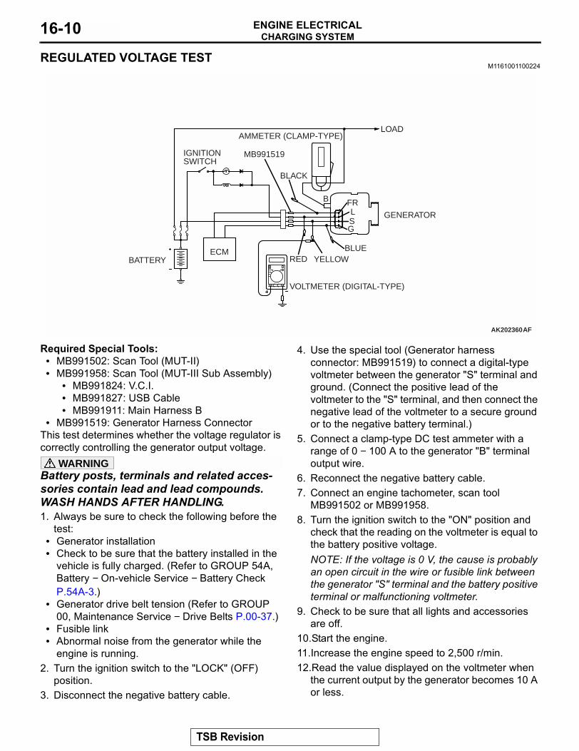
REGULATED VOLTAGE TESTM1161001100224
Required Special Tools:• MB991502: Scan Tool (MUT-II)• MB991958: Scan Tool (MUT-III Sub Assembly)
• MB991824: V.C.I.• MB991827: USB Cable• MB991911: Main Harness B
• MB991519: Generator Harness ConnectorThis test determines whether the voltage regulator is correctly controlling the generator output voltage.
WARNINGBattery posts, terminals and related acces-sories contain lead and lead compounds. WASH HANDS AFTER HANDLING.1. Always be sure to check the following before the
test:• Generator installation• Check to be sure that the battery installed in the
vehicle is fully charged. (Refer to GROUP 54A, Battery − On-vehicle Service − Battery Check P.54A-3.)
• Generator drive belt tension (Refer to GROUP 00, Maintenance Service − Drive Belts P.00-37.)
• Fusible link• Abnormal noise from the generator while the
engine is running.2. Turn the ignition switch to the "LOCK" (OFF)
position.3. Disconnect the negative battery cable.
4. Use the special tool (Generator harness connector: MB991519) to connect a digital-type voltmeter between the generator "S" terminal and ground. (Connect the positive lead of the voltmeter to the "S" terminal, and then connect the negative lead of the voltmeter to a secure ground or to the negative battery terminal.)
5. Connect a clamp-type DC test ammeter with a range of 0 − 100 A to the generator "B" terminal output wire.
6. Reconnect the negative battery cable.7. Connect an engine tachometer, scan tool
MB991502 or MB991958.8. Turn the ignition switch to the "ON" position and
check that the reading on the voltmeter is equal to the battery positive voltage.NOTE: If the voltage is 0 V, the cause is probably an open circuit in the wire or fusible link between the generator "S" terminal and the battery positive terminal or malfunctioning voltmeter.
9. Check to be sure that all lights and accessories are off.
10.Start the engine.11.Increase the engine speed to 2,500 r/min.12.Read the value displayed on the voltmeter when
the current output by the generator becomes 10 A or less.
AK202360AF
BATTERY
IGNITIONSWITCH
ECM
AMMETER (CLAMP-TYPE)LOAD
BLACK
MB991519
VOLTMETER (DIGITAL-TYPE)
RED YELLOWBLUE
GENERATOR
B FRLSG
TSB Revision

CHARGING SYSTEMENGINE ELECTRICAL 16-11
13.If the voltage reading conforms to the value in the voltage regulation table, then the voltage regulator is operating normally.If the voltage is outside the standard value, there is a malfunction of the voltage regulator or the generator (Refer to the following table).
14.After the test, lower the engine speed to idle.
15.Turn the ignition switch to the "LOCK" (OFF) position.
16.Disconnect the engine tachometer, scan tool MB991502 or MB991958.
17.Disconnect the negative battery cable.18.Disconnect the ammeter and voltmeter.19.Connect the negative battery cable.20.Run the engine for 10 minutes at an idle.
VOLTAGE REGULATION TABLE
WAVE PATTERN CHECK USING AN OSCILLOSCOPE
M1161001200094
Measurement MethodConnect the oscilloscope probe to the generator "B" terminal.
INSPECTION TERMINAL VOLTAGE REGULATOR AMBIENT TEMPERATURE [°C (°F)]
STANDARD VALUE (V)
Terminal "S" −20 (−4) 14.2 − 15.420 (68) 13.9 − 14.960 (140) 13.4 − 14.580 (176) 13.1 − 14.2
AKX00188
GENERATOROSCILLOSCOPE
"B" TERMINAL
PROBE
AB
TSB Revision

CHARGING SYSTEMENGINE ELECTRICAL16-12
Standard WaveformNOTE: The voltage waveform of the generator "B" terminal can undulate as shown at left. This waveform is produced when the regulator operates according to fluctuations in the generator load (current), and is normal for the generator. If the ripple height is abnormally high (approximately 2 V or more during idling), the wires between the generator B terminal and the bat-tery have broken due to fuse blowing, etc. The generator is usually operating properly.
Abnormal Waveforms ExamplesNOTE: The size of the waveform patterns can differ greatly, depending on the adjustment of the variable knob on the oscilloscope.NOTE: Identification of abnormal waveforms is easier when there is a large output current (regulator is not operating). (Waveforms can be observed when the headlights are illuminated.)NOTE: Check the conditions of the charging system warning light (illuminated/not illuminated) also, and carry out a total check.
OBSERVATION CONDITIONSFUNCTION SPECIAL PATTERNSPattern height Variable
Variable knob Adjust while viewing the wave pattern
Pattern selector Raster
Engine revolutions Curb idle speed
AKX00189
0.4
(V)
0.2
0
–0.2
–0.4
"NORMAL"VOLTAGE ATGENERATOR"B" TERMINAL
TIME
AD
AKX00190
TSB Revision

CHARGING SYSTEMENGINE ELECTRICAL 16-13
ABNORMAL WAVEFORMS PROBABLE CAUSEExample 1 Open circuit in diode
Example 2 Short-circuit in diode
Example 3 Open circuit in stator coil
Example 4 Short-circuit in stator coil
Example 5 Open circuit in supplementary diode
AKX00191
AKX00192
AKX00193
AKX00194
AKX00195
TSB Revision

CHARGING SYSTEMENGINE ELECTRICAL16-14
GENERATOR ASSEMBLYREMOVAL AND INSTALLATION
M1161001400429
CAUTIONIf the vehicle is equipped with the Brembo disc brake, during maintenance, take care not to contact the parts or tools to the caliper because the paint of caliper will be scratched.
Pre-removal Operation• Under Cover Removal (Refer to GROUP 51, Front
Bumper P.51-2).• Strut Tower Bar Removal (Refer to GROUP 42, Strut
Tower Bar P.42-12).• Crossmember Bar Removal (Refer to GROUP 32, Engine
Roll Stopper and Centermember P.32-6).• Front Exhaust Pipe Assembly Removal (Refer to GROUP
15, Exhaust Pipe and Main Muffler P.15-23).
Post-installation Operation• Front Exhaust Pipe Assembly Installation (Refer to
GROUP 15, Exhaust Pipe and Main Muffler P.15-23).• Crossmember Bar Installation (Refer to GROUP 32,
Engine Roll Stopper and Centermember P.32-6).• Strut Tower Bar Installation (Refer to GROUP 42, Strut
Tower Bar P.42-12).• Drive Belt Tension Adjustment [Refer to GROUP 00,
Maintenance Service − Drive Belts (Check Condition) P.00-37].
• Under Cover Installation (Refer to GROUP 51, Front Bumper P.51-2).
AC210295AB
13
2
13 ± 1 N·m115 ± 9 in-lb
8.8 ± 1.0 N·m78 ± 9 in-lb
22 ± 4 N·m16 ± 3 ft-lb
23 ± 3 N·m17 ± 2 ft-lb
36 ± 6 N·m27 ± 4 ft-lb
20 ± 2 N·m15 ± 1 ft-lb(ENGINE OIL)
1
3
4
5
6
7
9.0 ± 1.0 N·m80 ± 9 in-lb
8
11 ± 1 N·m98 ± 8 in-lb
10
95.0 ± 1.0 N·m44 ± 9 in-lb
11
12N
14
14 ± 3 N·m124 ± 26 in-lb
15
44 ± 10 N·m33 ± 7 ft-lb
16
17
18
19
N
TSB Revision
CHARGING SYSTEMENGINE ELECTRICAL 16-15
REMOVAL SERVICE POINTS.
<<A>> FUEL INJECTOR, FUEL RAIL, FUEL RETURN PIPE AND FUEL PRESSURE REGULATOR ASSEMBLY REMOVALAfter loosening the fuel rail mounting bolts, move the fuel injec-tor, fuel rail, fuel return pipe and the fuel pressure regulator as an assembly aside in order to make room for the generator removal..
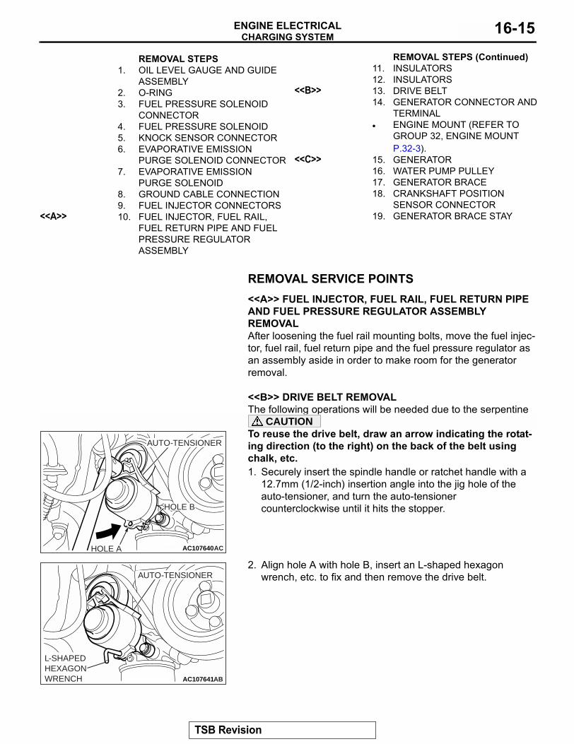
<<B>> DRIVE BELT REMOVALThe following operations will be needed due to the serpentine drive system with the drive belt auto-tensioner.CAUTIONTo reuse the drive belt, draw an arrow indicating the rotat-ing direction (to the right) on the back of the belt using chalk, etc.1. Securely insert the spindle handle or ratchet handle with a
12.7mm (1/2-inch) insertion angle into the jig hole of the auto-tensioner, and turn the auto-tensioner counterclockwise until it hits the stopper.
2. Align hole A with hole B, insert an L-shaped hexagon wrench, etc. to fix and then remove the drive belt.
.
REMOVAL STEPS1. OIL LEVEL GAUGE AND GUIDE
ASSEMBLY2. O-RING3. FUEL PRESSURE SOLENOID
CONNECTOR4. FUEL PRESSURE SOLENOID5. KNOCK SENSOR CONNECTOR6. EVAPORATIVE EMISSION
PURGE SOLENOID CONNECTOR7. EVAPORATIVE EMISSION
PURGE SOLENOID8. GROUND CABLE CONNECTION9. FUEL INJECTOR CONNECTORS
<<A>> 10. FUEL INJECTOR, FUEL RAIL, FUEL RETURN PIPE AND FUEL PRESSURE REGULATOR ASSEMBLY
11. INSULATORS12. INSULATORS
<<B>> 13. DRIVE BELT14. GENERATOR CONNECTOR AND
TERMINAL• ENGINE MOUNT (REFER TO
GROUP 32, ENGINE MOUNT P.32-3).
<<C>> 15. GENERATOR16. WATER PUMP PULLEY17. GENERATOR BRACE18. CRANKSHAFT POSITION
SENSOR CONNECTOR19. GENERATOR BRACE STAY
REMOVAL STEPS (Continued)
AC107640ACHOLE A
AUTO-TENSIONER
HOLE B
AC107641AB
L-SHAPEDHEXAGONWRENCH
AUTO-TENSIONER
TSB Revision

CHARGING SYSTEMENGINE ELECTRICAL16-16
<<C>> GENERATOR REMOVALPush up the engine with a floor jack to the top and remove the generator upward from engine room.
DISASSEMBLY AND ASSEMBLYM1161001600144
AK202845
1
2
3 4
5
67
8
9
10
11
12
13
14
AC
DISASSEMBLY STEPS<<A>> 1. FRONT BRACKET ASSEMBLY<<B>> 2. ALTERNATOR PULLEY
>>B<< 3. ROTOR4. REAR BEARING5. BEARING RETAINER6. FRONT BEARING7. FRONT BRACKET
<<C>> 8. STATOR9. PLATE
<<C>> >>A<< 10. REGULATOR ASSEMBLY11. BRUSH12. RUBBER PACKING13. RECTIFIER14. REAR BRACKET
DISASSEMBLY STEPS (Continued)
TSB Revision

CHARGING SYSTEMENGINE ELECTRICAL 16-17
DISASSEMBLY SERVICE POINTS.
<<A>> FRONT BRACKET ASSEMBLY REMOVAL
CAUTIONDo not insert the screwdriver blades too deep. Doing so could damage the stator coil.Insert the blades of screwdrivers between the front bracket assembly and stator core, and pry and separate them with the screwdrivers.
.
<<B>> ALTERNATOR PULLEY REMOVAL
CAUTIONPerform operation carefully not to damage the rotor.Clamp the rotor in a vise with the pulley facing up to remove the pulley.
.
<<C>> STATOR / REGULATOR ASSEMBLY REMOVAL
CAUTION• Use a 180 − 250 W soldering iron, and finish unsolder-
ing within four seconds. Diodes will be damaged by heat if unsoldering time is too long.
• Avoid applying undue force to the diode leads.1. Unsolder the stator leads from the main diode of the rectifier
assembly when the stator is removed.2. When removing the rectifier assembly from the regulator
assembly, undo the soldered points on the rectifier assembly.
AK202718
AK202714
AK202778
SOLDER
SOLDER
RECTIFIER ASSEMBLY
AC
TSB Revision
CHARGING SYSTEMENGINE ELECTRICAL16-18
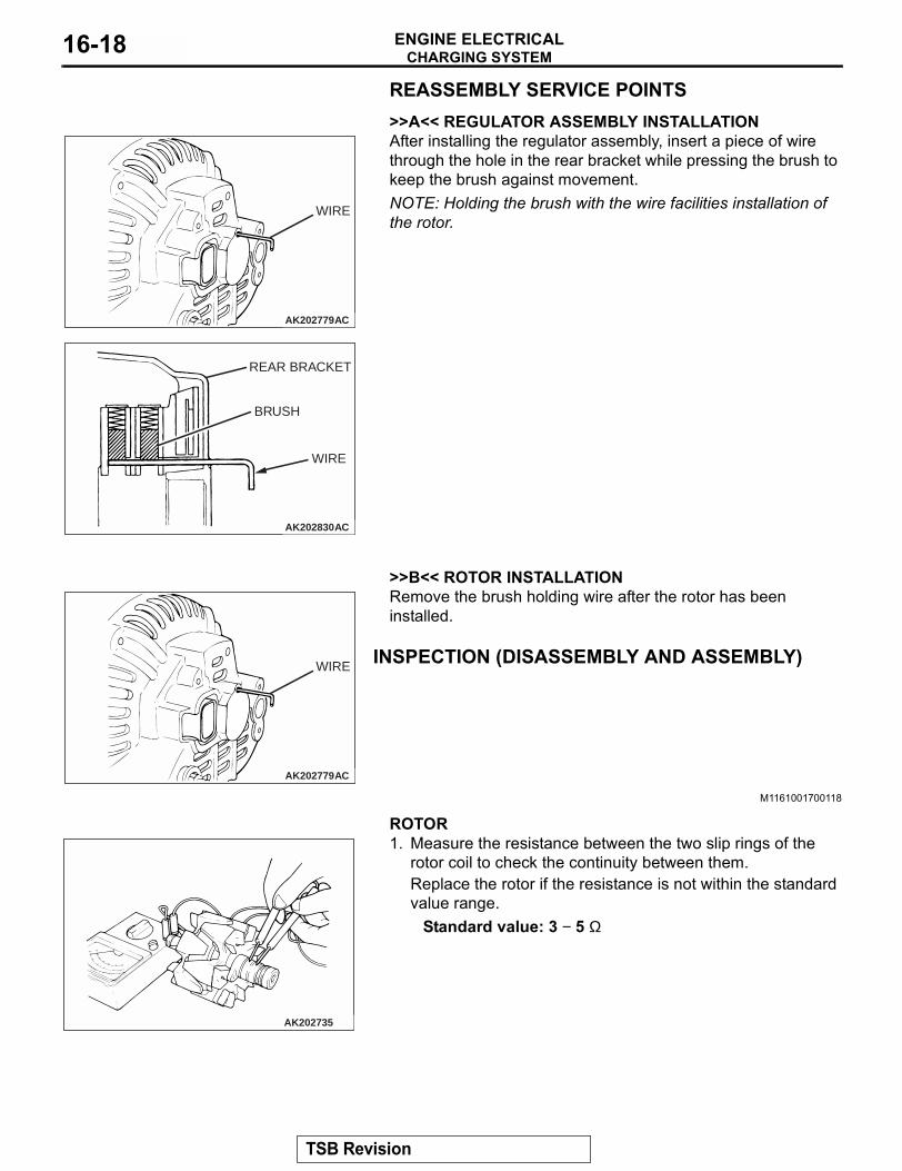
REASSEMBLY SERVICE POINTS.>>A<< REGULATOR ASSEMBLY INSTALLATIONAfter installing the regulator assembly, insert a piece of wire through the hole in the rear bracket while pressing the brush to keep the brush against movement.NOTE: Holding the brush with the wire facilities installation of the rotor.
.
>>B<< ROTOR INSTALLATIONRemove the brush holding wire after the rotor has been installed.
INSPECTION (DISASSEMBLY AND ASSEMBLY)
M1161001700118.
ROTOR1. Measure the resistance between the two slip rings of the
rotor coil to check the continuity between them.Replace the rotor if the resistance is not within the standard value range.
Standard value: 3 − 5 Ω
AK202779
WIRE
AC
AK202830
REAR BRACKET
BRUSH
WIRE
AC
AK202779
WIRE
AC
AK202735
TSB Revision
CHARGING SYSTEMENGINE ELECTRICAL 16-19
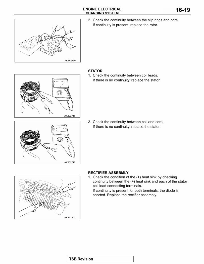
2. Check the continuity between the slip rings and core.If continuity is present, replace the rotor.
.
STATOR1. Check the continuity between coil leads.
If there is no continuity, replace the stator.
2. Check the continuity between coil and core.If there is no continuity, replace the stator.
.
RECTIFIER ASSEBMLY1. Check the condition of the (+) heat sink by checking
continuity between the (+) heat sink and each of the stator coil lead connecting terminals.If continuity is present for both terminals, the diode is shorted. Replace the rectifier assembly.
AK202736
AK202716
AK202717
AK202803
TSB Revision
CHARGING SYSTEMENGINE ELECTRICAL16-20
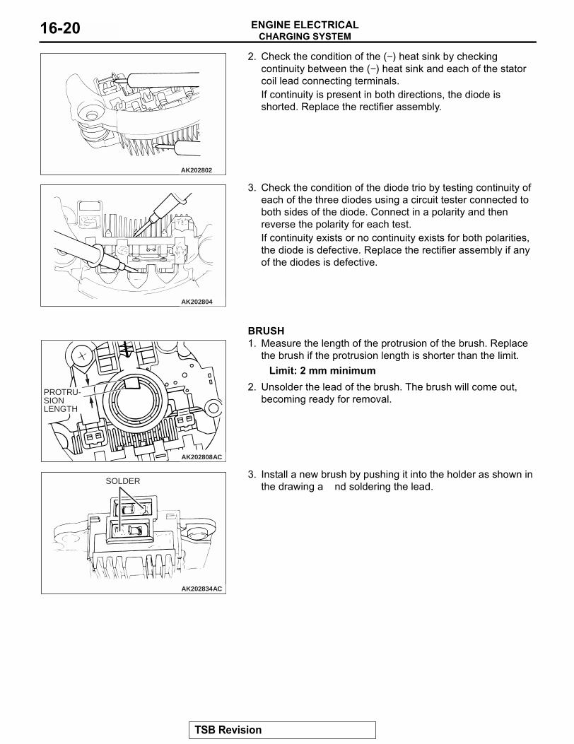
2. Check the condition of the (−) heat sink by checking continuity between the (−) heat sink and each of the stator coil lead connecting terminals.If continuity is present in both directions, the diode is shorted. Replace the rectifier assembly.
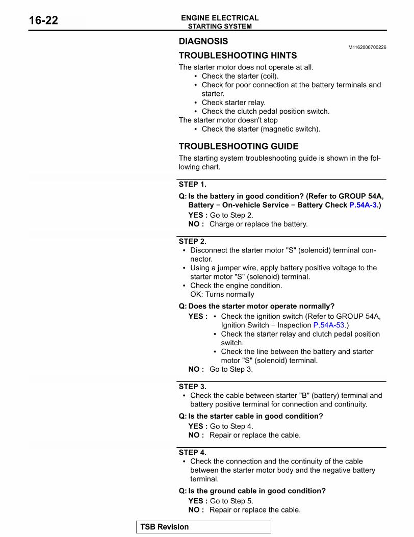
3. Check the condition of the diode trio by testing continuity of each of the three diodes using a circuit tester connected to both sides of the diode. Connect in a polarity and then reverse the polarity for each test.If continuity exists or no continuity exists for both polarities, the diode is defective. Replace the rectifier assembly if any of the diodes is defective.
.
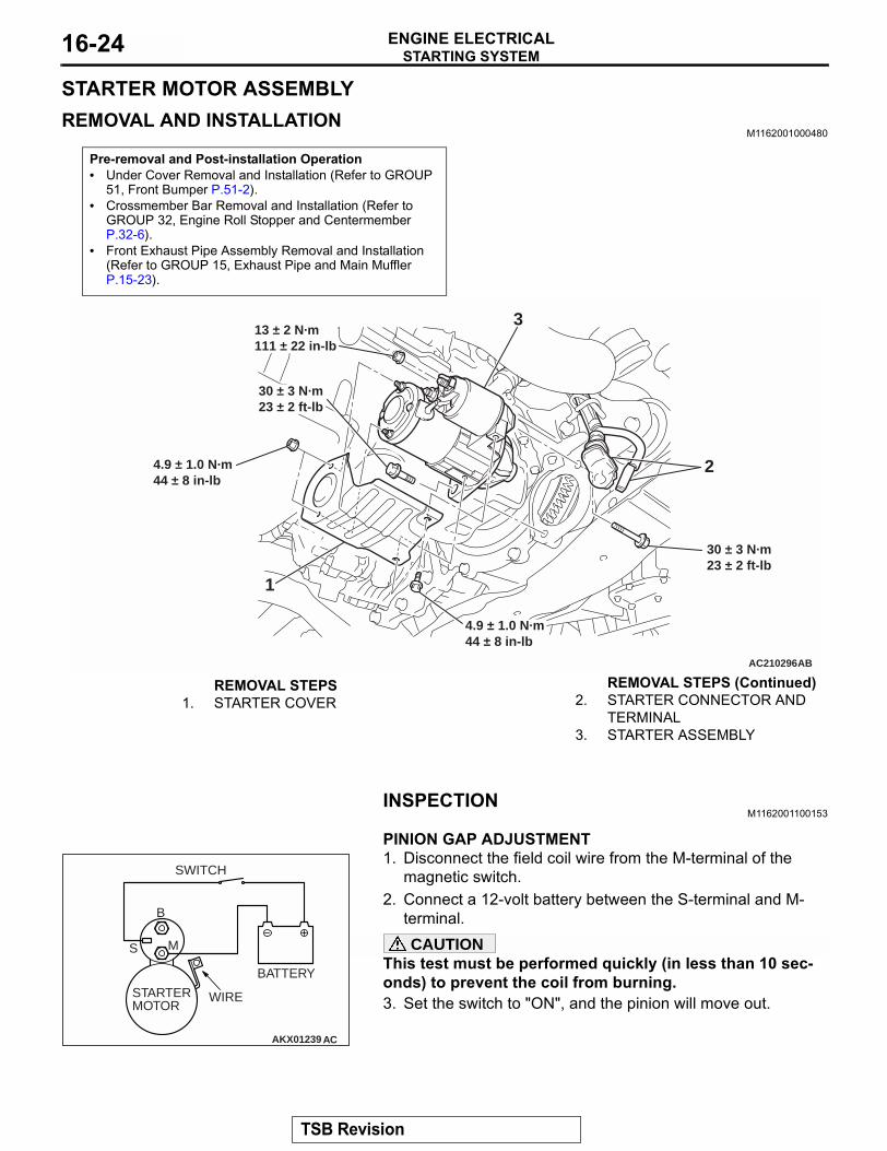
BRUSH1. Measure the length of the protrusion of the brush. Replace
the brush if the protrusion length is shorter than the limit.Limit: 2 mm minimum
2. Unsolder the lead of the brush. The brush will come out, becoming ready for removal.
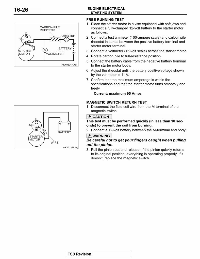
3. Install a new brush by pushing it into the holder as shown in the drawing a nd soldering the lead.
AK202802
AK202804
AK202808
PROTRU-SION LENGTH
AC
AK202834
SOLDER
AC
TSB Revision

STARTING SYSTEMENGINE ELECTRICAL 16-21
STARTING SYSTEMGENERAL DESCRIPTION
M1162000100172
If the ignition switch is turned to the "START" posi-tion, current flows in the coil provided inside mag-netic switch, attracting the plunger. When the plunger is attracted, the lever connected to the plunger is actuated to engage the overrunning clutch with the ring gear.At the same time, attracting the plunger will turn on the magnetic switch, allowing the B terminal and M terminal to conduct. Thus, current flows to engage the starter motor.
When the ignition switch is returned to the "ON" posi-tion after starting the engine, the overrunning clutch is disengaged from the ring gear.An overrunning clutch is provided between the pinion and the armature shaft, to prevent damage to the starter.
OPERATION• The clutch pedal position switch contact is
switched OFF when the clutch pedal is depressed. When the ignition switch is then switched to the "ST" position, electricity flows to the starter relay and the starter motor, the contact (magnetic switch) of the starter is switched ON and the starter motor is activated.
NOTE: If the ignition switch is switched to the "ST" position without the clutch pedal being depressed, electricity flows to the starter relay (coil), the clutch pedal position switch (contacts) and to ground, with the result that the contacts of the starter relay are switched OFF, and because the power to the starter motor is thereby inter-rupted, the starter motor in not activated.
AK202970
PULL-IN COIL
HOLDINGCOIL
PLUNGER
LEVER
PINION GEAR
OVERRUNNINGCLUTCH
YOKE
BRUSH
ARMATURE
IGNITIONSWITCH
BATTERY
+
–
AC
B
MS
TSB Revision
STARTING SYSTEMENGINE ELECTRICAL16-22
DIAGNOSISM1162000700226
TROUBLESHOOTING HINTSThe starter motor does not operate at all.
• Check the starter (coil).• Check for poor connection at the battery terminals and
starter.• Check starter relay.• Check the clutch pedal position switch.
The starter motor doesn't stop• Check the starter (magnetic switch).
TROUBLESHOOTING GUIDEThe starting system troubleshooting guide is shown in the fol-lowing chart.
STEP 1.Q: Is the battery in good condition? (Refer to GROUP 54A,
Battery − On-vehicle Service − Battery Check P.54A-3.)YES : Go to Step 2.NO : Charge or replace the battery.
STEP 2.• Disconnect the starter motor "S" (solenoid) terminal con-
nector.• Using a jumper wire, apply battery positive voltage to the
starter motor "S" (solenoid) terminal.• Check the engine condition.
OK: Turns normallyQ: Does the starter motor operate normally?
YES : • Check the ignition switch (Refer to GROUP 54A, Ignition Switch − Inspection P.54A-53.)
• Check the starter relay and clutch pedal position switch.
• Check the line between the battery and starter motor "S" (solenoid) terminal.
NO : Go to Step 3.
STEP 3.• Check the cable between starter "B" (battery) terminal and
battery positive terminal for connection and continuity.Q: Is the starter cable in good condition?
YES : Go to Step 4.NO : Repair or replace the cable.
STEP 4.• Check the connection and the continuity of the cable
between the starter motor body and the negative battery terminal.
Q: Is the ground cable in good condition?YES : Go to Step 5.NO : Repair or replace the cable.
TSB Revision

STARTING SYSTEMENGINE ELECTRICAL 16-23
STEP 5.Q: Is the starter motor in good condition? (Refer to Starting
system − Starter motor − Inspection P.16-24.)YES : Starter motor is normal. Check the excessive
rotational resistance of the engine.NO : Replace the starter motor.
ON-VEHICLE SERVICE
STARTER RELAY CHECKM1162001400176
BATTERY VOLTAGE
TERMINAL NUMBER TO BE CONNECTED TO TESTER
CONTINUITY TEST RESULTS
Not applied 2 − 5 Open circuit
• Connect terminal 1 to the positive battery terminal
• Connect terminal 3 to the negative battery terminal
2 − 5 Less than 2 ohms
AC210410
2 3
4
5
15
13
2
AC208874
AB
BATTERY
RELAY BOX
TSB Revision
STARTING SYSTEMENGINE ELECTRICAL16-24
STARTER MOTOR ASSEMBLYREMOVAL AND INSTALLATION
M1162001000480
INSPECTIONM1162001100153
.
PINION GAP ADJUSTMENT1. Disconnect the field coil wire from the M-terminal of the
magnetic switch.2. Connect a 12-volt battery between the S-terminal and M-
terminal.CAUTION
This test must be performed quickly (in less than 10 sec-onds) to prevent the coil from burning.3. Set the switch to "ON", and the pinion will move out.
Pre-removal and Post-installation Operation• Under Cover Removal and Installation (Refer to GROUP
51, Front Bumper P.51-2).• Crossmember Bar Removal and Installation (Refer to
GROUP 32, Engine Roll Stopper and Centermember P.32-6).
• Front Exhaust Pipe Assembly Removal and Installation (Refer to GROUP 15, Exhaust Pipe and Main Muffler P.15-23).
AC210296
3
2
1
AB
4.9 ± 1.0 N·m44 ± 8 in-lb
30 ± 3 N·m23 ± 2 ft-lb
30 ± 3 N·m23 ± 2 ft-lb
13 ± 2 N·m111 ± 22 in-lb
4.9 ± 1.0 N·m44 ± 8 in-lb
REMOVAL STEPS1. STARTER COVER 2. STARTER CONNECTOR AND
TERMINAL3. STARTER ASSEMBLY
REMOVAL STEPS (Continued)
AKX01239
B
MS
BATTERY
SWITCH
STARTER MOTOR
WIRE
AC
TSB Revision

STARTING SYSTEMENGINE ELECTRICAL 16-25
4. Check the pinion-to-stopper clearance (pinion gap) with a feeler gauge.
Standard value: 0.5 − 2.0 mm (0.02 − 0.07 inch)
5. If the pinion gap is out of specification, adjust by adding or removing gasket(s) between the magnetic switch and front bracket.
.
MAGNETIC SWITCH PULL-IN TEST1. Disconnect the field coil wire from the M-terminal of the
magnetic switch.CAUTION
This test must be performed quickly (in less than 10 sec-onds) to prevent the coil from burning.2. Connect a 12-volt battery between the S-terminal and M-
terminal.3. If the pinion moves out, the pull-in coil is good. If it doesn't,
replace the magnetic switch.
.
MAGNETIC SWITCH HOLD-IN TEST1. Disconnect the field coil wire from the M-terminal of the
magnetic switch.CAUTION
This test must be performed quickly (in less than 10 sec-onds) to prevent the coil from burning.2. Connect a 12-volt battery between the S-terminal and body.3. Manually pull out the pinion as far as the pinion stopper
position.4. If the pinion remains out, everything is operating properly. If
the pinion moves in, the hold-in circuit is open. Replace the magnetic switch.
.
AKX00198
STOPPER
PINION GAP
PINION
AB
AKX00199
AKX01243
B
MS
BATTERY
STARTER MOTOR
WIRE
AC
AKX01245
B
MS
BATTERYSTARTER MOTOR
WIRE
AC
TSB Revision
STARTING SYSTEMENGINE ELECTRICAL16-26
FREE RUNNING TEST1. Place the starter motor in a vise equipped with soft jaws and
connect a fully-charged 12-volt battery to the starter motor as follows:
2. Connect a test ammeter (100-ampere scale) and carbon pile rheostat in series between the positive battery terminal and starter motor terminal.
3. Connect a voltmeter (15-volt scale) across the starter motor.4. Rotate carbon pile to full-resistance position.5. Connect the battery cable from the negative battery terminal
to the starter motor body.6. Adjust the rheostat until the battery positive voltage shown
by the voltmeter is 11 V.7. Confirm that the maximum amperage is within the
specifications and that the starter motor turns smoothly and freely.
Current: maximum 95 Amps.
MAGNETIC SWITCH RETURN TEST1. Disconnect the field coil wire from the M-terminal of the
magnetic switch.CAUTION
This test must be performed quickly (in less than 10 sec-onds) to prevent the coil from burning.2. Connect a 12-volt battery between the M-terminal and body.
WARNINGBe careful not to get your fingers caught when pulling out the pinion.3. Pull the pinion out and release. If the pinion quickly returns
to its original position, everything is operating properly. If it doesn't, replace the magnetic switch.
AKX01247
B
MS
CARBON-PILE RHEOSTAT
AMMETER
BATTERYSTARTER MOTOR VOLTMETER
AC
A
V
AKX01249
B
MS
BATTERY
STARTER MOTOR
WIRE
AC
TSB Revision
STARTING SYSTEMENGINE ELECTRICAL 16-27
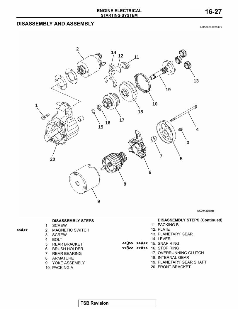
DISASSEMBLY AND ASSEMBLYM1162001200172
AK204335AB
1412 11
13
19
10
18
171615
20
2
9
8
6
4
7 5
3
1
DISASSEMBLY STEPS1. SCREW
<<A>> 2. MAGNETIC SWITCH3. SCREW4. BOLT5. REAR BRACKET6. BRUSH HOLDER7. REAR BEARING8. ARMATURE9. YOKE ASSEMBLY10. PACKING A
11. PACKING B12. PLATE13. PLANETARY GEAR14. LEVER
<<B>> >>A<< 15. SNAP RING<<B>> >>A<< 16. STOP RING
17. OVERRUNNING CLUTCH18. INTERNAL GEAR19. PLANETARY GEAR SHAFT20. FRONT BRACKET
DISASSEMBLY STEPS (Continued)
TSB Revision

STARTING SYSTEMENGINE ELECTRICAL16-28
DISASSEMBLY SERVICE POINTS.<<A>> MAGNETIC SWITCH REMOVAL
CAUTIONDo not clamp the yoke assembly with a vise.Disconnect the lead from the M terminal of the magnetic switch.
.
<<B>> SNAP RING/STOP RING REMOVAL1. Apply a long socket wrench of an appropriate size to the
stop ring and strike the wrench to drive out the stop ring toward the pinion gear side.
2. Remove the snap ring with snap ring pliers, then remove the stop ring and overrunning clutch.
STARTER MOTOR PARTS CLEANING.
1. Never clean in a solvent such starter motor parts as the magnetic switch, brush holder, and armature. If they are soaked in a solvent, their insulation could be impaired. When these parts require cleaning, wipe off contamination with cloth.
2. Never soak the drive unit in a solvent. If it is washed in a solvent, the grease having been packed in the overrunning clutch at the factory will be washed out. Wipe the drive unit with cloth if it requires cleaning.
AK202890
B TERMINAL
M TERMINAL
S TERMINAL
FIELD COIL LEAD
AC
AK202790
SOCKET WRENCH
STOP RING PINION GEAR
OVERRUNNING CLUTCH
AC
AK202791
SNAP RING PLIERS
SNAP RING
PINION GEAR
OVERRUNNING CLUTCH
AC
TSB Revision

STARTING SYSTEMENGINE ELECTRICAL 16-29
REASSEMBLY SERVICE POINTS.
>>A<< STOP RING/SNAP RING INSTALLATIONUse a suitable puller to pull the stop ring until it gets over the snap ring.
INSPECTION (DISASSEMBLY AND ASSEMBLY)
M1162001300124.
COMMUTATOR1. Support the armature with a pair of V block and turn it to
measure the runout of the surface not rubbed by the brushes using a dial gauge.
Standard value: 0.05 mm or lessLimit: 0.1 mm
2. Measure the diameter of the commutator.Standard value: 29.4 mmLimit: 28.8 mm
3. Measure the depth of the undercut between segments.Standard value: 0.5 mmLimit: 0.2 mm
.
AK202911
OVERRUNNING CLUTCH
STOP RING
SNAP RING
STOP RING
AC
AK202712
AK202715
AK202711
SEGMENT UNDERCUT
MICA
AC
TSB Revision
STARTING SYSTEMENGINE ELECTRICAL16-30
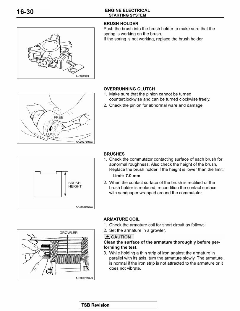
BRUSH HOLDERPush the brush into the brush holder to make sure that the spring is working on the brush.If the spring is not working, replace the brush holder.
.
OVERRUNNING CLUTCH1. Make sure that the pinion cannot be turned
counterclockwise and can be turned clockwise freely.2. Check the pinion for abnormal ware and damage.
.
BRUSHES1. Check the commutator contacting surface of each brush for
abnormal roughness. Also check the height of the brush. Replace the brush holder if the height is lower than the limit.
Limit: 7.0 mm2. When the contact surface of the brush is rectified or the
brush holder is replaced, recondition the contact surface with sandpaper wrapped around the commutator.
.
ARMATURE COIL1. Check the armature coil for short circuit as follows:2. Set the armature in a growler.
CAUTIONClean the surface of the armature thoroughly before per-forming the test.3. While holding a thin strip of iron against the armature in
parallel with its axis, turn the armature slowly. The armature is normal if the iron strip is not attracted to the armature or it does not vibrate.
AK204343
AK202710
FREE
LOCK
AC
AK202846
BRUSH HEIGHT
AC
AK202733
GROWLER
AB
TSB Revision

STARTING SYSTEMENGINE ELECTRICAL 16-31
4. Check the insulation between commutator segments and armature coils. The armature coils are properly insulated if no continuity is present.
5. Check continuity between a segment and another. There is no open circuit in the tested coil if there is continuity.
.
MAGNETIC SWITCH1. Coil open circuit test• Check that there is continuity between the M terminal and
body A.• If there is no continuity, replace the magnetic switch.
2. Contact fusion check• Check that there is no continuity between the B terminal
and M terminal.• If there is continuity, replace the magnetic switch.
AK202734
AK202713
AK202891
A
M
AC
AK202892
M TERMINAL
B TERMINAL
AC
TSB Revision

IGNITION SYSTEMENGINE ELECTRICAL16-32
3. Switch contact check• Push the indicated end of the magnetic switch with a strong
force to close the internal contacts. Without releasing the switch end, check that there is continuity between the B ter-minal and M terminal.
• If there is no continuity, replace the magnetic switch.
IGNITION SYSTEMGENERAL DESCRIPTION
M1163000100227
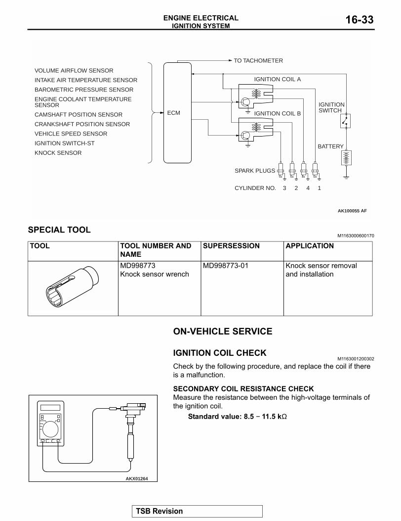
This system is provided with two ignition coils (A and B) with built-in ignition power transistors for the num-ber 1 and number 4 cylinders, and number 2 and number 3 cylinders respectively. Interruption of the current flowing in the primary side of ignition coil A generates a high voltage in the sec-ondary side of ignition coil A.The high voltage generated is applied to the spark plugs of number 1 and number 4 cylinders to gener-ate sparks. At the time that the sparks are generated at both spark plugs, if one cylinder is at the compres-sion stroke, the other cylinder is at the exhaust stroke, so that ignition of the compressed air/fuel mixture occurs only for the cylinder which is on the compression stroke.In the same way, when the primary current flowing in ignition coil B is interrupted, the high voltage thus generated is applied to the spark plugs of number 2 and number 3 cylinders.
The engine control module controls the two ignition power transistors to turn them alternately ON and OFF. This causes the primary currents in the ignition coils to be alternately interrupted and allowed to flow to fire the cylinders in the order 1 − 3 − 4 − 2.The engine control module determines which ignition coil should be controlled by means of the signals from the camshaft position sensor and from the crankshaft position sensor.It also detects the crankshaft position in order to pro-vide ignition at the most appropriate timing in response to the engine operation conditions.When the engine is cold or operated at high alti-tudes, the ignition timing is slightly advanced to pro-vide optimum performance.
AK202893
M TERMINAL
B TERMINAL
AC
TSB Revision
IGNITION SYSTEMENGINE ELECTRICAL 16-33
SPECIAL TOOLM1163000600170
ON-VEHICLE SERVICE
IGNITION COIL CHECK M1163001200302
Check by the following procedure, and replace the coil if there is a malfunction..
SECONDARY COIL RESISTANCE CHECKMeasure the resistance between the high-voltage terminals of the ignition coil.
Standard value: 8.5 − 11.5 kΩ
.
AK100055
INTAKE AIR TEMPERATURE SENSOR
BAROMETRIC PRESSURE SENSOR
CAMSHAFT POSITION SENSOR
CRANKSHAFT POSITION SENSOR
VEHICLE SPEED SENSOR
IGNITION SWITCH-ST
KNOCK SENSOR
ENGINE COOLANT TEMPERATURESENSOR
VOLUME AIRFLOW SENSOR
ECM
TO TACHOMETER
IGNITION COIL A
IGNITION COIL B
IGNITIONSWITCH
BATTERY
SPARK PLUGS
CYLINDER NO. 3 2 4 1
AF
TOOL TOOL NUMBER AND NAME
SUPERSESSION APPLICATION
MD998773Knock sensor wrench
MD998773-01 Knock sensor removal and installation
AKX01264
TSB Revision

IGNITION SYSTEMENGINE ELECTRICAL16-34
PRIMARY COIL AND IGNITION POWER TRANSISTOR CONTINUITY CHECK
NOTE: An analog-type ohmmeter should be used.NOTE: Connect the negative probe of the ohmmeter to termi-nal No. 1.
CAUTIONThis test must be performed quickly (in less than 10 sec-onds) to prevent coil from burning and ignition power tran-sistor from breaking.1. Connect and disconnect 1.5 V battery between terminals
No. 2 and No. 3, and observe the ohmmeter whether there is continuity or not.
2. If results do not agree with the table below, replace the primary coil and ignition power transistor assembly.
SPARK PLUG CABLE RESISTANCE CHECKM1163001400072
Measure the resistance of the all spark plug leads.1. Check the cap and coating for cracks.2. Measure the resistance.
Limit: 19 kΩ3. If resistance is greater than 19 kΩ, replace the cable.
AKX01265AB
1.5 V
1 2 3+–
1.5 V POWER SUPPLYBETWEEN 2 − 3
CONTINUITY BETWEEN 1 − 2
Current flowing Yes
Current not flowing No
AKX00382
TSB Revision

IGNITION SYSTEMENGINE ELECTRICAL 16-35
SPARK PLUG CHECK AND CLEANING M1163004300278
CAUTION• Do not attempt to adjust the gap of the iridium plug.• Cleaning of the iridium plug may result in damage to
the iridium and platinum tips. Therefore, if carbon deposits must be removed, use a plug cleaner and complete cleaning within 20 seconds to protect the electrode. Do not use a wire brush.
Check the plug gap and replace if the limit is exceeded.Standard value: 0.7 − 0.8 mm (0.028 − 0.031 inch)Limit: 1.0 mm (0.039 inch)
CAMSHAFT POSITION SENSOR CHECKM1163004400101
Refer to GROUP 13A, Diagnostic Trouble Code Procedures − DTC 0340: Camshaft Position Sensor Circuit P.13A-317.
CRANK ANGLE SENSOR CHECKM1163004500120
Refer to GROUP 13A, Diagnostic Trouble Code Procedures − DTC P335: Crankshaft Position Sensor Circuit P.13A-302.
IGNITION SECONDARY VOLTAGE WAVE PATTERN CHECK USING AN OSCILLOSCOPE
M1163001700125.
MEASUREMENT METHOD1. Clamp the spark plug cable (Number 1 or 3) with the
secondary pickup.NOTE: Because of the two-cylinder simultaneous ignition system, the waves for two cylinders in each group appear during wave observation. However, wave observation is car-ried out for the cylinder (Number 1 or 3) with the spark plug cable which has been clamped by the secondary pickup.NOTE: Identification of which cylinder wave pattern is dis-played can be difficult, but the wave pattern of the cylinder which is clamped by the secondary pickup will be stable, so this can be used as a reference.
2. Clamp the spark plug cable (Number 1 or 3) with the trigger pickup.NOTE: Clamp the same spark plug cable as the one which has been clamped by the secondary pickup.
.
AKX01327AB
IRIDIUMTIP
PLATINUMTIP
TSB Revision

IGNITION SYSTEMENGINE ELECTRICAL16-36
STANDARD WAVE PATTERNSETTINGSFUNCTION SECONDARYPattern height High (or low)
Pattern selector Raster
Engine speed Curb idle speed
SETTINGSPattern selector Display
Pattern height High (or low)
Engine speed Curb idle speed
AKX00278
kV
0
SECONDARYIGNITIONVOLTAGEWAVE PATTERN
IGNITION VOLTAGE(POINT D)
SPARK LINE (POINT A)
DWELL SECTION
WAVE DAMPING REDUCTION SECTION (POINT B)
POINT C
TIME
AB
TSB Revision

IGNITION SYSTEMENGINE ELECTRICAL 16-37
.
ABNORMAL WAVEFORMS EXAMPLESExample 1• Wave characteristics
Spark line is high and short.• Cause of problem
Spark plug gap is too large.
Example 2• Wave characteristics
Spark line is low and long, and is sloping. Also, the second half of the spark line is distorted. This could be a result of misfiring.
• Cause of problemSpark plug gap is too small.
Example 3• Wave characteristics
Spark line is low and long, and is sloping. However, there is almost no spark line distortion.
• Cause of problemSpark plug gap is fouled.
AKX01275
kV
SECONDARY IGNITIONVOLTAGE WAVE PATTERN
0
2
NO. 1 CYLINDER NO. 3 CYLINDERIGNITION NOISE
NEUTRAL SECTION
NO. 4 CYLINDERNO. 2 CYLINDER IGNITION NOISE
TIME
AB
AKX00280
AKX00281
AKX00282
TSB Revision
IGNITION SYSTEMENGINE ELECTRICAL16-38
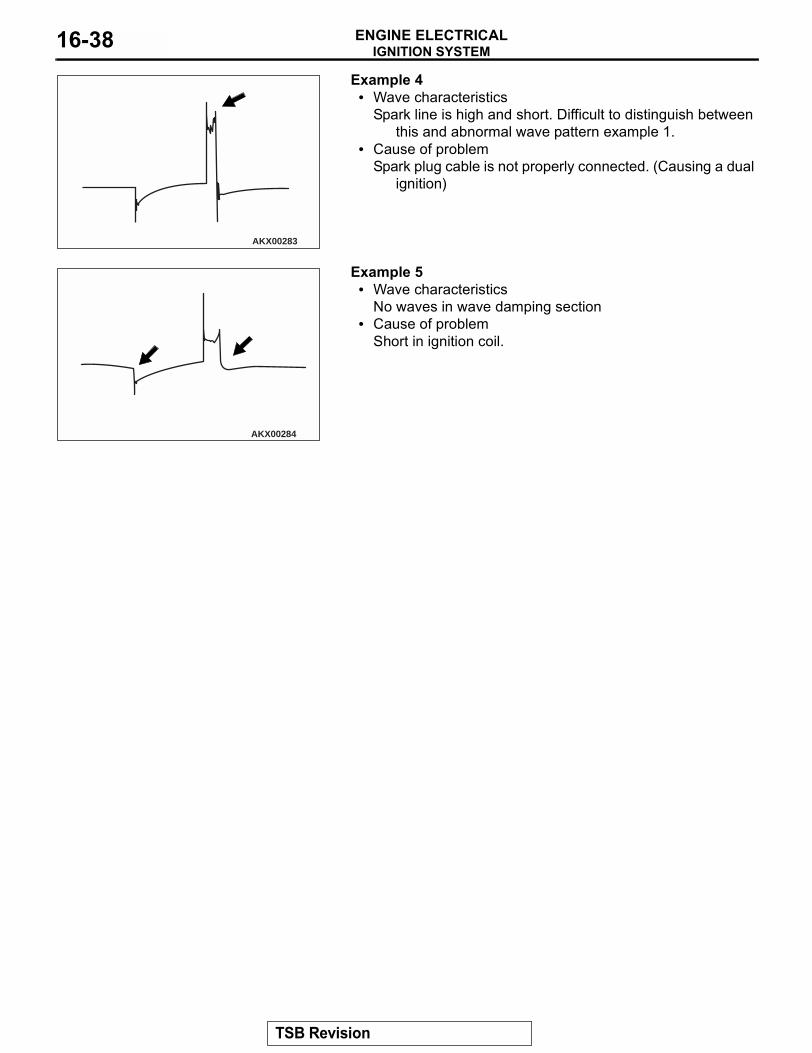
Example 4• Wave characteristics
Spark line is high and short. Difficult to distinguish between this and abnormal wave pattern example 1.
• Cause of problemSpark plug cable is not properly connected. (Causing a dual
ignition)
Example 5• Wave characteristics
No waves in wave damping section• Cause of problem
Short in ignition coil.
AKX00283
AKX00284
TSB Revision
IGNITION SYSTEMENGINE ELECTRICAL 16-39
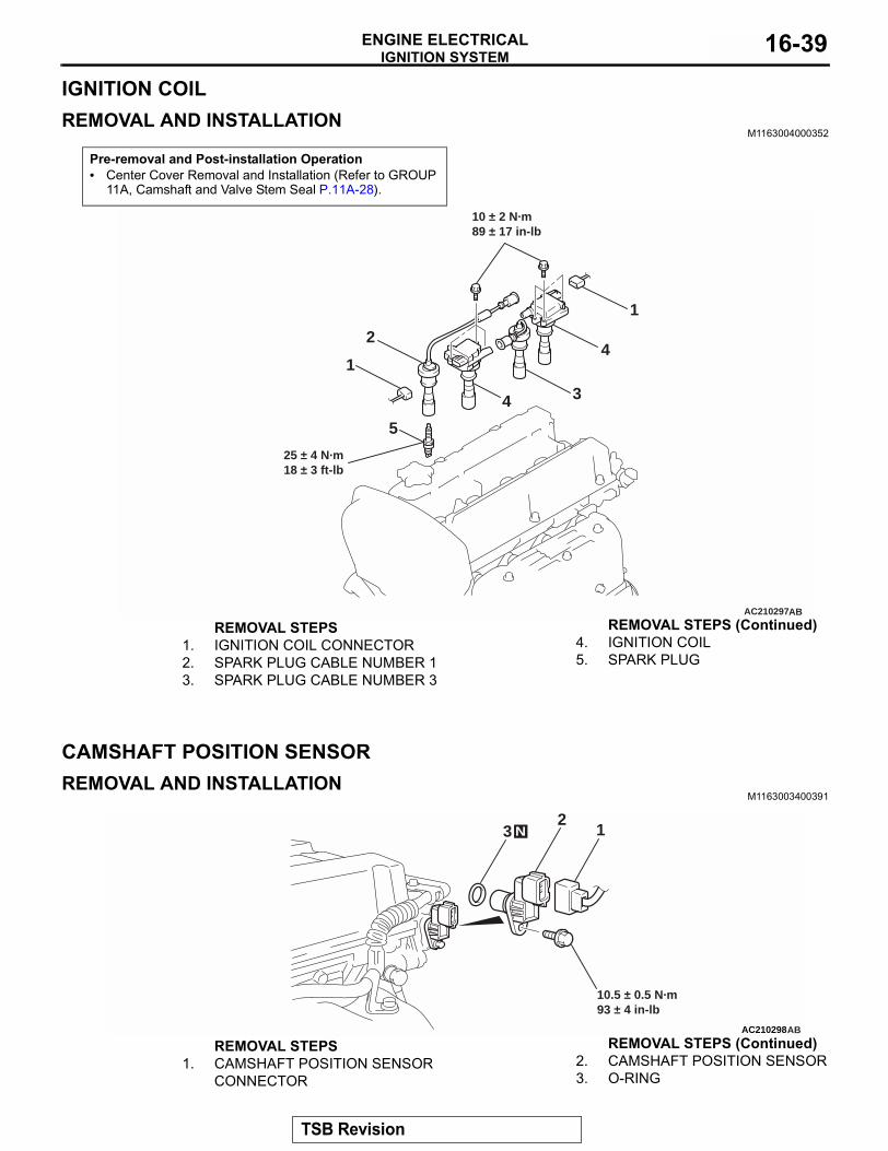
IGNITION COILREMOVAL AND INSTALLATION
M1163004000352
CAMSHAFT POSITION SENSORREMOVAL AND INSTALLATION
M1163003400391
Pre-removal and Post-installation Operation• Center Cover Removal and Installation (Refer to GROUP
11A, Camshaft and Valve Stem Seal P.11A-28).
AC210297
1
1
42
34
10 ± 2 N·m89 ± 17 in-lb
25 ± 4 N·m18 ± 3 ft-lb
AB
5
REMOVAL STEPS1. IGNITION COIL CONNECTOR2. SPARK PLUG CABLE NUMBER 13. SPARK PLUG CABLE NUMBER 3
4. IGNITION COIL5. SPARK PLUG
REMOVAL STEPS (Continued)
AC210298
12
3
10.5 ± 0.5 N·m93 ± 4 in-lb
AB
N
REMOVAL STEPS1. CAMSHAFT POSITION SENSOR
CONNECTOR2. CAMSHAFT POSITION SENSOR3. O-RING
REMOVAL STEPS (Continued)
TSB Revision

IGNITION SYSTEMENGINE ELECTRICAL16-40
CRANKSHAFT POSITION SENSORREMOVAL AND INSTALLATION
M1163003500376
CAUTIONIf the vehicle is equipped with the Brembo disc brake, during maintenance, take care not to contact the parts or tools to the caliper because the paint of caliper will be scratched.
Pre-removal and Post-installation Operation• Timing Belt Removal and Installation (Refer to GROUP
11A,Timing Belt P.11A-50).• Radiator Reserve Tank Assembly Removal and Installa-
tion (Refer to GROUP 14, Radiator P.14-22).
AC210409
1
5
6
AB
2
22 ± 4 N·m16 ± 3 ft-lb
22 ± 4 N·m16 ± 3 ft-lb
3440 ± 5 N·m30 ± 3 ft-lb
22 ± 4 N·m16 ± 3 ft-lb
12 ± 2 N·m102 ± 2 in-lb
12 ± 2 N·m102 ± 2 in-lb
49 ± 9 N·m36 ± 7 ft-lb
49 ± 9 N·m36 ± 7 ft-lb
8.8 ± 1.0 N·m78 ± 9 in-lb
REMOVAL STEPS1. POWER STEERING PRESSURE
SWITCH CONNECTOR2. POWER STEERING OIL PUMP
HEAT PROTECTOR<<A>> 3. POWER STEERING OIL PUMP,
BRACKET AND OIL RESERVOIR ASSEMBLY
4. POWER STEERING OIL PUMP BRACKET
5. CRANKSHAFT POSITION SENSOR CONNECTOR
6. CRANKSHAFT POSITION SENSOR
REMOVAL STEPS (Continued)
TSB Revision

IGNITION SYSTEMENGINE ELECTRICAL 16-41
REMOVAL SERVICE POINT.
<<A>> POWER STEERING OIL PUMP, BRACKET AND OIL RESERVOIR ASSEMBLY REMOVALNOTE: Tie the removed power steering oil pump, bracket and oil reservoir assembly with a rope and set aside where they cannot hinder the removal of the power steering oil pump bracket.Remove the power steering oil pump, bracket and oil reservoir assembly with the hoses attached from the power steering oil pump bracket.
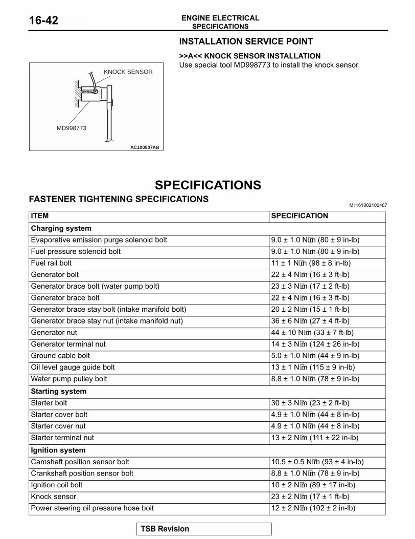
KNOCK SENSORREMOVAL AND INSTALLATION
M1163002800426
Required Special Tool:• MD998773: Knock sensor wrench
REMOVAL SERVICE POINT.
<<A>> KNOCK SENSOR REMOVALUse special tool MD998773 to remove the knock sensor.
Pre-removal and Post-installation Operation• Intake Manifold Stay Removal and Installation (Refer to
GROUP 15,Intake Manifold P.15-13).
AC210411AB
23 ± 2 N·m17 ± 1 ft-lb
12
INTAKE MANIFOLD STAY
REMOVAL1. KNOCK SENSOR CONNECTOR
<<A>> >>A<< 2. KNOCK SENSOR
AC100807
MD998773
KNOCK SENSOR
AB
TSB Revision
SPECIFICATIONSENGINE ELECTRICAL16-42
INSTALLATION SERVICE POINT.>>A<< KNOCK SENSOR INSTALLATIONUse special tool MD998773 to install the knock sensor.
SPECIFICATIONSFASTENER TIGHTENING SPECIFICATIONS
M1161002100487
AC100807
MD998773
KNOCK SENSOR
AB
ITEM SPECIFICATIONCharging systemEvaporative emission purge solenoid bolt 9.0 ± 1.0 N⋅m (80 ± 9 in-lb)Fuel pressure solenoid bolt 9.0 ± 1.0 N⋅m (80 ± 9 in-lb)Fuel rail bolt 11 ± 1 N⋅m (98 ± 8 in-lb)Generator bolt 22 ± 4 N⋅m (16 ± 3 ft-lb)Generator brace bolt (water pump bolt) 23 ± 3 N⋅m (17 ± 2 ft-lb)Generator brace bolt 22 ± 4 N⋅m (16 ± 3 ft-lb)Generator brace stay bolt (intake manifold bolt) 20 ± 2 N⋅m (15 ± 1 ft-lb)Generator brace stay nut (intake manifold nut) 36 ± 6 N⋅m (27 ± 4 ft-lb)Generator nut 44 ± 10 N⋅m (33 ± 7 ft-lb)Generator terminal nut 14 ± 3 N⋅m (124 ± 26 in-lb)Ground cable bolt 5.0 ± 1.0 N⋅m (44 ± 9 in-lb)Oil level gauge guide bolt 13 ± 1 N⋅m (115 ± 9 in-lb)Water pump pulley bolt 8.8 ± 1.0 N⋅m (78 ± 9 in-lb)Starting systemStarter bolt 30 ± 3 N⋅m (23 ± 2 ft-lb)Starter cover bolt 4.9 ± 1.0 N⋅m (44 ± 8 in-lb)Starter cover nut 4.9 ± 1.0 N⋅m (44 ± 8 in-lb)Starter terminal nut 13 ± 2 N⋅m (111 ± 22 in-lb)Ignition systemCamshaft position sensor bolt 10.5 ± 0.5 N⋅m (93 ± 4 in-lb)Crankshaft position sensor bolt 8.8 ± 1.0 N⋅m (78 ± 9 in-lb)Ignition coil bolt 10 ± 2 N⋅m (89 ± 17 in-lb)Knock sensor 23 ± 2 N⋅m (17 ± 1 ft-lb)Power steering oil pressure hose bolt 12 ± 2 N⋅m (102 ± 2 in-lb)
TSB Revision

SPECIFICATIONSENGINE ELECTRICAL 16-43
GENERAL SPECIFICATIONSM1161000200239
SERVICE SPECIFICATIONSM1161000300281
Power steering oil pump bracket bolt (cylinder block side) 49 ± 9 N⋅m (36 ± 7 in-lb)Power steering oil pump bracket bolt (power steering oil pump side)
M8 22 ± 4 N⋅m (16 ± 3 ft-lb)M10 40 ± 5 N⋅m (30 ± 3 ft-lb)
Power steering oil pump heat protector bolt 22 ± 4 N⋅m (16 ± 3 in-lb)Power steering oil reservoir bolt 12 ± 2 N⋅m (102 ± 2 in-lb)Spark plug 25 ± 4 N⋅m (18 ± 3 ft-lb)
ITEM SPECIFICATION
ITEMS SPECIFICATIONSGeneratorType Positive battery positive voltage sensingIdentification number A3TB1791Part No. MD366831Rated output V/A 12/90Voltage regulator Electronic built-in typeStarter motorType Reduction drive with planetary gearIdentification number M0T31171Part No. MN128202Rated output kW/V 1.2/12Number of pinion teeth 8Ignition coilType Molded 2-coilSpark plugsNGK IGR7A-GDENSO −CHAMPION −
ITEMS STANDARD VALUE LIMITGeneratorRegulated voltage (Ambient temperature at voltage regulator)
−20°C (−4°F) 14.2 − 15.4 −20°C (68°F) 13.9 − 14.9 −60°C (140°F) 13.4 − 14.5 −80°C (176°F) 13.1 − 14.5 −
Generator output line voltage drop (at 30A) V − Maximum 0.3Output current − 70% of normal output
currentField coil resistance Ω Approximately 2 − 5 −Brush protrusion length mm (in) − Minimum 2 (0.08)
TSB Revision

SPECIFICATIONSENGINE ELECTRICAL16-44
Starter motorFree running characteristics Terminal voltage
V11 −
Current A 95 −Speed r/min 2,500 or more −
Pinion gap mm (in) 0.5 − 2.0 (0.02 − 0.07) −Commutator run-out mm (in) 0.05 (0.002) Minimum 0.1 (0.004)Commutator diameter mm (in) 29.4 (1.16) Minimum 28.8 (1.13)Undercut depth mm (in) 0.5 (0.02) Minimum 0.2 (0.008)Ignition partsIgnition secondary coil resistance at 20°C (68°F) kΩ 8.5 − 11.5 −Spark plug gap mm (in) 1.0 − 1.1 (0.039 − 0.043) −Resistor wire resistance kΩ − Maximum 19
ITEMS STANDARD VALUE LIMIT
TSB Revision