group 22c twin clutch- sportronic shift transmission (tc … · general information tsb revision...
TRANSCRIPT

22C-1
GROUP 22C
TWIN CLUTCH-SPORTRONIC SHIFT
TRANSMISSION(TC-SST)
CONTENTS
GENERAL INFORMATION . . . . . . . . 22C-3
LUBRICANT. . . . . . . . . . . . . . . . . . . . 22C-3
SPECIAL TOOLS. . . . . . . . . . . . . . . . 22C-4
DIAGNOSIS <TC-SST> . . . . . . . . . . . 22C-6INTRODUCTION. . . . . . . . . . . . . . . . . . . . . 22C-6TROUBLESHOOTING STRATEGY . . . . . . 22C-6DIAGNOSIS FUNCTION. . . . . . . . . . . . . . . 22C-6DIAGNOSTIC TROUBLE CODE CHART. . 22C-10SYMPTOM CHART. . . . . . . . . . . . . . . . . . . 22C-15DIAGNOSTIC TROUBLE CODE PROCEDURES. . . . . . . . . . . . . . . . . . . . . . 22C-15SYMPTOM PROCEDURES . . . . . . . . . . . . 22C-289DATA LIST REFERENCE TABLE . . . . . . . 22C-298TC-SST-ECU TERMINAL VOLTAGE REFERENCE CHART. . . . . . . . . . . . . . . . . 22C-299
DIAGNOSIS <SHIFT LEVER>. . . . . . 22C-300INTRODUCTION. . . . . . . . . . . . . . . . . . . . . 22C-300TROUBLESHOOTING STRATEGY . . . . . . 22C-300DIAGNOSIS FUNCTION. . . . . . . . . . . . . . . 22C-300DIAGNOSTIC TROUBLE CODE CHART. . 22C-302SYMPTOM CHART. . . . . . . . . . . . . . . . . . . 22C-302
DIAGNOSTIC TROUBLE CODE PROCEDURES . . . . . . . . . . . . . . . . . . . . . . 22C-303SYMPTOM PROCEDURES . . . . . . . . . . . . 22C-309DATA LIST REFERENCE TABLE. . . . . . . . 22C-322SPECIAL FUNCTION (ACTUATOR TEST REFERENCE TABLE). . . . . . . . . . . . . . . . . 22C-325SHIFT LEVER -ECU TERMINALVOLTAGE REFERENCE CHART . . . . . . . . . . . . . . . . . 22C-325
DIAGNOSIS <S-AWC(SUPER ALL WHEEL CONTROL)> . . . . . . . . . . . . . 22C-328
INTRODUCTION . . . . . . . . . . . . . . . . . . . . . 22C-328
ON-VEHICLE SERVICE . . . . . . . . . . . 22C-328TRANSMISSION OIL LEVEL CHECK. . . . . 22C-328TRANSMISSION OIL CHANGE . . . . . . . . . 22C-328TRANSFER OIL CHECK. . . . . . . . . . . . . . . 22C-329TRANSFER OIL CHANGE . . . . . . . . . . . . . 22C-329SHIFT LEVER OPERATION CHECK . . . . . 22C-330KEY INTERLOCK MECHANISM CHECK . . 22C-330SHIFT LOCK MECHANISM CHECK. . . . . . 22C-332FLUID CHECK. . . . . . . . . . . . . . . . . . . . . . . 22C-332BLEEDING . . . . . . . . . . . . . . . . . . . . . . . . . 22C-332ACD OPERATION CHECK . . . . . . . . . . . . . 22C-333HYDRAULIC PRESSURE CHECK . . . . . . . 22C-333
Continued on next page

22C-2
TWIN CLUTCH SST CONTROL MODE SWITCH . . . . . . . . . . . . . . . . . . . . . . . 22C-333
REMOVAL AND INSTALLATION . . . . . . . . 22C-333INSPECTION . . . . . . . . . . . . . . . . . . . . . . . 22C-333TWIN CLUTCH SST CONTROL MODE SWITCH CHECK . . . . . . . . . . . . . . . . . . . . 22C-333
TRANSMISSION CONTROL . . . . . . . 22C-334REMOVAL AND INSTALLATION . . . . . . . . 22C-334
KEY INTERLOCK AND SHIFT LOCK MECHANISMS . . . . . . . . . . . . . . . . . . 22C-337
REMOVAL AND INSTALLATION . . . . . . . . 22C-337
TRANSFER ASSEMBLY . . . . . . . . . . 22C-339REMOVAL AND INSTALLATION . . . . . . . . 22C-339
TRANSAXLE ASSEMBLY. . . . . . . . . 22C-341REMOVAL AND INSTALLATION . . . . . . . . 22C-341
OIL COOLER . . . . . . . . . . . . . . . . . . . 22C-347REMOVAL AND INSTALLATION . . . . . . . . 22C-347
PADDLE SHIFT ASSEMBLY . . . . . . . 22C-348REMOVAL AND INSTALLATION . . . . . . . . 22C-348INSPECTION. . . . . . . . . . . . . . . . . . . . . . . . 22C-348PADDLE SHIFT SWITCH CHECK . . . . . . . 22C-348
AWC-ECU . . . . . . . . . . . . . . . . . . . . . . 22C-349REMOVAL AND INSTALLATION . . . . . . . . 22C-349
SENSOR, SWITCH AND RELAY . . . . 22C-349REMOVAL AND INSTALLATION . . . . . . . . 22C-349
HYDRAULIC UNIT . . . . . . . . . . . . . . . 22C-349REMOVAL AND INSTALLATION . . . . . . . . 22C-349

GENERAL INFORMATIONTWIN CLUTCH- SPORTRONIC SHIFT TRANSMISSION (TC-SST) 22C-3
GENERAL INFORMATIONM1225000100022
LUBRICANTM1225000200018
Item SpecificationTransaxle model W6DGATransaxle type 6-speed forward, 1-speed reverse constant meshClutch Wet multiplate clutch x 2Gear ratio 1st 3.655
2nd 2.3683rd 1.7544th 1.3225th 1.0086th 0.775Reverse 4.011
Final gear ratio 4.062Helical gear LSD (front differential) PresentTransfer Reduction
ratio3.307
Differential gear unit
Hydraulic pressure multiplate clutch (ACD)
Item Brand Capacity
Transmission oil dm 3 (qt) Mitsubishi genuine Dia-Queen SSTF-I 7.1 (7.5) [Including 0.6 (0.63) in oil cooler]
Transfer oil dm 3 (qt) Mitsubishi genuine Dia-Queen LSD Gear Oil
0.8 (0.9)
AWC fluid dm 3 (qt) Mitsubishi genuine Dia-Queen ATF SPIII
1.0 (1.1)
Front propeller shaft Sleeve yoke section Mitsubishi genuine Dia-Queen Super Hypoid Gear Oil SAE 90 (GL-5)
Adequate amount
Transfer O-ring Mitsubishi genuine Dia-Queen ATF SPIIISpline section of input shaft
(outer edge) Transaxle assembly O-ring Molykote BR2-Plus
Spline sections of input shaft and flywheel
TSB Revision

SPECIAL TOOLSTWIN CLUTCH- SPORTRONIC SHIFT TRANSMISSION (TC-SST)22C-4
SPECIAL TOOLSM1225000300015
Tool Tool number and name Supersession ApplicationMB991958a: MB991824b: MB991827c: MB991910d: MB991911e: MB991914f: MB991825g: MB991826M.U.T.-III sub assemblya: Vehicle
communication interface (V.C.I.)
b: M.U.T.-III USB cablec: M.U.T.-III main
harness A (Vehicles with CAN communication system)
d: M.U.T.-III main harness B (Vehicles without CAN communication system)
e: M.U.T.-III main harness C (for Daimler Chrysler models only)
f: M.U.T.-III measurement adapter
g: M.U.T.-III trigger harness
MB991824-KITNOTE: G: MB991826 M.U.T.-III trigger harness is not necessary when pushing V.C.I. ENTER key.
Checking diagnostic trouble codesCAUTION
For vehicles with CAN communication, use M.U.T.-III main harness A to send simulated vehicle speed. If you connect M.U.T.-III main harness B instead, the CAN communication does not function correctly.
MB992006Extra fine probe
− Making voltage and resistance measurement during troubleshooting
MB991910
MB991826
MB991958
MB991911
MB991914
MB991824
MB991827
MB991825
Do not use
a
b
c
d
e
f
g
Do not use
MB992006
TSB Revision

SPECIAL TOOLSTWIN CLUTCH- SPORTRONIC SHIFT TRANSMISSION (TC-SST) 22C-5
MD998330 (Includes MD998331)Oil pressure gauge (3.0 MPa, 427 psi)
MD998330-01 Measurement of hydraulic pressure
MB991705 Adapter
MB991895Engine hanger
Tool not available When the engine hanger is used: Supporting the engine assembly during removal and installation of the transaxle assembly
MB991928Engine hangera: MB991929
Joint (50) × 2b: MB991930
Joint (90) × 2c: MB991931
Joint (140) × 2d: MB991932
Foot (standard) × 4e: MB991933
Foot (short) × 2f: MB991934
Chain and hook assembly
Tool not available
MB992201Engine hanger plate
−
Tool Tool number and name Supersession Application
AC103525
MB991705
MB991895
B991928
a
bc
d
e
f
Slide Bracket (HI)
B992201
TSB Revision

DIAGNOSIS <TC-SST>TWIN CLUTCH- SPORTRONIC SHIFT TRANSMISSION (TC-SST)22C-6
DIAGNOSIS <TC-SST>INTRODUCTION
M1225024900011The TC-SST system can exhibit any of the following symptoms: noise or vibration is generated or fluid leaks.
The causes of these symptoms could come from: incorrect mounting, the fluid level may be low, or a component of the TC-SST may be faulty.
TROUBLESHOOTING STRATEGYM1225007900018
Use these steps to plan your diagnostic strategy. If you follow them carefully, you will find most TC-SST malfunctions.1. Gather as much information as possible about the
complaint from the customer.2. Verify that the condition described by the
customer exists.3. Check the vehicle for any TC-SST Diagnostic
Trouble Codes (DTCs).4. If you cannot verify the condition and there are no
DTCs, the malfunction is intermittent. For information on how to cope with intermittent malfunctions, refer to GROUP 00, How to Use Troubleshooting/Inspection Service Points − How to Cope with Intermittent Malfunction P.00-15.
5. If you can verify the condition but there are no DTCs, or the system cannot communicate with scan tool, refer to the Symptom Chart P.22C-15.
6. If there is a DTC, record the number of the code, then erase the code from memory using scan tool.
7. Reconfirm the symptom.8. If a DTC is set again, go to the Inspection Chart
for Diagnostic Trouble Codes.9. If a DTC is not set again, the malfunction is
intermittent. For information on how to cope with intermittent malfunctions, refer to GROUP 00, How to Use Troubleshooting/Inspection Service Points − How to Cope with Intermittent Malfunction P.00-15.
10.Verify malfunction is eliminated. After repairs are completed, the complaint conditions to confirm the malfunction has been eliminated.
PRECAUTIONS FOR DIAGNOSISWith the TC-SST assembly, the IG shutoff delay sys-tem is adopted to improve the engine starting perfor-mance.
When the ignition switch is turned OFF, the IG shut-off delay system release the gear engagement in preparation for the next engine starting. This is a sys-tem to delay the engine stop for approximately 1 sec-ond, and the delay is not a malfunction.
DIAGNOSIS FUNCTIONM1225000500019
WARNING INDICATORWhen a malfunction occurs in the TC-SST system, the figure (A) remains displayed on the information screen of multi infor-mation display.If the figure (A) remains displayed on the information screen of multi information display, check whether or not a diagnostic trouble code is set.NOTE: When the figure (B) is displayed on the information screen of multi information display, the transmission oil temper-ature is high.
AC710447AC
(A)
(B)
SERVICE REQUIRED
SLOW DOWN
TSB Revision

DIAGNOSIS <TC-SST>TWIN CLUTCH- SPORTRONIC SHIFT TRANSMISSION (TC-SST) 22C-7
FAIL-SAFE FUNCTIONIf an abnormality occurs to the signal of sensors, switches, solenoids, or others, TC-SST-ECU per-forms a control for the driver safety and system pro-tection. The control contents are as follows.
FAIL-SAFE REFERENCE TABLEDTC No. Control contentP0702P1803P1804P1805
P1806P1807P1857P1858
P185DP1866P1868P1872
Clutch open prohibits the vehicle from driving, and displays an occurrence of trouble to the multi information display to warn the driver.
P0776P0777P0964P0965P0966
P0968P0970P0971P1852P2733
P2736P2738P2739
Continues driving with the current gear fixed, and an occurrence of trouble is displayed to the multi information display to warn the driver.
P0715P0716P0753P0758P0841P0842P0843P0846P0847P0848P0973P0974P0976P181BP181CP181EP181FP1820
P1821P1822P1824P1825P1826P1827P1829P182AP182BP182CP182EP1831P1832P1833P1835P1836P183DP1844
P184BP1855P1859P185BP2718P2719P2720P2721P2728P2729P2730P2766P2809P2812P2814P2815
Drives with the odd number gear axle (1st, 3rd, 5th gear) or with the even gear axle (2nd, 4th, 6th gear), and an occurrence of trouble is displayed to the multi information display to warn the driver.
P1862P1863P186AP186B
P1876P1877P1878P1879
P187AP187BP187C
Drives with the gears other than the gears related to the part in trouble, and an occurrence of trouble is displayed to the multi information display to warn the driver.
P1871 U0001 U0100 The creep driving cannot be performed, and displays an occurrence of trouble to the multi information display to warn the driver.
P0746P0963
P1870 P1871 Shift shock or shift response deterioration occurs, and displays an occurrence of trouble to the multi information display to warn the driver.
P0630P0701P0711P0712P0713P0960P0961
P0962P0967P1637P1676P180CP1864P1867
P186CP186DP186EP186FP1873P1874P1875
Normal driving can be performed, and displays an occurrence of trouble to the multi information display to warn the driver.
TSB Revision

DIAGNOSIS <TC-SST>TWIN CLUTCH- SPORTRONIC SHIFT TRANSMISSION (TC-SST)22C-8
HOW TO CONNECT THE SCAN TOOL (M.U.T.-III)Required Special Tools:• MB991958 Scan Tool (M.U.T.-III Sub Assembly)
• MB991824: Vehicle Communication Interface (V.C.I.)• MB991827 M.U.T.-III USB Cable• MB991910 M.U.T.-III Main Harness A (Vehicles with
CAN communication system)CAUTION
To prevent damage to scan tool MB991958, always turn the ignition switch to the "LOCK" (OFF) position before con-necting or disconnecting scan tool MB991958.1. Ensure that the ignition switch is at the "LOCK" (OFF)
position.2. Start up the personal computer.3. Connect special tool MB991827 to special tool MB991824
and the personal computer.4. Connect special tool MB991910 to special tool MB991824.5. Connect special tool MB991910 to the data link connector.6. Turn the power switch of special tool MB991824 to the "ON"
position.NOTE: When special tool MB991824 is energized, special tool MB991824 indicator light will be illuminated in a green color.
7. Start the M.U.T.-III system on the personal computer.NOTE: Disconnecting scan tool MB991958 is the reverse of the connecting sequence, making sure that the ignition switch is at the "LOCK" (OFF) position.
FREEZE FRAME DATA CHECKVarious data of when the diagnostic trouble code is determined is obtained, and the status of that time is stored. By analyzing each data using the scan tool, troubleshooting can be performed efficiently.
Display items of the freeze frame data are as follows.
FREEZE FRAME DATA REFERENCE TABLE
AC608435
Data link connector
MB991827
MB991824
MB991910
AB
Item No. Item Display contents1 Odometer mile2 Ignition cycle Count4 Current trouble accumulative time min5 System power supply V7 Clutch pressure (Odd number gears) mbar8 Clutch pressure (Even number gears) mbar
TSB Revision

DIAGNOSIS <TC-SST>TWIN CLUTCH- SPORTRONIC SHIFT TRANSMISSION (TC-SST) 22C-9
9 Clutch status (Odd number gears) • Inactive• Closed (During the torque
control)• Hydraulic pressure charging• Pre-stroke• During hydraulic pressure
relief• Clutch not engaged• Open• Clutch in engagement• Clutch in disengagement
10 Clutch status (Even number gears) • Inactive• Closed (During the torque
control)• Hydraulic pressure charging• Pre-stroke• During hydraulic pressure
relief• Clutch not engaged• Open• Clutch in engagement• Clutch in disengagement
11 Shift fork position sensor 1 mm12 Shift fork position sensor 2 mm13 Shift fork position sensor 3 mm14 Shift fork position sensor 4 mm15 Input shaft speed sensor 1 r/min16 Input shaft speed sensor 2 r/min21 Fluid temperature ° F22 Current gear • N
• 1st• 2nd• 3rd• 4th• 5th• 6th• R• N (Odd number)• N (Even number)• Undefined gear
Item No. Item Display contents
TSB Revision

DIAGNOSIS <TC-SST>TWIN CLUTCH- SPORTRONIC SHIFT TRANSMISSION (TC-SST)22C-10
NOTE: BDC: Binary Coded Decimal
DIAGNOSTIC TROUBLE CODE CHARTM1225000600016
CAUTIONDuring diagnosis, a DTC associated with other system may be set when the ignition switch is turned ON with connector(s) disconnected. On completion, confirm all systems for diagnostic trouble code(s). If diagnostic trouble code(s) are set, erase them all.
23 Target gear • N• 1st• 2nd• 3rd• 4th• 5th• 6th• R• N (Odd number)• N (Even number)• Undefined gear
24 SST control mode • CITY• SPORT• SUPER-SPORT
25 Gear change mode • AUTO• Manual
26 Torque limit request (Fuel cut) • ON• OFF
27 Torque limit request (Throttle open) • ON• OFF
28 Torque limit request (Retard) • ON• OFF
29 Requested engine speed r/min30 MU (internal malfunction code) No. 1 BCD31 MU (internal malfunction code) No. 2 BCD32 MU (internal malfunction code) No. 3 BCD33 MU (internal malfunction code) No. 4 BCD34 MU (internal malfunction code) No. 5 BCD35 MU (internal malfunction code) No. 6 BCD36 MU (internal malfunction code) No. 7 BCD37 MU (internal malfunction code) No. 8 BCD
Item No. Item Display contents
DTC No. Diagnostic item Reference page
P0630 VIN not recorded P.22C-15P0701 EEPROM system (Malfunction) P.22C-16P0702 Internal control module, monitoring processor system (Malfunction) P.22C-16P0711 TC-SST-ECU temperature sensor system (Gradient error) P.22C-18P0712 TC-SST-ECU temperature sensor system (Output low range out) P.22C-20
TSB Revision
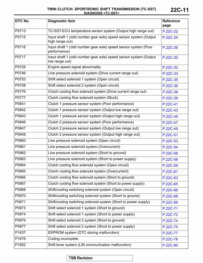
DIAGNOSIS <TC-SST>TWIN CLUTCH- SPORTRONIC SHIFT TRANSMISSION (TC-SST) 22C-11
P0713 TC-SST-ECU temperature sensor system (Output high range out) P.22C-22P0715 Input shaft 1 (odd number gear axle) speed sensor system (Output
high range out)P.22C-24
P0716 Input shaft 1 (odd number gear axle) speed sensor system (Poor performance)
P.22C-26
P0717 Input shaft 1 (odd number gear axle) speed sensor system (Output low range out)
P.22C-30
P0725 Engine speed signal abnormality P.22C-32P0746 Line pressure solenoid system (Drive current range out) P.22C-33P0753 Shift select solenoid 1 system (Open circuit) P.22C-35P0758 Shift select solenoid 2 system (Open circuit) P.22C-36P0776 Clutch cooling flow solenoid system (Drive current range out) P.22C-38P0777 Clutch cooling flow solenoid system (Stuck) P.22C-39P0841 Clutch 1 pressure sensor system (Poor performance) P.22C-41P0842 Clutch 1 pressure sensor system (Output low range out) P.22C-43P0843 Clutch 1 pressure sensor system (Output high range out) P.22C-45P0846 Clutch 2 pressure sensor system (Poor performance) P.22C-47P0847 Clutch 2 pressure sensor system (Output low range out) P.22C-49P0848 Clutch 2 pressure sensor system (Output high range out) P.22C-51P0960 Line pressure solenoid system (Open circuit) P.22C-53P0961 Line pressure solenoid system (Overcurrent) P.22C-54P0962 Line pressure solenoid system (Short to ground) P.22C-56P0963 Line pressure solenoid system (Short to power supply) P.22C-58P0964 Clutch cooling flow solenoid system (Open circuit) P.22C-59P0965 Clutch cooling flow solenoid system (Overcurrent) P.22C-61P0966 Clutch cooling flow solenoid system (Short to ground) P.22C-63P0967 Clutch cooling flow solenoid system (Short to power supply) P.22C-65P0968 Shift/cooling switching solenoid system (Open circuit) P.22C-66P0970 Shift/cooling switching solenoid system (Short to ground) P.22C-68P0971 Shift/cooling switching solenoid system (Short to power supply) P.22C-69P0973 Shift select solenoid 1 system (Short to ground) P.22C-71P0974 Shift select solenoid 1 system (Short to power supply) P.22C-72P0976 Shift select solenoid 2 system (Short to ground) P.22C-74P0977 Shift select solenoid 2 system (Short to power supply) P.22C-75P1637 EEPROM system (DTC storing malfunction) P.22C-77P1676 Coding incomplete P.22C-78P1802 Shift lever system (LIN communication malfunction) P.22C-80
DTC No. Diagnostic item Reference page
TSB Revision

DIAGNOSIS <TC-SST>TWIN CLUTCH- SPORTRONIC SHIFT TRANSMISSION (TC-SST)22C-12
P1803 Shift lever system (CAN or LIN time-out error) P.22C-82P1804 Shift fork position sensor 1 and 2 system (Power supply voltage low
range out)P.22C-84
P1805 Shift fork position sensor 1 and 2 system (Power supply voltage high range out)
P.22C-86
P1806 Shift fork position sensor 3 and 4 system (Power supply voltage low range out)
P.22C-88
P1807 Shift fork position sensor 3 and 4 system (Power supply voltage high range out)
P.22C-90
P1808 TC-SST-ECU temperature, fluid temperature sensor system (Correlation error)
P.22C-92
P180C Clutch pressure cut spool sticking P.22C-93P181B Clutch 1 (Pressure low range out) P.22C-94P181C Clutch 1 (Pressure high range out) P.22C-95P181E Clutch 2 (Pressure low range out) P.22C-99P181F Clutch 2 (Pressure high range out) P.22C-101P1820 Shift fork position sensor 1 system (Voltage low range out) P.22C-105P1821 Shift fork position sensor 1 system (Voltage high range out) P.22C-107P1822 Shift fork position sensor 1 system (Output range out) P.22C-109P1823 Shift fork position sensor 1 system (Neutral) P.22C-111P1824 Shift fork position sensor 1 system (Poor performance) P.22C-113P1825 Shift fork position sensor 2 system (Voltage low range out) P.22C-116P1826 Shift fork position sensor 2 system (Voltage high range out) P.22C-118P1827 Shift fork position sensor 2 system (Output range out) P.22C-120P1828 Shift fork position sensor 2 system (Neutral) P.22C-122P1829 Shift fork position sensor 2 system (Poor performance) P.22C-124P182A Shift fork position sensor 3 system (Voltage low range out) P.22C-127P182B Shift fork position sensor 3 system (Voltage high range out) P.22C-129P182C Shift fork position sensor 3 system (Output range out) P.22C-131P182D Shift fork position sensor 3 system (Neutral) P.22C-133P182E Shift fork position sensor 3 system (Poor performance) P.22C-135P1831 Shift fork position sensor 4 system (Voltage low range out) P.22C-137P1832 Shift fork position sensor 4 system (Voltage high range out) P.22C-139P1833 Shift fork position sensor 4 system (Output range out) P.22C-141P1834 Shift fork position sensor 4 system (Neutral) P.22C-143P1835 Shift fork position sensor 4 system (Poor performance) P.22C-145P1836 Shift fork 1 malfunction P.22C-148P183D Shift fork 2 malfunction P.22C-156
DTC No. Diagnostic item Reference page
TSB Revision

DIAGNOSIS <TC-SST>TWIN CLUTCH- SPORTRONIC SHIFT TRANSMISSION (TC-SST) 22C-13
P1844 Shift fork 3 malfunction P.22C-164P184B Shift fork 4 malfunction P.22C-171P1852 Shift fork 1 or 2 opposite direction movement P.22C-179P1855 Shift fork 3 or 4 opposite direction movement P.22C-182P1857 Odd number gear axle interlock P.22C-185P1858 Even number gear axle interlock P.22C-187P1859 Disengagement too late with clutch 1 P.22C-189P185A Engagement too late with clutch 1 P.22C-190P185B Disengagement too late with clutch 2 P.22C-191P185C Engagement too late with clutch 2 P.22C-193P185D Clutch open not possible P.22C-193P1862 High side 1 system (Overcurrent) P.22C-195P1863 High side 1 system (Open circuit) P.22C-197P1864 High side 1 system (Short to power supply) P.22C-199P1866 High side 2 system (Overcurrent) P.22C-201P1867 High side 2 system (Open circuit) P.22C-203P1868 High side 2 system (Short to power supply) P.22C-205P186A High side 3 system (Overcurrent) P.22C-207P186B High side 3 system (Open circuit) P.22C-209P186C High side 3 system (Short to power supply) P.22C-211P186D High side 1 system (Voltage low range out) P.22C-213P186E High side 2 system (Voltage low range out) P.22C-215P186F High side 3 system (Voltage low range out) P.22C-217P1870 Engine torque signal abnormality P.22C-219P1871 APS system (Signal abnormality) P.22C-221P1872 Between shift lever and TC-SST system (Q-A function abnormality) P.22C-223P1873 Clutch 1 system (Pressure abnormality) P.22C-225P1874 Clutch 2 system (Pressure abnormality) P.22C-225P1875 Damper speed sensor system (Poor performance) P.22C-226P1876 Gear block 1st P.22C-229P1877 Gear block 2nd P.22C-230P1878 Gear block 3rd P.22C-232P1879 Gear block 4th P.22C-233P187A Gear block 5th P.22C-235P187B Gear block 6th P.22C-236P187C Gear block reverse P.22C-238
DTC No. Diagnostic item Reference page
TSB Revision

DIAGNOSIS <TC-SST>TWIN CLUTCH- SPORTRONIC SHIFT TRANSMISSION (TC-SST)22C-14
P1880 EOL Mode Active P.22C-239P1881 Twin clutch SST control mode switch system (Malfunction) P.22C-240P2718 Clutch/shift pressure solenoid 1 system (Open circuit) P.22C-241P2719 Clutch/shift pressure solenoid 1 system (Overcurrent) P.22C-243P2720 Clutch/shift pressure solenoid 1 system (Short to ground) P.22C-245P2721 Clutch/shift pressure solenoid 1 system (Short to power supply) P.22C-247P2727 Clutch/shift pressure solenoid 2 system (Open circuit) P.22C-249P2728 Clutch/shift pressure solenoid 2 system (Overcurrent) P.22C-251P2729 Clutch/shift pressure solenoid 2 system (Short to ground) P.22C-253P2730 Clutch/shift pressure solenoid 2 system (Short to power supply) P.22C-255P2733 Clutch/shift switching solenoid 1, spool stuck P.22C-257P2736 Clutch/shift switching solenoid 1 system (Open circuit) P.22C-259P2738 Clutch/shift switching solenoid 1 system (Short to ground) P.22C-261P2739 Clutch/shift switching solenoid 1 system (Short to power supply) P.22C-262P2741 Fluid temperature sensor system (Gradient error) P.22C-264P2742 Fluid temperature sensor system (Output low range out) P.22C-266P2743 Fluid temperature sensor system (Output high range out) P.22C-268P2766 Input shaft 2 (even number gear axle) speed sensor system (Poor
performance)P.22C-270
P2809 Clutch/shift switching solenoid 2, spool stuck P.22C-274P2812 Clutch/shift switching solenoid 2 system (Open circuit) P.22C-276P2814 Clutch/shift switching solenoid 2 system (Short to ground) P.22C-278P2815 Clutch/shift switching solenoid 2 system (Short to power supply) P.22C-280U0001 Bus off P.22C-282U0100 Engine time-out error P.22C-284U0103 Shift lever time-out error P.22C-286U0121 ASC time-out error P.22C-287U0136 AWC time-out error P.22C-287U0141 ETACS time-out error P.22C-288
DTC No. Diagnostic item Reference page
TSB Revision

DIAGNOSIS <TC-SST>TWIN CLUTCH- SPORTRONIC SHIFT TRANSMISSION (TC-SST) 22C-15
SYMPTOM CHARTM1225005200035
CAUTIONDuring diagnosis, a DTC associated with other system may be set when the ignition switch is turned ON with connector(s) disconnected. On completion, confirm all systems for diagnostic trouble code(s). If diagnostic trouble code(s) are set, erase them all.
DIAGNOSTIC TROUBLE CODE PROCEDURES
DTC P0630: VIN not Recorded
CAUTION• If there is any problem in the CAN bus lines,
an incorrect diagnostic trouble code may be set. Prior to this diagnosis, diagnose the CAN bus lines.
• Whenever the ECU is replaced, ensure that the CAN bus lines are normal.
.
DIAGNOSTIC FUNCTIONTC-SST-ECU checks that the chassis number is nor-mal.
(TC-SST-ECU receives chassis number information from the engine control module via CAN, and write to TC-SST-ECU.).
DESCRIPTIONS OF MONITOR METHODSThe chassis number is determined to be written abnormally..
PROBABLE CAUSES• The CAN bus line is defective.• Malfunction of engine control module• Malfunction of TC-SST-ECU
DIAGNOSTIC PROCEDURE
STEP 1. Scan tool CAN bus diagnosticsUsing scan tool MB991958, diagnose the CAN bus lines.Q: Is the check result normal?
YES : Go to Step 2.NO : Repair the CAN bus lines. (Refer to GROUP 54C −
Troubleshooting P.54C-14.) After repairing the CAN bus line, go to Step 2.
STEP 2. Scan tool diagnostic trouble codeCheck the engine diagnostic trouble code. (Refer to GROUP 13A − Troubleshooting P.13A-44.)Q: Is the DTC set?
YES : Perform the relevant troubleshooting.NO : Go to Step 3.
Symptom Inspection procedure No.
Reference page
The scan tool cannot communicate with TC-SST-ECU. 1 P.22C-289The driving mode cannot be changed. 2 P.22C-290Speed change with the paddle shift is impossible. 3 P.22C-292TC-SST-ECU power supply circuit malfunction 4 P.22C-295
TSB Revision

DIAGNOSIS <TC-SST>TWIN CLUTCH- SPORTRONIC SHIFT TRANSMISSION (TC-SST)22C-16
STEP 3. Check whether the DTC is reset.Q: Is DTC No. P0630 set?
YES : Replace the TC-SST assembly. (Refer to P.22C-341.)NO : Intermittent malfunction. (Refer to GROUP 00 − How
to Cope with Intermittent Malfunction P.00-15.)
DTC P0701: EEPROM System (Malfunction)
CAUTION• If there is any problem in the CAN bus lines,
an incorrect diagnostic trouble code may be set. Prior to this diagnosis, diagnose the CAN bus lines.
• Whenever the ECU is replaced, ensure that the CAN bus lines are normal.
.
DIAGNOSTIC FUNCTIONTC-SST-ECU checks that the EEPROM and RAM in the TC-SST-ECU is normal..
DESCRIPTIONS OF MONITOR METHODSThe EEPROM writing data is determined to be abnormal..
PROBABLE CAUSES• Malfunction of TC-SST-ECU
DIAGNOSTIC PROCEDURE
STEP 1. Scan tool CAN bus diagnosticsUsing scan tool MB991958, diagnose the CAN bus lines.Q: Is the check result normal?
YES : Go to Step 2.NO : Repair the CAN bus lines. (Refer to GROUP 54C −
Troubleshooting P.54C-14.) After repairing the CAN bus line, go to Step 2.
STEP 2. Check whether the DTC is reset.Q: Is DTC No. P0701 set?
YES : Replace the TC-SST assembly. (Refer to P.22C-341.)NO : Intermittent malfunction. (Refer to GROUP 00 − How
to Cope with Intermittent Malfunction P.00-15.)
DTC P0702: Internal control module, monitoring processor system (Malfunction)
CAUTION• If there is any problem in the CAN bus lines,
an incorrect diagnostic trouble code may be set. Prior to this diagnosis, diagnose the CAN bus lines.
• Whenever the ECU is replaced, ensure that the CAN bus lines are normal.
.
DIAGNOSTIC FUNCTIONTC-SST-ECU checks that the internal module and monitoring processor are normal..
DESCRIPTIONS OF MONITOR METHODSThe internal module and monitoring processor are determined to be abnormal..
TSB Revision

DIAGNOSIS <TC-SST>TWIN CLUTCH- SPORTRONIC SHIFT TRANSMISSION (TC-SST) 22C-17
MONITOR EXECUTION• Continuous
.
MONITOR EXECUTION CONDITIONS (OTHER MONITOR AND SENSOR)Other Monitor (There is no temporary DTC stored
in memory for the item monitored below)• Not applicable
Sensor (The sensor below is determined to be normal)
• Not applicable.
LOGIC FLOW CHARTS (Monitor Sequence)
.
DTC SET CONDITIONSCheck Conditions• Voltage of battery: 8 V or more.• Voltage of battery: 16.5 V or less.
JUDGMENT CRITERIA• Internal module, Monitoring processor: fault.
.
OBD-II DRIVE CYCLE PATTERNThe internal module and monitoring processor are normal..
PROBABLE CAUSES• Malfunction of TC-SST-ECU
DIAGNOSTIC PROCEDURE
STEP 1. Scan tool CAN bus diagnosticsUsing scan tool MB991958, diagnose the CAN bus lines.Q: Is the check result normal?
YES : Go to Step 2.NO : Repair the CAN bus lines. (Refer to GROUP 54C −
Troubleshooting P.54C-14.) After repairing the CAN bus line, go to Step 2.
AC710451
START
No
Internal module, monitoringprocessor is failed
Yes
Yes
No
GoodMalfunction
END
Monitoring condition met
TSB Revision

DIAGNOSIS <TC-SST>TWIN CLUTCH- SPORTRONIC SHIFT TRANSMISSION (TC-SST)22C-18
STEP 2. Check whether the DTC is reset.Q: Is DTC No. P0702 set?
YES : Replace the TC-SST assembly. (Refer to P.22C-341.)NO : Intermittent malfunction. (Refer to GROUP 00 − How
to Cope with Intermittent Malfunction P.00-15.)
DTC P0711: TC-SST-ECU temperature sensor system (Gradient error)
CAUTION• If there is any problem in the CAN bus lines,
an incorrect diagnostic trouble code may be set. Prior to this diagnosis, diagnose the CAN bus lines.
• Whenever the ECU is replaced, ensure that the CAN bus lines are normal.
.
DIAGNOSTIC FUNCTIONTC-SST-ECU checks that the output gradient of the ECU temperature sensor is normal..
DESCRIPTIONS OF MONITOR METHODSThe ECU temperature change is determined to be abnormal..
MONITOR EXECUTION• Continuous
.
MONITOR EXECUTION CONDITIONS (OTHER MONITOR AND SENSOR)Other Monitor (There is no temporary DTC stored
in memory for the item monitored below)• P0712: TC-SST-ECU temperature sensor system
(Output low range out)• P0713: TC-SST-ECU temperature sensor system
(Output high range out)• P1808: TC-SST-ECU temperature, fluid tempera-
ture sensor system (Correlation error)
Sensor (The sensor below is determined to be normal)
• Not applicable.
TSB Revision

DIAGNOSIS <TC-SST>TWIN CLUTCH- SPORTRONIC SHIFT TRANSMISSION (TC-SST) 22C-19
LOGIC FLOW CHARTS (Monitor Sequence)
.
DTC SET CONDITIONSCheck Conditions• Voltage of battery: 8 V or more.• Voltage of battery: 16.5 V or less.
JUDGMENT CRITERIA• Fluid temperature change while 80 millisecond:
10° C (18° F) or more, or fluid temperature change while 80 millisecond: −10° C (−18° F) or more. (400 millisecond)
.
OBD-II DRIVE CYCLE PATTERNThe absolute value of the temperature rise or drop at every 80 milliseconds remains 10° C (18° F) or less for 400 milliseconds..
PROBABLE CAUSES• Malfunction of TC-SST-ECU
AC710592
START
No
Fluid temperature changewhile 80 msec > 10 ˚C (18 ˚F)
Yes
Yes
No
GoodMalfunction
END
Monitoring condition met
No
Continuous failurefor 400 msec
Yes
No
Fluid temperature changewhile 80 msec > -10 ˚C (-18 ˚F)
TSB Revision

DIAGNOSIS <TC-SST>TWIN CLUTCH- SPORTRONIC SHIFT TRANSMISSION (TC-SST)22C-20
DIAGNOSTIC PROCEDURE
STEP 1. Scan tool CAN bus diagnosticsUsing scan tool MB991958, diagnose the CAN bus lines.Q: Is the check result normal?
YES : Go to Step 2.NO : Repair the CAN bus lines. (Refer to GROUP 54C −
Troubleshooting P.54C-14.) After repairing the CAN bus line, go to Step 2.
STEP 2. Check whether the DTC is reset.Q: Is DTC No. P0711 set?
YES : Replace the TC-SST assembly. (Refer to P.22C-341.)NO : Intermittent malfunction. (Refer to GROUP 00 − How
to Cope with Intermittent Malfunction P.00-15.)
DTC P0712: TC-SST-ECU temperature sensor system (Output low range out)
CAUTION• If there is any problem in the CAN bus lines,
an incorrect diagnostic trouble code may be set. Prior to this diagnosis, diagnose the CAN bus lines.
• Whenever the ECU is replaced, ensure that the CAN bus lines are normal.
.
DIAGNOSTIC FUNCTIONTC-SST-ECU checks that the output of the ECU tem-perature sensor is normal..
DESCRIPTIONS OF MONITOR METHODSThe output of the ECU temperature is determined to be too low..
MONITOR EXECUTION• Continuous
.
MONITOR EXECUTION CONDITIONS (OTHER MONITOR AND SENSOR)Other Monitor (There is no temporary DTC stored
in memory for the item monitored below)• P0711: TC-SST-ECU temperature sensor system
(Gradient error)• P0713: TC-SST-ECU temperature sensor system
(Output high range out)• P1808: TC-SST-ECU temperature, fluid tempera-
ture sensor system (Correlation error)
Sensor (The sensor below is determined to be normal)
• Not applicable.
TSB Revision

DIAGNOSIS <TC-SST>TWIN CLUTCH- SPORTRONIC SHIFT TRANSMISSION (TC-SST) 22C-21
LOGIC FLOW CHARTS (Monitor Sequence)
.
DTC SET CONDITIONSCheck Conditions• Voltage of battery: 8 V or more.• Voltage of battery: 16.5 V or less.
JUDGMENT CRITERIA• Fluid temperature: −50° C (−58° F) or less. (400
millisecond)
.
OBD-II DRIVE CYCLE PATTERNThe TC-SST-ECU temperature remains −50° C (−58° F) or more for 400 milliseconds..
PROBABLE CAUSES• Malfunction of TC-SST-ECU
DIAGNOSTIC PROCEDURE
STEP 1. Scan tool CAN bus diagnosticsUsing scan tool MB991958, diagnose the CAN bus lines.Q: Is the check result normal?
YES : Go to Step 2.NO : Repair the CAN bus lines. (Refer to GROUP 54C −
Troubleshooting P.54C-14.) After repairing the CAN bus line, go to Step 2.
AC710593
START
No
Yes
Yes
GoodMalfunction
END
Monitoring condition met
No
Continuous failurefor 400 msec
No
Fluid temperature < -50 ˚C (-58 ˚F)
Yes
TSB Revision

DIAGNOSIS <TC-SST>TWIN CLUTCH- SPORTRONIC SHIFT TRANSMISSION (TC-SST)22C-22
STEP 2. Check whether the DTC is reset.Q: Is DTC No. P0712 set?
YES : Replace the TC-SST assembly. (Refer to P.22C-341.)NO : Intermittent malfunction. (Refer to GROUP 00 − How
to Cope with Intermittent Malfunction P.00-15.)
DTC P0713: TC-SST-ECU temperature sensor system (Output high range out)
CAUTION• If there is any problem in the CAN bus lines,
an incorrect diagnostic trouble code may be set. Prior to this diagnosis, diagnose the CAN bus lines.
• Whenever the ECU is replaced, ensure that the CAN bus lines are normal.
.
DIAGNOSTIC FUNCTIONTC-SST-ECU checks that the output of the ECU tem-perature sensor is normal..
DESCRIPTIONS OF MONITOR METHODSThe output of the ECU temperature is determined to be too high..
MONITOR EXECUTION• Continuous
.
MONITOR EXECUTION CONDITIONS (OTHER MONITOR AND SENSOR)Other Monitor (There is no temporary DTC stored
in memory for the item monitored below)• P0711: TC-SST-ECU temperature sensor system
(Gradient error)• P0712: TC-SST-ECU temperature sensor system
(Output low range out)• P1808: TC-SST-ECU temperature, fluid tempera-
ture sensor system (Correlation error)
Sensor (The sensor below is determined to be normal)
• Not applicable.
TSB Revision

DIAGNOSIS <TC-SST>TWIN CLUTCH- SPORTRONIC SHIFT TRANSMISSION (TC-SST) 22C-23
LOGIC FLOW CHARTS (Monitor Sequence)
.
DTC SET CONDITIONSCheck Conditions• Voltage of battery: 8 V or more.• Voltage of battery: 16.5 V or less.
JUDGMENT CRITERIA• Fluid temperature: 150° C (302° F) or more. (400
millisecond)
.
OBD-II DRIVE CYCLE PATTERNThe TC-SST-ECU temperature remains 150° C (302° F) or less for 400 milliseconds..
PROBABLE CAUSES• Malfunction of TC-SST-ECU
DIAGNOSTIC PROCEDURE
STEP 1. Scan tool CAN bus diagnosticsUsing scan tool MB991958, diagnose the CAN bus lines.Q: Is the check result normal?
YES : Go to Step 2.NO : Repair the CAN bus lines. (Refer to GROUP 54C −
Troubleshooting P.54C-14.) After repairing the CAN bus line, go to Step 2.
AC710594
START
No
Yes
Yes
GoodMalfunction
END
Vehicle condition met
No
Continuous failurefor 400 msec
No
Fluid temperature > 150 ˚C (302 ˚F)
Yes
TSB Revision

DIAGNOSIS <TC-SST>TWIN CLUTCH- SPORTRONIC SHIFT TRANSMISSION (TC-SST)22C-24
STEP 2. Check whether the DTC is reset.Q: Is DTC No. P0713 set?
YES : Replace the TC-SST assembly. (Refer to P.22C-341.)NO : Intermittent malfunction. (Refer to GROUP 00 − How
to Cope with Intermittent Malfunction P.00-15.)
DTC P0715: Input shaft 1 (odd number gear axle) speed sensor system (Output high range out)
CAUTION• If there is any problem in the CAN bus lines,
an incorrect diagnostic trouble code may be set. Prior to this diagnosis, diagnose the CAN bus lines.
• Whenever the ECU is replaced, ensure that the CAN bus lines are normal.
.
DIAGNOSTIC FUNCTIONTC-SST-ECU checks that the input shaft 1 (odd num-ber gear axle) speed sensor is normal..
DESCRIPTIONS OF MONITOR METHODSThe output of the input shaft 1 (odd number gear axle) is determined to be too high..
MONITOR EXECUTION• Continuous
.
MONITOR EXECUTION CONDITIONS (OTHER MONITOR AND SENSOR)Other Monitor (There is no temporary DTC stored
in memory for the item monitored below)• P0716: Input shaft 1 (odd number gear axle)
speed sensor system (Poor performance)• P0717: Input shaft 1 (odd number gear axle)
speed sensor system (Output low range out)• P2766: Input shaft 2 (even number gear axle)
speed sensor system (Poor performance)
Sensor (The sensor below is determined to be normal)
• Input shaft 2 (even number gear axle) speed sen-sor
.
TSB Revision

DIAGNOSIS <TC-SST>TWIN CLUTCH- SPORTRONIC SHIFT TRANSMISSION (TC-SST) 22C-25
LOGIC FLOW CHARTS (Monitor Sequence)
.
DTC SET CONDITIONSCheck Conditions• Voltage of battery: 8 V or more.• Voltage of battery: 16.5 V or less.• Time after engine start: 400 millisecond or more.
JUDGMENT CRITERIA• Sensor current: 17 mA or more. (500 millisecond)
.
OBD-II DRIVE CYCLE PATTERNThe sensor current remains 17 mA or less for 500 milliseconds..
PROBABLE CAUSES• Malfunction of TC-SST-ECU
DIAGNOSTIC PROCEDURE
STEP 1. Scan tool CAN bus diagnosticsUsing scan tool MB991958, diagnose the CAN bus lines.Q: Is the check result normal?
YES : Go to Step 2.NO : Repair the CAN bus lines. (Refer to GROUP 54C −
Troubleshooting P.54C-14.) After repairing the CAN bus line, go to Step 2.
Sensor current < 4 mA
AC710596
START
No
Yes
Yes
No
GoodMalfunction
END
Monitoring condition met
No
Continuous failurefor 500 msec
Yes
No
Sensor current > 17 mA
TSB Revision

DIAGNOSIS <TC-SST>TWIN CLUTCH- SPORTRONIC SHIFT TRANSMISSION (TC-SST)22C-26
STEP 2. Check whether the DTC is reset.Q: Is DTC No. P0715 set?
YES : Replace the TC-SST assembly. (Refer to P.22C-341.)NO : Intermittent malfunction. (Refer to GROUP 00 − How
to Cope with Intermittent Malfunction P.00-15.)
DTC P0716: Input shaft 1 (odd number gear axle) speed sensor system (Poor performance)
CAUTION• If there is any problem in the CAN bus lines,
an incorrect diagnostic trouble code may be set. Prior to this diagnosis, diagnose the CAN bus lines.
• Whenever the ECU is replaced, ensure that the CAN bus lines are normal.
.
DIAGNOSTIC FUNCTIONTC-SST-ECU checks that the input shaft 1 (odd num-ber gear axle) speed sensor is normal..
DESCRIPTIONS OF MONITOR METHODSThe rotation speed of the input shaft 1 (odd number gear axle) is determined to be abnormal..
MONITOR EXECUTION• Continuous
.
MONITOR EXECUTION CONDITIONS (OTHER MONITOR AND SENSOR)Other Monitor (There is no temporary DTC stored
in memory for the item monitored below)• P0715: Input shaft 1 (odd number gear axle)
speed sensor system (Output high range out)• P0717: Input shaft 1 (odd number gear axle)
speed sensor system (Output low range out)• P2766: Input shaft 2 (even number gear axle)
speed sensor system (Poor performance)
Sensor (The sensor below is determined to be normal)
• Input shaft 2 (even number gear axle) speed sen-sor
.
TSB Revision

DIAGNOSIS <TC-SST>TWIN CLUTCH- SPORTRONIC SHIFT TRANSMISSION (TC-SST) 22C-27
LOGIC FLOW CHARTS (Monitor Sequence) <Rationality>
.
AC710597
START
No
Yes
Yes
No
GoodMalfunction
END
Monitoring condition met
Continuous failurefor 500 msec
Yes
No
Failure condition 1
Failure condition 2No
TSB Revision

DIAGNOSIS <TC-SST>TWIN CLUTCH- SPORTRONIC SHIFT TRANSMISSION (TC-SST)22C-28
LOGIC FLOW CHARTS (Monitor Sequence) <Rationality (Failure condition 1)>
.
LOGIC FLOW CHARTS (Monitor Sequence) <Rationality (Failure condition 2)>
.
DTC SET CONDITIONSCheck Conditions <Rationality>• Voltage of battery: 8 V or more.
• Voltage of battery: 16.5 V or less.• Input shaft [odd] gear: engaged.• Input shaft [even] gear: engaged.
AC710598
START
No
Yes
Malfunction
No
Yes
|(Input shaft speed [odd] /total gear ratio [odd]) - (input shaft speed [even] /total gear ratio [even])| > 100 r/min
|(Input shaft speed*1 / total gear ratio [odd]) -output shaft speed| > 300 r/min
Failure condition 2
*1 : In case of input speed sensor A monitor, this is speed of input shaft (odd). In case of input speed sensor B monitor, this is speed of input shaft (even).
AC710599
No
Yes
GoodMalfunction
Input shaft speed [odd]< 1 r/min
No
Yes
Input shaft speed [even]> 50 r/min
No
Yes
GoodMalfunction
Input shaft speed [odd]> 50 r/min
No
Yes
Input shaft speed [even]< 1 r/min
*2 *3
*2 :In case of input speed sensor A monitor *3 :In case of input speed sensor B monitor
TSB Revision

DIAGNOSIS <TC-SST>TWIN CLUTCH- SPORTRONIC SHIFT TRANSMISSION (TC-SST) 22C-29
JUDGMENT CRITERIA <Rationality>• Failure condition 1 or failure condition 2 (Refer to
Logic Flow Charts (Monitor Sequence) <Rational-ity>). (500 millisecond)
.
OBD-II DRIVE CYCLE PATTERN <RATIONALITY>Each value of failure condition 1 or failure condition 2 (Logic Flow Charts (Monitor Sequence) <Rational-ity>) returns to the normal value and remains in the state for 500 milliseconds..
LOGIC FLOW CHARTS (Monitor Sequence) <Rationality - plausibility failure>
.
AC710601
No
Yes
Malfunction
No
Yes
Monitoring condition met
No
Yes
Yes
Engine speed signalstatus = not SNA
Continuous failurefor 250 msec
Input shaft speed*1
> 12,800 r/min
START
END
Yes
|Input shaft speed*1| > (min(max(engine speed, input shaft target speed [current gear]*1,input shaft target speed [target gear]*1) + 3,000 r/min,12,800 r/min)
Good
No
No
*1 :In case of input shaft 1 (odd) speed sensor monitor, this is speed of input shaft (odd). In case of input shaft 2 (even) speed sensor monitor, this is speed of input shaft (even).
TSB Revision

DIAGNOSIS <TC-SST>TWIN CLUTCH- SPORTRONIC SHIFT TRANSMISSION (TC-SST)22C-30
Check Conditions <Rationality plausibility fail-ure>
• Voltage of battery: 8 V or more.• Voltage of battery: 16.5 V or less.
JUDGMENT CRITERIA <Rationality plausibility failure>
• Input shaft 1 (odd) speed: Refer to Logic Flow Charts (Monitor Sequence) <Rationality plausibil-ity failure>. (250 millisecond)
.
OBD-II DRIVE CYCLE PATTERN <RATIONALITY PLAUSIBILITY FAILURE>The value of the Logic Flow Charts (Monitor Sequence) <Rationality plausibility failure> returns to the normal value and remains in the state for 250 mil-liseconds..
PROBABLE CAUSES• Malfunction of TC-SST-ECU
DIAGNOSTIC PROCEDURE
STEP 1. Scan tool CAN bus diagnosticsUsing scan tool MB991958, diagnose the CAN bus lines.Q: Is the check result normal?
YES : Go to Step 2.NO : Repair the CAN bus lines. (Refer to GROUP 54C −
Troubleshooting P.54C-14.) After repairing the CAN bus line, go to Step 2.
STEP 2. Check whether the DTC is reset.Q: Is DTC No. P0716 set?
YES : Replace the TC-SST assembly. (Refer to P.22C-341.)NO : Intermittent malfunction. (Refer to GROUP 00 − How
to Cope with Intermittent Malfunction P.00-15.)
DTC P0717: Input shaft 1 (odd number gear axle) speed sensor system (Output current low range out)
CAUTION• If there is any problem in the CAN bus lines,
an incorrect diagnostic trouble code may be set. Prior to this diagnosis, diagnose the CAN bus lines.
• Whenever the ECU is replaced, ensure that the CAN bus lines are normal.
.
DIAGNOSTIC FUNCTIONTC-SST-ECU checks that the input shaft 1 (odd num-ber gear axle) speed sensor is normal..
DESCRIPTIONS OF MONITOR METHODSThe output of the input shaft 1 (odd number gear axle) speed sensor is determined to be too low..
MONITOR EXECUTION• Continuous
.
MONITOR EXECUTION CONDITIONS (OTHER MONITOR AND SENSOR)Other Monitor (There is no temporary DTC stored
in memory for the item monitored below)• P0715: Input shaft 1 (odd number gear axle)
speed sensor system (Output high range out)• P0716: Input shaft 1 (odd number gear axle)
speed sensor system (Poor performance)• P2766: Input shaft 2 (even number gear axle)
speed sensor system (Poor performance)
Sensor (The sensor below is determined to be normal)
• Input shaft 2 (even number gear axle) speed sen-sor
.
TSB Revision

DIAGNOSIS <TC-SST>TWIN CLUTCH- SPORTRONIC SHIFT TRANSMISSION (TC-SST) 22C-31
LOGIC FLOW CHARTS (Monitor Sequence)
.
DTC SET CONDITIONSCheck Conditions• Voltage of battery: 8 V or more.• Voltage of battery: 16.5 V or less.• Time after engine start: 400 millisecond or more.
JUDGMENT CRITERIA• Sensor current: 4 mA or less. (500 millisecond)
.
OBD-II DRIVE CYCLE PATTERNThe sensor current remains 4 mA or more for 500 milliseconds..
PROBABLE CAUSES• Malfunction of TC-SST-ECU
DIAGNOSTIC PROCEDURE
STEP 1. Scan tool CAN bus diagnosticsUsing scan tool MB991958, diagnose the CAN bus lines.Q: Is the check result normal?
YES : Go to Step 2.NO : Repair the CAN bus lines. (Refer to GROUP 54C −
Troubleshooting P.54C-14.) After repairing the CAN bus line, go to Step 2.
Sensor current < 4 mA
AC710596
START
No
Yes
Yes
No
GoodMalfunction
END
Monitoring condition met
No
Continuous failurefor 500 msec
Yes
No
Sensor current > 17 mA
TSB Revision

DIAGNOSIS <TC-SST>TWIN CLUTCH- SPORTRONIC SHIFT TRANSMISSION (TC-SST)22C-32
STEP 2. Check whether the DTC is reset.Q: Is DTC No. P0717 set?
YES : Replace the TC-SST assembly. (Refer to P.22C-341.)NO : Intermittent malfunction. (Refer to GROUP 00 − How
to Cope with Intermittent Malfunction P.00-15.)
DTC P0725: Engine speed signal abnormality
CAUTION• If there is any problem in the CAN bus lines,
an incorrect diagnostic trouble code may be set. Prior to this diagnosis, diagnose the CAN bus lines.
• Whenever the ECU is replaced, ensure that the CAN bus lines are normal.
.
DIAGNOSTIC FUNCTIONTC-SST-ECU receives the periodic communication data from the engine control module via the CAN bus lines, and checks the data for abnormality.
.
DESCRIPTIONS OF MONITOR METHODSThe engine speed signal from the engine control module is determined to be abnormal..
PROBABLE CAUSES• The CAN bus line is defective.• Malfunction of crankshaft position sensor• Malfunction of engine control module• Malfunction of TC-SST-ECU
DIAGNOSTIC PROCEDURE
STEP 1. Scan tool CAN bus diagnosticsUsing the scan tool, diagnose the CAN bus lines.Q: Is the check result normal?
YES : Go to Step 2.NO : Repair the CAN bus lines. (Refer to GROUP 54C −
Troubleshooting P.54C-14.) After repairing the CAN bus line, go to Step 2.
STEP 2. Scan tool diagnostic trouble codeCheck the engine diagnostic trouble code. (Refer to GROUP 13A − Troubleshooting P.13A-44.)Q: Is the DTC set?
YES : Perform the relevant troubleshooting.NO : Go to Step 3.
STEP 3. Check whether the DTC is reset.Q: Is DTC No. P0725 set?
YES : Replace the TC-SST assembly. (Refer to P.22C-341.)NO : Intermittent malfunction. (Refer to GROUP 00 − How
to Cope with Intermittent Malfunction P.00-15.)
TSB Revision

DIAGNOSIS <TC-SST>TWIN CLUTCH- SPORTRONIC SHIFT TRANSMISSION (TC-SST) 22C-33
DTC P0746: Line Pressure Solenoid System (Drive current range out)
CAUTION• If there is any problem in the CAN bus lines,
an incorrect diagnostic trouble code may be set. Prior to this diagnosis, diagnose the CAN bus lines.
• Whenever the ECU is replaced, ensure that the CAN bus lines are normal.
.
DIAGNOSTIC FUNCTIONTC-SST-ECU checks that the line pressure solenoid is normal..
DESCRIPTIONS OF MONITOR METHODSThe difference between the actual current of the line pressure solenoid and target current is large..
MONITOR EXECUTION• Continuous
.
MONITOR EXECUTION CONDITIONS (OTHER MONITOR AND SENSOR)Other Monitor (There is no temporary DTC stored
in memory for the item monitored below)• P0960: Line pressure solenoid system (Open cir-
cuit)• P0961: Line pressure solenoid system (Overvolt-
age)• P0962: Line pressure solenoid system (Short to
ground)• P0963: Line pressure solenoid system (Short to
power supply)
Sensor (The sensor below is determined to be normal)
• Not applicable.
LOGIC FLOW CHARTS (Monitor Sequence) <Rationality - high>
.
DTC SET CONDITIONSCheck Conditions <Rationality-high>• Voltage of battery: 8 V or more.
• Voltage of battery: 16.5 V or less.
JUDGMENT CRITERIA <Rationality-high>• Calculated current (actual current − target cur-
rent): 500 mA or more. (1 second)
AC710625
START
No
Yes
Yes
GoodMalfunction
END
Monitoring condition met
No
Continuous failurefor 1 sec
No
Yes
Calculated current > 500 mA
TSB Revision

DIAGNOSIS <TC-SST>TWIN CLUTCH- SPORTRONIC SHIFT TRANSMISSION (TC-SST)22C-34
.
OBD-II DRIVE CYCLE PATTERN <RATIONALITY-HIGH>The value of the calculated current (actual current − target current) remains 500 mA or less for 1 second.
.
LOGIC FLOW CHARTS (Monitor Sequence) <Rationality - low>
.
DTC SET CONDITIONSCheck Conditions <Rationality-low>• Voltage of battery: 8 V or more.• Voltage of battery: 16.5 V or less.
JUDGMENT CRITERIA <Rationality-low>• Calculated current (target current − actual cur-
rent): 500 mA or more. (12 seconds)
.
OBD-II DRIVE CYCLE PATTERN <RATIONALITY-LOW>The value of the calculated current (target current − actual current) remains 500 mA or less for 12 sec-onds..
PROBABLE CAUSES• Malfunction of TC-SST-ECU
DIAGNOSTIC PROCEDURE
STEP 1. Scan tool CAN bus diagnosticsUsing scan tool MB991958, diagnose the CAN bus lines.Q: Is the check result normal?
YES : Go to Step 2.NO : Repair the CAN bus lines. (Refer to GROUP 54C −
Troubleshooting P.54C-14.) After repairing the CAN bus line, go to Step 2.
AC710626
START
No
Yes
Yes
GoodMalfunction
END
Monitoring condition met
No
Continuous failurefor 12 sec
No
Yes
Calculated current > 500 mA
TSB Revision

DIAGNOSIS <TC-SST>TWIN CLUTCH- SPORTRONIC SHIFT TRANSMISSION (TC-SST) 22C-35
STEP 2. Check whether the DTC is reset.Q: Is DTC No. P0746 set?
YES : Replace the TC-SST assembly. (Refer to P.22C-341.)NO : Intermittent malfunction. (Refer to GROUP 00 − How
to Cope with Intermittent Malfunction P.00-15.)
DTC P0753: Shift Select Solenoid 1 System (Open circuit)
CAUTION• If there is any problem in the CAN bus lines,
an incorrect diagnostic trouble code may be set. Prior to this diagnosis, diagnose the CAN bus lines.
• Whenever the ECU is replaced, ensure that the CAN bus lines are normal.
.
DIAGNOSTIC FUNCTIONTC-SST-ECU checks that the shift select solenoid 1 circuit is normal..
DESCRIPTIONS OF MONITOR METHODSThe shift select solenoid 1 circuit is determined to be open.
.
MONITOR EXECUTION• Continuous
.
MONITOR EXECUTION CONDITIONS (OTHER MONITOR AND SENSOR)Other Monitor (There is no temporary DTC stored
in memory for the item monitored below)• Not applicable
Sensor (The sensor below is determined to be normal)
• Not applicable.
LOGIC FLOW CHARTS (Monitor Sequence)
AC710622
START
No
Yes
Yes
GoodMalfunction
END
Monitoring condition met
No
Continuous failurefor 1 sec
No
Yes
FET* output > 1 V
*FET : Field Effect Transistor
TSB Revision

DIAGNOSIS <TC-SST>TWIN CLUTCH- SPORTRONIC SHIFT TRANSMISSION (TC-SST)22C-36
.
DTC SET CONDITIONSCheck Conditions• Voltage of battery: 8 V or more.• Voltage of battery: 16.5 V or less.
JUDGMENT CRITERIA• FET (Field Effect Transistor) output: 1 V or more.
(1 second)
.
OBD-II DRIVE CYCLE PATTERNThe FET channel output remains 1 V or less for 1 second..
PROBABLE CAUSES• Malfunction of TC-SST-ECU
DIAGNOSTIC PROCEDURE
STEP 1. Scan tool CAN bus diagnosticsUsing scan tool MB991958, diagnose the CAN bus lines.Q: Is the check result normal?
YES : Go to Step 2.NO : Repair the CAN bus lines. (Refer to GROUP 54C −
Troubleshooting P.54C-14.) After repairing the CAN bus line, go to Step 2.
STEP 2. Check whether the DTC is reset.Q: Is DTC No. P0753 set?
YES : Replace the TC-SST assembly. (Refer to P.22C-341.)NO : Intermittent malfunction. (Refer to GROUP 00 − How
to Cope with Intermittent Malfunction P.00-15.)
DTC P0758: Shift Select Solenoid 2 System (Open circuit)
CAUTION• If there is any problem in the CAN bus lines,
an incorrect diagnostic trouble code may be set. Prior to this diagnosis, diagnose the CAN bus lines.
• Whenever the ECU is replaced, ensure that the CAN bus lines are normal.
.
DIAGNOSTIC FUNCTIONTC-SST-ECU checks that the shift select solenoid 2 circuit is normal..
DESCRIPTIONS OF MONITOR METHODSThe shift select solenoid 2 circuit is determined to be open.
.
MONITOR EXECUTION• Continuous
.
MONITOR EXECUTION CONDITIONS (OTHER MONITOR AND SENSOR)Other Monitor (There is no temporary DTC stored
in memory for the item monitored below)• Not applicable
Sensor (The sensor below is determined to be normal)
• Not applicable.
TSB Revision

DIAGNOSIS <TC-SST>TWIN CLUTCH- SPORTRONIC SHIFT TRANSMISSION (TC-SST) 22C-37
LOGIC FLOW CHARTS (Monitor Sequence)
.
DTC SET CONDITIONSCheck Conditions• Voltage of battery: 8 V or more.• Voltage of battery: 16.5 V or less.
JUDGMENT CRITERIA• FET (Field Effect Transistor) output: 1 V or more.
(1 second)
.
OBD-II DRIVE CYCLE PATTERNThe FET channel output remains 1 V or less for 1 second..
PROBABLE CAUSES• Malfunction of TC-SST-ECU
DIAGNOSTIC PROCEDURE
STEP 1. Scan tool CAN bus diagnosticsUsing scan tool MB991958, diagnose the CAN bus lines.Q: Is the check result normal?
YES : Go to Step 2.NO : Repair the CAN bus lines. (Refer to GROUP 54C −
Troubleshooting P.54C-14.) After repairing the CAN bus line, go to Step 2.
STEP 2. Check whether the DTC is reset.Q: Is DTC No. P0758 set?
YES : Replace the TC-SST assembly. (Refer to P.22C-341.)NO : Intermittent malfunction. (Refer to GROUP 00 − How
to Cope with Intermittent Malfunction P.00-15.)
AC710622
START
No
Yes
Yes
GoodMalfunction
END
Monitoring condition met
No
Continuous failurefor 1 sec
No
Yes
FET* output > 1 V
*FET : Field Effect Transistor
TSB Revision

DIAGNOSIS <TC-SST>TWIN CLUTCH- SPORTRONIC SHIFT TRANSMISSION (TC-SST)22C-38
DTC P0776: Clutch Cooling Flow Solenoid System (Drive current range out)
CAUTION• If there is any problem in the CAN bus lines,
an incorrect diagnostic trouble code may be set. Prior to this diagnosis, diagnose the CAN bus lines.
• Whenever the ECU is replaced, ensure that the CAN bus lines are normal.
.
DIAGNOSTIC FUNCTIONTC-SST-ECU checks that the clutch cooling flow solenoid is normal..
DESCRIPTIONS OF MONITOR METHODSThe difference between the actual current of the clutch cooling flow solenoid and target current is large..
MONITOR EXECUTION• Continuous
.
MONITOR EXECUTION CONDITIONS (OTHER MONITOR AND SENSOR)Other Monitor (There is no temporary DTC stored
in memory for the item monitored below)• P0777: Clutch cooling flow solenoid system
(Stuck)• P0964: Clutch cooling flow solenoid system
(Open circuit)• P0965: Clutch cooling flow solenoid system
(Overvoltage)• P0966: Clutch cooling flow solenoid system
(Short to ground)• P0967: Clutch cooling flow solenoid system
(Short to power supply)
Sensor (The sensor below is determined to be normal)
• Not applicable.
LOGIC FLOW CHARTS (Monitor Sequence)
.
AC710633
START
No
Yes
GoodMalfunction
END
Monitoring condition met
Continuous failurefor 1 sec
No
Yes
Yes
NoCalculated current> 1,000 mA
TSB Revision

DIAGNOSIS <TC-SST>TWIN CLUTCH- SPORTRONIC SHIFT TRANSMISSION (TC-SST) 22C-39
DTC SET CONDITIONSCheck Conditions• Voltage of battery: 8 V or more.• Voltage of battery: 16.5 V or less.• Engine speed: 500 r/min or more.• Time since above engine condition: 400 millisec-
ond or more.
JUDGMENT CRITERIA <Rationality-high>• Calculated current (actual current − target cur-
rent): 1,000 mA or more. (1 second)
JUDGMENT CRITERIA <Rationality-low>• Calculated current (target current − actual cur-
rent): 1,000 mA or more. (1 second).
OBD-II DRIVE CYCLE PATTERN <RATIONALITY-HIGH>The value of the calculated current (actual current − target current) remains 1,000 mA or less for 1 sec-ond..
OBD-II DRIVE CYCLE PATTERN <RATIONALITY-LOW>The value of the calculated current (target current − actual current) remains 1,000 mA or less for 1 sec-ond..
PROBABLE CAUSES• Malfunction of TC-SST-ECU
DIAGNOSTIC PROCEDURE
STEP 1. Scan tool CAN bus diagnosticsUsing scan tool MB991958, diagnose the CAN bus lines.Q: Is the check result normal?
YES : Go to Step 2.NO : Repair the CAN bus lines. (Refer to GROUP 54C −
Troubleshooting P.54C-14.) After repairing the CAN bus line, go to Step 2.
STEP 2. Check whether the DTC is reset.Q: Is DTC No. P0776 set?
YES : Replace the TC-SST assembly. (Refer to P.22C-341.)NO : Intermittent malfunction. (Refer to GROUP 00 − How
to Cope with Intermittent Malfunction P.00-15.)
DTC P0777: Clutch Cooling Flow Solenoid System (Stuck)
CAUTION• If there is any problem in the CAN bus lines,
an incorrect diagnostic trouble code may be set. Prior to this diagnosis, diagnose the CAN bus lines.
• Whenever the ECU is replaced, ensure that the CAN bus lines are normal.
.
DIAGNOSTIC FUNCTIONTC-SST-ECU checks that the clutch cooling flow solenoid is normal..
DESCRIPTIONS OF MONITOR METHODSThe clutch cooling flow solenoid is determined to be seized..
MONITOR EXECUTION• Continuous
.
MONITOR EXECUTION CONDITIONS (OTHER MONITOR AND SENSOR)Other Monitor (There is no temporary DTC stored
in memory for the item monitored below)• P0776: Clutch cooling flow solenoid system
(Drive current range out)• P0964: Clutch cooling flow solenoid system
(Open circuit)• P0965: Clutch cooling flow solenoid system
(Overvoltage)• P0966: Clutch cooling flow solenoid system
(Short to ground)
TSB Revision

DIAGNOSIS <TC-SST>TWIN CLUTCH- SPORTRONIC SHIFT TRANSMISSION (TC-SST)22C-40
• P0967: Clutch cooling flow solenoid system (Short to power supply)
Sensor (The sensor below is determined to be normal)
• Not applicable.
LOGIC FLOW CHARTS (Monitor Sequence)
.
DTC SET CONDITIONSCheck Conditions• Voltage of battery: 8 V or more.• Voltage of battery: 16.5 V or less.• Engine speed: 500 r/min or more.• Time since above engine condition: 400 millisec-
ond or more.• Clutch 1 target pressure: 380 mbar or more.• Clutch 2 target pressure: 380 mbar or more.
.
JUDGMENT CRITERIA• Clutch 1 pressure: 100 mbar or less, and clutch 2
pressure: 100 mbar or less. (3 seconds).
OBD-II DRIVE CYCLE PATTERNThe Clutch 1 pressure and clutch 2 pressure remain 100 mbar or more for 3 seconds..
PROBABLE CAUSES• Malfunction of TC-SST-ECU
AC710635
START
No
Yes
GoodMalfunction
END
Monitoring condition met
Continuous failurefor 3 sec
No
Yes
Yes
NoClutch 2 pressure< 100 mbar
Clutch 1 pressure< 100 mbar
Yes
No
TSB Revision

DIAGNOSIS <TC-SST>TWIN CLUTCH- SPORTRONIC SHIFT TRANSMISSION (TC-SST) 22C-41
DIAGNOSTIC PROCEDURE
STEP 1. Scan tool CAN bus diagnosticsUsing scan tool MB991958, diagnose the CAN bus lines.Q: Is the check result normal?
YES : Go to Step 2.NO : Repair the CAN bus lines. (Refer to GROUP 54C −
Troubleshooting P.54C-14.) After repairing the CAN bus line, go to Step 2.
STEP 2. Check whether the DTC is reset.Q: Is DTC No. P0777 set?
YES : Replace the TC-SST assembly. (Refer to P.22C-341.)NO : Intermittent malfunction. (Refer to GROUP 00 − How
to Cope with Intermittent Malfunction P.00-15.)
DTC P0841: Clutch 1 Pressure Sensor System (Poor performance)
CAUTION• If there is any problem in the CAN bus lines,
an incorrect diagnostic trouble code may be set. Prior to this diagnosis, diagnose the CAN bus lines.
• Whenever the ECU is replaced, ensure that the CAN bus lines are normal.
.
DIAGNOSTIC FUNCTIONTC-SST-ECU checks that the clutch 1 pressure sen-sor is normal..
DESCRIPTIONS OF MONITOR METHODSThe difference between the allowable torque of clutch 1 and the engine torque is large..
MONITOR EXECUTION• Continuous
.
MONITOR EXECUTION CONDITIONS (OTHER MONITOR AND SENSOR)Other Monitor (There is no temporary DTC stored
in memory for the item monitored below)• P0842: Clutch 1 pressure sensor system (Output
low range out)
• P0843: Clutch 1 pressure sensor system (Output high range out)
• P0753: Shift select solenoid 1 system (Open cir-cuit)
• P0973: Shift select solenoid 1 system (Short to ground)
• P0974: Shift select solenoid 1 system (Short to power supply)
• P2733: Clutch/shift switching solenoid 1, spool stuck
• P2736: Clutch/shift switching solenoid 1 system (Open circuit)
• P2738: Clutch/shift switching solenoid 1 system (Short to ground)
• P2739: Clutch/shift switching solenoid 1 system (Short to power supply)
• P181B: Clutch 1 (Pressure low range out)• P181C: Clutch 1 (Pressure high range out)• P1859: Disengagement too late with clutch 1• P181E: Clutch 2 (Pressure low range out)• P181F: Clutch 2 (Pressure high range out)• P185B: Disengagement too late with clutch 2• P185D: Clutch open not possible
Sensor (The sensor below is determined to be normal)
• Shift select solenoid 1• Clutch/shift switching solenoid 1
.
TSB Revision

DIAGNOSIS <TC-SST>TWIN CLUTCH- SPORTRONIC SHIFT TRANSMISSION (TC-SST)22C-42
LOGIC FLOW CHARTS (Monitor Sequence)
.
DTC SET CONDITIONSCheck Conditions• Voltage of battery: 8 V or more.• Voltage of battery: 16.5 V or less.• Engine speed: 500 r/min or more.• Time since above engine condition: 400 millisec-
ond or more.• Engine speed: 6,800 r/min or less.• Clutch 1 (odd) slip state: Slip or engaged.• Clutch 1 (odd) slip speed: 20 r/min or more.• Clutch 2 (even) state: Disengaged.
JUDGMENT CRITERIA• Calculated torque (Clutch 1 (odd) permit torque −
engine torque): 200 N⋅ m (148 ft-lb) or more. (2 seconds)
.
OBD-II DRIVE CYCLE PATTERNThe value of the calculated torque (clutch 1 (odd) permit torque − engine torque) remains 200 N⋅ m (148 ft-lb) or less for 2 seconds..
PROBABLE CAUSES• Malfunction of TC-SST-ECU
DIAGNOSTIC PROCEDURE
STEP 1. Scan tool CAN bus diagnosticsUsing scan tool MB991958, diagnose the CAN bus lines.Q: Is the check result normal?
YES : Go to Step 2.NO : Repair the CAN bus lines. (Refer to GROUP 54C −
Troubleshooting P.54C-14.) After repairing the CAN bus line, go to Step 2.
AC710619
START
No
Yes
Yes
GoodMalfunction
END
Vehicle condition met
No
Continuous failure for 2 secNo
Yes
|Calculated torque| > 200 N·m (148 ft-lb)
TSB Revision

DIAGNOSIS <TC-SST>TWIN CLUTCH- SPORTRONIC SHIFT TRANSMISSION (TC-SST) 22C-43
STEP 2. Check whether the DTC is reset.Q: Is DTC No. P0841 set?
YES : Replace the TC-SST assembly. (Refer to P.22C-341.)NO : Intermittent malfunction. (Refer to GROUP 00 − How
to Cope with Intermittent Malfunction P.00-15.)
DTC P0842: Clutch 1 Pressure Sensor System (Output low range out)
CAUTION• If there is any problem in the CAN bus lines,
an incorrect diagnostic trouble code may be set. Prior to this diagnosis, diagnose the CAN bus lines.
• Whenever the ECU is replaced, ensure that the CAN bus lines are normal.
.
DIAGNOSTIC FUNCTIONTC-SST-ECU checks that the clutch 1 pressure sen-sor is normal..
DESCRIPTIONS OF MONITOR METHODSThe output of the clutch 1 pressure sensor is too low..
MONITOR EXECUTION• Continuous
.
MONITOR EXECUTION CONDITIONS (OTHER MONITOR AND SENSOR)Other Monitor (There is no temporary DTC stored
in memory for the item monitored below)• P0841: Clutch 1 pressure sensor system (Poor
performance)• P0843: Clutch 1 pressure sensor system (Output
high range out)
• P0753: Shift select solenoid 1 system (Open cir-cuit)
• P0973: Shift select solenoid 1 system (Short to ground)
• P0974: Shift select solenoid 1 system (Short to power supply)
• P2733: Clutch/shift switching solenoid 1, spool stuck
• P2736: Clutch/shift switching solenoid 1 system (Open circuit)
• P2738: Clutch/shift switching solenoid 1 system (Short to ground)
• P2739: Clutch/shift switching solenoid 1 system (Short to power supply)
• P181B: Clutch 1 (Pressure low range out)• P181C: Clutch 1 (Pressure high range out)• P1859: Disengagement too late with clutch 1• P181E: Clutch 2 (Pressure low range out)• P181F: Clutch 2 (Pressure high range out)• P185B: Disengagement too late with clutch 2• P185D: Clutch open not possible
Sensor (The sensor below is determined to be normal)
• Shift select solenoid 1• Clutch/shift switching solenoid 1
.
TSB Revision

DIAGNOSIS <TC-SST>TWIN CLUTCH- SPORTRONIC SHIFT TRANSMISSION (TC-SST)22C-44
LOGIC FLOW CHARTS (Monitor Sequence)
.
DTC SET CONDITIONSCheck Conditions• Voltage of battery: 8 V or more.• Voltage of battery: 16.5 V or less.• Engine speed: 500 r/min or more.• Time since above engine condition: 400 millisec-
ond or more.
JUDGMENT CRITERIA• Sensor voltage: 1.16 V or less. (160 millisecond)
.
OBD-II DRIVE CYCLE PATTERNThe voltage of the clutch 1 pressure sensor remains 1.16 V or more for 160 milliseconds..
PROBABLE CAUSES• Malfunction of TC-SST-ECU
DIAGNOSTIC PROCEDURE
STEP 1. Scan tool CAN bus diagnosticsUsing scan tool MB991958, diagnose the CAN bus lines.Q: Is the check result normal?
YES : Go to Step 2.NO : Repair the CAN bus lines. (Refer to GROUP 54C −
Troubleshooting P.54C-14.) After repairing the CAN bus line, go to Step 2.
STEP 2. Check whether the DTC is reset.Q: Is DTC No. P0842 set?
YES : Replace the TC-SST assembly. (Refer to P.22C-341.)NO : Intermittent malfunction. (Refer to GROUP 00 − How
to Cope with Intermittent Malfunction P.00-15.)
AC710620
START
No
Yes
Yes
GoodMalfunction
END
Monitoring condition met
No
Continuous failurefor 160 msec
No
Yes
Sensor voltage< threshold value
TSB Revision

DIAGNOSIS <TC-SST>TWIN CLUTCH- SPORTRONIC SHIFT TRANSMISSION (TC-SST) 22C-45
DTC P0843: Clutch 1 Pressure Sensor System (Output high range out)
CAUTION• If there is any problem in the CAN bus lines,
an incorrect diagnostic trouble code may be set. Prior to this diagnosis, diagnose the CAN bus lines.
• Whenever the ECU is replaced, ensure that the CAN bus lines are normal.
.
DIAGNOSTIC FUNCTIONTC-SST-ECU checks that the clutch 1 pressure sen-sor is normal..
DESCRIPTIONS OF MONITOR METHODSThe output of the clutch 1 pressure sensor is too high..
MONITOR EXECUTION• Continuous
.
MONITOR EXECUTION CONDITIONS (OTHER MONITOR AND SENSOR)Other Monitor (There is no temporary DTC stored
in memory for the item monitored below)• P0841: Clutch 1 pressure sensor system (Poor
performance)
• P0842: Clutch 1 pressure sensor system (Output low range out)
• P0753: Shift select solenoid 1 system (Open cir-cuit)
• P0973: Shift select solenoid 1 system (Short to ground)
• P0974: Shift select solenoid 1 system (Short to power supply)
• P2733: Clutch/shift switching solenoid 1, spool stuck
• P2736: Clutch/shift switching solenoid 1 system (Open circuit)
• P2738: Clutch/shift switching solenoid 1 system (Short to ground)
• P2739: Clutch/shift switching solenoid 1 system (Short to power supply)
• P181B: Clutch 1 (Pressure low range out)• P181C: Clutch 1 (Pressure high range out)• P1859: Disengagement too late with clutch 1• P181E: Clutch 2 (Pressure low range out)• P181F: Clutch 2 (Pressure high range out)• P185B: Disengagement too late with clutch 2• P185D: Clutch open not possible
Sensor (The sensor below is determined to be normal)
• Shift select solenoid 1• Clutch/shift switching solenoid 1
.
TSB Revision

DIAGNOSIS <TC-SST>TWIN CLUTCH- SPORTRONIC SHIFT TRANSMISSION (TC-SST)22C-46
LOGIC FLOW CHARTS (Monitor Sequence)
.
DTC SET CONDITIONSCheck Conditions• Voltage of battery: 8 V or more.• Voltage of battery: 16.5 V or less.• Engine speed: 500 r/min or more.• Time since above engine condition: 400 millisec-
ond or more.
JUDGMENT CRITERIA• Sensor voltage: 2.48 V or more. (160 millisecond)
.
OBD-II DRIVE CYCLE PATTERNThe voltage of the clutch 1 pressure sensor remains 2.48 V or less for 160 milliseconds..
PROBABLE CAUSES• Malfunction of TC-SST-ECU
DIAGNOSTIC PROCEDURE
STEP 1. Scan tool CAN bus diagnosticsUsing scan tool MB991958, diagnose the CAN bus lines.Q: Is the check result normal?
YES : Go to Step 2.NO : Repair the CAN bus lines. (Refer to GROUP 54C −
Troubleshooting P.54C-14.) After repairing the CAN bus line, go to Step 2.
STEP 2. Check whether the DTC is reset.Q: Is DTC No. P0843 set?
YES : Replace the TC-SST assembly. (Refer to P.22C-341.)NO : Intermittent malfunction. (Refer to GROUP 00 − How
to Cope with Intermittent Malfunction P.00-15.)
AC710621
START
No
Yes
Yes
GoodMalfunction
END
Monitoring condition met
No
Continuous failurefor 160 msec
No
Yes
Sensor voltage> threshold value
TSB Revision

DIAGNOSIS <TC-SST>TWIN CLUTCH- SPORTRONIC SHIFT TRANSMISSION (TC-SST) 22C-47
DTC P0846: Clutch 2 Pressure Sensor System (Poor performance)
CAUTION• If there is any problem in the CAN bus lines,
an incorrect diagnostic trouble code may be set. Prior to this diagnosis, diagnose the CAN bus lines.
• Whenever the ECU is replaced, ensure that the CAN bus lines are normal.
.
DIAGNOSTIC FUNCTIONTC-SST-ECU checks that the clutch 2 pressure sen-sor is normal..
DESCRIPTIONS OF MONITOR METHODSThe difference between the allowable torque of clutch 2 and the engine torque is large..
MONITOR EXECUTION• Continuous
.
MONITOR EXECUTION CONDITIONS (OTHER MONITOR AND SENSOR)Other Monitor (There is no temporary DTC stored
in memory for the item monitored below)• P0847: Clutch 2 pressure sensor system (Output
low range out)
• P0848: Clutch 2 pressure sensor system (Output high range out)
• P0753: Shift select solenoid 1 system (Open cir-cuit)
• P0973: Shift select solenoid 1 system (Short to ground)
• P0974: Shift select solenoid 1 system (Short to power supply)
• P2809: Clutch/shift switching solenoid 2, spool stuck
• P2812: Clutch/shift switching solenoid 2 system (Open circuit)
• P2814: Clutch/shift switching solenoid 2 system (Short to ground)
• P2815: Clutch/shift switching solenoid 2 system (Short to power supply)
• P181B: Clutch 1 (Pressure low range out)• P181C: Clutch 1 (Pressure high range out)• P1859: Disengagement too late with clutch 1• P181E: Clutch 2 (Pressure low range out)• P181F: Clutch 2 (Pressure high range out)• P185B: Disengagement too late with clutch 2• P185D: Clutch open not possible
Sensor (The sensor below is determined to be normal)
• Shift select solenoid 1• Clutch/shift switching solenoid 2
.
TSB Revision

DIAGNOSIS <TC-SST>TWIN CLUTCH- SPORTRONIC SHIFT TRANSMISSION (TC-SST)22C-48
LOGIC FLOW CHARTS (Monitor Sequence)
.
DTC SET CONDITIONSCheck Conditions• Voltage of battery: 8 V or more.• Voltage of battery: 16.5 V or less.• Engine speed: 500 r/min or more.• Time since above engine condition: 400 millisec-
ond or more.• Engine speed: 6,800 r/min or less.• Clutch 2 (even) slip state: Slip or engaged.• Clutch 2 (even) slip speed: 20 r/min or more.• Clutch 1 (odd) state: Disengaged.
JUDGMENT CRITERIA• Calculated torque (Clutch 2 (even) permit torque −
engine torque): 200 N⋅ m (148 ft-lb) or more. (2 seconds)
.
OBD-II DRIVE CYCLE PATTERNThe value of the calculated torque (clutch 2 (even) permit torque − engine torque) remains 200 N⋅ m (148 ft-lb) or less for 2 seconds..
PROBABLE CAUSES• Malfunction of TC-SST-ECU
DIAGNOSTIC PROCEDURE
STEP 1. Scan tool CAN bus diagnosticsUsing scan tool MB991958, diagnose the CAN bus lines.Q: Is the check result normal?
YES : Go to Step 2.NO : Repair the CAN bus lines. (Refer to GROUP 54C −
Troubleshooting P.54C-14.) After repairing the CAN bus line, go to Step 2.
AC710619
START
No
Yes
Yes
GoodMalfunction
END
Vehicle condition met
No
Continuous failure for 2 secNo
Yes
|Calculated torque| > 200 N·m (148 ft-lb)
TSB Revision

DIAGNOSIS <TC-SST>TWIN CLUTCH- SPORTRONIC SHIFT TRANSMISSION (TC-SST) 22C-49
STEP 2. Check whether the DTC is reset.Q: Is DTC No. P0846 set?
YES : Replace the TC-SST assembly. (Refer to P.22C-341.)NO : Intermittent malfunction. (Refer to GROUP 00 − How
to Cope with Intermittent Malfunction P.00-15.)
DTC P0847: Clutch 2 Pressure Sensor System (Output low range out)
CAUTION• If there is any problem in the CAN bus lines,
an incorrect diagnostic trouble code may be set. Prior to this diagnosis, diagnose the CAN bus lines.
• Whenever the ECU is replaced, ensure that the CAN bus lines are normal.
.
DIAGNOSTIC FUNCTIONTC-SST-ECU checks that the clutch 2 pressure sen-sor is normal..
DESCRIPTIONS OF MONITOR METHODSThe output of the clutch 2 pressure sensor is too low..
MONITOR EXECUTION• Continuous
.
MONITOR EXECUTION CONDITIONS (OTHER MONITOR AND SENSOR)Other Monitor (There is no temporary DTC stored
in memory for the item monitored below)• P0846: Clutch 2 pressure sensor system (Poor
performance)• P0848: Clutch 2 pressure sensor system (Output
high range out)
• P0753: Shift select solenoid 1 system (Open cir-cuit)
• P0973: Shift select solenoid 1 system (Short to ground)
• P0974: Shift select solenoid 1 system (Short to power supply)
• P2809: Clutch/shift switching solenoid 2, spool stuck
• P2812: Clutch/shift switching solenoid 2 system (Open circuit)
• P2814: Clutch/shift switching solenoid 2 system (Short to ground)
• P2815: Clutch/shift switching solenoid 2 system (Short to power supply)
• P181B: Clutch 1 (Pressure low range out)• P181C: Clutch 1 (Pressure high range out)• P1859: Disengagement too late with clutch 1• P181E: Clutch 2 (Pressure low range out)• P181F: Clutch 2 (Pressure high range out)• P185B: Disengagement too late with clutch 2• P185D: Clutch open not possible
Sensor (The sensor below is determined to be normal)
• Shift select solenoid 1• Clutch/shift switching solenoid 2
.
TSB Revision

DIAGNOSIS <TC-SST>TWIN CLUTCH- SPORTRONIC SHIFT TRANSMISSION (TC-SST)22C-50
LOGIC FLOW CHARTS (Monitor Sequence)
.
DTC SET CONDITIONSCheck Conditions• Voltage of battery: 8 V or more.• Voltage of battery: 16.5 V or less.• Engine speed: 500 r/min or more.• Time since above engine condition: 400 millisec-
ond or more.
JUDGMENT CRITERIA• Sensor voltage: 0.69 V or less. (160 millisecond)
.
OBD-II DRIVE CYCLE PATTERNThe voltage of the clutch 2 pressure sensor remains 0.69 V or more for 160 milliseconds..
PROBABLE CAUSES• Malfunction of TC-SST-ECU
DIAGNOSTIC PROCEDURE
STEP 1. Scan tool CAN bus diagnosticsUsing scan tool MB991958, diagnose the CAN bus lines.Q: Is the check result normal?
YES : Go to Step 2.NO : Repair the CAN bus lines. (Refer to GROUP 54C −
Troubleshooting P.54C-14.) After repairing the CAN bus line, go to Step 2.
STEP 2. Check whether the DTC is reset.Q: Is DTC No. P0847 set?
YES : Replace the TC-SST assembly. (Refer to P.22C-341.)NO : Intermittent malfunction. (Refer to GROUP 00 − How
to Cope with Intermittent Malfunction P.00-15.)
AC710620
START
No
Yes
Yes
GoodMalfunction
END
Monitoring condition met
No
Continuous failurefor 160 msec
No
Yes
Sensor voltage< threshold value
TSB Revision

DIAGNOSIS <TC-SST>TWIN CLUTCH- SPORTRONIC SHIFT TRANSMISSION (TC-SST) 22C-51
DTC P0848: Clutch 2 Pressure Sensor System (Output high range out)
CAUTION• If there is any problem in the CAN bus lines,
an incorrect diagnostic trouble code may be set. Prior to this diagnosis, diagnose the CAN bus lines.
• Whenever the ECU is replaced, ensure that the CAN bus lines are normal.
.
DIAGNOSTIC FUNCTIONTC-SST-ECU checks that the clutch 2 pressure sen-sor is normal..
DESCRIPTIONS OF MONITOR METHODSThe output of the clutch 2 pressure sensor is too high..
MONITOR EXECUTION• Continuous
.
MONITOR EXECUTION CONDITIONS (OTHER MONITOR AND SENSOR)Other Monitor (There is no temporary DTC stored
in memory for the item monitored below)• P0846: Clutch 2 pressure sensor system (Poor
performance)
• P0847: Clutch 2 pressure sensor system (Output low range out)
• P0753: Shift select solenoid 1 system (Open cir-cuit)
• P0973: Shift select solenoid 1 system (Short to ground)
• P0974: Shift select solenoid 1 system (Short to power supply)
• P2809: Clutch/shift switching solenoid 2, spool stuck
• P2812: Clutch/shift switching solenoid 2 system (Open circuit)
• P2814: Clutch/shift switching solenoid 2 system (Short to ground)
• P2815: Clutch/shift switching solenoid 2 system (Short to power supply)
• P181B: Clutch 1 (Pressure low range out)• P181C: Clutch 1 (Pressure high range out)• P1859: Disengagement too late with clutch 1• P181E: Clutch 2 (Pressure low range out)• P181F: Clutch 2 (Pressure high range out)• P185B: Disengagement too late with clutch 2• P185D: Clutch open not possible
Sensor (The sensor below is determined to be normal)
• Shift select solenoid 1• Clutch/shift switching solenoid 2
.
TSB Revision

DIAGNOSIS <TC-SST>TWIN CLUTCH- SPORTRONIC SHIFT TRANSMISSION (TC-SST)22C-52
LOGIC FLOW CHARTS (Monitor Sequence)
.
DTC SET CONDITIONSCheck Conditions• Voltage of battery: 8 V or more.• Voltage of battery: 16.5 V or less.• Engine speed: 500 r/min or more.• Time since above engine condition: 400 millisec-
ond or more.
JUDGMENT CRITERIA• Sensor voltage: 2.66 V or more. (160 millisecond)
.
OBD-II DRIVE CYCLE PATTERNThe voltage of the clutch 2 pressure sensor remains 2.66 V or less for 160 milliseconds..
PROBABLE CAUSES• Malfunction of TC-SST-ECU
DIAGNOSTIC PROCEDURE
STEP 1. Scan tool CAN bus diagnosticsUsing scan tool MB991958, diagnose the CAN bus lines.Q: Is the check result normal?
YES : Go to Step 2.NO : Repair the CAN bus lines. (Refer to GROUP 54C −
Troubleshooting P.54C-14.) After repairing the CAN bus line, go to Step 2.
STEP 2. Check whether the DTC is reset.Q: Is DTC No. P0848 set?
YES : Replace the TC-SST assembly. (Refer to P.22C-341.)NO : Intermittent malfunction. (Refer to GROUP 00 − How
to Cope with Intermittent Malfunction P.00-15.)
AC710621
START
No
Yes
Yes
GoodMalfunction
END
Monitoring condition met
No
Continuous failurefor 160 msec
No
Yes
Sensor voltage> threshold value
TSB Revision

DIAGNOSIS <TC-SST>TWIN CLUTCH- SPORTRONIC SHIFT TRANSMISSION (TC-SST) 22C-53
DTC P0960: Line Pressure Solenoid System (Open circuit)
CAUTION• If there is any problem in the CAN bus lines,
an incorrect diagnostic trouble code may be set. Prior to this diagnosis, diagnose the CAN bus lines.
• Whenever the ECU is replaced, ensure that the CAN bus lines are normal.
.
DIAGNOSTIC FUNCTIONTC-SST-ECU checks that the line pressure solenoid circuit is normal..
DESCRIPTIONS OF MONITOR METHODSThe line pressure solenoid circuit is determined to be open..
MONITOR EXECUTION• Continuous
.
MONITOR EXECUTION CONDITIONS (OTHER MONITOR AND SENSOR)Other Monitor (There is no temporary DTC stored
in memory for the item monitored below)• P0746: Line pressure solenoid system (Drive cur-
rent range out)• P0961: Line pressure solenoid system (Overvolt-
age)• P0962: Line pressure solenoid system (Short to
ground)• P0963: Line pressure solenoid system (Short to
power supply)
Sensor (The sensor below is determined to be normal)
• Not applicable.
LOGIC FLOW CHARTS (Monitor Sequence)
.
AC710629
START
No
Yes
Yes
GoodMalfunction
END
No
No
Yes
FET* output > 1 V
*FET : Field Effect Transistor
Monitoring condition met
Continuous failurefor 10 sec
TSB Revision

DIAGNOSIS <TC-SST>TWIN CLUTCH- SPORTRONIC SHIFT TRANSMISSION (TC-SST)22C-54
DTC SET CONDITIONSCheck Conditions• Voltage of battery: 8 V or more.• Voltage of battery: 16.5 V or less.
JUDGMENT CRITERIA• FET (Field Effect Transistor) output: 1 V or more.
(10 seconds)
.
OBD-II DRIVE CYCLE PATTERNThe FET channel output remains 1 V or less for 10 seconds..
PROBABLE CAUSES• Malfunction of TC-SST-ECU
DIAGNOSTIC PROCEDURE
STEP 1. Scan tool CAN bus diagnosticsUsing scan tool MB991958, diagnose the CAN bus lines.Q: Is the check result normal?
YES : Go to Step 2.NO : Repair the CAN bus lines. (Refer to GROUP 54C −
Troubleshooting P.54C-14.) After repairing the CAN bus line, go to Step 2.
STEP 2. Check whether the DTC is reset.Q: Is DTC No. P0960 set?
YES : Replace the TC-SST assembly. (Refer to P.22C-341.)NO : Intermittent malfunction. (Refer to GROUP 00 − How
to Cope with Intermittent Malfunction P.00-15.)
DTC P0961: Line Pressure Solenoid System (Overcurrent)
CAUTION• If there is any problem in the CAN bus lines,
an incorrect diagnostic trouble code may be set. Prior to this diagnosis, diagnose the CAN bus lines.
• Whenever the ECU is replaced, ensure that the CAN bus lines are normal.
.
DIAGNOSTIC FUNCTIONTC-SST-ECU checks that the line pressure solenoid circuit is normal..
DESCRIPTIONS OF MONITOR METHODSThe supply current to the line pressure solenoid is determined to be overcurrent..
MONITOR EXECUTION• Continuous
.
MONITOR EXECUTION CONDITIONS (OTHER MONITOR AND SENSOR)Other Monitor (There is no temporary DTC stored
in memory for the item monitored below)• P0746: Line pressure solenoid system (Drive cur-
rent range out)• P0960: Line pressure solenoid system (Open cir-
cuit)• P0962: Line pressure solenoid system (Short to
ground)• P0963: Line pressure solenoid system (Short to
power supply)
Sensor (The sensor below is determined to be normal)
• Not applicable.
TSB Revision

DIAGNOSIS <TC-SST>TWIN CLUTCH- SPORTRONIC SHIFT TRANSMISSION (TC-SST) 22C-55
LOGIC FLOW CHARTS (Monitor Sequence)
.
DTC SET CONDITIONSCheck Conditions• Voltage of battery: 8 V or more.• Voltage of battery: 16.5 V or less.
.
JUDGMENT CRITERIA• FET (Field Effect Transistor) current: 3.5 A or
more, and FET (Field Effect Transistor) output: 100 mV or less (10 times).
.
OBD-II DRIVE CYCLE PATTERNThe current of the FET channel shunt is 3.5 A or less, and the FET channel output is 100 mV or more..
PROBABLE CAUSES• Malfunction of TC-SST-ECU
DIAGNOSTIC PROCEDURE
STEP 1. Scan tool CAN bus diagnosticsUsing scan tool MB991958, diagnose the CAN bus lines.Q: Is the check result normal?
YES : Go to Step 2.NO : Repair the CAN bus lines. (Refer to GROUP 54C −
Troubleshooting P.54C-14.) After repairing the CAN bus line, go to Step 2.
AC710630
START
No
Yes
Yes
GoodMalfunction
END
No
No
Yes
FET* currentl > 3.5 A
FET* output < 100 mV
Yes
No
*FET : Field Effect Transistor
Monitoring condition met
Continuous failurefor 10 times
TSB Revision

DIAGNOSIS <TC-SST>TWIN CLUTCH- SPORTRONIC SHIFT TRANSMISSION (TC-SST)22C-56
STEP 2. Check whether the DTC is reset.Q: Is DTC No. P0961 set?
YES : Replace the TC-SST assembly. (Refer to P.22C-341.)NO : Intermittent malfunction. (Refer to GROUP 00 − How
to Cope with Intermittent Malfunction P.00-15.)
DTC P0962: Line Pressure Solenoid System (Short to ground)
CAUTION• If there is any problem in the CAN bus lines,
an incorrect diagnostic trouble code may be set. Prior to this diagnosis, diagnose the CAN bus lines.
• Whenever the ECU is replaced, ensure that the CAN bus lines are normal.
.
DIAGNOSTIC FUNCTIONTC-SST-ECU checks that the line pressure solenoid circuit is normal..
DESCRIPTIONS OF MONITOR METHODSThe line pressure solenoid circuit is determined to be short to ground..
MONITOR EXECUTION• Continuous
.
MONITOR EXECUTION CONDITIONS (OTHER MONITOR AND SENSOR)Other Monitor (There is no temporary DTC stored
in memory for the item monitored below)• P0746: Line pressure solenoid system (Drive cur-
rent range out)• P0960: Line pressure solenoid system (Open cir-
cuit)• P0961: Line pressure solenoid system (Overvolt-
age)• P0963: Line pressure solenoid system (Short to
power supply)
Sensor (The sensor below is determined to be normal)
• Not applicable.
TSB Revision

DIAGNOSIS <TC-SST>TWIN CLUTCH- SPORTRONIC SHIFT TRANSMISSION (TC-SST) 22C-57
LOGIC FLOW CHARTS (Monitor Sequence)
.
DTC SET CONDITIONSCheck Conditions• Voltage of battery: 8 V or more.• Voltage of battery: 16.5 V or less.
JUDGMENT CRITERIA• FET (Field Effect Transistor) output: 100 mV or
less. (12 seconds)
.
OBD-II DRIVE CYCLE PATTERNThe FET channel output remains 100 mV or more for 12 seconds..
PROBABLE CAUSES• Malfunction of TC-SST-ECU
DIAGNOSTIC PROCEDURE
STEP 1. Scan tool CAN bus diagnosticsUsing scan tool MB991958, diagnose the CAN bus lines.Q: Is the check result normal?
YES : Go to Step 2.NO : Repair the CAN bus lines. (Refer to GROUP 54C −
Troubleshooting P.54C-14.) After repairing the CAN bus line, go to Step 2.
STEP 2. Check whether the DTC is reset.Q: Is DTC No. P0962 set?
YES : Replace the TC-SST assembly. (Refer to P.22C-341.)NO : Intermittent malfunction. (Refer to GROUP 00 − How
to Cope with Intermittent Malfunction P.00-15.)
AC710631
START
No
Yes
GoodMalfunction
END
No
Yes
Yes
No
*FET : Field Effect Transistor
Continuous failurefor 12 sec
FET* output < 100 mV
Monitoring condition met
TSB Revision

DIAGNOSIS <TC-SST>TWIN CLUTCH- SPORTRONIC SHIFT TRANSMISSION (TC-SST)22C-58
DTC P0963: Line Pressure Solenoid System (Short to power supply)
CAUTION• If there is any problem in the CAN bus lines,
an incorrect diagnostic trouble code may be set. Prior to this diagnosis, diagnose the CAN bus lines.
• Whenever the ECU is replaced, ensure that the CAN bus lines are normal.
.
DIAGNOSTIC FUNCTIONTC-SST-ECU checks that the line pressure solenoid circuit is normal..
DESCRIPTIONS OF MONITOR METHODSThe line pressure solenoid circuit is determined to be short to power supply..
MONITOR EXECUTION• Continuous
.
MONITOR EXECUTION CONDITIONS (OTHER MONITOR AND SENSOR)Other Monitor (There is no temporary DTC stored
in memory for the item monitored below)• P0746: Line pressure solenoid system (Drive cur-
rent range out)• P0960: Line pressure solenoid system (Open cir-
cuit)• P0961: Line pressure solenoid system (Overvolt-
age)• P0962: Line pressure solenoid system (Short to
ground)
Sensor (The sensor below is determined to be normal)
• Not applicable.
LOGIC FLOW CHARTS (Monitor Sequence)
.
AC710632
START
No
Yes
GoodMalfunction
END
Monitoring condition met
Continuous failurefor 1 sec
No
Yes
Yes
NoFET* output> Battery voltage - 2 V
*FET : Field Effect Transistor
TSB Revision

DIAGNOSIS <TC-SST>TWIN CLUTCH- SPORTRONIC SHIFT TRANSMISSION (TC-SST) 22C-59
DTC SET CONDITIONSCheck Conditions• Voltage of battery: 8 V or more.• Voltage of battery: 16.5 V or less.• Line pressure solenoid: OFF.
JUDGMENT CRITERIA• FET (Field Effect Transistor) output: (Battery volt-
age − 2 V) or more. (1 second)
.
OBD-II DRIVE CYCLE PATTERNThe FET channel output remains (Battery voltage − 2 V) or less for 1 second..
PROBABLE CAUSES• Malfunction of TC-SST-ECU
DIAGNOSTIC PROCEDURE
STEP 1. Scan tool CAN bus diagnosticsUsing scan tool MB991958, diagnose the CAN bus lines.Q: Is the check result normal?
YES : Go to Step 2.NO : Repair the CAN bus lines. (Refer to GROUP 54C −
Troubleshooting P.54C-14.) After repairing the CAN bus line, go to Step 2.
STEP 2. Check whether the DTC is reset.Q: Is DTC No. P0963 set?
YES : Replace the TC-SST assembly. (Refer to P.22C-341.)NO : Intermittent malfunction. (Refer to GROUP 00 − How
to Cope with Intermittent Malfunction P.00-15.)
DTC P0964: Clutch Cooling Flow Solenoid System (Open circuit)
CAUTION• If there is any problem in the CAN bus lines,
an incorrect diagnostic trouble code may be set. Prior to this diagnosis, diagnose the CAN bus lines.
• Whenever the ECU is replaced, ensure that the CAN bus lines are normal.
.
DIAGNOSTIC FUNCTIONTC-SST-ECU checks that the clutch cooling flow solenoid circuit is normal..
DESCRIPTIONS OF MONITOR METHODSThe clutch cooling flow solenoid circuit is determined to be open..
MONITOR EXECUTION• Continuous
.
MONITOR EXECUTION CONDITIONS (OTHER MONITOR AND SENSOR)Other Monitor (There is no temporary DTC stored
in memory for the item monitored below)• P0776: Clutch cooling flow solenoid system
(Drive current range out)• P0777: Clutch cooling flow solenoid system
(Stuck)• P0965: Clutch cooling flow solenoid system
(Overvoltage)• P0966: Clutch cooling flow solenoid system
(Short to ground)• P0967: Clutch cooling flow solenoid system
(Short to power supply)
Sensor (The sensor below is determined to be normal)
• Not applicable.
TSB Revision

DIAGNOSIS <TC-SST>TWIN CLUTCH- SPORTRONIC SHIFT TRANSMISSION (TC-SST)22C-60
LOGIC FLOW CHARTS (Monitor Sequence)
.
DTC SET CONDITIONSCheck Conditions• Voltage of battery: 8 V or more.• Voltage of battery: 16.5 V or less.
JUDGMENT CRITERIA• FET (Field Effect Transistor) output: 1 V or more.
(180 millisecond)
.
OBD-II DRIVE CYCLE PATTERNThe FET channel output remains 1 V or less for 180 milliseconds..
PROBABLE CAUSES• Malfunction of TC-SST-ECU
DIAGNOSTIC PROCEDURE
STEP 1. Scan tool CAN bus diagnosticsUsing scan tool MB991958, diagnose the CAN bus lines.Q: Is the check result normal?
YES : Go to Step 2.NO : Repair the CAN bus lines. (Refer to GROUP 54C −
Troubleshooting P.54C-14.) After repairing the CAN bus line, go to Step 2.
STEP 2. Check whether the DTC is reset.Q: Is DTC No. P0964 set?
YES : Replace the TC-SST assembly. (Refer to P.22C-341.)NO : Intermittent malfunction. (Refer to GROUP 00 − How
to Cope with Intermittent Malfunction P.00-15.)
AC710636
START
No
Yes
GoodMalfunction
END
Monitoring condition met
Continuous failurefor 180 msec
No
Yes
Yes
NoFET* output > 1 V
*FET : Field Effect Transistor
TSB Revision

DIAGNOSIS <TC-SST>TWIN CLUTCH- SPORTRONIC SHIFT TRANSMISSION (TC-SST) 22C-61
DTC P0965: Clutch Cooling Flow Solenoid System (Overcurrent)
CAUTION• If there is any problem in the CAN bus lines,
an incorrect diagnostic trouble code may be set. Prior to this diagnosis, diagnose the CAN bus lines.
• Whenever the ECU is replaced, ensure that the CAN bus lines are normal.
.
DIAGNOSTIC FUNCTIONTC-SST-ECU checks that the clutch cooling flow solenoid circuit is normal..
DESCRIPTIONS OF MONITOR METHODSThe supply current to the clutch cooling flow solenoid is determined to be overcurrent..
MONITOR EXECUTION• Continuous
.
MONITOR EXECUTION CONDITIONS (OTHER MONITOR AND SENSOR)Other Monitor (There is no temporary DTC stored
in memory for the item monitored below)• P0776: Clutch cooling flow solenoid system
(Drive current range out)• P0777: Clutch cooling flow solenoid system
(Stuck)• P0964: Clutch cooling flow solenoid system
(Open circuit)• P0966: Clutch cooling flow solenoid system
(Short to ground)• P0967: Clutch cooling flow solenoid system
(Short to power supply)
Sensor (The sensor below is determined to be normal)
• Not applicable.
TSB Revision

DIAGNOSIS <TC-SST>TWIN CLUTCH- SPORTRONIC SHIFT TRANSMISSION (TC-SST)22C-62
LOGIC FLOW CHARTS (Monitor Sequence)
.
DTC SET CONDITIONSCheck Conditions• Voltage of battery: 8 V or more.• Voltage of battery: 16.5 V or less.• Engine speed: 500 r/min or more.• Time since above engine condition: 400 millisec-
ond or more..
JUDGMENT CRITERIA• FET (Field Effect Transistor) current: 3.5 A or
more, and FET (Field Effect Transistor) output: 100 mV or less (180 millisecond).
.
OBD-II DRIVE CYCLE PATTERNThe status with the current of the FET channel shunt 3.5 A or less and with the FET channel output 100 mV or more continues for 180 milliseconds..
PROBABLE CAUSES• Malfunction of TC-SST-ECU
AC710634
START
No
Yes
GoodMalfunction
END
Monitoring condition met
Continuous failurefor 180 msec
No
Yes
Yes
No
NoFET* output < 100 mV
Yes
FET* current > 3.5 A
*FET : Field Effect Transistor
TSB Revision

DIAGNOSIS <TC-SST>TWIN CLUTCH- SPORTRONIC SHIFT TRANSMISSION (TC-SST) 22C-63
DIAGNOSTIC PROCEDURE
STEP 1. Scan tool CAN bus diagnosticsUsing scan tool MB991958, diagnose the CAN bus lines.Q: Is the check result normal?
YES : Go to Step 2.NO : Repair the CAN bus lines. (Refer to GROUP 54C −
Troubleshooting P.54C-14.) After repairing the CAN bus line, go to Step 2.
STEP 2. Check whether the DTC is reset.Q: Is DTC No. P0965 set?
YES : Replace the TC-SST assembly. (Refer to P.22C-341.)NO : Intermittent malfunction. (Refer to GROUP 00 − How
to Cope with Intermittent Malfunction P.00-15.)
DTC P0966: Clutch Cooling Flow Solenoid System (Short to ground)
CAUTION• If there is any problem in the CAN bus lines,
an incorrect diagnostic trouble code may be set. Prior to this diagnosis, diagnose the CAN bus lines.
• Whenever the ECU is replaced, ensure that the CAN bus lines are normal.
.
DIAGNOSTIC FUNCTIONTC-SST-ECU checks that the clutch cooling flow solenoid circuit is normal..
DESCRIPTIONS OF MONITOR METHODSThe clutch cooling flow solenoid circuit is determined to be short to ground..
MONITOR EXECUTION• Continuous
.
MONITOR EXECUTION CONDITIONS (OTHER MONITOR AND SENSOR)Other Monitor (There is no temporary DTC stored
in memory for the item monitored below)• P0776: Clutch cooling flow solenoid system
(Drive current range out)• P0777: Clutch cooling flow solenoid system
(Stuck)• P0964: Clutch cooling flow solenoid system
(Open circuit)• P0965: Clutch cooling flow solenoid system
(Overvoltage)• P0967: Clutch cooling flow solenoid system
(Short to power supply)
Sensor (The sensor below is determined to be normal)
• Not applicable.
TSB Revision

DIAGNOSIS <TC-SST>TWIN CLUTCH- SPORTRONIC SHIFT TRANSMISSION (TC-SST)22C-64
LOGIC FLOW CHARTS (Monitor Sequence)
.
DTC SET CONDITIONSCheck Conditions• Voltage of battery: 8 V or more.• Voltage of battery: 16.5 V or less.
JUDGMENT CRITERIA• FET (Field Effect Transistor) output: 100 mV or
less. (180 millisecond)
.
OBD-II DRIVE CYCLE PATTERNThe FET channel output remains 100 mV or more for 180 milliseconds..
PROBABLE CAUSES• Malfunction of TC-SST-ECU
DIAGNOSTIC PROCEDURE
STEP 1. Scan tool CAN bus diagnosticsUsing scan tool MB991958, diagnose the CAN bus lines.Q: Is the check result normal?
YES : Go to Step 2.NO : Repair the CAN bus lines. (Refer to GROUP 54C −
Troubleshooting P.54C-14.) After repairing the CAN bus line, go to Step 2.
STEP 2. Check whether the DTC is reset.Q: Is DTC No. P0966 set?
YES : Replace the TC-SST assembly. (Refer to P.22C-341.)NO : Intermittent malfunction. (Refer to GROUP 00 − How
to Cope with Intermittent Malfunction P.00-15.)
AC710637
START
No
Yes
GoodMalfunction
END
Monitoring condition met
Continuous failurefor 180 msec
No
Yes
No
Yes
FET* output < 100 mV
*FET : Field Effect Transistor
TSB Revision

DIAGNOSIS <TC-SST>TWIN CLUTCH- SPORTRONIC SHIFT TRANSMISSION (TC-SST) 22C-65
DTC P0967: Clutch Cooling Flow Solenoid System (Short to power supply)
CAUTION• If there is any problem in the CAN bus lines,
an incorrect diagnostic trouble code may be set. Prior to this diagnosis, diagnose the CAN bus lines.
• Whenever the ECU is replaced, ensure that the CAN bus lines are normal.
.
DIAGNOSTIC FUNCTIONTC-SST-ECU checks that the clutch cooling flow solenoid circuit is normal..
DESCRIPTIONS OF MONITOR METHODSThe clutch cooling flow solenoid circuit is determined to be short to power supply..
MONITOR EXECUTION• Continuous
.
MONITOR EXECUTION CONDITIONS (OTHER MONITOR AND SENSOR)Other Monitor (There is no temporary DTC stored
in memory for the item monitored below)• P0776: Clutch cooling flow solenoid system
(Drive current range out)• P0777: Clutch cooling flow solenoid system
(Stuck)• P0964: Clutch cooling flow solenoid system
(Open circuit)• P0965: Clutch cooling flow solenoid system
(Overvoltage)• P0966: Clutch cooling flow solenoid system
(Short to ground)
Sensor (The sensor below is determined to be normal)
• Not applicable.
LOGIC FLOW CHARTS (Monitor Sequence)
.
AC710638
START
No
Yes
GoodMalfunction
END
Monitoring condition met
Continuous failurefor 5 sec
No
Yes
No
Yes
FET* output> Battery voltage - 2 V
*FET : Field Effect Transistor
TSB Revision

DIAGNOSIS <TC-SST>TWIN CLUTCH- SPORTRONIC SHIFT TRANSMISSION (TC-SST)22C-66
DTC SET CONDITIONSCheck Conditions• Voltage of battery: 8 V or more.• Voltage of battery: 16.5 V or less.• Clutch cooling flow solenoid: OFF.
JUDGMENT CRITERIA• FET (Field Effect Transistor) output: (Battery volt-
age − 2 V) or more. (5 seconds).
OBD-II DRIVE CYCLE PATTERNThe FET channel output remains (Battery voltage − 2 V) or less for 5 seconds..
PROBABLE CAUSES• Malfunction of TC-SST-ECU
DIAGNOSTIC PROCEDURE
STEP 1. Scan tool CAN bus diagnosticsUsing scan tool MB991958, diagnose the CAN bus lines.Q: Is the check result normal?
YES : Go to Step 2.NO : Repair the CAN bus lines. (Refer to GROUP 54C −
Troubleshooting P.54C-14.) After repairing the CAN bus line, go to Step 2.
STEP 2. Check whether the DTC is reset.Q: Is DTC No. P0967 set?
YES : Replace the TC-SST assembly. (Refer to P.22C-341.)NO : Intermittent malfunction. (Refer to GROUP 00 − How
to Cope with Intermittent Malfunction P.00-15.)
DTC P0968: Shift/Cooling Changeover Solenoid System (Open circuit)
CAUTION• If there is any problem in the CAN bus lines,
an incorrect diagnostic trouble code may be set. Prior to this diagnosis, diagnose the CAN bus lines.
• Whenever the ECU is replaced, ensure that the CAN bus lines are normal.
.
DIAGNOSTIC FUNCTIONTC-SST-ECU checks that the shift/cooling changeover solenoid circuit is normal..
DESCRIPTIONS OF MONITOR METHODSThe shift/cooling changeover solenoid circuit is determined to be open..
MONITOR EXECUTION• Continuous
.
MONITOR EXECUTION CONDITIONS (OTHER MONITOR AND SENSOR)Other Monitor (There is no temporary DTC stored
in memory for the item monitored below)• P1852: Shift fork 1 or 2 opposite direction move-
ment• P1855: Shift fork 3 or 4 opposite direction move-
ment
Sensor (The sensor below is determined to be normal)
• Not applicable.
TSB Revision

DIAGNOSIS <TC-SST>TWIN CLUTCH- SPORTRONIC SHIFT TRANSMISSION (TC-SST) 22C-67
LOGIC FLOW CHARTS (Monitor Sequence)
.
DTC SET CONDITIONSCheck Conditions• Voltage of battery: 8 V or more.• Voltage of battery: 16.5 V or less.
JUDGMENT CRITERIA• FET (Field Effect Transistor) output: 1 V or more.
(220 millisecond)
.
OBD-II DRIVE CYCLE PATTERNThe FET channel output remains 1 V or less for 220 milliseconds..
PROBABLE CAUSES• Malfunction of TC-SST-ECU
DIAGNOSTIC PROCEDURE
STEP 1. Scan tool CAN bus diagnosticsUsing scan tool MB991958, diagnose the CAN bus lines.Q: Is the check result normal?
YES : Go to Step 2.NO : Repair the CAN bus lines. (Refer to GROUP 54C −
Troubleshooting P.54C-14.) After repairing the CAN bus line, go to Step 2.
STEP 2. Check whether the DTC is reset.Q: Is DTC No. P0968 set?
YES : Replace the TC-SST assembly. (Refer to P.22C-341.)NO : Intermittent malfunction. (Refer to GROUP 00 − How
to Cope with Intermittent Malfunction P.00-15.)
AC710653
START
No
Yes
GoodMalfunction
END
Monitoring condition met
Continuous failurefor 220 msec
No
Yes
No
Yes
FET* output > 1 V
*FET : Field Effect Transistor
TSB Revision

DIAGNOSIS <TC-SST>TWIN CLUTCH- SPORTRONIC SHIFT TRANSMISSION (TC-SST)22C-68
DTC P0970: Shift/Cooling Changeover Solenoid System (Short to ground)
CAUTION• If there is any problem in the CAN bus lines,
an incorrect diagnostic trouble code may be set. Prior to this diagnosis, diagnose the CAN bus lines.
• Whenever the ECU is replaced, ensure that the CAN bus lines are normal.
.
DIAGNOSTIC FUNCTIONTC-SST-ECU checks that the shift/cooling changeover solenoid circuit is normal..
DESCRIPTIONS OF MONITOR METHODSThe shift/cooling changeover solenoid circuit is determined to be short to ground..
MONITOR EXECUTION• Continuous
.
MONITOR EXECUTION CONDITIONS (OTHER MONITOR AND SENSOR)Other Monitor (There is no temporary DTC stored
in memory for the item monitored below)• P1852: Shift fork 1 or 2 opposite direction move-
ment• P1855: Shift fork 3 or 4 opposite direction move-
ment
Sensor (The sensor below is determined to be normal)
• Not applicable.
LOGIC FLOW CHARTS (Monitor Sequence)
.
DTC SET CONDITIONSCheck Conditions• Voltage of battery: 8 V or more.• Voltage of battery: 16.5 V or less.
JUDGMENT CRITERIA• FET (Field Effect Transistor) output: 100 mV or
less. (220 millisecond).
AC710654
START
No
Yes
GoodMalfunction
END
Monitoring condition met
Continuous failurefor 220 msec
No
Yes
No
Yes
Channel output < 100 mV
TSB Revision

DIAGNOSIS <TC-SST>TWIN CLUTCH- SPORTRONIC SHIFT TRANSMISSION (TC-SST) 22C-69
OBD-II DRIVE CYCLE PATTERNThe FET channel output remains 100 mV or more for 220 milliseconds..
PROBABLE CAUSES• Malfunction of TC-SST-ECU
DIAGNOSTIC PROCEDURE
STEP 1. Scan tool CAN bus diagnosticsUsing scan tool MB991958, diagnose the CAN bus lines.Q: Is the check result normal?
YES : Go to Step 2.NO : Repair the CAN bus lines. (Refer to GROUP 54C −
Troubleshooting P.54C-14.) After repairing the CAN bus line, go to Step 2.
STEP 2. Check whether the DTC is reset.Q: Is DTC No. P0970 set?
YES : Replace the TC-SST assembly. (Refer to P.22C-341.)NO : Intermittent malfunction. (Refer to GROUP 00 − How
to Cope with Intermittent Malfunction P.00-15.)
DTC P0971: Shift/Cooling Changeover Solenoid System (Short to power supply)
CAUTION• If there is any problem in the CAN bus lines,
an incorrect diagnostic trouble code may be set. Prior to this diagnosis, diagnose the CAN bus lines.
• Whenever the ECU is replaced, ensure that the CAN bus lines are normal.
.
DIAGNOSTIC FUNCTIONTC-SST-ECU checks that the shift/cooling changeover solenoid circuit is normal..
DESCRIPTIONS OF MONITOR METHODSThe shift/cooling changeover solenoid circuit is determined to be short to power supply..
MONITOR EXECUTION• Continuous
.
MONITOR EXECUTION CONDITIONS (OTHER MONITOR AND SENSOR)Other Monitor (There is no temporary DTC stored
in memory for the item monitored below)• P1852: Shift fork 1 or 2 opposite direction move-
ment• P1855: Shift fork 3 or 4 opposite direction move-
ment
Sensor (The sensor below is determined to be normal)
• Not applicable.
TSB Revision

DIAGNOSIS <TC-SST>TWIN CLUTCH- SPORTRONIC SHIFT TRANSMISSION (TC-SST)22C-70
LOGIC FLOW CHARTS (Monitor Sequence)
.
DTC SET CONDITIONSCheck Conditions• Voltage of battery: 8 V or more.• Voltage of battery: 16.5 V or less.• Shift/cooling changeover solenoid: OFF.
JUDGMENT CRITERIA• FET (Field Effect Transistor) output: (Battery volt-
age − 2 V) or more. (220 millisecond)
.
OBD-II DRIVE CYCLE PATTERNThe FET channel output remains (Battery voltage − 2 V) or less for 220 milliseconds..
PROBABLE CAUSES• Malfunction of TC-SST-ECU
DIAGNOSTIC PROCEDURE
STEP 1. Scan tool CAN bus diagnosticsUsing scan tool MB991958, diagnose the CAN bus lines.Q: Is the check result normal?
YES : Go to Step 2.NO : Repair the CAN bus lines. (Refer to GROUP 54C −
Troubleshooting P.54C-14.) After repairing the CAN bus line, go to Step 2.
STEP 2. Check whether the DTC is reset.Q: Is DTC No. P0971 set?
YES : Replace the TC-SST assembly. (Refer to P.22C-341.)NO : Intermittent malfunction. (Refer to GROUP 00 − How
to Cope with Intermittent Malfunction P.00-15.)
AC710655
START
No
Yes
GoodMalfunction
END
Monitoring condition met
Continuous failurefor 220 msec
No
Yes
No
Yes
Channel output> Battery voltage - 2 V
TSB Revision

DIAGNOSIS <TC-SST>TWIN CLUTCH- SPORTRONIC SHIFT TRANSMISSION (TC-SST) 22C-71
DTC P0973: Shift Select Solenoid 1 System (Short to ground)
CAUTION• If there is any problem in the CAN bus lines,
an incorrect diagnostic trouble code may be set. Prior to this diagnosis, diagnose the CAN bus lines.
• Whenever the ECU is replaced, ensure that the CAN bus lines are normal.
.
DIAGNOSTIC FUNCTIONTC-SST-ECU checks that the shift select solenoid 1 circuit is normal..
DESCRIPTIONS OF MONITOR METHODSThe shift select solenoid 1 circuit is determined to be short to ground.
.
MONITOR EXECUTION• Continuous
.
MONITOR EXECUTION CONDITIONS (OTHER MONITOR AND SENSOR)Other Monitor (There is no temporary DTC stored
in memory for the item monitored below)• Not applicable
Sensor (The sensor below is determined to be normal)
• Not applicable.
LOGIC FLOW CHARTS (Monitor Sequence)
.
DTC SET CONDITIONSCheck Conditions• Voltage of battery: 8 V or more.• Voltage of battery: 16.5 V or less.
JUDGMENT CRITERIA• FET (Field Effect Transistor) output: 100 mV or
less. (1 second).
OBD-II DRIVE CYCLE PATTERNThe FET channel output remains 100 mV or more for 1 second.
AC710623
START
No
Yes
Yes
GoodMalfunction
END
Monitoring condition met
No
Continuous failurefor 1 sec
No
Yes
FET* output < 100 mV
*FET : Field Effect Transistor
TSB Revision

DIAGNOSIS <TC-SST>TWIN CLUTCH- SPORTRONIC SHIFT TRANSMISSION (TC-SST)22C-72
. PROBABLE CAUSES• Malfunction of TC-SST-ECU
DIAGNOSTIC PROCEDURE
STEP 1. Scan tool CAN bus diagnosticsUsing scan tool MB991958, diagnose the CAN bus lines.Q: Is the check result normal?
YES : Go to Step 2.NO : Repair the CAN bus lines. (Refer to GROUP 54C −
Troubleshooting P.54C-14.) After repairing the CAN bus line, go to Step 2.
STEP 2. Check whether the DTC is reset.Q: Is DTC No. P0973 set?
YES : Replace the TC-SST assembly. (Refer to P.22C-341.)NO : Intermittent malfunction. (Refer to GROUP 00 − How
to Cope with Intermittent Malfunction P.00-15.)
DTC P0974: Shift Select Solenoid 1 System (Short to power supply)
CAUTION• If there is any problem in the CAN bus lines,
an incorrect diagnostic trouble code may be set. Prior to this diagnosis, diagnose the CAN bus lines.
• Whenever the ECU is replaced, ensure that the CAN bus lines are normal.
.
DIAGNOSTIC FUNCTIONTC-SST-ECU checks that the shift select solenoid 1 circuit is normal..
DESCRIPTIONS OF MONITOR METHODSThe shift select solenoid 1 circuit is determined to be short to power supply.
.
MONITOR EXECUTION• Continuous
.
MONITOR EXECUTION CONDITIONS (OTHER MONITOR AND SENSOR)Other Monitor (There is no temporary DTC stored
in memory for the item monitored below)• Not applicable
Sensor (The sensor below is determined to be normal)
• Not applicable.
TSB Revision

DIAGNOSIS <TC-SST>TWIN CLUTCH- SPORTRONIC SHIFT TRANSMISSION (TC-SST) 22C-73
LOGIC FLOW CHARTS (Monitor Sequence)
.
DTC SET CONDITIONSCheck Conditions• Voltage of battery: 8 V or more.• Voltage of battery: 16.5 V or less.• Shift select solenoid 1: OFF.
JUDGMENT CRITERIA• FET (Field Effect Transistor) output: (Battery volt-
age − 2 V) or more. (160 millisecond)
.
OBD-II DRIVE CYCLE PATTERNThe FET channel output remains (Battery voltage − 2 V) or less for 160 milliseconds..
PROBABLE CAUSES• Malfunction of TC-SST-ECU
DIAGNOSTIC PROCEDURE
STEP 1. Scan tool CAN bus diagnosticsUsing scan tool MB991958, diagnose the CAN bus lines.Q: Is the check result normal?
YES : Go to Step 2.NO : Repair the CAN bus lines. (Refer to GROUP 54C −
Troubleshooting P.54C-14.) After repairing the CAN bus line, go to Step 2.
STEP 2. Check whether the DTC is reset.Q: Is DTC No. P0974 set?
YES : Replace the TC-SST assembly. (Refer to P.22C-341.)NO : Intermittent malfunction. (Refer to GROUP 00 − How
to Cope with Intermittent Malfunction P.00-15.)
AC710624
START
No
Yes
Yes
GoodMalfunction
END
Monitoring condition met
No
Continuous failurefor 160 msec
No
Yes
FET* output > Battery voltage - 2 V
*FET : Field Effect Transistor
TSB Revision

DIAGNOSIS <TC-SST>TWIN CLUTCH- SPORTRONIC SHIFT TRANSMISSION (TC-SST)22C-74
DTC P0976: Shift Select Solenoid 2 System (Short to ground)
CAUTION• If there is any problem in the CAN bus lines,
an incorrect diagnostic trouble code may be set. Prior to this diagnosis, diagnose the CAN bus lines.
• Whenever the ECU is replaced, ensure that the CAN bus lines are normal.
.
DIAGNOSTIC FUNCTIONTC-SST-ECU checks that the shift select solenoid 2 circuit is normal..
DESCRIPTIONS OF MONITOR METHODSThe shift select solenoid 2 circuit is determined to be short to ground.
.
MONITOR EXECUTION• Continuous
.
MONITOR EXECUTION CONDITIONS (OTHER MONITOR AND SENSOR)Other Monitor (There is no temporary DTC stored
in memory for the item monitored below)• Not applicable
Sensor (The sensor below is determined to be normal)
• Not applicable.
LOGIC FLOW CHARTS (Monitor Sequence)
.
DTC SET CONDITIONSCheck Conditions• Voltage of battery: 8 V or more.• Voltage of battery: 16.5 V or less.
JUDGMENT CRITERIA• FET (Field Effect Transistor) output: 100 mV or
less. (1 second).
OBD-II DRIVE CYCLE PATTERNThe FET channel output remains 100 mV or more for 1 second.
AC710623
START
No
Yes
Yes
GoodMalfunction
END
Monitoring condition met
No
Continuous failurefor 1 sec
No
Yes
FET* output < 100 mV
*FET : Field Effect Transistor
TSB Revision

DIAGNOSIS <TC-SST>TWIN CLUTCH- SPORTRONIC SHIFT TRANSMISSION (TC-SST) 22C-75
. PROBABLE CAUSES• Malfunction of TC-SST-ECU
DIAGNOSTIC PROCEDURE
STEP 1. Scan tool CAN bus diagnosticsUsing scan tool MB991958, diagnose the CAN bus lines.Q: Is the check result normal?
YES : Go to Step 2.NO : Repair the CAN bus lines. (Refer to GROUP 54C −
Troubleshooting P.54C-14.) After repairing the CAN bus line, go to Step 2.
STEP 2. Check whether the DTC is reset.Q: Is DTC No. P0976 set?
YES : Replace the TC-SST assembly. (Refer to P.22C-341.)NO : Intermittent malfunction. (Refer to GROUP 00 − How
to Cope with Intermittent Malfunction P.00-15.)
DTC P0977: Shift Select Solenoid 2 System (Short to power supply)
CAUTION• If there is any problem in the CAN bus lines,
an incorrect diagnostic trouble code may be set. Prior to this diagnosis, diagnose the CAN bus lines.
• Whenever the ECU is replaced, ensure that the CAN bus lines are normal.
.
DIAGNOSTIC FUNCTIONTC-SST-ECU checks that the shift select solenoid 2 circuit is normal..
DESCRIPTIONS OF MONITOR METHODSThe shift select solenoid 2 circuit is determined to be short to power supply.
.
MONITOR EXECUTION• Continuous
.
MONITOR EXECUTION CONDITIONS (OTHER MONITOR AND SENSOR)Other Monitor (There is no temporary DTC stored
in memory for the item monitored below)• Not applicable
Sensor (The sensor below is determined to be normal)
• Not applicable.
TSB Revision

DIAGNOSIS <TC-SST>TWIN CLUTCH- SPORTRONIC SHIFT TRANSMISSION (TC-SST)22C-76
LOGIC FLOW CHARTS (Monitor Sequence)
.
DTC SET CONDITIONSCheck Conditions• Voltage of battery: 8 V or more.• Voltage of battery: 16.5 V or less.• Shift select solenoid 2: OFF.
JUDGMENT CRITERIA• FET (Field Effect Transistor) output: (Battery volt-
age − 2 V) or more. (160 millisecond)
.
OBD-II DRIVE CYCLE PATTERNThe FET channel output remains (Battery voltage − 2 V) or less for 160 milliseconds..
PROBABLE CAUSES• Malfunction of TC-SST-ECU
DIAGNOSTIC PROCEDURE
STEP 1. Scan tool CAN bus diagnosticsUsing scan tool MB991958, diagnose the CAN bus lines.Q: Is the check result normal?
YES : Go to Step 2.NO : Repair the CAN bus lines. (Refer to GROUP 54C −
Troubleshooting P.54C-14.) After repairing the CAN bus line, go to Step 2.
STEP 2. Check whether the DTC is reset.Q: Is DTC No. P0977 set?
YES : Replace the TC-SST assembly. (Refer to P.22C-341.)NO : Intermittent malfunction. (Refer to GROUP 00 − How
to Cope with Intermittent Malfunction P.00-15.)
AC710624
START
No
Yes
Yes
GoodMalfunction
END
Monitoring condition met
No
Continuous failurefor 160 msec
No
Yes
FET* output > Battery voltage - 2 V
*FET : Field Effect Transistor
TSB Revision

DIAGNOSIS <TC-SST>TWIN CLUTCH- SPORTRONIC SHIFT TRANSMISSION (TC-SST) 22C-77
DTC P1637: EEPROM System (DTC storing malfunction)
CAUTION• If there is any problem in the CAN bus lines,
an incorrect diagnostic trouble code may be set. Prior to this diagnosis, diagnose the CAN bus lines.
• Whenever the ECU is replaced, ensure that the CAN bus lines are normal.
.
DIAGNOSTIC FUNCTIONTC-SST-ECU checks that EEPROM in TC-SST-ECU is normal..
DESCRIPTIONS OF MONITOR METHODSThe EEPROM writing data is determined to be abnormal.
.
MONITOR EXECUTION• Continuous
.
MONITOR EXECUTION CONDITIONS (OTHER MONITOR AND SENSOR)Other Monitor (There is no temporary DTC stored
in memory for the item monitored below)• Not applicable
Sensor (The sensor below is determined to be normal)
• Not applicable.
LOGIC FLOW CHARTS (Monitor Sequence)
.
DTC SET CONDITIONSCheck Conditions• Voltage of battery: 8 V or more.• Voltage of battery: 16.5 V or less.
JUDGMENT CRITERIA• Calculated checksum: Not equal the memorized
checksum.
.
OBD-II DRIVE CYCLE PATTERNThe calculated checksum corresponds with the memorized checksum..
PROBABLE CAUSES• Malfunction of TC-SST-ECU
AC710668
START
No
GoodMalfunction
END
Monitoring condition met
Yes
Yes
No
TSB Revision

DIAGNOSIS <TC-SST>TWIN CLUTCH- SPORTRONIC SHIFT TRANSMISSION (TC-SST)22C-78
DIAGNOSTIC PROCEDURE
STEP 1. Scan tool CAN bus diagnosticsUsing scan tool MB991958, diagnose the CAN bus lines.Q: Is the check result normal?
YES : Go to Step 2.NO : Repair the CAN bus lines. (Refer to GROUP 54C −
Troubleshooting P.54C-14.) After repairing the CAN bus line, go to Step 2.
STEP 2. Check whether the DTC is reset.Q: Is DTC No. P1637 set?
YES : Replace the TC-SST assembly. (Refer to P.22C-341.)NO : Intermittent malfunction. (Refer to GROUP 00 − How
to Cope with Intermittent Malfunction P.00-15.)
DTC P1676: Coding incomplete
CAUTION• If there is any problem in the CAN bus lines,
an incorrect diagnostic trouble code may be set. Prior to this diagnosis, diagnose the CAN bus lines.
• Whenever the ECU is replaced, ensure that the CAN bus lines are normal.
.
DIAGNOSTIC FUNCTIONTC-SST-ECU checks that the coding is normal. (TC-SST-ECU is a local coding.).
DESCRIPTIONS OF MONITOR METHODSThe coding is determined to be abnormal. (This abnormality occurs when the vehicle information has been incorrectly written to TC-SST-ECU at a factory before shipment.)
.
MONITOR EXECUTION• Continuous
.
MONITOR EXECUTION CONDITIONS (OTHER MONITOR AND SENSOR)Other Monitor (There is no temporary DTC stored
in memory for the item monitored below)• Not applicable
Sensor (The sensor below is determined to be normal)
• Not applicable.
TSB Revision

DIAGNOSIS <TC-SST>TWIN CLUTCH- SPORTRONIC SHIFT TRANSMISSION (TC-SST) 22C-79
LOGIC FLOW CHARTS (Monitor Sequence)
.
DTC SET CONDITIONSCheck Conditions• Ignition switch: ON
JUDGMENT CRITERIA• Coding state: Not programmed. (Immediately)
.
OBD-II DRIVE CYCLE PATTERNThe coding is completed..
PROBABLE CAUSES• Malfunction of TC-SST-ECU
DIAGNOSTIC PROCEDURE
STEP 1. Scan tool CAN bus diagnosticsUsing scan tool MB991958, diagnose the CAN bus lines.Q: Is the check result normal?
YES : Go to Step 2.NO : Repair the CAN bus lines. (Refer to GROUP 54C −
Troubleshooting P.54C-14.) After repairing the CAN bus line, go to Step 2.
STEP 2. Check whether the DTC is reset.Q: Is DTC No. P1676 set?
YES : Replace the TC-SST assembly. (Refer to P.22C-341.)NO : Intermittent malfunction. (Refer to GROUP 00 − How
to Cope with Intermittent Malfunction P.00-15.)
AC710730
START
No
GoodMalfunction
END
Yes
Yes
Monitoring condition met
NoCoding state =not programmed
TSB Revision

DIAGNOSIS <TC-SST>TWIN CLUTCH- SPORTRONIC SHIFT TRANSMISSION (TC-SST)22C-80
DTC P1802: Shift Lever System (LIN communication malfunction)
CAUTION• If there is any problem in the CAN bus lines,
an incorrect diagnostic trouble code may be set. Prior to this diagnosis, diagnose the CAN bus lines.
• Whenever the ECU is replaced, ensure that the CAN bus lines are normal.
.
DIAGNOSTIC FUNCTIONTC-SST-ECU checks that the CAN back-up commu-nication (LIN) is normal..
DESCRIPTIONS OF MONITOR METHODSThe CAN back-up communication is determined to be abnormal..
CPU
SHIFT LEVER
TRANSAXLE ASSEMBLY
NOTE: THE TERMINAL NUMBERS DESCRIBED IN THE CIRCUIT DIAGRAM AGREE WITH THE NUMBERS MARKED ON THE TRANSAXLE ASSEMBLY CONNECTOR AND HARNESS SIDE CONNECTOR.
LIN communication system circuit
AC708949AO
Connector: A-13
AC709137
Connector: B-107
ADB-107 (B)
AC705170AM
Connector: C-27
TSB Revision

DIAGNOSIS <TC-SST>TWIN CLUTCH- SPORTRONIC SHIFT TRANSMISSION (TC-SST) 22C-81
PROBABLE CAUSES• Malfunction of the shift lever-ECU
• Malfunction of the LIN bus• Malfunction of TC-SST-ECU
DIAGNOSTIC PROCEDURE
STEP 1. Scan tool CAN bus diagnosticsUsing scan tool MB991958, diagnose the CAN bus lines.Q: Is the check result normal?
YES : Go to Step 2.NO : Repair the CAN bus lines. (Refer to GROUP 54C −
Troubleshooting P.54C-14.) After repairing the CAN bus line, go to Step 2.
STEP 2. Scan tool diagnostic trouble codeCheck the shift lever diagnostic trouble code. (Refer to P.22C-302.)Q: Is the DTC set?
YES : Perform the relevant troubleshooting.NO : Go to Step 3.
STEP 3. Inspection of the TC-SST-ECU connector, intermediate connector, and shift lever-ECU connector: B-107, A-13, C-27Check for the contact with terminals.Q: Is the check result normal?
YES : Go to Step 4.NO : Repair the defective connector.
STEP 4. Check the wiring harness between B-107 TC-SST-ECU connector terminal No. 17 and C-27 shift lever-ECU connector terminal No. 16.Check the communication line for open or short circuit.Q: Is the check result normal?
YES : Go to Step 5.NO : Repair the wiring harness.
STEP 5. Replace the shift lever assembly, and check if the diagnostic trouble code is reset.(1) Replace the shift lever assembly. (Refer to P.22C-334.)(2) Check the DTC.Q: Is DTC No. P1802 set?
YES : Replace the TC-SST assembly. (Refer to P.22C-341.)NO : Intermittent malfunction. (Refer to GROUP 00 − How
to Cope with Intermittent Malfunction P.00-15.)
TSB Revision

DIAGNOSIS <TC-SST>TWIN CLUTCH- SPORTRONIC SHIFT TRANSMISSION (TC-SST)22C-82
DTC P1803: Shift Lever System (CAN, LIN Time-out Error)
.
SHIFT LEVER SYSTEM CIRCUITRefer to P.22C-80.
CAUTION• If there is any problem in the CAN bus lines,
an incorrect diagnostic trouble code may be set. Prior to this diagnosis, diagnose the CAN bus lines.
• Whenever the ECU is replaced, ensure that the CAN bus lines are normal.
.
DIAGNOSTIC FUNCTIONTC-SST-ECU checks that the communication with the shift lever-ECU (CAN and LIN) is normal..
DESCRIPTIONS OF MONITOR METHODSThe CAN and LIN communication with the shift lever-ECU is determined to be abnormal..
MONITOR EXECUTION• Continuous
.
MONITOR EXECUTION CONDITIONS (OTHER MONITOR AND SENSOR)Other Monitor (There is no temporary DTC stored
in memory for the item monitored below)• P0841: Clutch 1 pressure sensor system (Poor
performance)
• P0842: Clutch 1 pressure sensor system (Output low range out)
• P0843: Clutch 1 pressure sensor system (Output high range out)
• P0846: Clutch 2 pressure sensor system (Poor performance)
• P0847: Clutch 2 pressure sensor system (Output low range out)
• P0848: Clutch 2 pressure sensor system (Output high range out)
• P185D: Clutch open not possible• U0001: Bus off• U0100: Engine time-out error• P1870: Engine torque signal abnormality• P1871: APS system (Signal abnormality)• P1872: Between shift lever and TC-SST system
(Q-A function abnormality)
Sensor (The sensor below is determined to be normal)
• Clutch 1 pressure sensor• Clutch 2 pressure sensor• APS• Shift lever-ECU
.
TSB Revision

DIAGNOSIS <TC-SST>TWIN CLUTCH- SPORTRONIC SHIFT TRANSMISSION (TC-SST) 22C-83
LOGIC FLOW CHARTS (Monitor Sequence)
.
DTC SET CONDITIONSCheck Conditions• Voltage of battery: 8 V or more.• Voltage of battery: 16.5 V or less.• Time after TC-SST-ECU start: 5 seconds or
more.
JUDGMENT CRITERIA• LIN communication with shift lever-ECU: Fail,
and CAN communication with shift lever-ECU: Fail (Immediately).
.
OBD-II DRIVE CYCLE PATTERNReceives LIN and CAN signal from shift lever-ECU..
PROBABLE CAUSES• Malfunction of the shift lever-ECU• Malfunction of the LIN bus• The CAN bus line is defective.• Malfunction of TC-SST-ECU
DIAGNOSTIC PROCEDURE
STEP 1. Scan tool CAN bus diagnosticsUsing scan tool MB991958, diagnose the CAN bus lines.Q: Is the check result normal?
YES : Go to Step 2.NO : Repair the CAN bus lines. (Refer to GROUP 54C −
Troubleshooting P.54C-14.) After repairing the CAN bus line, go to Step 2.
AC710733
START
No
GoodMalfunction
END
Yes
Yes
No
Monitoring condition met
Yes
No
CAN communicationwith gear shift module= failed
LIN communicationwith gear shift module= failed
TSB Revision

DIAGNOSIS <TC-SST>TWIN CLUTCH- SPORTRONIC SHIFT TRANSMISSION (TC-SST)22C-84
STEP 2. Scan tool diagnostic trouble codeCheck the shift lever diagnostic trouble code. (Refer to P.22C-302.)Q: Is the DTC set?
YES : Perform the relevant troubleshooting.NO : Go to Step 3.
STEP 3. Inspection of the TC-SST-ECU connector, intermediate connector, and shift lever-ECU connector: B-107, A-13, C-27Check for the contact with terminals.Q: Is the check result normal?
YES : Go to Step 4.NO : Repair the defective connector.
STEP 4. Check the wiring harness between B-107 TC-SST-ECU connector terminal No. 17 and C-27 shift lever-ECU connector terminal No. 16.Check the communication line for open or short circuit.Q: Is the check result normal?
YES : Go to Step 5.NO : Repair the wiring harness.
STEP 5. Replace the shift lever assembly, and check if the diagnostic trouble code is reset.(1) Replace the shift lever assembly. (Refer to P.22C-334.)(2) Check the DTC.Q: Is DTC No. P1803 set?
YES : Replace the TC-SST assembly. (Refer to P.22C-341.)NO : Intermittent malfunction. (Refer to GROUP 00 − How
to Cope with Intermittent Malfunction P.00-15.)
DTC P1804: Shift Fork Position Sensor 1 and 2 System (Power supply voltage low range out)
CAUTION• If there is any problem in the CAN bus lines,
an incorrect diagnostic trouble code may be set. Prior to this diagnosis, diagnose the CAN bus lines.
• Whenever the ECU is replaced, ensure that the CAN bus lines are normal.
.
DIAGNOSTIC FUNCTIONTC-SST-ECU checks that the supply voltage to the shift fork position sensor 1 and 2 is normal..
DESCRIPTIONS OF MONITOR METHODSThe supply voltage to the shift fork position sensor 1 and 2 is too low.
.
MONITOR EXECUTION• Continuous
.
MONITOR EXECUTION CONDITIONS (OTHER MONITOR AND SENSOR)Other Monitor (There is no temporary DTC stored
in memory for the item monitored below)• P1820: Shift fork position sensor 1 system (Volt-
age low range out)• P1821: Shift fork position sensor 1 system (Volt-
age high range out)• P1822: Shift fork position sensor 1 system (Out-
put range out)
TSB Revision

DIAGNOSIS <TC-SST>TWIN CLUTCH- SPORTRONIC SHIFT TRANSMISSION (TC-SST) 22C-85
• P1824: Shift fork position sensor 1 system (Poor performance)
• P1825: Shift fork position sensor 2 system (Volt-age low range out)
• P1826: Shift fork position sensor 2 system (Volt-age high range out)
• P1827: Shift fork position sensor 2 system (Out-put range out)
• P1829: Shift fork position sensor 2 system (Poor performance)
• P1836: Shift fork 1 malfunction• P183D: Shift fork 2 malfunction• P1844: Shift fork 3 malfunction• P184B: Shift fork 4 malfunction• P1852: Shift fork 1 or 2 opposite direction move-
ment
• P1855: Shift fork 3 or 4 opposite direction move-ment
• P1857: Odd number gear axle interlock• P1858: Even number gear axle interlock• P1876: Gear block 1st• P1877: Gear block 2nd• P1878: Gear block 3rd• P1879: Gear block 4th• P187A: Gear block 5th• P187B: Gear block 6th• P187C: Gear block reverse
Sensor (The sensor below is determined to be normal)
• Shift fork position sensor 1• Shift fork position sensor 2
.
LOGIC FLOW CHARTS (Monitor Sequence)
.
DTC SET CONDITIONSCheck Conditions• Voltage of battery: 8 V or more.• Voltage of battery: 16.5 V or less.
JUDGMENT CRITERIA• Supply voltage: 3.07 V or less. (140 millisecond)
.
OBD-II DRIVE CYCLE PATTERNThe supply voltage remains 3.07 V or more for 140 milliseconds..
PROBABLE CAUSES• Malfunction of TC-SST-ECU
AC710669
START
No
GoodMalfunction
END
Monitoring condition met
Continuous failurefor 140 msec
No
Yes
Yes
Yes
NoSensor supply < 3.07 V
TSB Revision

DIAGNOSIS <TC-SST>TWIN CLUTCH- SPORTRONIC SHIFT TRANSMISSION (TC-SST)22C-86
DIAGNOSTIC PROCEDURE
STEP 1. Scan tool CAN bus diagnosticsUsing scan tool MB991958, diagnose the CAN bus lines.Q: Is the check result normal?
YES : Go to Step 2.NO : Repair the CAN bus lines. (Refer to GROUP 54C −
Troubleshooting P.54C-14.) After repairing the CAN bus line, go to Step 2.
STEP 2. Check whether the DTC is reset.Q: Is DTC No. P1804 set?
YES : Replace the TC-SST assembly. (Refer to P.22C-341.)NO : Intermittent malfunction. (Refer to GROUP 00 − How
to Cope with Intermittent Malfunction P.00-15.)
DTC P1805: Shift Fork Position Sensor 1 and 2 System (Power supply voltage high range out)
CAUTION• If there is any problem in the CAN bus lines,
an incorrect diagnostic trouble code may be set. Prior to this diagnosis, diagnose the CAN bus lines.
• Whenever the ECU is replaced, ensure that the CAN bus lines are normal.
.
DIAGNOSTIC FUNCTIONTC-SST-ECU checks that the supply voltage to the shift fork position sensor 1 and 2 is normal..
DESCRIPTIONS OF MONITOR METHODSThe supply voltage to the shift fork position sensor 1 and 2 is too high..
MONITOR EXECUTION• Continuous
.
MONITOR EXECUTION CONDITIONS (OTHER MONITOR AND SENSOR)Other Monitor (There is no temporary DTC stored
in memory for the item monitored below)• P1820: Shift fork position sensor 1 system (Volt-
age low range out)• P1821: Shift fork position sensor 1 system (Volt-
age high range out)• P1822: Shift fork position sensor 1 system (Out-
put range out)
• P1824: Shift fork position sensor 1 system (Poor performance)
• P1825: Shift fork position sensor 2 system (Volt-age low range out)
• P1826: Shift fork position sensor 2 system (Volt-age high range out)
• P1827: Shift fork position sensor 2 system (Out-put range out)
• P1829: Shift fork position sensor 2 system (Poor performance)
• P1836: Shift fork 1 malfunction• P183D: Shift fork 2 malfunction• P1844: Shift fork 3 malfunction• P184B: Shift fork 4 malfunction• P1852: Shift fork 1 or 2 opposite direction move-
ment• P1855: Shift fork 3 or 4 opposite direction move-
ment• P1857: Odd number gear axle interlock• P1858: Even number gear axle interlock• P1876: Gear block 1st• P1877: Gear block 2nd• P1878: Gear block 3rd• P1879: Gear block 4th• P187A: Gear block 5th• P187B: Gear block 6th• P187C: Gear block reverse
Sensor (The sensor below is determined to be normal)
• Shift fork position sensor 1• Shift fork position sensor 2
.
TSB Revision

DIAGNOSIS <TC-SST>TWIN CLUTCH- SPORTRONIC SHIFT TRANSMISSION (TC-SST) 22C-87
LOGIC FLOW CHARTS (Monitor Sequence)
.
DTC SET CONDITIONSCheck Conditions• Voltage of battery: 8 V or more.• Voltage of battery: 16.5 V or less.
JUDGMENT CRITERIA• Supply voltage: 3.25 V or more. (140 millisecond)
.
OBD-II DRIVE CYCLE PATTERNThe supply voltage remains 3.25 V or less for 140 milliseconds..
PROBABLE CAUSES• Malfunction of TC-SST-ECU
DIAGNOSTIC PROCEDURE
STEP 1. Scan tool CAN bus diagnosticsUsing scan tool MB991958, diagnose the CAN bus lines.Q: Is the check result normal?
YES : Go to Step 2.NO : Repair the CAN bus lines. (Refer to GROUP 54C −
Troubleshooting P.54C-14.) After repairing the CAN bus line, go to Step 2.
STEP 2. Check whether the DTC is reset.Q: Is DTC No. P1805 set?
YES : Replace the TC-SST assembly. (Refer to P.22C-341.)NO : Intermittent malfunction. (Refer to GROUP 00 − How
to Cope with Intermittent Malfunction P.00-15.)
AC710670
START
No
GoodMalfunction
END
Monitoring condition met
Continuous failurefor 140 msec
No
Yes
Yes
Yes
NoSensor supply > 3.25 V
TSB Revision
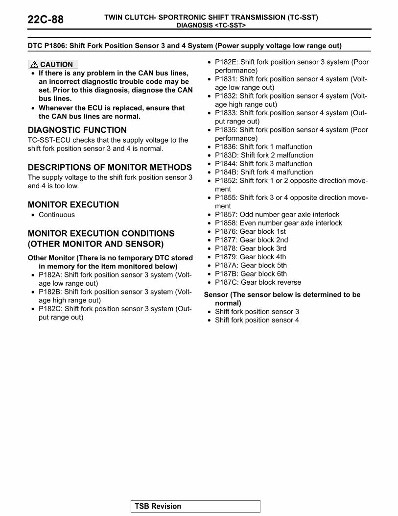
DIAGNOSIS <TC-SST>TWIN CLUTCH- SPORTRONIC SHIFT TRANSMISSION (TC-SST)22C-88
DTC P1806: Shift Fork Position Sensor 3 and 4 System (Power supply voltage low range out)
CAUTION• If there is any problem in the CAN bus lines,
an incorrect diagnostic trouble code may be set. Prior to this diagnosis, diagnose the CAN bus lines.
• Whenever the ECU is replaced, ensure that the CAN bus lines are normal.
.
DIAGNOSTIC FUNCTIONTC-SST-ECU checks that the supply voltage to the shift fork position sensor 3 and 4 is normal..
DESCRIPTIONS OF MONITOR METHODSThe supply voltage to the shift fork position sensor 3 and 4 is too low..
MONITOR EXECUTION• Continuous
.
MONITOR EXECUTION CONDITIONS (OTHER MONITOR AND SENSOR)Other Monitor (There is no temporary DTC stored
in memory for the item monitored below)• P182A: Shift fork position sensor 3 system (Volt-
age low range out)• P182B: Shift fork position sensor 3 system (Volt-
age high range out)• P182C: Shift fork position sensor 3 system (Out-
put range out)
• P182E: Shift fork position sensor 3 system (Poor performance)
• P1831: Shift fork position sensor 4 system (Volt-age low range out)
• P1832: Shift fork position sensor 4 system (Volt-age high range out)
• P1833: Shift fork position sensor 4 system (Out-put range out)
• P1835: Shift fork position sensor 4 system (Poor performance)
• P1836: Shift fork 1 malfunction• P183D: Shift fork 2 malfunction• P1844: Shift fork 3 malfunction• P184B: Shift fork 4 malfunction• P1852: Shift fork 1 or 2 opposite direction move-
ment• P1855: Shift fork 3 or 4 opposite direction move-
ment• P1857: Odd number gear axle interlock• P1858: Even number gear axle interlock• P1876: Gear block 1st• P1877: Gear block 2nd• P1878: Gear block 3rd• P1879: Gear block 4th• P187A: Gear block 5th• P187B: Gear block 6th• P187C: Gear block reverse
Sensor (The sensor below is determined to be normal)
• Shift fork position sensor 3• Shift fork position sensor 4
.
TSB Revision

DIAGNOSIS <TC-SST>TWIN CLUTCH- SPORTRONIC SHIFT TRANSMISSION (TC-SST) 22C-89
LOGIC FLOW CHARTS (Monitor Sequence)
.
DTC SET CONDITIONSCheck Conditions• Voltage of battery: 8 V or more.• Voltage of battery: 16.5 V or less.
JUDGMENT CRITERIA• Supply voltage: 3.07 V or less. (140 millisecond)
.
OBD-II DRIVE CYCLE PATTERNThe supply voltage remains 3.07 V or more for 140 milliseconds..
PROBABLE CAUSES• Malfunction of TC-SST-ECU
DIAGNOSTIC PROCEDURE
STEP 1. Scan tool CAN bus diagnosticsUsing scan tool MB991958, diagnose the CAN bus lines.Q: Is the check result normal?
YES : Go to Step 2.NO : Repair the CAN bus lines. (Refer to GROUP 54C −
Troubleshooting P.54C-14.) After repairing the CAN bus line, go to Step 2.
STEP 2. Check whether the DTC is reset.Q: Is DTC No. P1806 set?
YES : Replace the TC-SST assembly. (Refer to P.22C-341.)NO : Intermittent malfunction. (Refer to GROUP 00 − How
to Cope with Intermittent Malfunction P.00-15.)
AC710669
START
No
GoodMalfunction
END
Monitoring condition met
Continuous failurefor 140 msec
No
Yes
Yes
Yes
NoSensor supply < 3.07 V
TSB Revision

DIAGNOSIS <TC-SST>TWIN CLUTCH- SPORTRONIC SHIFT TRANSMISSION (TC-SST)22C-90
DTC P1807: Shift Fork Position Sensor 3 and 4 System (Power supply voltage high range out)
CAUTION• If there is any problem in the CAN bus lines,
an incorrect diagnostic trouble code may be set. Prior to this diagnosis, diagnose the CAN bus lines.
• Whenever the ECU is replaced, ensure that the CAN bus lines are normal.
.
DIAGNOSTIC FUNCTIONTC-SST-ECU checks that the supply voltage to the shift fork position sensor 3 and 4 is normal..
DESCRIPTIONS OF MONITOR METHODSThe supply voltage to the shift fork position sensor 3 and 4 is too high..
MONITOR EXECUTION• Continuous
.
MONITOR EXECUTION CONDITIONS (OTHER MONITOR AND SENSOR)Other Monitor (There is no temporary DTC stored
in memory for the item monitored below)• P182A: Shift fork position sensor 3 system (Volt-
age low range out)• P182B: Shift fork position sensor 3 system (Volt-
age high range out)• P182C: Shift fork position sensor 3 system (Out-
put range out)
• P182E: Shift fork position sensor 3 system (Poor performance)
• P1831: Shift fork position sensor 4 system (Volt-age low range out)
• P1832: Shift fork position sensor 4 system (Volt-age high range out)
• P1833: Shift fork position sensor 4 system (Out-put range out)
• P1835: Shift fork position sensor 4 system (Poor performance)
• P1836: Shift fork 1 malfunction• P183D: Shift fork 2 malfunction• P1844: Shift fork 3 malfunction• P184B: Shift fork 4 malfunction• P1852: Shift fork 1 or 2 opposite direction move-
ment• P1855: Shift fork 3 or 4 opposite direction move-
ment• P1857: Odd number gear axle interlock• P1858: Even number gear axle interlock• P1876: Gear block 1st• P1877: Gear block 2nd• P1878: Gear block 3rd• P1879: Gear block 4th• P187A: Gear block 5th• P187B: Gear block 6th• P187C: Gear block reverse
Sensor (The sensor below is determined to be normal)
• Shift fork position sensor 3• Shift fork position sensor 4
.
TSB Revision

DIAGNOSIS <TC-SST>TWIN CLUTCH- SPORTRONIC SHIFT TRANSMISSION (TC-SST) 22C-91
LOGIC FLOW CHARTS (Monitor Sequence)
.
DTC SET CONDITIONSCheck Conditions• Voltage of battery: 8 V or more.• Voltage of battery: 16.5 V or less.
JUDGMENT CRITERIA• Supply voltage: 3.25 V or more. (140 millisecond)
.
OBD-II DRIVE CYCLE PATTERNThe supply voltage remains 3.25 V or less for 140 milliseconds..
PROBABLE CAUSES• Malfunction of TC-SST-ECU
DIAGNOSTIC PROCEDURE
STEP 1. Scan tool CAN bus diagnosticsUsing scan tool MB991958, diagnose the CAN bus lines.Q: Is the check result normal?
YES : Go to Step 2.NO : Repair the CAN bus lines. (Refer to GROUP 54C −
Troubleshooting P.54C-14.) After repairing the CAN bus line, go to Step 2.
STEP 2. Check whether the DTC is reset.Q: Is DTC No. P1807 set?
YES : Replace the TC-SST assembly. (Refer to P.22C-341.)NO : Intermittent malfunction. (Refer to GROUP 00 − How
to Cope with Intermittent Malfunction P.00-15.)
AC710670
START
No
GoodMalfunction
END
Monitoring condition met
Continuous failurefor 140 msec
No
Yes
Yes
Yes
NoSensor supply > 3.25 V
TSB Revision

DIAGNOSIS <TC-SST>TWIN CLUTCH- SPORTRONIC SHIFT TRANSMISSION (TC-SST)22C-92
DTC P1808: TC-SST-ECU temperature, fluid temperature sensor system (Correlation error)
CAUTION• If there is any problem in the CAN bus lines,
an incorrect diagnostic trouble code may be set. Prior to this diagnosis, diagnose the CAN bus lines.
• Whenever the ECU is replaced, ensure that the CAN bus lines are normal.
.
DIAGNOSTIC FUNCTIONTC-SST-ECU checks that the temperature sensor and the fluid temperature sensor are normal..
DESCRIPTIONS OF MONITOR METHODSThe difference of the output between the ECU tem-perature sensor and fluid temperature sensor is large..
MONITOR EXECUTION CONDITIONS (OTHER MONITOR AND SENSOR)Other Monitor (There is no temporary DTC stored
in memory for the item monitored below)• Not applicable
Sensor (The sensor below is determined to be normal)
• Not applicable.
LOGIC FLOW CHARTS (Monitor Sequence)
.
DTC SET CONDITIONSCheck Conditions• Voltage of battery: 8 V or more.• Voltage of battery: 16.5 V or less.
JUDGMENT CRITERIA• Calculated temperature ("Temperature B: Fluid
temperature sensor output" − "Temperature A: TC-SST-ECU temperature sensor output"): 20° C (36° F) or more. (12 seconds)
.
AC710595
START
No
Yes
Yes
GoodMalfunction
END
Monitoring condition met
No
Continuous failure for 12 secNo
Yes
|Temperature B -Temperature A|> 20 ˚C (36 ˚F)
Temperature B: Fluid temperature sensor outputTemperature A: TC-SST-ECU temperature sensor output
TSB Revision

DIAGNOSIS <TC-SST>TWIN CLUTCH- SPORTRONIC SHIFT TRANSMISSION (TC-SST) 22C-93
OBD-II DRIVE CYCLE PATTERNThe difference of the calculated temperature is 20° C (36° F) or less..
PROBABLE CAUSES• Malfunction of TC-SST-ECU
DIAGNOSTIC PROCEDURE
STEP 1. Scan tool CAN bus diagnosticsUsing scan tool MB991958, diagnose the CAN bus lines.Q: Is the check result normal?
YES : Go to Step 2.NO : Repair the CAN bus lines. (Refer to GROUP 54C −
Troubleshooting P.54C-14.) After repairing the CAN bus line, go to Step 2.
STEP 2. Check whether the DTC is reset.Q: Is DTC No. P1808 set?
YES : Replace the TC-SST assembly. (Refer to P.22C-341.)NO : Intermittent malfunction. (Refer to GROUP 00 − How
to Cope with Intermittent Malfunction P.00-15.)
DTC P180C: Clutch pressure cut spool sticking
CAUTION• If there is any problem in the CAN bus lines,
an incorrect diagnostic trouble code may be set. Prior to this diagnosis, diagnose the CAN bus lines.
• Whenever the ECU is replaced, ensure that the CAN bus lines are normal.
.
DIAGNOSTIC FUNCTIONTC-SST-ECU checks that the clutch pressure cut spool is normal..
DESCRIPTIONS OF MONITOR METHODSThe clutch pressure cut spool is determined to be seized..
PROBABLE CAUSES• Malfunction of TC-SST-ECU
DIAGNOSTIC PROCEDURE
STEP 1. Scan tool CAN bus diagnosticsUsing scan tool MB991958, diagnose the CAN bus lines.Q: Is the check result normal?
YES : Go to Step 2.NO : Repair the CAN bus lines. (Refer to GROUP 54C −
Troubleshooting P.54C-14.) After repairing the CAN bus line, go to Step 2.
STEP 2. Check whether the DTC is reset.Q: Is DTC No. P180C set?
YES : Replace the TC-SST assembly. (Refer to P.22C-341.)NO : Intermittent malfunction. (Refer to GROUP 00 − How
to Cope with Intermittent Malfunction P.00-15.)
TSB Revision

DIAGNOSIS <TC-SST>TWIN CLUTCH- SPORTRONIC SHIFT TRANSMISSION (TC-SST)22C-94
DTC P181B: Clutch 1 (Pressure low range out)
CAUTION• If there is any problem in the CAN bus lines,
an incorrect diagnostic trouble code may be set. Prior to this diagnosis, diagnose the CAN bus lines.
• Whenever the ECU is replaced, ensure that the CAN bus lines are normal.
.
DIAGNOSTIC FUNCTIONTC-SST-ECU checks that the clutch 1 pressure is normal..
DESCRIPTIONS OF MONITOR METHODSThe pressure of the clutch 1 is too low..
MONITOR EXECUTION• Continuous
.
MONITOR EXECUTION CONDITIONS (OTHER MONITOR AND SENSOR)Other Monitor (There is no temporary DTC stored
in memory for the item monitored below)• P0841: Clutch 1 pressure sensor system (Poor
performance)• P0842: Clutch 1 pressure sensor system (Output
low range out)• P0843: Clutch 1 pressure sensor system (Output
high range out)• P1836: Shift fork 1 malfunction• P183D: Shift fork 2 malfunction
Sensor (The sensor below is determined to be normal)
• Clutch 1 pressure sensor.
LOGIC FLOW CHARTS (Monitor Sequence)
.
DTC SET CONDITIONSCheck Conditions• Voltage of battery: 8 V or more.
• Voltage of battery: 16.5 V or less.• Engine speed: 500 r/min or more.• Time since above engine condition: 400 millisec-
ond or more.
AC710671
START
No
GoodMalfunction
END
Monitoring condition met
Continuous failurefor 5 sec
No
Yes
Yes
Yes
NoCalculated pressure > 2,000 mbar
TSB Revision

DIAGNOSIS <TC-SST>TWIN CLUTCH- SPORTRONIC SHIFT TRANSMISSION (TC-SST) 22C-95
• Clutch 1 (odd) state: Slip or engaged.• Clutch/shift pressure solenoid 1: Not OFF or not
in valve cleaning mode.
JUDGMENT CRITERIA• Calculated pressure: 2,000 mbar or more. (5 sec-
onds).
OBD-II DRIVE CYCLE PATTERNThe calculated pressure remains 2,000 mbar or less for 5 seconds. .
PROBABLE CAUSES• Malfunction of TC-SST-ECU
DIAGNOSTIC PROCEDURE
STEP 1. Scan tool CAN bus diagnosticsUsing scan tool MB991958, diagnose the CAN bus lines.Q: Is the check result normal?
YES : Go to Step 2.NO : Repair the CAN bus lines. (Refer to GROUP 54C −
Troubleshooting P.54C-14.) After repairing the CAN bus line, go to Step 2.
STEP 2. Check whether the DTC is reset.Q: Is DTC No. P181B set?
YES : Replace the TC-SST assembly. (Refer to P.22C-341.)NO : Intermittent malfunction. (Refer to GROUP 00 − How
to Cope with Intermittent Malfunction P.00-15.)
DTC P181C: Clutch 1 (Pressure high range out)
CAUTION• If there is any problem in the CAN bus lines,
an incorrect diagnostic trouble code may be set. Prior to this diagnosis, diagnose the CAN bus lines.
• Whenever the ECU is replaced, ensure that the CAN bus lines are normal.
.
DIAGNOSTIC FUNCTIONTC-SST-ECU checks that the clutch 1 pressure is normal..
DESCRIPTIONS OF MONITOR METHODSThe pressure of the clutch 1 is too high..
MONITOR EXECUTION• Continuous
.
MONITOR EXECUTION CONDITIONS (OTHER MONITOR AND SENSOR)Other Monitor (There is no temporary DTC stored
in memory for the item monitored below)• P0841: Clutch 1 pressure sensor system (Poor
performance)• P0842: Clutch 1 pressure sensor system (Output
low range out)• P0843: Clutch 1 pressure sensor system (Output
high range out)• P1836: Shift fork 1 malfunction• P183D: Shift fork 2 malfunction
Sensor (The sensor below is determined to be normal)
• Clutch 1 pressure sensor.
TSB Revision

DIAGNOSIS <TC-SST>TWIN CLUTCH- SPORTRONIC SHIFT TRANSMISSION (TC-SST)22C-96
LOGIC FLOW CHARTS (Monitor Sequence) <Target clutch 1 (odd) pressure: 3,000 mbar or more>
.
DTC SET CONDITIONS <TARGET CLUTCH 1 (ODD) PRESSURE: 3,000 MBAR OR MORE>Check Conditions• Engine speed: 500 r/min or more.• Time since above engine condition: 400 millisec-
ond or more.• Clutch 1 (odd) state: Slip or engaged.• Target clutch 1 (odd) pressure: 3,000 mbar or
more.
JUDGMENT CRITERIA• Calculated pressure: −5,000 mbar or less. (220
millisecond).
OBD-II DRIVE CYCLE PATTERN <TARGET CLUTCH 1 (ODD) PRESSURE: 3,000 MBAR OR MORE>The calculated pressure remains −5,000 mbar or more for 220 milliseconds. .
AC710672
START
No
GoodMalfunction
END
Monitoring condition met
Continuous failurefor 220 msec
No
Yes
Yes
Yes
NoCalculated pressure< -5,000 mbar
TSB Revision

DIAGNOSIS <TC-SST>TWIN CLUTCH- SPORTRONIC SHIFT TRANSMISSION (TC-SST) 22C-97
LOGIC FLOW CHARTS (Monitor Sequence) <Target clutch 1 (odd) pressure: 1,400 mbar or more to 3,000 mbar or less>
.
DTC SET CONDITIONS <TARGET CLUTCH 1 (ODD) PRESSURE: 1,400 MBAR OR MORE TO 3,000 MBAR OR LESS>Check Conditions• Engine speed: 500 r/min or more.• Time since above engine condition: 400 millisec-
ond or more.• Clutch 1 (odd) state: Slip or engaged.• Target clutch 1 (odd) pressure: 1,400 mbar or
more.
JUDGMENT CRITERIA• Calculated pressure: −2,000 mbar or less. (220
millisecond).
OBD-II DRIVE CYCLE PATTERN <TARGET CLUTCH 1 (ODD) PRESSURE: 1,400 MBAR OR MORE TO 3,000 MBAR OR LESS>The calculated pressure remains −2,000 mbar or more for 220 milliseconds. .
AC710673
START
No
GoodMalfunction
END
Monitoring condition met
Continuous failurefor 220 msec
No
Yes
Yes
Yes
NoCalculated pressure< -2,000 mbar
TSB Revision

DIAGNOSIS <TC-SST>TWIN CLUTCH- SPORTRONIC SHIFT TRANSMISSION (TC-SST)22C-98
LOGIC FLOW CHARTS (Monitor Sequence) <Target clutch 1 (odd) pressure: 1,400 mbar or less>
.
DTC SET CONDITIONS <TARGET CLUTCH 1 (ODD) PRESSURE: 1,400 MBAR OR LESS>Check Conditions• Engine speed: 500 r/min or more.• Time since above engine condition: 400 millisec-
ond or more.• Clutch 1 (odd) state: Slip or engaged.• Target clutch 1 (odd) pressure: 1,400 mbar or
less.
JUDGMENT CRITERIA• Calculated pressure: −1,000 mbar or less. (220
millisecond).
OBD-II DRIVE CYCLE PATTERN <TARGET CLUTCH 1 (ODD) PRESSURE: 1,400 MBAR OR LESS>The clutch 1 (odd) pressure remains −1,000 mbar or more for 220 milliseconds. .
PROBABLE CAUSES• Malfunction of TC-SST-ECU
DIAGNOSTIC PROCEDURE
STEP 1. Scan tool CAN bus diagnosticsUsing scan tool MB991958, diagnose the CAN bus lines.Q: Is the check result normal?
YES : Go to Step 2.NO : Repair the CAN bus lines. (Refer to GROUP 54C −
Troubleshooting P.54C-14.) After repairing the CAN bus line, go to Step 2.
AC710674
START
No
GoodMalfunction
END
Monitoring condition met
Continuous failurefor 220 msec
No
Yes
Yes
Yes
NoCalculated pressure< -1,000 mbar
TSB Revision
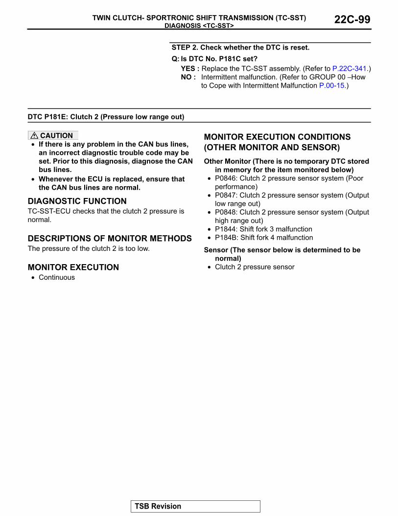
DIAGNOSIS <TC-SST>TWIN CLUTCH- SPORTRONIC SHIFT TRANSMISSION (TC-SST) 22C-99
STEP 2. Check whether the DTC is reset.Q: Is DTC No. P181C set?
YES : Replace the TC-SST assembly. (Refer to P.22C-341.)NO : Intermittent malfunction. (Refer to GROUP 00 − How
to Cope with Intermittent Malfunction P.00-15.)
DTC P181E: Clutch 2 (Pressure low range out)
CAUTION• If there is any problem in the CAN bus lines,
an incorrect diagnostic trouble code may be set. Prior to this diagnosis, diagnose the CAN bus lines.
• Whenever the ECU is replaced, ensure that the CAN bus lines are normal.
.
DIAGNOSTIC FUNCTIONTC-SST-ECU checks that the clutch 2 pressure is normal..
DESCRIPTIONS OF MONITOR METHODSThe pressure of the clutch 2 is too low..
MONITOR EXECUTION• Continuous
.
MONITOR EXECUTION CONDITIONS (OTHER MONITOR AND SENSOR)Other Monitor (There is no temporary DTC stored
in memory for the item monitored below)• P0846: Clutch 2 pressure sensor system (Poor
performance)• P0847: Clutch 2 pressure sensor system (Output
low range out)• P0848: Clutch 2 pressure sensor system (Output
high range out)• P1844: Shift fork 3 malfunction• P184B: Shift fork 4 malfunction
Sensor (The sensor below is determined to be normal)
• Clutch 2 pressure sensor.
TSB Revision

DIAGNOSIS <TC-SST>TWIN CLUTCH- SPORTRONIC SHIFT TRANSMISSION (TC-SST)22C-100
LOGIC FLOW CHARTS (Monitor Sequence)
.
DTC SET CONDITIONSCheck Conditions• Voltage of battery: 8 V or more.• Voltage of battery: 16.5 V or less.• Engine speed: 500 r/min or more.• Time since above engine condition: 400 millisec-
ond or more.• Clutch 2 (even) state: Slip or engaged.• Clutch/shift pressure solenoid 2: Not OFF or not
in valve cleaning mode.
JUDGMENT CRITERIA• Calculated pressure: 2,000 mbar or more. (5 sec-
onds).
OBD-II DRIVE CYCLE PATTERNThe calculated pressure remains 2,000 mbar or less for 5 seconds..
PROBABLE CAUSES• Malfunction of TC-SST-ECU
DIAGNOSTIC PROCEDURE
STEP 1. Scan tool CAN bus diagnosticsUsing scan tool MB991958, diagnose the CAN bus lines.Q: Is the check result normal?
YES : Go to Step 2.NO : Repair the CAN bus lines. (Refer to GROUP 54C −
Troubleshooting P.54C-14.) After repairing the CAN bus line, go to Step 2.
AC710671
START
No
GoodMalfunction
END
Monitoring condition met
Continuous failurefor 5 sec
No
Yes
Yes
Yes
NoCalculated pressure > 2,000 mbar
TSB Revision

DIAGNOSIS <TC-SST>TWIN CLUTCH- SPORTRONIC SHIFT TRANSMISSION (TC-SST) 22C-101
STEP 2. Check whether the DTC is reset.Q: Is DTC No. P181E set?
YES : Replace the TC-SST assembly. (Refer to P.22C-341.)NO : Intermittent malfunction. (Refer to GROUP 00 − How
to Cope with Intermittent Malfunction P.00-15.)
DTC P181F: Clutch 2 (Pressure high range out)
CAUTION• If there is any problem in the CAN bus lines,
an incorrect diagnostic trouble code may be set. Prior to this diagnosis, diagnose the CAN bus lines.
• Whenever the ECU is replaced, ensure that the CAN bus lines are normal.
.
DIAGNOSTIC FUNCTIONTC-SST-ECU checks that the clutch 2 pressure is normal..
DESCRIPTIONS OF MONITOR METHODSThe pressure of the clutch 2 is too high..
MONITOR EXECUTION• Continuous
.
MONITOR EXECUTION CONDITIONS (OTHER MONITOR AND SENSOR)Other Monitor (There is no temporary DTC stored
in memory for the item monitored below)• P0846: Clutch 2 pressure sensor system (Poor
performance)• P0847: Clutch 2 pressure sensor system (Output
low range out)• P0848: Clutch 2 pressure sensor system (Output
high range out)• P1844: Shift fork 3 malfunction• P184B: Shift fork 4 malfunction
Sensor (The sensor below is determined to be normal)
• Clutch 2 pressure sensor.
TSB Revision

DIAGNOSIS <TC-SST>TWIN CLUTCH- SPORTRONIC SHIFT TRANSMISSION (TC-SST)22C-102
LOGIC FLOW CHARTS (Monitor Sequence) <Target clutch 2 (even) pressure: 3,000 mbar or more>
.
DTC SET CONDITIONS <TARGET CLUTCH 2 (EVEN) PRESSURE: 3,000 MBAR OR MORE>Check Conditions• Engine speed: 500 r/min or more.• Time since above engine condition: 400 millisec-
ond or more.• Clutch 2 (even) state: Slip or engaged.• Target clutch 2 (even) pressure: 3,000 mbar or
more.
JUDGMENT CRITERIA• Calculated pressure: −5,000 mbar or less. (220
millisecond).
OBD-II DRIVE CYCLE PATTERN <TARGET CLUTCH 2 (EVEN) PRESSURE: 3,000 MBAR OR MORE>The calculated pressure remains −5,000 mbar or more for 220 milliseconds..
AC710672
START
No
GoodMalfunction
END
Monitoring condition met
Continuous failurefor 220 msec
No
Yes
Yes
Yes
NoCalculated pressure< -5,000 mbar
TSB Revision

DIAGNOSIS <TC-SST>TWIN CLUTCH- SPORTRONIC SHIFT TRANSMISSION (TC-SST) 22C-103
LOGIC FLOW CHARTS (Monitor Sequence) <Target clutch 2 (even) pressure: 1,400 mbar or more to 3,000 mbar or less>
.
DTC SET CONDITIONS <TARGET CLUTCH 2 (EVEN) PRESSURE: 1,400 MBAR OR MORE TO 3,000 MBAR OR LESS>Check Conditions• Engine speed: 500 r/min or more.• Time since above engine condition: 400 millisec-
ond or more.• Clutch 2 (even) state: Slip or engaged.• Target clutch 2 (even) pressure: 1,400 mbar or
more.
JUDGMENT CRITERIA• Calculated pressure: −2,000 mbar or less. (220
millisecond).
OBD-II DRIVE CYCLE PATTERN <TARGET CLUTCH 1 (ODD) PRESSURE: 1,400 MBAR OR MORE TO 3,000 MBAR OR LESS>The calculated pressure remains −2,000 mbar or more for 220 milliseconds. .
AC710673
START
No
GoodMalfunction
END
Monitoring condition met
Continuous failurefor 220 msec
No
Yes
Yes
Yes
NoCalculated pressure< -2,000 mbar
TSB Revision

DIAGNOSIS <TC-SST>TWIN CLUTCH- SPORTRONIC SHIFT TRANSMISSION (TC-SST)22C-104
LOGIC FLOW CHARTS (Monitor Sequence) <Target clutch 2 (even) pressure: 1,400 mbar or less>
.
DTC SET CONDITIONS <TARGET CLUTCH 2 (EVEN) PRESSURE: 1,400 MBAR OR LESS>Check Conditions• Engine speed: 500 r/min or more.• Time since above engine condition: 400 millisec-
ond or more.• Clutch 2 (even) state: Slip or engaged.• Target clutch 2 (even) pressure: 1,400 mbar or
less.
JUDGMENT CRITERIA• Calculated pressure: −1,000 mbar or less. (220
millisecond).
OBD-II DRIVE CYCLE PATTERN <TARGET CLUTCH 2 (EVEN) PRESSURE: 1,400 MBAR OR LESS>The clutch 2 (even) pressure remains −1,000 mbar or more for 220 milliseconds. .
PROBABLE CAUSES• Malfunction of TC-SST-ECU
DIAGNOSTIC PROCEDURE
STEP 1. Scan tool CAN bus diagnosticsUsing scan tool MB991958, diagnose the CAN bus lines.Q: Is the check result normal?
YES : Go to Step 2.NO : Repair the CAN bus lines. (Refer to GROUP 54C −
Troubleshooting P.54C-14.) After repairing the CAN bus line, go to Step 2.
AC710674
START
No
GoodMalfunction
END
Monitoring condition met
Continuous failurefor 220 msec
No
Yes
Yes
Yes
NoCalculated pressure< -1,000 mbar
TSB Revision

DIAGNOSIS <TC-SST>TWIN CLUTCH- SPORTRONIC SHIFT TRANSMISSION (TC-SST) 22C-105
STEP 2. Check whether the DTC is reset.Q: Is DTC No. P181F set?
YES : Replace the TC-SST assembly. (Refer to P.22C-341.)NO : Intermittent malfunction. (Refer to GROUP 00 − How
to Cope with Intermittent Malfunction P.00-15.)
DTC P1820: Shift Fork Position Sensor 1 System (Voltage low range out)
CAUTION• If there is any problem in the CAN bus lines,
an incorrect diagnostic trouble code may be set. Prior to this diagnosis, diagnose the CAN bus lines.
• Whenever the ECU is replaced, ensure that the CAN bus lines are normal.
.
DIAGNOSTIC FUNCTIONTC-SST-ECU checks that the voltage of the shift fork position sensor 1 is normal..
DESCRIPTIONS OF MONITOR METHODSThe voltage of the shift fork position sensor 1 is too low..
MONITOR EXECUTION• Continuous
.
MONITOR EXECUTION CONDITIONS (OTHER MONITOR AND SENSOR)Other Monitor (There is no temporary DTC stored
in memory for the item monitored below)• P1821: Shift fork position sensor 1 system (Volt-
age high range out)
• P1822: Shift fork position sensor 1 system (Out-put range out)
• P1823: Shift fork position sensor 1 system (Neu-tral)
• P1824: Shift fork position sensor 1 system (Poor performance)
• P1836: Shift fork 1 malfunction• P1852: Shift fork 1 or 2 opposite direction move-
ment• P1855: Shift fork 3 or 4 opposite direction move-
ment• P1857: Odd number gear axle interlock• P1876: Gear block 1st• P1877: Gear block 2nd• P1878: Gear block 3rd• P1879: Gear block 4th• P187A: Gear block 5th• P187B: Gear block 6th• P187C: Gear block reverse
Sensor (The sensor below is determined to be normal)
• Not applicable.
TSB Revision

DIAGNOSIS <TC-SST>TWIN CLUTCH- SPORTRONIC SHIFT TRANSMISSION (TC-SST)22C-106
LOGIC FLOW CHARTS (Monitor Sequence)
.
DTC SET CONDITIONSCheck Conditions• Voltage of battery: 8 V or more.• Voltage of battery: 16.5 V or less.
JUDGMENT CRITERIA• Position sensor voltage: 0.128 V or less. (160 mil-
lisecond)
.
OBD-II DRIVE CYCLE PATTERNThe position sensor voltage remains 0.128 V or more for 160 milliseconds..
PROBABLE CAUSES• Malfunction of TC-SST-ECU
DIAGNOSTIC PROCEDURE
STEP 1. Scan tool CAN bus diagnosticsUsing scan tool MB991958, diagnose the CAN bus lines.Q: Is the check result normal?
YES : Go to Step 2.NO : Repair the CAN bus lines. (Refer to GROUP 54C −
Troubleshooting P.54C-14.) After repairing the CAN bus line, go to Step 2.
STEP 2. Check whether the DTC is reset.Q: Is DTC No. P1820 set?
YES : Replace the TC-SST assembly. (Refer to P.22C-341.)NO : Intermittent malfunction. (Refer to GROUP 00 − How
to Cope with Intermittent Malfunction P.00-15.)
AC710676
START
No
GoodMalfunction
END
Monitoring condition met
Continuous failurefor 160 msec
No
Yes
Yes
Yes
NoShift fork position< 0.128 V
TSB Revision

DIAGNOSIS <TC-SST>TWIN CLUTCH- SPORTRONIC SHIFT TRANSMISSION (TC-SST) 22C-107
DTC P1821: Shift Fork Position Sensor 1 System (Voltage high range out)
CAUTION• If there is any problem in the CAN bus lines,
an incorrect diagnostic trouble code may be set. Prior to this diagnosis, diagnose the CAN bus lines.
• Whenever the ECU is replaced, ensure that the CAN bus lines are normal.
.
DIAGNOSTIC FUNCTIONTC-SST-ECU checks that the voltage of the shift fork position sensor 1 is normal..
DESCRIPTIONS OF MONITOR METHODSThe voltage of the shift fork position sensor 1 is too high..
MONITOR EXECUTION• Continuous
.
MONITOR EXECUTION CONDITIONS (OTHER MONITOR AND SENSOR)Other Monitor (There is no temporary DTC stored
in memory for the item monitored below)• P1820: Shift fork position sensor 1 system (Volt-
age low range out)
• P1822: Shift fork position sensor 1 system (Out-put range out)
• P1823: Shift fork position sensor 1 system (Neu-tral)
• P1824: Shift fork position sensor 1 system (Poor performance)
• P1836: Shift fork 1 malfunction• P1852: Shift fork 1 or 2 opposite direction move-
ment• P1855: Shift fork 3 or 4 opposite direction move-
ment• P1857: Odd number gear axle interlock• P1876: Gear block 1st• P1877: Gear block 2nd• P1878: Gear block 3rd• P1879: Gear block 4th• P187A: Gear block 5th• P187B: Gear block 6th• P187C: Gear block reverse
Sensor (The sensor below is determined to be normal)
• Not applicable.
TSB Revision

DIAGNOSIS <TC-SST>TWIN CLUTCH- SPORTRONIC SHIFT TRANSMISSION (TC-SST)22C-108
LOGIC FLOW CHARTS (Monitor Sequence)
.
DTC SET CONDITIONSCheck Conditions• Voltage of battery: 8 V or more.• Voltage of battery: 16.5 V or less.
JUDGMENT CRITERIA• Position sensor voltage: 3.008 V or more. (160
millisecond)
.
OBD-II DRIVE CYCLE PATTERNThe position sensor voltage remains 3.008 V or less for 160 milliseconds..
PROBABLE CAUSES• Malfunction of TC-SST-ECU
DIAGNOSTIC PROCEDURE
STEP 1. Scan tool CAN bus diagnosticsUsing scan tool MB991958, diagnose the CAN bus lines.Q: Is the check result normal?
YES : Go to Step 2.NO : Repair the CAN bus lines. (Refer to GROUP 54C −
Troubleshooting P.54C-14.) After repairing the CAN bus line, go to Step 2.
STEP 2. Check whether the DTC is reset.Q: Is DTC No. P1821 set?
YES : Replace the TC-SST assembly. (Refer to P.22C-341.)NO : Intermittent malfunction. (Refer to GROUP 00 − How
to Cope with Intermittent Malfunction P.00-15.)
AC710680
START
No
GoodMalfunction
END
Monitoring condition met
Continuous failurefor 160 msec
No
Yes
Yes
Yes
NoShift fork position> 3.008 V
TSB Revision

DIAGNOSIS <TC-SST>TWIN CLUTCH- SPORTRONIC SHIFT TRANSMISSION (TC-SST) 22C-109
DTC P1822: Shift Fork Position Sensor 1 System (Output range out)
CAUTION• If there is any problem in the CAN bus lines,
an incorrect diagnostic trouble code may be set. Prior to this diagnosis, diagnose the CAN bus lines.
• Whenever the ECU is replaced, ensure that the CAN bus lines are normal.
.
DIAGNOSTIC FUNCTIONTC-SST-ECU checks that the output of the shift fork position sensor 1 is normal..
DESCRIPTIONS OF MONITOR METHODSThe output of the shift fork position sensor 1 is deter-mined to be abnormal..
MONITOR EXECUTION• Continuous
.
MONITOR EXECUTION CONDITIONS (OTHER MONITOR AND SENSOR)Other Monitor (There is no temporary DTC stored
in memory for the item monitored below)• P1820: Shift fork position sensor 1 system (Volt-
age low range out)
• P1821: Shift fork position sensor 1 system (Volt-age high range out)
• P1823: Shift fork position sensor 1 system (Neu-tral)
• P1824: Shift fork position sensor 1 system (Poor performance)
• P1836: Shift fork 1 malfunction• P1852: Shift fork 1 or 2 opposite direction move-
ment• P1855: Shift fork 3 or 4 opposite direction move-
ment• P1857: Odd number gear axle interlock• P1876: Gear block 1st• P1877: Gear block 2nd• P1878: Gear block 3rd• P1879: Gear block 4th• P187A: Gear block 5th• P187B: Gear block 6th• P187C: Gear block reverse
Sensor (The sensor below is determined to be normal)
• Not applicable.
TSB Revision
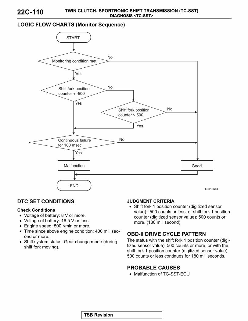
DIAGNOSIS <TC-SST>TWIN CLUTCH- SPORTRONIC SHIFT TRANSMISSION (TC-SST)22C-110
LOGIC FLOW CHARTS (Monitor Sequence)
.
DTC SET CONDITIONSCheck Conditions• Voltage of battery: 8 V or more.• Voltage of battery: 16.5 V or less.• Engine speed: 500 r/min or more.• Time since above engine condition: 400 millisec-
ond or more.• Shift system status: Gear change mode (during
shift fork moving).
JUDGMENT CRITERIA• Shift fork 1 position counter (digitized sensor
value): −500 counts or less, or shift fork 1 position counter (digitized sensor value): 500 counts or more. (180 millisecond)
.
OBD-II DRIVE CYCLE PATTERNThe status with the shift fork 1 position counter (digi-tized sensor value) −500 counts or more, or with the shift fork 1 position counter (digitized sensor value) 500 counts or less continues for 180 milliseconds..
PROBABLE CAUSES• Malfunction of TC-SST-ECU
AC710681
START
No
GoodMalfunction
END
Continuous failurefor 180 msec
No
Yes
Yes
Yes
No
NoShift fork positioncounter < -500
Yes
Shift fork positioncounter > 500
Monitoring condition met
TSB Revision

DIAGNOSIS <TC-SST>TWIN CLUTCH- SPORTRONIC SHIFT TRANSMISSION (TC-SST) 22C-111
DIAGNOSTIC PROCEDURE
STEP 1. Scan tool CAN bus diagnosticsUsing scan tool MB991958, diagnose the CAN bus lines.Q: Is the check result normal?
YES : Go to Step 2.NO : Repair the CAN bus lines. (Refer to GROUP 54C −
Troubleshooting P.54C-14.) After repairing the CAN bus line, go to Step 2.
STEP 2. Check whether the DTC is reset.Q: Is DTC No. P1822 set?
YES : Replace the TC-SST assembly. (Refer to P.22C-341.)NO : Intermittent malfunction. (Refer to GROUP 00 − How
to Cope with Intermittent Malfunction P.00-15.)
DTC P1823: Shift Fork Position Sensor 1 System (Neutral)
CAUTION• If there is any problem in the CAN bus lines,
an incorrect diagnostic trouble code may be set. Prior to this diagnosis, diagnose the CAN bus lines.
• Whenever the ECU is replaced, ensure that the CAN bus lines are normal.
.
DIAGNOSTIC FUNCTIONTC-SST-ECU checks that the shift fork position sen-sor 1 is normal..
DESCRIPTIONS OF MONITOR METHODSThe shift fork position sensor 1 is determined to be abnormal..
MONITOR EXECUTION• Continuous
.
MONITOR EXECUTION CONDITIONS (OTHER MONITOR AND SENSOR)Other Monitor (There is no temporary DTC stored
in memory for the item monitored below)• P1820: Shift fork position sensor 1 system (Volt-
age low range out)
• P1821: Shift fork position sensor 1 system (Volt-age high range out)
• P1822: Shift fork position sensor 1 system (Out-put range out)
• P1824: Shift fork position sensor 1 system (Poor performance)
• P1836: Shift fork 1 malfunction• P1852: Shift fork 1 or 2 opposite direction move-
ment• P1855: Shift fork 3 or 4 opposite direction move-
ment• P1857: Odd number gear axle interlock• P1876: Gear block 1st• P1877: Gear block 2nd• P1878: Gear block 3rd• P1879: Gear block 4th• P187A: Gear block 5th• P187B: Gear block 6th• P187C: Gear block reverse
Sensor (The sensor below is determined to be normal)
• Not applicable.
TSB Revision

DIAGNOSIS <TC-SST>TWIN CLUTCH- SPORTRONIC SHIFT TRANSMISSION (TC-SST)22C-112
LOGIC FLOW CHARTS (Monitor Sequence)
.
DTC SET CONDITIONSCheck Conditions• Voltage of battery: 8 V or more.• Voltage of battery: 16.5 V or less.• Engine speed: 500 r/min or more.• Time since above engine condition: 400 millisec-
ond or more.• Input shaft 1 (odd) speed: 500 r/min or more.• Input shaft 2 (even) speed: 500 r/min or more.• Shift fork 1 position: Neutral.• Input shaft 2 (even) gear: Engaged.• Engine speed − input shaft 2 speed: 50 r/min or
less.
JUDGMENT CRITERIA• Calculated speed: 40 r/min or less. (500 millisec-
ond).
OBD-II DRIVE CYCLE PATTERNThe calculated speed remains 40 r/min or more for 500 milliseconds..
PROBABLE CAUSES• Malfunction of TC-SST-ECU
DIAGNOSTIC PROCEDURE
STEP 1. Scan tool CAN bus diagnosticsUsing scan tool MB991958, diagnose the CAN bus lines.Q: Is the check result normal?
YES : Go to Step 2.NO : Repair the CAN bus lines. (Refer to GROUP 54C −
Troubleshooting P.54C-14.) After repairing the CAN bus line, go to Step 2.
AC711383
START
No
GoodMalfunction
END
Monitoring condition met
Continuous failurefor 500 msec
No
Yes
Yes
Yes
NoCalculated input shaft speed
TSB Revision

DIAGNOSIS <TC-SST>TWIN CLUTCH- SPORTRONIC SHIFT TRANSMISSION (TC-SST) 22C-113
STEP 2. Check whether the DTC is reset.Q: Is DTC No. P1823 set?
YES : Replace the TC-SST assembly. (Refer to P.22C-341.)NO : Intermittent malfunction. (Refer to GROUP 00 − How
to Cope with Intermittent Malfunction P.00-15.)
DTC P1824: Shift Fork Position Sensor 1 System (Poor performance)
CAUTION• If there is any problem in the CAN bus lines,
an incorrect diagnostic trouble code may be set. Prior to this diagnosis, diagnose the CAN bus lines.
• Whenever the ECU is replaced, ensure that the CAN bus lines are normal.
.
DIAGNOSTIC FUNCTIONTC-SST-ECU checks that the shift fork position sen-sor 1 is normal..
DESCRIPTIONS OF MONITOR METHODSThe shift fork position sensor 1 is determined to be abnormal..
MONITOR EXECUTION• Continuous
.
MONITOR EXECUTION CONDITIONS (OTHER MONITOR AND SENSOR)Other Monitor (There is no temporary DTC stored
in memory for the item monitored below)• P1820: Shift fork position sensor 1 system (Volt-
age low range out)
• P1821: Shift fork position sensor 1 system (Volt-age high range out)
• P1822: Shift fork position sensor 1 system (Out-put range out)
• P1823: Shift fork position sensor 1 system (Neu-tral)
• P1836: Shift fork 1 malfunction• P1852: Shift fork 1 or 2 opposite direction move-
ment• P1855: Shift fork 3 or 4 opposite direction move-
ment• P1857: Odd number gear axle interlock• P1876: Gear block 1st• P1877: Gear block 2nd• P1878: Gear block 3rd• P1879: Gear block 4th• P187A: Gear block 5th• P187B: Gear block 6th• P187C: Gear block reverse
Sensor (The sensor below is determined to be normal)
• Not applicable.
TSB Revision

DIAGNOSIS <TC-SST>TWIN CLUTCH- SPORTRONIC SHIFT TRANSMISSION (TC-SST)22C-114
LOGIC FLOW CHARTS (Monitor Sequence) <Shift fork 1 current gear: 1st gear>
.
DTC SET CONDITIONS <SHIFT FORK 1 CURRENT GEAR: 1ST GEAR>Check Conditions• Voltage of battery: 8 V or more.• Voltage of battery: 16.5 V or less.• Engine speed: 500 r/min or more.• Time since above engine condition: 400 millisec-
ond or more.• Input shaft 1 (odd) speed: 500 r/min or more.• Shift fork 1 current gear: 1st gear.
• Synchro (1st gear) slip speed: 80 r/min or more.• Requested shift fork: Not shift fork 1.
JUDGMENT CRITERIA• Shift fork 1 position: 6 mm (0.24 inch) or less.
(250 millisecond).
OBD-II DRIVE CYCLE PATTERN <SHIFT FORK 1 CURRENT GEAR: 1ST GEAR>The travel distance of the shift fork 1 remains 6 mm (0.24 inch) or more for 250 milliseconds..
AC710682
START
No
GoodMalfunction
END
Monitoring condition met
Continuous failurefor 250 msec
No
Yes
Yes
Yes
NoShift fork position< 6 mm (0.24 inch)
TSB Revision

DIAGNOSIS <TC-SST>TWIN CLUTCH- SPORTRONIC SHIFT TRANSMISSION (TC-SST) 22C-115
LOGIC FLOW CHARTS (Monitor Sequence) <Shift fork 1 current gear: Reverse gear>
.
DTC SET CONDITIONS <SHIFT FORK 1 CURRENT GEAR: REVERSE GEAR>Check Conditions• Voltage of battery: 8 V or more.• Voltage of battery: 16.5 V or less.• Engine speed: 500 r/min or more.• Time since above engine condition: 400 millisec-
ond or more.• Input shaft 1 (odd) speed: 500 r/min or more.• Shift fork 1 current gear: Reverse gear.• Synchro (reverse gear) slip speed: 80 r/min or
more.• Requested shift fork: Not shift fork 1.
JUDGMENT CRITERIA• Shift fork 1 position: −6 mm (−0.24 inch) or more.
(250 millisecond).
OBD-II DRIVE CYCLE PATTERN <SHIFT FORK 1 CURRENT GEAR: REVERSE GEAR>The travel distance of the shift fork 1 remains −6 mm (−0.24 inch) or less for 250 milliseconds..
PROBABLE CAUSES• Malfunction of TC-SST-ECU
DIAGNOSTIC PROCEDURE
STEP 1. Scan tool CAN bus diagnosticsUsing scan tool MB991958, diagnose the CAN bus lines.Q: Is the check result normal?
YES : Go to Step 2.NO : Repair the CAN bus lines. (Refer to GROUP 54C −
Troubleshooting P.54C-14.) After repairing the CAN bus line, go to Step 2.
AC710683
START
No
GoodMalfunction
END
Monitoring condition met
Continuous failurefor 250 msec
No
Yes
Yes
Yes
NoShift fork position> -6 mm (-0.24 inch)
TSB Revision

DIAGNOSIS <TC-SST>TWIN CLUTCH- SPORTRONIC SHIFT TRANSMISSION (TC-SST)22C-116
STEP 2. Check whether the DTC is reset.Q: Is DTC No. P1824 set?
YES : Replace the TC-SST assembly. (Refer to P.22C-341.)NO : Intermittent malfunction. (Refer to GROUP 00 − How
to Cope with Intermittent Malfunction P.00-15.)
DTC P1825: Shift Fork Position Sensor 2 System (Voltage low range out)
CAUTION• If there is any problem in the CAN bus lines,
an incorrect diagnostic trouble code may be set. Prior to this diagnosis, diagnose the CAN bus lines.
• Whenever the ECU is replaced, ensure that the CAN bus lines are normal.
.
DIAGNOSTIC FUNCTIONTC-SST-ECU checks that the voltage of the shift fork position sensor 2 is normal..
DESCRIPTIONS OF MONITOR METHODSThe voltage of the shift fork position sensor 2 is too low..
MONITOR EXECUTION• Continuous
.
MONITOR EXECUTION CONDITIONS (OTHER MONITOR AND SENSOR)Other Monitor (There is no temporary DTC stored
in memory for the item monitored below)• P1826: Shift fork position sensor 2 system (Volt-
age high range out)
• P1827: Shift fork position sensor 2 system (Out-put range out)
• P1828: Shift fork position sensor 2 system (Neu-tral)
• P1829: Shift fork position sensor 2 system (Poor performance)
• P183D: Shift fork 2 malfunction• P1852: Shift fork 1 or 2 opposite direction move-
ment• P1855: Shift fork 3 or 4 opposite direction move-
ment• P1857: Odd number gear axle interlock• P1876: Gear block 1st• P1877: Gear block 2nd• P1878: Gear block 3rd• P1879: Gear block 4th• P187A: Gear block 5th• P187B: Gear block 6th• P187C: Gear block reverse
Sensor (The sensor below is determined to be normal)
• Not applicable.
TSB Revision

DIAGNOSIS <TC-SST>TWIN CLUTCH- SPORTRONIC SHIFT TRANSMISSION (TC-SST) 22C-117
LOGIC FLOW CHARTS (Monitor Sequence)
.
DTC SET CONDITIONSCheck Conditions• Voltage of battery: 8 V or more.• Voltage of battery: 16.5 V or less.
JUDGMENT CRITERIA• Position sensor voltage: 0.128 V or less. (160 mil-
lisecond)
.
OBD-II DRIVE CYCLE PATTERNThe position sensor voltage remains 0.128 V or more for 160 milliseconds..
PROBABLE CAUSES• Malfunction of TC-SST-ECU
DIAGNOSTIC PROCEDURE
STEP 1. Scan tool CAN bus diagnosticsUsing scan tool MB991958, diagnose the CAN bus lines.Q: Is the check result normal?
YES : Go to Step 2.NO : Repair the CAN bus lines. (Refer to GROUP 54C −
Troubleshooting P.54C-14.) After repairing the CAN bus line, go to Step 2.
STEP 2. Check whether the DTC is reset.Q: Is DTC No. P1825 set?
YES : Replace the TC-SST assembly. (Refer to P.22C-341.)NO : Intermittent malfunction. (Refer to GROUP 00 − How
to Cope with Intermittent Malfunction P.00-15.)
AC710676
START
No
GoodMalfunction
END
Monitoring condition met
Continuous failurefor 160 msec
No
Yes
Yes
Yes
NoShift fork position< 0.128 V
TSB Revision

DIAGNOSIS <TC-SST>TWIN CLUTCH- SPORTRONIC SHIFT TRANSMISSION (TC-SST)22C-118
DTC P1826: Shift Fork Position Sensor 2 System (Voltage high range out)
CAUTION• If there is any problem in the CAN bus lines,
an incorrect diagnostic trouble code may be set. Prior to this diagnosis, diagnose the CAN bus lines.
• Whenever the ECU is replaced, ensure that the CAN bus lines are normal.
.
DIAGNOSTIC FUNCTIONTC-SST-ECU checks that the voltage of the shift fork position sensor 2 is normal..
DESCRIPTIONS OF MONITOR METHODSThe voltage of the shift fork position sensor 2 is too high..
MONITOR EXECUTION• Continuous
.
MONITOR EXECUTION CONDITIONS (OTHER MONITOR AND SENSOR)Other Monitor (There is no temporary DTC stored
in memory for the item monitored below)• P1825: Shift fork position sensor 2 system (Volt-
age low range out)
• P1827: Shift fork position sensor 2 system (Out-put range out)
• P1828: Shift fork position sensor 2 system (Neu-tral)
• P1829: Shift fork position sensor 2 system (Poor performance)
• P183D: Shift fork 2 malfunction• P1852: Shift fork 1 or 2 opposite direction move-
ment• P1855: Shift fork 3 or 4 opposite direction move-
ment• P1857: Odd number gear axle interlock• P1876: Gear block 1st• P1877: Gear block 2nd• P1878: Gear block 3rd• P1879: Gear block 4th• P187A: Gear block 5th• P187B: Gear block 6th• P187C: Gear block reverse
Sensor (The sensor below is determined to be normal)
• Not applicable.
TSB Revision

DIAGNOSIS <TC-SST>TWIN CLUTCH- SPORTRONIC SHIFT TRANSMISSION (TC-SST) 22C-119
LOGIC FLOW CHARTS (Monitor Sequence)
.
DTC SET CONDITIONSCheck Conditions• Voltage of battery: 8 V or more.• Voltage of battery: 16.5 V or less.
JUDGMENT CRITERIA• Position sensor voltage: 3.008 V or more. (160
millisecond)
.
OBD-II DRIVE CYCLE PATTERNThe position sensor voltage remains 3.008 V or less for 160 milliseconds..
PROBABLE CAUSES• Malfunction of TC-SST-ECU
DIAGNOSTIC PROCEDURE
STEP 1. Scan tool CAN bus diagnosticsUsing scan tool MB991958, diagnose the CAN bus lines.Q: Is the check result normal?
YES : Go to Step 2.NO : Repair the CAN bus lines. (Refer to GROUP 54C −
Troubleshooting P.54C-14.) After repairing the CAN bus line, go to Step 2.
STEP 2. Check whether the DTC is reset.Q: Is DTC No. P1826 set?
YES : Replace the TC-SST assembly. (Refer to P.22C-341.)NO : Intermittent malfunction. (Refer to GROUP 00 − How
to Cope with Intermittent Malfunction P.00-15.)
AC710680
START
No
GoodMalfunction
END
Monitoring condition met
Continuous failurefor 160 msec
No
Yes
Yes
Yes
NoShift fork position> 3.008 V
TSB Revision

DIAGNOSIS <TC-SST>TWIN CLUTCH- SPORTRONIC SHIFT TRANSMISSION (TC-SST)22C-120
DTC P1827: Shift Fork Position Sensor 2 System (Output range out)
CAUTION• If there is any problem in the CAN bus lines,
an incorrect diagnostic trouble code may be set. Prior to this diagnosis, diagnose the CAN bus lines.
• Whenever the ECU is replaced, ensure that the CAN bus lines are normal.
.
DIAGNOSTIC FUNCTIONTC-SST-ECU checks that the output of the shift fork position sensor 2 is normal..
DESCRIPTIONS OF MONITOR METHODSThe output of the shift fork position sensor 2 is deter-mined to be abnormal..
MONITOR EXECUTION• Continuous
.
MONITOR EXECUTION CONDITIONS (OTHER MONITOR AND SENSOR)Other Monitor (There is no temporary DTC stored
in memory for the item monitored below)• P1825: Shift fork position sensor 2 system (Volt-
age low range out)
• P1826: Shift fork position sensor 2 system (Volt-age high range out)
• P1828: Shift fork position sensor 2 system (Neu-tral)
• P1829: Shift fork position sensor 2 system (Poor performance)
• P183D: Shift fork 2 malfunction• P1852: Shift fork 1 or 2 opposite direction move-
ment• P1855: Shift fork 3 or 4 opposite direction move-
ment• P1857: Odd number gear axle interlock• P1876: Gear block 1st• P1877: Gear block 2nd• P1878: Gear block 3rd• P1879: Gear block 4th• P187A: Gear block 5th• P187B: Gear block 6th• P187C: Gear block reverse
Sensor (The sensor below is determined to be normal)
• Not applicable.
TSB Revision

DIAGNOSIS <TC-SST>TWIN CLUTCH- SPORTRONIC SHIFT TRANSMISSION (TC-SST) 22C-121
LOGIC FLOW CHARTS (Monitor Sequence)
.
DTC SET CONDITIONSCheck Conditions• Voltage of battery: 8 V or more.• Voltage of battery: 16.5 V or less.• Engine speed: 500 r/min or more.• Time since above engine condition: 400 millisec-
ond or more.• Shift system status: Gear change mode (during
shift fork moving).
JUDGMENT CRITERIA• Shift fork 2 position counter (digitized sensor
value): −500 counts or less, or shift fork 2 position counter (digitized sensor value): 500 counts or more. (180 millisecond)
.
OBD-II DRIVE CYCLE PATTERNThe status with the shift fork 2 position counter (digi-tized sensor value) −500 counts or more, or with the shift fork 2 position counter (digitized sensor value) 500 counts or less continues for 180 milliseconds..
PROBABLE CAUSES• Malfunction of TC-SST-ECU
AC710681
START
No
GoodMalfunction
END
Continuous failurefor 180 msec
No
Yes
Yes
Yes
No
NoShift fork positioncounter < -500
Yes
Shift fork positioncounter > 500
Monitoring condition met
TSB Revision

DIAGNOSIS <TC-SST>TWIN CLUTCH- SPORTRONIC SHIFT TRANSMISSION (TC-SST)22C-122
DIAGNOSTIC PROCEDURE
STEP 1. Scan tool CAN bus diagnosticsUsing scan tool MB991958, diagnose the CAN bus lines.Q: Is the check result normal?
YES : Go to Step 2.NO : Repair the CAN bus lines. (Refer to GROUP 54C −
Troubleshooting P.54C-14.) After repairing the CAN bus line, go to Step 2.
STEP 2. Check whether the DTC is reset.Q: Is DTC No. P1827 set?
YES : Replace the TC-SST assembly. (Refer to P.22C-341.)NO : Intermittent malfunction. (Refer to GROUP 00 − How
to Cope with Intermittent Malfunction P.00-15.)
DTC P1828: Shift Fork Position Sensor 2 System (Neutral)
CAUTION• If there is any problem in the CAN bus lines,
an incorrect diagnostic trouble code may be set. Prior to this diagnosis, diagnose the CAN bus lines.
• Whenever the ECU is replaced, ensure that the CAN bus lines are normal.
.
DIAGNOSTIC FUNCTIONTC-SST-ECU checks that the shift fork position sen-sor 2 is normal..
DESCRIPTIONS OF MONITOR METHODSThe shift fork position sensor 2 is determined to be abnormal..
MONITOR EXECUTION• Continuous
.
MONITOR EXECUTION CONDITIONS (OTHER MONITOR AND SENSOR)Other Monitor (There is no temporary DTC stored
in memory for the item monitored below)• P1825: Shift fork position sensor 2 system (Volt-
age low range out)
• P1826: Shift fork position sensor 2 system (Volt-age high range out)
• P1827: Shift fork position sensor 2 system (Out-put range out)
• P1829: Shift fork position sensor 2 system (Poor performance)
• P183D: Shift fork 2 malfunction• P1852: Shift fork 1 or 2 opposite direction move-
ment• P1855: Shift fork 3 or 4 opposite direction move-
ment• P1857: Odd number gear axle interlock• P1876: Gear block 1st• P1877: Gear block 2nd• P1878: Gear block 3rd• P1879: Gear block 4th• P187A: Gear block 5th• P187B: Gear block 6th• P187C: Gear block reverse
Sensor (The sensor below is determined to be normal)
• Not applicable.
TSB Revision

DIAGNOSIS <TC-SST>TWIN CLUTCH- SPORTRONIC SHIFT TRANSMISSION (TC-SST) 22C-123
LOGIC FLOW CHARTS (Monitor Sequence)
.
DTC SET CONDITIONSCheck Conditions• Voltage of battery: 8 V or more.• Voltage of battery: 16.5 V or less.• Engine speed: 500 r/min or more.• Time since above engine condition: 400 millisec-
ond or more.• Input shaft 1 (odd) speed: 500 r/min or more.• Input shaft 2 (even) speed: 500 r/min or more.• Shift fork 2 position: Neutral.• Input shaft 2 (even) gear: Engaged.
• Engine speed − input shaft 2 speed: 50 r/min or less.
JUDGMENT CRITERIA• Calculated speed: 40 r/min or less. (500 millisec-
ond).
OBD-II DRIVE CYCLE PATTERNThe calculated speed remains 40 r/min or more for 500 milliseconds..
PROBABLE CAUSES• Malfunction of TC-SST-ECU
DIAGNOSTIC PROCEDURE
STEP 1. Scan tool CAN bus diagnosticsUsing scan tool MB991958, diagnose the CAN bus lines.Q: Is the check result normal?
YES : Go to Step 2.NO : Repair the CAN bus lines. (Refer to GROUP 54C −
Troubleshooting P.54C-14.) After repairing the CAN bus line, go to Step 2.
AC711383
START
No
GoodMalfunction
END
Monitoring condition met
Continuous failurefor 500 msec
No
Yes
Yes
Yes
NoCalculated input shaft speed
TSB Revision
DIAGNOSIS <TC-SST>TWIN CLUTCH- SPORTRONIC SHIFT TRANSMISSION (TC-SST)22C-124
STEP 2. Check whether the DTC is reset.Q: Is DTC No. P1828 set?
YES : Replace the TC-SST assembly. (Refer to P.22C-341.)NO : Intermittent malfunction. (Refer to GROUP 00 − How
to Cope with Intermittent Malfunction P.00-15.)
DTC P1829: Shift Fork Position Sensor 2 System (Poor performance)
CAUTION• If there is any problem in the CAN bus lines,
an incorrect diagnostic trouble code may be set. Prior to this diagnosis, diagnose the CAN bus lines.
• Whenever the ECU is replaced, ensure that the CAN bus lines are normal.
.
DIAGNOSTIC FUNCTIONTC-SST-ECU checks that the shift fork position sen-sor 2 is normal..
DESCRIPTIONS OF MONITOR METHODSThe shift fork position sensor 2 is determined to be abnormal..
MONITOR EXECUTION• Continuous
.
MONITOR EXECUTION CONDITIONS (OTHER MONITOR AND SENSOR)Other Monitor (There is no temporary DTC stored
in memory for the item monitored below)• P1825: Shift fork position sensor 2 system (Volt-
age low range out)
• P1826: Shift fork position sensor 2 system (Volt-age high range out)
• P1827: Shift fork position sensor 2 system (Out-put range out)
• P1828: Shift fork position sensor 2 system (Neu-tral)
• P183D: Shift fork 2 malfunction• P1852: Shift fork 1 or 2 opposite direction move-
ment• P1855: Shift fork 3 or 4 opposite direction move-
ment• P1857: Odd number gear axle interlock• P1876: Gear block 1st• P1877: Gear block 2nd• P1878: Gear block 3rd• P1879: Gear block 4th• P187A: Gear block 5th• P187B: Gear block 6th• P187C: Gear block reverse
Sensor (The sensor below is determined to be normal)
• Not applicable.
TSB Revision

DIAGNOSIS <TC-SST>TWIN CLUTCH- SPORTRONIC SHIFT TRANSMISSION (TC-SST) 22C-125
LOGIC FLOW CHARTS (Monitor Sequence) <Shift fork 2 current gear: 5th gear>
.
DTC SET CONDITIONS <SHIFT FORK 2 CURRENT GEAR: 5TH GEAR>Check Conditions• Voltage of battery: 8 V or more.• Voltage of battery: 16.5 V or less.• Engine speed: 500 r/min or more.• Time since above engine condition: 400 millisec-
ond or more.• Input shaft 1 (odd) speed: 500 r/min or more.• Shift fork 2 current gear: 5th gear.• Synchro (5th gear) slip speed: 80 r/min or more.
• Requested shift fork: Not shift fork 2.
JUDGMENT CRITERIA• Shift fork 2 position: 6 mm (0.24 inch) or less.
(250 millisecond).
OBD-II DRIVE CYCLE PATTERN <SHIFT FORK 2 CURRENT GEAR: 5TH GEAR>The travel distance of the shift fork 2 remains 6 mm (0.24 inch) or more for 250 milliseconds..
AC710682
START
No
GoodMalfunction
END
Monitoring condition met
Continuous failurefor 250 msec
No
Yes
Yes
Yes
NoShift fork position< 6 mm (0.24 inch)
TSB Revision
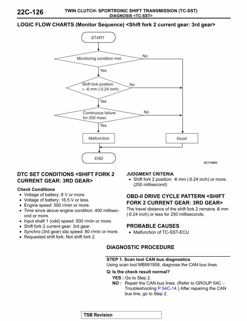
DIAGNOSIS <TC-SST>TWIN CLUTCH- SPORTRONIC SHIFT TRANSMISSION (TC-SST)22C-126
LOGIC FLOW CHARTS (Monitor Sequence) <Shift fork 2 current gear: 3rd gear>
.
DTC SET CONDITIONS <SHIFT FORK 2 CURRENT GEAR: 3RD GEAR>Check Conditions• Voltage of battery: 8 V or more.• Voltage of battery: 16.5 V or less.• Engine speed: 500 r/min or more.• Time since above engine condition: 400 millisec-
ond or more.• Input shaft 1 (odd) speed: 500 r/min or more.• Shift fork 2 current gear: 3rd gear.• Synchro (3rd gear) slip speed: 80 r/min or more.• Requested shift fork: Not shift fork 2.
JUDGMENT CRITERIA• Shift fork 2 position: −6 mm (−0.24 inch) or more.
(250 millisecond).
OBD-II DRIVE CYCLE PATTERN <SHIFT FORK 2 CURRENT GEAR: 3RD GEAR>The travel distance of the shift fork 2 remains −6 mm (−0.24 inch) or less for 250 milliseconds..
PROBABLE CAUSES• Malfunction of TC-SST-ECU
DIAGNOSTIC PROCEDURE
STEP 1. Scan tool CAN bus diagnosticsUsing scan tool MB991958, diagnose the CAN bus lines.Q: Is the check result normal?
YES : Go to Step 2.NO : Repair the CAN bus lines. (Refer to GROUP 54C −
Troubleshooting P.54C-14.) After repairing the CAN bus line, go to Step 2.
AC710683
START
No
GoodMalfunction
END
Monitoring condition met
Continuous failurefor 250 msec
No
Yes
Yes
Yes
NoShift fork position> -6 mm (-0.24 inch)
TSB Revision

DIAGNOSIS <TC-SST>TWIN CLUTCH- SPORTRONIC SHIFT TRANSMISSION (TC-SST) 22C-127
STEP 2. Check whether the DTC is reset.Q: Is DTC No. P1829 set?
YES : Replace the TC-SST assembly. (Refer to P.22C-341.)NO : Intermittent malfunction. (Refer to GROUP 00 − How
to Cope with Intermittent Malfunction P.00-15.)
DTC P182A: Shift Fork Position Sensor 3 System (Voltage low range out)
CAUTION• If there is any problem in the CAN bus lines,
an incorrect diagnostic trouble code may be set. Prior to this diagnosis, diagnose the CAN bus lines.
• Whenever the ECU is replaced, ensure that the CAN bus lines are normal.
.
DIAGNOSTIC FUNCTIONTC-SST-ECU checks that the voltage of the shift fork position sensor 3 is normal..
DESCRIPTIONS OF MONITOR METHODSThe voltage of the shift fork position sensor 3 is too low..
MONITOR EXECUTION• Continuous
.
MONITOR EXECUTION CONDITIONS (OTHER MONITOR AND SENSOR)Other Monitor (There is no temporary DTC stored
in memory for the item monitored below)• P182B: Shift fork position sensor 3 system (Volt-
age high range out)
• P182C: Shift fork position sensor 3 system (Out-put range out)
• P182D: Shift fork position sensor 3 system (Neu-tral)
• P182E: Shift fork position sensor 3 system (Poor performance)
• P1844: Shift fork 3 malfunction• P1852: Shift fork 1 or 2 opposite direction move-
ment• P1855: Shift fork 3 or 4 opposite direction move-
ment• P1858: Even number gear axle interlock• P1876: Gear block 1st• P1877: Gear block 2nd• P1878: Gear block 3rd• P1879: Gear block 4th• P187A: Gear block 5th• P187B: Gear block 6th• P187C: Gear block reverse
Sensor (The sensor below is determined to be normal)
• Not applicable.
TSB Revision

DIAGNOSIS <TC-SST>TWIN CLUTCH- SPORTRONIC SHIFT TRANSMISSION (TC-SST)22C-128
LOGIC FLOW CHARTS (Monitor Sequence)
.
DTC SET CONDITIONSCheck Conditions• Voltage of battery: 8 V or more.• Voltage of battery: 16.5 V or less.
JUDGMENT CRITERIA• Position sensor voltage: 0.128 V or less. (160 mil-
lisecond)
.
OBD-II DRIVE CYCLE PATTERNThe position sensor voltage remains 0.128 V or more for 160 milliseconds..
PROBABLE CAUSES• Malfunction of TC-SST-ECU
DIAGNOSTIC PROCEDURE
STEP 1. Scan tool CAN bus diagnosticsUsing scan tool MB991958, diagnose the CAN bus lines.Q: Is the check result normal?
YES : Go to Step 2.NO : Repair the CAN bus lines. (Refer to GROUP 54C −
Troubleshooting P.54C-14.) After repairing the CAN bus line, go to Step 2.
STEP 2. Check whether the DTC is reset.Q: Is DTC No. P182A set?
YES : Replace the TC-SST assembly. (Refer to P.22C-341.)NO : Intermittent malfunction. (Refer to GROUP 00 − How
to Cope with Intermittent Malfunction P.00-15.)
AC710676
START
No
GoodMalfunction
END
Monitoring condition met
Continuous failurefor 160 msec
No
Yes
Yes
Yes
NoShift fork position< 0.128 V
TSB Revision

DIAGNOSIS <TC-SST>TWIN CLUTCH- SPORTRONIC SHIFT TRANSMISSION (TC-SST) 22C-129
DTC P182B: Shift Fork Position Sensor 3 System (Voltage high range out)
CAUTION• If there is any problem in the CAN bus lines,
an incorrect diagnostic trouble code may be set. Prior to this diagnosis, diagnose the CAN bus lines.
• Whenever the ECU is replaced, ensure that the CAN bus lines are normal.
.
DIAGNOSTIC FUNCTIONTC-SST-ECU checks that the voltage of the shift fork position sensor 3 is normal..
DESCRIPTIONS OF MONITOR METHODSThe voltage of the shift fork position sensor 3 is too high..
MONITOR EXECUTION• Continuous
.
MONITOR EXECUTION CONDITIONS (OTHER MONITOR AND SENSOR)Other Monitor (There is no temporary DTC stored
in memory for the item monitored below)• P182A: Shift fork position sensor 3 system (Volt-
age low range out)
• P182C: Shift fork position sensor 3 system (Out-put range out)
• P182D: Shift fork position sensor 3 system (Neu-tral)
• P182E: Shift fork position sensor 3 system (Poor performance)
• P1844: Shift fork 3 malfunction• P1852: Shift fork 1 or 2 opposite direction move-
ment• P1855: Shift fork 3 or 4 opposite direction move-
ment• P1858: Even number gear axle interlock• P1876: Gear block 1st• P1877: Gear block 2nd• P1878: Gear block 3rd• P1879: Gear block 4th• P187A: Gear block 5th• P187B: Gear block 6th• P187C: Gear block reverse
Sensor (The sensor below is determined to be normal)
• Not applicable.
TSB Revision

DIAGNOSIS <TC-SST>TWIN CLUTCH- SPORTRONIC SHIFT TRANSMISSION (TC-SST)22C-130
LOGIC FLOW CHARTS (Monitor Sequence)
.
DTC SET CONDITIONSCheck Conditions• Voltage of battery: 8 V or more.• Voltage of battery: 16.5 V or less.
JUDGMENT CRITERIA• Position sensor voltage: 3.008 V or more. (160
millisecond)
.
OBD-II DRIVE CYCLE PATTERNThe position sensor voltage remains 3.008 V or less for 160 milliseconds..
PROBABLE CAUSES• Malfunction of TC-SST-ECU
DIAGNOSTIC PROCEDURE
STEP 1. Scan tool CAN bus diagnosticsUsing scan tool MB991958, diagnose the CAN bus lines.Q: Is the check result normal?
YES : Go to Step 2.NO : Repair the CAN bus lines. (Refer to GROUP 54C −
Troubleshooting P.54C-14.) After repairing the CAN bus line, go to Step 2.
STEP 2. Check whether the DTC is reset.Q: Is DTC No. P182B set?
YES : Replace the TC-SST assembly. (Refer to P.22C-341.)NO : Intermittent malfunction. (Refer to GROUP 00 − How
to Cope with Intermittent Malfunction P.00-15.)
AC710680
START
No
GoodMalfunction
END
Monitoring condition met
Continuous failurefor 160 msec
No
Yes
Yes
Yes
NoShift fork position> 3.008 V
TSB Revision
DIAGNOSIS <TC-SST>TWIN CLUTCH- SPORTRONIC SHIFT TRANSMISSION (TC-SST) 22C-131
DTC P182C: Shift Fork Position Sensor 3 System (Output range out)
CAUTION• If there is any problem in the CAN bus lines,
an incorrect diagnostic trouble code may be set. Prior to this diagnosis, diagnose the CAN bus lines.
• Whenever the ECU is replaced, ensure that the CAN bus lines are normal.
.
DIAGNOSTIC FUNCTIONTC-SST-ECU checks that the output of the shift fork position sensor 3 is normal..
DESCRIPTIONS OF MONITOR METHODSThe output of the shift fork position sensor 3 is deter-mined to be abnormal..
MONITOR EXECUTION• Continuous
.
MONITOR EXECUTION CONDITIONS (OTHER MONITOR AND SENSOR)Other Monitor (There is no temporary DTC stored
in memory for the item monitored below)• P182A: Shift fork position sensor 3 system (Volt-
age low range out)
• P182B: Shift fork position sensor 3 system (Volt-age high range out)
• P182D: Shift fork position sensor 3 system (Neu-tral)
• P182E: Shift fork position sensor 3 system (Poor performance)
• P1844: Shift fork 3 malfunction• P1852: Shift fork 1 or 2 opposite direction move-
ment• P1855: Shift fork 3 or 4 opposite direction move-
ment• P1858: Even number gear axle interlock• P1876: Gear block 1st• P1877: Gear block 2nd• P1878: Gear block 3rd• P1879: Gear block 4th• P187A: Gear block 5th• P187B: Gear block 6th• P187C: Gear block reverse
Sensor (The sensor below is determined to be normal)
• Not applicable.
TSB Revision

DIAGNOSIS <TC-SST>TWIN CLUTCH- SPORTRONIC SHIFT TRANSMISSION (TC-SST)22C-132
LOGIC FLOW CHARTS (Monitor Sequence)
.
DTC SET CONDITIONSCheck Conditions• Voltage of battery: 8 V or more.• Voltage of battery: 16.5 V or less.• Engine speed: 500 r/min or more.• Time since above engine condition: 400 millisec-
ond or more.• Shift system status: Gear change mode (during
shift fork moving).
JUDGMENT CRITERIA• Shift fork 3 position counter (digitized sensor
value): −500 counts or less, shift fork 3 position counter (digitized sensor value): 500 counts or more. (180 millisecond)
•.
OBD-II DRIVE CYCLE PATTERNThe status with the shift fork 3 position counter (digi-tized sensor value) −500 counts or more, or with the shift fork 3 position counter (digitized sensor value) 500 counts or less continues for 180 milliseconds..
PROBABLE CAUSES• Malfunction of TC-SST-ECU
AC710681
START
No
GoodMalfunction
END
Continuous failurefor 180 msec
No
Yes
Yes
Yes
No
NoShift fork positioncounter < -500
Yes
Shift fork positioncounter > 500
Monitoring condition met
TSB Revision

DIAGNOSIS <TC-SST>TWIN CLUTCH- SPORTRONIC SHIFT TRANSMISSION (TC-SST) 22C-133
DIAGNOSTIC PROCEDURE
STEP 1. Scan tool CAN bus diagnosticsUsing scan tool MB991958, diagnose the CAN bus lines.Q: Is the check result normal?
YES : Go to Step 2.NO : Repair the CAN bus lines. (Refer to GROUP 54C −
Troubleshooting P.54C-14.) After repairing the CAN bus line, go to Step 2.
STEP 2. Check whether the DTC is reset.Q: Is DTC No. P182C set?
YES : Replace the TC-SST assembly. (Refer to P.22C-341.)NO : Intermittent malfunction. (Refer to GROUP 00 − How
to Cope with Intermittent Malfunction P.00-15.)
DTC P182D: Shift Fork Position Sensor 3 System (Neutral)
CAUTION• If there is any problem in the CAN bus lines,
an incorrect diagnostic trouble code may be set. Prior to this diagnosis, diagnose the CAN bus lines.
• Whenever the ECU is replaced, ensure that the CAN bus lines are normal.
.
DIAGNOSTIC FUNCTIONTC-SST-ECU checks that the shift fork position sen-sor 3 is normal..
DESCRIPTIONS OF MONITOR METHODSThe shift fork position sensor 3 is determined to be abnormal..
MONITOR EXECUTION• Continuous
.
MONITOR EXECUTION CONDITIONS (OTHER MONITOR AND SENSOR)Other Monitor (There is no temporary DTC stored
in memory for the item monitored below)• P182A: Shift fork position sensor 3 system (Volt-
age low range out)
• P182B: Shift fork position sensor 3 system (Volt-age high range out)
• P182C: Shift fork position sensor 3 system (Out-put range out)
• P182E: Shift fork position sensor 3 system (Poor performance)
• P1844: Shift fork 3 malfunction• P1852: Shift fork 1 or 2 opposite direction move-
ment• P1855: Shift fork 3 or 4 opposite direction move-
ment• P1858: Even number gear axle interlock• P1876: Gear block 1st• P1877: Gear block 2nd• P1878: Gear block 3rd• P1879: Gear block 4th• P187A: Gear block 5th• P187B: Gear block 6th• P187C: Gear block reverse
Sensor (The sensor below is determined to be normal)
• Not applicable.
TSB Revision

DIAGNOSIS <TC-SST>TWIN CLUTCH- SPORTRONIC SHIFT TRANSMISSION (TC-SST)22C-134
LOGIC FLOW CHARTS (Monitor Sequence)
.
DTC SET CONDITIONSCheck Conditions• Voltage of battery: 8 V or more.• Voltage of battery: 16.5 V or less.• Engine speed: 500 r/min or more.• Time since above engine condition: 400 millisec-
ond or more.• Input shaft 1 (odd) speed: 500 r/min or more.• Input shaft 2 (even) speed: 500 r/min or more.• Shift fork 3 position: Neutral.• Input shaft 1 (odd) gear: Engaged.
• Engine speed − input shaft 1 speed: 50 r/min or less.
JUDGMENT CRITERIA• Calculated speed: 40 r/min or less. (500 millisec-
ond).
OBD-II DRIVE CYCLE PATTERNThe calculated speed remains 40 r/min or more for 500 milliseconds.
DIAGNOSTIC PROCEDURE
STEP 1. Scan tool CAN bus diagnosticsUsing scan tool MB991958, diagnose the CAN bus lines.Q: Is the check result normal?
YES : Go to Step 2.NO : Repair the CAN bus lines. (Refer to GROUP 54C −
Troubleshooting P.54C-14.) After repairing the CAN bus line, go to Step 2.
AC711383
START
No
GoodMalfunction
END
Monitoring condition met
Continuous failurefor 500 msec
No
Yes
Yes
Yes
NoCalculated input shaft speed
TSB Revision

DIAGNOSIS <TC-SST>TWIN CLUTCH- SPORTRONIC SHIFT TRANSMISSION (TC-SST) 22C-135
STEP 2. Check whether the DTC is reset.Q: Is DTC No. P182D set?
YES : Replace the TC-SST assembly. (Refer to P.22C-341.)NO : Intermittent malfunction. (Refer to GROUP 00 − How
to Cope with Intermittent Malfunction P.00-15.)
DTC P182E: Shift Fork Position Sensor 3 System (Poor performance)
CAUTION• If there is any problem in the CAN bus lines,
an incorrect diagnostic trouble code may be set. Prior to this diagnosis, diagnose the CAN bus lines.
• Whenever the ECU is replaced, ensure that the CAN bus lines are normal.
.
DIAGNOSTIC FUNCTIONTC-SST-ECU checks that the shift fork position sen-sor 3 is normal..
DESCRIPTIONS OF MONITOR METHODSThe shift fork position sensor 3 is determined to be abnormal..
MONITOR EXECUTION• Continuous
.
MONITOR EXECUTION CONDITIONS (OTHER MONITOR AND SENSOR)Other Monitor (There is no temporary DTC stored
in memory for the item monitored below)• P182A: Shift fork position sensor 3 system (Volt-
age low range out)
• P182B: Shift fork position sensor 3 system (Volt-age high range out)
• P182C: Shift fork position sensor 3 system (Out-put range out)
• P182D: Shift fork position sensor 3 system (Neu-tral)
• P1844: Shift fork 3 malfunction• P1852: Shift fork 1 or 2 opposite direction move-
ment• P1855: Shift fork 3 or 4 opposite direction move-
ment• P1858: Even number gear axle interlock• P1876: Gear block 1st• P1877: Gear block 2nd• P1878: Gear block 3rd• P1879: Gear block 4th• P187A: Gear block 5th• P187B: Gear block 6th• P187C: Gear block reverse
Sensor (The sensor below is determined to be normal)
• Not applicable.
TSB Revision

DIAGNOSIS <TC-SST>TWIN CLUTCH- SPORTRONIC SHIFT TRANSMISSION (TC-SST)22C-136
LOGIC FLOW CHARTS (Monitor Sequence)
.
DTC SET CONDITIONSCheck Conditions• Voltage of battery: 8 V or more.• Voltage of battery: 16.5 V or less.• Engine speed: 500 r/min or more.• Time since above engine condition: 400 millisec-
ond or more.• Input shaft 2 (even) speed: 500 r/min or more.• Shift fork 3 current gear: 6th gear.• Synchro (6th gear) slip speed: 80 r/min or more.• Requested shift fork: Not shift fork 3.
JUDGMENT CRITERIA• Shift fork 3 position: −6 mm (−0.24 inch) or more.
(250 millisecond).
OBD-II DRIVE CYCLE PATTERN The travel distance of the shift fork 3 remains −6 mm (−0.24 inch) or less for 250 milliseconds..
PROBABLE CAUSES• Malfunction of TC-SST-ECU
DIAGNOSTIC PROCEDURE
STEP 1. Scan tool CAN bus diagnosticsUsing scan tool MB991958, diagnose the CAN bus lines.Q: Is the check result normal?
YES : Go to Step 2.NO : Repair the CAN bus lines. (Refer to GROUP 54C −
Troubleshooting P.54C-14.) After repairing the CAN bus line, go to Step 2.
AC710683
START
No
GoodMalfunction
END
Monitoring condition met
Continuous failurefor 250 msec
No
Yes
Yes
Yes
NoShift fork position> -6 mm (-0.24 inch)
TSB Revision

DIAGNOSIS <TC-SST>TWIN CLUTCH- SPORTRONIC SHIFT TRANSMISSION (TC-SST) 22C-137
STEP 2. Check whether the DTC is reset.Q: Is DTC No. P182E set?
YES : Replace the TC-SST assembly. (Refer to P.22C-341.)NO : Intermittent malfunction. (Refer to GROUP 00 − How
to Cope with Intermittent Malfunction P.00-15.)
DTC P1831: Shift Fork Position Sensor 4 System (Voltage low range out)
CAUTION• If there is any problem in the CAN bus lines,
an incorrect diagnostic trouble code may be set. Prior to this diagnosis, diagnose the CAN bus lines.
• Whenever the ECU is replaced, ensure that the CAN bus lines are normal.
.
DIAGNOSTIC FUNCTIONTC-SST-ECU checks that the voltage of the shift fork position sensor 4 is normal..
DESCRIPTIONS OF MONITOR METHODSThe voltage of the shift fork position sensor 4 is too low..
MONITOR EXECUTION• Continuous
.
MONITOR EXECUTION CONDITIONS (OTHER MONITOR AND SENSOR)Other Monitor (There is no temporary DTC stored
in memory for the item monitored below)• P1832: Shift fork position sensor 4 system (Volt-
age high range out)
• P1833: Shift fork position sensor 4 system (Out-put range out)
• P1834: Shift fork position sensor 4 system (Neu-tral)
• P1835: Shift fork position sensor 4 system (Poor performance)
• P184B: Shift fork 4 malfunction• P1852: Shift fork 1 or 2 opposite direction move-
ment• P1855: Shift fork 3 or 4 opposite direction move-
ment• P1858: Even number gear axle interlock• P1876: Gear block 1st• P1877: Gear block 2nd• P1878: Gear block 3rd• P1879: Gear block 4th• P187A: Gear block 5th• P187B: Gear block 6th• P187C: Gear block reverse
Sensor (The sensor below is determined to be normal)
• Not applicable.
TSB Revision

DIAGNOSIS <TC-SST>TWIN CLUTCH- SPORTRONIC SHIFT TRANSMISSION (TC-SST)22C-138
LOGIC FLOW CHARTS (Monitor Sequence)
.
DTC SET CONDITIONSCheck Conditions• Voltage of battery: 8 V or more.• Voltage of battery: 16.5 V or less.
JUDGMENT CRITERIA• Position sensor voltage: 0.128 V or less. (160 mil-
lisecond)
.
OBD-II DRIVE CYCLE PATTERNThe position sensor voltage remains 0.128 V or more for 160 milliseconds..
PROBABLE CAUSES• Malfunction of TC-SST-ECU
DIAGNOSTIC PROCEDURE
STEP 1. Scan tool CAN bus diagnosticsUsing scan tool MB991958, diagnose the CAN bus lines.Q: Is the check result normal?
YES : Go to Step 2.NO : Repair the CAN bus lines. (Refer to GROUP 54C −
Troubleshooting P.54C-14.) After repairing the CAN bus line, go to Step 2.
STEP 2. Check whether the DTC is reset.Q: Is DTC No. P1831 set?
YES : Replace the TC-SST assembly. (Refer to P.22C-341.)NO : Intermittent malfunction. (Refer to GROUP 00 − How
to Cope with Intermittent Malfunction P.00-15.)
AC710676
START
No
GoodMalfunction
END
Monitoring condition met
Continuous failurefor 160 msec
No
Yes
Yes
Yes
NoShift fork position< 0.128 V
TSB Revision

DIAGNOSIS <TC-SST>TWIN CLUTCH- SPORTRONIC SHIFT TRANSMISSION (TC-SST) 22C-139
DTC P1832: Shift Fork Position Sensor 4 System (Voltage high range out)
CAUTION• If there is any problem in the CAN bus lines,
an incorrect diagnostic trouble code may be set. Prior to this diagnosis, diagnose the CAN bus lines.
• Whenever the ECU is replaced, ensure that the CAN bus lines are normal.
.
DIAGNOSTIC FUNCTIONTC-SST-ECU checks that the voltage of the shift fork position sensor 4 is normal..
DESCRIPTIONS OF MONITOR METHODSThe voltage of the shift fork position sensor 4 is too high..
MONITOR EXECUTION• Continuous
.
MONITOR EXECUTION CONDITIONS (OTHER MONITOR AND SENSOR)Other Monitor (There is no temporary DTC stored
in memory for the item monitored below)• P1831: Shift fork position sensor 4 system (Volt-
age low range out)
• P1833: Shift fork position sensor 4 system (Out-put range out)
• P1834: Shift fork position sensor 4 system (Neu-tral)
• P1835: Shift fork position sensor 4 system (Poor performance)
• P184B: Shift fork 4 malfunction• P1852: Shift fork 1 or 2 opposite direction move-
ment• P1855: Shift fork 3 or 4 opposite direction move-
ment• P1858: Even number gear axle interlock• P1876: Gear block 1st• P1877: Gear block 2nd• P1878: Gear block 3rd• P1879: Gear block 4th• P187A: Gear block 5th• P187B: Gear block 6th• P187C: Gear block reverse
Sensor (The sensor below is determined to be normal)
• Not applicable.
TSB Revision

DIAGNOSIS <TC-SST>TWIN CLUTCH- SPORTRONIC SHIFT TRANSMISSION (TC-SST)22C-140
LOGIC FLOW CHARTS (Monitor Sequence)
.
DTC SET CONDITIONSCheck Conditions• Voltage of battery: 8 V or more.• Voltage of battery: 16.5 V or less.
JUDGMENT CRITERIA• Position sensor voltage: 3.008 V or more. (160
millisecond)
.
OBD-II DRIVE CYCLE PATTERNThe position sensor voltage remains 3.008 V or less for 160 milliseconds..
PROBABLE CAUSES• Malfunction of TC-SST-ECU
DIAGNOSTIC PROCEDURE
STEP 1. Scan tool CAN bus diagnosticsUsing scan tool MB991958, diagnose the CAN bus lines.Q: Is the check result normal?
YES : Go to Step 2.NO : Repair the CAN bus lines. (Refer to GROUP 54C −
Troubleshooting P.54C-14.) After repairing the CAN bus line, go to Step 2.
STEP 2. Check whether the DTC is reset.Q: Is DTC No. P1832 set?
YES : Replace the TC-SST assembly. (Refer to P.22C-341.)NO : Intermittent malfunction. (Refer to GROUP 00 − How
to Cope with Intermittent Malfunction P.00-15.)
AC710680
START
No
GoodMalfunction
END
Monitoring condition met
Continuous failurefor 160 msec
No
Yes
Yes
Yes
NoShift fork position> 3.008 V
TSB Revision

DIAGNOSIS <TC-SST>TWIN CLUTCH- SPORTRONIC SHIFT TRANSMISSION (TC-SST) 22C-141
DTC P1833: Shift Fork Position Sensor 4 System (Output range out)
CAUTION• If there is any problem in the CAN bus lines,
an incorrect diagnostic trouble code may be set. Prior to this diagnosis, diagnose the CAN bus lines.
• Whenever the ECU is replaced, ensure that the CAN bus lines are normal.
.
DIAGNOSTIC FUNCTIONTC-SST-ECU checks that the output of the shift fork position sensor 4 is normal..
DESCRIPTIONS OF MONITOR METHODSThe output of the shift fork position sensor 4 is deter-mined to be abnormal..
MONITOR EXECUTION• Continuous
.
MONITOR EXECUTION CONDITIONS (OTHER MONITOR AND SENSOR)Other Monitor (There is no temporary DTC stored
in memory for the item monitored below)• P1831: Shift fork position sensor 4 system (Volt-
age low range out)
• P1832: Shift fork position sensor 4 system (Volt-age high range out)
• P1834: Shift fork position sensor 4 system (Neu-tral)
• P1835: Shift fork position sensor 4 system (Poor performance)
• P184B: Shift fork 4 malfunction• P1852: Shift fork 1 or 2 opposite direction move-
ment• P1855: Shift fork 3 or 4 opposite direction move-
ment• P1858: Even number gear axle interlock• P1876: Gear block 1st• P1877: Gear block 2nd• P1878: Gear block 3rd• P1879: Gear block 4th• P187A: Gear block 5th• P187B: Gear block 6th• P187C: Gear block reverse
Sensor (The sensor below is determined to be normal)
• Not applicable.
TSB Revision

DIAGNOSIS <TC-SST>TWIN CLUTCH- SPORTRONIC SHIFT TRANSMISSION (TC-SST)22C-142
LOGIC FLOW CHARTS (Monitor Sequence)
.
DTC SET CONDITIONSCheck Conditions• Voltage of battery: 8 V or more.• Voltage of battery: 16.5 V or less.• Engine speed: 500 r/min or more.• Time since above engine condition: 400 millisec-
ond or more.• Shift system status: Gear change mode (during
shift fork moving).
JUDGMENT CRITERIA• Shift fork 4 position counter (digitized sensor
value): −500 counts or less, or shift fork 4 position counter (digitized sensor value): 500 counts or more. (180 millisecond)
.
OBD-II DRIVE CYCLE PATTERNThe status with the shift fork 4 position counter (digi-tized sensor value) −500 counts or more, or with the shift fork 4 position counter (digitized sensor value) 500 counts or less continues for 180 milliseconds..
PROBABLE CAUSES• Malfunction of TC-SST-ECU
AC710681
START
No
GoodMalfunction
END
Continuous failurefor 180 msec
No
Yes
Yes
Yes
No
NoShift fork positioncounter < -500
Yes
Shift fork positioncounter > 500
Monitoring condition met
TSB Revision

DIAGNOSIS <TC-SST>TWIN CLUTCH- SPORTRONIC SHIFT TRANSMISSION (TC-SST) 22C-143
DIAGNOSTIC PROCEDURE
STEP 1. Scan tool CAN bus diagnosticsUsing scan tool MB991958, diagnose the CAN bus lines.Q: Is the check result normal?
YES : Go to Step 2.NO : Repair the CAN bus lines. (Refer to GROUP 54C −
Troubleshooting P.54C-14.) After repairing the CAN bus line, go to Step 2.
STEP 2. Check whether the DTC is reset.Q: Is DTC No. P1833 set?
YES : Replace the TC-SST assembly. (Refer to P.22C-341.)NO : Intermittent malfunction. (Refer to GROUP 00 − How
to Cope with Intermittent Malfunction P.00-15.)
DTC P1834: Shift Fork Position Sensor 4 System (Neutral)
CAUTION• If there is any problem in the CAN bus lines,
an incorrect diagnostic trouble code may be set. Prior to this diagnosis, diagnose the CAN bus lines.
• Whenever the ECU is replaced, ensure that the CAN bus lines are normal.
.
DIAGNOSTIC FUNCTIONTC-SST-ECU checks that the shift fork position sen-sor 4 is normal..
DESCRIPTIONS OF MONITOR METHODSThe shift fork position sensor 4 is determined to be abnormal..
MONITOR EXECUTION• Continuous
.
MONITOR EXECUTION CONDITIONS (OTHER MONITOR AND SENSOR)Other Monitor (There is no temporary DTC stored
in memory for the item monitored below)• P1831: Shift fork position sensor 4 system (Volt-
age low range out)
• P1832: Shift fork position sensor 4 system (Volt-age high range out)
• P1833: Shift fork position sensor 4 system (Out-put range out)
• P1835: Shift fork position sensor 4 system (Poor performance)
• P184B: Shift fork 4 malfunction• P1852: Shift fork 1 or 2 opposite direction move-
ment• P1855: Shift fork 3 or 4 opposite direction move-
ment• P1858: Even number gear axle interlock• P1876: Gear block 1st• P1877: Gear block 2nd• P1878: Gear block 3rd• P1879: Gear block 4th• P187A: Gear block 5th• P187B: Gear block 6th• P187C: Gear block reverse
Sensor (The sensor below is determined to be normal)
• Not applicable.
TSB Revision

DIAGNOSIS <TC-SST>TWIN CLUTCH- SPORTRONIC SHIFT TRANSMISSION (TC-SST)22C-144
LOGIC FLOW CHARTS (Monitor Sequence)
.
DTC SET CONDITIONSCheck Conditions• Voltage of battery: 8 V or more.• Voltage of battery: 16.5 V or less.• Engine speed: 500 r/min or more.• Time since above engine condition: 400 millisec-
ond or more.• Input shaft 1 (odd) speed: 500 r/min or more.• Input shaft 2 (even) speed: 500 r/min or more.• Shift fork 4 position: Neutral.• Input shaft 1 (odd) gear: Engaged.
• Engine speed − input shaft 1 speed: 50 r/min or less.
JUDGMENT CRITERIA• Calculated speed: 40 r/min or less. (500 millisec-
ond).
OBD-II DRIVE CYCLE PATTERNThe calculated speed remains 40 r/min or more for 500 milliseconds.
DIAGNOSTIC PROCEDURE
STEP 1. Scan tool CAN bus diagnosticsUsing scan tool MB991958, diagnose the CAN bus lines.Q: Is the check result normal?
YES : Go to Step 2.NO : Repair the CAN bus lines. (Refer to GROUP 54C −
Troubleshooting P.54C-14.) After repairing the CAN bus line, go to Step 2.
AC711383
START
No
GoodMalfunction
END
Monitoring condition met
Continuous failurefor 500 msec
No
Yes
Yes
Yes
NoCalculated input shaft speed
TSB Revision

DIAGNOSIS <TC-SST>TWIN CLUTCH- SPORTRONIC SHIFT TRANSMISSION (TC-SST) 22C-145
STEP 2. Check whether the DTC is reset.Q: Is DTC No. P1834 set?
YES : Replace the TC-SST assembly. (Refer to P.22C-341.)NO : Intermittent malfunction. (Refer to GROUP 00 − How
to Cope with Intermittent Malfunction P.00-15.)
DTC P1835: Shift Fork Position Sensor 4 System (Poor performance)
CAUTION• If there is any problem in the CAN bus lines,
an incorrect diagnostic trouble code may be set. Prior to this diagnosis, diagnose the CAN bus lines.
• Whenever the ECU is replaced, ensure that the CAN bus lines are normal.
.
DIAGNOSTIC FUNCTIONTC-SST-ECU checks that the shift fork position sen-sor 4 is normal..
DESCRIPTIONS OF MONITOR METHODSThe shift fork position sensor 4 is determined to be abnormal..
MONITOR EXECUTION• Continuous
.
MONITOR EXECUTION CONDITIONS (OTHER MONITOR AND SENSOR)Other Monitor (There is no temporary DTC stored
in memory for the item monitored below)• P1831: Shift fork position sensor 4 system (Volt-
age low range out)
• P1832: Shift fork position sensor 4 system (Volt-age high range out)
• P1833: Shift fork position sensor 4 system (Out-put range out)
• P1834: Shift fork position sensor 4 system (Neu-tral)
• P184B: Shift fork 4 malfunction• P1852: Shift fork 1 or 2 opposite direction move-
ment• P1855: Shift fork 3 or 4 opposite direction move-
ment• P1858: Even number gear axle interlock• P1876: Gear block 1st• P1877: Gear block 2nd• P1878: Gear block 3rd• P1879: Gear block 4th• P187A: Gear block 5th• P187B: Gear block 6th• P187C: Gear block reverse
Sensor (The sensor below is determined to be normal)
• Not applicable.
TSB Revision

DIAGNOSIS <TC-SST>TWIN CLUTCH- SPORTRONIC SHIFT TRANSMISSION (TC-SST)22C-146
LOGIC FLOW CHARTS (Monitor Sequence) <Shift fork 4 current gear: 4th gear>
.
DTC SET CONDITIONS <SHIFT FORK 4 CURRENT GEAR: 4TH GEAR>Check Conditions• Voltage of battery: 8 V or more.• Voltage of battery: 16.5 V or less.• Engine speed: 500 r/min or more.• Time since above engine condition: 400 millisec-
ond or more.• Input shaft 2 (even) speed: 500 r/min or more.• Shift fork 4 current gear: 4th gear.• Synchro (2nd gear) slip speed: 80 r/min or more.
• Requested shift fork: Not shift fork 4.
JUDGMENT CRITERIA• Shift fork 4 position: 6 mm (0.24 inch) or less.
(250 millisecond).
OBD-II DRIVE CYCLE PATTERN <SHIFT FORK 2 CURRENT GEAR: 4TH GEAR>The travel distance of the shift fork 4 remains 6 mm (0.24 inch) or more for 250 milliseconds..
AC710682
START
No
GoodMalfunction
END
Monitoring condition met
Continuous failurefor 250 msec
No
Yes
Yes
Yes
NoShift fork position< 6 mm (0.24 inch)
TSB Revision

DIAGNOSIS <TC-SST>TWIN CLUTCH- SPORTRONIC SHIFT TRANSMISSION (TC-SST) 22C-147
LOGIC FLOW CHARTS (Monitor Sequence) <Shift fork 4 current gear: 2nd gear>
.
DTC SET CONDITIONS <SHIFT FORK 4 CURRENT GEAR: 2ND GEAR>Check Conditions• Voltage of battery: 8 volts or more.• Voltage of battery: 16.5 volts or less.• Engine speed: 500 r/min or more.• Time since above engine condition: 400 millisec-
ond or more.• Input shaft 2 (even) speed: 500 r/min or more.• Shift fork 4 current gear: 2nd gear.• Synchro (4th gear) slip speed: 80 r/min or more.• Requested shift fork: not shift fork 4.
JUDGMENT CRITERIA• Shift fork 4 position: −6 mm (−0.24 in) or more.
(250 millisecond).
OBD-II DRIVE CYCLE PATTERN <SHIFT FORK 2 CURRENT GEAR: 3RD GEAR>The travel distance of the shift fork 4 remains −6 mm (−0.24 inch) or less for 250 milliseconds..
PROBABLE CAUSES• Malfunction of TC-SST-ECU
DIAGNOSTIC PROCEDURE
STEP 1. Scan tool CAN bus diagnosticsUsing scan tool MB991958, diagnose the CAN bus lines.Q: Is the check result normal?
YES : Go to Step 2.NO : Repair the CAN bus lines. (Refer to GROUP 54C −
Troubleshooting P.54C-14.) After repairing the CAN bus line, go to Step 2.
AC710683
START
No
GoodMalfunction
END
Monitoring condition met
Continuous failurefor 250 msec
No
Yes
Yes
Yes
NoShift fork position> -6 mm (-0.24 inch)
TSB Revision

DIAGNOSIS <TC-SST>TWIN CLUTCH- SPORTRONIC SHIFT TRANSMISSION (TC-SST)22C-148
STEP 2. Check whether the DTC is reset.Q: Is DTC No. P1835 set?
YES : Replace the TC-SST assembly. (Refer to P.22C-341.)NO : Intermittent malfunction. (Refer to GROUP 00 − How
to Cope with Intermittent Malfunction P.00-15.)
DTC P1836: Shift Fork 1 Malfunction
CAUTION• If there is any problem in the CAN bus lines,
an incorrect diagnostic trouble code may be set. Prior to this diagnosis, diagnose the CAN bus lines.
• Whenever the ECU is replaced, ensure that the CAN bus lines are normal.
.
DIAGNOSTIC FUNCTIONTC-SST-ECU checks that the movement of the shift fork 1 is normal..
DESCRIPTIONS OF MONITOR METHODSThe movement of the shift fork 1 is determined to be abnormal.
.
MONITOR EXECUTION• Continuous
.
MONITOR EXECUTION CONDITIONS (OTHER MONITOR AND SENSOR)Other Monitor (There is no temporary DTC stored
in memory for the item monitored below)• P183D: Shift fork 2 malfunction• P1844: Shift fork 3 malfunction
Sensor (The sensor below is determined to be normal)
• Not applicable.
LOGIC FLOW CHARTS (Monitor Sequence) <Functional check - blocked>
.
AC710675
START
No
GoodMalfunction
END
Yes
Malfunction criteria met
Yes
Monitoring condition met
No
TSB Revision

DIAGNOSIS <TC-SST>TWIN CLUTCH- SPORTRONIC SHIFT TRANSMISSION (TC-SST) 22C-149
DTC SET CONDITIONS <FUNCTIONAL CHECK - BLOCKED>Check Conditions• Voltage of battery: 8 V or more.• Voltage of battery: 16.5 V or less.• Engine speed: 500 r/min or more.• Time since above engine condition: 400 millisec-
ond or more.• Common high side 1 voltage: 2.5 V or more.• Common high side 3 voltage: 2.5 V or more.
JUDGMENT CRITERIA•
•
• Shift fork operation time: Shift fork operation time (threshold value) or more. (immediately)
• Shift fork operation time (threshold value): Equal the maximum allowed time x Coefficient. (imme-diately)
.
OBD-II DRIVE CYCLE PATTERN <FUNCTIONAL CHECK - BLOCKED>The shift fork operation time is threshold value or less..AC710827
Max
imum
allo
wed
tim
e (s
ec)
25
20
15
10
5
-40 -20 0 20 120
Fluid temperature [˚C (˚F)]AB
1 Until completion of initial shift fork action2 After completion of initial shift fork action
(-40) (-4) (32) (68) (248)
AC710826
1.5
4,000 8,000 16,000
Line pressure (mbar)
1.25
1
Coefficient
AB
TSB Revision

DIAGNOSIS <TC-SST>TWIN CLUTCH- SPORTRONIC SHIFT TRANSMISSION (TC-SST)22C-150
LOGIC FLOW CHARTS (Monitor Sequence) <Functional check - 1st gear>
.
DTC SET CONDITIONS <FUNCTIONAL CHECK - 1ST GEAR>Check Conditions• Voltage of battery: 8 V or more.• Voltage of battery: 16.5 V or less.• Engine speed: 500 r/min or more.• Time since above engine condition: 400 millisec-
ond or more.• Shift fork 1 current gear: 1st gear.
JUDGMENT CRITERIA• Shift fork position: 6 mm (0.24 inch) or less, and
input shaft 1 (odd) speed: 500 r/min or more, or synchro (1st gear) slip speed: 80 r/min or more. (400 millisecond)
.
OBD-II DRIVE CYCLE PATTERN <FUNCTIONAL CHECK - 1ST GEAR>The status with the shift fork position 6 mm (0.24 inch) or more and with the input shaft 1 (odd) speed 500 r/min or less, or with the synchro (1st gear) slip speed 80 r/min or less continues for 400 millisec-onds..
AC710684
START
No
GoodMalfunction
END
Continuous failurefor 400 msec
No
Yes
Yes
Yes
No
NoInput shaft 1 speed> 500 r/min
Yes
Synchro slip speed> 80 r/min
Monitoring condition met
Yes
NoShift fork 1 position< 6 mm (0.24 inch)
TSB Revision

DIAGNOSIS <TC-SST>TWIN CLUTCH- SPORTRONIC SHIFT TRANSMISSION (TC-SST) 22C-151
LOGIC FLOW CHARTS (Monitor Sequence) <Functional check - Reverse gear>
.
DTC SET CONDITIONS <FUNCTIONAL CHECK - REVERSE GEAR>Check Conditions• Voltage of battery: 8 V or more.• Voltage of battery: 16.5 V or less.• Engine speed: 500 r/min or more.• Time since above engine condition: 400 millisec-
ond or more.• Shift fork 1 current gear: Reverse gear.
JUDGMENT CRITERIA• Shift fork position: −6 mm (−0.24 inch) or more,
and input shaft 1 (odd) speed: 500 r/min or more, or synchro (Reverse gear) slip speed: 80 r/min or more. (400 millisecond)
.
OBD-II DRIVE CYCLE PATTERN <FUNCTIONAL CHECK - REVERSE GEAR>The status with the shift fork position −6 mm (−0.24 inch) or less and with the input shaft 1 (odd) speed 500 r/min or less, or with the synchro (reverse gear) slip speed 80 r/min or less continues for 400 millisec-onds.
AC710685
START
No
GoodMalfunction
END
Continuous failurefor 400 msec
No
Yes
Yes
Yes
No
NoInput shaft 1 speed> 500 r/min
Yes
Synchro slip speed> 80 r/min
Monitoring condition met
Yes
NoShift fork 1 position> -6 mm (-0.24 inch)
TSB Revision

DIAGNOSIS <TC-SST>TWIN CLUTCH- SPORTRONIC SHIFT TRANSMISSION (TC-SST)22C-152
.
LOGIC FLOW CHARTS (Monitor Sequence) <Functional check - Neutral>
.
DTC SET CONDITIONS <FUNCTIONAL CHECK - NEUTRAL>Check Conditions• Voltage of battery: 8 V or more.• Voltage of battery: 16.5 V or less.• Engine speed: 500 r/min or more.• Time since above engine condition: 400 millisec-
ond or more.• Shift fork 1 current gear: Neutral.
JUDGMENT CRITERIA• Shift fork position: 1.8 mm (0.071 inch) or more.
(250 millisecond).
OBD-II DRIVE CYCLE PATTERN <FUNCTIONAL CHECK - NEUTRAL>The shift fork position remains 1.8 mm (0.071 inch) or less for 250 milliseconds..
AC710686
START
No
GoodMalfunction
END
Continuous failurefor 250 msec
No
Yes
Yes
Monitoring condition met
Yes
No|Shift fork position|> 1.8 mm (0.071 inch)
TSB Revision

DIAGNOSIS <TC-SST>TWIN CLUTCH- SPORTRONIC SHIFT TRANSMISSION (TC-SST) 22C-153
LOGIC FLOW CHARTS (Monitor Sequence) <Functional check - Shift fork 1 requested but shift fork 3 movement>
.
AC710687
START
No
GoodMalfunction
END
No
Yes
Yes
Yes
No
No
Yes
Monitoring condition met
Yes
No
Yes
Shift fork 3 positionneutral position
No
Yes
No
|Initialized fork position -shift fork 1 position| < 2.5 mm (0.098 inch)
Shift fork 3 position6th gear side
Shift fork 3 position> -6 mm (-0.24 inch)
Continuous failurefor 200 msec
|Shift fork 3 position|> 1.8 mm (0.071 inch)
TSB Revision

DIAGNOSIS <TC-SST>TWIN CLUTCH- SPORTRONIC SHIFT TRANSMISSION (TC-SST)22C-154
DTC SET CONDITIONS <FUNCTIONAL CHECK - SHIFT FORK 1 REQUESTED BUT SHIFT FORK 3 MOVEMENT>Check Conditions• Voltage of battery: 8 V or more.• Voltage of battery: 16.5 V or less.• Engine speed: 500 r/min or more.• Time since above engine condition: 400 millisec-
ond or more.• Requested shift fork: Shift fork 1.
JUDGMENT CRITERIA• Shift fork 3 position: −6 mm (−0.24 inch) [6th gear
side] or more, or 1.8 mm (0.071 inch) [neutral position] or more, and initialized fork position − shift fork 1 position: 2.5 mm (0.098 inch) or less. (200 millisecond)
.
OBD-II DRIVE CYCLE PATTERN <FUNCTIONAL CHECK - SHIFT FORK 1 REQUESTED BUT SHIFT FORK 3 MOVEMENT>The status with the shift fork position −6 mm (−0.24 inch) [6th gear side] or less, or with 1.8 mm (0.071 inch) [neutral position] or less and with the initialized fork position − shift fork 1 position 2.5 mm (0.098 inch) or more continues for 200 milliseconds..
TSB Revision

DIAGNOSIS <TC-SST>TWIN CLUTCH- SPORTRONIC SHIFT TRANSMISSION (TC-SST) 22C-155
LOGIC FLOW CHARTS (Monitor Sequence) <Functional check - Shift fork 1 requested but shift fork 2 movement>
.
AC710688
START
No
GoodMalfunction
END
No
Yes
Yes
Yes
No
Yes
Yes
No
Yes
No
Yes
NoContinuous failurefor 200 msec
Yes
Yes
No
No
Monitoring condition met
|Initialized fork position -shift fork 1 position| < 2.5 mm(0.098 inch)
Shift fork 2 position5th gear side
Shift fork 2 position < 6 mm (0.24 inch)
Shift fork 2 position3rd gear side
No
Shift fork 2 positionneutral position
|Shift fork 2 position|> 1.8 mm (0.071 inch)
Shift fork 2 position < -6 mm (-0.24 inch)
TSB Revision

DIAGNOSIS <TC-SST>TWIN CLUTCH- SPORTRONIC SHIFT TRANSMISSION (TC-SST)22C-156
DTC SET CONDITIONS <FUNCTIONAL CHECK - SHIFT FORK 1 REQUESTED BUT SHIFT FORK 2 MOVEMENT>Check Conditions• Voltage of battery: 8 V or more.• Voltage of battery: 16.5 V or less.• Engine speed: 500 r/min or more.• Time since above engine condition: 400 millisec-
ond or more.• Requested shift fork: Shift fork 1.
JUDGMENT CRITERIA• Shift fork position: 6 mm (0.24 inch) [5th gear
side] or less, or −6 mm (−0.24 inch) [3rd gear side] or more, or 1.8 mm (0.071 inch) [neutral position] or more, and initialized fork position − shift fork 1 position: 2.5 mm (0.098 inch) or less. (200 milli-second)
.
OBD-II DRIVE CYCLE PATTERN <FUNCTIONAL CHECK - SHIFT FORK 1 REQUESTED BUT SHIFT FORK 2 MOVEMENT>The status with the shift fork position 6 mm (0.24 inch) [5th gear side] or more, or with −6 mm (−0.24 inch) [3rd gear side] or less, or with 1.8 mm (0.071 inch) [neutral position] or less and with the initialized fork position − shift fork 1 position 2.5 mm (0.098 inch) or more continues for 200 milliseconds..
PROBABLE CAUSES• Malfunction of TC-SST-ECU• Malfunction of TC-SST shift fork
DIAGNOSTIC PROCEDURE
STEP 1. Scan tool CAN bus diagnosticsUsing scan tool MB991958, diagnose the CAN bus lines.Q: Is the check result normal?
YES : Go to Step 2.NO : Repair the CAN bus lines. (Refer to GROUP 54C −
Troubleshooting P.54C-14.) After repairing the CAN bus line, go to Step 2.
STEP 2. Check whether the DTC is reset.Q: Is DTC No. P1836 set?
YES : Replace the TC-SST assembly. (Refer to P.22C-341.)NO : Intermittent malfunction. (Refer to GROUP 00 − How
to Cope with Intermittent Malfunction P.00-15.)
DTC P183D: Shift Fork 2 Malfunction
CAUTION• If there is any problem in the CAN bus lines,
an incorrect diagnostic trouble code may be set. Prior to this diagnosis, diagnose the CAN bus lines.
• Whenever the ECU is replaced, ensure that the CAN bus lines are normal.
.
DIAGNOSTIC FUNCTIONTC-SST-ECU checks that the movement of the shift fork 2 is normal.
.
DESCRIPTIONS OF MONITOR METHODSThe movement of the shift fork 2 is determined to be abnormal..
MONITOR EXECUTION• Continuous
.
TSB Revision

DIAGNOSIS <TC-SST>TWIN CLUTCH- SPORTRONIC SHIFT TRANSMISSION (TC-SST) 22C-157
MONITOR EXECUTION CONDITIONS (OTHER MONITOR AND SENSOR)Other Monitor (There is no temporary DTC stored
in memory for the item monitored below)• P1836: Shift fork 1 malfunction
Sensor (The sensor below is determined to be normal)
• Not applicable.
LOGIC FLOW CHARTS (Monitor Sequence) <Functional check - blocked>
.
DTC SET CONDITIONS <FUNCTIONAL CHECK - BLOCKED>Check Conditions• Voltage of battery: 8 V or more.• Voltage of battery: 16.5 V or less.• Engine speed: 500 r/min or more.• Time since above engine condition: 400 millisec-
ond or more.• Common high side 1 voltage: 2.5 V or more.• Common high side 2 voltage: 2.5 V or more.
Judgement Criteria•
•
• Shift fork operation time: Shift fork operation time (threshold value) or more. (immediately)
• Shift fork operation time (threshold value): Equal the maximum allowed time x Coefficient. (imme-diately)
.
OBD-II DRIVE CYCLE PATTERN <FUNCTIONAL CHECK - BLOCKED>The shift fork operation time is threshold value or less..
AC710675
START
No
GoodMalfunction
END
Yes
Malfunction criteria met
Yes
Monitoring condition met
No
AC710827
Max
imum
allo
wed
tim
e (s
ec)
25
20
15
10
5
-40 -20 0 20 120
Fluid temperature [˚C (˚F)]AB
1 Until completion of initial shift fork action2 After completion of initial shift fork action
(-40) (-4) (32) (68) (248)
AC710826
1.5
4,000 8,000 16,000
Line pressure (mbar)
1.25
1
Coefficient
AB
TSB Revision

DIAGNOSIS <TC-SST>TWIN CLUTCH- SPORTRONIC SHIFT TRANSMISSION (TC-SST)22C-158
LOGIC FLOW CHARTS (Monitor Sequence) <Functional check - 5th gear>
.
DTC SET CONDITIONS <FUNCTIONAL CHECK - 5TH GEAR>Check Conditions• Voltage of battery: 8 V or more.• Voltage of battery: 16.5 V or less.• Engine speed: 500 r/min or more.• Time since above engine condition: 400 millisec-
ond or more.• Shift fork 2 current gear: 5th gear.
Judgement Criteria• Shift fork position: 6 mm (0.24 inch) or less, and
input shaft 1 (odd) speed: 500 r/min or more, or synchro (5th gear) slip speed: 80 r/min or more. (400 millisecond)
.
OBD-II DRIVE CYCLE PATTERN <FUNCTIONAL CHECK - 5TH GEAR>The status with the shift fork position 6 mm (0.24 inch) or more and with the input shaft 1 (odd) speed 500 r/min or less, or with the synchro (5th gear) slip speed 80 r/min or less continues for 400 millisec-onds..
AC710689
START
No
GoodMalfunction
END
Continuous failurefor 400 msec
No
Yes
Yes
Yes
No
NoInput shaft 1 speed> 500 r/min
Yes
Synchro slip speed> 80 r/min
Monitoring condition met
Yes
NoShift fork 2 position< 6 mm (0.24 inch)
TSB Revision

DIAGNOSIS <TC-SST>TWIN CLUTCH- SPORTRONIC SHIFT TRANSMISSION (TC-SST) 22C-159
LOGIC FLOW CHARTS (Monitor Sequence) <Functional check - 3rd gear>
.
DTC SET CONDITIONS <FUNCTIONAL CHECK - 3RD GEAR>Check Conditions• Voltage of battery: 8 V or more.• Voltage of battery: 16.5 V or less.• Engine speed: 500 r/min or more.• Time since above engine condition: 400 millisec-
ond or more.• Shift fork 2 current gear: 3rd gear.
Judgement Criteria• Shift fork position: −6 mm (−0.24 inch) or more,
and input shaft 1 (odd) speed: 500 r/min or more, or synchro (3rd gear) slip speed: 80 r/min or more. (400 millisecond)
.
OBD-II DRIVE CYCLE PATTERN <FUNCTIONAL CHECK - 3RD GEAR>The status with the shift fork position −6 mm (−0.24 inch) or less and with the input shaft 1 (odd) speed 500 r/min or less, or with the synchro (3rd gear) slip speed 80 r/min or less continues for 400 millisec-onds..
AC710708
START
No
GoodMalfunction
END
Continuous failurefor 400 msec
No
Yes
Yes
Yes
No
NoInput shaft 2 speed> 500 r/min
Yes
Synchro slip speed> 80 r/min
Monitoring condition met
Yes
NoShift fork 2 position> -6 mm (-0.24 inch)
TSB Revision

DIAGNOSIS <TC-SST>TWIN CLUTCH- SPORTRONIC SHIFT TRANSMISSION (TC-SST)22C-160
LOGIC FLOW CHARTS (Monitor Sequence) <Functional check - Neutral>
.
DTC SET CONDITIONS <FUNCTIONAL CHECK - NEUTRAL>Check Conditions• Voltage of battery: 8 V or more.• Voltage of battery: 16.5 V or less.• Engine speed: 500 r/min or more.• Time since above engine condition: 400 millisec-
ond or more.• Shift fork 2 current gear: Neutral.
Judgement Criteria• Shift fork position: 1.8 mm (0.071 inch) or more.
(250 millisecond).
OBD-II DRIVE CYCLE PATTERN <FUNCTIONAL CHECK - NEUTRAL>The shift fork position remains 1.8 mm (0.071 inch) or less for 250 milliseconds..
AC710686
START
No
GoodMalfunction
END
Continuous failurefor 250 msec
No
Yes
Yes
Monitoring condition met
Yes
No|Shift fork position|> 1.8 mm (0.071 inch)
TSB Revision

DIAGNOSIS <TC-SST>TWIN CLUTCH- SPORTRONIC SHIFT TRANSMISSION (TC-SST) 22C-161
LOGIC FLOW CHARTS (Monitor Sequence) <Functional check - Shift fork 2 requested but shift fork 4 movement>
.
AC710709
START
No
GoodMalfunction
END
No
Yes
Yes
Yes
No
Yes
Yes
No
Yes
No
Yes
NoContinuous failurefor 200 msec
Yes
Yes
No
No
Monitoring condition met
|Initialized fork position -shift fork 2 position| < 2.5 mm(0.098 inch)
Shift fork 4 position4th gear side
Shift fork 4 position < 6 mm (0.24 inch)
Shift fork 4 position2nd gear side
Shift fork 4 position> -6 mm (-0.24 inch)
No
Shift fork 4 positionneutral position
|Shift fork 4 position|> 1.8 mm (0.071 inch)
TSB Revision

DIAGNOSIS <TC-SST>TWIN CLUTCH- SPORTRONIC SHIFT TRANSMISSION (TC-SST)22C-162
DTC SET CONDITIONS <FUNCTIONAL CHECK - SHIFT FORK 2 REQUESTED BUT SHIFT FORK 4 MOVEMENT>Check Conditions• Voltage of battery: 8 V or more.• Voltage of battery: 16.5 V or less.• Engine speed: 500 r/min or more.• Time since above engine condition: 400 millisec-
ond or more.• Requested shift fork: Shift fork 2.
Judgement Criteria• Shift fork position: 6 mm (0.24 inch) [4th gear
side] or less, or −6 mm (−0.24 inch) [2nd gear side] or more, or 1.8 mm (0.071 inch) [neutral position] or more, and Initialized fork position − shift fork 2 position: 2.5 mm (0.098 inch) or less. (200 milli-second)
.
OBD-II DRIVE CYCLE PATTERN <FUNCTIONAL CHECK - SHIFT FORK 2 REQUESTED BUT SHIFT FORK 4 MOVEMENT>The status with the shift fork position 6 mm (0.24 inch) or more, or with −6 mm (−0.24 inch) or less, or with 1.8 mm (0.071 inch) or less and with the initial-ized fork position − shift fork 1 position 2.5 mm (0.098 inch) or more continues for 200 milliseconds..
TSB Revision

DIAGNOSIS <TC-SST>TWIN CLUTCH- SPORTRONIC SHIFT TRANSMISSION (TC-SST) 22C-163
LOGIC FLOW CHARTS (Monitor Sequence) <Functional check - Shift fork 2 requested but shift fork 1 movement>
.
AC710710
START
No
GoodMalfunction
END
No
Yes
Yes
Yes
No
Yes
Yes
No
Yes
No
Yes
NoContinuous failurefor 200 msec
Yes
Yes
No
No
Monitoring condition met
|Initialized fork position -shift fork 2 position| < 2.5 mm(0.098 inch)
Shift fork 1 position1st gear side
Shift fork 1 position < 6 mm (0.24 inch)
Shift fork 1 positionR gear side
Shift fork 1 position> -6 mm (-0.24 inch)
No
Shift fork 1 positionneutral position
|Shift fork 1 position|> 1.8 mm (0.071 inch)
TSB Revision
DIAGNOSIS <TC-SST>TWIN CLUTCH- SPORTRONIC SHIFT TRANSMISSION (TC-SST)22C-164
DTC SET CONDITIONS <FUNCTIONAL CHECK - SHIFT FORK 2 REQUESTED BUT SHIFT FORK 1 MOVEMENT>Check Conditions• Voltage of battery: 8 V or more.• Voltage of battery: 16.5 V or less.• Engine speed: 500 r/min or more.• Time since above engine condition: 400 millisec-
ond or more.• Requested shift fork: Shift fork 2.
Judgement Criteria• Shift fork position: 6 mm (0.24 inch) [1st gear
side] or less, or −6 mm (−0.24 inch) [reverse gear side] or more, or 1.8 mm (0.071 inch) [neutral position] or more, and initialized fork position − shift fork 2 position: 2.5 mm (0.098 inch) or less. (200 millisecond)
.
OBD-II DRIVE CYCLE PATTERN <FUNCTIONAL CHECK - SHIFT FORK 2 REQUESTED BUT SHIFT FORK 1 MOVEMENT>The status with the shift fork position 6 mm (0.24 inch) [1st gear side] or more, or with −6 mm (−0.24 inch) [reverse gear side] or less, or with 1.8 mm (0.071 inch) [neutral position] or less and with the ini-tialized fork position − shift fork 2 position 2.5 mm (0.098 inch) or more continues for 200 milliseconds..
PROBABLE CAUSES• Malfunction of TC-SST-ECU• Malfunction of TC-SST shift fork
DIAGNOSTIC PROCEDURE
STEP 1. Scan tool CAN bus diagnosticsUsing scan tool MB991958, diagnose the CAN bus lines.Q: Is the check result normal?
YES : Go to Step 2.NO : Repair the CAN bus lines. (Refer to GROUP 54C −
Troubleshooting P.54C-14.) After repairing the CAN bus line, go to Step 2.
STEP 2. Check whether the DTC is reset.Q: Is DTC No. P183D set?
YES : Replace the TC-SST assembly. (Refer to P.22C-341.)NO : Intermittent malfunction. (Refer to GROUP 00 − How
to Cope with Intermittent Malfunction P.00-15.)
DTC P1844: Shift Fork 3 Malfunction
CAUTION• If there is any problem in the CAN bus lines,
an incorrect diagnostic trouble code may be set. Prior to this diagnosis, diagnose the CAN bus lines.
• Whenever the ECU is replaced, ensure that the CAN bus lines are normal.
.
DIAGNOSTIC FUNCTIONTC-SST-ECU checks that the movement of the shift fork 3 is normal.
.
DESCRIPTIONS OF MONITOR METHODSThe movement of the shift fork 3 is determined to be abnormal..
MONITOR EXECUTION• Continuous
.
TSB Revision

DIAGNOSIS <TC-SST>TWIN CLUTCH- SPORTRONIC SHIFT TRANSMISSION (TC-SST) 22C-165
MONITOR EXECUTION CONDITIONS (OTHER MONITOR AND SENSOR)Other Monitor (There is no temporary DTC stored
in memory for the item monitored below)• P1836: Shift fork 1 malfunction
• P184B: Shift fork 4 malfunction
Sensor (The sensor below is determined to be normal)
• Not applicable.
LOGIC FLOW CHARTS (Monitor Sequence) <Functional check - blocked>
.
DTC SET CONDITIONS <FUNCTIONAL CHECK - BLOCKED>Check Conditions• Voltage of battery: 8 V or more.• Voltage of battery: 16.5 V or less.• Engine speed: 500 r/min or more.• Time since above engine condition: 400 millisec-
ond or more.• Common high side 1 voltage: 2.5 V or more.• Common high side 2 voltage: 2.5 V or more.
JUDGMENT CRITERIA•
• Shift fork operation time: Shift fork operation time (threshold value) or more. (immediately)
• Shift fork operation time (threshold value): Equal the maximum allowed time x Coefficient. (imme-diately)
.
OBD-II DRIVE CYCLE PATTERN <FUNCTIONAL CHECK - BLOCKED>The shift fork operation time is threshold value or less..
AC710675
START
No
GoodMalfunction
END
Yes
Malfunction criteria met
Yes
Monitoring condition met
No
AC710827
Max
imum
allo
wed
tim
e (s
ec)
25
20
15
10
5
-40 -20 0 20 120
Fluid temperature [˚C (˚F)]AB
1 Until completion of initial shift fork action2 After completion of initial shift fork action
(-40) (-4) (32) (68) (248)
AC710826
1.5
4,000 8,000 16,000
Line pressure (mbar)
1.25
1
Coefficient
AB
TSB Revision

DIAGNOSIS <TC-SST>TWIN CLUTCH- SPORTRONIC SHIFT TRANSMISSION (TC-SST)22C-166
LOGIC FLOW CHARTS (Monitor Sequence) <Functional check - 6th gear>
.
DTC SET CONDITIONS <FUNCTIONAL CHECK - 6TH GEAR>Check Conditions• Voltage of battery: 8 V or more.• Voltage of battery: 16.5 V or less.• Engine speed: 500 r/min or more.• Time since above engine condition: 400 millisec-
ond or more.• Shift fork 3 current gear: 6th gear.
JUDGMENT CRITERIA• Shift fork position: −6 mm (−0.24 inch) or more,
and input shaft 2 (even) speed: 500 r/min or more, or synchro (6th gear) slip speed: 80 r/min or more. (400 millisecond)
.
OBD-II DRIVE CYCLE PATTERN <FUNCTIONAL CHECK - 6TH GEAR>The status with the shift fork position −6 mm (−0.24 inch) or less, or with the input shaft 2 (even) speed 500 r/min or less and with the synchro (6th gear) slip speed 80 r/min or less continues for 400 millisec-onds..
AC710711
START
No
GoodMalfunction
END
Continuous failurefor 400 msec
No
Yes
Yes
Yes
No
NoInput shaft 2 speed> 500 r/min
Yes
Synchro slip speed> 80 r/min
Monitoring condition met
Yes
NoShift fork position> -6 mm (-0.24 inch)
TSB Revision

DIAGNOSIS <TC-SST>TWIN CLUTCH- SPORTRONIC SHIFT TRANSMISSION (TC-SST) 22C-167
LOGIC FLOW CHARTS (Monitor Sequence) <Functional check - Neutral>
.
DTC SET CONDITIONS <FUNCTIONAL CHECK - NEUTRAL>Check Conditions• Voltage of battery: 8 V or more.• Voltage of battery: 16.5 V or less.• Engine speed: 500 r/min or more.• Time since above engine condition: 400 millisec-
ond or more.• Shift fork 3 current gear: Neutral.
JUDGMENT CRITERIA• Shift fork position: 1.8 mm (0.071 inch) or more.
(250 millisecond).
OBD-II DRIVE CYCLE PATTERN <FUNCTIONAL CHECK - NEUTRAL>The shift fork position remains 1.8 mm (0.071 inch) or less for 250 milliseconds..
AC710686
START
No
GoodMalfunction
END
Continuous failurefor 250 msec
No
Yes
Yes
Monitoring condition met
Yes
No|Shift fork position|> 1.8 mm (0.071 inch)
TSB Revision

DIAGNOSIS <TC-SST>TWIN CLUTCH- SPORTRONIC SHIFT TRANSMISSION (TC-SST)22C-168
LOGIC FLOW CHARTS (Monitor Sequence) <Functional check - Shift fork 3 requested but shift fork 1 movement>
.
AC710712
START
No
GoodMalfunction
END
No
Yes
Yes
Yes
No
Yes
Yes
No
Yes
No
Yes
NoContinuous failurefor 200 msec
Yes
Yes
No
No
Monitoring condition met
|Initialized fork position -shift fork 3 position| < 2.5 mm (0.098 inch)
Shift fork 1 position1st gear side
Shift fork 1 position < 6 mm (0.24 inch)
Shift fork 1 positionR gear side
Shift fork 1 position> -6 mm (-0.24 inch)
No
Shift fork 1 positionneutral position
|Shift fork 1 position|> 1.8 mm (0.071 inch)
TSB Revision

DIAGNOSIS <TC-SST>TWIN CLUTCH- SPORTRONIC SHIFT TRANSMISSION (TC-SST) 22C-169
DTC SET CONDITIONS <FUNCTIONAL CHECK - SHIFT FORK 3 REQUESTED BUT SHIFT FORK 1 MOVEMENT>Check Conditions• Voltage of battery: 8 V or more.• Voltage of battery: 16.5 V or less.• Engine speed: 500 r/min or more.• Time since above engine condition: 400 millisec-
ond or more.• Requested shift fork: Shift fork 3.
JUDGMENT CRITERIA• Shift fork position: 6 mm (0.24 inch) [1st gear
side] or less, or −6 mm (−0.24 inch) [reverse gear side] or more, or 1.8 mm (0.071 inch) [neutral position] or more and initialized fork position − shift fork 3 position: 2.5 mm (0.098 inch) or less. (200 millisecond)
.
OBD-II DRIVE CYCLE PATTERN <FUNCTIONAL CHECK - SHIFT FORK 3 REQUESTED BUT SHIFT FORK 1 MOVEMENT>The status with the shift fork position 6 mm (0.24 inch) [1st gear side] or more, or with −6 mm (−0.24 inch) [reverse gear side] or less, or with 1.8 mm (0.071 inch) [neutral position] or less and with the ini-tialized fork position − shift fork 3 position 2.5 mm (0.098 inch) or more continues for 200 milliseconds..
TSB Revision

DIAGNOSIS <TC-SST>TWIN CLUTCH- SPORTRONIC SHIFT TRANSMISSION (TC-SST)22C-170
LOGIC FLOW CHARTS (Monitor Sequence) <Functional check - shift fork 3 requested but shift fork 4 movement>
.
AC710713
START
No
GoodMalfunction
END
No
Yes
Yes
Yes
No
Yes
Yes
No
Yes
No
Yes
NoContinuous failurefor 200 msec
Yes
Yes
No
No
Monitoring condition met
|Initialized fork position -shift fork 3 position| < 2.5 mm (0.098 inch)
Shift fork 4 position4th gear side
Shift fork 4 position < 6 mm (0.24 inch)
Shift fork 4 position2nd gear side
Shift fork 4 position> -6 mm (-0.24 inch)
No
Shift fork 4 positionneutral position
|Shift fork 4 position|> 1.8 mm (0.071 inch)
TSB Revision

DIAGNOSIS <TC-SST>TWIN CLUTCH- SPORTRONIC SHIFT TRANSMISSION (TC-SST) 22C-171
DTC SET CONDITIONS <FUNCTIONAL CHECK - SHIFT FORK 3 REQUESTED BUT SHIFT FORK 4 MOVEMENT>Check Conditions• Voltage of battery: 8 V or more.• Voltage of battery: 16.5 V or less.• Engine speed: 500 r/min or more.• Time since above engine condition: 400 millisec-
ond or more.• Requested shift fork: Shift fork 3.
JUDGMENT CRITERIA• Shift fork position: 6 mm (0.24 inch) [4th gear
side] or less, or −6 mm (−0.24 inch) [2nd gear side] or more, or 1.8 mm (0.071 inch) [neutral position] or more, and initialized fork position − shift fork 3 position: 2.5 mm (0.098 inch) or less. (200 milli-second)
.
OBD-II DRIVE CYCLE PATTERN <FUNCTIONAL CHECK - SHIFT FORK 3 REQUESTED BUT SHIFT FORK 4 MOVEMENT>The status with the shift fork position 6 mm (0.24 inch) [4th gear side] or more, or with −6 mm (−0.24 inch) [2nd gear side] or less, or with 1.8 mm (0.071 inch) [neutral position] or less and with the initialized fork position − shift fork 3 position 2.5 mm (0.098 inch) or more continues for 200 milliseconds..
PROBABLE CAUSES• Malfunction of TC-SST-ECU• Malfunction of TC-SST shift fork
DIAGNOSTIC PROCEDURE
STEP 1. Scan tool CAN bus diagnosticsUsing scan tool MB991958, diagnose the CAN bus lines.Q: Is the check result normal?
YES : Go to Step 2.NO : Repair the CAN bus lines. (Refer to GROUP 54C −
Troubleshooting P.54C-14.) After repairing the CAN bus line, go to Step 2.
STEP 2. Check whether the DTC is reset.Q: Is DTC No. P1844 set?
YES : Replace the TC-SST assembly. (Refer to P.22C-341.)NO : Intermittent malfunction. (Refer to GROUP 00 − How
to Cope with Intermittent Malfunction P.00-15.)
DTC P184B: Shift Fork 4 Malfunction
CAUTION• If there is any problem in the CAN bus lines,
an incorrect diagnostic trouble code may be set. Prior to this diagnosis, diagnose the CAN bus lines.
• Whenever the ECU is replaced, ensure that the CAN bus lines are normal.
.
DIAGNOSTIC FUNCTIONTC-SST-ECU checks that the movement of the shift fork 4 is normal.
.
DESCRIPTIONS OF MONITOR METHODSThe movement of the shift fork 4 is determined to be abnormal..
MONITOR EXECUTION• Continuous
.
TSB Revision

DIAGNOSIS <TC-SST>TWIN CLUTCH- SPORTRONIC SHIFT TRANSMISSION (TC-SST)22C-172
MONITOR EXECUTION CONDITIONS (OTHER MONITOR AND SENSOR)Other Monitor (There is no temporary DTC stored
in memory for the item monitored below)• P1844: Shift fork 3 malfunction
Sensor (The sensor below is determined to be normal)
• Not applicable.
LOGIC FLOW CHARTS (Monitor Sequence) <Functional check - blocked>
.
DTC SET CONDITIONS <FUNCTIONAL CHECK - BLOCKED>Check Conditions• Voltage of battery: 8 V or more.• Voltage of battery: 16.5 V or less.• Engine speed: 500 r/min or more.• Time since above engine condition: 400 millisec-
ond or more.• Common high side 1 voltage: 2.5 V or more.• Common high side 3 voltage: 2.5 V or more.
JUDGMENT CRITERIA•
• Shift fork operation time: Shift fork operation time (threshold value) or more. (immediately)
• Shift fork operation time (threshold value): Equal the maximum allowed time x Coefficient. (imme-diately)
.
OBD-II DRIVE CYCLE PATTERN <FUNCTIONAL CHECK - BLOCKED>The shift fork operation time is threshold value or less..
AC710675
START
No
GoodMalfunction
END
Yes
Malfunction criteria met
Yes
Monitoring condition met
No
AC710827
Max
imum
allo
wed
tim
e (s
ec)
25
20
15
10
5
-40 -20 0 20 120
Fluid temperature [˚C (˚F)]AB
1 Until completion of initial shift fork action2 After completion of initial shift fork action
(-40) (-4) (32) (68) (248)
AC710826
1.5
4,000 8,000 16,000
Line pressure (mbar)
1.25
1
Coefficient
AB
TSB Revision

DIAGNOSIS <TC-SST>TWIN CLUTCH- SPORTRONIC SHIFT TRANSMISSION (TC-SST) 22C-173
LOGIC FLOW CHARTS (Monitor Sequence) <Functional check - 4th gear>
.
DTC SET CONDITIONS <FUNCTIONAL CHECK - 4TH GEAR>Check Conditions• Voltage of battery: 8 V or more.• Voltage of battery: 16.5 V or less.• Engine speed: 500 r/min or more.• Time since above engine condition: 400 millisec-
ond or more.• Shift fork 4 current gear: 4th gear.
JUDGMENT CRITERIA• Shift fork position: 6 mm (0.24 inch) or less, and
input shaft 2 (even) speed: 500 r/min or more, or synchro (4th gear) slip speed: 80 r/min or more. (400 millisecond)
.
OBD-II DRIVE CYCLE PATTERN <FUNCTIONAL CHECK - 4TH GEAR>The status with the shift fork position 6 mm (0.24 inch) or more and with the input shaft 2 (even) speed 500 r/min or less, or with the synchro (4th gear) slip speed 80 r/min or less continues for 400 millisec-onds..
AC710714
START
No
GoodMalfunction
END
Continuous failurefor 400 msec
No
Yes
Yes
Yes
No
NoInput shaft 2 speed> 500 r/min
Yes
Synchro slip speed> 80 r/min
Monitoring condition met
Yes
NoShift fork position< 6 mm (0.24 inch)
TSB Revision

DIAGNOSIS <TC-SST>TWIN CLUTCH- SPORTRONIC SHIFT TRANSMISSION (TC-SST)22C-174
LOGIC FLOW CHARTS (Monitor Sequence) <Functional check - 2nd gear>
.
DTC SET CONDITIONS <FUNCTIONAL CHECK - 2ND GEAR>Check Conditions• Voltage of battery: 8 V or more.• Voltage of battery: 16.5 V or less.• Engine speed: 500 r/min or more.• Time since above engine condition: 400 millisec-
ond or more.• Shift fork 4 current gear: 2nd gear.
JUDGMENT CRITERIA• Shift fork position: −6 mm (−0.24 inch) or more,
and input shaft 2 (even) speed: 500 r/min or more, or synchro (2nd gear) slip speed: 80 r/min or more. (400 millisecond)
.
OBD-II DRIVE CYCLE PATTERN <FUNCTIONAL CHECK - 2ND GEAR>The status with the shift fork position −6 mm (−0.24 inch) or less and with the input shaft 2 (even) speed 500 r/min or less, or with the synchro (2nd gear) slip speed 80 r/min or less continues for 400 millisec-onds..
AC710715
START
No
GoodMalfunction
END
Continuous failurefor 400 msec
No
Yes
Yes
Yes
No
NoInput shaft 2 speed> 500 r/min
Yes
Synchro slip speed> 80 r/min
Monitoring condition met
Yes
NoShift fork position> -6 mm (-0.24 inch)
TSB Revision

DIAGNOSIS <TC-SST>TWIN CLUTCH- SPORTRONIC SHIFT TRANSMISSION (TC-SST) 22C-175
LOGIC FLOW CHARTS (Monitor Sequence) <Functional check - Neutral>
.
DTC SET CONDITIONS <FUNCTIONAL CHECK - NEUTRAL>Check Conditions• Voltage of battery: 8 V or more.• Voltage of battery: 16.5 V or less.• Engine speed: 500 r/min or more.• Time since above engine condition: 400 millisec-
ond or more.• Shift fork 4 current gear: Neutral.
JUDGMENT CRITERIA• Shift fork position: 1.8 mm (0.071 inch) or more.
(250 millisecond).
OBD-II DRIVE CYCLE PATTERN <FUNCTIONAL CHECK - NEUTRAL>The shift fork position remains 1.8 mm (0.071 inch) or less for 250 milliseconds..
AC710686
START
No
GoodMalfunction
END
Continuous failurefor 250 msec
No
Yes
Yes
Monitoring condition met
Yes
No|Shift fork position|> 1.8 mm (0.071 inch)
TSB Revision
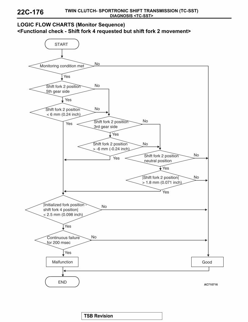
DIAGNOSIS <TC-SST>TWIN CLUTCH- SPORTRONIC SHIFT TRANSMISSION (TC-SST)22C-176
LOGIC FLOW CHARTS (Monitor Sequence) <Functional check - Shift fork 4 requested but shift fork 2 movement>
.
AC710716
START
No
GoodMalfunction
END
No
Yes
Yes
Yes
No
Yes
Yes
No
Yes
No
Yes
NoContinuous failurefor 200 msec
Yes
Yes
No
No
Monitoring condition met
|Initialized fork position -shift fork 4 position| < 2.5 mm (0.098 inch)
Shift fork 2 position5th gear side
Shift fork 2 position < 6 mm (0.24 inch)
Shift fork 2 position3rd gear side
Shift fork 2 position> -6 mm (-0.24 inch)
No
Shift fork 2 positionneutral position
|Shift fork 2 position|> 1.8 mm (0.071 inch)
TSB Revision

DIAGNOSIS <TC-SST>TWIN CLUTCH- SPORTRONIC SHIFT TRANSMISSION (TC-SST) 22C-177
DTC SET CONDITIONS <FUNCTIONAL CHECK - SHIFT FORK 4 REQUESTED BUT SHIFT FORK 2 MOVEMENT>Check Conditions• Voltage of battery: 8 V or more.• Voltage of battery: 16.5 V or less.• Engine speed: 500 r/min or more.• Time since above engine condition: 400 millisec-
ond or more.• Requested shift fork: Shift fork 4.
JUDGMENT CRITERIA• Shift fork position: 6 mm (0.24 inch) [5th gear
side] or less, or −6 mm (−0.24 inch) [3rd gear side] or more, or 1.8 mm (0.071 inch) [neutral position] or more, and Initialized fork position − shift fork 4 position: 2.5 mm (0.098 inch) or less. (200 milli-second)
.
OBD-II DRIVE CYCLE PATTERN <FUNCTIONAL CHECK - SHIFT FORK 4 REQUESTED BUT SHIFT FORK 2 MOVEMENT>The status with the shift fork position 6 mm (0.24 inch) [5th gear side] or more, or with −6 mm (−0.24 inch) [3rd gear side] or less, or with 1.8 mm (0.071 inch) [neutral position] or less and with the initialized fork position − shift fork 4 position 2.5 mm (0.098 inch) or more continues for 200 milliseconds..
TSB Revision

DIAGNOSIS <TC-SST>TWIN CLUTCH- SPORTRONIC SHIFT TRANSMISSION (TC-SST)22C-178
LOGIC FLOW CHARTS (Monitor Sequence) <Functional check - shift fork 4 requested but shift fork 3 movement>
.
No
AC710717
START
No
GoodMalfunction
END
No
Yes
Yes
Yes
No
No
Yes
Monitoring condition met
Yes
No
|Shift fork 3 position|> 1.8 mm (0.071 inch)
Yes
Shift fork 3 positionneutral position
Yes
No
|Initialized fork position -shift fork 4 position| < 2.5 mm (0.098 inch)
Shift fork 3 position6th gear side
Shift fork 3 position> -6 mm (-0.24 inch)
Continuous failurefor 200 msec
TSB Revision

DIAGNOSIS <TC-SST>TWIN CLUTCH- SPORTRONIC SHIFT TRANSMISSION (TC-SST) 22C-179
DTC SET CONDITIONS <FUNCTIONAL CHECK - SHIFT FORK 4 REQUESTED BUT SHIFT FORK 3 MOVEMENT>Check Conditions• Voltage of battery: 8 V or more.• Voltage of battery: 16.5 V or less.• Engine speed: 500 r/min or more.• Time since above engine condition: 400 millisec-
ond or more.• Requested shift fork: Shift fork 4.
JUDGMENT CRITERIA• Shift fork position: −6 mm (−0.24 inch) [6th gear
side] or more, or 1.8 mm (0.071 inch) [neutral position] or more, and initialized fork position − shift fork 4 position: 2.5mm (0.098 inch) or less. (200 millisecond)
.
OBD-II DRIVE CYCLE PATTERN <FUNCTIONAL CHECK - SHIFT FORK 3 REQUESTED BUT SHIFT FORK 4 MOVEMENT>The status of the shift fork position −6 mm (−0.24 inch) [6th gear side] or less, or with 1.8 mm (0.071 inch) [neutral position] or less and with the initialized fork position − shift fork 3 position 2.5 mm (0.098 inch) or more continues for 200 milliseconds..
PROBABLE CAUSES• Malfunction of TC-SST-ECU• Malfunction of TC-SST shift fork
DIAGNOSTIC PROCEDURE
STEP 1. Scan tool CAN bus diagnosticsUsing scan tool MB991958, diagnose the CAN bus lines.Q: Is the check result normal?
YES : Go to Step 2.NO : Repair the CAN bus lines. (Refer to GROUP 54C −
Troubleshooting P.54C-14.) After repairing the CAN bus line, go to Step 2.
STEP 2. Check whether the DTC is reset.Q: Is the DTC No. P184B set?
YES : Replace the TC-SST assembly. (Refer to P.22C-341.)NO : Intermittent malfunction. (Refer to GROUP 00 − How
to Cope with Intermittent Malfunction P.00-15.)
DTC P1852: Shift Fork 1 or 2 opposite direction movement
CAUTION• If there is any problem in the CAN bus lines,
an incorrect diagnostic trouble code may be set. Prior to this diagnosis, diagnose the CAN bus lines.
• Whenever the ECU is replaced, ensure that the CAN bus lines are normal.
.
DIAGNOSTIC FUNCTIONTC-SST-ECU checks that the movement of the shift fork is normal..
DESCRIPTIONS OF MONITOR METHODSThe movements of the shift fork 1 and 2 are deter-mined to be abnormal..
MONITOR EXECUTION• Continuous
.
MONITOR EXECUTION CONDITIONS (OTHER MONITOR AND SENSOR)Other Monitor (There is no temporary DTC stored
in memory for the item monitored below)• P1836: Shift fork 1 malfunction
TSB Revision

DIAGNOSIS <TC-SST>TWIN CLUTCH- SPORTRONIC SHIFT TRANSMISSION (TC-SST)22C-180
• P183D: Shift fork 2 malfunction• P1844: Shift fork 3 malfunction• P184B: Shift fork 4 malfunction
Sensor (The sensor below is determined to be normal)
• Not applicable.
LOGIC FLOW CHARTS (Monitor Sequence) <Functional check - move opposite direction right side>
.
DTC SET CONDITIONS <FUNCTIONAL CHECK - MOVE OPPOSITE DIRECTION RIGHT SIDE>Check Conditions• Voltage of battery: 8 V or more.• Voltage of battery: 16.5 V or less.• Engine speed: 500 r/min or more.• Time since above engine condition: 400 millisec-
ond or more.• Shift fork 1 and 2 current gear: Neutral.• Shift fork 1 and 2 target direction: 0 mm (0 inch)
or less.
JUDGMENT CRITERIA• Shift fork 1 and 2 position: 1.8 mm (0.071 inch) or
more. (250 millisecond).
OBD-II DRIVE CYCLE PATTERN <FUNCTIONAL CHECK - MOVE OPPOSITE DIRECTION RIGHT SIDE>The shift fork 1 and 2 positions remain 1.8 mm (0.071 inch) or less for 250 milliseconds..
AC710720
START
No
GoodMalfunction
END
Continuous failurefor 250 msec
No
Yes
Yes
Monitoring condition met
Yes
NoShift fork position> 1.8 mm (0.071 inch)
TSB Revision

DIAGNOSIS <TC-SST>TWIN CLUTCH- SPORTRONIC SHIFT TRANSMISSION (TC-SST) 22C-181
LOGIC FLOW CHARTS (Monitor Sequence) <Functional check - move opposite direction left side>
.
DTC SET CONDITIONS <FUNCTIONAL CHECK - MOVE OPPOSITE DIRECTION LEFT SIDE>Check Conditions• Voltage of battery: 8 V or more.• Voltage of battery: 16.5 V or less.• Engine speed: 500 r/min or more.• Time since above engine condition: 400 millisec-
ond or more.• Shift fork 1 and 2 current gear: Neutral.• Shift fork 1 and 2 target direction: 0 mm (0 inch)
or more.
JUDGMENT CRITERIA• Shift fork 1 and 2 position: −1.8 mm (−0.071 inch)
or less. (250 millisecond).
OBD-II DRIVE CYCLE PATTERN <FUNCTIONAL CHECK - MOVE OPPOSITE DIRECTION LEFT SIDE>The shift fork 1 and 2 positions remain −1.8 mm (−0.071 inch) or more for 250 milliseconds..
PROBABLE CAUSES• Malfunction of TC-SST-ECU• Malfunction of TC-SST shift fork
AC710721
START
No
GoodMalfunction
END
Continuous failurefor 250 msec
No
Yes
Yes
Monitoring condition met
Yes
NoShift fork position< -1.8 mm (-0.071 inch)
TSB Revision
DIAGNOSIS <TC-SST>TWIN CLUTCH- SPORTRONIC SHIFT TRANSMISSION (TC-SST)22C-182
DIAGNOSTIC PROCEDURE
STEP 1. Scan tool CAN bus diagnosticsUsing scan tool MB991958, diagnose the CAN bus lines.Q: Is the check result normal?
YES : Go to Step 2.NO : Repair the CAN bus lines. (Refer to GROUP 54C −
Troubleshooting P.54C-14.) After repairing the CAN bus line, go to Step 2.
STEP 2. Check whether the DTC is reset.Q: Is the DTC No. P1852 set?
YES : Replace the TC-SST assembly. (Refer to P.22C-341.)NO : Intermittent malfunction. (Refer to GROUP 00 − How
to Cope with Intermittent Malfunction P.00-15.)
DTC P1855: Shift Fork 3 or 4 opposite direction movement
CAUTION• If there is any problem in the CAN bus lines,
an incorrect diagnostic trouble code may be set. Prior to this diagnosis, diagnose the CAN bus lines.
• Whenever the ECU is replaced, ensure that the CAN bus lines are normal.
.
DIAGNOSTIC FUNCTIONTC-SST-ECU checks that the movement of the shift fork is normal..
DESCRIPTIONS OF MONITOR METHODSThe movements of the shift fork 3 and 4 are deter-mined to be abnormal..
MONITOR EXECUTION• Continuous
.
MONITOR EXECUTION CONDITIONS (OTHER MONITOR AND SENSOR)Other Monitor (There is no temporary DTC stored
in memory for the item monitored below)• P1836: Shift fork 1 malfunction• P183D: Shift fork 2 malfunction• P1844: Shift fork 3 malfunction• P184B: Shift fork 4 malfunction
Sensor (The sensor below is determined to be normal)
• Not applicable.
TSB Revision

DIAGNOSIS <TC-SST>TWIN CLUTCH- SPORTRONIC SHIFT TRANSMISSION (TC-SST) 22C-183
LOGIC FLOW CHARTS (Monitor Sequence) <Functional check - move opposite direction right side>
.
DTC SET CONDITIONS <FUNCTIONAL CHECK - MOVE OPPOSITE DIRECTION RIGHT SIDE>Check Conditions• Voltage of battery: 8 V or more.• Voltage of battery: 16.5 V or less.• Engine speed: 500 r/min or more.• Time since above engine condition: 400 millisec-
ond or more.• Shift fork 3 and 4 current gear: Neutral.• Shift fork 3 and 4 target direction: 0 mm (0 inch)
or less.
JUDGMENT CRITERIA• Shift fork 3 and 4 position: 1.8 mm (0.071 inch) or
more. (250 millisecond).
OBD-II DRIVE CYCLE PATTERN <FUNCTIONAL CHECK - MOVE OPPOSITE DIRECTION RIGHT SIDE>The shift fork 3 and 4 positions remain 1.8 mm (0.071 inch) or less for 250 milliseconds..
AC710720
START
No
GoodMalfunction
END
Continuous failurefor 250 msec
No
Yes
Yes
Monitoring condition met
Yes
NoShift fork position> 1.8 mm (0.071 inch)
TSB Revision

DIAGNOSIS <TC-SST>TWIN CLUTCH- SPORTRONIC SHIFT TRANSMISSION (TC-SST)22C-184
LOGIC FLOW CHARTS (Monitor Sequence) <Functional check - move opposite direction left side>
.
DTC SET CONDITIONS <FUNCTIONAL CHECK - MOVE OPPOSITE DIRECTION LEFT SIDE>Check Conditions• Voltage of battery: 8 V or more.• Voltage of battery: 16.5 V or less.• Engine speed: 500 r/min or more.• Time since above engine condition: 400 millisec-
ond or more.• Shift fork 3 and 4 current gear: Neutral.• Shift fork 3 and 4 target direction: 0 mm (0 inch)
or more.
JUDGMENT CRITERIA• Shift fork 3 and 4 position: −1.8 mm (−0.071 inch)
or less. (250 millisecond)
.
OBD-II DRIVE CYCLE PATTERN <FUNCTIONAL CHECK - MOVE OPPOSITE DIRECTION LEFT SIDE>The shift fork 3 and 4 positions remain −1.8 mm (−0.071 inch) or more for 250 milliseconds..
PROBABLE CAUSES• Malfunction of TC-SST-ECU• Malfunction of TC-SST shift fork
AC710721
START
No
GoodMalfunction
END
Continuous failurefor 250 msec
No
Yes
Yes
Monitoring condition met
Yes
NoShift fork position< -1.8 mm (-0.071 inch)
TSB Revision

DIAGNOSIS <TC-SST>TWIN CLUTCH- SPORTRONIC SHIFT TRANSMISSION (TC-SST) 22C-185
DIAGNOSTIC PROCEDURE
STEP 1. Scan tool CAN bus diagnosticsUsing scan tool MB991958, diagnose the CAN bus lines.Q: Is the check result normal?
YES : Go to Step 2.NO : Repair the CAN bus lines. (Refer to GROUP 54C −
Troubleshooting P.54C-14.) After repairing the CAN bus line, go to Step 2.
STEP 2. Check whether the DTC is reset.Q: Is the DTC No. P1855 set?
YES : Replace the TC-SST assembly. (Refer to P.22C-341.)NO : Intermittent malfunction. (Refer to GROUP 00 − How
to Cope with Intermittent Malfunction P.00-15.)
DTC P1857: Odd number gear axle interlock
CAUTION• If there is any problem in the CAN bus lines,
an incorrect diagnostic trouble code may be set. Prior to this diagnosis, diagnose the CAN bus lines.
• Whenever the ECU is replaced, ensure that the CAN bus lines are normal.
.
DIAGNOSTIC FUNCTIONTC-SST-ECU checks that the gear engagement is normal..
DESCRIPTIONS OF MONITOR METHODSThe two gears are determined to be engaged in the odd number gear range..
MONITOR EXECUTION• Continuous
.
MONITOR EXECUTION CONDITIONS (OTHER MONITOR AND SENSOR)Other Monitor (There is no temporary DTC stored
in memory for the item monitored below)• Not applicable
Sensor (The sensor below is determined to be normal)
• Not applicable.
TSB Revision

DIAGNOSIS <TC-SST>TWIN CLUTCH- SPORTRONIC SHIFT TRANSMISSION (TC-SST)22C-186
LOGIC FLOW CHARTS (Monitor Sequence)
.
DTC SET CONDITIONSCheck Conditions• Voltage of battery: 8 V or more.• Voltage of battery: 16.5 V or less.• Engine speed: 500 r/min or more.• Time since above engine condition: 400 millisec-
ond or more.
JUDGMENT CRITERIA• Shift fork 1 and 2 position: 3.8 mm (0.15 inch) or
more. (500 millisecond)
.
OBD-II DRIVE CYCLE PATTERNThe shift fork 1 and 2 positions remain 3.8 mm (0.15 inch) or less for 500 milliseconds..
PROBABLE CAUSES• Malfunction of TC-SST-ECU• Malfunction of TC-SST gear
DIAGNOSTIC PROCEDURE
STEP 1. Scan tool CAN bus diagnosticsUsing scan tool MB991958, diagnose the CAN bus lines.Q: Is the check result normal?
YES : Go to Step 2.NO : Repair the CAN bus lines. (Refer to GROUP 54C −
Troubleshooting P.54C-14.) After repairing the CAN bus line, go to Step 2.
AC710722
START
No
GoodMalfunction
END
No
Yes
Yes
Yes
No
Monitoring condition met
|Shift fork 1 position|> 3.8 mm
Yes
No|Shift fork 2 position|> 3.8 mm
Continuous failurefor 500 msec
TSB Revision

DIAGNOSIS <TC-SST>TWIN CLUTCH- SPORTRONIC SHIFT TRANSMISSION (TC-SST) 22C-187
STEP 2. Check whether the DTC is reset.Q: Is DTC No. P1857 set?
YES : Replace the TC-SST assembly. (Refer to P.22C-341.)NO : Intermittent malfunction. (Refer to GROUP 00 − How
to Cope with Intermittent Malfunction P.00-15.)
DTC P1858: Even number gear axle interlock
CAUTION• If there is any problem in the CAN bus lines,
an incorrect diagnostic trouble code may be set. Prior to this diagnosis, diagnose the CAN bus lines.
• Whenever the ECU is replaced, ensure that the CAN bus lines are normal.
.
DIAGNOSTIC FUNCTIONTC-SST-ECU checks that the gear engagement is normal..
DESCRIPTIONS OF MONITOR METHODSThe two gears are determined to be engaged in the even number gear range.
.
MONITOR EXECUTION• Continuous
.
MONITOR EXECUTION CONDITIONS (OTHER MONITOR AND SENSOR)Other Monitor (There is no temporary DTC stored
in memory for the item monitored below)• Not applicable
Sensor (The sensor below is determined to be normal)
• Not applicable.
TSB Revision

DIAGNOSIS <TC-SST>TWIN CLUTCH- SPORTRONIC SHIFT TRANSMISSION (TC-SST)22C-188
LOGIC FLOW CHARTS (Monitor Sequence)
.
DTC SET CONDITIONSCheck Conditions• Voltage of battery: 8 V or more.• Voltage of battery: 16.5 V or less.• Engine speed: 500 r/min or more.• Time since above engine condition: 400 millisec-
ond or more.
JUDGMENT CRITERIA• Shift fork 3 and 4 position: 3.8 mm (0.15 inch) or
more. (500 millisecond)
.
OBD-II DRIVE CYCLE PATTERNThe shift fork 3 and 4 positions remain 3.8 mm (0.15 inch) or less for 500 milliseconds..
PROBABLE CAUSES• Malfunction of TC-SST-ECU• Malfunction of TC-SST gear
DIAGNOSTIC PROCEDURE
STEP 1. Scan tool CAN bus diagnosticsUsing scan tool MB991958, diagnose the CAN bus lines.Q: Is the check result normal?
YES : Go to Step 2.NO : Repair the CAN bus lines. (Refer to GROUP 54C −
Troubleshooting P.54C-14.) After repairing the CAN bus line, go to Step 2.
AC710723
START
No
GoodMalfunction
END
No
Yes
Yes
Yes
No
Monitoring condition met
|Shift fork 3 position|> 3.8 mm (0.15 inch)
Yes
No|Shift fork 4 position|> 3.8 mm (0.15 inch)
Continuous failurefor 500 msec
TSB Revision

DIAGNOSIS <TC-SST>TWIN CLUTCH- SPORTRONIC SHIFT TRANSMISSION (TC-SST) 22C-189
STEP 2. Check whether the DTC is reset.Q: Is DTC No. P1858 set?
YES : Replace the TC-SST assembly. (Refer to P.22C-341.)NO : Intermittent malfunction. (Refer to GROUP 00 − How
to Cope with Intermittent Malfunction P.00-15.)
DTC P1859: Disengagement too late with clutch 1
CAUTION• If there is any problem in the CAN bus lines,
an incorrect diagnostic trouble code may be set. Prior to this diagnosis, diagnose the CAN bus lines.
• Whenever the ECU is replaced, ensure that the CAN bus lines are normal.
.
DIAGNOSTIC FUNCTIONTC-SST-ECU checks that the clutch 1 is normal..
DESCRIPTIONS OF MONITOR METHODSThe disengagement of the clutch 1 is determined to be late..
MONITOR EXECUTION• Continuous
.
MONITOR EXECUTION CONDITIONS (OTHER MONITOR AND SENSOR)Other Monitor (There is no temporary DTC stored
in memory for the item monitored below)• P0841: Clutch 1 pressure sensor system (Poor
performance)• P0842: Clutch 1 pressure sensor system (Output
low range out)• P0843: Clutch 1 pressure sensor system (Output
high range out)• P1836: Shift fork 1 malfunction• P183D: Shift fork 2 malfunction
Sensor (The sensor below is determined to be normal)
• Clutch 1 pressure sensor.
LOGIC FLOW CHARTS (Monitor Sequence)
.
AC710675
START
No
GoodMalfunction
END
Yes
Malfunction criteria met
Yes
Monitoring condition met
No
TSB Revision

DIAGNOSIS <TC-SST>TWIN CLUTCH- SPORTRONIC SHIFT TRANSMISSION (TC-SST)22C-190
DTC SET CONDITIONSCheck Conditions• Voltage of battery: 8 V or more.• Voltage of battery: 16.5 V or less.• Engine speed: 500 r/min or more.• Time since above engine condition: 400 millisec-
ond or more.• Clutch 1 (odd) state: Disengaging.
JUDGMENT CRITERIA•
• The disengagement time of the clutch (depends on the fluid temperature) is outside the threshold value.
.
OBD-II DRIVE CYCLE PATTERNThe disengagement time of the clutch (depends on the fluid temperature) corresponds with the threshold value. .
PROBABLE CAUSES• Malfunction of TC-SST-ECU
DIAGNOSTIC PROCEDURE
STEP 1. Scan tool CAN bus diagnosticsUsing scan tool MB991958, diagnose the CAN bus lines.Q: Is the check result normal?
YES : Go to Step 2.NO : Repair the CAN bus lines. (Refer to GROUP 54C −
Troubleshooting P.54C-14.) After repairing the CAN bus line, go to Step 2.
STEP 2. Check whether the DTC is reset.Q: Is DTC No. P1859 set?
YES : Replace the TC-SST assembly. (Refer to P.22C-341.)NO : Intermittent malfunction. (Refer to GROUP 00 − How
to Cope with Intermittent Malfunction P.00-15.)
DTC P185A: Engagement too late with clutch 1
CAUTION• If there is any problem in the CAN bus lines,
an incorrect diagnostic trouble code may be set. Prior to this diagnosis, diagnose the CAN bus lines.
• Whenever the ECU is replaced, ensure that the CAN bus lines are normal.
.
DIAGNOSTIC FUNCTIONTC-SST-ECU checks that the clutch 1 is normal..
DESCRIPTIONS OF MONITOR METHODSThe engagement of the clutch 1 is determined to be late..
PROBABLE CAUSES• Malfunction of TC-SST-ECU
AC710825
Max
imum
allo
wed
tim
e (s
ec)
25
20
15
10
5
-30-20-10 0 60 120
Fluid temperature (degC)AB
TSB Revision

DIAGNOSIS <TC-SST>TWIN CLUTCH- SPORTRONIC SHIFT TRANSMISSION (TC-SST) 22C-191
DIAGNOSTIC PROCEDURE
STEP 1. Scan tool CAN bus diagnosticsUsing scan tool MB991958, diagnose the CAN bus lines.Q: Is the check result normal?
YES : Go to Step 2.NO : Repair the CAN bus lines. (Refer to GROUP 54C −
Troubleshooting P.54C-14.) After repairing the CAN bus line, go to Step 2.
STEP 2. Check whether the DTC is reset.Q: Is DTC No. P185A set?
YES : Replace the TC-SST assembly. (Refer to P.22C-341.)NO : Intermittent malfunction. (Refer to GROUP 00 − How
to Cope with Intermittent Malfunction P.00-15.)
DTC P185B: Disengagement too late with clutch 2
CAUTION• If there is any problem in the CAN bus lines,
an incorrect diagnostic trouble code may be set. Prior to this diagnosis, diagnose the CAN bus lines.
• Whenever the ECU is replaced, ensure that the CAN bus lines are normal.
.
DIAGNOSTIC FUNCTIONTC-SST-ECU checks that the clutch 2 is normal..
DESCRIPTIONS OF MONITOR METHODSThe disengagement of the clutch 2 is determined to be late..
MONITOR EXECUTION• Continuous
.
MONITOR EXECUTION CONDITIONS (OTHER MONITOR AND SENSOR)Other Monitor (There is no temporary DTC stored
in memory for the item monitored below)• P0846: Clutch 2 pressure sensor system (Poor
performance)• P0847: Clutch 2 pressure sensor system (Output
low range out)• P0848: Clutch 2 pressure sensor system (Output
high range out)• P1844: Shift fork 3 malfunction• P184B: Shift fork 4 malfunction
Sensor (The sensor below is determined to be normal)
• Clutch 2 pressure sensor.
TSB Revision

DIAGNOSIS <TC-SST>TWIN CLUTCH- SPORTRONIC SHIFT TRANSMISSION (TC-SST)22C-192
LOGIC FLOW CHARTS (Monitor Sequence)
.
DTC SET CONDITIONSCheck Conditions• Voltage of battery: 8 V or more.• Voltage of battery: 16.5 V or less.• Engine speed: 500 r/min or more.• Time since above engine condition: 400 millisec-
ond or more.• Clutch 2 (even) state: Disengaging.
JUDGMENT CRITERIA•
• The disengagement time of the clutch (depends on the fluid temperature) is outside the threshold value.
.
OBD-II DRIVE CYCLE PATTERNThe disengagement time of the clutch (depends on the fluid temperature) corresponds with the threshold value. .
PROBABLE CAUSES• Malfunction of TC-SST-ECU
DIAGNOSTIC PROCEDURE
STEP 1. Scan tool CAN bus diagnosticsUsing scan tool MB991958, diagnose the CAN bus lines.Q: Is the check result normal?
YES : Go to Step 2.NO : Repair the CAN bus lines. (Refer to GROUP 54C −
Troubleshooting P.54C-14.) After repairing the CAN bus line, go to Step 2.
AC710675
START
No
GoodMalfunction
END
Yes
Malfunction criteria met
Yes
Monitoring condition met
No
AC710825
Max
imum
allo
wed
tim
e (s
ec)
25
20
15
10
5
-30-20-10 0 60 120
Fluid temperature (degC)AB
TSB Revision

DIAGNOSIS <TC-SST>TWIN CLUTCH- SPORTRONIC SHIFT TRANSMISSION (TC-SST) 22C-193
STEP 2. Check whether the DTC is reset.Q: Is DTC No. P185B set?
YES : Replace the TC-SST assembly. (Refer to P.22C-341.)NO : Intermittent malfunction. (Refer to GROUP 00 − How
to Cope with Intermittent Malfunction P.00-15.)
DTC P185C: Engagement too late with clutch 2
CAUTION• If there is any problem in the CAN bus lines,
an incorrect diagnostic trouble code may be set. Prior to this diagnosis, diagnose the CAN bus lines.
• Whenever the ECU is replaced, ensure that the CAN bus lines are normal.
.
DIAGNOSTIC FUNCTIONTC-SST-ECU checks that the clutch 2 is normal..
DESCRIPTIONS OF MONITOR METHODSThe engagement of the clutch 2 is determined to be late..
PROBABLE CAUSES• Malfunction of TC-SST-ECU
DIAGNOSTIC PROCEDURE
STEP 1. Scan tool CAN bus diagnosticsUsing scan tool MB991958, diagnose the CAN bus lines.Q: Is the check result normal?
YES : Go to Step 2.NO : Repair the CAN bus lines. (Refer to GROUP 54C −
Troubleshooting P.54C-14.) After repairing the CAN bus line, go to Step 2.
STEP 2. Check whether the DTC is reset.Q: Is DTC No. P185C set?
YES : Replace the TC-SST assembly. (Refer to P.22C-341.)NO : Intermittent malfunction. (Refer to GROUP 00 − How
to Cope with Intermittent Malfunction P.00-15.)
DTC P185D: Clutch open not possible
CAUTION• If there is any problem in the CAN bus lines,
an incorrect diagnostic trouble code may be set. Prior to this diagnosis, diagnose the CAN bus lines.
• Whenever the ECU is replaced, ensure that the CAN bus lines are normal.
.
DIAGNOSTIC FUNCTIONTC-SST-ECU checks that the clutch 1 and 2 are nor-mal.
.
DESCRIPTIONS OF MONITOR METHODSThe disengagement of the clutch 1 and 2 are deter-mined to be impossible..
MONITOR EXECUTION• Continuous
.
TSB Revision

DIAGNOSIS <TC-SST>TWIN CLUTCH- SPORTRONIC SHIFT TRANSMISSION (TC-SST)22C-194
MONITOR EXECUTION CONDITIONS (OTHER MONITOR AND SENSOR)Other Monitor (There is no temporary DTC stored
in memory for the item monitored below)• Not applicable
Sensor (The sensor below is determined to be normal)
• Not applicable.
LOGIC FLOW CHARTS (Monitor Sequence)
.
DTC SET CONDITIONSCheck Conditions• Voltage of battery: 8 V or more.• Voltage of battery: 16.5 V or less.• Engine speed: 500 r/min or more.• Time since above engine condition: 400 millisec-
ond or more.• Clutch 1 state: Not stroking (not to close).• Clutch 2 state: Not stroking (not to close).• Input shaft 1 (odd) gear: Engaged.• Input shaft 2 (even) gear: Engaged.• Current gear: Not 1st gear and reverse gear.
JUDGMENT CRITERIA• Current clutch torque − Clutch 1 (odd) permit
torque − Clutch 2 (even) permit torque: (100 N⋅ m (74 ft-lb) + (Current clutch torque × 0.25%)) or more. (2 seconds)
.
OBD-II DRIVE CYCLE PATTERNThe current clutch torque − clutch 1 (odd) permit torque − clutch 2 (even) permit torque remain (100 N⋅ m (74 ft-lb) + (current clutch torque × 0.25%)) or less for 2 seconds..
PROBABLE CAUSES• Clutch malfunction
AC710724
START
No
GoodMalfunction
END
No
Yes
Yes
No
Monitoring condition met
Calculated torque> calculated criteria
Yes
Continuous failurefor 2 sec
TSB Revision

DIAGNOSIS <TC-SST>TWIN CLUTCH- SPORTRONIC SHIFT TRANSMISSION (TC-SST) 22C-195
DIAGNOSTIC PROCEDURE
STEP 1. Scan tool CAN bus diagnosticsUsing scan tool MB991958, diagnose the CAN bus lines.Q: Is the check result normal?
YES : Go to Step 2.NO : Repair the CAN bus lines. (Refer to GROUP 54C −
Troubleshooting P.54C-14.) After repairing the CAN bus line, go to Step 2.
STEP 2. Check whether the DTC is reset.Q: Is DTC No. P185D set?
YES : Replace the TC-SST assembly. (Refer to P.22C-341.)NO : Intermittent malfunction. (Refer to GROUP 00 − How
to Cope with Intermittent Malfunction P.00-15.)
DTC P1862: High side 1 system (Overcurrent)
CAUTION• If there is any problem in the CAN bus lines,
an incorrect diagnostic trouble code may be set. Prior to this diagnosis, diagnose the CAN bus lines.
• Whenever the ECU is replaced, ensure that the CAN bus lines are normal.
.
DIAGNOSTIC FUNCTIONTC-SST-ECU checks that the high side 1 circuit is normal..
DESCRIPTIONS OF MONITOR METHODSThe supply current to the high side 1 is determined to be overcurrent..
MONITOR EXECUTION• Continuous
.
MONITOR EXECUTION CONDITIONS (OTHER MONITOR AND SENSOR)Other Monitor (There is no temporary DTC stored
in memory for the item monitored below)• P0758: Shift select solenoid 2 system (Open cir-
cuit)
• P0976: Shift select solenoid 2 system (Short to ground)
• P0977: Shift select solenoid 2 system (Short to power supply)
• P0746: Line pressure solenoid system (Drive cur-rent range out)
• P0960: Line pressure solenoid system (Open cir-cuit)
• P0961: Line pressure solenoid system (Overvolt-age)
• P0962: Line pressure solenoid system (Short to ground)
• P0963: Line pressure solenoid system (Short to power supply)
• P0968: Shift/cooling switching solenoid system (Open circuit)
• P0970: Shift/cooling switching solenoid system (Short to ground)
• P0971: Shift/cooling switching solenoid system (Short to power supply)
Sensor (The sensor below is determined to be normal)
• Shift select solenoid 2• Line pressure solenoid• Shift/cooling switching solenoid
.
TSB Revision

DIAGNOSIS <TC-SST>TWIN CLUTCH- SPORTRONIC SHIFT TRANSMISSION (TC-SST)22C-196
LOGIC FLOW CHARTS (Monitor Sequence)
.
DTC SET CONDITIONSCheck Conditions• Voltage of battery: 8 V or more.• Voltage of battery: 16.5 V or less.• High side 1 switch: ON.
JUDGMENT CRITERIA• FET (Field Effect Transistor) current: 8.1 A or
more, and FET (Field Effect Transistor) output: 100 mV or less (1 second).
.
OBD-II DRIVE CYCLE PATTERNThe status with the current of the FET channel shunt 8.1 A or less and with the FET channel output 100 mV or more continues for 1 second..
PROBABLE CAUSES• Malfunction of TC-SST-ECU
DIAGNOSTIC PROCEDURE
STEP 1. Scan tool CAN bus diagnosticsUsing scan tool MB991958, diagnose the CAN bus lines.Q: Is the check result normal?
YES : Go to Step 2.NO : Repair the CAN bus lines. (Refer to GROUP 54C −
Troubleshooting P.54C-14.) After repairing the CAN bus line, go to Step 2.
AC710725
START
No
GoodMalfunction
END
No
Yes
Yes
Yes
No
Monitoring condition met
FET* current > 8.1 A
Yes
NoFET* output < 100 mV
Continuous failurefor 1 sec
*FET : Field Effect Transistor
TSB Revision

DIAGNOSIS <TC-SST>TWIN CLUTCH- SPORTRONIC SHIFT TRANSMISSION (TC-SST) 22C-197
STEP 2. Check whether the DTC is reset.Q: Is DTC No. P1862 set?
YES : Replace the TC-SST assembly. (Refer to P.22C-341.)NO : Intermittent malfunction. (Refer to GROUP 00 − How
to Cope with Intermittent Malfunction P.00-15.)
DTC P1863: High side 1 system (Open circuit)
CAUTION• If there is any problem in the CAN bus lines,
an incorrect diagnostic trouble code may be set. Prior to this diagnosis, diagnose the CAN bus lines.
• Whenever the ECU is replaced, ensure that the CAN bus lines are normal.
.
DIAGNOSTIC FUNCTIONTC-SST-ECU checks that the high side 1 circuit is normal..
DESCRIPTIONS OF MONITOR METHODSThe high side 1 circuit is determined to be open..
MONITOR EXECUTION• Continuous
.
MONITOR EXECUTION CONDITIONS (OTHER MONITOR AND SENSOR)Other Monitor (There is no temporary DTC stored
in memory for the item monitored below)• P0758: Shift select solenoid 2 system (Open cir-
cuit)
• P0976: Shift select solenoid 2 system (Short to ground)
• P0977: Shift select solenoid 2 system (Short to power supply)
• P0746: Line pressure solenoid system (Drive cur-rent range out)
• P0960: Line pressure solenoid system (Open cir-cuit)
• P0961: Line pressure solenoid system (Overvolt-age)
• P0962: Line pressure solenoid system (Short to ground)
• P0963: Line pressure solenoid system (Short to power supply)
• P0968: Shift/cooling switching solenoid system (Open circuit)
• P0970: Shift/cooling switching solenoid system (Short to ground)
• P0971: Shift/cooling switching solenoid system (Short to power supply)
Sensor (The sensor below is determined to be normal)
• Shift select solenoid 2• Line pressure solenoid• Shift/cooling switching solenoid
.
TSB Revision
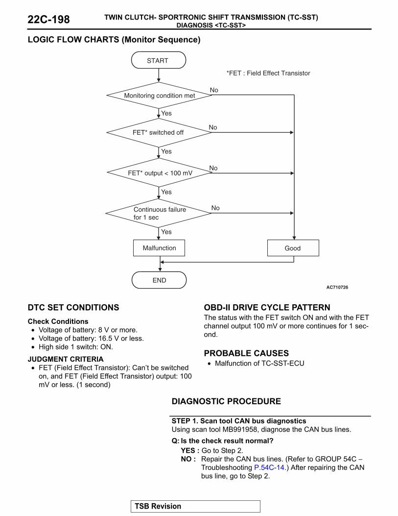
DIAGNOSIS <TC-SST>TWIN CLUTCH- SPORTRONIC SHIFT TRANSMISSION (TC-SST)22C-198
LOGIC FLOW CHARTS (Monitor Sequence)
.
DTC SET CONDITIONSCheck Conditions• Voltage of battery: 8 V or more.• Voltage of battery: 16.5 V or less.• High side 1 switch: ON.
JUDGMENT CRITERIA• FET (Field Effect Transistor): Cant be switched
on, and FET (Field Effect Transistor) output: 100 mV or less. (1 second)
.
OBD-II DRIVE CYCLE PATTERNThe status with the FET switch ON and with the FET channel output 100 mV or more continues for 1 sec-ond..
PROBABLE CAUSES• Malfunction of TC-SST-ECU
DIAGNOSTIC PROCEDURE
STEP 1. Scan tool CAN bus diagnosticsUsing scan tool MB991958, diagnose the CAN bus lines.Q: Is the check result normal?
YES : Go to Step 2.NO : Repair the CAN bus lines. (Refer to GROUP 54C −
Troubleshooting P.54C-14.) After repairing the CAN bus line, go to Step 2.
AC710726
START
No
GoodMalfunction
END
No
Yes
Yes
Yes
No
Monitoring condition met
FET* switched off
Yes
NoFET* output < 100 mV
Continuous failurefor 1 sec
*FET : Field Effect Transistor
TSB Revision

DIAGNOSIS <TC-SST>TWIN CLUTCH- SPORTRONIC SHIFT TRANSMISSION (TC-SST) 22C-199
STEP 2. Check whether the DTC is reset.Q: Is DTC No. P1863 set?
YES : Replace the TC-SST assembly. (Refer to P.22C-341.)NO : Intermittent malfunction. (Refer to GROUP 00 − How
to Cope with Intermittent Malfunction P.00-15.)
DTC P1864: High side 1 system (Short to power supply)
CAUTION• If there is any problem in the CAN bus lines,
an incorrect diagnostic trouble code may be set. Prior to this diagnosis, diagnose the CAN bus lines.
• Whenever the ECU is replaced, ensure that the CAN bus lines are normal.
.
DIAGNOSTIC FUNCTIONTC-SST-ECU checks that the high side 1 circuit is normal..
DESCRIPTIONS OF MONITOR METHODSThe high side 1 circuit is determined to be short to power supply..
MONITOR EXECUTION• Continuous
.
MONITOR EXECUTION CONDITIONS (OTHER MONITOR AND SENSOR)Other Monitor (There is no temporary DTC stored
in memory for the item monitored below)• P0758: Shift select solenoid 2 system (Open cir-
cuit)
• P0976: Shift select solenoid 2 system (Short to ground)
• P0977: Shift select solenoid 2 system (Short to power supply)
• P0746: Line pressure solenoid system (Drive cur-rent range out)
• P0960: Line pressure solenoid system (Open cir-cuit)
• P0961: Line pressure solenoid system (Overvolt-age)
• P0962: Line pressure solenoid system (Short to ground)
• P0963: Line pressure solenoid system (Short to power supply)
• P0968: Shift/cooling switching solenoid system (Open circuit)
• P0970: Shift/cooling switching solenoid system (Short to ground)
• P0971: Shift/cooling switching solenoid system (Short to power supply)
Sensor (The sensor below is determined to be normal)
• Shift select solenoid 2• Line pressure solenoid• Shift/cooling switching solenoid
.
TSB Revision

DIAGNOSIS <TC-SST>TWIN CLUTCH- SPORTRONIC SHIFT TRANSMISSION (TC-SST)22C-200
LOGIC FLOW CHARTS (Monitor Sequence)
.
DTC SET CONDITIONSCheck Conditions• Voltage of battery: 8 V or more.• Voltage of battery: 16.5 V or less.• High side 1 switch: OFF.
JUDGMENT CRITERIA• FET (Field Effect Transistor): Cant be switched
off. (12 seconds)
.
OBD-II DRIVE CYCLE PATTERNThe FET switch remains OFF for 12 seconds..
PROBABLE CAUSES• Malfunction of TC-SST-ECU
DIAGNOSTIC PROCEDURE
STEP 1. Scan tool CAN bus diagnosticsUsing scan tool MB991958, diagnose the CAN bus lines.Q: Is the check result normal?
YES : Go to Step 2.NO : Repair the CAN bus lines. (Refer to GROUP 54C −
Troubleshooting P.54C-14.) After repairing the CAN bus line, go to Step 2.
AC710727
START
No
GoodMalfunction
END
Continuous failurefor 12 sec
No
Yes
Yes
Monitoring condition met
Yes
NoFET* can't switched off
*FET : Field Effect Transistor
TSB Revision

DIAGNOSIS <TC-SST>TWIN CLUTCH- SPORTRONIC SHIFT TRANSMISSION (TC-SST) 22C-201
STEP 2. Check whether the DTC is reset.Q: Is DTC No. P1864 set?
YES : Replace the TC-SST assembly. (Refer to P.22C-341.)NO : Intermittent malfunction. (Refer to GROUP 00 − How
to Cope with Intermittent Malfunction P.00-15.)
DTC P1866: High side 2 system (Overcurrent)
CAUTION• If there is any problem in the CAN bus lines,
an incorrect diagnostic trouble code may be set. Prior to this diagnosis, diagnose the CAN bus lines.
• Whenever the ECU is replaced, ensure that the CAN bus lines are normal.
.
DIAGNOSTIC FUNCTIONTC-SST-ECU checks that the high side 2 circuit is normal..
DESCRIPTIONS OF MONITOR METHODSThe supply current to the high side 2 is determined to be overcurrent..
MONITOR EXECUTION• Continuous
.
MONITOR EXECUTION CONDITIONS (OTHER MONITOR AND SENSOR)Other Monitor (There is no temporary DTC stored
in memory for the item monitored below)• P0776: Clutch cooling flow solenoid system
(Drive current range out)• P0777: Clutch cooling flow solenoid system
(Stuck)• P0964: Clutch cooling flow solenoid system
(Open circuit)
• P0965: Clutch cooling flow solenoid system (Overvoltage)
• P0966: Clutch cooling flow solenoid system (Short to ground)
• P0967: Clutch cooling flow solenoid system (Short to power supply)
• P2718: Clutch/shift pressure solenoid 1 system (Open circuit)
• P2719: Clutch/shift pressure solenoid 1 system (Overcurrent)
• P2720: Clutch/shift pressure solenoid 1 system (Short to ground)
• P2721: Clutch/shift pressure solenoid 1 system (Short to power supply)
• P2733: Clutch/shift switching solenoid 1, spool stuck
• P2736: Clutch/shift switching solenoid 1 system (Open circuit)
• P2738: Clutch/shift switching solenoid 1 system (Short to ground)
• P2739: Clutch/shift switching solenoid 1 system (Short to power supply)
• P181B: Clutch 1 (Pressure low range out)• P181C: Clutch 1 (Pressure high range out)• P1859: Disengagement too late with clutch 1
Sensor (The sensor below is determined to be normal)
• Clutch cooling flow solenoid• Clutch/shift pressure solenoid 1• Clutch/shift switching solenoid 1
.
TSB Revision

DIAGNOSIS <TC-SST>TWIN CLUTCH- SPORTRONIC SHIFT TRANSMISSION (TC-SST)22C-202
LOGIC FLOW CHARTS (Monitor Sequence)
.
DTC SET CONDITIONSCheck Conditions• Voltage of battery: 8 V or more.• Voltage of battery: 16.5 V or less.• High side 2 switch: ON.
JUDGMENT CRITERIA• FET (Field Effect Transistor) current: 8.1 A or
more, and FET (Field Effect Transistor) output: 100 mV or less. (1 second)
.
OBD-II DRIVE CYCLE PATTERNThe status with the current of the FET channel shunt 8.1 A or less and with the FET channel output 100 mV or more continues for 1 second..
PROBABLE CAUSES• Malfunction of TC-SST-ECU
DIAGNOSTIC PROCEDURE
STEP 1. Scan tool CAN bus diagnosticsUsing scan tool MB991958, diagnose the CAN bus lines.Q: Is the check result normal?
YES : Go to Step 2.NO : Repair the CAN bus lines. (Refer to GROUP 54C −
Troubleshooting P.54C-14.) After repairing the CAN bus line, go to Step 2.
AC710725
START
No
GoodMalfunction
END
No
Yes
Yes
Yes
No
Monitoring condition met
FET* current > 8.1 A
Yes
NoFET* output < 100 mV
Continuous failurefor 1 sec
*FET : Field Effect Transistor
TSB Revision

DIAGNOSIS <TC-SST>TWIN CLUTCH- SPORTRONIC SHIFT TRANSMISSION (TC-SST) 22C-203
STEP 2. Check whether the DTC is reset.Q: Is DTC No. P1866 set?
YES : Replace the TC-SST assembly. (Refer to P.22C-341.)NO : Intermittent malfunction. (Refer to GROUP 00 − How
to Cope with Intermittent Malfunction P.00-15.)
DTC P1867: High side 2 system (Open circuit)
CAUTION• If there is any problem in the CAN bus lines,
an incorrect diagnostic trouble code may be set. Prior to this diagnosis, diagnose the CAN bus lines.
• Whenever the ECU is replaced, ensure that the CAN bus lines are normal.
.
DIAGNOSTIC FUNCTIONTC-SST-ECU checks that the high side 2 circuit is normal..
DESCRIPTIONS OF MONITOR METHODSThe high side 2 circuit is determined to be open..
MONITOR EXECUTION• Continuous
.
MONITOR EXECUTION CONDITIONS (OTHER MONITOR AND SENSOR)Other Monitor (There is no temporary DTC stored
in memory for the item monitored below)• P0776: Clutch cooling flow solenoid system
(Drive current range out)• P0777: Clutch cooling flow solenoid system
(Stuck)• P0964: Clutch cooling flow solenoid system
(Open circuit)
• P0965: Clutch cooling flow solenoid system (Overvoltage)
• P0966: Clutch cooling flow solenoid system (Short to ground)
• P0967: Clutch cooling flow solenoid system (Short to power supply)
• P2718: Clutch/shift pressure solenoid 1 system (Open circuit)
• P2719: Clutch/shift pressure solenoid 1 system (Overcurrent)
• P2720: Clutch/shift pressure solenoid 1 system (Short to ground)
• P2721: Clutch/shift pressure solenoid 1 system (Short to power supply)
• P2733: Clutch/shift switching solenoid 1, spool stuck
• P2736: Clutch/shift switching solenoid 1 system (Open circuit)
• P2738: Clutch/shift switching solenoid 1 system (Short to ground)
• P2739: Clutch/shift switching solenoid 1 system (Short to power supply)
• P181B: Clutch 1 (Pressure low range out)• P181C: Clutch 1 (Pressure high range out)• P1859: Disengagement too late with clutch 1
Sensor (The sensor below is determined to be normal)
• Clutch cooling flow solenoid• Clutch/shift pressure solenoid 1• Clutch/shift switching solenoid 1
.
TSB Revision

DIAGNOSIS <TC-SST>TWIN CLUTCH- SPORTRONIC SHIFT TRANSMISSION (TC-SST)22C-204
LOGIC FLOW CHARTS (Monitor Sequence)
.
DTC SET CONDITIONSCheck Conditions• Voltage of battery: 8 V or more.• Voltage of battery: 16.5 V or less.• High side 2 switch: ON.
JUDGMENT CRITERIA• FET (Field Effect Transistor): Cant be switched
on, and FET (Field Effect Transistor) output: 100 mV or less. (1 second)
.
OBD-II DRIVE CYCLE PATTERNThe status with the FET switch ON and with the FET channel output 100 mV or more continues for 1 sec-ond..
PROBABLE CAUSES• Malfunction of TC-SST-ECU
DIAGNOSTIC PROCEDURE
STEP 1. Scan tool CAN bus diagnosticsUsing scan tool MB991958, diagnose the CAN bus lines.Q: Is the check result normal?
YES : Go to Step 2.NO : Repair the CAN bus lines. (Refer to GROUP 54C −
Troubleshooting P.54C-14.) After repairing the CAN bus line, go to Step 2.
AC710726
START
No
GoodMalfunction
END
No
Yes
Yes
Yes
No
Monitoring condition met
FET* switched off
Yes
NoFET* output < 100 mV
Continuous failurefor 1 sec
*FET : Field Effect Transistor
TSB Revision

DIAGNOSIS <TC-SST>TWIN CLUTCH- SPORTRONIC SHIFT TRANSMISSION (TC-SST) 22C-205
STEP 2. Check whether the DTC is reset.Q: Is DTC No. P1867 set?
YES : Replace the TC-SST assembly. (Refer to P.22C-341.)NO : Intermittent malfunction. (Refer to GROUP 00 − How
to Cope with Intermittent Malfunction P.00-15.)
DTC P1868: High side 2 system (Short to power supply)
CAUTION• If there is any problem in the CAN bus lines,
an incorrect diagnostic trouble code may be set. Prior to this diagnosis, diagnose the CAN bus lines.
• Whenever the ECU is replaced, ensure that the CAN bus lines are normal.
.
DIAGNOSTIC FUNCTIONTC-SST-ECU checks that the high side 2 circuit is normal..
DESCRIPTIONS OF MONITOR METHODSThe high side 2 circuit is determined to be short to power supply..
MONITOR EXECUTION• Continuous
.
MONITOR EXECUTION CONDITIONS (OTHER MONITOR AND SENSOR)Other Monitor (There is no temporary DTC stored
in memory for the item monitored below)• P0776: Clutch cooling flow solenoid system
(Drive current range out)• P0777: Clutch cooling flow solenoid system
(Stuck)• P0964: Clutch cooling flow solenoid system
(Open circuit)
• P0965: Clutch cooling flow solenoid system (Overvoltage)
• P0966: Clutch cooling flow solenoid system (Short to ground)
• P0967: Clutch cooling flow solenoid system (Short to power supply)
• P2718: Clutch/shift pressure solenoid 1 system (Open circuit)
• P2719: Clutch/shift pressure solenoid 1 system (Overcurrent)
• P2720: Clutch/shift pressure solenoid 1 system (Short to ground)
• P2721: Clutch/shift pressure solenoid 1 system (Short to power supply)
• P2733: Clutch/shift switching solenoid 1, spool stuck
• P2736: Clutch/shift switching solenoid 1 system (Open circuit)
• P2738: Clutch/shift switching solenoid 1 system (Short to ground)
• P2739: Clutch/shift switching solenoid 1 system (Short to power supply)
• P181B: Clutch 1 (Pressure low range out)• P181C: Clutch 1 (Pressure high range out)• P1859: Disengagement too late with clutch 1
Sensor (The sensor below is determined to be normal)
• Clutch cooling flow solenoid• Clutch/shift pressure solenoid 1• Clutch/shift switching solenoid 1
.
TSB Revision

DIAGNOSIS <TC-SST>TWIN CLUTCH- SPORTRONIC SHIFT TRANSMISSION (TC-SST)22C-206
LOGIC FLOW CHARTS (Monitor Sequence)
.
DTC SET CONDITIONSCheck Conditions• Voltage of battery: 8 V or more.• Voltage of battery: 16.5 V or less.• High side 2 switch: OFF.
JUDGMENT CRITERIA• FET (Field Effect Transistor): Cant be switched
off. (12 seconds)
.
OBD-II DRIVE CYCLE PATTERNThe FET switch remains OFF for 12 seconds..
PROBABLE CAUSES• Malfunction of TC-SST-ECU
DIAGNOSTIC PROCEDURE
STEP 1. Scan tool CAN bus diagnosticsUsing scan tool MB991958, diagnose the CAN bus lines.Q: Is the check result normal?
YES : Go to Step 2.NO : Repair the CAN bus lines. (Refer to GROUP 54C −
Troubleshooting P.54C-14.) After repairing the CAN bus line, go to Step 2.
AC710727
START
No
GoodMalfunction
END
Continuous failurefor 12 sec
No
Yes
Yes
Monitoring condition met
Yes
NoFET* can't switched off
*FET : Field Effect Transistor
TSB Revision

DIAGNOSIS <TC-SST>TWIN CLUTCH- SPORTRONIC SHIFT TRANSMISSION (TC-SST) 22C-207
STEP 2. Check whether the DTC is reset.Q: Is DTC No. P1868 set?
YES : Replace the TC-SST assembly. (Refer to P.22C-341.)NO : Intermittent malfunction. (Refer to GROUP 00 − How
to Cope with Intermittent Malfunction P.00-15.)
DTC P186A: High side 3 system (Overcurrent)
CAUTION• If there is any problem in the CAN bus lines,
an incorrect diagnostic trouble code may be set. Prior to this diagnosis, diagnose the CAN bus lines.
• Whenever the ECU is replaced, ensure that the CAN bus lines are normal.
.
DIAGNOSTIC FUNCTIONTC-SST-ECU checks that the high side 3 circuit is normal..
DESCRIPTIONS OF MONITOR METHODSThe supply current to the high side 3 is determined to be overcurrent..
MONITOR EXECUTION• Continuous
.
MONITOR EXECUTION CONDITIONS (OTHER MONITOR AND SENSOR)Other Monitor (There is no temporary DTC stored
in memory for the item monitored below)• P0753: Shift select solenoid 1 system (Open cir-
cuit)• P0973: Shift select solenoid 1 system (Short to
ground)
• P0974: Shift select solenoid 1 system (Short to power supply)
• P2727: Clutch/shift pressure solenoid 2 system (Open circuit)
• P2728: Clutch/shift pressure solenoid 2 system (Overcurrent)
• P2729: Clutch/shift pressure solenoid 2 system (Short to ground)
• P2730: Clutch/shift pressure solenoid 2 system (Short to power supply)
• P2809: Clutch/shift switching solenoid 2, spool stuck
• P2812: Clutch/shift switching solenoid 2 system (Open circuit)
• P2814: Clutch/shift switching solenoid 2 system (Short to ground)
• P2815: Clutch/shift switching solenoid 2 system (Short to power supply)
• P181B: Clutch 1 (Pressure low range out)• P181C: Clutch 1 (Pressure high range out)• P1859: Disengagement too late with clutch 1• P181E: Clutch 2 (Pressure low range out)• P181F: Clutch 2 (Pressure high range out)• P185B: Disengagement too late with clutch 2
Sensor (The sensor below is determined to be normal)
• Shift select solenoid 1• Clutch/shift pressure solenoid 2• Clutch/shift switching solenoid 2
.
TSB Revision

DIAGNOSIS <TC-SST>TWIN CLUTCH- SPORTRONIC SHIFT TRANSMISSION (TC-SST)22C-208
LOGIC FLOW CHARTS (Monitor Sequence)
.
DTC SET CONDITIONSCheck Conditions• Voltage of battery: 8 V or more.• Voltage of battery: 16.5 V or less.• High side 3 switch: ON.
JUDGMENT CRITERIA• FET (Field Effect Transistor) current: 8.1 A or
more, and FET (Field Effect Transistor) output: 100 mV or less. (1 second)
.
OBD-II DRIVE CYCLE PATTERNThe status with the current of the FET channel shunt 8.1 A or less and with the FET channel output 100 mV or more continues for 1 second..
PROBABLE CAUSES• Malfunction of TC-SST-ECU
DIAGNOSTIC PROCEDURE
STEP 1. Scan tool CAN bus diagnosticsUsing scan tool MB991958, diagnose the CAN bus lines.Q: Is the check result normal?
YES : Go to Step 2.NO : Repair the CAN bus lines. (Refer to GROUP 54C −
Troubleshooting P.54C-14.) After repairing the CAN bus line, go to Step 2.
AC710725
START
No
GoodMalfunction
END
No
Yes
Yes
Yes
No
Monitoring condition met
FET* current > 8.1 A
Yes
NoFET* output < 100 mV
Continuous failurefor 1 sec
*FET : Field Effect Transistor
TSB Revision

DIAGNOSIS <TC-SST>TWIN CLUTCH- SPORTRONIC SHIFT TRANSMISSION (TC-SST) 22C-209
STEP 2. Check whether the DTC is reset.Q: Is DTC No. P186A set?
YES : Replace the TC-SST assembly. (Refer to P.22C-341.)NO : Intermittent malfunction. (Refer to GROUP 00 − How
to Cope with Intermittent Malfunction P.00-15.)
DTC P186B: High side 3 system (Open circuit)
CAUTION• If there is any problem in the CAN bus lines,
an incorrect diagnostic trouble code may be set. Prior to this diagnosis, diagnose the CAN bus lines.
• Whenever the ECU is replaced, ensure that the CAN bus lines are normal.
.
DIAGNOSTIC FUNCTIONTC-SST-ECU checks that the high side 3 circuit is normal..
DESCRIPTIONS OF MONITOR METHODSThe high side 3 circuit is determined to be open..
MONITOR EXECUTION• Continuous
.
MONITOR EXECUTION CONDITIONS (OTHER MONITOR AND SENSOR)Other Monitor (There is no temporary DTC stored
in memory for the item monitored below)• P0753: Shift select solenoid 1 system (Open cir-
cuit)• P0973: Shift select solenoid 1 system (Short to
ground)• P0974: Shift select solenoid 1 system (Short to
power supply)
• P2727: Clutch/shift pressure solenoid 2 system (Open circuit)
• P2728: Clutch/shift pressure solenoid 2 system (Overcurrent)
• P2729: Clutch/shift pressure solenoid 2 system (Short to ground)
• P2730: Clutch/shift pressure solenoid 2 system (Short to power supply)
• P2809: Clutch/shift switching solenoid 2, spool stuck
• P2812: Clutch/shift switching solenoid 2 system (Open circuit)
• P2814: Clutch/shift switching solenoid 2 system (Short to ground)
• P2815: Clutch/shift switching solenoid 2 system (Short to power supply)
• P181B: Clutch 1 (Pressure low range out)• P181C: Clutch 1 (Pressure high range out)• P1859: Disengagement too late with clutch 1• P181E: Clutch 2 (Pressure low range out)• P181F: Clutch 2 (Pressure high range out)• P185B: Disengagement too late with clutch 2
Sensor (The sensor below is determined to be normal)
• Shift select solenoid 1• Clutch/shift pressure solenoid 2• Clutch/shift switching solenoid 2
.
TSB Revision

DIAGNOSIS <TC-SST>TWIN CLUTCH- SPORTRONIC SHIFT TRANSMISSION (TC-SST)22C-210
LOGIC FLOW CHARTS (Monitor Sequence)
.
DTC SET CONDITIONSCheck Conditions• Voltage of battery: 8 V or more.• Voltage of battery: 16.5 V or less.• High side 3 switch: ON.
JUDGMENT CRITERIA• FET (Field Effect Transistor): Cant be switched
on, and FET (Field Effect Transistor) output: 100 mV or less. (1 second)
.
OBD-II DRIVE CYCLE PATTERNThe status with the FET switch ON and with the FET channel output 100 mV or more continues for 1 sec-ond..
PROBABLE CAUSES• Malfunction of TC-SST-ECU
DIAGNOSTIC PROCEDURE
STEP 1. Scan tool CAN bus diagnosticsUsing scan tool MB991958, diagnose the CAN bus lines.Q: Is the check result normal?
YES : Go to Step 2.NO : Repair the CAN bus lines. (Refer to GROUP 54C −
Troubleshooting P.54C-14.) After repairing the CAN bus line, go to Step 2.
AC710726
START
No
GoodMalfunction
END
No
Yes
Yes
Yes
No
Monitoring condition met
FET* switched off
Yes
NoFET* output < 100 mV
Continuous failurefor 1 sec
*FET : Field Effect Transistor
TSB Revision

DIAGNOSIS <TC-SST>TWIN CLUTCH- SPORTRONIC SHIFT TRANSMISSION (TC-SST) 22C-211
STEP 2. Check whether the DTC is reset.Q: Is DTC No. P186B set?
YES : Replace the TC-SST assembly. (Refer to P.22C-341.)NO : Intermittent malfunction. (Refer to GROUP 00 − How
to Cope with Intermittent Malfunction P.00-15.)
DTC P186C: High side 3 system (Short to power supply)
CAUTION• If there is any problem in the CAN bus lines,
an incorrect diagnostic trouble code may be set. Prior to this diagnosis, diagnose the CAN bus lines.
• Whenever the ECU is replaced, ensure that the CAN bus lines are normal.
.
DIAGNOSTIC FUNCTIONTC-SST-ECU checks that the high side 3 circuit is normal..
DESCRIPTIONS OF MONITOR METHODSThe high side 3 circuit is determined to be short to power supply..
MONITOR EXECUTION• Continuous
.
MONITOR EXECUTION CONDITIONS (OTHER MONITOR AND SENSOR)Other Monitor (There is no temporary DTC stored
in memory for the item monitored below)• P0753: Shift select solenoid 1 system (Open cir-
cuit)• P0973: Shift select solenoid 1 system (Short to
ground)
• P0974: Shift select solenoid 1 system (Short to power supply)
• P2727: Clutch/shift pressure solenoid 2 system (Open circuit)
• P2728: Clutch/shift pressure solenoid 2 system (Overcurrent)
• P2729: Clutch/shift pressure solenoid 2 system (Short to ground)
• P2730: Clutch/shift pressure solenoid 2 system (Short to power supply)
• P2809: Clutch/shift switching solenoid 2, spool stuck
• P2812: Clutch/shift switching solenoid 2 system (Open circuit)
• P2814: Clutch/shift switching solenoid 2 system (Short to ground)
• P2815: Clutch/shift switching solenoid 2 system (Short to power supply)
• P181B: Clutch 1 (Pressure low range out)• P181C: Clutch 1 (Pressure high range out)• P1859: Disengagement too late with clutch 1• P181E: Clutch 2 (Pressure low range out)• P181F: Clutch 2 (Pressure high range out)• P185B: Disengagement too late with clutch 2
Sensor (The sensor below is determined to be normal)
• Shift select solenoid 1• Clutch/shift pressure solenoid 2• Clutch/shift switching solenoid 2
.
TSB Revision

DIAGNOSIS <TC-SST>TWIN CLUTCH- SPORTRONIC SHIFT TRANSMISSION (TC-SST)22C-212
LOGIC FLOW CHARTS (Monitor Sequence)
.
DTC SET CONDITIONSCheck Conditions• Voltage of battery: 8 V or more.• Voltage of battery: 16.5 V or less.• High side 3 switch: OFF.
JUDGMENT CRITERIA• FET (Field Effect Transistor): Cant be switched
off. (12 seconds)
.
OBD-II DRIVE CYCLE PATTERNThe FET switch remains OFF for 12 seconds..
PROBABLE CAUSES• Malfunction of TC-SST-ECU
DIAGNOSTIC PROCEDURE
STEP 1. Scan tool CAN bus diagnosticsUsing scan tool MB991958, diagnose the CAN bus lines.Q: Is the check result normal?
YES : Go to Step 2.NO : Repair the CAN bus lines. (Refer to GROUP 54C −
Troubleshooting P.54C-14.) After repairing the CAN bus line, go to Step 2.
AC710727
START
No
GoodMalfunction
END
Continuous failurefor 12 sec
No
Yes
Yes
Monitoring condition met
Yes
NoFET* can't switched off
*FET : Field Effect Transistor
TSB Revision

DIAGNOSIS <TC-SST>TWIN CLUTCH- SPORTRONIC SHIFT TRANSMISSION (TC-SST) 22C-213
STEP 2. Check whether the DTC is reset.Q: Is DTC No. P186C set?
YES : Replace the TC-SST assembly. (Refer to P.22C-341.)NO : Intermittent malfunction. (Refer to GROUP 00 − How
to Cope with Intermittent Malfunction P.00-15.)
DTC P186D: High side 1 system (Voltage low range out)
CAUTION• If there is any problem in the CAN bus lines,
an incorrect diagnostic trouble code may be set. Prior to this diagnosis, diagnose the CAN bus lines.
• Whenever the ECU is replaced, ensure that the CAN bus lines are normal.
.
DIAGNOSTIC FUNCTIONTC-SST-ECU checks that the high side 1 circuit is normal..
DESCRIPTIONS OF MONITOR METHODSThe voltage of the high side 1 circuit is determined to be too low..
MONITOR EXECUTION• Continuous
.
MONITOR EXECUTION CONDITIONS (OTHER MONITOR AND SENSOR)Other Monitor (There is no temporary DTC stored
in memory for the item monitored below)• P0758: Shift select solenoid 2 system (Open cir-
cuit)
• P0976: Shift select solenoid 2 system (Short to ground)
• P0977: Shift select solenoid 2 system (Short to power supply)
• P0746: Line pressure solenoid system (Drive cur-rent range out)
• P0960: Line pressure solenoid system (Open cir-cuit)
• P0961: Line pressure solenoid system (Overvolt-age)
• P0962: Line pressure solenoid system (Short to ground)
• P0963: Line pressure solenoid system (Short to power supply)
• P0968: Shift/cooling switching solenoid system (Open circuit)
• P0970: Shift/cooling switching solenoid system (Short to ground)
• P0971: Shift/cooling switching solenoid system (Short to power supply)
Sensor (The sensor below is determined to be normal)
• Shift select solenoid 2• Line pressure solenoid• Shift/cooling switching solenoid
.
TSB Revision

DIAGNOSIS <TC-SST>TWIN CLUTCH- SPORTRONIC SHIFT TRANSMISSION (TC-SST)22C-214
LOGIC FLOW CHARTS (Monitor Sequence)
.
DTC SET CONDITIONSCheck Conditions• Voltage of battery: 8 V or more.• Voltage of battery: 16.5 V or less.• Engine speed: 500 r/min or more.• Time since above engine condition: 400 millisec-
ond or more.• FET (Field Effect Transistor) of high side 1:
Switched off.
JUDGMENT CRITERIA• FET output: 100 mV or less. (5 seconds)
.
OBD-II DRIVE CYCLE PATTERNThe FET channel output remains 100 mV or more for 5 seconds..
PROBABLE CAUSES• Malfunction of TC-SST-ECU
DIAGNOSTIC PROCEDURE
STEP 1. Scan tool CAN bus diagnosticsUsing scan tool MB991958, diagnose the CAN bus lines.Q: Is the check result normal?
YES : Go to Step 2.NO : Repair the CAN bus lines. (Refer to GROUP 54C −
Troubleshooting P.54C-14.) After repairing the CAN bus line, go to Step 2.
AC710728
START
No
GoodMalfunction
END
Continuous failurefor 5 sec
No
Yes
Yes
Monitoring condition met
Yes
NoFET* output < 100 mV
*FET : Field Effect Transistor
TSB Revision

DIAGNOSIS <TC-SST>TWIN CLUTCH- SPORTRONIC SHIFT TRANSMISSION (TC-SST) 22C-215
STEP 2. Check whether the DTC is reset.Q: Is DTC No. P186D set?
YES : Replace the TC-SST assembly. (Refer to P.22C-341.)NO : Intermittent malfunction. (Refer to GROUP 00 − How
to Cope with Intermittent Malfunction P.00-15.)
DTC P186E: High side 2 system (Voltage low range out)
CAUTION• If there is any problem in the CAN bus lines,
an incorrect diagnostic trouble code may be set. Prior to this diagnosis, diagnose the CAN bus lines.
• Whenever the ECU is replaced, ensure that the CAN bus lines are normal.
.
DIAGNOSTIC FUNCTIONTC-SST-ECU checks that the high side 2 circuit is normal..
DESCRIPTIONS OF MONITOR METHODSThe voltage of the high side 2 circuit is determined to be too low..
MONITOR EXECUTION• Continuous
.
MONITOR EXECUTION CONDITIONS (OTHER MONITOR AND SENSOR)Other Monitor (There is no temporary DTC stored
in memory for the item monitored below)• P0776: Clutch cooling flow solenoid system
(Drive current range out)• P0777: Clutch cooling flow solenoid system
(Stuck)• P0964: Clutch cooling flow solenoid system
(Open circuit)
• P0965: Clutch cooling flow solenoid system (Overvoltage)
• P0966: Clutch cooling flow solenoid system (Short to ground)
• P0967: Clutch cooling flow solenoid system (Short to power supply)
• P2718: Clutch/shift pressure solenoid 1 system (Open circuit)
• P2719: Clutch/shift pressure solenoid 1 system (Overcurrent)
• P2720: Clutch/shift pressure solenoid 1 system (Short to ground)
• P2721: Clutch/shift pressure solenoid 1 system (Short to power supply)
• P2733: Clutch/shift switching solenoid 1, spool stuck
• P2736: Clutch/shift switching solenoid 1 system (Open circuit)
• P2738: Clutch/shift switching solenoid 1 system (Short to ground)
• P2739: Clutch/shift switching solenoid 1 system (Short to power supply)
• P181B: Clutch 1 (Pressure low range out)• P181C: Clutch 1 (Pressure high range out)• P1859: Disengagement too late with clutch 1
Sensor (The sensor below is determined to be normal)
• Clutch cooling flow solenoid• Clutch/shift pressure solenoid 1• Clutch/shift switching solenoid 1
.
TSB Revision

DIAGNOSIS <TC-SST>TWIN CLUTCH- SPORTRONIC SHIFT TRANSMISSION (TC-SST)22C-216
LOGIC FLOW CHARTS (Monitor Sequence)
.
DTC SET CONDITIONSCheck Conditions• Voltage of battery: 8 V or more.• Voltage of battery: 16.5 V or less.• Engine speed: 500 r/min or more.• Time since above engine condition: 400 millisec-
ond or more.• FET (Field Effect Transistor) of high side 2:
Switched off.
JUDGMENT CRITERIA• FET output: 100 mV or less. (5 seconds)
.
OBD-II DRIVE CYCLE PATTERNThe FET channel output remains 100 mV or more for 5 seconds..
PROBABLE CAUSES• Malfunction of TC-SST-ECU
DIAGNOSTIC PROCEDURE
STEP 1. Scan tool CAN bus diagnosticsUsing scan tool MB991958, diagnose the CAN bus lines.Q: Is the check result normal?
YES : Go to Step 2.NO : Repair the CAN bus lines. (Refer to GROUP 54C −
Troubleshooting P.54C-14.) After repairing the CAN bus line, go to Step 2.
AC710728
START
No
GoodMalfunction
END
Continuous failurefor 5 sec
No
Yes
Yes
Monitoring condition met
Yes
NoFET* output < 100 mV
*FET : Field Effect Transistor
TSB Revision

DIAGNOSIS <TC-SST>TWIN CLUTCH- SPORTRONIC SHIFT TRANSMISSION (TC-SST) 22C-217
STEP 2. Check whether the DTC is reset.Q: Is DTC No. P186E set?
YES : Replace the TC-SST assembly. (Refer to P.22C-341.)NO : Intermittent malfunction. (Refer to GROUP 00 − How
to Cope with Intermittent Malfunction P.00-15.)
DTC P186F: High side 3 system (Voltage low range out)
CAUTION• If there is any problem in the CAN bus lines,
an incorrect diagnostic trouble code may be set. Prior to this diagnosis, diagnose the CAN bus lines.
• Whenever the ECU is replaced, ensure that the CAN bus lines are normal.
.
DIAGNOSTIC FUNCTIONTC-SST-ECU checks that the high side 3 circuit is normal..
DESCRIPTIONS OF MONITOR METHODSThe voltage of the high side 3 circuit is determined to be too low..
MONITOR EXECUTION• Continuous
.
MONITOR EXECUTION CONDITIONS (OTHER MONITOR AND SENSOR)Other Monitor (There is no temporary DTC stored
in memory for the item monitored below)• P0753: Shift select solenoid 1 system (Open cir-
cuit)• P0973: Shift select solenoid 1 system (Short to
ground)
• P0974: Shift select solenoid 1 system (Short to power supply)
• P2727: Clutch/shift pressure solenoid 2 system (Open circuit)
• P2728: Clutch/shift pressure solenoid 2 system (Overcurrent)
• P2729: Clutch/shift pressure solenoid 2 system (Short to ground)
• P2730: Clutch/shift pressure solenoid 2 system (Short to power supply)
• P2809: Clutch/shift switching solenoid 2, spool stuck
• P2812: Clutch/shift switching solenoid 2 system (Open circuit)
• P2814: Clutch/shift switching solenoid 2 system (Short to ground)
• P2815: Clutch/shift switching solenoid 2 system (Short to power supply)
• P181B: Clutch 1 (Pressure low range out)• P181C: Clutch 1 (Pressure high range out)• P1859: Disengagement too late with clutch 1• P181E: Clutch 2 (Pressure low range out)• P181F: Clutch 2 (Pressure high range out)• P185B: Disengagement too late with clutch 2
Sensor (The sensor below is determined to be normal)
• Shift select solenoid 1• Clutch/shift pressure solenoid 2• Clutch/shift switching solenoid 2
.
TSB Revision

DIAGNOSIS <TC-SST>TWIN CLUTCH- SPORTRONIC SHIFT TRANSMISSION (TC-SST)22C-218
LOGIC FLOW CHARTS (Monitor Sequence)
.
DTC SET CONDITIONSCheck Conditions• Voltage of battery: 8 V or more.• Voltage of battery: 16.5 V or less.• Engine speed: 500 r/min or more.• Time since above engine condition: 400 millisec-
ond or more.• FET (Field Effect Transistor) of high side 3:
Switched off.
JUDGMENT CRITERIA• FET output: 100 mV or less. (5 seconds)
.
OBD-II DRIVE CYCLE PATTERNThe FET channel output remains 100 mV or more for 5 seconds..
PROBABLE CAUSES• Malfunction of TC-SST-ECU
DIAGNOSTIC PROCEDURE
STEP 1. Scan tool CAN bus diagnosticsUsing scan tool MB991958, diagnose the CAN bus lines.Q: Is the check result normal?
YES : Go to Step 2.NO : Repair the CAN bus lines. (Refer to GROUP 54C −
Troubleshooting P.54C-14.) After repairing the CAN bus line, go to Step 2.
AC710728
START
No
GoodMalfunction
END
Continuous failurefor 5 sec
No
Yes
Yes
Monitoring condition met
Yes
NoFET* output < 100 mV
*FET : Field Effect Transistor
TSB Revision

DIAGNOSIS <TC-SST>TWIN CLUTCH- SPORTRONIC SHIFT TRANSMISSION (TC-SST) 22C-219
STEP 2. Check whether the DTC is reset.Q: Is DTC No. P186F set?
YES : Replace the TC-SST assembly. (Refer to P.22C-341.)NO : Intermittent malfunction. (Refer to GROUP 00 − How
to Cope with Intermittent Malfunction P.00-15.)
DTC P1870: Engine torque signal abnormality
CAUTION• If there is any problem in the CAN bus lines,
an incorrect diagnostic trouble code may be set. Prior to this diagnosis, diagnose the CAN bus lines.
• Whenever the ECU is replaced, ensure that the CAN bus lines are normal.
.
DIAGNOSTIC FUNCTIONTC-SST-ECU receives the periodic communication data from the engine control module via the CAN bus lines, and checks the data for abnormality..
DESCRIPTIONS OF MONITOR METHODSThe engine torque signal from the engine control module is determined to be abnormal..
MONITOR EXECUTION• Continuous
.
MONITOR EXECUTION CONDITIONS (OTHER MONITOR AND SENSOR)Other Monitor (There is no temporary DTC stored
in memory for the item monitored below)• P0841: Clutch 1 pressure sensor system (Poor
performance)
• P0842: Clutch 1 pressure sensor system (Output low range out)
• P0843: Clutch 1 pressure sensor system (Output high range out)
• P0846: Clutch 2 pressure sensor system (Poor performance)
• P0847: Clutch 2 pressure sensor system (Output low range out)
• P0848: Clutch 2 pressure sensor system (Output high range out)
• P185D: Clutch open not possible• U0001: Bus off• U0100: Engine time-out error• P1803: Shift lever system (CAN or LIN time-out
error)• P1871: APS system (Signal abnormality)• P1872: Between shift lever and TC-SST system
(Q-A function abnormality)
Sensor (The sensor below is determined to be normal)
• Clutch 1 pressure sensor• Clutch 2 pressure sensor• APS• Shift lever-ECU
.
TSB Revision

DIAGNOSIS <TC-SST>TWIN CLUTCH- SPORTRONIC SHIFT TRANSMISSION (TC-SST)22C-220
LOGIC FLOW CHARTS (Monitor Sequence)
.
DTC SET CONDITIONSCheck Conditions• Voltage of battery: 8 V or more.• Voltage of battery: 16.5 V or less.• Time after TC-SST-ECU start: 5 seconds or
more.
JUDGMENT CRITERIA• Engine torque signal: SNA, or parity/toggle error.
.
OBD-II DRIVE CYCLE PATTERNReceives the normal value of the engine torque sig-nal, or the parity/toggle are normal..
PROBABLE CAUSES• The CAN bus line is defective.• Malfunction of engine control module• Malfunction of TC-SST-ECU
DIAGNOSTIC PROCEDURE
STEP 1. Scan tool CAN bus diagnosticsUsing the scan tool, diagnose the CAN bus lines.Q: Is the check result normal?
YES : Go to Step 2.NO : Repair the CAN bus lines. (Refer to GROUP 54C −
Troubleshooting P.54C-14.) After repairing the CAN bus line, go to Step 2.
Engine torque signal = SNA
AC710734
START
No
Yes
Yes
No
GoodMalfunction
END
Monitoring condition met
No
Yes
Parity / Toggle bit = error
TSB Revision

DIAGNOSIS <TC-SST>TWIN CLUTCH- SPORTRONIC SHIFT TRANSMISSION (TC-SST) 22C-221
STEP 2. Scan tool diagnostic trouble codeCheck the engine diagnostic trouble code. (Refer to GROUP 13A − Troubleshooting P.13A-44.)Q: Is the DTC set?
YES : Perform the relevant troubleshooting.NO : Go to Step 3.
STEP 3. Check whether the DTC is reset.Q: Is DTC No. P1870 set?
YES : Replace the TC-SST assembly. (Refer to P.22C-341.)NO : Intermittent malfunction. (Refer to GROUP 00 − How
to Cope with Intermittent Malfunction P.00-15.)
DTC P1871: APS system (Signal abnormality)
CAUTION• If there is any problem in the CAN bus lines,
an incorrect diagnostic trouble code may be set. Prior to this diagnosis, diagnose the CAN bus lines.
• Whenever the ECU is replaced, ensure that the CAN bus lines are normal.
.
DIAGNOSTIC FUNCTIONTC-SST-ECU receives the periodic communication data from the engine control module via the CAN bus lines, and checks the data for abnormality..
DESCRIPTIONS OF MONITOR METHODSThe APS signal from the engine control module is determined to be abnormal..
MONITOR EXECUTION• Continuous
.
MONITOR EXECUTION CONDITIONS (OTHER MONITOR AND SENSOR)Other Monitor (There is no temporary DTC stored
in memory for the item monitored below)• P0841: Clutch 1 pressure sensor system (Poor
performance)
• P0842: Clutch 1 pressure sensor system (Output low range out)
• P0843: Clutch 1 pressure sensor system (Output high range out)
• P0846: Clutch 2 pressure sensor system (Poor performance)
• P0847: Clutch 2 pressure sensor system (Output low range out)
• P0848: Clutch 2 pressure sensor system (Output high range out)
• P185D: Clutch open not possible• U0001: Bus off• U0100: Engine time-out error• P1803: Shift lever system (CAN or LIN time-out
error)• P1870: Engine torque signal abnormality• P1872: Between shift lever and TC-SST system
(Q-A function abnormality)
Sensor (The sensor below is determined to be normal)
• Clutch 1 pressure sensor• Clutch 2 pressure sensor• APS• Shift lever-ECU
.
TSB Revision
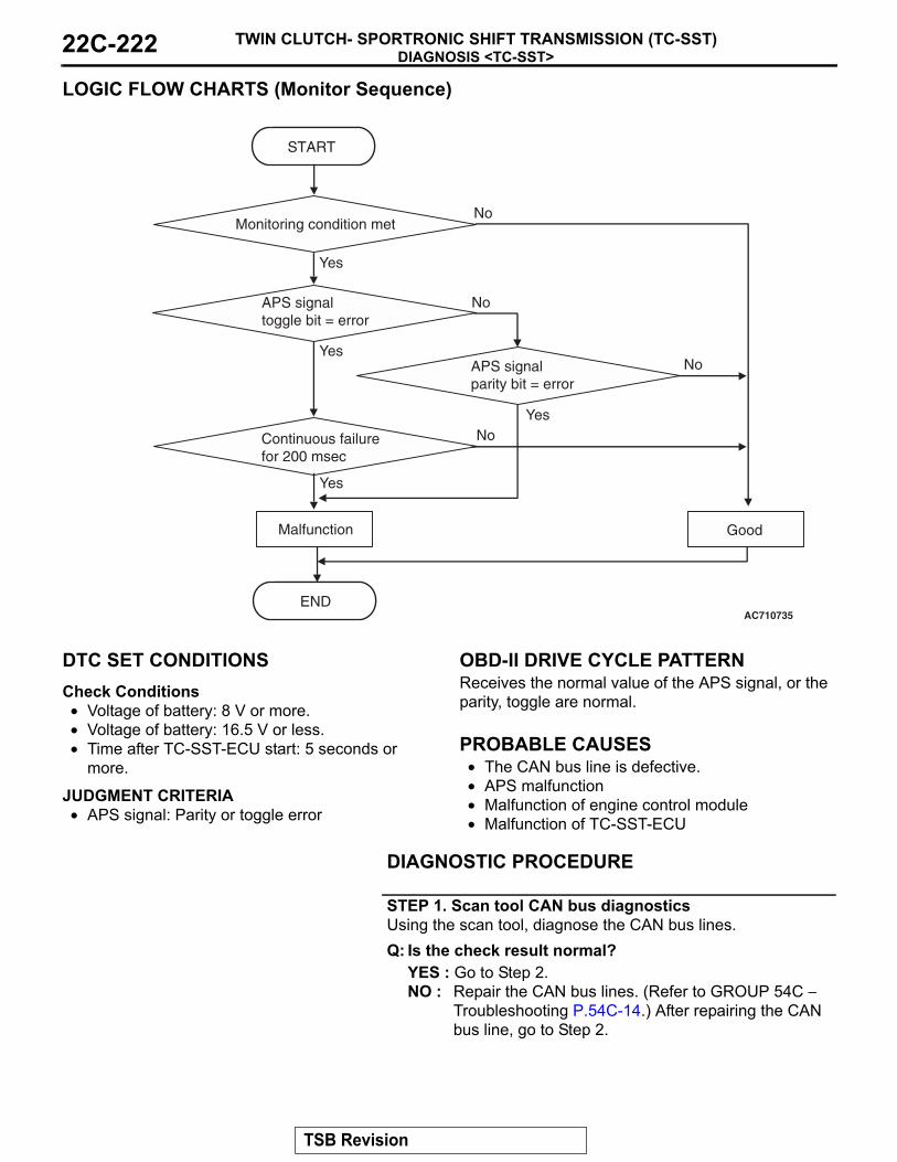
DIAGNOSIS <TC-SST>TWIN CLUTCH- SPORTRONIC SHIFT TRANSMISSION (TC-SST)22C-222
LOGIC FLOW CHARTS (Monitor Sequence)
.
DTC SET CONDITIONSCheck Conditions• Voltage of battery: 8 V or more.• Voltage of battery: 16.5 V or less.• Time after TC-SST-ECU start: 5 seconds or
more.
JUDGMENT CRITERIA• APS signal: Parity or toggle error
.
OBD-II DRIVE CYCLE PATTERNReceives the normal value of the APS signal, or the parity, toggle are normal..
PROBABLE CAUSES• The CAN bus line is defective.• APS malfunction• Malfunction of engine control module• Malfunction of TC-SST-ECU
DIAGNOSTIC PROCEDURE
STEP 1. Scan tool CAN bus diagnosticsUsing the scan tool, diagnose the CAN bus lines.Q: Is the check result normal?
YES : Go to Step 2.NO : Repair the CAN bus lines. (Refer to GROUP 54C −
Troubleshooting P.54C-14.) After repairing the CAN bus line, go to Step 2.
APS signal toggle bit = error
AC710735
START
No
Yes
Yes
No
GoodMalfunction
END
Monitoring condition met
No
Yes
APS signalparity bit = error
Continuous failurefor 200 msec
No
Yes
TSB Revision

DIAGNOSIS <TC-SST>TWIN CLUTCH- SPORTRONIC SHIFT TRANSMISSION (TC-SST) 22C-223
STEP 2. Scan tool diagnostic trouble codeCheck the engine diagnostic trouble code. (Refer to GROUP 13A − Troubleshooting P.13A-44.)Q: Is the DTC set?
YES : Perform the relevant troubleshooting.NO : Go to Step 3.
STEP 3. Check whether the DTC is reset.Q: Is DTC No. P1871 set?
YES : Replace the TC-SST assembly. (Refer to P.22C-341.)NO : Intermittent malfunction. (Refer to GROUP 00 − How
to Cope with Intermittent Malfunction P.00-15.)
DTC P1872: Between shift lever and TC-SST system (Q-A function abnormality)
CAUTION• If there is any problem in the CAN bus lines,
an incorrect diagnostic trouble code may be set. Prior to this diagnosis, diagnose the CAN bus lines.
• Whenever the ECU is replaced, ensure that the CAN bus lines are normal.
.
DIAGNOSTIC FUNCTIONTC-SST-ECU checks that the shift lever-ECU is nor-mal..
DESCRIPTIONS OF MONITOR METHODSThe shift lever-ECU is determined to be abnormal..
MONITOR EXECUTION• Continuous
.
MONITOR EXECUTION CONDITIONS (OTHER MONITOR AND SENSOR)Other Monitor (There is no temporary DTC stored
in memory for the item monitored below)• P0841: Clutch 1 pressure sensor system (Poor
performance)
• P0842: Clutch 1 pressure sensor system (Output low range out)
• P0843: Clutch 1 pressure sensor system (Output high range out)
• P0846: Clutch 2 pressure sensor system (Poor performance)
• P0847: Clutch 2 pressure sensor system (Output low range out)
• P0848: Clutch 2 pressure sensor system (Output high range out)
• P185D: Clutch open not possible• U0001: Bus off• U0100: Engine time-out error• P1803: Shift lever system (CAN or LIN time-out
error)• P1870: Engine torque signal abnormality• P1871: APS system (Signal abnormality)
Sensor (The sensor below is determined to be normal)
• Clutch 1 pressure sensor• Clutch 2 pressure sensor• APS• Shift lever-ECU
.
TSB Revision

DIAGNOSIS <TC-SST>TWIN CLUTCH- SPORTRONIC SHIFT TRANSMISSION (TC-SST)22C-224
LOGIC FLOW CHARTS (Monitor Sequence)
.
DTC SET CONDITIONSCheck Conditions• Voltage of battery: 8 V or more.• Voltage of battery: 16.5 V or less.• Time after TC-SST-ECU start: 5 seconds or
more.
JUDGMENT CRITERIA• Communication algorithm: Undesigned signal.
.
OBD-II DRIVE CYCLE PATTERNThe communication algorithm is normal..
PROBABLE CAUSES• Malfunction of the shift lever-ECU• Malfunction of TC-SST-ECU
DIAGNOSTIC PROCEDURE
STEP 1. Scan tool CAN bus diagnosticsUsing scan tool MB991958, diagnose the CAN bus lines.Q: Is the check result normal?
YES : Go to Step 2.NO : Repair the CAN bus lines. (Refer to GROUP 54C −
Troubleshooting P.54C-14.) After repairing the CAN bus line, go to Step 2.
STEP 2. Scan tool diagnostic trouble codeCheck the shift lever diagnostic trouble code. (Refer to P.22C-302.)Q: Is the DTC set?
YES : Perform the relevant troubleshooting.NO : Go to Step 3.
Question - Answeralgorithm = failed
AC710736
START
No
Yes
Yes
GoodMalfunction
END
Monitoring condition met
No
TSB Revision

DIAGNOSIS <TC-SST>TWIN CLUTCH- SPORTRONIC SHIFT TRANSMISSION (TC-SST) 22C-225
STEP 3. Replace the shift lever assembly, and check if the diagnostic trouble code is reset.(1) Replace the shift lever assembly. (Refer to P.22C-334.)(2) Check the DTC.Q: Is DTC No. P1872 set?
YES : Replace the TC-SST assembly. (Refer to P.22C-341.)NO : Intermittent malfunction. (Refer to GROUP 00 − How
to Cope with Intermittent Malfunction P.00-15.)
DTC P1873: Clutch 1 System (Pressure abnormality)
CAUTION• If there is any problem in the CAN bus lines,
an incorrect diagnostic trouble code may be set. Prior to this diagnosis, diagnose the CAN bus lines.
• Whenever the ECU is replaced, ensure that the CAN bus lines are normal.
.
DIAGNOSTIC FUNCTIONTC-SST-ECU checks that the clutch 1 pressure is normal..
DESCRIPTIONS OF MONITOR METHODSThe clutch 1 pressure is determined to be abnormal..
PROBABLE CAUSES• Malfunction of TC-SST-ECU• Malfunction of TC-SST clutch
DIAGNOSTIC PROCEDURE
STEP 1. Scan tool CAN bus diagnosticsUsing scan tool MB991958, diagnose the CAN bus lines.Q: Is the check result normal?
YES : Go to Step 2.NO : Repair the CAN bus lines. (Refer to GROUP 54C −
Troubleshooting P.54C-14.) After repairing the CAN bus line, go to Step 2.
STEP 2. Check whether the DTC is reset.Q: Is DTC No. P1873 set?
YES : Replace the TC-SST assembly. (Refer to P.22C-341.)NO : Intermittent malfunction. (Refer to GROUP 00 − How
to Cope with Intermittent Malfunction P.00-15.)
DTC P1874: Clutch 2 System (Pressure abnormality)
CAUTION• If there is any problem in the CAN bus lines,
an incorrect diagnostic trouble code may be set. Prior to this diagnosis, diagnose the CAN bus lines.
• Whenever the ECU is replaced, ensure that the CAN bus lines are normal.
.
DIAGNOSTIC FUNCTIONTC-SST-ECU checks that the clutch 2 pressure is normal..
TSB Revision

DIAGNOSIS <TC-SST>TWIN CLUTCH- SPORTRONIC SHIFT TRANSMISSION (TC-SST)22C-226
DESCRIPTIONS OF MONITOR METHODSThe clutch 2 pressure is determined to be abnormal..
PROBABLE CAUSES• Malfunction of TC-SST-ECU• Malfunction of TC-SST clutch
DIAGNOSTIC PROCEDURE
STEP 1. Scan tool CAN bus diagnosticsUsing scan tool MB991958, diagnose the CAN bus lines.Q: Is the check result normal?
YES : Go to Step 2.NO : Repair the CAN bus lines. (Refer to GROUP 54C −
Troubleshooting P.54C-14.) After repairing the CAN bus line, go to Step 2.
STEP 2. Check whether the DTC is reset.Q: Is DTC No. P1874 set?
YES : Replace the TC-SST assembly. (Refer to P.22C-341.)NO : Intermittent malfunction. (Refer to GROUP 00 − How
to Cope with Intermittent Malfunction P.00-15.)
DTC P1875: Damper Speed Sensor System (Poor performance)
CAUTION• If there is any problem in the CAN bus lines,
an incorrect diagnostic trouble code may be set. Prior to this diagnosis, diagnose the CAN bus lines.
• Whenever the ECU is replaced, ensure that the CAN bus lines are normal.
.
DIAGNOSTIC FUNCTIONTC-SST-ECU checks that the damper (closer to the engine than input shaft) is normal..
DESCRIPTIONS OF MONITOR METHODSThe damper speed sensor is determined to be abnormal..
MONITOR EXECUTION• Continuous
.
MONITOR EXECUTION CONDITIONS (OTHER MONITOR AND SENSOR)Other Monitor (There is no temporary DTC stored
in memory for the item monitored below)• P0715: Input shaft 1 (odd number gear axle)
speed sensor system (Output high range out)• P0716: Input shaft 1 (odd number gear axle)
speed sensor system (Poor performance)• P0717: Input shaft 1 (odd number gear axle)
speed sensor system (Output low range out)• P2766: Input shaft 2 (even number gear axle)
speed sensor system (Poor performance)
Sensor (The sensor below is determined to be normal)
• Input shaft 1 (odd number gear axle) speed sen-sor
• Input shaft 2 (even number gear axle) speed sen-sor
.
TSB Revision

DIAGNOSIS <TC-SST>TWIN CLUTCH- SPORTRONIC SHIFT TRANSMISSION (TC-SST) 22C-227
LOGIC FLOW CHARTS (Monitor Sequence)
.
AC710617
START
No
Yes
Yes
GoodMalfunction
END
Monitoring condition met
No
Continuous failurefor 400 msec
No
Yes
Sensor output speed> 16,000 r/min
TSB Revision

DIAGNOSIS <TC-SST>TWIN CLUTCH- SPORTRONIC SHIFT TRANSMISSION (TC-SST)22C-228
LOGIC FLOW CHARTS (Monitor Sequence)
.
DTC SET CONDITIONSCheck Conditions• Voltage of battery: 8 V or more.• Voltage of battery: 16.5 V or less.• Engine speed: 500 r/min or more.• Time since above engine condition: 400 millisec-
ond.
JUDGMENT CRITERIA• Sensor output speed: 16,000 r/min or more. (400
millisecond)• |"Engine speed via CAN" − "Sensor output
speed"|: 500 r/min or more. (500 millisecond)
.
OBD-II DRIVE CYCLE PATTERN• The output of the sensor remains 16,000 r/min or
less for 400 milliseconds.• The value of the |"Engine speed via CAN" − "Sen-
sor output speed"| remains 500 r/min or less for 500 milliseconds.
.
PROBABLE CAUSES• Malfunction of TC-SST-ECU
DIAGNOSTIC PROCEDURE
STEP 1. Scan tool CAN bus diagnosticsUsing scan tool MB991958, diagnose the CAN bus lines.Q: Is the check result normal?
YES : Go to Step 2.NO : Repair the CAN bus lines. (Refer to GROUP 54C −
Troubleshooting P.54C-14.) After repairing the CAN bus line, go to Step 2.
AC710618
START
No
Yes
Yes
GoodMalfunction
END
Monitoring condition met
No
Continuous failurefor 500 msec
No
Yes
|Engine speed (CAN)-sensor output speed|> 500 r/min
TSB Revision

DIAGNOSIS <TC-SST>TWIN CLUTCH- SPORTRONIC SHIFT TRANSMISSION (TC-SST) 22C-229
STEP 2. Check whether the DTC is reset.Q: Is DTC No. P1875 set?
YES : Replace the TC-SST assembly. (Refer to P.22C-341.)NO : Intermittent malfunction. (Refer to GROUP 00 − How
to Cope with Intermittent Malfunction P.00-15.)
DTC P1876: 1st Gear Block
CAUTION• If there is any problem in the CAN bus lines,
an incorrect diagnostic trouble code may be set. Prior to this diagnosis, diagnose the CAN bus lines.
• Whenever the ECU is replaced, ensure that the CAN bus lines are normal.
.
DIAGNOSTIC FUNCTIONTC-SST-ECU checks that the gear engagement is normal..
DESCRIPTIONS OF MONITOR METHODSThe engagement of the 1st gear is determined to be impossible.
.
MONITOR EXECUTION• Continuous
.
MONITOR EXECUTION CONDITIONS (OTHER MONITOR AND SENSOR)Other Monitor (There is no temporary DTC stored
in memory for the item monitored below)• Not applicable
Sensor (The sensor below is determined to be normal)
• Not applicable.
LOGIC FLOW CHARTS (Monitor Sequence)
.
AC710729
START
No
GoodMalfunction
END
Yes
Yes
Monitoring condition met
NoGear (synchro) engagementis 3 times blocked
TSB Revision

DIAGNOSIS <TC-SST>TWIN CLUTCH- SPORTRONIC SHIFT TRANSMISSION (TC-SST)22C-230
DTC SET CONDITIONSCheck Conditions• Engine speed: 500 r/min or more.• Time since above engine condition: 400 millisec-
ond or more.• Target gear: 1st gear.
JUDGMENT CRITERIA• Gear (synchro) engagement: 3 times blocked.
(immediately).
OBD-II DRIVE CYCLE PATTERNThe 1st gear is engaged..
PROBABLE CAUSES• Malfunction of TC-SST-ECU• Malfunction of TC-SST gear
DIAGNOSTIC PROCEDURE
STEP 1. Scan tool CAN bus diagnosticsUsing scan tool MB991958, diagnose the CAN bus lines.Q: Is the check result normal?
YES : Go to Step 2.NO : Repair the CAN bus lines. (Refer to GROUP 54C −
Troubleshooting P.54C-14.) After repairing the CAN bus line, go to Step 2.
STEP 2. Check whether the DTC is reset.Q: Is DTC No. P1876 set?
YES : Replace the TC-SST assembly. (Refer to P.22C-341.)NO : Intermittent malfunction. (Refer to GROUP 00 − How
to Cope with Intermittent Malfunction P.00-15.)
DTC P1877: Gear Block 2nd Gear
CAUTION• If there is any problem in the CAN bus lines,
an incorrect diagnostic trouble code may be set. Prior to this diagnosis, diagnose the CAN bus lines.
• Whenever the ECU is replaced, ensure that the CAN bus lines are normal.
.
DIAGNOSTIC FUNCTIONTC-SST-ECU checks that the gear engagement is normal..
DESCRIPTIONS OF MONITOR METHODSThe engagement of the 2nd gear is determined to be impossible.
.
MONITOR EXECUTION• Continuous
.
MONITOR EXECUTION CONDITIONS (OTHER MONITOR AND SENSOR)Other Monitor (There is no temporary DTC stored
in memory for the item monitored below)• Not applicable
Sensor (The sensor below is determined to be normal)
• Not applicable.
TSB Revision

DIAGNOSIS <TC-SST>TWIN CLUTCH- SPORTRONIC SHIFT TRANSMISSION (TC-SST) 22C-231
LOGIC FLOW CHARTS (Monitor Sequence)
.
DTC SET CONDITIONSCheck Conditions• Engine speed: 500 r/min or more.• Time since above engine condition: 400 millisec-
ond or more.• Target gear: 2nd gear.
JUDGMENT CRITERIA• Gear (synchro) engagement: 3 times blocked.
(immediately)
.
OBD-II DRIVE CYCLE PATTERNThe 2nd gear is engaged..
PROBABLE CAUSES• Malfunction of TC-SST-ECU• Malfunction of TC-SST gear
DIAGNOSTIC PROCEDURE
STEP 1. Scan tool CAN bus diagnosticsUsing scan tool MB991958, diagnose the CAN bus lines.Q: Is the check result normal?
YES : Go to Step 2.NO : Repair the CAN bus lines. (Refer to GROUP 54C −
Troubleshooting P.54C-14.) After repairing the CAN bus line, go to Step 2.
STEP 2. Check whether the DTC is reset.Q: Is DTC No. P1877 set?
YES : Replace the TC-SST assembly. (Refer to P.22C-341.)NO : Intermittent malfunction. (Refer to GROUP 00 − How
to Cope with Intermittent Malfunction P.00-15.)
AC710729
START
No
GoodMalfunction
END
Yes
Yes
Monitoring condition met
NoGear (synchro) engagementis 3 times blocked
TSB Revision

DIAGNOSIS <TC-SST>TWIN CLUTCH- SPORTRONIC SHIFT TRANSMISSION (TC-SST)22C-232
DTC P1878: Gear Block 3rd Gear
CAUTION• If there is any problem in the CAN bus lines,
an incorrect diagnostic trouble code may be set. Prior to this diagnosis, diagnose the CAN bus lines.
• Whenever the ECU is replaced, ensure that the CAN bus lines are normal.
.
DIAGNOSTIC FUNCTIONTC-SST-ECU checks that the gear engagement is normal..
DESCRIPTIONS OF MONITOR METHODSThe engagement of the 3rd gear is determined to be impossible.
.
MONITOR EXECUTION• Continuous
.
MONITOR EXECUTION CONDITIONS (OTHER MONITOR AND SENSOR)Other Monitor (There is no temporary DTC stored
in memory for the item monitored below)• Not applicable
Sensor (The sensor below is determined to be normal)
• Not applicable.
LOGIC FLOW CHARTS (Monitor Sequence)
.
DTC SET CONDITIONSCheck Conditions• Engine speed: 500 r/min or more.• Time since above engine condition: 400 millisec-
ond or more.• Target gear: 3rd gear.
JUDGMENT CRITERIA• Gear (synchro) engagement: 3 times blocked.
(immediately).
OBD-II DRIVE CYCLE PATTERNThe 3rd gear is engaged..
AC710729
START
No
GoodMalfunction
END
Yes
Yes
Monitoring condition met
NoGear (synchro) engagementis 3 times blocked
TSB Revision

DIAGNOSIS <TC-SST>TWIN CLUTCH- SPORTRONIC SHIFT TRANSMISSION (TC-SST) 22C-233
PROBABLE CAUSES• Malfunction of TC-SST-ECU• Malfunction of TC-SST gear
DIAGNOSTIC PROCEDURE
STEP 1. Scan tool CAN bus diagnosticsUsing scan tool MB991958, diagnose the CAN bus lines.Q: Is the check result normal?
YES : Go to Step 2.NO : Repair the CAN bus lines. (Refer to GROUP 54C −
Troubleshooting P.54C-14.) After repairing the CAN bus line, go to Step 2.
STEP 2. Check whether the DTC is reset.Q: Is DTC No. P1878 set?
YES : Replace the TC-SST assembly. (Refer to P.22C-341.)NO : Intermittent malfunction. (Refer to GROUP 00 − How
to Cope with Intermittent Malfunction P.00-15.)
DTC P1879: Gear Block 4th Gear
CAUTION• If there is any problem in the CAN bus lines,
an incorrect diagnostic trouble code may be set. Prior to this diagnosis, diagnose the CAN bus lines.
• Whenever the ECU is replaced, ensure that the CAN bus lines are normal.
.
DIAGNOSTIC FUNCTIONTC-SST-ECU checks that the gear engagement is normal..
DESCRIPTIONS OF MONITOR METHODSThe engagement of the 4th gear is determined to be impossible.
.
MONITOR EXECUTION• Continuous
.
MONITOR EXECUTION CONDITIONS (OTHER MONITOR AND SENSOR)Other Monitor (There is no temporary DTC stored
in memory for the item monitored below)• Not applicable
Sensor (The sensor below is determined to be normal)
• Not applicable.
TSB Revision
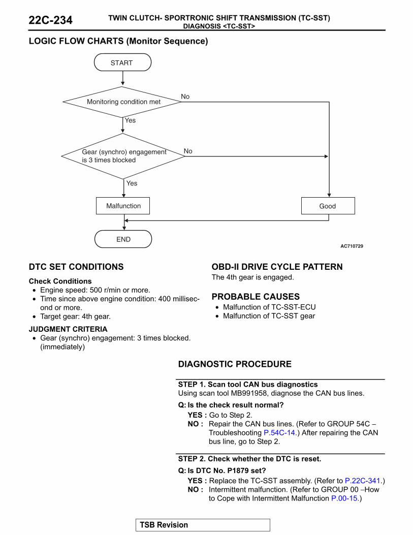
DIAGNOSIS <TC-SST>TWIN CLUTCH- SPORTRONIC SHIFT TRANSMISSION (TC-SST)22C-234
LOGIC FLOW CHARTS (Monitor Sequence)
.
DTC SET CONDITIONSCheck Conditions• Engine speed: 500 r/min or more.• Time since above engine condition: 400 millisec-
ond or more.• Target gear: 4th gear.
JUDGMENT CRITERIA• Gear (synchro) engagement: 3 times blocked.
(immediately)
.
OBD-II DRIVE CYCLE PATTERNThe 4th gear is engaged..
PROBABLE CAUSES• Malfunction of TC-SST-ECU• Malfunction of TC-SST gear
DIAGNOSTIC PROCEDURE
STEP 1. Scan tool CAN bus diagnosticsUsing scan tool MB991958, diagnose the CAN bus lines.Q: Is the check result normal?
YES : Go to Step 2.NO : Repair the CAN bus lines. (Refer to GROUP 54C −
Troubleshooting P.54C-14.) After repairing the CAN bus line, go to Step 2.
STEP 2. Check whether the DTC is reset.Q: Is DTC No. P1879 set?
YES : Replace the TC-SST assembly. (Refer to P.22C-341.)NO : Intermittent malfunction. (Refer to GROUP 00 − How
to Cope with Intermittent Malfunction P.00-15.)
AC710729
START
No
GoodMalfunction
END
Yes
Yes
Monitoring condition met
NoGear (synchro) engagementis 3 times blocked
TSB Revision

DIAGNOSIS <TC-SST>TWIN CLUTCH- SPORTRONIC SHIFT TRANSMISSION (TC-SST) 22C-235
DTC P187A: Gear Block 5th Gear
CAUTION• If there is any problem in the CAN bus lines,
an incorrect diagnostic trouble code may be set. Prior to this diagnosis, diagnose the CAN bus lines.
• Whenever the ECU is replaced, ensure that the CAN bus lines are normal.
.
DIAGNOSTIC FUNCTIONTC-SST-ECU checks that the gear engagement is normal..
DESCRIPTIONS OF MONITOR METHODSThe engagement of the 5th gear is determined to be impossible.
.
MONITOR EXECUTION• Continuous
.
MONITOR EXECUTION CONDITIONS (OTHER MONITOR AND SENSOR)Other Monitor (There is no temporary DTC stored
in memory for the item monitored below)• Not applicable
Sensor (The sensor below is determined to be normal)
• Not applicable.
LOGIC FLOW CHARTS (Monitor Sequence)
.
DTC SET CONDITIONSCheck Conditions• Engine speed: 500 r/min or more.• Time since above engine condition: 400 millisec-
ond or more.• Target gear: 5th gear.
JUDGMENT CRITERIA• Gear (synchro) engagement: 3 times blocked.
(immediately).
OBD-II DRIVE CYCLE PATTERNThe 5th gear is engaged..
AC710729
START
No
GoodMalfunction
END
Yes
Yes
Monitoring condition met
NoGear (synchro) engagementis 3 times blocked
TSB Revision

DIAGNOSIS <TC-SST>TWIN CLUTCH- SPORTRONIC SHIFT TRANSMISSION (TC-SST)22C-236
PROBABLE CAUSES• Malfunction of TC-SST-ECU• Malfunction of TC-SST gear
DIAGNOSTIC PROCEDURE
STEP 1. Scan tool CAN bus diagnosticsUsing scan tool MB991958, diagnose the CAN bus lines.Q: Is the check result normal?
YES : Go to Step 2.NO : Repair the CAN bus lines. (Refer to GROUP 54C −
Troubleshooting P.54C-14.) After repairing the CAN bus line, go to Step 2.
STEP 2. Check whether the DTC is reset.Q: Is DTC No. P187A set?
YES : Replace the TC-SST assembly. (Refer to P.22C-341.)NO : Intermittent malfunction. (Refer to GROUP 00 − How
to Cope with Intermittent Malfunction P.00-15.)
DTC P187B: Gear Block 6th Gear
CAUTION• If there is any problem in the CAN bus lines,
an incorrect diagnostic trouble code may be set. Prior to this diagnosis, diagnose the CAN bus lines.
• Whenever the ECU is replaced, ensure that the CAN bus lines are normal.
.
DIAGNOSTIC FUNCTIONTC-SST-ECU checks that the gear engagement is normal..
DESCRIPTIONS OF MONITOR METHODSThe engagement of the 6th gear is determined to be impossible.
.
MONITOR EXECUTION• Continuous
.
MONITOR EXECUTION CONDITIONS (OTHER MONITOR AND SENSOR)Other Monitor (There is no temporary DTC stored
in memory for the item monitored below)• Not applicable
Sensor (The sensor below is determined to be normal)
• Not applicable.
TSB Revision

DIAGNOSIS <TC-SST>TWIN CLUTCH- SPORTRONIC SHIFT TRANSMISSION (TC-SST) 22C-237
LOGIC FLOW CHARTS (Monitor Sequence)
.
DTC SET CONDITIONSCheck Conditions• Engine speed: 500 r/min or more.• Time since above engine condition: 400 millisec-
ond or more.• Target gear: 6th gear.
JUDGMENT CRITERIA• Gear (synchro) engagement: 3 times blocked.
(immediately)
.
OBD-II DRIVE CYCLE PATTERNThe 6th gear is engaged..
PROBABLE CAUSES• Malfunction of TC-SST-ECU• Malfunction of TC-SST gear
DIAGNOSTIC PROCEDURE
STEP 1. Scan tool CAN bus diagnosticsUsing scan tool MB991958, diagnose the CAN bus lines.Q: Is the check result normal?
YES : Go to Step 2.NO : Repair the CAN bus lines. (Refer to GROUP 54C −
Troubleshooting P.54C-14.) After repairing the CAN bus line, go to Step 2.
STEP 2. Check whether the DTC is reset.Q: Is DTC No. P187B set?
YES : Replace the TC-SST assembly. (Refer to P.22C-341.)NO : Intermittent malfunction. (Refer to GROUP 00 − How
to Cope with Intermittent Malfunction P.00-15.)
AC710729
START
No
GoodMalfunction
END
Yes
Yes
Monitoring condition met
NoGear (synchro) engagementis 3 times blocked
TSB Revision

DIAGNOSIS <TC-SST>TWIN CLUTCH- SPORTRONIC SHIFT TRANSMISSION (TC-SST)22C-238
DTC P187C: Gear Block Reverse Gear
CAUTION• If there is any problem in the CAN bus lines,
an incorrect diagnostic trouble code may be set. Prior to this diagnosis, diagnose the CAN bus lines.
• Whenever the ECU is replaced, ensure that the CAN bus lines are normal.
.
DIAGNOSTIC FUNCTIONTC-SST-ECU checks that the gear engagement is normal..
DESCRIPTIONS OF MONITOR METHODSThe engagement of the reverse gear is determined to be impossible.
.
MONITOR EXECUTION• Continuous
.
MONITOR EXECUTION CONDITIONS (OTHER MONITOR AND SENSOR)Other Monitor (There is no temporary DTC stored
in memory for the item monitored below)• Not applicable
Sensor (The sensor below is determined to be normal)
• Not applicable.
LOGIC FLOW CHARTS (Monitor Sequence)
.
DTC SET CONDITIONSCheck Conditions• Engine speed: 500 r/min or more.• Time since above engine condition: 400 millisec-
ond or more.• Target gear: Reverse gear.
JUDGMENT CRITERIA• Gear (synchro) engagement: 3 times blocked.
(immediately).
OBD-II DRIVE CYCLE PATTERNThe reverse gear is engaged..
AC710729
START
No
GoodMalfunction
END
Yes
Yes
Monitoring condition met
NoGear (synchro) engagementis 3 times blocked
TSB Revision

DIAGNOSIS <TC-SST>TWIN CLUTCH- SPORTRONIC SHIFT TRANSMISSION (TC-SST) 22C-239
PROBABLE CAUSES• Malfunction of TC-SST-ECU• Malfunction of TC-SST gear
DIAGNOSTIC PROCEDURE
STEP 1. Scan tool CAN bus diagnosticsUsing scan tool MB991958, diagnose the CAN bus lines.Q: Is the check result normal?
YES : Go to Step 2.NO : Repair the CAN bus lines. (Refer to GROUP 54C −
Troubleshooting P.54C-14.) After repairing the CAN bus line, go to Step 2.
STEP 2. Check whether the DTC is reset.Q: Is DTC No. P187C set?
YES : Replace the TC-SST assembly. (Refer to P.22C-341.)NO : Intermittent malfunction. (Refer to GROUP 00 − How
to Cope with Intermittent Malfunction P.00-15.)
DTC P1880: EOL Mode Active
CAUTION• If there is any problem in the CAN bus lines,
an incorrect diagnostic trouble code may be set. Prior to this diagnosis, diagnose the CAN bus lines.
• Whenever the ECU is replaced, ensure that the CAN bus lines are normal.
.
DIAGNOSTIC FUNCTIONTC-SST-ECU checks that the TC-SST setting mode is normal.
.
DESCRIPTIONS OF MONITOR METHODSThe TC-SST setting mode is determined to be EOL (end of line) mode..
PROBABLE CAUSES• The setting mode changeover mistake when
TC-SST is shipped.• Malfunction of TC-SST-ECU
DIAGNOSTIC PROCEDURE
STEP 1. Scan tool CAN bus diagnosticsUsing scan tool MB991958, diagnose the CAN bus lines.Q: Is the check result normal?
YES : Go to Step 2.NO : Repair the CAN bus lines. (Refer to GROUP 54C −
Troubleshooting P.54C-14.) After repairing the CAN bus line, go to Step 2.
STEP 2. Check whether the DTC is reset.Q: Is DTC No. P1880 set?
YES : Replace the TC-SST assembly. (Refer to P.22C-341.)NO : Intermittent malfunction. (Refer to GROUP 00 − How
to Cope with Intermittent Malfunction P.00-15.)
TSB Revision

DIAGNOSIS <TC-SST>TWIN CLUTCH- SPORTRONIC SHIFT TRANSMISSION (TC-SST)22C-240
DTC P1881: Twin clutch SST control mode switch system (Malfunction)
CAUTION• If there is any problem in the CAN bus lines,
an incorrect diagnostic trouble code may be set. Prior to this diagnosis, diagnose the CAN bus lines.
• Whenever the ECU is replaced, ensure that the CAN bus lines are normal.
.
DIAGNOSTIC FUNCTIONTC-SST-ECU checks that the twin clutch SST control mode switch is normal.
.
DESCRIPTIONS OF MONITOR METHODS"+" and "−" signals of the twin clutch SST control mode switch is determined to be stuck on..
PROBABLE CAUSES• Twin clutch SST control mode switch malfunction• Malfunction of TC-SST-ECU
DIAGNOSTIC PROCEDURE
STEP 1. Scan tool CAN bus diagnosticsUsing scan tool MB991958, diagnose the CAN bus lines.Q: Is the check result normal?
YES : Go to Step 2.NO : Repair the CAN bus lines. (Refer to GROUP 54C −
Troubleshooting P.54C-14.) After repairing the CAN bus line, go to Step 2.
STEP 2. Check whether the DTC is reset.Q: Is DTC No. P1881 set?
YES : Go to Step 3.NO : Intermittent malfunction. (Refer to GROUP 00 − How
to Cope with Intermittent Malfunction P.00-15.)
STEP 3. Twin clutch SST control mode switch checkRefer to P.22C-349.Q: Is the check result normal?
YES : Go to Step 4.NO : Replace the twin clutch SST control mode
switch.(Refer to P.22C-349.)
STEP 4. Shift lever assembly replacement(1) Replace the shift lever assembly. (Refer to P.22C-334.)(2) Check if the DTC is set.Q: Is DTC No. P1881 set?
YES : Replace the TC-SST assembly. (Refer to P.22C-341.)NO : Intermittent malfunction. (Refer to GROUP 00 − How
to Cope with Intermittent Malfunction P.00-15.)
TSB Revision

DIAGNOSIS <TC-SST>TWIN CLUTCH- SPORTRONIC SHIFT TRANSMISSION (TC-SST) 22C-241
DTC P2718: Clutch/Shift Pressure Solenoid 1 System (Open circuit)
CAUTION• If there is any problem in the CAN bus lines,
an incorrect diagnostic trouble code may be set. Prior to this diagnosis, diagnose the CAN bus lines.
• Whenever the ECU is replaced, ensure that the CAN bus lines are normal.
.
DIAGNOSTIC FUNCTIONTC-SST-ECU checks that the clutch/shift pressure solenoid 1 circuit is normal..
DESCRIPTIONS OF MONITOR METHODSThe clutch/shift pressure solenoid 1 circuit is deter-mined to be open..
MONITOR EXECUTION• Continuous
.
MONITOR EXECUTION CONDITIONS (OTHER MONITOR AND SENSOR)Other Monitor (There is no temporary DTC stored
in memory for the item monitored below)• P0841: Clutch 1 pressure sensor system (Poor
performance)
• P0842: Clutch 1 pressure sensor system (Output low range out)
• P0843: Clutch 1 pressure sensor system (Output high range out)
• P2733: Clutch/shift switching solenoid 1, spool stuck
• P2736: Clutch/shift switching solenoid 1 system (Open circuit)
• P2738: Clutch/shift switching solenoid 1 system (Short to ground)
• P2739: Clutch/shift switching solenoid 1 system (Short to power supply)
• P181B: Clutch 1 (Pressure low range out)• P181C: Clutch 1 (Pressure high range out)• P1859: Disengagement too late with clutch 1
Sensor (The sensor below is determined to be normal)
• Clutch 1 pressure sensor• Clutch/shift switching solenoid 1
.
TSB Revision

DIAGNOSIS <TC-SST>TWIN CLUTCH- SPORTRONIC SHIFT TRANSMISSION (TC-SST)22C-242
LOGIC FLOW CHARTS (Monitor Sequence)
.
DTC SET CONDITIONSCheck Conditions• Voltage of battery: 8 V or more.• Voltage of battery: 16.5 V or less.
JUDGMENT CRITERIA• FET (Field Effect Transistor) output: 1 V or more.
(400 millisecond)
.
OBD-II DRIVE CYCLE PATTERNThe FET channel output remains 1 V or less for 400 milliseconds..
PROBABLE CAUSES• Malfunction of TC-SST-ECU
DIAGNOSTIC PROCEDURE
STEP 1. Scan tool CAN bus diagnosticsUsing scan tool MB991958, diagnose the CAN bus lines.Q: Is the check result normal?
YES : Go to Step 2.NO : Repair the CAN bus lines. (Refer to GROUP 54C −
Troubleshooting P.54C-14.) After repairing the CAN bus line, go to Step 2.
STEP 2. Check whether the DTC is reset.Q: Is DTC No. P2718 set?
YES : Replace the TC-SST assembly. (Refer to P.22C-341.)NO : Intermittent malfunction. (Refer to GROUP 00 − How
to Cope with Intermittent Malfunction P.00-15.)
AC710656
START
No
Yes
GoodMalfunction
END
Monitoring condition met
Continuous failurefor 400 msec
No
Yes
No
Yes
FET* output > 1 V
*FET : Field Effect Transistor
TSB Revision

DIAGNOSIS <TC-SST>TWIN CLUTCH- SPORTRONIC SHIFT TRANSMISSION (TC-SST) 22C-243
DTC P2719: Clutch/Shift Pressure Solenoid 1 System (Overcurrent)
CAUTION• If there is any problem in the CAN bus lines,
an incorrect diagnostic trouble code may be set. Prior to this diagnosis, diagnose the CAN bus lines.
• Whenever the ECU is replaced, ensure that the CAN bus lines are normal.
.
DIAGNOSTIC FUNCTIONTC-SST-ECU checks that the clutch/shift pressure solenoid 1 circuit is normal..
DESCRIPTIONS OF MONITOR METHODSThe supply current to the clutch/shift pressure sole-noid 1 is determined to be overcurrent..
MONITOR EXECUTION• Continuous
.
MONITOR EXECUTION CONDITIONS (OTHER MONITOR AND SENSOR)Other Monitor (There is no temporary DTC stored
in memory for the item monitored below)• P0841: Clutch 1 pressure sensor system (Poor
performance)
• P0842: Clutch 1 pressure sensor system (Output low range out)
• P0843: Clutch 1 pressure sensor system (Output high range out)
• P2733: Clutch/shift switching solenoid 1, spool stuck
• P2736: Clutch/shift switching solenoid 1 system (Open circuit)
• P2738: Clutch/shift switching solenoid 1 system (Short to ground)
• P2739: Clutch/shift switching solenoid 1 system (Short to power supply)
• P181B: Clutch 1 (Pressure low range out)• P181C: Clutch 1 (Pressure high range out)• P1859: Disengagement too late with clutch 1
Sensor (The sensor below is determined to be normal)
• Clutch 1 pressure sensor• Clutch/shift switching solenoid 1
.
TSB Revision

DIAGNOSIS <TC-SST>TWIN CLUTCH- SPORTRONIC SHIFT TRANSMISSION (TC-SST)22C-244
LOGIC FLOW CHARTS (Monitor Sequence)
.
DTC SET CONDITIONSCheck Conditions• Voltage of battery: 8 V or more.• Voltage of battery: 16.5 V or less.• Engine speed: 500 r/min or more.• Time since above engine condition: 400 millisec-
ond or more.
JUDGMENT CRITERIA• FET (Field Effect Transistor) current: 3.5 A or
more, and FET (Field Effect Transistor) output: 100 mV or less. (300 millisecond)
.
OBD-II DRIVE CYCLE PATTERNThe status with the current of the FET channel shunt 3.5 A or less and with the FET channel output 100 mV or more continues for 300 milliseconds..
PROBABLE CAUSES• Malfunction of TC-SST-ECU
AC710657
START
No
Yes
GoodMalfunction
END
Monitoring condition met
Continuous failurefor 300 msec
No
Yes
No
Yes
Yes
FET* output < 100 mV
FET* current > 3.5 A
No
*FET : Field Effect Transistor
TSB Revision

DIAGNOSIS <TC-SST>TWIN CLUTCH- SPORTRONIC SHIFT TRANSMISSION (TC-SST) 22C-245
DIAGNOSTIC PROCEDURE
STEP 1. Scan tool CAN bus diagnosticsUsing scan tool MB991958, diagnose the CAN bus lines.Q: Is the check result normal?
YES : Go to Step 2.NO : Repair the CAN bus lines. (Refer to GROUP 54C −
Troubleshooting P.54C-14.) After repairing the CAN bus line, go to Step 2.
STEP 2. Check whether the DTC is reset.Q: Is DTC No. P2719 set?
YES : Replace the TC-SST assembly. (Refer to P.22C-341.)NO : Intermittent malfunction. (Refer to GROUP 00 − How
to Cope with Intermittent Malfunction P.00-15.)
DTC P2720: Clutch/Shift Pressure Solenoid 1 System (Short to ground)
CAUTION• If there is any problem in the CAN bus lines,
an incorrect diagnostic trouble code may be set. Prior to this diagnosis, diagnose the CAN bus lines.
• Whenever the ECU is replaced, ensure that the CAN bus lines are normal.
.
DIAGNOSTIC FUNCTIONTC-SST-ECU checks that the clutch/shift pressure solenoid 1 circuit is normal..
DESCRIPTIONS OF MONITOR METHODSThe clutch/shift pressure solenoid 1 circuit is deter-mined to be short to ground..
MONITOR EXECUTION• Continuous
.
MONITOR EXECUTION CONDITIONS (OTHER MONITOR AND SENSOR)Other Monitor (There is no temporary DTC stored
in memory for the item monitored below)• P0841: Clutch 1 pressure sensor system (Poor
performance)
• P0842: Clutch 1 pressure sensor system (Output low range out)
• P0843: Clutch 1 pressure sensor system (Output high range out)
• P2733: Clutch/shift switching solenoid 1, spool stuck
• P2736: Clutch/shift switching solenoid 1 system (Open circuit)
• P2738: Clutch/shift switching solenoid 1 system (Short to ground)
• P2739: Clutch/shift switching solenoid 1 system (Short to power supply)
• P181B: Clutch 1 (Pressure low range out)• P181C: Clutch 1 (Pressure high range out)• P1859: Disengagement too late with clutch 1
Sensor (The sensor below is determined to be normal)
• Clutch 1 pressure sensor• Clutch/shift switching solenoid 1
.
TSB Revision

DIAGNOSIS <TC-SST>TWIN CLUTCH- SPORTRONIC SHIFT TRANSMISSION (TC-SST)22C-246
LOGIC FLOW CHARTS (Monitor Sequence)
.
DTC SET CONDITIONSCheck Conditions• Voltage of battery: 8 V or more.• Voltage of battery: 16.5 V or less.
JUDGMENT CRITERIA• FET (Field Effect Transistor) output: 100 mV or
less. (400 millisecond)
.
OBD-II DRIVE CYCLE PATTERNThe FET channel output remains 100 mV or more for 400 milliseconds..
PROBABLE CAUSES• Malfunction of TC-SST-ECU
DIAGNOSTIC PROCEDURE
STEP 1. Scan tool CAN bus diagnosticsUsing scan tool MB991958, diagnose the CAN bus lines.Q: Is the check result normal?
YES : Go to Step 2.NO : Repair the CAN bus lines. (Refer to GROUP 54C −
Troubleshooting P.54C-14.) After repairing the CAN bus line, go to Step 2.
STEP 2. Check whether the DTC is reset.Q: Is DTC No. P2720 set?
YES : Replace the TC-SST assembly. (Refer to P.22C-341.)NO : Intermittent malfunction. (Refer to GROUP 00 − How
to Cope with Intermittent Malfunction P.00-15.)
AC710658
START
No
GoodMalfunction
END
Monitoring condition met
Continuous failurefor 400 msec
No
Yes
Yes
Yes
FET* output < 100 mVNo
*FET : Field Effect Transistor
TSB Revision

DIAGNOSIS <TC-SST>TWIN CLUTCH- SPORTRONIC SHIFT TRANSMISSION (TC-SST) 22C-247
DTC P2721: Clutch/Shift Pressure Solenoid 1 System (Short to power supply)
CAUTION• If there is any problem in the CAN bus lines,
an incorrect diagnostic trouble code may be set. Prior to this diagnosis, diagnose the CAN bus lines.
• Whenever the ECU is replaced, ensure that the CAN bus lines are normal.
.
DIAGNOSTIC FUNCTIONTC-SST-ECU checks that the clutch/shift pressure solenoid 1 circuit is normal..
DESCRIPTIONS OF MONITOR METHODSThe clutch/shift pressure solenoid 1 circuit is deter-mined to be short to power supply..
MONITOR EXECUTION• Continuous
.
MONITOR EXECUTION CONDITIONS (OTHER MONITOR AND SENSOR)Other Monitor (There is no temporary DTC stored
in memory for the item monitored below)• P0841: Clutch 1 pressure sensor system (Poor
performance)
• P0842: Clutch 1 pressure sensor system (Output low range out)
• P0843: Clutch 1 pressure sensor system (Output high range out)
• P2733: Clutch/shift switching solenoid 1, spool stuck
• P2736: Clutch/shift switching solenoid 1 system (Open circuit)
• P2738: Clutch/shift switching solenoid 1 system (Short to ground)
• P2739: Clutch/shift switching solenoid 1 system (Short to power supply)
• P181B: Clutch 1 (Pressure low range out)• P181C: Clutch 1 (Pressure high range out)• P1859: Disengagement too late with clutch 1
Sensor (The sensor below is determined to be normal)
• Clutch 1 pressure sensor• Clutch/shift switching solenoid 1
.
TSB Revision

DIAGNOSIS <TC-SST>TWIN CLUTCH- SPORTRONIC SHIFT TRANSMISSION (TC-SST)22C-248
LOGIC FLOW CHARTS (Monitor Sequence)
.
DTC SET CONDITIONSCheck Conditions• Voltage of battery: 8 V or more.• Voltage of battery: 16.5 V or less.• Clutch/shift pressure solenoid 1: OFF.
JUDGMENT CRITERIA• FET (Field Effect Transistor) output: (Battery volt-
age − 2 V) or more. (160 millisecond)
.
OBD-II DRIVE CYCLE PATTERNThe FET channel output remains the battery voltage − 2 V or less for 160 milliseconds..
PROBABLE CAUSES• Malfunction of TC-SST-ECU
DIAGNOSTIC PROCEDURE
STEP 1. Scan tool CAN bus diagnosticsUsing scan tool MB991958, diagnose the CAN bus lines.Q: Is the check result normal?
YES : Go to Step 2.NO : Repair the CAN bus lines. (Refer to GROUP 54C −
Troubleshooting P.54C-14.) After repairing the CAN bus line, go to Step 2.
AC710659
START
No
GoodMalfunction
END
Monitoring condition met
Continuous failurefor 160 msec
No
Yes
Yes
Yes
FET* output> Battery voltage - 2V
No
*FET : Field Effect Transistor
TSB Revision

DIAGNOSIS <TC-SST>TWIN CLUTCH- SPORTRONIC SHIFT TRANSMISSION (TC-SST) 22C-249
STEP 2. Check whether the DTC is reset.Q: Is DTC No. P2721 set?
YES : Replace the TC-SST assembly. (Refer to P.22C-341.)NO : Intermittent malfunction. (Refer to GROUP 00 − How
to Cope with Intermittent Malfunction P.00-15.)
DTC P2727: Clutch/Shift Pressure Solenoid 2 System (Open circuit)
CAUTION• If there is any problem in the CAN bus lines,
an incorrect diagnostic trouble code may be set. Prior to this diagnosis, diagnose the CAN bus lines.
• Whenever the ECU is replaced, ensure that the CAN bus lines are normal.
.
DIAGNOSTIC FUNCTIONTC-SST-ECU checks that the clutch/shift pressure solenoid 2 circuit is normal..
DESCRIPTIONS OF MONITOR METHODSThe clutch/shift pressure solenoid 2 circuit is deter-mined to be open..
MONITOR EXECUTION• Continuous
.
MONITOR EXECUTION CONDITIONS (OTHER MONITOR AND SENSOR)Other Monitor (There is no temporary DTC stored
in memory for the item monitored below)• P0846: Clutch 2 pressure sensor system (Poor
performance)
• P0847: Clutch 2 pressure sensor system (Output low range out)
• P0848: Clutch 2 pressure sensor system (Output high range out)
• P2809: Clutch/shift switching solenoid 2, spool stuck
• P2812: Clutch/shift switching solenoid 2 system (Open circuit)
• P2814: Clutch/shift switching solenoid 2 system (Short to ground)
• P2815: Clutch/shift switching solenoid 2 system (Short to power supply)
• P181B: Clutch 1 (Pressure low range out)• P181C: Clutch 1 (Pressure high range out)• P1859: Disengagement too late with clutch 1• P181E: Clutch 2 (Pressure low range out)• P181F: Clutch 2 (Pressure high range out)• P185B: Disengagement too late with clutch 2
Sensor (The sensor below is determined to be normal)
• Clutch 2 pressure sensor• Clutch/shift switching solenoid 2
.
TSB Revision

DIAGNOSIS <TC-SST>TWIN CLUTCH- SPORTRONIC SHIFT TRANSMISSION (TC-SST)22C-250
LOGIC FLOW CHARTS (Monitor Sequence)
.
DTC SET CONDITIONSCheck Conditions• Voltage of battery: 8 V or more.• Voltage of battery: 16.5 V or less.
JUDGMENT CRITERIA• FET (Field Effect Transistor) output: 1 V or more.
(400 millisecond)
.
OBD-II DRIVE CYCLE PATTERNThe FET channel output remains 1 V or less for 400 milliseconds..
PROBABLE CAUSES• Malfunction of TC-SST-ECU
DIAGNOSTIC PROCEDURE
STEP 1. Scan tool CAN bus diagnosticsUsing scan tool MB991958, diagnose the CAN bus lines.Q: Is the check result normal?
YES : Go to Step 2.NO : Repair the CAN bus lines. (Refer to GROUP 54C −
Troubleshooting P.54C-14.) After repairing the CAN bus line, go to Step 2.
STEP 2. Check whether the DTC is reset.Q: Is DTC No. P2727 set?
YES : Replace the TC-SST assembly. (Refer to P.22C-341.)NO : Intermittent malfunction. (Refer to GROUP 00 − How
to Cope with Intermittent Malfunction P.00-15.)
AC710656
START
No
Yes
GoodMalfunction
END
Monitoring condition met
Continuous failurefor 400 msec
No
Yes
No
Yes
FET* output > 1 V
*FET : Field Effect Transistor
TSB Revision

DIAGNOSIS <TC-SST>TWIN CLUTCH- SPORTRONIC SHIFT TRANSMISSION (TC-SST) 22C-251
DTC P2728: Clutch/Shift Pressure Solenoid 2 System (Overcurrent)
CAUTION• If there is any problem in the CAN bus lines,
an incorrect diagnostic trouble code may be set. Prior to this diagnosis, diagnose the CAN bus lines.
• Whenever the ECU is replaced, ensure that the CAN bus lines are normal.
.
DIAGNOSTIC FUNCTIONTC-SST-ECU checks that the clutch/shift pressure solenoid 2 circuit is normal..
DESCRIPTIONS OF MONITOR METHODSThe supply current to the clutch/shift pressure sole-noid 2 is determined to be overcurrent..
MONITOR EXECUTION• Continuous
.
MONITOR EXECUTION CONDITIONS (OTHER MONITOR AND SENSOR)Other Monitor (There is no temporary DTC stored
in memory for the item monitored below)• P0846: Clutch 2 pressure sensor system (Poor
performance)
• P0847: Clutch 2 pressure sensor system (Output low range out)
• P0848: Clutch 2 pressure sensor system (Output high range out)
• P2809: Clutch/shift switching solenoid 2, spool stuck
• P2812: Clutch/shift switching solenoid 2 system (Open circuit)
• P2814: Clutch/shift switching solenoid 2 system (Short to ground)
• P2815: Clutch/shift switching solenoid 2 system (Short to power supply)
• P181B: Clutch 1 (Pressure low range out)• P181C: Clutch 1 (Pressure high range out)• P1859: Disengagement too late with clutch 1• P181E: Clutch 2 (Pressure low range out)• P181F: Clutch 2 (Pressure high range out)• P185B: Disengagement too late with clutch 2
Sensor (The sensor below is determined to be normal)
• Clutch 2 pressure sensor• Clutch/shift switching solenoid 2
.
TSB Revision

DIAGNOSIS <TC-SST>TWIN CLUTCH- SPORTRONIC SHIFT TRANSMISSION (TC-SST)22C-252
LOGIC FLOW CHARTS (Monitor Sequence)
.
DTC SET CONDITIONSCheck Conditions• Voltage of battery: 8 V or more.• Voltage of battery: 16.5 V or less.• Engine speed: 500 r/min or more.• Time since above engine condition: 400 millisec-
ond or more.
JUDGMENT CRITERIA• FET (Field Effect Transistor) current: 3.5 A or
more, and FET (Field Effect Transistor) output: 100 mV or less. (300 millisecond)
.
OBD-II DRIVE CYCLE PATTERNThe status with the current of the FET channel shunt 3.5 A or less and with the FET channel output 100 mV or more continues for 300 milliseconds..
PROBABLE CAUSES• Malfunction of TC-SST-ECU
AC710657
START
No
Yes
GoodMalfunction
END
Monitoring condition met
Continuous failurefor 300 msec
No
Yes
No
Yes
Yes
FET* output < 100 mV
FET* current > 3.5 A
No
*FET : Field Effect Transistor
TSB Revision

DIAGNOSIS <TC-SST>TWIN CLUTCH- SPORTRONIC SHIFT TRANSMISSION (TC-SST) 22C-253
DIAGNOSTIC PROCEDURE
STEP 1. Scan tool CAN bus diagnosticsUsing scan tool MB991958, diagnose the CAN bus lines.Q: Is the check result normal?
YES : Go to Step 2.NO : Repair the CAN bus lines. (Refer to GROUP 54C −
Troubleshooting P.54C-14.) After repairing the CAN bus line, go to Step 2.
STEP 2. Check whether the DTC is reset.Q: Is DTC No. P2728 set?
YES : Replace the TC-SST assembly. (Refer to P.22C-341.)NO : Intermittent malfunction. (Refer to GROUP 00 − How
to Cope with Intermittent Malfunction P.00-15.)
DTC P2729: Clutch/Shift Pressure Solenoid 2 System (Short to ground)
CAUTION• If there is any problem in the CAN bus lines,
an incorrect diagnostic trouble code may be set. Prior to this diagnosis, diagnose the CAN bus lines.
• Whenever the ECU is replaced, ensure that the CAN bus lines are normal.
.
DIAGNOSTIC FUNCTIONTC-SST-ECU checks that the clutch/shift pressure solenoid 2 circuit is normal..
DESCRIPTIONS OF MONITOR METHODSThe clutch/shift pressure solenoid 2 circuit is deter-mined to be short to ground..
MONITOR EXECUTION• Continuous
.
MONITOR EXECUTION CONDITIONS (OTHER MONITOR AND SENSOR)Other Monitor (There is no temporary DTC stored
in memory for the item monitored below)• P0846: Clutch 2 pressure sensor system (Poor
performance)
• P0847: Clutch 2 pressure sensor system (Output low range out)
• P0848: Clutch 2 pressure sensor system (Output high range out)
• P2809: Clutch/shift switching solenoid 2, spool stuck
• P2812: Clutch/shift switching solenoid 2 system (Open circuit)
• P2814: Clutch/shift switching solenoid 2 system (Short to ground)
• P2815: Clutch/shift switching solenoid 2 system (Short to power supply)
• P181B: Clutch 1 (Pressure low range out)• P181C: Clutch 1 (Pressure high range out)• P1859: Disengagement too late with clutch 1• P181E: Clutch 2 (Pressure low range out)• P181F: Clutch 2 (Pressure high range out)• P185B: Disengagement too late with clutch 2
Sensor (The sensor below is determined to be normal)
• Clutch 2 pressure sensor• Clutch/shift switching solenoid 2
.
TSB Revision

DIAGNOSIS <TC-SST>TWIN CLUTCH- SPORTRONIC SHIFT TRANSMISSION (TC-SST)22C-254
LOGIC FLOW CHARTS (Monitor Sequence)
.
DTC SET CONDITIONSCheck Conditions• Voltage of battery: 8 V or more.• Voltage of battery: 16.5 V or less.
JUDGMENT CRITERIA• FET (Field Effect Transistor) output: 100 mV or
less. (400 millisecond)
.
OBD-II DRIVE CYCLE PATTERNThe FET channel output remains 100 mV or more for 400 milliseconds..
PROBABLE CAUSES• Malfunction of TC-SST-ECU
DIAGNOSTIC PROCEDURE
STEP 1. Scan tool CAN bus diagnosticsUsing scan tool MB991958, diagnose the CAN bus lines.Q: Is the check result normal?
YES : Go to Step 2.NO : Repair the CAN bus lines. (Refer to GROUP 54C −
Troubleshooting P.54C-14.) After repairing the CAN bus line, go to Step 2.
STEP 2. Check whether the DTC is reset.Q: Is DTC No. P2729 set?
YES : Replace the TC-SST assembly. (Refer to P.22C-341.)NO : Intermittent malfunction. (Refer to GROUP 00 − How
to Cope with Intermittent Malfunction P.00-15.)
AC710658
START
No
GoodMalfunction
END
Monitoring condition met
Continuous failurefor 400 msec
No
Yes
Yes
Yes
FET* output < 100 mVNo
*FET : Field Effect Transistor
TSB Revision

DIAGNOSIS <TC-SST>TWIN CLUTCH- SPORTRONIC SHIFT TRANSMISSION (TC-SST) 22C-255
DTC P2730: Clutch/Shift Pressure Solenoid 2 System (Short to power supply)
CAUTION• If there is any problem in the CAN bus lines,
an incorrect diagnostic trouble code may be set. Prior to this diagnosis, diagnose the CAN bus lines.
• Whenever the ECU is replaced, ensure that the CAN bus lines are normal.
.
DIAGNOSTIC FUNCTIONTC-SST-ECU checks that the clutch/shift pressure solenoid 2 circuit is normal..
DESCRIPTIONS OF MONITOR METHODSThe clutch/shift pressure solenoid 2 circuit is deter-mined to be short to power supply..
MONITOR EXECUTION• Continuous
.
MONITOR EXECUTION CONDITIONS (OTHER MONITOR AND SENSOR)Other Monitor (There is no temporary DTC stored
in memory for the item monitored below)• P0846: Clutch 2 pressure sensor system (Poor
performance)
• P0847: Clutch 2 pressure sensor system (Output low range out)
• P0848: Clutch 2 pressure sensor system (Output high range out)
• P2809: Clutch/shift switching solenoid 2, spool stuck
• P2812: Clutch/shift switching solenoid 2 system (Open circuit)
• P2814: Clutch/shift switching solenoid 2 system (Short to ground)
• P2815: Clutch/shift switching solenoid 2 system (Short to power supply)
• P181B: Clutch 1 (Pressure low range out)• P181C: Clutch 1 (Pressure high range out)• P1859: Disengagement too late with clutch 1• P181E: Clutch 2 (Pressure low range out)• P181F: Clutch 2 (Pressure high range out)• P185B: Disengagement too late with clutch 2
Sensor (The sensor below is determined to be normal)
• Clutch 2 pressure sensor• Clutch/shift switching solenoid 2
.
TSB Revision

DIAGNOSIS <TC-SST>TWIN CLUTCH- SPORTRONIC SHIFT TRANSMISSION (TC-SST)22C-256
LOGIC FLOW CHARTS (Monitor Sequence)
.
DTC SET CONDITIONSCheck Conditions• Voltage of battery: 8 V or more.• Voltage of battery: 16.5 V or less.• Clutch/shift pressure solenoid 2: OFF.
JUDGMENT CRITERIA• FET (Field Effect Transistor) output: (Battery volt-
age − 2 V) or more. (160 millisecond)
.
OBD-II DRIVE CYCLE PATTERNThe FET channel output remains (Battery voltage − 2 V) or less for 160 milliseconds..
PROBABLE CAUSES• Malfunction of TC-SST-ECU
DIAGNOSTIC PROCEDURE
STEP 1. Scan tool CAN bus diagnosticsUsing scan tool MB991958, diagnose the CAN bus lines.Q: Is the check result normal?
YES : Go to Step 2.NO : Repair the CAN bus lines. (Refer to GROUP 54C −
Troubleshooting P.54C-14.) After repairing the CAN bus line, go to Step 2.
AC710659
START
No
GoodMalfunction
END
Monitoring condition met
Continuous failurefor 160 msec
No
Yes
Yes
Yes
FET* output> Battery voltage - 2V
No
*FET : Field Effect Transistor
TSB Revision

DIAGNOSIS <TC-SST>TWIN CLUTCH- SPORTRONIC SHIFT TRANSMISSION (TC-SST) 22C-257
STEP 2. Check whether the DTC is reset.Q: Is DTC No. P2730 set?
YES : Replace the TC-SST assembly. (Refer to P.22C-341.)NO : Intermittent malfunction. (Refer to GROUP 00 − How
to Cope with Intermittent Malfunction P.00-15.)
DTC P2733: Clutch/Shift Changeover Solenoid 1, spool stuck
CAUTION• If there is any problem in the CAN bus lines,
an incorrect diagnostic trouble code may be set. Prior to this diagnosis, diagnose the CAN bus lines.
• Whenever the ECU is replaced, ensure that the CAN bus lines are normal.
.
DIAGNOSTIC FUNCTIONTC-SST-ECU checks that the clutch/shift changeover solenoid 1 is normal..
DESCRIPTIONS OF MONITOR METHODSThe clutch/shift changeover solenoid 1 is determined to be seized..
MONITOR EXECUTION• Continuous
.
MONITOR EXECUTION CONDITIONS (OTHER MONITOR AND SENSOR)Other Monitor (There is no temporary DTC stored
in memory for the item monitored below)• P2736: Clutch/shift switching solenoid 1 system
(Open circuit)• P2738: Clutch/shift switching solenoid 1 system
(Short to ground)• P2739: Clutch/shift switching solenoid 1 system
(Short to power supply)• P181B: Clutch 1 (Pressure low range out)• P181C: Clutch 1 (Pressure high range out)• P1859: Disengagement too late with clutch 1
Sensor (The sensor below is determined to be normal)
• Not applicable.
TSB Revision

DIAGNOSIS <TC-SST>TWIN CLUTCH- SPORTRONIC SHIFT TRANSMISSION (TC-SST)22C-258
LOGIC FLOW CHARTS (Monitor Sequence)
.
DTC SET CONDITIONSCheck Conditions• Voltage of battery: 8 V or more.• Voltage of battery: 16.5 V or less.• Engine speed: 500 r/min or more.• Time since above engine condition: 400 millisec-
ond or more.• Clutch/shift changeover solenoid 1: ON.• Clutch/shift changeover solenoid 2: OFF.• Clutch cooling flow solenoid: OFF.• Clutch/shift pressure solenoid 1: ON.
JUDGMENT CRITERIA• Clutch 1 (odd) pressure: 1,400 mbar or more, or
clutch 1 pressure sensor (odd) change: 0, and shift fork position sensor 1 and 2 change: 0. (200 millisecond)
.
OBD-II DRIVE CYCLE PATTERNThe status with the clutch 1 pressure 1,400 mbar or less, or with the clutch 1 pressure sensor (odd) and shift fork position sensor 1 and 2 changed continues for 200 milliseconds..
PROBABLE CAUSES• Malfunction of TC-SST-ECU
AC710660
START
No
GoodMalfunction
END
Continuous failurefor 200 msec
No
Yes
Yes
Yes
No
Monitoring condition met
Clutch pressure> 1,400 mbar
Yes
Yes
No
No
Clutch pressuresensor change = 0
|Shift fork positionsensor change| = 0
TSB Revision

DIAGNOSIS <TC-SST>TWIN CLUTCH- SPORTRONIC SHIFT TRANSMISSION (TC-SST) 22C-259
DIAGNOSTIC PROCEDURE
STEP 1. Scan tool CAN bus diagnosticsUsing scan tool MB991958, diagnose the CAN bus lines.Q: Is the check result normal?
YES : Go to Step 2.NO : Repair the CAN bus lines. (Refer to GROUP 54C −
Troubleshooting P.54C-14.) After repairing the CAN bus line, go to Step 2.
STEP 2. Check whether the DTC is reset.Q: Is DTC No. P2733 set?
YES : Replace the TC-SST assembly. (Refer to P.22C-341.)NO : Intermittent malfunction. (Refer to GROUP 00 − How
to Cope with Intermittent Malfunction P.00-15.)
DTC P2736: Clutch/Shift Changeover Solenoid 1 System (Open circuit)
CAUTION• If there is any problem in the CAN bus lines,
an incorrect diagnostic trouble code may be set. Prior to this diagnosis, diagnose the CAN bus lines.
• Whenever the ECU is replaced, ensure that the CAN bus lines are normal.
.
DIAGNOSTIC FUNCTIONTC-SST-ECU checks that the clutch/shift changeover solenoid 1 circuit is normal..
DESCRIPTIONS OF MONITOR METHODSThe clutch/shift changeover solenoid 1 circuit is determined to be open..
MONITOR EXECUTION• Continuous
.
MONITOR EXECUTION CONDITIONS (OTHER MONITOR AND SENSOR)Other Monitor (There is no temporary DTC stored
in memory for the item monitored below)• P2733: Clutch/shift switching solenoid 1, spool
stuck• P2738: Clutch/shift switching solenoid 1 system
(Short to ground)• P2739: Clutch/shift switching solenoid 1 system
(Short to power supply)• P181B: Clutch 1 (Pressure low range out)• P181C: Clutch 1 (Pressure high range out)• P1859: Disengagement too late with clutch 1
Sensor (The sensor below is determined to be normal)
• Not applicable.
TSB Revision

DIAGNOSIS <TC-SST>TWIN CLUTCH- SPORTRONIC SHIFT TRANSMISSION (TC-SST)22C-260
LOGIC FLOW CHARTS (Monitor Sequence)
.
DTC SET CONDITIONSCheck Conditions• Voltage of battery: 8 V or more.• Voltage of battery: 16.5 V or less.
JUDGMENT CRITERIA• FET (Field Effect Transistor) output: 1 V or more.
(400 millisecond)
.
OBD-II DRIVE CYCLE PATTERNThe FET channel output remains 1 V or less for 400 milliseconds..
PROBABLE CAUSES• Malfunction of TC-SST-ECU
DIAGNOSTIC PROCEDURE
STEP 1. Scan tool CAN bus diagnosticsUsing scan tool MB991958, diagnose the CAN bus lines.Q: Is the check result normal?
YES : Go to Step 2.NO : Repair the CAN bus lines. (Refer to GROUP 54C −
Troubleshooting P.54C-14.) After repairing the CAN bus line, go to Step 2.
STEP 2. Check whether the DTC is reset.Q: Is DTC No. P2736 set?
YES : Replace the TC-SST assembly. (Refer to P.22C-341.)NO : Intermittent malfunction. (Refer to GROUP 00 − How
to Cope with Intermittent Malfunction P.00-15.)
AC710661
START
No
GoodMalfunction
END
Monitoring condition met
Continuous failurefor 400 msec
No
Yes
Yes
Yes
FET* output > 1 VNo
*FET : Field Effect Transistor
TSB Revision

DIAGNOSIS <TC-SST>TWIN CLUTCH- SPORTRONIC SHIFT TRANSMISSION (TC-SST) 22C-261
DTC P2738: Clutch/Shift Changeover Solenoid 1 System (Short to ground)
CAUTION• If there is any problem in the CAN bus lines,
an incorrect diagnostic trouble code may be set. Prior to this diagnosis, diagnose the CAN bus lines.
• Whenever the ECU is replaced, ensure that the CAN bus lines are normal.
.
DIAGNOSTIC FUNCTIONTC-SST-ECU checks that the clutch/shift changeover solenoid 1 circuit is normal..
DESCRIPTIONS OF MONITOR METHODSThe clutch/shift changeover solenoid 1 circuit is determined to be short to ground..
MONITOR EXECUTION• Continuous
.
MONITOR EXECUTION CONDITIONS (OTHER MONITOR AND SENSOR)Other Monitor (There is no temporary DTC stored
in memory for the item monitored below)• P2733: Clutch/shift switching solenoid 1, spool
stuck• P2736: Clutch/shift switching solenoid 1 system
(Open circuit)• P2739: Clutch/shift switching solenoid 1 system
(Short to power supply)• P181B: Clutch 1 (Pressure low range out)• P181C: Clutch 1 (Pressure high range out)• P1859: Disengagement too late with clutch 1
Sensor (The sensor below is determined to be normal)
• Not applicable.
LOGIC FLOW CHARTS (Monitor Sequence)
.
AC710662
START
No
GoodMalfunction
END
Monitoring condition met
Continuous failurefor 200 msec
No
Yes
Yes
Yes
FET* output < 100 mVNo
*FET : Field Effect Transistor
TSB Revision

DIAGNOSIS <TC-SST>TWIN CLUTCH- SPORTRONIC SHIFT TRANSMISSION (TC-SST)22C-262
DTC SET CONDITIONSCheck Conditions• Voltage of battery: 8 V or more.• Voltage of battery: 16.5 V or less.
JUDGMENT CRITERIA• FET (Field Effect Transistor) output: 100 mV or
less. (200 millisecond).
OBD-II DRIVE CYCLE PATTERNThe FET channel output remains 100 mV or more for 200 milliseconds..
PROBABLE CAUSES• Malfunction of TC-SST-ECU
DIAGNOSTIC PROCEDURE
STEP 1. Scan tool CAN bus diagnosticsUsing scan tool MB991958, diagnose the CAN bus lines.Q: Is the check result normal?
YES : Go to Step 2.NO : Repair the CAN bus lines. (Refer to GROUP 54C −
Troubleshooting P.54C-14.) After repairing the CAN bus line, go to Step 2.
STEP 2. Check whether the DTC is reset.Q: Is DTC No. P2738 set?
YES : Replace the TC-SST assembly. (Refer to P.22C-341.)NO : Intermittent malfunction. (Refer to GROUP 00 − How
to Cope with Intermittent Malfunction P.00-15.)
DTC P2739: Clutch/Shift Changeover Solenoid 1 System (Short to power supply)
CAUTION• If there is any problem in the CAN bus lines,
an incorrect diagnostic trouble code may be set. Prior to this diagnosis, diagnose the CAN bus lines.
• Whenever the ECU is replaced, ensure that the CAN bus lines are normal.
.
DIAGNOSTIC FUNCTIONTC-SST-ECU checks that the clutch/shift changeover solenoid 1 circuit is normal..
DESCRIPTIONS OF MONITOR METHODSThe clutch/shift changeover solenoid 1 circuit is determined to be short to power supply..
MONITOR EXECUTION• Continuous
.
MONITOR EXECUTION CONDITIONS (OTHER MONITOR AND SENSOR)Other Monitor (There is no temporary DTC stored
in memory for the item monitored below)• P2733: Clutch/shift switching solenoid 1, spool
stuck• P2736: Clutch/shift switching solenoid 1 system
(Open circuit)• P2738: Clutch/shift switching solenoid 1 system
(Short to ground)• P181B: Clutch 1 (Pressure low range out)• P181C: Clutch 1 (Pressure high range out)• P1859: Disengagement too late with clutch 1
Sensor (The sensor below is determined to be normal)
• Not applicable.
TSB Revision

DIAGNOSIS <TC-SST>TWIN CLUTCH- SPORTRONIC SHIFT TRANSMISSION (TC-SST) 22C-263
LOGIC FLOW CHARTS (Monitor Sequence)
.
DTC SET CONDITIONSCheck Conditions• Voltage of battery: 8 V or more.• Voltage of battery: 16.5 V or less.• Clutch / shift changeover solenoid 1: OFF.
JUDGMENT CRITERIA• FET (Field Effect Transistor) output: (Battery volt-
age − 2 V) or more. (160 millisecond)
.
OBD-II DRIVE CYCLE PATTERNThe FET channel output remains (Battery voltage − 2 V) or less for 160 milliseconds..
PROBABLE CAUSES• Malfunction of TC-SST-ECU
DIAGNOSTIC PROCEDURE
STEP 1. Scan tool CAN bus diagnosticsUsing scan tool MB991958, diagnose the CAN bus lines.Q: Is the check result normal?
YES : Go to Step 2.NO : Repair the CAN bus lines. (Refer to GROUP 54C −
Troubleshooting P.54C-14.) After repairing the CAN bus line, go to Step 2.
AC710667
START
No
GoodMalfunction
END
Monitoring condition met
Continuous failurefor 160 msec
No
Yes
Yes
Yes
NoFET* output> Battery voltage - 2 V
*FET : Field Effect Transistor
TSB Revision

DIAGNOSIS <TC-SST>TWIN CLUTCH- SPORTRONIC SHIFT TRANSMISSION (TC-SST)22C-264
STEP 2. Check whether the DTC is reset.Q: Is DTC No. P2739 set?
YES : Replace the TC-SST assembly. (Refer to P.22C-341.)NO : Intermittent malfunction. (Refer to GROUP 00 − How
to Cope with Intermittent Malfunction P.00-15.)
DTC P2741: Fluid Temperature Sensor System (Gradient error)
CAUTION• If there is any problem in the CAN bus lines,
an incorrect diagnostic trouble code may be set. Prior to this diagnosis, diagnose the CAN bus lines.
• Whenever the ECU is replaced, ensure that the CAN bus lines are normal.
.
DIAGNOSTIC FUNCTIONTC-SST-ECU checks that the output gradient of the fluid temperature sensor is normal..
DESCRIPTIONS OF MONITOR METHODSThe temperature change is determined to be abnor-mal..
MONITOR EXECUTION• Continuous
.
MONITOR EXECUTION CONDITIONS (OTHER MONITOR AND SENSOR)Other Monitor (There is no temporary DTC stored
in memory for the item monitored below)• P2742: Fluid temperature sensor system (Output
low range out)• P2743: Fluid temperature sensor system (Output
high range out)• P1808: TC-SST-ECU temperature, fluid tempera-
ture sensor system (Correlation error)
Sensor (The sensor below is determined to be normal)
• Not applicable.
TSB Revision

DIAGNOSIS <TC-SST>TWIN CLUTCH- SPORTRONIC SHIFT TRANSMISSION (TC-SST) 22C-265
LOGIC FLOW CHARTS (Monitor Sequence)
.
DTC SET CONDITIONSCheck Conditions• Voltage of battery: 8 V or more.• Voltage of battery: 16.5 V or less.
JUDGMENT CRITERIA• Fluid temperature change while 80 millisecond:
10° C (18° F) or more, or fluid temperature change while 80 millisecond: −10° C (−18° F) or more. (400 millisecond)
.
OBD-II DRIVE CYCLE PATTERNThe absolute value of the temperature rise or drop at every 80 milliseconds remains 10° C (18° F) or less for 400 milliseconds..
PROBABLE CAUSES• Malfunction of TC-SST-ECU
AC710592
START
No
Fluid temperature changewhile 80 msec > 10 ˚C (18 ˚F)
Yes
Yes
No
GoodMalfunction
END
Monitoring condition met
No
Continuous failurefor 400 msec
Yes
No
Fluid temperature changewhile 80 msec > -10 ˚C (-18 ˚F)
TSB Revision

DIAGNOSIS <TC-SST>TWIN CLUTCH- SPORTRONIC SHIFT TRANSMISSION (TC-SST)22C-266
DIAGNOSTIC PROCEDURE
STEP 1. Scan tool CAN bus diagnosticsUsing scan tool MB991958, diagnose the CAN bus lines.Q: Is the check result normal?
YES : Go to Step 2.NO : Repair the CAN bus lines. (Refer to GROUP 54C −
Troubleshooting P.54C-14.) After repairing the CAN bus line, go to Step 2.
STEP 2. Check whether the DTC is reset.Q: Is DTC No. P2741 set?
YES : Replace the TC-SST assembly. (Refer to P.22C-341.)NO : Intermittent malfunction. (Refer to GROUP 00 − How
to Cope with Intermittent Malfunction P.00-15.)
DTC P2742: Fluid Temperature Sensor System (Output low range out)
CAUTION• If there is any problem in the CAN bus lines,
an incorrect diagnostic trouble code may be set. Prior to this diagnosis, diagnose the CAN bus lines.
• Whenever the ECU is replaced, ensure that the CAN bus lines are normal.
.
DIAGNOSTIC FUNCTIONTC-SST-ECU checks that the output of the fluid tem-perature sensor is normal..
DESCRIPTIONS OF MONITOR METHODSThe output is determined to be too low..
MONITOR EXECUTION• Continuous
.
MONITOR EXECUTION CONDITIONS (OTHER MONITOR AND SENSOR)Other Monitor (There is no temporary DTC stored
in memory for the item monitored below)• P2741: Fluid temperature sensor system (Gradi-
ent error)• P2743: Fluid temperature sensor system (Output
high range out)• P1808: TC-SST-ECU temperature, fluid tempera-
ture sensor system (Correlation error)
Sensor (The sensor below is determined to be normal)
• Not applicable.
TSB Revision

DIAGNOSIS <TC-SST>TWIN CLUTCH- SPORTRONIC SHIFT TRANSMISSION (TC-SST) 22C-267
LOGIC FLOW CHARTS (Monitor Sequence)
.
DTC SET CONDITIONSCheck Conditions• Voltage of battery: 8 V or more.• Voltage of battery: 16.5 V or less.
JUDGMENT CRITERIA• Fluid temperature: −50° C (−58° F) or less. (400
millisecond)
.
OBD-II DRIVE CYCLE PATTERNThe fluid temperature remains −50° C (−58° F) or more for 400 milliseconds..
PROBABLE CAUSES• Malfunction of TC-SST-ECU
DIAGNOSTIC PROCEDURE
STEP 1. Scan tool CAN bus diagnosticsUsing scan tool MB991958, diagnose the CAN bus lines.Q: Is the check result normal?
YES : Go to Step 2.NO : Repair the CAN bus lines. (Refer to GROUP 54C −
Troubleshooting P.54C-14.) After repairing the CAN bus line, go to Step 2.
AC710593
START
No
Yes
Yes
GoodMalfunction
END
Monitoring condition met
No
Continuous failurefor 400 msec
No
Fluid temperature < -50 ˚C (-58 ˚F)
Yes
TSB Revision

DIAGNOSIS <TC-SST>TWIN CLUTCH- SPORTRONIC SHIFT TRANSMISSION (TC-SST)22C-268
STEP 2. Check whether the DTC is reset.Q: Is DTC No. P2742 set?
YES : Replace the TC-SST assembly. (Refer to P.22C-341.)NO : Intermittent malfunction. (Refer to GROUP 00 − How
to Cope with Intermittent Malfunction P.00-15.)
DTC P2743: Fluid Temperature Sensor System (Output high range out)
CAUTION• If there is any problem in the CAN bus lines,
an incorrect diagnostic trouble code may be set. Prior to this diagnosis, diagnose the CAN bus lines.
• Whenever the ECU is replaced, ensure that the CAN bus lines are normal.
.
DIAGNOSTIC FUNCTIONTC-SST-ECU checks that the output of the fluid tem-perature sensor is normal..
DESCRIPTIONS OF MONITOR METHODSThe output is determined to be too high..
MONITOR EXECUTION• Continuous
.
MONITOR EXECUTION CONDITIONS (OTHER MONITOR AND SENSOR)Other Monitor (There is no temporary DTC stored
in memory for the item monitored below)• P2741: Fluid temperature sensor system (Gradi-
ent error)• P2742: Fluid temperature sensor system (Output
low range out)• P1808: TC-SST-ECU temperature, fluid tempera-
ture sensor system (Correlation error)
Sensor (The sensor below is determined to be normal)
• Not applicable.
TSB Revision

DIAGNOSIS <TC-SST>TWIN CLUTCH- SPORTRONIC SHIFT TRANSMISSION (TC-SST) 22C-269
LOGIC FLOW CHARTS (Monitor Sequence)
.
DTC SET CONDITIONSCheck Conditions• Voltage of battery: 8 V or more.• Voltage of battery: 16.5 V or less.
JUDGMENT CRITERIA• Fluid temperature: 150° C (302° F) or more. (400
millisecond)
.
OBD-II DRIVE CYCLE PATTERNThe fluid temperature remains 150° C (302° F) or more for 400 milliseconds..
PROBABLE CAUSES• Malfunction of TC-SST-ECU
DIAGNOSTIC PROCEDURE
STEP 1. Scan tool CAN bus diagnosticsUsing scan tool MB991958, diagnose the CAN bus lines.Q: Is the check result normal?
YES : Go to Step 2.NO : Repair the CAN bus lines. (Refer to GROUP 54C −
Troubleshooting P.54C-14.) After repairing the CAN bus line, go to Step 2.
AC710594
START
No
Yes
Yes
GoodMalfunction
END
Vehicle condition met
No
Continuous failurefor 400 msec
No
Fluid temperature > 150 ˚C (302 ˚F)
Yes
TSB Revision

DIAGNOSIS <TC-SST>TWIN CLUTCH- SPORTRONIC SHIFT TRANSMISSION (TC-SST)22C-270
STEP 2. Check whether the DTC is reset.Q: Is DTC No. P2743 set?
YES : Replace the TC-SST assembly. (Refer to P.22C-341.)NO : Intermittent malfunction. (Refer to GROUP 00 − How
to Cope with Intermittent Malfunction P.00-15.)
DTC P2766: Input Shaft 2 (Even number gear axle) Speed Sensor System (Poor performance)
CAUTION• If there is any problem in the CAN bus lines,
an incorrect diagnostic trouble code may be set. Prior to this diagnosis, diagnose the CAN bus lines.
• Whenever the ECU is replaced, ensure that the CAN bus lines are normal.
.
DIAGNOSTIC FUNCTIONTC-SST-ECU checks that the input shaft sensor 2 is normal..
DESCRIPTIONS OF MONITOR METHODSThe even number gear side input shaft speed (revo-lution) is determined to be abnormal..
MONITOR EXECUTION• Continuous
.
MONITOR EXECUTION CONDITIONS (OTHER MONITOR AND SENSOR)Other Monitor (There is no temporary DTC stored
in memory for the item monitored below)• P0715: Input shaft 1 (odd number gear axle)
speed sensor system (Output high range out)• P0716: Input shaft 1 (odd number gear axle)
speed sensor system (Poor performance)• P0717: Input shaft 1 (odd number gear axle)
speed sensor system (Output low range out)
Sensor (The sensor below is determined to be normal)
• Input shaft 1 (odd number gear axle) speed sen-sor
.
TSB Revision

DIAGNOSIS <TC-SST>TWIN CLUTCH- SPORTRONIC SHIFT TRANSMISSION (TC-SST) 22C-271
LOGIC FLOW CHARTS (Monitor Sequence) <Rationality>
.
AC710597
START
No
Yes
Yes
No
GoodMalfunction
END
Monitoring condition met
Continuous failurefor 500 msec
Yes
No
Failure condition 1
Failure condition 2No
TSB Revision

DIAGNOSIS <TC-SST>TWIN CLUTCH- SPORTRONIC SHIFT TRANSMISSION (TC-SST)22C-272
LOGIC FLOW CHARTS (Monitor Sequence) <Rationality (Failure condition 1)>
.
LOGIC FLOW CHARTS (Monitor Sequence) <Rationality (Failure condition 2)>
.
DTC SET CONDITIONSCheck Conditions <Rationality>• Voltage of battery: 8 V or more.• Voltage of battery: 16.5 V or less.• Input shaft [odd] gear: engaged.
• Input shaft [even] gear: engaged.
JUDGMENT CRITERIA <Rationality>• Failure condition 1 or failure condition 2 (Refer to
Logic Flow Charts (Monitor Sequence) <Rational-ity>). (500 millisecond)
AC710598
START
No
Yes
Malfunction
No
Yes
|(Input shaft speed [odd] /total gear ratio [odd]) - (input shaft speed [even] /total gear ratio [even])| > 100 r/min
|(Input shaft speed*1 / total gear ratio [odd]) -output shaft speed| > 300 r/min
Failure condition 2
*1 : In case of input speed sensor A monitor, this is speed of input shaft (odd). In case of input speed sensor B monitor, this is speed of input shaft (even).
AC710599
No
Yes
GoodMalfunction
Input shaft speed [odd]< 1 r/min
No
Yes
Input shaft speed [even]> 50 r/min
No
Yes
GoodMalfunction
Input shaft speed [odd]> 50 r/min
No
Yes
Input shaft speed [even]< 1 r/min
*2 *3
*2 :In case of input speed sensor A monitor *3 :In case of input speed sensor B monitor
TSB Revision

DIAGNOSIS <TC-SST>TWIN CLUTCH- SPORTRONIC SHIFT TRANSMISSION (TC-SST) 22C-273
.
OBD-II DRIVE CYCLE PATTERN <RATIONALITY>Each value of failure condition 1 or failure condition 2 (Logic Flow Charts (Monitor Sequence) <Rational-ity>) returns to the normal value and remains in the state for 500 milliseconds.
.
LOGIC FLOW CHARTS (Monitor Sequence) <Rationality - plausibility failure>
.
AC710601
No
Yes
Malfunction
No
Yes
Monitoring condition met
No
Yes
Yes
Engine speed signalstatus = not SNA
Continuous failurefor 250 msec
Input shaft speed*1
> 12,800 r/min
START
END
Yes
|Input shaft speed*1| > (min(max(engine speed, input shaft target speed [current gear]*1,input shaft target speed [target gear]*1) + 3,000 r/min,12,800 r/min)
Good
No
No
*1 :In case of input shaft 1 (odd) speed sensor monitor, this is speed of input shaft (odd). In case of input shaft 2 (even) speed sensor monitor, this is speed of input shaft (even).
TSB Revision

DIAGNOSIS <TC-SST>TWIN CLUTCH- SPORTRONIC SHIFT TRANSMISSION (TC-SST)22C-274
DTC SET CONDITIONSCheck Conditions <Rationality plausibility fail-
ure>• Voltage of battery: 8 V or more.• Voltage of battery: 16.5 V or less.
JUDGMENT CRITERIA <Rationality plausibility failure>
• Input shaft 2 (even) speed: Refer to Logic Flow Charts (Monitor Sequence) <Rationality plausibil-ity failure>. (250 millisecond)
.
OBD-II DRIVE CYCLE PATTERN <RATIONALITY PLAUSIBILITY FAILURE>The value of the Logic Flow Charts (Monitor Sequence) <Rationality plausibility failure> returns to the normal value and remains in the state for 250 mil-liseconds..
PROBABLE CAUSES• Malfunction of TC-SST-ECU
DIAGNOSTIC PROCEDURE
STEP 1. Scan tool CAN bus diagnosticsUsing scan tool MB991958, diagnose the CAN bus lines.Q: Is the check result normal?
YES : Go to Step 2.NO : Repair the CAN bus lines. (Refer to GROUP 54C −
Troubleshooting P.54C-14.) After repairing the CAN bus line, go to Step 2.
STEP 2. Check whether the DTC is reset.Q: Is DTC No. P2766 set?
YES : Replace the TC-SST assembly. (Refer to P.22C-341.)NO : Intermittent malfunction. (Refer to GROUP 00 − How
to Cope with Intermittent Malfunction P.00-15.)
DTC P2809: Clutch/Shift Changeover Solenoid 2, spool stuck
CAUTION• If there is any problem in the CAN bus lines,
an incorrect diagnostic trouble code may be set. Prior to this diagnosis, diagnose the CAN bus lines.
• Whenever the ECU is replaced, ensure that the CAN bus lines are normal.
.
DIAGNOSTIC FUNCTIONTC-SST-ECU checks that the clutch/shift changeover solenoid 2 is normal..
DESCRIPTIONS OF MONITOR METHODSThe clutch/shift changeover solenoid 2 is determined to be seized..
MONITOR EXECUTION• Continuous
.
MONITOR EXECUTION CONDITIONS (OTHER MONITOR AND SENSOR)Other Monitor (There is no temporary DTC stored
in memory for the item monitored below)• P2733: Clutch/shift switching solenoid 1, spool
stuck• P2736: Clutch/shift switching solenoid 1 system
(Open circuit)• P2738: Clutch/shift switching solenoid 1 system
(Short to ground)• P2739: Clutch/shift switching solenoid 1 system
(Short to power supply)• P2812: Clutch/shift switching solenoid 2 system
(Open circuit)• P2814: Clutch/shift switching solenoid 2 system
(Short to ground)• P2815: Clutch/shift switching solenoid 2 system
(Short to power supply)• P181E: Clutch 2 (Pressure low range out)
TSB Revision

DIAGNOSIS <TC-SST>TWIN CLUTCH- SPORTRONIC SHIFT TRANSMISSION (TC-SST) 22C-275
• P181F: Clutch 2 (Pressure high range out)• P185B: Disengagement too late with clutch 2
Sensor (The sensor below is determined to be normal)
• Clutch/shift switching solenoid 1.
LOGIC FLOW CHARTS (Monitor Sequence)
.
DTC SET CONDITIONSCheck Conditions• Voltage of battery: 8 V or more.• Voltage of battery: 16.5 V or less.• Engine speed: 500 r/min or more.• Time since above engine condition: 400 millisec-
ond or more.• Clutch/shift changeover solenoid 2: ON.
• Clutch cooling flow solenoid: OFF.• Clutch/shift pressure solenoid 2: ON.
JUDGMENT CRITERIA• Clutch 2 (even) pressure: 1,400 mbar or more, or
clutch 2 pressure sensor (even) change: 0, and shift fork position sensor 3 and 4 change: 0. (200 millisecond)
.
AC710660
START
No
GoodMalfunction
END
Continuous failurefor 200 msec
No
Yes
Yes
Yes
No
Monitoring condition met
Clutch pressure> 1,400 mbar
Yes
Yes
No
No
Clutch pressuresensor change = 0
|Shift fork positionsensor change| = 0
TSB Revision

DIAGNOSIS <TC-SST>TWIN CLUTCH- SPORTRONIC SHIFT TRANSMISSION (TC-SST)22C-276
OBD-II DRIVE CYCLE PATTERNThe status with the clutch 2 pressure 1,400 mbar or less, or with the clutch 2 pressure sensor (even) and shift fork position sensor 3 and 4 changed continues for 200 milliseconds..
PROBABLE CAUSES• Malfunction of TC-SST-ECU
DIAGNOSTIC PROCEDURE
STEP 1. Scan tool CAN bus diagnosticsUsing scan tool MB991958, diagnose the CAN bus lines.Q: Is the check result normal?
YES : Go to Step 2.NO : Repair the CAN bus lines. (Refer to GROUP 54C −
Troubleshooting P.54C-14.) After repairing the CAN bus line, go to Step 2.
STEP 2. Check whether the DTC is reset.Q: Is DTC No. P2809 set?
YES : Replace the TC-SST assembly. (Refer to P.22C-341.)NO : Intermittent malfunction. (Refer to GROUP 00 − How
to Cope with Intermittent Malfunction P.00-15.)
DTC P2812: Clutch/Shift Changeover Solenoid 2 System (Open circuit)
CAUTION• If there is any problem in the CAN bus lines,
an incorrect diagnostic trouble code may be set. Prior to this diagnosis, diagnose the CAN bus lines.
• Whenever the ECU is replaced, ensure that the CAN bus lines are normal.
.
DIAGNOSTIC FUNCTIONTC-SST-ECU checks that the clutch/shift changeover solenoid 2 circuit is normal..
DESCRIPTIONS OF MONITOR METHODSThe clutch/shift changeover solenoid 2 circuit is determined to be open..
MONITOR EXECUTION• Continuous
.
MONITOR EXECUTION CONDITIONS (OTHER MONITOR AND SENSOR)Other Monitor (There is no temporary DTC stored
in memory for the item monitored below)• P2733: Clutch/shift switching solenoid 1, spool
stuck• P2736: Clutch/shift switching solenoid 1 system
(Open circuit)• P2738: Clutch/shift switching solenoid 1 system
(Short to ground)• P2739: Clutch/shift switching solenoid 1 system
(Short to power supply)• P2809: Clutch/shift switching solenoid 2, spool
stuck• P2814: Clutch/shift switching solenoid 2 system
(Short to ground)• P2815: Clutch/shift switching solenoid 2 system
(Short to power supply)• P181E: Clutch 2 (Pressure low range out)• P181F: Clutch 2 (Pressure high range out)• P185B: Disengagement too late with clutch 2
Sensor (The sensor below is determined to be normal)
• Clutch/shift switching solenoid 1.
TSB Revision

DIAGNOSIS <TC-SST>TWIN CLUTCH- SPORTRONIC SHIFT TRANSMISSION (TC-SST) 22C-277
LOGIC FLOW CHARTS (Monitor Sequence)
.
DTC SET CONDITIONSCheck Conditions• Voltage of battery: 8 V or more.• Voltage of battery: 16.5 V or less.
JUDGMENT CRITERIA• FET (Field Effect Transistor) output: 1 V or more.
(400 millisecond)
.
OBD-II DRIVE CYCLE PATTERNThe FET channel output remains 1 V or less for 400 milliseconds..
PROBABLE CAUSES• Malfunction of TC-SST-ECU
DIAGNOSTIC PROCEDURE
STEP 1. Scan tool CAN bus diagnosticsUsing scan tool MB991958, diagnose the CAN bus lines.Q: Is the check result normal?
YES : Go to Step 2.NO : Repair the CAN bus lines. (Refer to GROUP 54C −
Troubleshooting P.54C-14.) After repairing the CAN bus line, go to Step 2.
STEP 2. Check whether the DTC is reset.Q: Is DTC No. P2812 set?
YES : Replace the TC-SST assembly. (Refer to P.22C-341.)NO : Intermittent malfunction. (Refer to GROUP 00 − How
to Cope with Intermittent Malfunction P.00-15.)
AC710661
START
No
GoodMalfunction
END
Monitoring condition met
Continuous failurefor 400 msec
No
Yes
Yes
Yes
FET* output > 1 VNo
*FET : Field Effect Transistor
TSB Revision

DIAGNOSIS <TC-SST>TWIN CLUTCH- SPORTRONIC SHIFT TRANSMISSION (TC-SST)22C-278
DTC P2814: Clutch/Shift Changeover Solenoid 2 System (Short to ground)
CAUTION• If there is any problem in the CAN bus lines,
an incorrect diagnostic trouble code may be set. Prior to this diagnosis, diagnose the CAN bus lines.
• Whenever the ECU is replaced, ensure that the CAN bus lines are normal.
.
DIAGNOSTIC FUNCTIONTC-SST-ECU checks that the clutch/shift changeover solenoid 2 circuit is normal..
DESCRIPTIONS OF MONITOR METHODSThe clutch/shift changeover solenoid 2 circuit is determined to be short to ground..
MONITOR EXECUTION• Continuous
.
MONITOR EXECUTION CONDITIONS (OTHER MONITOR AND SENSOR)Other Monitor (There is no temporary DTC stored
in memory for the item monitored below)• P2733: Clutch/shift switching solenoid 1, spool
stuck• P2736: Clutch/shift switching solenoid 1 system
(Open circuit)• P2738: Clutch/shift switching solenoid 1 system
(Short to ground)• P2739: Clutch/shift switching solenoid 1 system
(Short to power supply)• P2809: Clutch/shift switching solenoid 2, spool
stuck• P2812: Clutch/shift switching solenoid 2 system
(Open circuit)• P2815: Clutch/shift switching solenoid 2 system
(Short to power supply)• P181E: Clutch 2 (Pressure low range out)• P181F: Clutch 2 (Pressure high range out)• P185B: Disengagement too late with clutch 2
Sensor (The sensor below is determined to be normal)
• Clutch/shift switching solenoid 1.
TSB Revision

DIAGNOSIS <TC-SST>TWIN CLUTCH- SPORTRONIC SHIFT TRANSMISSION (TC-SST) 22C-279
LOGIC FLOW CHARTS (Monitor Sequence)
.
DTC SET CONDITIONSCheck Conditions• Voltage of battery: 8 V or more.• Voltage of battery: 16.5 V or less.
JUDGMENT CRITERIA• FET (Field Effect Transistor) output: 100 mV or
less. (200 millisecond)
.
OBD-II DRIVE CYCLE PATTERNThe FET channel output remains 100 mV or more for 200 milliseconds..
PROBABLE CAUSES• Malfunction of TC-SST-ECU
DIAGNOSTIC PROCEDURE
STEP 1. Scan tool CAN bus diagnosticsUsing scan tool MB991958, diagnose the CAN bus lines.Q: Is the check result normal?
YES : Go to Step 2.NO : Repair the CAN bus lines. (Refer to GROUP 54C −
Troubleshooting P.54C-14.) After repairing the CAN bus line, go to Step 2.
STEP 2. Check whether the DTC is reset.Q: Is DTC No. P2814 set?
YES : Replace the TC-SST assembly. (Refer to P.22C-341.)NO : Intermittent malfunction. (Refer to GROUP 00 − How
to Cope with Intermittent Malfunction P.00-15.)
AC710662
START
No
GoodMalfunction
END
Monitoring condition met
Continuous failurefor 200 msec
No
Yes
Yes
Yes
FET* output < 100 mVNo
*FET : Field Effect Transistor
TSB Revision

DIAGNOSIS <TC-SST>TWIN CLUTCH- SPORTRONIC SHIFT TRANSMISSION (TC-SST)22C-280
DTC P2815: Clutch/Shift Changeover Solenoid 2 System (Short to power supply)
CAUTION• If there is any problem in the CAN bus lines,
an incorrect diagnostic trouble code may be set. Prior to this diagnosis, diagnose the CAN bus lines.
• Whenever the ECU is replaced, ensure that the CAN bus lines are normal.
.
DIAGNOSTIC FUNCTIONTC-SST-ECU checks that the clutch/shift changeover solenoid 2 circuit is normal..
DESCRIPTIONS OF MONITOR METHODSThe clutch/shift changeover solenoid 2 circuit is determined to be short to power supply..
MONITOR EXECUTION• Continuous
.
MONITOR EXECUTION CONDITIONS (OTHER MONITOR AND SENSOR)Other Monitor (There is no temporary DTC stored
in memory for the item monitored below)• P2733: Clutch/shift switching solenoid 1, spool
stuck• P2736: Clutch/shift switching solenoid 1 system
(Open circuit)• P2738: Clutch/shift switching solenoid 1 system
(Short to ground)• P2739: Clutch/shift switching solenoid 1 system
(Short to power supply)• P2809: Clutch/shift switching solenoid 2, spool
stuck• P2812: Clutch/shift switching solenoid 2 system
(Open circuit)• P2814: Clutch/shift switching solenoid 2 system
(Short to ground)• P181E: Clutch 2 (Pressure low range out)• P181F: Clutch 2 (Pressure high range out)• P185B: Disengagement too late with clutch 2
Sensor (The sensor below is determined to be normal)
• Clutch/shift switching solenoid 1.
TSB Revision

DIAGNOSIS <TC-SST>TWIN CLUTCH- SPORTRONIC SHIFT TRANSMISSION (TC-SST) 22C-281
LOGIC FLOW CHARTS (Monitor Sequence)
.
DTC SET CONDITIONSCheck Conditions• Voltage of battery: 8 V or more.• Voltage of battery: 16.5 V or less.• Clutch / shift changeover solenoid 2: ON.
JUDGMENT CRITERIA• FET (Field Effect Transistor) output: (Battery volt-
age − 2 V) or more. (160 millisecond)
.
OBD-II DRIVE CYCLE PATTERNThe FET channel output remains (Battery voltage − 2 V) or less for 160 milliseconds..
PROBABLE CAUSES• Malfunction of TC-SST-ECU
DIAGNOSTIC PROCEDURE
STEP 1. Scan tool CAN bus diagnosticsUsing scan tool MB991958, diagnose the CAN bus lines.Q: Is the check result normal?
YES : Go to Step 2.NO : Repair the CAN bus lines. (Refer to GROUP 54C −
Troubleshooting P.54C-14.) After repairing the CAN bus line, go to Step 2.
AC710667
START
No
GoodMalfunction
END
Monitoring condition met
Continuous failurefor 160 msec
No
Yes
Yes
Yes
NoFET* output> Battery voltage - 2 V
*FET : Field Effect Transistor
TSB Revision

DIAGNOSIS <TC-SST>TWIN CLUTCH- SPORTRONIC SHIFT TRANSMISSION (TC-SST)22C-282
STEP 2. Check whether the DTC is reset.Q: Is DTC No. P2815 set?
YES : Replace the TC-SST assembly. (Refer to P.22C-341.)NO : Intermittent malfunction. (Refer to GROUP 00 − How
to Cope with Intermittent Malfunction P.00-15.)
DTC U0001: Bus-off
CAUTION• If there is any problem in the CAN bus lines,
an incorrect diagnostic trouble code may be set. Prior to this diagnosis, diagnose the CAN bus lines.
• Whenever the ECU is replaced, ensure that the CAN bus lines are normal.
.
DESCRIPTIONS OF MONITOR METHODSTC-SST-ECU ceases communication (bus-off)..
MONITOR EXECUTION• Continuous
.
MONITOR EXECUTION CONDITIONS (OTHER MONITOR AND SENSOR)Other Monitor (There is no temporary DTC stored
in memory for the item monitored below)• P0841: Clutch 1 pressure sensor system (Poor
performance)• P0842: Clutch 1 pressure sensor system (Output
low range out)
• P0843: Clutch 1 pressure sensor system (Output high range out)
• P0846: Clutch 2 pressure sensor system (Poor performance)
• P0847: Clutch 2 pressure sensor system (Output low range out)
• P0848: Clutch 2 pressure sensor system (Output high range out)
• P185D: Clutch open not possible• U0100: Engine time-out error• P1803: Shift lever system (CAN or LIN time-out
error)• P1870: Engine torque signal abnormality• P1871: APS system (Signal abnormality)• P1872: Between shift lever and TC-SST system
(Q-A function abnormality)
Sensor (The sensor below is determined to be normal)
• Clutch 1 pressure sensor• Clutch 2 pressure sensor• APS• Shift lever-ECU
.
TSB Revision

DIAGNOSIS <TC-SST>TWIN CLUTCH- SPORTRONIC SHIFT TRANSMISSION (TC-SST) 22C-283
LOGIC FLOW CHARTS (Monitor Sequence)
.
DTC SET CONDITIONSCheck Conditions• Voltage of battery: 8 V or more.• Voltage of battery: 16.5 V or less.• Time after TC-SST-ECU start: 5 seconds or
more.
JUDGMENT CRITERIA• CAN communication: Error. (60 millisecond)
.
OBD-II DRIVE CYCLE PATTERNThe CAN communication remains normal for 60 milli-seconds..
PROBABLE CAUSES• The CAN bus line is defective.• Malfunction of TC-SST-ECU
DIAGNOSTIC PROCEDURE
STEP 1. Scan tool CAN bus diagnosticsUsing scan tool MB991958, diagnose the CAN bus lines.Q: Is the check result normal?
YES : Go to Step 2.NO : Repair the CAN bus lines. (Refer to GROUP 54C −
Troubleshooting P.54C-14.) After repairing the CAN bus line, go to Step 2.
AC710731
START
No
GoodMalfunction
END
Yes
No
Yes
Yes
NoContinuous failurefor 60 msec
Yes
No
Monitoring condition met
CAN-H and CAN-Lshorted
CAN-Hshort to ground
NoCAN -Lshort to battery
Yes
TSB Revision

DIAGNOSIS <TC-SST>TWIN CLUTCH- SPORTRONIC SHIFT TRANSMISSION (TC-SST)22C-284
STEP 2. Check whether the DTC is reset.Q: Is DTC No. U0001 set?
YES : Replace the TC-SST assembly. (Refer to P.22C-341.)NO : Intermittent malfunction. (Refer to GROUP 00 − How
to Cope with Intermittent Malfunction P.00-15.)
DTC U0100: Engine Time-out Error
CAUTION• If there is any problem in the CAN bus lines,
an incorrect diagnostic trouble code may be set. Prior to this diagnosis, diagnose the CAN bus lines.
• Whenever the ECU is replaced, ensure that the CAN bus lines are normal.
.
DESCRIPTIONS OF MONITOR METHODSThe periodic communication data from the engine control module cannot be received..
MONITOR EXECUTION• Continuous
.
MONITOR EXECUTION CONDITIONS (OTHER MONITOR AND SENSOR)Other Monitor (There is no temporary DTC stored
in memory for the item monitored below)• P0841: Clutch 1 pressure sensor system (Poor
performance)• P0842: Clutch 1 pressure sensor system (Output
low range out)
• P0843: Clutch 1 pressure sensor system (Output high range out)
• P0846: Clutch 2 pressure sensor system (Poor performance)
• P0847: Clutch 2 pressure sensor system (Output low range out)
• P0848: Clutch 2 pressure sensor system (Output high range out)
• P185D: Clutch open not possible• U0001: Bus off• P1803: Shift lever system (CAN or LIN time-out
error)• P1870: Engine torque signal abnormality• P1871: APS system (Signal abnormality)• P1872: Between shift lever and TC-SST system
(Q-A function abnormality)
Sensor (The sensor below is determined to be normal)
• Clutch 1 pressure sensor• Clutch 2 pressure sensor• APS• Shift lever-ECU
.
TSB Revision

DIAGNOSIS <TC-SST>TWIN CLUTCH- SPORTRONIC SHIFT TRANSMISSION (TC-SST) 22C-285
LOGIC FLOW CHARTS (Monitor Sequence)
.
DTC SET CONDITIONSCheck Conditions• Voltage of battery: 8 V or more.• Voltage of battery: 16.5 V or less.• Time after TC-SST-ECU start: 5 seconds or
more.
JUDGMENT CRITERIA• CAN communication with ECM: Fail. (Immedi-
ately)
.
OBD-II DRIVE CYCLE PATTERNReceive the signal from ECM..
PROBABLE CAUSES• The CAN bus line is defective.• ECM malfunction• Malfunction of TC-SST-ECU
DIAGNOSTIC PROCEDURE
STEP 1. Scan tool CAN bus diagnosticsUsing the scan tool, diagnose the CAN bus lines.Q: Is the check result normal?
YES : Go to Step 2.NO : Repair the CAN bus lines. (Refer to GROUP 54C −
Troubleshooting P.54C-14.) After repairing the CAN bus line, go to Step 2.
STEP 2. Scan tool diagnostic trouble codeCheck the engine diagnostic trouble code. (Refer to GROUP 13A − Troubleshooting P.13A-44.)Q: Is the DTC set?
YES : Perform the relevant troubleshooting.NO : Go to Step 3.
AC710732
START
No
GoodMalfunction
END
Yes
Yes
CAN communicationwith ECM = failed
No
Monitoring condition met
TSB Revision

DIAGNOSIS <TC-SST>TWIN CLUTCH- SPORTRONIC SHIFT TRANSMISSION (TC-SST)22C-286
STEP 3. Check whether the DTC is reset.Q: Is DTC No. U0100 set?
YES : Replace the TC-SST assembly. (Refer to P.22C-341.)NO : Intermittent malfunction. (Refer to GROUP 00 − How
to Cope with Intermittent Malfunction P.00-15.)
DTC U0103: Shift Lever Time-out Error
CAUTION• If there is any problem in the CAN bus lines,
an incorrect diagnostic trouble code may be set. Prior to this diagnosis, diagnose the CAN bus lines.
• Whenever the ECU is replaced, ensure that the CAN bus lines are normal.
.
DESCRIPTIONS OF MONITOR METHODSThe periodic communication data from the shift lever-ECU cannot be received..
PROBABLE CAUSES• The CAN bus line is defective.• Malfunction of the shift lever-ECU• Malfunction of TC-SST-ECU
DIAGNOSTIC PROCEDURE
STEP 1. Scan tool CAN bus diagnosticsUsing the scan tool, diagnose the CAN bus lines.Q: Is the check result normal?
YES : Go to Step 2.NO : Repair the CAN bus lines. (Refer to GROUP 54C −
Troubleshooting P.54C-14.) After repairing the CAN bus line, go to Step 2.
STEP 2. Scan tool diagnostic trouble codeCheck the shift lever diagnostic trouble code. (Refer to P.22C-302.)Q: Is the DTC set?
YES : Perform the relevant troubleshooting.NO : Go to Step 3.
STEP 3. Check whether the DTC is reset.Q: Is DTC No. U0103 set?
YES : Replace the TC-SST assembly. (Refer to P.22C-341.)NO : Intermittent malfunction. (Refer to GROUP 00 − How
to Cope with Intermittent Malfunction P.00-15.)
TSB Revision

DIAGNOSIS <TC-SST>TWIN CLUTCH- SPORTRONIC SHIFT TRANSMISSION (TC-SST) 22C-287
DTC U0121: ASC Time-out Error
CAUTION• If there is any problem in the CAN bus lines,
an incorrect diagnostic trouble code may be set. Prior to this diagnosis, diagnose the CAN bus lines.
• Whenever the ECU is replaced, ensure that the CAN bus lines are normal.
.
DESCRIPTIONS OF MONITOR METHODSThe periodic communication data from the ASC-ECU cannot be received..
PROBABLE CAUSES• The CAN bus line is defective.• Malfunction of ASC-ECU• Malfunction of TC-SST-ECU
DIAGNOSTIC PROCEDURE
STEP 1. Scan tool CAN bus diagnosticsUsing the scan tool, diagnose the CAN bus lines.Q: Is the check result normal?
YES : Go to Step 2.NO : Repair the CAN bus lines. (Refer to GROUP 54C −
Troubleshooting P.54C-14.) After repairing the CAN bus line, go to Step 2.
STEP 2. Scan tool diagnostic trouble codeCheck the ASC diagnostic trouble code. (Refer to GROUP 35C − Troubleshooting P.35C-20.)Q: Is the DTC set?
YES : Perform the relevant troubleshooting.NO : Go to Step 3.
STEP 3. Check whether the DTC is reset.Q: Is DTC No. U0121 set?
YES : Replace the TC-SST assembly. (Refer to P.22C-341.)NO : Intermittent malfunction. (Refer to GROUP 00 − How
to Cope with Intermittent Malfunction P.00-15.)
DTC U0136: AWC Time-out Error
CAUTION• If there is any problem in the CAN bus lines,
an incorrect diagnostic trouble code may be set. Prior to this diagnosis, diagnose the CAN bus lines.
• Whenever the ECU is replaced, ensure that the CAN bus lines are normal.
.
DESCRIPTIONS OF MONITOR METHODSThe periodic communication data from the engine control module cannot be received..
PROBABLE CAUSES• The CAN bus line is defective.• Malfunction of AWC-ECU• Malfunction of TC-SST-ECU
TSB Revision

DIAGNOSIS <TC-SST>TWIN CLUTCH- SPORTRONIC SHIFT TRANSMISSION (TC-SST)22C-288
DIAGNOSTIC PROCEDURE
STEP 1. Scan tool CAN bus diagnosticsUsing the scan tool, diagnose the CAN bus lines.Q: Is the check result normal?
YES : Go to Step 2.NO : Repair the CAN bus lines. (Refer to GROUP 54C −
Troubleshooting P.54C-14.)
STEP 2. Scan tool diagnostic trouble codeCheck the AWC diagnostic trouble code. (Refer to GROUP 22A − Troubleshooting P.22A-11.)Q: Is the DTC set?
YES : Perform the relevant troubleshooting.NO : Go to Step 3.
STEP 3. Check whether the DTC is reset.Q: Is DTC No. U0136 set?
YES : Replace the TC-SST assembly. (Refer to P.22C-341.)NO : Intermittent malfunction. (Refer to GROUP 00 − How
to Cope with Intermittent Malfunction P.00-15.)
DTC U0141: ETACS Time-out Error
CAUTION• If there is any problem in the CAN bus lines,
an incorrect diagnostic trouble code may be set. Prior to this diagnosis, diagnose the CAN bus lines.
• Whenever the ECU is replaced, ensure that the CAN bus lines are normal.
.
DESCRIPTIONS OF MONITOR METHODSThe periodic communication data from the ETACS-ECU cannot be received..
PROBABLE CAUSES• The CAN bus line is defective.• Malfunction of the ETACS-ECU• Malfunction of TC-SST-ECU
DIAGNOSTIC PROCEDURE
STEP 1. Scan tool CAN bus diagnosticsUsing the scan tool, diagnose the CAN bus lines.Q: Is the check result normal?
YES : Go to Step 2.NO : Repair the CAN bus lines. (Refer to GROUP 54C −
Troubleshooting P.54C-14.) After repairing the CAN bus line, go to Step 2.
STEP 2. Scan tool diagnostic trouble codeCheck the ETACS diagnostic trouble code. (Refer to GROUP 54A − Troubleshooting P.54A-582.)Q: Is the DTC set?
YES : Perform the relevant troubleshooting.NO : Go to Step 3.
TSB Revision

DIAGNOSIS <TC-SST>TWIN CLUTCH- SPORTRONIC SHIFT TRANSMISSION (TC-SST) 22C-289
STEP 3. Check whether the DTC is reset.Q: Is DTC No. U0141 set?
YES : Replace the TC-SST assembly. (Refer to P.22C-341.)NO : Intermittent malfunction. (Refer to GROUP 00 − How
to Cope with Intermittent Malfunction P.00-15.)
SYMPTOM PROCEDURES
INSPECTION PROCEDURE 1: The scan tool cannot communicate with TC-SST-ECU.
CAUTIONWhenever the ECU is replaced, ensure that the CAN bus lines are normal..
COMMENTS ON TROUBLE SYMPTOMThe CAN bus line, TC-SST-ECU power supply cir-cuit, or TC-SST-ECU may have a problem.
.
PROBABLE CAUSES• Wrong M.U.T.-III wiring harness• The CAN bus line is defective.• Malfunction of TC-SST-ECU power supply circuit• Malfunction of TC-SST-ECU• ECU malfunction of other system
STEP 1. Scan tool CAN bus diagnosticsUsing scan tool MB991958, diagnose the CAN bus lines.Q: Is the check result normal?
YES : Check and repair the TC-SST-ECU power supply circuit. (Refer to P.22C-295.)
NO : Repair the CAN bus lines. (Refer to GROUP 54C − Troubleshooting P.54C-14.)
TSB Revision

DIAGNOSIS <TC-SST>TWIN CLUTCH- SPORTRONIC SHIFT TRANSMISSION (TC-SST)22C-290
INSPECTION PROCEDURE 2: The driving mode cannot be changed.
CAUTIONWhenever the ECU is replaced, ensure that the CAN bus lines are normal..
COMMENTS ON TROUBLE SYMPTOMThe twin clutch SST control mode switch, or TC-SST-ECU may have a problem.
.
PROBABLE CAUSES• Malfunction of the twin clutch SST control mode
switch• Damaged harness wires and connectors• Malfunction of the shift lever-ECU• Malfunction of TC-SST-ECU
DIAGNOSTIC PROCEDURE
STEP 1. Scan tool CAN bus diagnosticsUsing scan tool MB991958, diagnose the CAN bus lines.Q: Is the check result normal?
YES : Go to Step 2.NO : Repair the CAN bus lines. (Refer to GROUP 54C −
Troubleshooting P.54C-14.) After repairing the CAN bus line, go to Step 2.
CPU
SHIFT LEVER
TWIN CLUTCH SPORT SHIFT TRANSAXLE CONTROL MODE SWITCH
Twin clutch sport shift transaxle control mode switch circuit
AC705170AL
Connector: C-27-2
TSB Revision

DIAGNOSIS <TC-SST>TWIN CLUTCH- SPORTRONIC SHIFT TRANSMISSION (TC-SST) 22C-291
STEP 2. Scan tool service dataItem No. 30: Drive mode switch (Refer to Service Data Refer-ence Table P.22C-298.)Q: Is the check result normal?
YES : Intermittent malfunction. (Refer to GROUP 00 − How to Cope with Intermittent Malfunction P.00-15.)
NO : Go to Step 3.
STEP 3. Twin clutch SST control mode switch checkRefer to P.22C-349.Q: Is the check result normal?
YES : Go to Step 4.NO : Replace the twin clutch SST control mode switch.
(Refer to P.22C-349.)
STEP 4. Twin clutch SST control mode switch connector check: C-27-2Check for the contact with terminals.Q: Is the check result normal?
YES : Go to Step 5.NO : Repair the defective connector.
STEP 5. Trouble symptom recheck after replacing the shift lever assembly(1) Replace the shift lever assembly. (Refer to P.22C-334.)(2) Verify that the condition described by the customer exists.Q: Does a malfunction take place again?
YES : Replace the TC-SST assembly. (Refer to P.22C-341.)NO : Intermittent malfunction. (Refer to GROUP 00 − How
to Cope with Intermittent Malfunction P.00-15.)
TSB Revision

DIAGNOSIS <TC-SST>TWIN CLUTCH- SPORTRONIC SHIFT TRANSMISSION (TC-SST)22C-292
INSPECTION PROCEDURE 3: Speed change with the paddle shift is impossible.
CAUTIONWhenever the ECU is replaced, ensure that the CAN bus lines are normal..
COMMENTS ON TROUBLE SYMPTOMThe paddle shift switch, or TC-SST-ECU may have a problem..
CPUSHIFT LEVER
PADDLE SHIFT SWITCH
Paddle shift switch system circuit
AC705170AM
Connector: C-27
AC708950
Connector: C-130
CM
C-130 (BR)
AC708953AK
Connector: C-207
TSB Revision

DIAGNOSIS <TC-SST>TWIN CLUTCH- SPORTRONIC SHIFT TRANSMISSION (TC-SST) 22C-293
PROBABLE CAUSES• Malfunction of the paddle shift switch• Damaged harness wires and connectors
• Malfunction of the shift lever-ECU• Malfunction of TC-SST-ECU
DIAGNOSTIC PROCEDURE
STEP 1. Scan tool CAN bus diagnosticsUsing scan tool MB991958, diagnose the CAN bus lines.Q: Is the check result normal?
YES : Go to Step 2.NO : Repair the CAN bus lines. (Refer to GROUP 54C −
Troubleshooting P.54C-14.) After repairing the CAN bus line, go to Step 2.
STEP 2. PADDLE SHIFT SWITCH CHECKRefer to P.22C-348.Q: Is the check result normal?
YES : Go to Step 3.NO : Replace the paddle shift assembly. (Refer to
P.22C-348.)
STEP 3. Measure the resistance at C-207 paddle shift switch connector.Disconnect the connector, and measure the resistance between terminal No.2 and ground at the wiring harness side.
OK: Continuity exists. (2 Ω or less)Q: Is the check result normal?
YES : Go to Step 6.NO : Go to Step 4.
STEP 4. Paddle shift switch connector check: C-207Check for the contact with terminals.Q: Is the check result normal?
YES : Go to Step 5.NO : Repair the defective connector.
STEP 5. Check the wiring harness between C-207 paddle shift switch connector terminal No. 2 and the body ground.Check the ground line for open circuit.Q: Is the check result normal?
YES : Go to Step 6.NO : Repair the wiring harness.
STEP 6. Inspection of the shift lever assembly connector, intermediate connector, and paddle shift switch connector: C-27, C-130, C-207Check for the contact with terminals.Q: Is the check result normal?
YES : Go to Step 7.NO : Repair the defective connector.
TSB Revision

DIAGNOSIS <TC-SST>TWIN CLUTCH- SPORTRONIC SHIFT TRANSMISSION (TC-SST)22C-294
STEP 7. Check the wiring harness between C-207 paddle shift switch connector terminal No. 1 and C-27 shift lever assembly connector terminal No. 11, and between C-207 paddle shift switch connector terminal No. 3 and C-27 shift lever assembly connector terminal No. 10.Check the output line for short or open circuit.Q: Is the check result normal?
YES : Go to Step 8.NO : Repair the wiring harness.
STEP 8. Trouble symptom recheck after replacing the shift lever assembly(1) Replace the shift lever assembly. (Refer to P.22C-334.)(2) Verify that the condition described by the customer exists.Q: Does a malfunction take place again?
YES : Replace the TC-SST assembly. (Refer to P.22C-341.)NO : Intermittent malfunction. (Refer to GROUP 00 − How
to Cope with Intermittent Malfunction P.00-15.)
TSB Revision

DIAGNOSIS <TC-SST>TWIN CLUTCH- SPORTRONIC SHIFT TRANSMISSION (TC-SST) 22C-295
INSPECTION PROCEDURE 4: TC-SST-ECU power supply circuit malfunction
ETACS-ECU
IG1RELAY
ENGINE COMPARTMENT
RELAYBOX
FUSIBLE LINK 34
FUSIBLE LINK 36
TRANSAXLE ASSEMBLY
IGNITIONSWITCH (IG1)
NOTE: THE TERMINAL NUMBERS DESCRIBED IN THE CIRCUIT DIAGRAM AGREE WITH THE NUMBERS MARKED ON THE TRANSAXLE ASSEMBLY CONNECTOR AND HARNESS SIDE CONNECTOR.
Power supply system circuit
TSB Revision

DIAGNOSIS <TC-SST>TWIN CLUTCH- SPORTRONIC SHIFT TRANSMISSION (TC-SST)22C-296
CAUTIONWhenever the ECU is replaced, ensure that the CAN bus lines are normal..
COMMENTS ON TROUBLE SYMPTOMTC-SST-ECU power supply circuit, ground circuit, or TC-SST-ECU may have a problem.
.
PROBABLE CAUSES• Defective battery• Damaged harness wires and connectors• Malfunction of the ETACS-ECU• Malfunction of the shift lever-ECU
DIAGNOSTIC PROCEDURE
STEP 1. Check the battery.Refer to GROUP 54A − Battery Test P.54A-9.Q: Is the battery in good condition?
YES : Go to Step 2.NO : Charge or replace the battery.
STEP 2. Measure the resistance at B-107 TC-SST-ECU connector.Disconnect the connector, and measure the resistance between terminal No. 19 and ground at the wiring harness side.
OK: Continuity exists. (2 Ω or less)Q: Is the check result normal?
YES : Go to Step 5.NO : Go to Step 3.
STEP 3. TC-SST-ECU connector check: B-107Check for the contact with terminals.Q: Is the check result normal?
YES : Go to Step 4.NO : Repair the defective connector.
AC708949AO
Connector: A-13
AC709137
Connector: B-107
ADB-107 (B)
AC708950
Connector: C-131
CN
AC708972BI
Connectors: C-309, C-317
C-309 (B)
C-317
ETACS-ECU
TSB Revision

DIAGNOSIS <TC-SST>TWIN CLUTCH- SPORTRONIC SHIFT TRANSMISSION (TC-SST) 22C-297
STEP 4. Check the wiring harness between B-107 TC-SST-ECU connector terminal No. 19 and body ground.Check the ground line for open circuit.Q: Is the check result normal?
YES : Go to Step 5.NO : Repair the wiring harness.
STEP 5. Measure the voltage at B-107 TC-SST-ECU connector.Disconnect the connector, and measure the voltage between terminal No. 6 and ground at the wiring harness side.
OK: Battery positive voltageQ: Is the check result normal?
YES : Go to Step 8.NO : Go to Step 6.
STEP 6. Inspection of the intermediate connector and TC-SST-ECU connector: A-13, B-107Check for the contact with terminals.Q: Is the check result normal?
YES : Go to Step 7.NO : Repair the defective connector.
STEP 7. Check the wiring harness between B-107 TC-SST-ECU connector terminal No. 6 and fusible link No. 36.Check the power supply line for short or open circuit.Q: Is the check result normal?
YES : Go to Step 8.NO : Repair the wiring harness.
STEP 8. Scan tool diagnostic trouble codeCheck the ETACS diagnostic trouble code. (Refer to GROUP 54A − Troubleshooting P.54A-582.)Q: Is the DTC set?
YES : Perform the relevant troubleshooting.NO : Go to Step 9.
STEP 9. Measure the voltage at B-107 TC-SST-ECU connector.(1) Disconnect the connector, and measure the voltage
between terminal No. 11 and ground at the wiring harness side.
(2) Turn the ignition switch to the "ON" position.OK: Battery positive voltage
Q: Is the check result normal?YES : Go to Step 12.NO : Go to Step 10.
TSB Revision

DIAGNOSIS <TC-SST>TWIN CLUTCH- SPORTRONIC SHIFT TRANSMISSION (TC-SST)22C-298
STEP 10. Inspection of the intermediate connector, TC-SST-ECU connector, and ETACS-ECU connector: A-13, C-131, B-107, C-317Check for the contact with terminals.Q: Is the check result normal?
YES : Go to Step 11.NO : Repair the defective connector.
STEP 11. Check the wiring harness between B-107 TC-SST-ECU connector terminal No. 11 and C-317 ETACS-ECU connector terminal No. 5.Check the power supply line for short or open circuit.Q: Is the check result normal?
YES : Go to Step 12.NO : Repair the wiring harness.
STEP 12. Retest the system.Q: Does a malfunction take place again?
YES : Replace the TC-SST assembly. (Refer to P.22C-341.)NO : Intermittent malfunction. (Refer to GROUP 00 − How
to Cope with Intermittent Malfunction P.00-15.)
DATA LIST REFERENCE TABLEM1225006700011
Item No.
Display on scan tool
Item name Check conditions Normal conditions
4 Engine torque control source
Engine torque control status
Engine: Idling Idle control• Engine: Idling• Accelerator pedal: Depressed
Driver request
5 Brake SW Stoplight switch
Ignition switch: ON
Brake pedal: Depressed ONBrake pedal: Released OFF
14 Lever position Shift lever position
Ignition switch: ON
Shift lever position: P PShift lever position: P⇔R P-RShift lever position: R RShift lever position: R⇔N R-NShift lever position: N NShift lever position: N⇔D N-DShift lever position: D DShift lever position: Manual mode
Manual
Shift lever position: Upshift and hold
+
Shift lever position: Downshift and hold
−
20 Output shaft speed (calculation)
Output shaft speed (Calculated value)
Driving at a constant engine speed of 2,000 r/min in 5th
1,900 − 2,000 r/min
TSB Revision

DIAGNOSIS <TC-SST>TWIN CLUTCH- SPORTRONIC SHIFT TRANSMISSION (TC-SST) 22C-299
TC-SST-ECU TERMINAL VOLTAGE REFERENCE CHARTM1225006800018
23 Current gear Gear Ignition switch: ON
Shift lever position: N N
Driving at a constant speed in 1st 1stDriving at a constant speed in 2nd 2ndDriving at a constant speed in 3rd 3rdDriving at a constant speed in 4th 4thDriving at a constant speed in 5th 5thDriving at a constant speed in 6th 6thReverse RIgnition switch: ON
Shift lever position: N N (Odd number)
Ignition switch: ON
Shift lever position: N N (Even number)
24 Target gear Target gear Ignition switch: ON
Shift lever position: N N
Driving at a constant speed in 1st 1stDriving at a constant speed in 2nd 2ndDriving at a constant speed in 3rd 3rdDriving at a constant speed in 4th 4thDriving at a constant speed in 5th 5thDriving at a constant speed in 6th 6thReverse RIgnition switch: ON
Shift lever position: N N (Odd number)
Ignition switch: ON
Shift lever position: N N (Even number)
Item No.
Display on scan tool
Item name Check conditions Normal conditions
AC707707
B-107
AC
Terminal No.
Check items Check conditions Standard value
2 CAN_H − −5 CAN_L − −6 Back-up power supply Always Battery positive
voltage
TSB Revision

DIAGNOSIS <SHIFT LEVER>TWIN CLUTCH- SPORTRONIC SHIFT TRANSMISSION (TC-SST)22C-300
DIAGNOSIS <SHIFT LEVER>INTRODUCTION
M1225024900022The shift lever can exhibit any of the following symp-toms: Impossible to move, or does not work.
The causes of these symptoms could come from: incorrect mounting or a component of the shift lever may be faulty.
TROUBLESHOOTING STRATEGYM1225007900029
Use these steps to plan your diagnostic strategy. If you follow them carefully, you will find most shift lever malfunctions.1. Gather as much information as possible about the
complaint from the customer.2. Verify that the condition described by the
customer exists.3. Check the vehicle for any shift lever Diagnostic
Trouble Codes (DTCs).4. If you cannot verify the condition and there are no
DTCs, the malfunction is intermittent. For information on how to cope with intermittent malfunctions, refer to GROUP 00, How to Use Troubleshooting/Inspection Service Points − How to Cope with Intermittent Malfunction P.00-15.
5. If you can verify the condition but there are no DTCs, or the system cannot communicate with scan tool, refer to the Symptom Chart P.22C-302.
6. If there is a DTC, record the number of the code, then erase the code from memory using scan tool.
7. Reconfirm the symptom.8. If a DTC is set again, go to the Inspection Chart
for Diagnostic Trouble Codes.9. If a DTC is not set again, the malfunction is
intermittent. For information on how to cope with intermittent malfunctions, refer to GROUP 00, How to Use Troubleshooting/Inspection Service Points − How to Cope with Intermittent Malfunction P.00-15.
10.Verify malfunction is eliminated. After repairs are completed, the complaint conditions to confirm the malfunction has been eliminated.
DIAGNOSIS FUNCTIONM1225000500020
WARNING INDICATORWhen a malfunction occurs to the shift lever, the figure (A) remains displayed on the information screen of multi informa-tion display.If the figure (A) remains displayed on the information screen of multi information display, check whether or not a diagnostic trouble code is set.
11 Power supply Ignition switch: ON Battery positive voltage
Ignition switch: OFF 1 V or less17 LIN − −19 Ground Always 1 V or less
Terminal No.
Check items Check conditions Standard value
AC710447AD
(A)
SERVICE REQUIRED
TSB Revision

DIAGNOSIS <SHIFT LEVER>TWIN CLUTCH- SPORTRONIC SHIFT TRANSMISSION (TC-SST) 22C-301
FAIL-SAFE FUNCTIONIf an abnormality occurs to the signal of sensors, switches, solenoids, or others, the shift lever-ECU performs a control for the driver safety and system protection. The control contents are as follows.
FAIL-SAFE REFERENCE TABLE
HOW TO CONNECT THE SCAN TOOL (M.U.T.-III)Required Special Tools:• MB991958 Scan Tool (M.U.T.-III Sub Assembly)
• MB991824: Vehicle Communication Interface (V.C.I.)• MB991827 M.U.T.-III USB Cable• MB991910 M.U.T.-III Main Harness A (Vehicles with
CAN communication system)CAUTION
To prevent damage to scan tool MB991958, always turn the ignition switch to the "LOCK" (OFF) position before con-necting or disconnecting scan tool MB991958.1. Ensure that the ignition switch is at the "LOCK" (OFF)
position.2. Start up the personal computer.3. Connect special tool MB991827 to special tool MB991824
and the personal computer.4. Connect special tool MB991910 to special tool MB991824.5. Connect special tool MB991910 to the data link connector.6. Turn the power switch of special tool MB991824 to the "ON"
position.NOTE: When special tool MB991824 is energized, special tool MB991824 indicator light will be illuminated in a green color.
7. Start the scan tool system on the personal computer.NOTE: Disconnecting scan tool MB991958 is the reverse of the connecting sequence, making sure that the ignition switch is at the "LOCK" (OFF) position.
FREEZE FRAME DATA CHECKVarious data of when the diagnostic trouble code is determined is obtained, and the status of that time is stored. By analyzing each data using the scan tool, troubleshooting can be per-formed efficiently.Display items of the freeze frame data are as follows.
Code No. Item Control contentP198D EEPROM Normal driving can be performed, and displays an occurrence of
trouble to the multi information display to warn the driver.P198E Lever position sensor
system (Malfunction of one sensor)
Normal driving can be performed, and displays an occurrence of trouble to the multi information display to warn the driver.
P198F Lever position sensor system (Malfunction of two sensors)
The lever position cannot be identified, and the clutch open at TC-SST side prohibits the vehicle from driving. Then displays an occurrence of trouble to the multi information display to warn the driver.
AC608435
Data link connector
MB991827
MB991824
MB991910
AB
TSB Revision

DIAGNOSIS <SHIFT LEVER>TWIN CLUTCH- SPORTRONIC SHIFT TRANSMISSION (TC-SST)22C-302
FREEZE FRAME DATA REFERENCE TABLE
DIAGNOSTIC TROUBLE CODE CHARTM1225000600027
CAUTIONDuring diagnosis, a DTC associated with other system may be set when the ignition switch is turned ON with connector(s) disconnected. On completion, confirm all systems for diagnostic trouble code(s). If diagnostic trouble code(s) are set, erase them all.
SYMPTOM CHARTM1225005200024
CAUTIONDuring diagnosis, a DTC associated with other system may be set when the ignition switch is turned ON with connector(s) disconnected. On completion, confirm all systems for diagnostic trouble code(s). If diagnostic trouble code(s) are set, erase them all.
Item No. Item Display contents4 Current trouble accumulative time min
5 Shift lever position • P• R-P• R• N-R• N
• D-N• D• Manual• +• −
6 Battery positive voltage V
DTC No. Diagnostic item Reference page
P0563 Power supply system P.22C-303P198D EEPROM system P.22C-304P198E Lever position sensor system P.22C-304P198FU0001 Bus off P.22C-305U0100 Engine time-out error P.22C-306U0101 TC-SST time-out error P.22C-306U0121 ASC time-out error P.22C-307U0141 ETACS time-out error P.22C-308
Symptom Inspection procedure No.
Reference page
The scan tool cannot communicate with the shift lever-ECU. 1 P.22C-309Shift indicator light does not illuminate. 2 P.22C-309Back-up light does not illuminate. 3 P.22C-312The driving mode cannot be changed. 4 P.22C-316Speed change with the paddle shift is impossible. 5 P.22C-317Shift lever-ECU power supply circuit abnormality 6 P.22C-319
TSB Revision

DIAGNOSIS <SHIFT LEVER>TWIN CLUTCH- SPORTRONIC SHIFT TRANSMISSION (TC-SST) 22C-303
DIAGNOSTIC TROUBLE CODE PROCEDURES
DTC P0563: Power Supply System
CAUTION• If there is any problem in the CAN bus lines,
an incorrect diagnostic trouble code may be set. Prior to this diagnosis, diagnose the CAN bus lines.
• Whenever the ECU is replaced, ensure that the CAN bus lines are normal.
.
OPERATIONThe shift lever-ECU checks that the power supply cir-cuit is normal.
.
DTC SET CONDITIONSThe voltage from the battery is determined to be overvoltage..
PROBABLE CAUSES• Malfunction of the shift lever-ECU• Generator malfunction
DIAGNOSTIC PROCEDURE
STEP 1. Scan tool CAN bus diagnosticsUsing scan tool MB991958, diagnose the CAN bus lines.Q: Is the check result normal?
YES : Go to Step 3.NO : Repair the CAN bus lines. (Refer to GROUP 54C −
Troubleshooting P.54C-14.) After repairing the CAN bus line, go to Step 2.
STEP 2. Check whether the DTC is reset.Q: Is DTC No. P0563 set?
YES : Go to Step 3.NO : This diagnosis is complete.
STEP 3. Generator system checkRefer to GROUP 16 − Charging System, On-vehicle Service P.16-7.Q: Is the check result normal?
YES : Go to Step 4.NO : Repair or replace the generator related parts.
STEP 4. Check whether the DTC is reset.Q: Is DTC No. P0563 set?
YES : Shift lever assembly replacement. (Refer to P.22C-334.)
NO : Intermittent malfunction. (Refer to GROUP 00 − How to Cope with Intermittent Malfunction P.00-15.)
TSB Revision

DIAGNOSIS <SHIFT LEVER>TWIN CLUTCH- SPORTRONIC SHIFT TRANSMISSION (TC-SST)22C-304
DTC P198D: EEPROM System
CAUTION• If there is any problem in the CAN bus lines,
an incorrect diagnostic trouble code may be set. Prior to this diagnosis, diagnose the CAN bus lines.
• Whenever the ECU is replaced, ensure that the CAN bus lines are normal.
.
OPERATIONThe shift lever-ECU checks that EEPROM or RAM is normal..
DTC SET CONDITIONSThe EEPROM writing data is determined to be abnormal..
PROBABLE CAUSES• Malfunction of the shift lever-ECU
DIAGNOSTIC PROCEDURE
STEP 1. Scan tool CAN bus diagnosticsUsing scan tool MB991958, diagnose the CAN bus lines.Q: Is the check result normal?
YES : Go to Step 2.NO : Repair the CAN bus lines. (Refer to GROUP 54C −
Troubleshooting P.54C-14.) After repairing the CAN bus line, go to Step 2.
STEP 2. Check whether the DTC is reset.Q: Is DTC No. P198D set?
YES : Replace the shift lever assembly. (Refer to P.22C-334.)
NO : Intermittent malfunction. (Refer to GROUP 00 − How to Cope with Intermittent Malfunction P.00-15.)
DTC P198E, P198F: Lever Position Sensor System
CAUTION• If there is any problem in the CAN bus lines,
an incorrect diagnostic trouble code may be set. Prior to this diagnosis, diagnose the CAN bus lines.
• Whenever the ECU is replaced, ensure that the CAN bus lines are normal.
.
OPERATIONThe shift lever-ECU has lever position sensors, and checks for abnormality.
.
DTC SET CONDITIONS• When one position signal is determined not to be,
P198E is set.• When two position signals are determined not to
be, P198F is set..
PROBABLE CAUSES• Malfunction of the shift lever-ECU• Malfunction of the lever position sensor
TSB Revision

DIAGNOSIS <SHIFT LEVER>TWIN CLUTCH- SPORTRONIC SHIFT TRANSMISSION (TC-SST) 22C-305
DIAGNOSTIC PROCEDURE
STEP 1. Scan tool CAN bus diagnosticsUsing scan tool MB991958, diagnose the CAN bus lines.Q: Is the check result normal?
YES : Go to Step 2.NO : Repair the CAN bus lines. (Refer to GROUP 54C −
Troubleshooting P.54C-14.) After repairing the CAN bus line, go to Step 2.
STEP 2. Check whether the DTC is reset.Q: Are DTC Nos. P198E, P198F set?
YES : Replace the shift lever assembly. (Refer to P.22C-334.)
NO : Intermittent malfunction. (Refer to GROUP 00 − How to Cope with Intermittent Malfunction P.00-15.)
DTC U0001: Bus-off
CAUTION• If there is any problem in the CAN bus lines,
an incorrect diagnostic trouble code may be set. Prior to this diagnosis, diagnose the CAN bus lines.
• Whenever the ECU is replaced, ensure that the CAN bus lines are normal.
.
DTC SET CONDITIONSThe shift lever-ECU ceases communication (bus-off)..
PROBABLE CAUSES• The CAN bus line is defective.• Malfunction of the shift lever-ECU
DIAGNOSTIC PROCEDURE
STEP 1. Scan tool CAN bus diagnosticsUsing scan tool MB991958, diagnose the CAN bus lines.Q: Is the check result normal?
YES : Go to Step 2.NO : Repair the CAN bus lines. (Refer to GROUP 54C −
Troubleshooting P.54C-14.) After repairing the CAN bus line, go to Step 2.
STEP 2. Check whether the DTC is reset.Q: Is DTC No. U0001 set?
YES : Replace the shift lever assembly. (Refer to P.22C-334.)
NO : Intermittent malfunction. (Refer to GROUP 00 − How to Cope with Intermittent Malfunction P.00-15.)
TSB Revision

DIAGNOSIS <SHIFT LEVER>TWIN CLUTCH- SPORTRONIC SHIFT TRANSMISSION (TC-SST)22C-306
DTC U0100: Engine Time-out Error
CAUTION• If there is any problem in the CAN bus lines,
an incorrect diagnostic trouble code may be set. Prior to this diagnosis, diagnose the CAN bus lines.
• Whenever the ECU is replaced, ensure that the CAN bus lines are normal.
.
DTC SET CONDITIONSThe periodic communication data from the engine control module cannot be received..
PROBABLE CAUSES• The CAN bus line is defective.• Malfunction of engine control module• Malfunction of the shift lever-ECU
DIAGNOSTIC PROCEDURE
STEP 1. Scan tool CAN bus diagnosticsUsing the scan tool, diagnose the CAN bus lines.Q: Is the check result normal?
YES : Go to Step 2.NO : Repair the CAN bus lines. (Refer to GROUP 54C −
Troubleshooting P.54C-14.) After repairing the CAN bus line, go to Step 2.
STEP 2. Scan tool diagnostic trouble codeCheck the engine diagnostic trouble code. (Refer to GROUP 13A − Troubleshooting P.13A-44.)Q: Is the DTC set?
YES : Perform the relevant troubleshooting.NO : Go to Step 3.
STEP 3. Check whether the DTC is reset.Q: Is DTC No. U0100 set?
YES : Replace the shift lever assembly. (Refer to P.22C-334.)
NO : Intermittent malfunction. (Refer to GROUP 00 − How to Cope with Intermittent Malfunction P.00-15.)
DTC U0101: TC-SST Time-out Error
CAUTION• If there is any problem in the CAN bus lines,
an incorrect diagnostic trouble code may be set. Prior to this diagnosis, diagnose the CAN bus lines.
• Whenever the ECU is replaced, ensure that the CAN bus lines are normal.
.
JUDGMENT CRITERIAThe periodic communication data from TC-SST-ECU cannot be received..
PROBABLE CAUSES• The CAN bus line is defective.• Malfunction of TC-SST-ECU• Malfunction of the shift lever-ECU
TSB Revision

DIAGNOSIS <SHIFT LEVER>TWIN CLUTCH- SPORTRONIC SHIFT TRANSMISSION (TC-SST) 22C-307
DIAGNOSTIC PROCEDURE
STEP 1. Scan tool CAN bus diagnosticsUsing the scan tool, diagnose the CAN bus lines.Q: Is the check result normal?
YES : Go to Step 2.NO : Repair the CAN bus lines. (Refer to GROUP 54C −
Troubleshooting P.54C-14.) After repairing the CAN bus line, go to Step 2.
STEP 2. Scan tool diagnostic trouble codeCheck the TC-SST diagnostic trouble code. (Refer to P.22C-10.)Q: Is the DTC set?
YES : Perform the relevant troubleshooting.NO : Go to Step 3.
STEP 3. Check whether the DTC is reset.Q: Is DTC No. U0101 set?
YES : Replace the shift lever assembly. (Refer to P.22C-334.)
NO : Intermittent malfunction. (Refer to GROUP 00 − How to Cope with Intermittent Malfunction P.00-15.)
DTC U0121: ASC Time-out Error
CAUTION• If there is any problem in the CAN bus lines,
an incorrect diagnostic trouble code may be set. Prior to this diagnosis, diagnose the CAN bus lines.
• Whenever the ECU is replaced, ensure that the CAN bus lines are normal.
.
JUDGMENT CRITERIAThe periodic communication data from the ASC-ECU cannot be received..
PROBABLE CAUSES• The CAN bus line is defective.• Malfunction of ASC-ECU• Malfunction of the shift lever-ECU
DIAGNOSTIC PROCEDURE
STEP 1. Scan tool CAN bus diagnosticsUsing the scan tool, diagnose the CAN bus lines.Q: Is the check result normal?
YES : Go to Step 2.NO : Repair the CAN bus lines. (Refer to GROUP 54C −
Troubleshooting P.54C-14.) After repairing the CAN bus line, go to Step 2.
TSB Revision

DIAGNOSIS <SHIFT LEVER>TWIN CLUTCH- SPORTRONIC SHIFT TRANSMISSION (TC-SST)22C-308
STEP 2. Scan tool diagnostic trouble codeCheck the ASC diagnostic trouble code. (Refer to GROUP 35C − Troubleshooting P.35C-20.)Q: Is the DTC set?
YES : Perform the relevant troubleshooting.NO : Go to Step 3.
STEP 3. Check whether the DTC is reset.Q: Is DTC No. U0121 set?
YES : Replace the shift lever assembly. (Refer to P.22C-334.)
NO : Intermittent malfunction. (Refer to GROUP 00 − How to Cope with Intermittent Malfunction P.00-15.)
DTC U0141: ETACS Time-out Error
CAUTION• If there is any problem in the CAN bus lines,
an incorrect diagnostic trouble code may be set. Prior to this diagnosis, diagnose the CAN bus lines.
• Whenever the ECU is replaced, ensure that the CAN bus lines are normal.
.
JUDGMENT CRITERIAThe periodic communication data from the ETACS-ECU cannot be received..
PROBABLE CAUSES• The CAN bus line is defective.• Malfunction of the ETACS-ECU• Malfunction of the shift lever-ECU
DIAGNOSTIC PROCEDURE
STEP 1. Scan tool CAN bus diagnosticsUsing the scan tool, diagnose the CAN bus lines.Q: Is the check result normal?
YES : Go to Step 2.NO : Repair the CAN bus lines. (Refer to GROUP 54C −
Troubleshooting P.54C-14.) After repairing the CAN bus line, go to Step 2.
STEP 2. Scan tool diagnostic trouble codeCheck the ETACS diagnostic trouble code. (Refer to GROUP 54A − Troubleshooting P.54A-582.)Q: Is the DTC set?
YES : Perform the relevant troubleshooting.NO : Go to Step 3.
STEP 3. Check whether the DTC is reset.Q: Is DTC No. U0141 set?
YES : Replace the shift lever assembly. (Refer to P.22C-334.)
NO : Intermittent malfunction. (Refer to GROUP 00 − How to Cope with Intermittent Malfunction P.00-15.)
TSB Revision

DIAGNOSIS <SHIFT LEVER>TWIN CLUTCH- SPORTRONIC SHIFT TRANSMISSION (TC-SST) 22C-309
SYMPTOM PROCEDURES
INSPECTION PROCEDURE 1: The scan tool cannot communicate with the shift lever-ECU.
CAUTIONWhenever the ECU is replaced, ensure that the CAN bus lines are normal..
COMMENTS ON TROUBLE SYMPTOMThe CAN bus line, shift lever-ECU power supply cir-cuit, or shift lever-ECU may have a problem.
.
PROBABLE CAUSES• Wrong M.U.T.-III wiring harness• The CAN bus line is defective.• Malfunction of the shift lever-ECU power supply
circuit• Malfunction of the shift lever-ECU• ECU malfunction of other system
STEP 1. Scan tool CAN bus diagnosticsUsing scan tool MB991958, diagnose the CAN bus lines.Q: Is the check result normal?
YES : Check and repair the shift lever-ECU power supply circuit. (Refer to P.22C-319.)
NO : Repair the CAN bus lines. (Refer to GROUP 54C − Troubleshooting P.54C-14.)
INSPECTION PROCEDURE 2: Shift indicator light does not illuminate.
CPU
LOW SIDE SWITCH
LOW SIDE SWITCH
LOW SIDE SWITCH
LOW SIDE SWITCH
LOW SIDE SWITCH
SHIFT LEVER POSITION INDICATOR PANEL
SHIFT LEVER
Shift lever position indicator panel circuit
TSB Revision

DIAGNOSIS <SHIFT LEVER>TWIN CLUTCH- SPORTRONIC SHIFT TRANSMISSION (TC-SST)22C-310
CAUTIONWhenever the ECU is replaced, ensure that the CAN bus lines are normal..
COMMENTS ON TROUBLE SYMPTOMThe shift indicator light or shift lever-ECU may have a problem.
.
PROBABLE CAUSES• Malfunction of the shift indicator light• Damaged harness wires and connectors• Malfunction of the shift lever-ECU
DIAGNOSTIC PROCEDURE
STEP 1. Scan tool CAN bus diagnosticsUsing scan tool MB991958, diagnose the CAN bus lines.Q: Is the check result normal?
YES : Go to Step 2.NO : Repair the CAN bus lines. (Refer to GROUP 54C −
Troubleshooting P.54C-14.) After repairing the CAN bus line, go to Step 2.
STEP 2. Scan tool service dataItem No. 1: Shift lever position (Refer to Service Data Refer-ence Table P.22C-322.)Q: Is the check result normal?
YES : Go to Step 3.NO : Replace the shift lever assembly. (Refer to
P.22C-334.)
STEP 3. Scan tool actuator testItem No. 1: Shift indicator (Refer to Special Function (Actuator Test Reference Table P.22C-325.)Q: Is the check result normal?
YES : Intermittent malfunction. (Refer to GROUP 00 − How to Cope with Intermittent Malfunction P.00-15.)
NO : Go to Step 4.
AC705170AN
Connector: C-27-1
TSB Revision

DIAGNOSIS <SHIFT LEVER>TWIN CLUTCH- SPORTRONIC SHIFT TRANSMISSION (TC-SST) 22C-311
STEP 4. Inspection of the floor console panel assembly connector: C-27-1Check for the contact with terminals.Q: Is the check result normal?
YES : Replace the floor console panel assembly. (Refer to GROUP 52A − Floor Console Assembly P.52A-9.)
NO : Repair the defective connector.
TSB Revision

DIAGNOSIS <SHIFT LEVER>TWIN CLUTCH- SPORTRONIC SHIFT TRANSMISSION (TC-SST)22C-312
INSPECTION PROCEDURE 3: Back-up light does not illuminate.
IGNITIONSWITCH (IG1)
ETACS-ECU
IG1RELAY
CPU
SHIFT LEVER
SHIFT LEVERPOSITIONSENSOR (R)
HIGH SIDESWITCH (R)
BACKUPLIGHT
(LH) (RH)
JOINTCONNECTOR (4)
JOINTCONNECTOR (4)
FUSIBLE LINK 34
Backup lamp switch system circuit
TSB Revision

DIAGNOSIS <SHIFT LEVER>TWIN CLUTCH- SPORTRONIC SHIFT TRANSMISSION (TC-SST) 22C-313
CAUTIONWhenever the ECU is replaced, ensure that the CAN bus lines are normal..
COMMENTS ON TROUBLE SYMPTOMThe back-up light, ETACS-ECU, or shift lever-ECU may have a problem.
.
PROBABLE CAUSES• Malfunction of the ETACS-ECU• Malfunction of the back-up light• Damaged harness wires and connectors• Malfunction of the shift lever-ECU
DIAGNOSTIC PROCEDURE
STEP 1. Scan tool CAN bus diagnosticsUsing scan tool MB991958, diagnose the CAN bus lines.Q: Is the check result normal?
YES : Go to Step 2.NO : Repair the CAN bus lines. (Refer to GROUP 54C −
Troubleshooting P.54C-14.) After repairing the CAN bus line, go to Step 2.
AC705170AM
Connector: C-27
AC708950
Connectors: C-43, C-47
CO
C-43 (B)
C-47
AC708972BK
Connectors: C-304, C-309, C-311
C-304C-317C-309 (B)
C-313, C-317
C-311C-313
ETACS-ECU
AC708955AL
Connector: D-17
D-17 (BR)
AC708970AV
Connectors: F-08, F-22, F-27
F-22 (GR)
F-08 (GR)F-27
TSB Revision

DIAGNOSIS <SHIFT LEVER>TWIN CLUTCH- SPORTRONIC SHIFT TRANSMISSION (TC-SST)22C-314
STEP 2. Scan tool actuator testItem No.2: Back-up light (Refer to Special Function (Actuator Test Reference Table P.22C-325.)Q: Is the check result normal?
YES : Intermittent malfunction. (Refer to GROUP 00 − How to Cope with Intermittent Malfunction P.00-15.)
NO : Go to Step 3.
STEP 3. Scan tool diagnostic trouble codeCheck the ETACS diagnostic trouble code. (Refer to GROUP 54A − Troubleshooting P.54A-582.)Q: Is the DTC set?
YES : Perform the relevant troubleshooting.NO : Go to Step 4.
STEP 4. Bulb checkCheck if the bulb of the back-up light which does not illuminate is normal.Q: Is the check result normal?
YES : Go to Step 5.NO : Replace the bulb which does not illuminate.
STEP 5. Measure the resistance at F-08 back-up light (RH) connector and F-22 back-up light (LH) connector. Disconnect the connector of the light which does not illuminate, and measure the resistance between the connector terminal No. 2 and ground at the wiring harness side.
OK: Continuity exists. (2 Ω or less)Q: Is the check result normal?
YES : Go to Step 8.NO : Go to Step 6.
STEP 6. Inspection of the back-up light (RH) connector, back-up light (LH) connector, and intermediate connector: F-08, F-22, F-27Check for the contact with the connector terminals of the light which does not illuminate.Q: Is the check result normal?
YES : Go to Step 7.NO : Repair the defective connector.
TSB Revision

DIAGNOSIS <SHIFT LEVER>TWIN CLUTCH- SPORTRONIC SHIFT TRANSMISSION (TC-SST) 22C-315
STEP 7. Check the wiring harness between F-08 back-up light (RH) connector terminal No. 2 and body ground, and between F-22 back-up light (RH) connector terminal No. 2 and body ground.Check the ground harness of the light which does not illuminate for open circuit.Q: Is the check result normal?
YES : Intermittent malfunction. (Refer to GROUP 00 − How to Cope with Intermittent Malfunction P.00-15.)
NO : Repair the wiring harness.
STEP 8. Measure the voltage at F-08 back-up light (RH) connector and F-22 back-up light (LH) connector.(1) Disconnect the connector of the light which does not
illuminate, and measure the voltage between the connector terminal No. 3 and ground at the wiring harness side.
(2) Turn the ignition switch to the "ON" position.(3) Place the shift lever to the R range.
OK: Battery positive voltageQ: Is the check result normal?
YES : Intermittent malfunction. (Refer to GROUP 00 − How to Cope with Intermittent Malfunction P.00-15.)
NO : Go to Step 9.
STEP 9. Inspection of J/C (4), intermediate connector, shift lever assembly connector, ETACS-ECU connector, and back-up light connector: C-43, C-47, C-27, C-304, C-311, C-313, D-17, F-08, F-22, F-27Check for the contact with the connector terminals of the light which does not illuminate.Q: Is the check result normal?
YES : Go to Step 10.NO : Repair the defective connector.
STEP 10. Check the wiring harness between F-08 back-up light (RH) connector terminal No. 3 and C-313 ETACS-ECU connector terminal No. 4, and between F-22 back-up light (RH) connector terminal No. 3 and C-313 ETACS-ECU connector terminal No. 4.Check the power supply line of the light which does not illumi-nate for open or short circuit.Q: Is the check result normal?
YES : Go to Step 11.NO : Repair the wiring harness.
TSB Revision

DIAGNOSIS <SHIFT LEVER>TWIN CLUTCH- SPORTRONIC SHIFT TRANSMISSION (TC-SST)22C-316
STEP 11. Retest the system.Q: Does a malfunction take place again?
YES : Replace the shift lever assembly. (Refer to P.22C-334.)
NO : Intermittent malfunction. (Refer to GROUP 00 − How to Cope with Intermittent Malfunction P.00-15.)
INSPECTION PROCEDURE 4: The driving mode cannot be changed.
.
TWIN CLUTCH SPORT SHIFT TRANSAXLE CONTROL MODE SWITCH CIRCUITRefer to P.22C-290.
CAUTIONWhenever the ECU is replaced, ensure that the CAN bus lines are normal..
COMMENTS ON TROUBLE SYMPTOMThe twin clutch SST control mode switch, or shift lever-ECU may have a problem..
PROBABLE CAUSES• Malfunction of the twin clutch SST control mode
switch• Damaged harness wires and connectors• Malfunction of the shift lever-ECU• Malfunction of TC-SST-ECU
DIAGNOSTIC PROCEDURE
STEP 1. Scan tool CAN bus diagnosticsUsing scan tool MB991958, diagnose the CAN bus lines.Q: Is the check result normal?
YES : Go to Step 2.NO : Repair the CAN bus lines. (Refer to GROUP 54C −
Troubleshooting P.54C-14.) After repairing the CAN bus line, go to Step 2.
STEP 2. Scan tool service dataItem No. 30: Drive mode switch (Refer to Service Data Refer-ence Table P.22C-322.)Q: Is the check result normal?
YES : Intermittent malfunction. (Refer to GROUP 00 − How to Cope with Intermittent Malfunction P.00-15.)
NO : Go to Step 3.
STEP 3. Twin clutch SST control mode switch checkRefer to P.22C-349.Q: Is the check result normal?
YES : Go to Step 4.NO : Replace the twin clutch SST control mode switch.
(Refer to P.22C-349.)
TSB Revision

DIAGNOSIS <SHIFT LEVER>TWIN CLUTCH- SPORTRONIC SHIFT TRANSMISSION (TC-SST) 22C-317
STEP 4. Twin clutch SST control mode switch connector check: C-27-2Check for the contact with terminals.Q: Is the check result normal?
YES : Go to Step 5.NO : Repair the defective connector.
STEP 5. Trouble symptom recheck after replacing the shift lever assembly(1) Replace the shift lever assembly. (Refer to P.22C-334.)(2) Verify that the condition described by the customer exists.Q: Does a malfunction take place again?
YES : Replace the TC-SST assembly. (Refer to P.22C-341.)NO : Intermittent malfunction. (Refer to GROUP 00 − How
to Cope with Intermittent Malfunction P.00-15.)
INSPECTION PROCEDURE 5: Speed change with the paddle shift is impossible.
.
PADDLE SHIFT SWITCH SYSTEM CIRCUITRefer to P.22C-292.
CAUTIONWhenever the ECU is replaced, ensure that the CAN bus lines are normal..
COMMENTS ON TROUBLE SYMPTOMThe paddle shift switch, or shift lever-ECU may have a problem..
PROBABLE CAUSES• Malfunction of the paddle shift switch• Damaged harness wires and connectors• Malfunction of the shift lever-ECU• Malfunction of TC-SST-ECU
DIAGNOSTIC PROCEDURE
STEP 1. Scan tool CAN bus diagnosticsUsing scan tool MB991958, diagnose the CAN bus lines.Q: Is the check result normal?
YES : Go to Step 2.NO : Repair the CAN bus lines. (Refer to GROUP 54C −
Troubleshooting P.54C-14.) After repairing the CAN bus line, go to Step 2.
STEP 2. PADDLE SHIFT SWITCH CHECKRefer to P.22C-348.Q: Is the check result normal?
YES : Go to Step 3.NO : Replace the paddle shift assembly. (Refer to
P.22C-348.)
TSB Revision

DIAGNOSIS <SHIFT LEVER>TWIN CLUTCH- SPORTRONIC SHIFT TRANSMISSION (TC-SST)22C-318
STEP 3. Measure the resistance at C-207 paddle shift switch connector.Disconnect the connector, and measure the resistance between terminal No.2 and ground at the wiring harness side.
OK: Continuity exists. (2 Ω or less)Q: Is the check result normal?
YES : Go to Step 6.NO : Go to Step 4.
STEP 4. Paddle shift switch connector check: C-207Check for the contact with terminals.Q: Is the check result normal?
YES : Go to Step 5.NO : Repair the defective connector.
STEP 5. Check the wiring harness between C-207 paddle shift switch connector terminal No. 2 and the body ground.Check the ground line for open circuit.Q: Is the check result normal?
YES : Go to Step 6.NO : Repair the wiring harness.
STEP 6. Inspection of the shift lever assembly connector, intermediate connector, and paddle shift switch connector: C-27, C-130, C-207Check for the contact with terminals.Q: Is the check result normal?
YES : Go to Step 7.NO : Repair the defective connector.
STEP 7. Check the wiring harness between C-207 paddle shift switch connector terminal No. 1 and C-27 shift lever assembly connector terminal No. 11, and between C-207 paddle shift switch connector terminal No. 3 and C-27 shift lever assembly connector terminal No. 10.Check the output line for short or open circuit.Q: Is the check result normal?
YES : Go to Step 8.NO : Repair the wiring harness.
STEP 8. Trouble symptom recheck after replacing the shift lever assembly(1) Replace the shift lever assembly. (Refer to P.22C-334.)(2) Verify that the condition described by the customer exists.Q: Does a malfunction take place again?
YES : Replace the TC-SST assembly. (Refer to P.22C-341.)NO : Intermittent malfunction. (Refer to GROUP 00 − How
to Cope with Intermittent Malfunction P.00-15.)
TSB Revision

DIAGNOSIS <SHIFT LEVER>TWIN CLUTCH- SPORTRONIC SHIFT TRANSMISSION (TC-SST) 22C-319
INSPECTION PROCEDURE 6: Shift lever-ECU power supply circuit abnormality
IGNITIONSWITCH (IG1)
ETACS-ECU
IG1RELAY
SHIFT LEVER
CPU
ENGINE COMPARTMENT
RELAYBOX
FUSIBLE LINK 36
FUSIBLE LINK 34
Power supply system circuit
TSB Revision

DIAGNOSIS <SHIFT LEVER>TWIN CLUTCH- SPORTRONIC SHIFT TRANSMISSION (TC-SST)22C-320
CAUTIONWhenever the ECU is replaced, ensure that the CAN bus lines are normal..
COMMENTS ON TROUBLE SYMPTOMThe shift lever-ECU power supply circuit, ground cir-cuit, or shift lever-ECU may have a problem.
.
PROBABLE CAUSES• Defective battery• Damaged harness wires and connectors• Malfunction of the ETACS-ECU• Malfunction of the shift lever-ECU
DIAGNOSTIC PROCEDURE
STEP 1. Check the battery.Refer to GROUP 54A − Battery Test P.54A-9.Q: Is the battery in good condition?
YES : Go to Step 2.NO : Charge or replace the battery.
STEP 2. Measure the resistance at C-27 shift lever-ECU connector.Disconnect the connector, and measure the resistance between terminal No. 8 and ground at the wiring harness side.
OK: Continuity exists. (2 Ω or less)Q: Is the check result normal?
YES : Go to Step 5.NO : Go to Step 3.
STEP 3. Shift lever-ECU connector check: C-27Check for the contact with terminals.Q: Is the check result normal?
YES : Go to Step 4.NO : Repair the defective connector.
AC705170AM
Connector: C-27
AC708950
Connector: C-131
CN
AC708972BI
Connectors: C-309, C-317
C-309 (B)
C-317
ETACS-ECU
TSB Revision

DIAGNOSIS <SHIFT LEVER>TWIN CLUTCH- SPORTRONIC SHIFT TRANSMISSION (TC-SST) 22C-321
STEP 4. Check the wiring harness between C-27 shift lever-ECU connector terminal No. 8 and body ground.Check the ground line for open circuit.Q: Is the check result normal?
YES : Go to Step 5.NO : Repair the wiring harness.
STEP 5. Measure the voltage at C-27 shift lever-ECU connector.Disconnect the connector, and measure the voltage between terminal No. 12 and ground at the wiring harness side.
OK: Battery positive voltageQ: Is the check result normal?
YES : Go to Step 8.NO : Go to Step 6.
STEP 6. Shift lever-ECU connector check: C-27Check for the contact with terminals.Q: Is the check result normal?
YES : Go to Step 7.NO : Repair the defective connector.
STEP 7. Check the wiring harness between C-27 shift lever-ECU connector terminal No. 12 and fusible link No. 36.Check the power supply line for short or open circuit.Q: Is the check result normal?
YES : Go to Step 8.NO : Repair the wiring harness.
STEP 8. Scan tool diagnostic trouble codeCheck the ETACS diagnostic trouble code. (Refer to GROUP 54A − Troubleshooting P.54A-582.)Q: Is the DTC set?
YES : Perform the relevant troubleshooting.NO : Go to Step 9.
STEP 9. Measure the voltage at C-27 shift lever-ECU connector.(1) Disconnect the connector, and measure the voltage
between terminal No. 13 and ground at the wiring harness side.
(2) Turn the ignition switch to the "ON" position.OK: Battery positive voltage
Q: Is the check result normal?YES : Go to Step 12.NO : Go to Step 10.
TSB Revision

DIAGNOSIS <SHIFT LEVER>TWIN CLUTCH- SPORTRONIC SHIFT TRANSMISSION (TC-SST)22C-322
STEP 10. Inspection of the shift lever-ECU connector, intermediate connector, and ETACS-ECU connector: C-27, C-131, C-317Check for the contact with terminals.Q: Is the check result normal?
YES : Go to Step 11.NO : Repair the defective connector.
STEP 11. Check the wiring harness between C-27 shift lever-ECU connector terminal No. 13 and C-317 ETACS-ECU connector terminal No. 5.Check the power supply line for short or open circuit.Q: Is the check result normal?
YES : Go to Step 12.NO : Repair the wiring harness.
STEP 12. Retest the system.Q: Does a malfunction take place again?
YES : Replace the shift lever assembly. (Refer to P.22C-334.)
NO : Intermittent malfunction. (Refer to GROUP 00 − How to Cope with Intermittent Malfunction P.00-15.)
DATA LIST REFERENCE TABLEM1225006700022
Item No.
Display on scan tool
Item name Check conditions Normal conditions
1 Lever position
Shift lever position
Ignition switch: ON
Shift lever position: P PShift lever position: P⇔R R-PShift lever position: R RShift lever position: R⇔N N-RShift lever position: N NShift lever position: N⇔D D-NShift lever position: D DShift lever position: Manual mode
Manual
Shift lever position: Upshift and hold
+
Shift lever position: Downshift and hold
−
3 Battery voltage (CAN data)
Battery voltage (CAN data)
Ignition switch: ON Battery voltage (12 V)
4 Back light voltage
Back-up light voltage
Ignition switch: ON
Shift lever position: R 20 − 120 digitsShift lever position: Other than above
10 digits or less
TSB Revision

DIAGNOSIS <SHIFT LEVER>TWIN CLUTCH- SPORTRONIC SHIFT TRANSMISSION (TC-SST) 22C-323
5 Shift lock voltage
Shift lock voltage
Ignition switch: ON
Shift lever position: P 500 digits or more
Shift lever position: Other than above
100 digits or less
6 Battery voltage
Battery positive voltage
Ignition switch: ON 520 − 920 digits
7 Shift indicator voltage(D range)
Shift indicator voltage (D range)
Ignition switch: ON
Shift lever position: D 10 − 370 digitsShift lever position: Other than above
10 digits or less
8 Shift indicator voltage(M mode)
Shift indicator voltage (M range)
Ignition switch: ON
Shift lever position: Manual mode
10 − 370 digits
Shift lever position: Other than above
10 digits or less
9 Shift indicator voltage(N range)
Shift indicator voltage (N range)
Ignition switch: ON
Shift lever position: N 10 − 370 digitsShift lever position: Other than above
10 digits or less
10 Shift indicator voltage(P range)
Shift indicator voltage (P range)
Ignition switch: ON
Shift lever position: P 10 − 370 digitsShift lever position: Other than above
10 digits or less
11 Shift indicator voltage(R range)
Shift indicator voltage (R range)
Ignition switch: ON
Shift lever position: R 10 − 370 digitsShift lever position: Other than above
10 digits or less
16 Shift indicator PWM (Day)
Shift indicator PWM value (daytime)
Ignition switch: ON 100%
17 Shift indicator PWM (Night)
Shift indicator PWM value (nighttime)
Ignition switch: ON 20%
20 ILL+ ILL+ Ignition switch: ON
Headlight (small light): ON ActiveHeadlight (small light): OFF In Active
23 Ignition SW Ignition switch Ignition switch: ON ONIgnition switch: START START
Item No.
Display on scan tool
Item name Check conditions Normal conditions
TSB Revision

DIAGNOSIS <SHIFT LEVER>TWIN CLUTCH- SPORTRONIC SHIFT TRANSMISSION (TC-SST)22C-324
24 Shift position Shift position • Shift lever position: Manual mode• Driving at a constant speed in 1st
1st
• Shift lever position: Manual mode• Driving at a constant speed in 2nd
2nd
• Shift lever position: Manual mode• Driving at a constant speed in 3rd
3rd
• Shift lever position: Manual mode• Driving at a constant speed in 4th
4th
• Shift lever position: Manual mode• Driving at a constant speed in 5th
5th
• Shift lever position: Manual mode• Driving at a constant speed in 6th
6th
Ignition switch: ON
Shift lever position: D D
Ignition switch: ON
Shift lever position: N NShift lever position: P PShift lever position: R R
• Shift lever position: D• Driving at a constant speed in 1st
D1
• Shift lever position: D• Driving at a constant speed in 2nd
D2
• Shift lever position: D• Driving at a constant speed in 3rd
D3
• Shift lever position: D• Driving at a constant speed in 4th
D4
• Shift lever position: D• Driving at a constant speed in 5th
D5
• Shift lever position: D• Driving at a constant speed in 6th
D6
25 Vehicle speed
Vehicle speed Driving at a constant speed of 20 km/h 20 km/h
26 Back light current
Back light current
• Ignition switch: ON• Shift lever position: R
1 to 6 A
30 Drive mode SW (output data)
Drive mode switch (output data)
Ignition switch: ON
Shift lever position: Upshift and hold
+
Shift lever position: Downshift and hold
−
Shift lever position: Other than above
Inactive
Item No.
Display on scan tool
Item name Check conditions Normal conditions
TSB Revision

DIAGNOSIS <SHIFT LEVER>TWIN CLUTCH- SPORTRONIC SHIFT TRANSMISSION (TC-SST) 22C-325
SPECIAL FUNCTION (ACTUATOR TEST REFERENCE TABLE)M1225027200011
SHIFT LEVER -ECU TERMINALVOLTAGE REFERENCE CHARTM1225007800011
32 Lever position (output data)
Shift lever position (Output data)
Ignition switch: ON
Shift lever position: P PShift lever position: P⇔R R−PShift lever position: R RShift lever position: R⇔N N−RShift lever position: N NShift lever position: N⇔D D−NShift lever position: D DShift lever position: Manual mode
Manual
Shift lever position: Upshift and hold
+
Shift lever position: Downshift and hold
−
Item No.
Display on scan tool
Item name Check conditions Normal conditions
Item No. Display on scan tool
Check items
Test content Check conditions Normal conditions
1 Shift indicator
Shift indicator
Display the shift position requested by the scan tool for 3 seconds.
• Ignition switch: ON
• Shift lever position: P
• Engine: Stopped
The requested position is displayed.
2 Back up light
Back-up light
Illuminate the back-up light for 3 seconds.
The back-up light illuminates.
AC707982AC
C-35 C-27 C-27-1 C-27-2
Connector number
Terminal No.
Check items Check conditions Standard value
C-35 3 Shift lock solenoid power supply
Ignition switch: ON Battery positive voltage
Ignition switch: Other than above 1 V or less4 Stoplight switch Brake pedal: Depressed Battery positive
voltageBrake pedal: Released 1 V or less
5 Ignition switch (ACC) Ignition switch: ACC Battery positive voltage
Ignition switch: Other than above 1 V or less6 Ground Always 1 V or less
TSB Revision

DIAGNOSIS <SHIFT LEVER>TWIN CLUTCH- SPORTRONIC SHIFT TRANSMISSION (TC-SST)22C-326
C-27 1 CAN_H − −2 CAN_L − −3 R range output Ignition switch: ON Shift lever position:
RBattery positive voltage
Shift lever position: Other than above
1 V or less
4 R range input Always Battery positive voltage
5 N range output Ignition switch: ON Shift lever position: N
Battery positive voltage
Shift lever position: Other than above
1 V or less
6 Illumination power supply (for floor console panel)
Taillight: Turned ON Battery positive voltage
Taillight: Turned OFF 1 V or less7 P/N range input Always Battery positive
voltage8 Ground Always −10 Paddle switch (Down) Ignition switch: ON Paddle shift
position: Downshift and hold
1 V or less
Paddle shift position: Other than the above
Battery positive voltage
11 Paddle switch (Up) Ignition switch: ON Paddle shift position: Upshift and hold
1 V or less
Paddle shift position: Other than the above
Battery positive voltage
12 Power supply Always Battery positive voltage
13 Ignition switch (IG1) Ignition switch: ON Battery positive voltage
Ignition switch: Other than above 1 V or less14 Ground to the A/C
illuminationAlways 1 V or less
15 P range output Ignition switch: ON Shift lever position: P
Battery positive voltage
Shift lever position: Other than above
1 V or less
16 LIN − −
Connector number
Terminal No.
Check items Check conditions Standard value
TSB Revision

DIAGNOSIS <SHIFT LEVER>TWIN CLUTCH- SPORTRONIC SHIFT TRANSMISSION (TC-SST) 22C-327
C-27-1 1 D range light Ignition switch: ON Shift lever position: D
1 V or less
Shift lever position: Other than above
Battery positive voltage
2 N range light Ignition switch: ON Shift lever position: N
1 V or less
Shift lever position: Other than above
Battery positive voltage
3 R range light Ignition switch: ON Shift lever position: R
1 V or less
Shift lever position: Other than above
Battery positive voltage
4 P range light Ignition switch: ON Shift lever position: P
1 V or less
Shift lever position: Other than above
Battery positive voltage
5 Manual mode light Ignition switch: ON Shift lever position: Manual mode
1 V or less
Shift lever position: Other than above
Battery positive voltage
6 Ground to the A/C illumination
Always 1 V or less
7 Power supply Always Battery positive voltage
10 Power supply to the A/C illumination
Taillight: Turned ON Battery positive voltage
Taillight: Turned OFF 1 V or less
Connector number
Terminal No.
Check items Check conditions Standard value
TSB Revision

DIAGNOSIS <S-AWC(SUPER ALL WHEEL CONTROL)>TWIN CLUTCH- SPORTRONIC SHIFT TRANSMISSION (TC-SST)22C-328
DIAGNOSIS <S-AWC(SUPER ALL WHEEL CONTROL)>INTRODUCTION
M1225024900033For the troubleshooting of S-AWC, refer to GROUP 22A, Manual Transaxle P.22A-8.
ON-VEHICLE SERVICETRANSMISSION OIL LEVEL CHECK
M1225008000018
1. After cleaning the outer surface of transaxle, visually check that there is no oil oozing or oil leaking from the transaxle.
2. If an oil oozing or leaking is present, replace the transaxle assembly.
TRANSMISSION OIL CHANGEM1225008100015
1. Remove the engine compartment under cover front B assembly. (Refer to GROUP 51 − Under Cover P.51-16.)
C-27-2 1 Twin clutch SST control mode switch (Down)
Ignition switch: ON Switch position: Down (to frontward of vehicle) operation, then hold
1 V or less
Switch position: Other than above
Battery positive voltage
2 Twin clutch SST control mode switch (Up)
Ignition switch: ON Switch position: Up (to frontward of vehicle) operation, then hold
1 V or less
Switch position: Other than above
Battery positive voltage
3 Ground Always 1 V or less4 Ground to the A/C
illuminationAlways 1 V or less
5 Power supply to the A/C illumination
Taillight: Turned ON Battery positive voltage
Taillight: Turned OFF 1 V or less
Connector number
Terminal No.
Check items Check conditions Standard value
TSB Revision

ON-VEHICLE SERVICETWIN CLUTCH- SPORTRONIC SHIFT TRANSMISSION (TC-SST) 22C-329
2. Remove the oil drain plug to drain the oil.NOTE: Because the oil in the oil cooler and oil filter cannot be drained, the amount of drained oil will be approximately 5.5 dm3.
3. Tighten the oil drain plug to the specified torque.Tightening torque: 25 N⋅ m (19 ft-lb)
4. Remove the air cleaner element, air cleaner intake duct, and air cleaner body. (Refer to GROUP 15 − Air Cleaner P.15-10.)
5. Remove the oil filler plug, then fill the oil.Brand name: Mitsubishi genuine Dia-Queen SSTF-IFilling amount: Approximately 5.5 dm3 (approximately 5.8 quarts)
6. Tighten the oil filler plug to the specified torque.Tightening torque: 25 N⋅ m (19 ft-lb)
7. Install the air cleaner element, air cleaner intake duct, and air cleaner body. (Refer to GROUP 15 − Air Cleaner P.15-10.)
8. Start the engine, then let it idle for 1 to 2 minutes.9. Move the shift lever to every position, and then move it to
the P or N range.10.Stop the engine, then perform Steps 2 to 5 again.11.Check the oil level and oil fouling. (Refer to P.22C-328.) If
fouling is found, repeat Steps 2 to 5 until the fouling is eliminated.
12.Install the engine compartment under cover front B assembly. (Refer to GROUP 51 − Under Cover P.51-16.)
TRANSFER OIL CHECKM1225008200012
Refer to GROUP 22A − On-vehicle Service P.22A-117.
TRANSFER OIL CHANGEM1225008300019
Refer to GROUP 22A − On-vehicle Service P.22A-117.
AC704517AC
Oil drain plug
Centermember
AC704813AC
Oil filler plug
Transmission controllever
TSB Revision

ON-VEHICLE SERVICETWIN CLUTCH- SPORTRONIC SHIFT TRANSMISSION (TC-SST)22C-330
SHIFT LEVER OPERATION CHECKM1225008400016
1. Check that the engine starts when the shift lever is in the N or P range, and that the engine does not start in other ranges.
2. Start the engine, and release the parking brake. Then, check that the vehicle travels forward when the shift lever is in the D range or the mode is set to the sport mode, and that the vehicle travels backward when the shift lever is set in the R range.
3. Stop the engine.4. Turn ON the ignition switch, and move the shift lever from
the P to R range. Check that the back-up light becomes on and the tone alarm sounds at this time.NOTE: Because the misoperation preventive device is equipped, the shift lever cannot be moved out of the P posi-tion unless the ignition switch is turned to the position other than LOCK (OFF) and the brake pedal is depressed.
KEY INTERLOCK MECHANISM CHECKM1225008500013
1. Perform the following checks.
2. If there is a problem with above operations, install the key interlock cable according to the procedure below. (Automatic adjustment)(1) Disconnect the key interlock cable connection (shift lever
side).(Refer to P.22C-337.)CAUTION
Leave the ignition switch in the LOCK (OFF) position until the key interlock cable installation is completed.
(2) Move the shift lever to the P position, and turn the ignition switch to the LOCK (OFF) position.
AC711471
+
|
P
R
N
D
: The selector lever moves when the brake pedal is depressed and the pull-ring is pulled in with the ignition key in any position other than the "LOCK" (OFF) position.
: The selector lever moves without pulling the pull-ring.
: The selector lever moves when the pull-ring is pulled.
AB
Inspection procedure
Check conditions Items to be checked (Normal status)
1 Brake pedal: Depressed
Ignition switch position: LOCK (OFF) or ACC
The shift lever cannot be moved out of the P position.
2 Ignition switch position: ON
The shift lever can be moved from the P position to other positions smoothly.
3 Selector lever position: Other than P The ignition switch cannot be turned to the LOCK (OFF) position.
4 Selector lever position: P The ignition switch can be turned to the LOCK (OFF) position smoothly.
TSB Revision

ON-VEHICLE SERVICETWIN CLUTCH- SPORTRONIC SHIFT TRANSMISSION (TC-SST) 22C-331
(3) Install the tip of key interlock cable to the lock cam of shift lever assembly, using a caution not to twist the inner cable.
(4) Install the adjuster case with its lock guide pulled up (unlocked).
(5) Firmly push down the lock guide to lock it.NOTE: The lock position of the key interlock cable is automatically adjusted by a spring.
AC707937
AC707782
AD
Inner cable
Key interlock cable
A
Spring
Lock
Key interlock cable
Lock guide
Lock guide
View A
Lock cam
Unlock
TSB Revision

ON-VEHICLE SERVICETWIN CLUTCH- SPORTRONIC SHIFT TRANSMISSION (TC-SST)22C-332
SHIFT LOCK MECHANISM CHECKM1225008600010
SYSTEM CHECK
COMPONENTS CHECK1. Troubleshoot the shift lever.2. Remove the shift lever assembly. Then, check that there is
no damage to each part, and that the shift lever can be moved to each position.(Refer to P.22C-334.)
3. After performing the check above, if an abnormality is found, replace the shift lever assembly.
FLUID CHECKM1225008700017
Refer to GROUP 27 − On-vehicle Service P.27-29.
BLEEDINGM1225008800014
Refer to GROUP 22A − On-vehicle Service P.22A-118.
Inspection procedure
Check conditions Items to be checked (Normal status)
Possible cause of abnormality
1 Release the brake pedal.
Ignition switch position: LOCK (OFF) or ACC
The shift lever cannot be moved out of the P position.
• Shift lever assembly abnormality (seizure, damage, or others)
• Electrical circuit abnormality (short circuit in solenoid or wiring harness)
• Key interlock mechanism abnormality
2 Depress the brake pedal.
• Shift lever assembly abnormality (seizure, damage, or others)
• Key interlock mechanism abnormality
3 Release the brake pedal.
Ignition switch position: ON
• Shift lever assembly abnormality (seizure, damage, or others)
• Electrical circuit abnormality (short circuit in solenoid or wiring harness)
4 Depress the brake pedal.
The shift lever can be moved from the P position to other positions smoothly.
• Shift lever assembly abnormality (seizure, damage, or others)
• Electrical circuit abnormality (open circuit in solenoid or wiring harness)
TSB Revision

TWIN CLUTCH SST CONTROL MODE SWITCHTWIN CLUTCH- SPORTRONIC SHIFT TRANSMISSION (TC-SST) 22C-333
ACD OPERATION CHECKM1225008900011
Refer to GROUP 22A − On-vehicle Service P.22A-119.
HYDRAULIC PRESSURE CHECKM1225009000011
Refer to GROUP 22A − On-vehicle Service P.22A-119.
TWIN CLUTCH SST CONTROL MODE SWITCHREMOVAL AND INSTALLATION
M1225009200015
INSPECTION
TWIN CLUTCH SST CONTROL MODE SWITCH CHECK
M12250091000181. Check the continuity between the connector terminals of
twin clutch SST control mode switch.
2. When other than above, replace the twin clutch SST control mode switch.
AC710482AB
1
2
Removal steps 1. Floor console panel assembly
(Refer to GROUP 52A − Floor Console Assembly P.52A-9).
2. Twin clutch SST control mode switch
Terminal number
Switch position Continuity
2 − 3 Operate to direction A, then hold.
Yes (2 Ω or less)
Other than above Not present
1 − 3 Operate to direction B, then hold.
Yes (2 Ω or less)
Other than above Not present
AC708087AD
Twin clutchSST controlmode switch
Bracket
A
B
TSB Revision

TRANSMISSION CONTROLTWIN CLUTCH- SPORTRONIC SHIFT TRANSMISSION (TC-SST)22C-334
TRANSMISSION CONTROLREMOVAL AND INSTALLATION
M1225009600013
CAUTIONWhen the transaxle control cable is disconnected, check after the installation that the cable is prop-erly connected, and that the parking lock mechanism operates normally. At this time, do not check by simply using the display on the combination meter and shift indicator panel. Always check according to the procedure below.
• With the P range, the vehicle does not move on a slight slope or when pushed by hands.• When driving at 5 km/h or less, the vehicle stops when the shift lever is moved to the P range.
Post-installation Operation• Key interlock mechanism check (Refer to P.22C-330.)• Shift lock mechanism check (Refer to P.22C-332.)• Shift lever operation check (Refer to P.22C-330.)
AC705526
12
9
8
3
4
5
7
6
AC
7.0 ± 3.0 N·m62 ± 26 in-lb
9.5 ± 3.5 N·m85 ± 30 in-lb
11 ± 4 N·m98 ± 35 in-lb
SHIFT LEVER ASSEMBLY REMOVAL STEPS
1. Shift knob• Floor console bracket (A)
(Refer to GROUP 52A − Floor Console Assembly P.52A-9.)
>>B<< 2. Key interlock cable connection (shift lever side)
3. Transaxle control cable connection (shift lever side)
4. Shift lever-ECU connector connection
5. Shift lock solenoid connector connection
6. Shift lever assembly
Transaxle control cable removal steps
1. Shift knob• SRS-ECU (Refer to GROUP
52B − SRS-ECU P.52B-383.)• G and yaw rate sensor and G
and yaw rate sensor bracket (Refer to GROUP 35C − G and Yaw Rate Sensor P.35C-278.)
>>A<< 3. Transaxle control cable connection (shift lever side)
• Air cleaner assembly (Refer to GROUP 15 − Air Cleaner P.15-10.)
• Engine control wiring harness connector bracket (Refer to GROUP 54A − Battery P.54A-10.)
TSB Revision

TRANSMISSION CONTROLTWIN CLUTCH- SPORTRONIC SHIFT TRANSMISSION (TC-SST) 22C-335
INSTALLATION SERVICE POINTS.
>>A<< TRANSAXLE CONTROL CABLE (TRAN-SAXLE SIDE/SHIFT LEVER SIDE) INSTALLATION1. Connect the transaxle control cable (shift lever side) to the
shift lever assembly.2. Set the shift lever to the N position.3. Operate the lever so that the shift control lever positioning
mark is set to the N position.
4. Move the slider of the transaxle control cable (transaxle side) tip to the direction A to pull up the lock piece to the direction B.
5. Align the transaxle control cable and the shift control lever joint (positioning only, do not connect), and firmly push down the lock piece to lock it. Then, connect the transaxle control cable and the shift control lever.NOTE: .• The slider automatically returns to the fixed position by
the spring.• The lock position of transaxle control cable is automati-
cally adjusted by a spring.
.
>>A<< 7. Transaxle control cable connection (transaxle side)
8. Transaxle control cable bracket
9. Transaxle control cable
Transaxle control cable removal steps (Continued)
AC707764
PND
AC
Shift control lever
Mark
Shift control lever
AC707742AC
Shift controllever
Lock pieceSlider
Transmissioncontrol cable
A
B
AC707743AC
Shift controllever
Lock pieceSlider
Transmissioncontrol cable
TSB Revision

TRANSMISSION CONTROLTWIN CLUTCH- SPORTRONIC SHIFT TRANSMISSION (TC-SST)22C-336
>>B<< KEY INTERLOCK CABLE INSTALLATIONCAUTION
Leave the ignition switch in the LOCK (OFF) position until the key interlock cable installation is completed.1. Move the shift lever to the P position, and turn the ignition
switch to the LOCK (OFF) position.2. Install the tip of key interlock cable to the lock cam of shift
lever assembly, using a caution not to twist the inner cable.3. Install the adjuster case with its lock guide pulled up
(unlocked).4. Firmly push down the lock guide to lock it.
NOTE: The lock position of the key interlock cable is auto-matically adjusted by a spring.
AC707937
AC707782
AD
Inner cable
Key interlock cable
A
Spring
Lock
Key interlock cable
Lock guide
Lock guide
View A
Lock cam
Unlock
TSB Revision

KEY INTERLOCK AND SHIFT LOCK MECHANISMSTWIN CLUTCH- SPORTRONIC SHIFT TRANSMISSION (TC-SST) 22C-337
KEY INTERLOCK AND SHIFT LOCK MECHANISMSREMOVAL AND INSTALLATION
M1225009800017
Pre-removal Operation• Floor console bracket (A) and floor console side cover
removal (Refer to GROUP 52A − Floor Console Assembly P.52A-9.)
• Instrument panel cover lower removal <Leather combina-tion interior package (Vehicles without side air bag)> (Refer to GROUP 52A − Instrument Lower Panel P.52A-8.)
• Steering column lower cover removal (Refer to GROUP 37 − Steering Shaft P.37-26.)
• Foot duct (driver's side) removal (Refer to GROUP 55 − Duct P.55-138.)
Post-installation Operation• Foot duct (driver's side) installation (Refer to GROUP 55 −
Duct P.55-138.)• Steering column lower cover installation (Refer to GROUP
37 − Steering Shaft P.37-26.)• Instrument panel cover lower installation <Leather combi-
nation interior package (Vehicles without side air bag)> (Refer to GROUP 52A − Instrument Lower Panel P.52A-8.)
• Floor console bracket (A) and floor console side cover installation (Refer to GROUP 52A − Floor Console Assembly P.52A-9.)
• Key interlock mechanism check (Refer to P.22C-330.)• Shift lock mechanism check (Refer to P.22C-332.)• Shift lever operation check (Refer to P.22C-330.)
AC705527
AC709660AB
2
1
5
3
4
Removal steps 1. Band clip2. Wiring harness clip
>>B<< 3. Key interlock cable connection (shift lever side)
<<A>> >>A<< 4. Key interlock cable connection (steering side)
5. Key interlock cable
Removal steps
TSB Revision

KEY INTERLOCK AND SHIFT LOCK MECHANISMSTWIN CLUTCH- SPORTRONIC SHIFT TRANSMISSION (TC-SST)22C-338
REMOVAL SERVICE POINTS.
<<A>> KEY INTERLOCK CABLE (STEERING SIDE) REMOVALTurn the ignition switch to the ACC position and then pull the key interlock cable out from the ignition key cylinder.
INSTALLATION SERVICE POINTS.
>>A<< KEY INTERLOCK CABLE (STEERING SIDE) INSTALLATIONTurn the ignition switch to the ACC position and then install the key interlock cable to the ignition key cylinder..
>>B<< KEY INTERLOCK CABLE (SHIFT LEVER SIDE) INSTALLATION
CAUTIONLeave the ignition switch in the LOCK (OFF) position until the key interlock cable installation is completed.1. Move the shift lever to the P position, and turn the ignition
switch to the LOCK (OFF) position.2. Install the tip of key interlock cable to the lock cam of shift
lever assembly, using a caution not to twist the inner cable.3. Install the adjuster case with its lock guide pulled up
(unlocked).4. Firmly push down the lock guide to lock it.
NOTE: The lock position of the key interlock cable is auto-matically adjusted by a spring.
AC707937
AC707782
AD
Inner cable
Key interlock cable
A
Spring
Lock
Key interlock cable
Lock guide
Lock guide
View A
Lock cam
Unlock
TSB Revision

TRANSFER ASSEMBLYTWIN CLUTCH- SPORTRONIC SHIFT TRANSMISSION (TC-SST) 22C-339
TRANSFER ASSEMBLYREMOVAL AND INSTALLATION
M1225010000015
Pre-removal Operation• Engine compartment under cover front B assembly
removal (Refer to GROUP 51 − Under Cover P.51-16.)• Transfer oil draining (Refer to P.22C-329.)
Post-installation Operation• ACD air bleeding (Refer to P.22C-332.)• Transfer oil filling (Refer to P.22C-329.)• Engine compartment under cover front B assembly instal-
lation (Refer to GROUP 51 − Under Cover P.51-16.)
AC707653AC
4
3
12
5
76
9
8
10
1
2
2
12
N
N
11
Gear oil:Hypoid gear oilAPI classificationGL-5 SAE90
10 ± 2 N·m89 ± 17 in-lb
10 ± 2 N·m89 ± 17 in-lb
25 ± 4 N·m19 ± 3 ft-lb
44 ± 5 N·m33 ± 3 ft-lb
<OILED>26 ± 4 N·m20 ± 2 ft-lb
<DRIED>34 ± 5 N·m26 ± 3 ft-lb
9 ± 1 N·m80 ± 8 in-lb
69 ± 9 N·m51 ± 7 ft-lb
10 ± 3 N·m89 ± 26 in-lb
45 ± 6 N·m33 ± 4 ft-lb69 ± 9 N·m
51 ± 7 ft-lb
5.0 ± 2.0 N·m45 ± 17 in-lb53 ± 8 N·m
40 ± 5 ft-lb
69 ± 9 N·m51 ± 7 ft-lb
20 ± 5 N·m15 ± 3 ft-lb
47 ± 11 N·m35 ± 8 ft-lb
54 ± 5 N·m40 ± 3 ft-lb
Fluid:DIA QUEENATF SP III
Removal steps 1. Front floor backbone brace
<<A>> 2. Front propeller shaft assembly
• Front driveshaft assembly, output shaft assembly (Refer to GROUP 26 − Driveshaft assembly P.26-15.)
• Center member and front roll stopper assembly (Refer to GROUP 32 − Engine Roll Stopper and Center Member P.32-8.)
• Front exhaust pipe (Refer to GROUP 15 − Exhaust Pipe and Main Muffler P.15-24.)
3. Rear roll stopper center bolt4. Dynamic damper5. Driveshaft heat protector6. Transfer heat protector
Removal steps
TSB Revision

TRANSFER ASSEMBLYTWIN CLUTCH- SPORTRONIC SHIFT TRANSMISSION (TC-SST)22C-340
REMOVAL SERVICE POINTS.
<<A>> FRONT PROPELLER SHAFT ASSEMBLY REMOVALMake mating marks on the front propeller shaft assembly and companion flange, then remove the connecting nut.
.
<<B>> TRANSFER ASSEMBLY REMOVALMove the engine and transaxle assembly toward the front of the vehicle to create a gap between the engine/transaxle assembly and the crossmember. Pull out the transfer assembly through this gap.
INSTALLATION SERVICE POINTS.
>>A<< TRANSFER PRESSURE HOSE ASSEMBLY INSTALLATION
CAUTIONWhen installing the transfer pressure hose assembly, use caution that the assembly does not interfere with sur-rounding components.
7. Transfer pressure hose assembly connection
8. Steering gear and linkage heat protector
9. Turbocharger protector A
Removal steps <<B>> 10. Transfer assembly
>>A<< 11. Transfer pressure hose assembly
12. O-ring
Removal steps
AC708894AC
Mating marks
TSB Revision

TRANSAXLE ASSEMBLYTWIN CLUTCH- SPORTRONIC SHIFT TRANSMISSION (TC-SST) 22C-341
TRANSAXLE ASSEMBLYREMOVAL AND INSTALLATION
M1225010200019
CAUTIONWhen the transaxle control cable is disconnected, check after the installation that the cable is prop-erly connected, and that the parking lock mechanism operates normally. At this time, do not check by simply using the display on the combination meter and shift indicator panel. Always check according to the procedure below.
• With the P range, the vehicle does not move on a slight slope or when pushed by hands.• When driving at 5 km/h or less, the vehicle stops when the shift lever is moved to the P range.
Pre-removal Operation• Engine compartment under cover front B assembly and
engine compartment side cover removal (Refer to GROUP 51 − Under Cover P.51-16.)
• Transmission oil draining (Refer to P.22C-328.)• Engine upper cover removal (Refer to GROUP 16 − Igni-
tion Coil P.16-39.)• Air cleaner assembly and air cleaner bracket removal
(Refer to GROUP 15 − Air Cleaner P.15-10.)• Headlight support panel cover removal (Refer to GROUP
51 − Front Bumper Assembly and Radiator Grille P.51-3.)• Engine Control Wiring Harness Connector Bracket
Removal (Refer to GROUP 54A − Battery P.54A-10.)• Radiator cap assembly mounting bolt, radiator condenser
tank, and radiator condenser tank bracket removal (Refer to GROUP 14 − Radiator P.14-31.)
• Relay box mounting bolt removal• Front Exhaust Pipe Removal (Refer to GROUP 15,
Exhaust Pipe and Main Muffler P.15-24.)• Water pump pulley removal (Refer to GROUP 14 − Water
Pump P.14-25.)
Post-installation Operation• Water pump pulley installation (Refer to GROUP 14 −
Water Pump P.14-25.)• Front Exhaust Pipe Installation (Refer to GROUP 15,
Exhaust Pipe and Main Muffler P.15-24.)• Relay Box Mounting Bolt Installation• Radiator cap assembly mounting bolt, radiator condenser
tank, and radiator condenser tank bracket installation (Refer to GROUP 14 − Radiator P.14-31.)
• Engine control wiring harness connector bracket installa-tion (Refer to GROUP 54A − Battery P.54A-10.)
• Headlight support panel cover installation (Refer to GROUP 51 − Front Bumper Assembly and Radiator Grille P.51-3.)
• Air cleaner assembly and air cleaner bracket installation (Refer to GROUP 15 − Air Cleaner P.15-10.)
• Engine upper cover removal (Refer to GROUP 11A − Camshaft P.11A-25.)
• Transmission oil refilling (Refer to P.22C-328.)• Engine compartment under cover front B assembly and
engine compartment side cover installation (Refer to GROUP 51 − Under Cover P.51-16.)
TSB Revision

TRANSAXLE ASSEMBLYTWIN CLUTCH- SPORTRONIC SHIFT TRANSMISSION (TC-SST)22C-342
AC708920
1110
2
3
4
5
6
9
81
12
7
12
11
AC
N 13
9
7
95 ± 10 N·m71 ± 7 ft-lb
50 ± 5 N·m37 ± 3 ft-lb
47 ± 7 N·m35 ± 5 ft-lb
50 ± 5 N·m37 ± 3 ft-lb
36 ± 9 N·m27 ± 6 ft-lb
51 ± 7 N·m38 ± 5 ft-lb
51 ± 7 N·m38 ± 5 ft-lb
51 ± 7 N·m38 ± 5 ft-lb
51 ± 7 N·m38 ± 5 ft-lb
11 ± 4 N·m98 ± 35 in-lb
Removal steps <<A>> • Strut tower bar (Refer to
GROUP 42 − Strut Tower Bar P.42A-15.)
• Front driveshaft assembly, output shaft assembly (Refer to GROUP 26 − Driveshaft assembly P.26-15.)
>>C<< 1. Transaxle control cable connection
2. Transaxle control cable bracket
<<B>> 3. Transaxle assembly connector connection
4. Control wiring harness connection
<<C>> 5. Starter mounting bolt6. Oil cooler hose assembly
connection
• Front axle crossmember assembly (Refer to GROUP 32 − Crossmember P.32-10.)
• Transfer assembly (Refer to P.22C-339.)
<<D>> 7. Transaxle assembly upper part coupling bolt
<<E>> 8. Transaxle mounting bracket>>B<< 9. Transaxle mounting
insulator stopper10. Transaxle mounting
insulator<<F>> • Engine assembly support
11. Transaxle assembly lower part coupling bolt
>>A<< 12. Transaxle assembly>>A<< 13. O-ring
Removal steps
TSB Revision

TRANSAXLE ASSEMBLYTWIN CLUTCH- SPORTRONIC SHIFT TRANSMISSION (TC-SST) 22C-343
REMOVAL SERVICE POINTS.
<<A>> STRUT TOWER BAR REMOVALAfter removing the strut tower bar, temporarily install the strut assembly..
<<B>> TRANSAXLE ASSEMBLY CONNECTOR REMOVALRotate the section A of the connector 90° to the direction of the arrow to disconnect the connector.
.
<<C>> STARTER MOUNTING BOLT REMOVALRemove the starter with its connector connected. Keep the starter fixed to the engine side..
<<D>> TRANSAXLE ASSEMBLY UPPER PART COUPLING BOLT REMOVALOnly loosen the bolts from the engine and transaxle assembly (do not remove)..
<<E>> TRANSAXLE MOUNTING BRACKET REMOVAL1. Place a garage jack against the transaxle case with a piece
of wood in between to support the engine and transaxle assembly.
2. Operate the garage jack so that the engine and transaxle assembly weight is not applied to the transaxle mounting insulator, and remove the transaxle mounting bracket.
.
<<F>> ENGINE ASSEMBLY SUPPORTING1. Remove the vacuum pipe assembly (refer to GROUP 14 −
Water Hose and Water Pipe P.14-26), and install the engine hanger plate (Special tool: MB992201), then tighten the bolts to the specified torque.
Tightening torque: 11± 1 N⋅ m (8 ± 1 in-lb)2. <When engine hanger (special tool MB991928) is used>
(1) Assemble the engine hanger (special tool MB991928). (Set following parts to the base hanger.)
• Slide bracket (HI)• Foot x 4 (standard) (MB991932)• Joint x 2 (90) (MB991930)
AC708151AC
A
AC706007AC
MB992201
Thermostat case
TSB Revision

TRANSAXLE ASSEMBLYTWIN CLUTCH- SPORTRONIC SHIFT TRANSMISSION (TC-SST)22C-344
(2) Set the feet of the special tool as shown in the figure.NOTE: Adjust the engine hanger balance by sliding the slide bracket (HI).
(3) Set the chain to the engine hanger plate (Special tool: MB992201) to support the engine and transaxle assembly. Remove the garage jack, and then remove the transaxle assembly upper part coupling bolts that have been loosened previously.
3. <Engine mechanical hanger (special tool MB991895) is used>(1) Set the feet of the engine mechanical hanger (special tool
MB991895) as shown in the figure.NOTE: Slide the front foot of the engine mechanical hanger (Special tool: MB991895) to balance the engine hanger.
(2) Set the chain to the engine hanger plate (Special tool: MB992201) to support the engine and transaxle assembly. Remove the garage jack, and then remove the transaxle assembly upper part coupling bolts that have been loosened previously.
AC704730AC
AC706008AE
MB991928
MB992201
MB991930
MB991932
AC704730AC
AC706009AD
MB991895
MB992201
TSB Revision

TRANSAXLE ASSEMBLYTWIN CLUTCH- SPORTRONIC SHIFT TRANSMISSION (TC-SST) 22C-345
INSTALLATION SERVICE POINTS.
>>A<< O-RING/TRANSAXLE ASSEMBLY INSTAL-LATIONApply the specified grease to the flywheel spline section, O-ring, and spline section of transaxle assembly input shaft.
GreaseBrand name: Molykote BR2-Plus
.
>>B<< TRANSAXLE MOUNTING INSULATOR STOPPER INSTALLATIONInstall the transaxle mounting insulator stopper as shown in the figure.
.
>>C<< TRANSAXLE CONTROL CABLE INSTALLATION1. Set the shift lever to the N position.2. Operate the lever so that the shift control lever positioning
mark is set to the N position.
AC708152
Transaxle assembly
AC
AC707819
Transaxle side
Transaxle mounting insulator
Transaxle mounting insulator stopper
AC
AC707764
PND
AC
Shift control lever
Mark
Shift control lever
TSB Revision

TRANSAXLE ASSEMBLYTWIN CLUTCH- SPORTRONIC SHIFT TRANSMISSION (TC-SST)22C-346
3. Move the slider of the transaxle control cable (transaxle side) tip to the direction A to pull up the lock piece to the direction B.
4. Align the transaxle control cable and the shift control lever joint (positioning only, do not connect), and firmly push down the lock piece to lock it. Then, connect the transaxle control cable and the shift control lever.NOTE: .• The slider automatically returns to the fixed position by
the spring.• The lock position of transaxle control cable is automati-
cally adjusted by a spring.
AC707742AC
Shift controllever
Lock pieceSlider
Transmissioncontrol cable
A
B
AC707743AC
Shift controllever
Lock pieceSlider
Transmissioncontrol cable
TSB Revision

OIL COOLERTWIN CLUTCH- SPORTRONIC SHIFT TRANSMISSION (TC-SST) 22C-347
OIL COOLERREMOVAL AND INSTALLATION
M1225010400013
Pre-removal and Post-installation Operation• Transmission oil draining and refilling (Refer to
P.22C-328.)• Front bumper and radiator grille assembly removal and
installation (Refer to GROUP 51 − Front Bumper and Radiator Grille Assembly P.51-3.)
AC705841AC
1
6
4
3
52
2
9.5 ± 3.5 N·m85 ± 30 in-lb
9.5 ± 3.5 N·m85 ± 30 in-lb
9.5 ± 3.5 N·m85 ± 30 in-lb
9.5 ± 3.5 N·m85 ± 30 in-lb
Removal steps 1. Oil cooler duct2. Oil cooler hose assembly
connection3. Oil cooler assembly
4. Hose clamp5. Oil cooler bracket6. Oil cooler hose assembly
Removal steps (Continued)
TSB Revision

PADDLE SHIFT ASSEMBLYTWIN CLUTCH- SPORTRONIC SHIFT TRANSMISSION (TC-SST)22C-348
PADDLE SHIFT ASSEMBLYREMOVAL AND INSTALLATION
M1225010600017
INSPECTION
PADDLE SHIFT SWITCH CHECKM1225011300019
1. Check the continuity between the paddle shift switch connector terminals.
Standard value:
2. In the cases other than the above, replace the paddle shift assembly.
Pre-removal Operation• Steering wheel assembly and driver's air bag module
removal (Refer to GROUP 37 − Steering Wheel P.37-22.)• Steering column lower cover and steering column upper
cover removal (Refer to GROUP 37 − Steering Shaft P.37-26.)
Post-installation Operation• Steering column lower cover and steering column upper
cover installation (Refer to GROUP 37 − Steering Shaft P.37-26.)
• Steering wheel assembly and driver's air bag module installation (Refer to GROUP 37 − Steering Wheel P.37-22.)
• Steering wheel at straight-ahead position check
AC710518 AB
7.0 ± 3.0 N·m62 ± 26 in-lb
1
2
Removal steps 1. Paddle shift switch connector
connection2. Paddle shift assembly
Paddle shift lever Terminal number
Resistance value
Upshift and hold the lever.
1 − 2 Continuity exists. (2 Ω or less)Downshift and hold
the lever.2 − 3
No operation No continuity between the terminals
AC507715AC
TSB Revision

AWC-ECUTWIN CLUTCH- SPORTRONIC SHIFT TRANSMISSION (TC-SST) 22C-349
AWC-ECUREMOVAL AND INSTALLATION
M1225010800011Refer to GROUP 22A P.22A-132.
SENSOR, SWITCH AND RELAYREMOVAL AND INSTALLATION
M1225011200012Refer to GROUP 22A P.22A-132.
HYDRAULIC UNITREMOVAL AND INSTALLATION
M1225011000018Refer to GROUP 27, Hydraulic unit P.27-58.
TSB Revision

NOTES