group: manufacturing technologies escuela superior de...
TRANSCRIPT

www.ehu.es/manufacturing
UNIVERSIDAD DEL PAÍS VASCO UPV/EHU
University of the Basque Country
GROUP: Manufacturing Technologies
Escuela Superior de Ingenieros de BilbaoFaculty of Engineering of Bilbao
www.ehu.es/manufacturing
Eman ta zabal zazu

www.ehu.es/manufacturingContacto www.ehu.es/manufacturing

www.ehu.es/manufacturing
ESCUELA TÉCNICA SUPERIOR DE INGENIERIA DE BILBAO
Universidad del País Vasco
http://www.ingenierosbilbao.com/
Fundada en 1897

www.ehu.es/manufacturing
OUR GROUP: MANUFACTURING
Profesores Doctores
Luis Norberto López de Lacalle MarcaideJosé Antonio Sánchez GalíndezAitzol Lamikiz MentxakaJosé Luis Rodil GonzálezNaiara Ortega Rodriguez
Profesores no Doctores
Soraya Plaza PascualAinhoa Celaya EgüenUnai Bravo SuárezEneko Ukar Arrien
Maestro de Taller Numerario
Eduardo Sasía Boya
Profesores no Doctores colaboradores
Iñigo ElóseguiAitor BeranoaguirreJoseba Albizuri
Personal Investigador
Francisco Javier Campa GómezOlatz Ocerin MeñicaIñigo Pombo RodillaBorja Izquierdo AramburuGorka Urbikain Pelayo
Alumnos Colaboradores
Daniel Holgado RamosEduardo Andrés CañalAsier Fernández ValdiviesoRubén González VinuesaNerea Mouriz IrazabalCarlos Endara MayorgaEduardo Fraga CanalUnai Asla GarcíaOscar Portillo LópezAitor Del Corte MartínezDaniel Ruiz DurántezAnder Zamalloa DíazJanire Bengoechea Aresti
+ 7 researchers in Technological centres, trying to finish Ph.D
Final Project

www.ehu.es/manufacturing
OBJETIVES
- Basic research on manufacturing- Applied research-Industrial collaboration- Collaboration with Technological centers of the
Basque Country:- Fatronik - Robotiker- Ideko - Others: Labein- Tekniker
- Integration of an axis Spain-Basque- Ph.D development - Transfer of knowledge to regular formation

www.ehu.es/manufacturing
THE BASQUE COUNTRY INDUSTRY
• Machine Tool: 90% of Spain production• Automotive: brakes, dies, powertrain, MERCEDES (vans)• Aeronautics:
– Engines ITP SA (Rolls Royce)– Frames: AERNNOVA
• Appliance: washing machines, refrigerators FAGOR• Engineering: structures, space SENER• Wind generators: GAMESA EOLICA• Naval: 2 shipyard• Others: new energies, biotechnology, microtechnology• 27 Technological centresNecessity of new products, New scientific installations (Spallation European source), more precision, new added value processes

www.ehu.es/manufacturingwww.ehu.es/manufacturing
MAIN FACILITIES
Machine-tools
• 5 axes High Speed machining center Ibarmia ZV25 U• 3 axes High-speed machining center, Kondia HS1000• CNC machining center, Kondia B500P• CNC lathe CMZ TBI450• Wire EDM machine ONA-Prima E250• Wire EDM machine ONA-AE 300• Sinking EDM machine ONA-Techno H300• CNC Machining center Kondia K76• Lagun GUM Milling machine• Pinacho S90 VS lathe• Other machines: conventional lathe, conventional
milling machine, surface grinding machine, vertical drilling machine
• Esna mechanical press• Plastic injection machine

www.ehu.es/manufacturingwww.ehu.es/manufacturing
Instrumentation• Kistler 9255-B and 9257B cutting forces
measurement systems• Nikon LAIRD-S270 Infrared camera • OROS 4 channels vibration analysis system• Others: SUNX micrometric displacement
sensors, thermocouples, IR pyrometer, etc.
Metrology Lab• Zeiss 850 CNC (CMM)• Mitutoyo BH-504 CMM• Taylor-Hobson Profilometer-surface measuring
machine• Others: surface finish tester, micrometers,
gages, ...
CAD/CAM and software• Unigraphics NX5• Catia V5 R15• CUTPRO academic license• Thirdwave Advantege academic license• Licenses of software for development: Matlab,
Labview, etc.
MAIN FACILITIES
www.ehu.es/manufacturing
OTHER PARTNERS AND RELATIONSHIPS
Universities At international level: ENSAM Bordeaux (France), ENIT Tarbes(France) and Instituto Politécnico de Monterrey must be highlighted.At national level: Coordinator of the Spanish network R2-TAF, network of Advanced Manufacturing Technologies. The network pretends to be an effective tool for the exchange of ideas and resources between Spanish agents. Moreover, more than 20 industrial companies support the initiative, some of them very important in the Spanish context. The network aims at creating new activities of high impact whose consequences can finally benefit the Spanish society.
Technological CentresA close relationship is kept with the technological centers of the Basque Country. A number of people of the Centres are doing their Ph.D. Thesis in our Department. Special relation is held with Fatronik Foundation , Tekniker Foundation , Ideko Technological Center, and with the Manufacturing processes group of Labein.Our group also takes part in the projects concerning new manufacturing process in the Robotiker Technological Workshop.Our Group is one of the founders of marGUNE, Center for Cooperative Research in High Performance Manufacturing.
Partners and relationship
www.ehu.es/manufacturing
Associations and NetworksNetwork of Excellence Innovative Production Machines and Systems, IPROMS founded by the FP6 of the UE.
Watch Tower in Mantys, Thematic Network on Manufacturing, headed by CECIMO, association of European machine tool manufacturers.
Member of the AEROSFIN network, The Pyrenees Interregional Network for Aeronautica manufacturing. The partners are Fatronik, Estia(Bayonne), ENIT (Tarbes), and the Cluster of aeronautical industry of the Basque Country, Hegan.
The members of the group are, as individuals, members of:• SME (Society of Manufacturing Engineers) • ASM (American Society of Materials)• Asociación Española de Ingeniería Mecánica (AEIM) • ASME (American Society of Mechanical Engineering)• Institute of Industrial Engineers (IIE)• Sociedad Española de Ingeniería de Fabricación (SIF)• DAAAM Danube Adria Association for Automation and Manufacturing
Partners and relationship
OTHER PARTNERS AND RELATIONSHIPS

www.ehu.es/manufacturing
TWO IMPORTANT CONTEXTS
CiC marGUNE: Centre for the cooperativeresearch on manufacturing
www.margune.org
Spanish Manufacturing Network R2TAF
http://www.ehu.es/r2taf/

www.ehu.es/manufacturing
MATERIAL REMOVAL PROCESSES

www.ehu.es/manufacturing
PROJECTS ORIENTED TO:
• Industrial applications– Aeronautics– Automotive– Machine tool
Machines * process = Added value• Basic techniques
– Modelling– Optimization process: modelling, experiments,
instrumentations, conclusions, – Scientific production : diffusion but a tool for
improvement
Projects under contract with firms, but monitored by the Government
Direct funding from the Government

www.ehu.es/manufacturing
AERO ENGINE MATERIALS
(low machinability alloys)

www.ehu.es/manufacturing
Titanium alloys: Ti6Al4VSuperalloys: Inconel 718Engine steels: JethetteNow, starting with: gamma TiAl, INCO 753…
Industrial interest and scientific:- Study of industrial cases- Basic research and testing
www.ehu.es/manufacturing
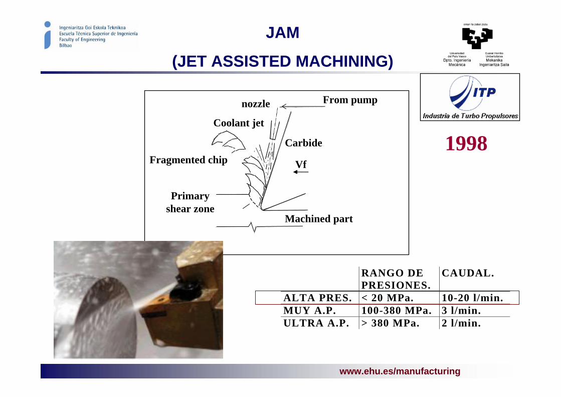
JAM
(JET ASSISTED MACHINING)
RANGO DEPRESIONES.
CAUDAL.
ALTA PRES. < 20 MPa. 10-20 l/min.MUY A.P. 100-380 MPa. 3 l/min.ULTRA A.P. > 380 MPa. 2 l/min.
From pumpnozzle
Vf
Coolant jet
Primaryshear zone
Machined part
Carbide
Fragmented chip1998

www.ehu.es/manufacturing
High pressureequipment• Pressure 350 bares.
• Flow 40 l/min.
Vertical lathe
• n 300 rpm.
• Power70 Kw.
• ∅ plate 1.800 mm.
Roughing
• Vc 120-140 m/min.
• ap 2-3 mm.
• f 0.3 mm/rev.
• t 10 min.
Finishing
• Vc 180 m/min.
• ap 0.5 mm.
• f 0.2 mm/rev.
• t 12 min.
Superfinishing
• Vc 200-250 m/min.
• ap 0.2 mm.
• f 0.15 mm/rev.
• t 10 min.
JAM
(JET ASSISTED MACHINING)

www.ehu.es/manufacturing
INCONEL 718
Vc (m·min-1) 150, 200, 250, 350, 500, 900
f (mm·rev-1) 0.1, 0.2, 0.3, 0.4
ap (mm) 0.2, 0.35, 0.5, 2
(Vbmax) 0.4
RAMPING
apCapa
endurecida
Tool: ceramics, carbide and PCBN
Cutting conditions and
Cutting strategies

www.ehu.es/manufacturing
INCONEL 718 MACHINING
EDAXEDAX
Ni, Cr, FeComponen-tes Inconel
718
Q
QRED CUTTING OF INCONEL 718 ADIABATIC
CONDITIONS
Ceramics tools (alumnina with whiskers of CSi)

www.ehu.es/manufacturing
PLASMA ASSISTED MACHINING
Millingcenter
Plasma welding
equipment

www.ehu.es/manufacturing
“HIGH PERFORMANCE MACHINING OF SUBCRITICAL THICKNESS PARTS”
±0,2Tolini1,6eini31,53Qini540´HH±0,25Tolini2eini21,02QiniCeramic
±0,2Tolini1,6eini2,28Qini150´HH±0,25Tolini2eini1,52QinicarbideStub vanes
±0,15Tolini1,04eini201,6Qini19,6´HH±0,2Tolini1,3eini134,4QiniCeramic
±0,15Tolini0,32eini18,9Qini10´HH±0,2Tolini0,4eini12,6QinicarbideBride
±0,05Tolini2Faspecto3,675Qini301´HH±0,05Tolini2Faspecto2,45Qinislots
±0,15Tolpos±0,018Tol Diam12,276Qini6´HH±0,15Tolpos±0,018Tol Diam8,184QiniPINS
±0,25Tolpos±0,075Tol Diam12,276Qini26´HH±0,25Tolpos±0,075Tol Diam8,184Qiniholes
±0,15Tolini1,04eini201,6Qini81´HH±0,2Tolini1,3eini134,4QiniCeramic
±0,1Tolini0,32eini18,9Qini53´HH±0,2Tolini0,4eini12,6QinicarbideTurning walls
0,8658Qini6´HH0,577QiniScallops
FeaturesObjetive OPENAERState of the art
PROYECTO OPENAER

www.ehu.es/manufacturing
STRUCTURAL COMPONENTS
High speed milling of- Aluminium alloys
- Composites CFRP

www.ehu.es/manufacturing
MONOLITHIC STRUCTURES
Diseño Airbus Diseño Boeing
MACHINING

www.ehu.es/manufacturing
COMPOSITES IN AIRFRAMES
• 1. Radome: Specialized glass Prepregs. Flexcore®honeycomb
• 2. Landing Gear Doors and Leg Fairings: Glass/carbon Prepregs,honeycomb
• 3. Galley, Wardrobes, Toilets: Fabricated Fibrelampanels
• 4. Partitions: Fibrelam panel materials• 5. Wing to Body Fairing: Carbon/glass/aramid
Prepregs. Honeycombs.• 6. Wing Assembly: (Trailing Edge Shroud Box)
Carbon/glass Prepregs. Nomex® honeycomb.• 7. Flying Control Surfaces : Glass/carbon/aramid
Prepregs. Honeycomb.• 8. Passenger Flooring: Fibrelam panels• 9. Engine Nacelles and Thrust Reversers:
Carbon/glass Prepregs. Nomex® honeycomb.• 10. Pylon Fairings: Carbon/glass Prepregs.• 11. Winglets: Carbon/glass Prepregs• 12. Keel Beam: Carbon Prepregs• 13. Cargo Flooring: Fibrelam panels• 14. Flaptrack Fairings: Carbon/glass Prepregs.• 15. Overhead Storage Bins: Prepregs/fabricated
Fibrelam panels• 16. Ceiling and Side Wall Panels: Glass Prepregs• 17. Airstairs: Fabricated Fibrelam panels
18. Pressure Bulkhead: Carbon Prepregs
19. Vertical Stabilizer: Carbon/glass/aramid Prepregs
20. Rudder: Carbon/glass Prepregs. Honeycomb bonded assembly
21. Horizontal Stabilizer: Carbon/glass Prepregs
22. Elevator: Carbon/glass Prepregs. Honeycomb bonded assembly
23. Tail Cone: Carbon/glass Prepregs

www.ehu.es/manufacturing
MILLING OF CFRP
Trimming of large CFRP Drilling with FATRONIK for MTorres
Problems: Dust , tool wear, vibration, composite damage
Solutions:Tool optimisation:
Carbide gradeCoating (new nanoCo)Cutting conditions
Working with: Kendu, Platit, DyFA, Fatronik

www.ehu.es/manufacturing
STABILITY OF MACHINING

www.ehu.es/manufacturing

www.ehu.es/manufacturing
AEROEBAKI
PRAXIS
Entorno/Colaboraciones
IndustrialIndustrial
IndustrialIndustrial
IndustrialIndustrial
CientíficaCientífica
CientíficaCientífica
AEROSFIN
SKY-SKINCientíficaCientífica
STABILITY OF MACHINING

www.ehu.es/manufacturing
Thin walls
Global ‘stability lobes diagram’, taking into account the relative displacement between tool and part.
Theoretical Solution: Calculation of the Stability Lobes
Introduction
0º180º
90º
Difference of phaseDifference of phase
Step 1
Step 3
Step 2
Step 4

www.ehu.es/manufacturing

www.ehu.es/manufacturingExperimental Validation
CHATTER
CHATTER
STABLE
FORCED VIBRATION

www.ehu.es/manufacturing

www.ehu.es/manufacturing
OPTIMIZATION OF ROUGHING
Useful for users and machine manufacturers (redesing)

www.ehu.es/manufacturing
MQL- DRY MACHINING

www.ehu.es/manufacturing
Output fluid speed 6,4m/s.Simulation MQl, Output flow speed 125m/s.
Sistema MQL Sistema convencional
0.04 ml/min
MQL- DRY MACHINING
Ecological aspects
Technological aspects
Economical aspects
Ecoefficiency
Ecolonomía
Sectors:
Automotive (15% cost)Aeronautics

www.ehu.es/manufacturing
MQL(MINIMAL QUANTITY
OF LUBRICANT)
OPTIMIZACIÓN:
Obtención de la introdución optima del fluido en la zona de corte.
Reducción del caudal a valores inferiores a 0,06ml/min, obteniendo desgastes inferiores que con fluidos de corte convecionales.
Type of coolant
VB a 45m VB a 158m
MQL a 0,06ml/min 0,042 0,120
MQL a 0,04 ml/min 0,047 0,142
Emulsion 0,071 0,161
aireaceite
<2µm

www.ehu.es/manufacturing
TRIBOLOGY ASPECTS
Is the maximum temperature in the rake face 300º???? BUL In collaboration with:

www.ehu.es/manufacturing
DRILLING OF AUSTENITIC STAINLESS STEELS
0
0,02
0,04
0,06
0,08
0,1
tiempo de mecanizado
des
gas
te d
e fl
anco
Vb
b
(mm
)
304-k 316-k 303-k 316-S
AISI 303,304, and 316
Conditions near-to-dry
High pressure coaxial
Redesing of drilling tools

www.ehu.es/manufacturing
MACHINING OF ADI CASTINGS
Project Manunet ADI-TAPS
WZL Aachen, Huvershorn, UHS, ME Platit, our group
Drilling, Threading, Milling
Typical machinability project:(German type)
Tools (substrate, geometry, coating)
ConditionsSurface integrity

www.ehu.es/manufacturing
FIVE-AXIS MILLING
Working with five axes in continuous interpolation

www.ehu.es/manufacturing
MACHINING
MODELLING

www.ehu.es/manufacturing
2D and 3D SIMULATION WITH FEM
Cutting Speed ( Vc)Feed ( f)
Depth of cut ( doc)Length of cut
Cooling
Now using Thirdwave Advantedge
-As tool for hypothesis and results analysis
- Model developed in Abaqus ExplicitTogether with Tekniker
www.ehu.es/manufacturing
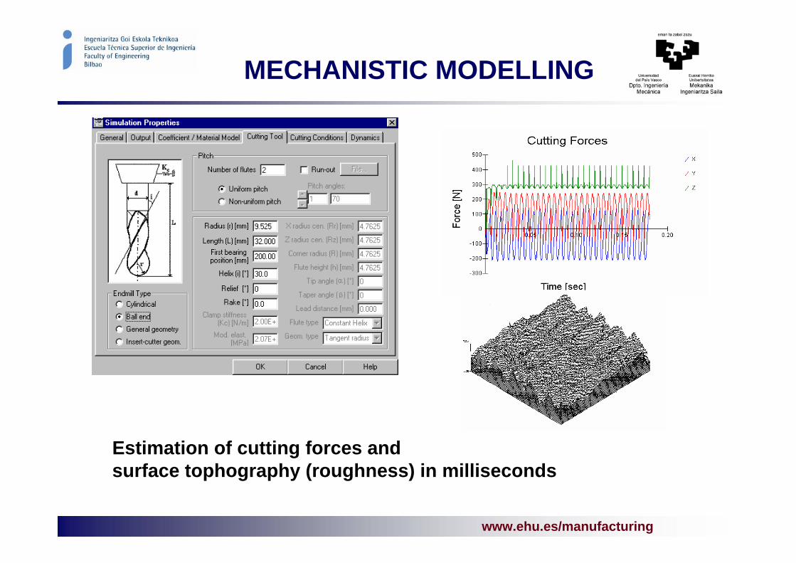
MECHANISTIC MODELLING
Estimation of cutting forces and surface tophography (roughness) in milliseconds

www.ehu.es/manufacturing
( ) ( )( ) ( )( ) ( )⎪
⎩
⎪⎨
⎧
⋅+=⋅+=⋅+=
db,,tKdSKz,dFdb,,tKdSKz,dF
db,,tKdSKz,dF
nacaea
nrcrer
ntctet
κθΨθκθΨθκθΨθCOEFFICETS TYPESCOEFFICETS TYPES
1. Mean coefficents2.2. BilinearBilinear models3. Ortoghonal to oblicue4. Etc.
MECHANISTIC MODELMECHANISTIC MODEL
• Using empirical laws with specific coefficients
• Coeffiencits for each couple: materailand tool
• Process with high complexitity• In miliseconds, the cutting forces.
λVc
µ
Discreteelement of the
edge
MODEL DEVELOPED
Antecedentes
www.ehu.es/manufacturing
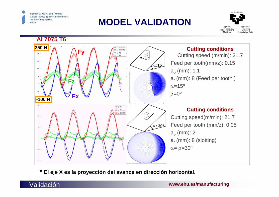
α:15º
Fy
Fz
Fx
α: 30º
Validación
Cutting Cutting conditionsconditions
Cutting speed(m/min): 21.7Feed per tooth (mm/z): 0.05ap (mm): 2ar (mm): 8 (slotting)α= ρ=30º
Cutting Cutting conditionsconditionsCutting speed (m/min): 21.7
Feed per tooth(mm/z): 0.15ap (mm): 1.1ar (mm): 8 (Feed per tooth )α=15ºρ=0º
250 N
-100 N
* El eje X es la proyección del avance en dirección horizontal.
MODEL VALIDATION
Al 7075 T6

www.ehu.es/manufacturing
Material:Aluminio 7075-LMaterial de Hta:Metal duro+TiAlNΦ =6 Z=2
Condiciones de corte:Velocidad de corte(r.p.m.): 3000Avance por filo(mm/z): 0.07ap(mm): 1ae(mm): 4
1 revolución
OUR GOAL: FLEXIBLE TOOL
RunRun out out withoutwithout cuttingcuttingDisplacementDisplacement in cuttingin cutting
But the system is flexible:
-Slender tools
-Thin walls
Colaborando con

www.ehu.es/manufacturing
INTEGRATION OF MODELS IN CAM
Cutting Parameter Calculator
Vc, fz, ap, ae
Roughing Toolpath
SemifinishingToolpath
Finishing Toolpath
•Z-level Contouring• Special Strategies
Virtual Machining Simulation
• Collision Detection
Part Design
NEW CAMSCHEME
Validated NC Code
Postprocessing
Cutting Force Calculator
HSM Knowledge
Multimedia support
Use of historicalbackground
CAM
SOFT Roughness
estimation
www.ehu.es/manufacturing
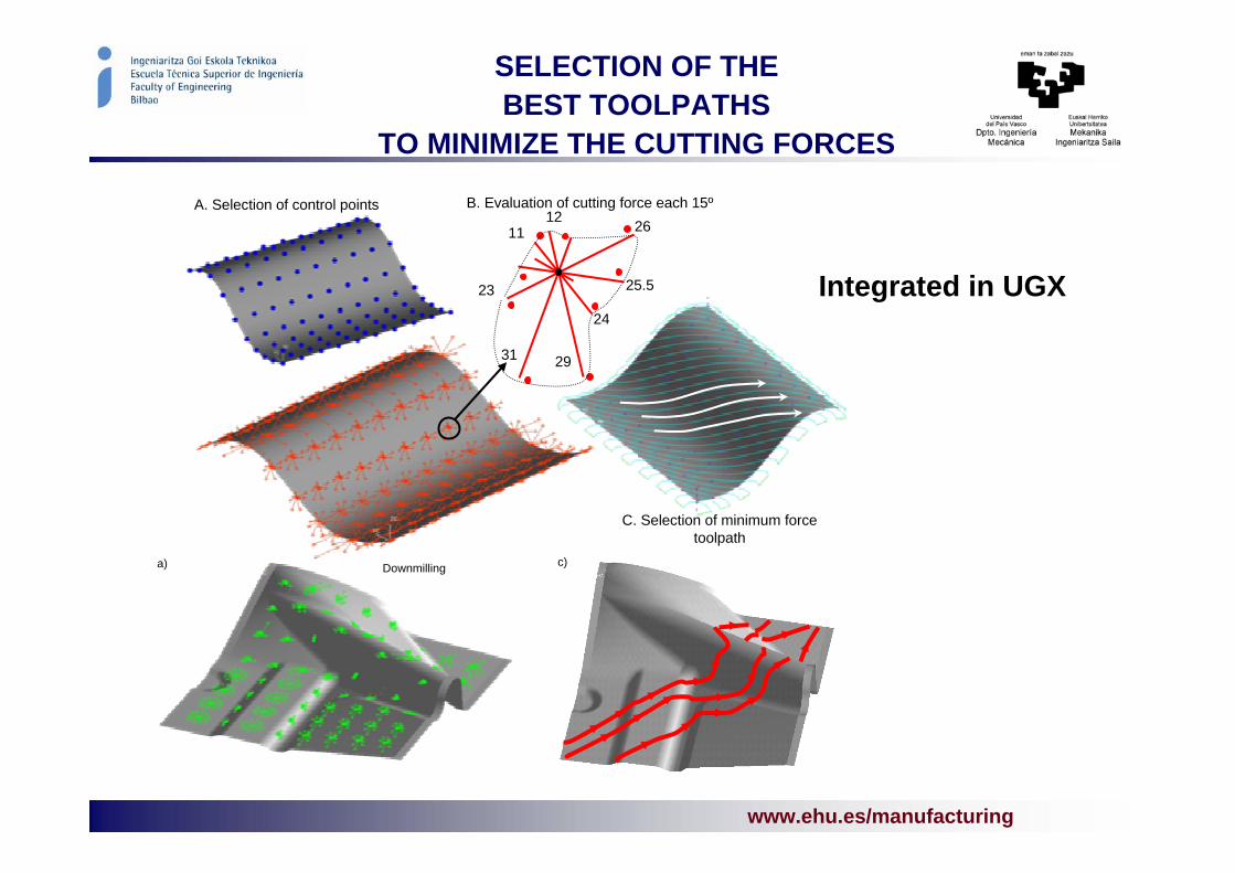
SELECTION OF THE BEST TOOLPATHS
TO MINIMIZE THE CUTTING FORCES
Downmillinga) c)
A. Selection of control points B. Evaluation of cutting force each 15º
C. Selection of minimum forcetoolpath
29
12
23
31
24
2611
25.5 Integrated in UGX

www.ehu.es/manufacturing

www.ehu.es/manufacturing
Hybrid (Low computational)
way
SPECIFIC COEFFICIENTS EXTRATED FROM FEM
MillingMillingexperimentsexperiments
Virtual test: orthogonal cutting
Virtual tests: oblique cutting
ResultingResulting the the K’sK’s
Mechanistic model
Ortho to oblique:Armarego theoryGeometric projections
dSKdbtKdF tentct +=dSKdbtKdF renrcr +=
dSKdbtKdF aenaca +=
Direct (High computational)
way
Advantages:
Dependency on i y de Vc
Dependency of the rake angle
Elimination of experiments
ABAQUS
Advantages:
Dependency on i y de Vc
Dependency of the rake angle
Elimination of experiments

www.ehu.es/manufacturing
BURNISHING

www.ehu.es/manufacturing
BALL BURNISHING
Technique for a better surface finishingTwo main effects:
- Reduction of the roughness
moulds and dies
- Surface hardening
aeronautic parts
P:20 MPa
==
N: 500 N
28º
dxxyl
R ml
ma ∫=
0)(1

www.ehu.es/manufacturing
BALL BURNISHING
Inconel 718 (AMS 5596, 52Ni-19Fe-18Cr-5(Cb+Ta)-3Mo-0.9Ti-0.5Al) Driver: Surface integrity - Residual stresses
www.ehu.es/manufacturing
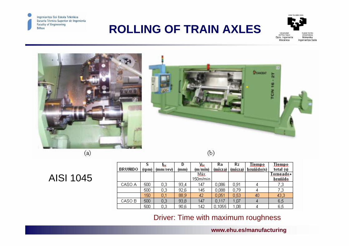
ROLLING OF TRAIN AXLES
AISI 1045
Driver: Time with maximum roughness
www.ehu.es/manufacturing
BALL BURNISHING OF DIES AND MOULDS
Diriver: reduction of manual polishing
pulido_ICM-ICT.avi

www.ehu.es/manufacturing
ULTRASONIC ASSISTED TURNING
Effect of ultrasonic vibration:
-Roughness reduction- isotropic-Tool wear
Parameters:
-Direction of vibration-Amplitude
Other processes
-Dressing of girnding wheels-Drilling -Wire calibration

www.ehu.es/manufacturing
KINEMATIC ERRORS IN FIVE-AXIS MILLING CENTRES
Error at the Tool tip
- Gantry with two-rotary head
- Three axes with two-axis bed
- On axis in tool and other in bed
Two objetives:
Estimation by Homogenous matrix
Test part and procedures for testing

www.ehu.es/manufacturing
UPDATING OF FEM MODELS BY MODAL ANALYSIS
FEM4 → 54,85 HzEMA3 → 58,91 Hz
MAC = 94,5 %

www.ehu.es/manufacturing
ELECTRODISCHARGE MACHINING

www.ehu.es/manufacturingwww.ehu.es/manufacturing
Wire Electrical Discharge Machining (WEDM)
From basic knowledge…
• Modeling of wire deformation• Influence on precision of WEDM’ed parts
… to competitive advantage
• Increase of machine precision• Development of new industrial products
Avance del hilo
EDM MACHINES AND PROCESSESEDM MACHINES AND PROCESSES

www.ehu.es/manufacturingwww.ehu.es/manufacturing
WIRE ELECTRICAL DISCHARGE MACHINING (WEDM)
Gear pump oval
Ø3mm
EDM MACHINES AND PROCESSESEDM MACHINES AND PROCESSES
Precision in corner-cutting

www.ehu.es/manufacturingwww.ehu.es/manufacturing
WIRE ELECTRICAL DISCHARGE MACHINING (WEDM)
Precision in taper-cutting: Modeling of wire deformation
- FE Models of wire, including non-linearities:
- Mechanics of contact wire-guide- Plastic behaviour of ‘soft’ wires- Large-deformations- Stress stiffening
- Design of Experiments Models including theinfluence of forces exerted during the EDM process
EDM MACHINES AND PROCESSESEDM MACHINES AND PROCESSES

www.ehu.es/manufacturingwww.ehu.es/manufacturing
NUMERICAL MODELS OF THE EDM PROCESS
Simulation of material removal rate and surface finish
EDM MACHINES AND PROCESSESEDM MACHINES AND PROCESSES
tT
kq
zT
yT
xT G
∂∂⋅=+
∂∂
+∂∂
+∂∂
α1
2
2
2
2
2
2
186.28 µm
1.9901 mm
2.0591 mm
Alpha = 243° Beta = 35°
100
80
60
40
20
0
ij
k

www.ehu.es/manufacturingwww.ehu.es/manufacturing
Application of knowledge to the development of NEW INDUSTRIAL PRODUCTS
• Precision WEDM cutting of LARGE-THICKNESS parts (up to 600mm)International Patent and Ph.D. Thesis
• Technologies of HIGH-SPEED CUTTING in new generation machines
• Precision dies for bar drawing in ADVANCED CERAMIC MATERIALSIndustrial partnership (4 companies)
• Real-time EDM PROCESS MONITORING
Ceramic drawing diein B4C
WEDM’ed Test-part in tool steel (Sverker21). Precision: 9µm per
side, thickness 400mm
Instrumentation andsoftware for WEDM process monitoring
EDM MACHINES AND PROCESSESEDM MACHINES AND PROCESSES

www.ehu.es/manufacturing
GRINDING

www.ehu.es/manufacturingwww.ehu.es/manufacturing
Fundamentals of the grinding process: numerical models of thethermal behaviour of the process
• PREDICTION OF THERMAL DAMAGE in ground parts
• Numerical model: ‘at-home’ developed SOFTWARE
• Inclusion of MECHANIS OF CONTACT
• MODEL OPTIMIZATION
• Industrial VALIDATION
Equipment for temperature measurementin industrial grinding operations
GRINDING MACHINES GRINDING MACHINES AND PROCESSESAND PROCESSES

www.ehu.es/manufacturingwww.ehu.es/manufacturing
Tribology of Grinding: EXPERIMENTAL MODELS OF FORCES AND WEAR.
• Measurement of FORCES y FRICTION COEFFICIENT during the process
• Characterisation of wheel surface: EVOLUTION OF WEAR
• EMPIRICAL MODEL OF FORCES as a function of wheel wear
Normal and tangential forces, andfriction coefficient as a function of
wheel wear
µm
0246810121416182022242628303234
34.56 µm
3.0015 mm
2.085 mm
Alpha = 26° Beta = 27°
Fn
Ft
Fn
Ft
Grit wear
Active surface of the wheel
GRINDING MACHINES GRINDING MACHINES AND PROCESSESAND PROCESSES

www.ehu.es/manufacturingwww.ehu.es/manufacturing
Development of new industrial products: ELECTRICAL DISCHARGE DRESSING of superabrasive wheels.
• EXPERIMENTAL STUDY and PROCESS INDUSTRIALISATION
dielectric
Removal of worn grits and loadedmaterial from the active surface of
the wheel using the EDM effect
GRINDING MACHINES GRINDING MACHINES AND PROCESSESAND PROCESSES

www.ehu.es/manufacturing
LASER
Working with Diode laser (marGUNE)
And CO2 laser (Robotiker)

www.ehu.es/manufacturingLaser - Plasma www.ehu.es/manufacturing
ADVANCED HIGH STRENGTH STEELS (AHSS) LASER CUTTING
• BACKGROUND: new materials involves process parameters changes.
• OBJECTIVE: Optimize laser cutting process parameters for three different AHSS: DP750, TRIP GXE 450B and DIN EN 10292 (with Zn coating).
• HYPOTESIS: If the cutting parameters maximize the cutting speed, improve the quality of the cuts and minimize the HAZone: Cutting AHSS for body car parts.
• EXPERIMENTAL: Tests on different AHSS with a 2.5 kW CO2 laser. Measurements of the kerf and metallurgical analysis
• RESULTS: Optimum parameters and parameter windows for each material.

www.ehu.es/manufacturing
LASER & PLASMAMATERIAL DEPOSITION
• BACKGROUND: High added value parts repairs are highly demanded by tooling and aeronautical parts industries.
• OBJECTIVE: High quality repayments on complex parts using selective metal deposition.
• HYPOTESIS: If the particle flow can be simulated in a laser cladding nozzle, the set of laser parameters can be fitted for a specific nozzle design or a new optimum nozzle design can be calculated.
• EXPERIMENTAL: Tests on DIN 1.2379 tool steel up to 62 HRC. Tests with – plasma and wire feeding techniques (very
economic), – Laser & wire feeding, – laser & powder feeding.
CFD Numerical simulation for nozzle design
Laser - Plasma

www.ehu.es/manufacturing
LASER POLISHING
• BACKGROUND: Surface polishing is a highly manual technique. Very expensive and time consuming. Die & Mould industry demands automatic polishing techniques. On the other hand, Rapid Manufacturing Techniques produce low surface quality parts.
• OBJECTIVE: Improve surface finishing of metallic complex surfaces by using a laser source.
• HYPOTESIS: If laser polishing process is reliable and automatic, a laser sintered part can be polished in the same SLS machine in one step, resulting a fully functional and finished part.
• EXPERIMENTAL: Tests on SLS Laserform ST-100 and DIN 1.2344 up to 52 HRC.
• RESULTS: Up to 85% surface roughness reduction.
Stainless steel
Infiltred Bronze
PorosityTest SLS-x50
304 HV (≈30HRC)
142 HV
174 HV
Laser - Plasma

www.ehu.es/manufacturing
THANKS FOR YOUR ATTENTION!!