group number hyunari 13-ee-001 i newthlnklng. …
TRANSCRIPT

GROUP
ENGINE
NUMBER
13-EE-001
HyunaRI I nEWTHlnKlnG. ELECTRICAL nEW POSSIBILITIES. f----------+----------j
MODEL(S) Technical Service Bulletin DATE JANUARY 2013 Sonata (NF/YF)
Santa Fe (CM/AN)
SUBJECT: STARTER MOTOR LEVER REPLACEMENT NOTE: This bulletin is revised to add 2012-2013MY. A bench test has been added to the Initial Starter Inspection procedure to confirm the starter incident condition. Be sure to install the lever stop as described in step-14. A review of warranty return parts show the lever stop missing on some incident starters replaced subsequent to this repair attempt.
Description: • This bulletin provides the repair procedure for replacing the starter motor lever in some
2009-2013MY 2.4L Sonata , and 2010-2013MY 2.4L Santa Fe. • The symptom for this incident is a No Start condition. • The starter motor spins, but the starter does not crank the engine. • When the starter is bench tested, the pinion gear does not travel out or retract fully. • When this condition is confirmed , starter lever should be replaced per procedure of this bulletin .
NOTE: Starters replaced as an assembly will be subject to WTC Part Return Request. Claim adjustment may occur if a broken lever is present but the repair procedure was not properly followed . If during disassembly for this bulletin, a condition is confirmed requiring the starter assembly to be replaced (other than the lever) , reassemble the starter completely (hand tight screws are OK). Describe clearly on the Repair Order why the starter had to be replaced.
Broken lever found at disassembly:
Applicable Vehicles: • 2010-2013MY SANTA FE (CM/AN) 2.4L • 2009 -2013MY SONATA (NF/YF) 2.4L
Parts Information:
Warranty Information:
Model Op Code Operation Op Time Causal Part# Nature Code Cause Code
YF/NF, 36131FOO
Starter Lever 0.8 36100-2G100 N59 C06
CM/AN Replacement
Circulate To: General Manager, Service Manager, Parts Manager, Warranty Manager, Service Advisors , Technicians, Body Shop Manager, Fleet Repair

SUBJECT: ST ARTER MOTOR LEVER REPLACEMENT
Tools Required:
• Torque Wrench • ?mm and 13mm Sockets • TORX T20 Screwdriver • Permanent Marker Pen (to make alignment marks on the starter parts) • Remote Starter Switch
Initial Starter Inspection:
i. Starter Removal :
(1) Note customer radio presets so as to program them back later. (2) Disconnect the battery negative cable . (3) Disconnect the starter cable (A) from the B-terminal (B) on the solenoid (C). (4) Disconnect the connector (D) from the S-terminal (E) . (5) Remove the 2 bolts holding the starter, and then remove the starter. D
ii . Perform Diagnostic Bench Test:
Follow~ the below Warnings and Notes:
B WARNING
• During this operation the starter will activate, and the body of the starter must be secured from moving (ex: placing in a vise).
• Keep hands/fingers/ loose clothing away from the pinion or personal injury may result.
• To avoid electrical shock, first connect booster cables between the 12V battery and the solenoid 8-terminal (high current), without touching the solenoid S-terminal.
• The starter is then safely activated by contacting 12V to the solenoid $
terminal (low current) such as by a remote starter switch tool.
TSB #: 13-EE-001 Page 2 of 11

SUBJECT: STARTER MOTOR LEVER REPLACEMENT
*NOTE
• Do not activate contactor (A) more than 5 seconds to avoid damage of the starter coil. • When contactor (A) is activated , the pinion must extend and the starter must rotate .
Perform this functional test per the illustrated setup below.
• Confirm that the motor spins OK.
• Confirm pinion gear operation :
o If pinion gear fails to move out or retract fully, then perform the remainder of this bulletin to repair a broken lever.
Rear view
)
(+)
*NOTE
S-Terminal
12V Battery or Booster Box
(-)
• This bulletin does not apply if the starter spins too slow or does not spin at all. • In this case perform normal warranty repair for a starter replacement.
TSB #: 13-EE-001 Page 3 of 11

SUBJECT: ST ARTER MOTOR LEVER REPLACEMENT
Starter Disassembly and Inspection:
1. Apply 2 pairs of alignment marks from front bracket (A) to solenoid (8) , and front bracket (A) to the yoke assembly (C) as shown .
2.
3.
*NOTE
Alignment marks are necessary to assure proper function of the starter after reassembly.
Using a 13mm socket, remove each of the following :
• Starter solenoid M terminal nut (E) • Terminal wire (D).
Using a TORX T20 screwdriver, remove the following:
• 2 solenoid screws (C). NOTE: Discard these 2 screws which will be replaced by new screws from the kit.
• Solenoid assembly (D) from starter.
*NOTE
• Do not clean grease from the spring/plunger.
• If the solenoid is dropped/damaged it cannot be reused. Replace the solenoid with part 36120-28110.
4. Using a ?mm socket, remove the through bolts (F) that are holding the yoke assembly to the front bracket.
TSB # : 13-EE-001
c
B
E
Page 4 of 11

SUBJECT: STARTER MOTOR LEVER REPLACEMENT
5. Slightly pull out the yoke assembly (C) from the front bracket (A) to apply a new alignment mark between front bracket (A) , reducer assembly (B) and yoke (C) .
6 . Remove the yoke assembly (C) with the armature and end cap contents intact as an assembly.
*NOTE
Do not remove components from the yoke assembly (C)
7. Remove lever stop (D) from the front bracket.
8. • Remove reducer assembly (E) from front bracket (A) .
• Remove broken lever (C) from ORC (D).
(ORC= Over Running Clutch)
TSB #: 13-EE-001
c
D E
Page 5 of 11

SUBJECT: STARTER MOTOR LEVER REPLACEMENT
*NOTE -
Component Inspection:
• ORC must rotate in one direction and lock in the opposite direction without any rough spots.
• If the ORC is found to be faulty stop this procedure and perform normal warranty repair for a starter replacement.
9. Remove the lever (A) from plunger by pointing lever up and removing from pins (8).
Lever Replacement:
10. Install the replacement lever (A) by aligning slots with pins and moving lever at a right angle (90 degrees) from to the plunger (B) as shown .
*NOTE
After assembly, do not remove the lever from the 90 degrees position.
TSB #: 13-EE-001
B
Page 6 of 11
SUBJECT: STARTER MOTOR LEVER REPLACEMENT
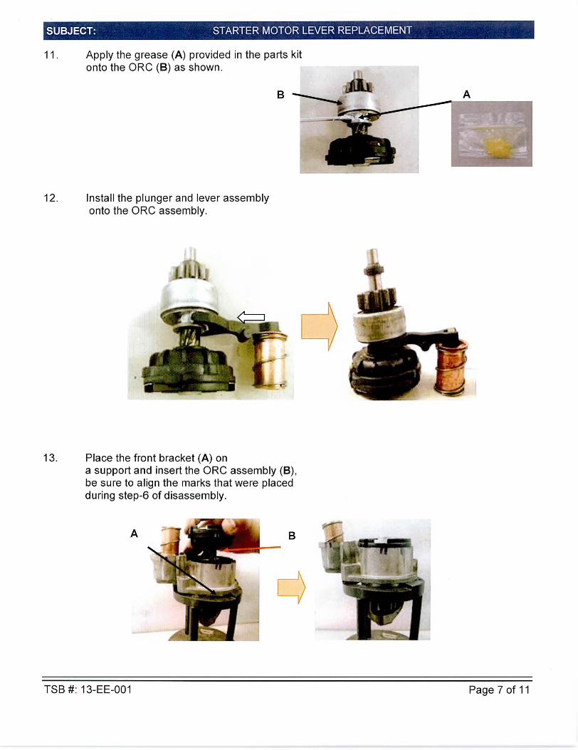
11 . Apply the grease (A) provided in the parts kit onto the ORC (B) as shown.
12. Install the plunger and lever assembly onto the ORC assembly.
13. Place the front bracket (A) on
B
a support and insert the ORC assembly (B) , be sure to align the marks that were placed during step-6 of disassembly.
A B
TSB #: 13-EE-001 Page 7 of 11

SUBJECT: STARTER MOTOR LEVER REPLACEMENT
*NOTE
• Confirm correct alignment marks between the front bracket and ORC. • Correct assembly check: There should be no gaps between stopper (C) and front
bracket (A) .
14. Install lever stop (D)
*NOTE
The lever stop (F1) should be flush with the front bracket (F2).
15. Using a 7mm socket and torque wrench install 2 through bolts (A) and (B) into yoke assembly and bracket.
Tightening sequence: 1: Bolt (A) (torque = 8 to 9 Nm) 2: Bolt (B) (torque = 8 to 9 Nm) 3: Confirm bolt (A) torque (8 to 9 Nm)
TSB #: 13-EE-001 Page 8 of 11

SUBJECT: STARTER MOTOR LEVER REPLACEMENT
16.
*NOTE
Inspection for Correct Reassembly: • Ensure the lever stop (C) remains in the position shown. • Ensure that the plunger spring (D) is still in place.
• Be sure to assemble the yoke assembly to the front bracket according to the marks placed during disassembl1' of Step-1 .
• Verify that the 2 long bolts are in contact with the yoke assembly. If not, disassemble and restart the installation o eration .
• Check that the yoke assembly (E) is in contact with front bracket (F) . If not, go back to Step-15 and check for proper alignment of reducer gear to the front bracket.
• Install solenoid (A) onto the starter assembly (B) ensuring that the plunger spring is still in place.
• Using a TORX T20 screwdriver Install 2 new solenoid screws (C) and (D) from the kit into solenoid and front bracket.
Tightening sequence: 1: Solenoid screw (C) (torque= 3.0-4.2Nm) 2: Solenoid screw (D) (torque= 3.0-4.2Nm) 3: Confirm screw (C) torque (3.0-4.2 Nm)
A
TSB #: 13-EE-001 Page 9 of 11

SUBJECT: ST ARTER MOTOR LEVER REPLACEMENT
*NOTE
Inspection for Correct Reassembly: • Be sure to assemble the solenoid according to the marks placed during
disassembly in Step-1. • Check that the 2 screws (C) and D are in contact with front bracket (E) .
• Check that solenoid (A) is in contact with front bracket (E) . If not, disassemble and restart the installation operation (Step-18).
• Install M wire (A) onto solenoid M terminal (8) . Using a 13mm socket and torque wrench , tighten M terminal nut (C) to 7.8-11 .8 Nm.
c
• After applying torque , ensure that the nut (C) is in contact with the braid. ,-,
c
TSB #: 13-EE-001 Page 10 of 11

SUBJECT: STARTER MOTOR LEVER REPLACEMENT
Starter Functional Test after reassembly:
17. Perform starter bench test.
Refer to procedure detailed on page 3 and re-test starter to confirm successful repair. If any abnormal noise is detected , recheck the steps of the assembly procedure to ensure proper assembly.
Starter Installation:
18. Install starter in reverse order of removal.
19. Connect negative battery cable.
20. Reprogram the customer radio presets.
TSB #: 13-EE-001 Page 11 of 11