group of spanish electricity companies for studies … · group of spanish electricity companies...
TRANSCRIPT

GROUP OF SPANISH ELECTRICITY COMPANIES FOR STUDIES ON IEC 61850
MINIMUM COMMON SPECIFICATION FOR SUBSTATION PROTECTION AND CONTROL EQUIPMENT IN ACCORDANCE WITH THE IEC 61850
STANDARD
EDITION MODIFICATION DATE
3 Establishment of the final document 09.06.10

REFERENCE: E3/0001
EDITION: 3 (09.06.10)
SUPERSEDES EDITION: 2 (06.05.10)
PAGE 2 OF 182
GROUP OF SPANISH ELECTRICITY COMPANIES ON IEC 61850
MINIMUM COMMON SPECIFICATION FOR SAS EQUIPMENT
IN ACCORDANCE WITH THE IEC 61850 STANDARD
EXECUTIVE SUMMARY The “E3 - Spanish Electricity Companies for Studies on IEC 61850” is a working group formed by repre-
sentatives and specialists from the main Spanish electricity companies, who have agreed on the urgent
necessity to come to a set of unified criteria about minimal requirements to comply with by the devices
to be installed in their substations under the IEC 61850 standard.
This is a result of the common standpoint reached by all participants after the experience gathered
through several pilot projects.
The E3 group feeling is that the future success of IEC 61850 will be based not only on filling, under
common criteria, the gaps that are still contained within the standard, but also on driving the manufac-
turer’s developments according to the user’s needs.
It is within the hope of this executive summary to clearly identify the requirements that have been
agreed as a conclusion of the studies and discussions developed through the document hereinafter.
It is assumed that some of the requisites hereby stated are more restrictive than IEC 61850 require-
ments, but it has been agreed that, from the user point of view, this is the best way to actually make
technical benefit of IEC 61850 adoption within companies.
General Approach
The structure of the present document reflects the methodology that has been used along multiple stu-
dies and research activities performed by the companies participating in the E3 group.
a) Chapter 3 defines the representative Spanish substation topologies and busbar configurations
that impose the highest level requirements. Three (3) case studies have been chosen finally:
Type 1 case study. Double busbar arrangement on the two main voltage levels.
Type 2 case study. One-and-a-half breaker on the higher voltage level and double bus-
bar on the lower voltage level.
Type 3 case study. Topology commonly known as ‘H’.
b) Chapter 4 specifies the requisites that SAS (Substation Automation System) systems should
comply with in terms of operational functionality.
c) From chapter 5 onwards, a set of common characteristics is developed, in terms of SAS mini-
mum requisites. All companies have agreed to jointly demand them within their tenders and
specifications, in order to meet their respective engineering, operation and maintenance needs.

REFERENCE: E3/0001
EDITION: 3 (09.06.10)
SUPERSEDES EDITION: 2 (06.05.10)
PAGE 3 OF 182
GROUP OF SPANISH ELECTRICITY COMPANIES ON IEC 61850
MINIMUM COMMON SPECIFICATION FOR SAS EQUIPMENT
IN ACCORDANCE WITH THE IEC 61850 STANDARD
Highlighted requisites
SAS LAN Topology Multi-ring collar topology: RSTP (Rapid Spanning Tree Proto-col) protocol for Substations Type 1 and 3 is proposed.
Redundant double-star topology: PRP (Parallel Redundancy Protocol) protocol for Substations Type 2 (as it is expected to be defined in the next IEC 61850 standard edition) is pro-posed.
The HSR protocol will be assessed in the future.
The Ethernet switch is considered as another IEC 61850 IED.
IED Configuration Only one, and no more than one, CID file must contain ALL information to configure the IED, and no additional or sup-plementary configuration files will be allowed.
IEDs have to be able to be configured directly from a CID file
by means of the CID file uploading process, and all of the
three following methods must be available:
- ACSI services
- FTP protocol
- USB local upload
Standard naming rules and common ways to receive, store,
load and validate the CID file are provided.
‘Inref’ data objects for LN binding shall be used when applica-ble.
A fully IEC-61850-consistent modeling specification for pro-grammable logic configuration is provided.
A fully IEC-61850-consistent modeling specification for hu-man-machine interfaces (HMI) is provided.
All other functions (e.g. protection) should be modeled so that the user can also configure them by IEC 61850 methods.
Private configuration parts in the CID are initially allowed,

REFERENCE: E3/0001
EDITION: 3 (09.06.10)
SUPERSEDES EDITION: 2 (06.05.10)
PAGE 4 OF 182
GROUP OF SPANISH ELECTRICITY COMPANIES ON IEC 61850
MINIMUM COMMON SPECIFICATION FOR SAS EQUIPMENT
IN ACCORDANCE WITH THE IEC 61850 STANDARD
but should eventually disappear.
Proprietary configuration tools should become unnecessary in the near future.
IED’s IP address shall be static and modifiable only through local interface (i.e. not ACSI configurable).
IED Reporting Disturbance records will be recorded in COMTRADE format.
Sequence of Events (SOE): an internal file is required inside the IED, which will be a readable copy of the sequence of events contained within the LOG service.
The fault report functionality will be based on ad-hoc data
objects and data-sets specifically created. It will generate a
readable text file.
All IED´s reports will be available for downloading through all
the three following methods:
- ACSI services
- FTP protocol
- USB local download
Communications services
At least 8 GOOSE publishing control blocks in every IED. At
least 64 GOOSE messages subscribed by every IED.
Definition of GOOSE data sets shall have data attribute granu-
larity.
Structure of SV data sets shall be fixed and based on UCA’s
IEC 61850-9-2 “Lite Edition”.
Both GOOSE and SV subscription mechanisms shall be fully
configurable in the CID.
A server will be able to provide up to 7 buffered reports and 7
unbuffered reports.
The LOG service shall be mandatory.
Synchronization For the station bus, SNTP or IRIG-B shall be chosen, depend-
ing on particular needs.
The least demanding SV applications can still operate properly
with IRIG-B; others will require IEEE 1588. ‘Client synchroniza-
tion’ is also considered.

REFERENCE: E3/0001
EDITION: 3 (09.06.10)
SUPERSEDES EDITION: 2 (06.05.10)
PAGE 5 OF 182
GROUP OF SPANISH ELECTRICITY COMPANIES ON IEC 61850
MINIMUM COMMON SPECIFICATION FOR SAS EQUIPMENT
IN ACCORDANCE WITH THE IEC 61850 STANDARD
The LTIM and LTMS logical nodes shall be used for synchroni-
zation configuration and supervision.
Security Analysis based on the IEC 62351 standard.
IEDs must provide authentication for MMS associations, as specified in IEC 61850-7-2. It shall use the Association Control Service Element (ACSE) method.
Association and security events shall be logged. The GSAL logical node shall be used.
Process bus Many independent choices imply broad range of possible architectures. Switched as well as point-to-point process bus are considered.
For the sampled values (SV) transmission, UCA’s IEC 61850-9-2 “Lite Edition” recommendation is loosely followed.
As much as the protocols, the physical connections of the process bus shall comply with international standards. No proprietary solution shall be accepted.
System deployment As a guidance resource, several approaches to the deployment of IEC 61850 in an electric utility are proposed, based on three plant types (outdoor, indoor and mixed).

REFERENCE: E3/0001
EDITION: 3 (09.06.10)
SUPERSEDES EDITION: 2 (06.05.10)
PAGE 6 OF 182
GROUP OF SPANISH ELECTRICITY COMPANIES ON IEC 61850
MINIMUM COMMON SPECIFICATION FOR SAS EQUIPMENT
IN ACCORDANCE WITH THE IEC 61850 STANDARD
INDEX
1. BACKGROUND ............................................................................................................13
2. OBJECTIVES OF THE DOCUMENT ............................................................................15
3. METHODOLOGY ..........................................................................................................16
3.1 Principles...................................................................................................................................................... 16
3.2 Reference documents .................................................................................................................................. 16
3.3 Standard cases ............................................................................................................................................. 18 3.3.1 Type 1: Double Busbar – Double Busbar Topology ................................................................................ 18 3.3.2 Type 2: One-and-a-half Breaker to Double Busbar Topology ................................................................. 19 3.3.3 Type 3: H Topology ................................................................................................................................. 20
3.4 Types of IED ................................................................................................................................................ 21
4. APPLICATIONS (FUNCTIONALITIES AT ELECTRICAL LEVEL) ...............................22
4.1 MV Switchyard ........................................................................................................................................... 23 4.1.1 Criticality I ............................................................................................................................................... 23
4.1.1.1 Remote control ................................................................................................................................ 23 4.1.1.2 Remote access ................................................................................................................................. 23
4.1.2 Criticality II .............................................................................................................................................. 23 4.1.2.1 Permission for sensitive neutral tripping (Ref.MV-2.1) ................................................................. 23 4.1.2.2 Trip of the capacitor bank breaker due to voltage MCB trip (Ref.MV-2.2) ................................... 23 4.1.2.3 Disturbance recording start-up (Ref.MV-2.3) ................................................................................. 24 4.1.2.4 Logical selectivity or MV busbar protection (Ref.MV-2.4) ........................................................... 24
4.1.2.4.1 Delay logic (Ref.MV-2.4.1) ....................................................................................................... 24 4.1.2.4.2 Acceleration logic (Ref.MV-2.4.2) ............................................................................................ 25
4.1.2.5 Line breaker failure (Ref.MV-2.5) .................................................................................................. 25 4.1.2.6 Isolation of a busbar fault or a line fault affected by a breaker failure (Ref.MV-2.6) .................... 26 4.1.2.7 Status signalling from the transformer breaker to the capacitor bank protection IED
(Ref.MV-2.7) ..................................................................................................................................................... 27 4.1.2.8 Status signalling from the longitudinal coupling breaker of busbars 1 to the transformer
protection IEDs (Ref.MV-2.8) ........................................................................................................................... 27 4.1.2.9 Status signalling from the longitudinal coupling breaker of busbars 2 to the transformer
protection IEDs (Ref.MV-2.9) ........................................................................................................................... 27 4.1.2.10 Sending of capacitor bank breaker status change to transformer voltage regulator
(Ref.MV-2.10) ................................................................................................................................................... 27 4.1.3 Criticality III ............................................................................................................................................. 27
4.1.3.1 Permission for earthing of busbars 1 (Ref.MV-3.1)........................................................................ 27 4.1.3.2 Permission for earthing of busbars 2 (Ref.MV-3.2)........................................................................ 27 4.1.3.3 Permission for opening of the transversal coupling breaker (Ref.MV-3.3) ................................... 28 4.1.3.4 Permission for opening the longitudinal coupling breaker of busbars 1 (Ref.MV-3.4) .................. 28 4.1.3.5 Permission for opening the longitudinal coupling breaker of busbars 2 (Ref.MV-3.5) .................. 28

REFERENCE: E3/0001
EDITION: 3 (09.06.10)
SUPERSEDES EDITION: 2 (06.05.10)
PAGE 7 OF 182
GROUP OF SPANISH ELECTRICITY COMPANIES ON IEC 61850
MINIMUM COMMON SPECIFICATION FOR SAS EQUIPMENT
IN ACCORDANCE WITH THE IEC 61850 STANDARD
4.1.3.6 Permission for closing the disconnector of busbars 1 with that of busbars 2 closed
(Ref.MV-3.6) ..................................................................................................................................................... 28 4.1.3.7 Permission for closing the disconnector of busbars 2 with that of busbars 1 closed
(Ref.MV-3.7) ..................................................................................................................................................... 29 4.1.3.8 Permission for Closing the disconnector of busbars 1 (Ref.MV-3.8) ............................................. 29 4.1.3.9 Permission for closing the switch disconnector of busbars 2 (Ref.MV-3.9) ................................... 29 4.1.3.10 SF6-underpressure trip and/or blocking command for Busbars 1 (Ref.MV-3.10) .......................... 29 4.1.3.11 SF6-underpressure trip and/or blocking command for busbars 2 (Ref.MV-3.11) .......................... 30 4.1.3.12 SF6-underpressure alarm or trip for busbars 1 (Ref.MV-3.12) ....................................................... 30 4.1.3.13 SF6-underpressure alarm or trip for busbars 2 (Ref.MV-3.13) ....................................................... 30 4.1.3.14 Transversal coupling status closed (Ref.MV-3.14) ........................................................................ 30 4.1.3.15 Transformers in parallel regulation detection (Ref.MV-3.15) ........................................................ 30
4.1.4 Criticality IV ............................................................................................................................................ 31 4.1.4.1 Sending of MV busbar voltage measurement to MV IEDs (Ref.MV-4.1) ..................................... 31 4.1.4.2 Regulation of transformers in parallel (Ref.MV-4.3) ..................................................................... 31
4.1.5 Criticality V .............................................................................................................................................. 31 4.1.6 Criticality VI ............................................................................................................................................ 31
4.2 Transformer ................................................................................................................................................ 32 4.2.1 Criticality I ............................................................................................................................................... 32
4.2.1.1 Remote control ................................................................................................................................ 32 4.2.1.2 Remote access ................................................................................................................................. 32
4.2.2 Criticality II .............................................................................................................................................. 32 4.2.2.1 Disturbance recording start-up (Ref.TR-2.1) .................................................................................. 32 4.2.2.2 Reconnection due to termination of Frequency load shedding (81) (Ref.TR 2.2) .......................... 32 4.2.2.3 Topological status of the MV breaker for frequency load shedding (81) (Ref.TR 2.3) .................. 33
4.2.3 Criticality III ............................................................................................................................................. 33 4.2.3.1 Blocking of the HV-side switch disconnector (Ref.TR 3.1) ........................................................... 33 4.2.3.2 Blocking of regulator and MV breakers in the standard configuration Type 3 (H
topology) (Ref.TR 3.2) ...................................................................................................................................... 33 4.2.4 Criticality IV ............................................................................................................................................ 34
4.2.4.1 Sending of voltage measurement from the measurement cabinet to the transformer
cabinet (Ref.TR 4.1) .......................................................................................................................................... 34 4.2.5 Criticality V .............................................................................................................................................. 34 4.2.6 Criticality VI ............................................................................................................................................ 34
4.3 HV Switchyard ............................................................................................................................................ 34 4.3.1 Criticality I ............................................................................................................................................... 34
4.3.1.1 Remote control ................................................................................................................................ 34 4.3.1.2 Remote access ................................................................................................................................. 34
4.3.2 Criticality II .............................................................................................................................................. 34 4.3.2.1 Disturbance recording start-up (Ref.HV 2.1) .................................................................................. 35 4.3.2.2 Reception of zone acceleration (Ref.HV 2.2) ................................................................................. 35 4.3.2.3 Emission of zone acceleration (Ref.HV 2.3) .................................................................................. 35 4.3.2.4 Remote tripping order reception (Ref.HV 2.4) ............................................................................... 35 4.3.2.5 Remote tripping order emission (Ref.HV 2.5) ................................................................................ 35 4.3.2.6 Putting synchronism detection in/out of service (Ref.HV 2.6) ....................................................... 35 4.3.2.7 Putting frequency-based load shedding in/out of service (Ref.HV 2.7) .......................................... 35
4.3.3 Criticality III ............................................................................................................................................. 36

REFERENCE: E3/0001
EDITION: 3 (09.06.10)
SUPERSEDES EDITION: 2 (06.05.10)
PAGE 8 OF 182
GROUP OF SPANISH ELECTRICITY COMPANIES ON IEC 61850
MINIMUM COMMON SPECIFICATION FOR SAS EQUIPMENT
IN ACCORDANCE WITH THE IEC 61850 STANDARD
4.3.3.1 Permission for earthing of busbars 1 (Ref.HV 3.1)......................................................................... 36 4.3.3.2 Permission for earthing of busbars 2 (Ref.HV 3.2)......................................................................... 36 4.3.3.3 Permission for opening the transversal coupling breaker (Ref.HV 3.3) ........................................ 36 4.3.3.4 Permission for closing the switch disconnector of busbars 1 with that of busbars 2
closed (Ref.HV 3.6) ........................................................................................................................................... 36 4.3.3.5 Permission for closing the switch disconnector of busbars 2 with that of busbars 1
closed (Ref.HV 3.7) ........................................................................................................................................... 36 4.3.3.6 Permission for closing the switch disconnector of busbars 1 (Ref.HV 3.8) .................................... 36 4.3.3.7 Permission for closing the switch disconnector of busbars 2 (Ref.HV 3.9) .................................... 36 4.3.3.8 Blocking of the HV breakers in the standard case 3 (H topology) (Ref.HV 3.20) .......................... 36 4.3.3.9 Status signalling from the HV longitudinal coupling breaker to frequency load shedding
(81) in the standard configuration Type 3 (H topology) (Ref.HV 3.21) ............................................................ 37 4.3.3.10 Blocking of the HV breakers in the standard configuration type 3 (H topology) (Ref.HV
3.22) 37 4.3.4 Criticality IV ............................................................................................................................................ 37 4.3.5 Criticality V .............................................................................................................................................. 37 4.3.6 Criticality VI ............................................................................................................................................ 37
4.4 Graphic representation of the exchange of information .......................................................................... 38 4.4.1 Diagram of the application to standard case 1: Double Busbar – Double Busbar Topology ................... 38 4.4.2 Diagram of the application to standard case 2: One-and-a-half Breaker to Double Busbar
Topology ................................................................................................................................................................. 39 4.4.3 Diagram of the application to standard case 3: H Topology .................................................................... 39
5. LAN TOPOLOGY FOR THE STATION BUS ................................................................40
5.1 Multi-ring collar topology or redundant master switch .......................................................................... 40 5.1.1 Description of the topology ...................................................................................................................... 41 5.1.2 Physical interconnection diagram ............................................................................................................. 41 5.1.3 Fibre-optic communication in the substation ........................................................................................... 43 5.1.4 LAN redundancy ...................................................................................................................................... 44 5.1.5 Equipment ................................................................................................................................................ 44 5.1.6 Integration of LAN switches in IEDs ....................................................................................................... 45
5.2 Redundant double-star topology ................................................................................................................ 45 5.2.1 Description of the topology ...................................................................................................................... 46 5.2.2 Physical interconnection diagram ............................................................................................................. 47 5.2.3 Fibre-optic communication in substation ................................................................................................. 48 5.2.4 LAN redundancy ...................................................................................................................................... 49 5.2.5 Equipment ................................................................................................................................................ 49 5.2.6 Integration of LAN switches in IEDs ....................................................................................................... 50
5.3 Conclusions .................................................................................................................................................. 51
6. ENGINEERING, EXPLOITATION AND MAINTENANCE .............................................52
6.1 Basic principles of equipment configuration ............................................................................................ 52 6.1.1 A single file per IED: the CID file ........................................................................................................... 52
6.1.1.1 Composition of the CID file ........................................................................................................... 52 6.1.1.2 Extension of the modeling .............................................................................................................. 52
REFERENCE: E3/0001
EDITION: 3 (09.06.10)
SUPERSEDES EDITION: 2 (06.05.10)
PAGE 9 OF 182
GROUP OF SPANISH ELECTRICITY COMPANIES ON IEC 61850
MINIMUM COMMON SPECIFICATION FOR SAS EQUIPMENT
IN ACCORDANCE WITH THE IEC 61850 STANDARD
6.1.1.3 Management of the filename and date of the CID .......................................................................... 53 6.1.2 A single file per substation: the SCD file ................................................................................................. 54 6.1.3 Directory structure for the CID management ........................................................................................... 55
6.2 IED configuration processes ....................................................................................................................... 55 6.2.1 Types of configuration modifications....................................................................................................... 55 6.2.2 Uploading and downloading files ............................................................................................................. 56 6.2.3 Loading mode ........................................................................................................................................... 56 6.2.4 Validation and activation processes ......................................................................................................... 58 6.2.5 IP addressing ............................................................................................................................................ 59 6.2.6 Version management ................................................................................................................................ 60
6.3 Tools ............................................................................................................................................................. 61
6.4 Added value functions................................................................................................................................. 62 6.4.1 Disturbance recording .............................................................................................................................. 62 6.4.2 Sequence of events (SOE) ........................................................................................................................ 62 6.4.3 Fault reports.............................................................................................................................................. 63 6.4.4 Internal event log in the IED .................................................................................................................... 63
7. COMMUNICATION SERVICES ....................................................................................65
7.1 GOOSE ........................................................................................................................................................ 65 7.1.1 GOOSE message and dataset capacity ..................................................................................................... 65 7.1.2 GOOSE Control Block configuration....................................................................................................... 65 7.1.3 GOOSE validation mechanism ................................................................................................................. 65
7.2 SV (Sampled values) ................................................................................................................................... 66
7.3 MMS ............................................................................................................................................................. 67 7.3.1 Reports ..................................................................................................................................................... 67
7.3.1.1 Capacities ........................................................................................................................................ 67 7.3.1.2 General configuration requirements ................................................................................................ 67 7.3.1.3 Signalling ........................................................................................................................................ 68 7.3.1.4 Telemetering ................................................................................................................................... 68
7.3.2 Control model ........................................................................................................................................... 69 7.3.3 Log service ............................................................................................................................................... 69
7.3.3.1 ACSI services ................................................................................................................................. 70 7.3.3.2 SOE log functionality ..................................................................................................................... 70 7.3.3.3 Profile log functionality .................................................................................................................. 70
7.3.4 Clear log service ....................................................................................................................................... 71 7.3.5 File transfer service .................................................................................................................................. 71 7.3.6 Substitution model .................................................................................................................................... 71 7.3.7 Test process .............................................................................................................................................. 72
7.3.7.1 Information objects ......................................................................................................................... 72 7.3.7.2 IED behaviour ................................................................................................................................. 72 7.3.7.3 Procedure to activate/deactivate the test mode ............................................................................... 73
7.4 Remote access .............................................................................................................................................. 73

REFERENCE: E3/0001
EDITION: 3 (09.06.10)
SUPERSEDES EDITION: 2 (06.05.10)
PAGE 10 OF 182
GROUP OF SPANISH ELECTRICITY COMPANIES ON IEC 61850
MINIMUM COMMON SPECIFICATION FOR SAS EQUIPMENT
IN ACCORDANCE WITH THE IEC 61850 STANDARD
8. SYNCHRONIZATION (NTP/GPS/IRIG-B) .....................................................................74
8.1 Standard cases application ......................................................................................................................... 74
8.2 Functionality ................................................................................................................................................ 74 8.2.1 Overview .................................................................................................................................................. 74 8.2.2 Time format .............................................................................................................................................. 74
8.3 Synchronization of IEDs connected to the station bus ............................................................................. 75 8.3.1 Synchronization solutions ........................................................................................................................ 75 8.3.2 Synchronizing IEDs within a SAS ........................................................................................................... 77
8.4 IED synchronization functionality ............................................................................................................. 78 8.4.1 Time synchronization ............................................................................................................................... 78 8.4.2 Data Time stamping ................................................................................................................................. 79
9. SECURITY ....................................................................................................................80
9.1 Introduction ................................................................................................................................................. 80 9.1.1 Foreword to this first version of the chapter ............................................................................................. 80 9.1.2 Objectives ................................................................................................................................................. 80 9.1.3 Overview .................................................................................................................................................. 80
9.2 Threats and attacks ..................................................................................................................................... 81
9.3 Communication scheme .............................................................................................................................. 81 9.3.1 Communications inside the substation ..................................................................................................... 82
9.4 Expected attacks .......................................................................................................................................... 83 9.4.1 Repudiation .............................................................................................................................................. 84 9.4.2 Denial of service ....................................................................................................................................... 84
9.4.2.1 Resource exhaustion ....................................................................................................................... 84 9.4.3 Masquerade .............................................................................................................................................. 84
9.4.3.1 Man-in-the-middle .......................................................................................................................... 84 9.4.4 Eavesdropping .......................................................................................................................................... 85 9.4.5 Replay ...................................................................................................................................................... 85 9.4.6 Non-desirable-CID loading. ..................................................................................................................... 85 9.4.7 Malicious code ......................................................................................................................................... 86
9.5 Security assessments – requirements ......................................................................................................... 86 9.5.1 Required behaviour .................................................................................................................................. 87
9.6 Security methods ......................................................................................................................................... 88 9.6.1 Encryption ................................................................................................................................................ 88 9.6.2 Digital signature ....................................................................................................................................... 88 9.6.3 Association with Authentication .............................................................................................................. 88
9.6.3.1 MMS Authentication ...................................................................................................................... 88 9.6.4 Audit/Logging .......................................................................................................................................... 89 9.6.5 Access control for remote configuration and monitoring agents .............................................................. 89
REFERENCE: E3/0001
EDITION: 3 (09.06.10)
SUPERSEDES EDITION: 2 (06.05.10)
PAGE 11 OF 182
GROUP OF SPANISH ELECTRICITY COMPANIES ON IEC 61850
MINIMUM COMMON SPECIFICATION FOR SAS EQUIPMENT
IN ACCORDANCE WITH THE IEC 61850 STANDARD
9.6.6 Security over switches .............................................................................................................................. 89 9.6.7 Anti-virus ................................................................................................................................................. 90
9.7 Application of countermeasures ................................................................................................................ 90 9.7.1 Security general methods ......................................................................................................................... 90 9.7.2 Security methods for MMS ...................................................................................................................... 90 9.7.3 Security methods for GOOSE .................................................................................................................. 90 9.7.4 Security methods for SCL digital signature ............................................................................................. 91 9.7.5 Security for FTP ....................................................................................................................................... 91 9.7.6 Security for USB ...................................................................................................................................... 91
9.8 Security management .................................................................................................................................. 92
10. PROCESS BUS ............................................................................................................93
10.1 Summary ...................................................................................................................................................... 93
10.2 Introduction ................................................................................................................................................. 94
10.3 General requirements of process level functions ...................................................................................... 96 10.3.1 Reliability ............................................................................................................................................ 96
10.3.1.1 Serial versus parallel complexity .................................................................................................... 96 10.3.1.2 Redundancy in IEC 61850 versus conventional substations ........................................................... 97 10.3.1.3 Level-0 IED redundancy ................................................................................................................. 97 10.3.1.4 Network redundancy ....................................................................................................................... 98
Seamless network redundancy ...................................................................................................................... 98 Alternatives to seamless network redundancy .............................................................................................. 99
10.3.2 Performance ......................................................................................................................................... 99 10.3.2.1 Transfer time and its components ................................................................................................. 100 10.3.2.2 Unicast and multicast messaging .................................................................................................. 103
10.4 GOOSE-mapped process level functions ................................................................................................ 105 10.4.1 Requirements of GOOSE transmission ............................................................................................. 105
10.4.1.1 Reliability: delivery assurance ...................................................................................................... 105 10.4.1.2 Performance: upper limit for transfer time.................................................................................... 105
10.4.1.2.1 Impact of the multicast approach on performance .................................................................. 106 One-to-all multicast approach ..................................................................................................................... 106 One-to-some multicast approach ................................................................................................................. 106
10.5 SV-mapped process level functions ......................................................................................................... 108 10.5.1 Requirements of SV transmission...................................................................................................... 108
10.5.1.1 Reliability (delivery assurance): no frames lost ............................................................................ 108 The two-tier constraint ................................................................................................................................ 109
10.5.1.2 Performance: 3 or 10 ms maximum transfer time ......................................................................... 109 Multicast versus unicast SV ........................................................................................................................ 110 Impact of network capacity usage on performance ..................................................................................... 110
10.5.1.3 Time coherence ............................................................................................................................. 110 10.5.1.4 Transmission rate .......................................................................................................................... 113
REFERENCE: E3/0001
EDITION: 3 (09.06.10)
SUPERSEDES EDITION: 2 (06.05.10)
PAGE 12 OF 182
GROUP OF SPANISH ELECTRICITY COMPANIES ON IEC 61850
MINIMUM COMMON SPECIFICATION FOR SAS EQUIPMENT
IN ACCORDANCE WITH THE IEC 61850 STANDARD
10.6 Process bus design alternatives ................................................................................................................ 114 10.6.1 Process bus versus no process bus ..................................................................................................... 114 10.6.2 Switched versus point-to-point process bus ....................................................................................... 115 10.6.3 Segmented versus non-segmented process bus.................................................................................. 116 10.6.4 Redundant versus non-redundant process bus ................................................................................... 116 10.6.5 Topology alternatives for a switched process bus ............................................................................. 116 10.6.6 Quality of service policies ................................................................................................................. 117 10.6.7 Physical connections and quality control of the optical fibre network .............................................. 119
10.7 Three reasonable process bus scenarios .................................................................................................. 119 10.7.1 Virtual process bus ............................................................................................................................ 119 10.7.2 Point-to-point non-redundant connections with non-redundant level-0 IEDs ................................... 121 10.7.3 Full process bus with redundant level-0 IEDs and seamless network redundancy ............................ 123
11. SYSTEM DEPLOYMENT ............................................................................................ 125
11.1 Plant standard cases .................................................................................................................................. 125
11.2 Type A Plant: Outdoor installation ........................................................................................................ 125 11.2.1 Type B Plant: Indoor installation ....................................................................................................... 126 11.2.2 Plant Type C mixed: Outdoor/Indoor installation ............................................................................. 127
11.3 Deployment scenarios ............................................................................................................................... 128
11.5 Proposed implementations ....................................................................................................................... 130 11.5.1 Newly created facilities ..................................................................................................................... 130
11.5.1.1 Type A Plant: Outdoor installation ............................................................................................... 130 11.5.1.2 Type B Plant: Indoor installation .................................................................................................. 132 11.5.1.3 Type C Plant: Mixed Outdoor/Indoor installation ........................................................................ 133
11.5.2 Remodeled or expanded facilities ...................................................................................................... 133 11.5.2.1 Type A Plant: Outdoor installation ............................................................................................... 133
11.5.2.1.1 Minimum deployment in a conventional substation ............................................................... 134 11.5.2.1.2 Intermediate deployment in a conventional substation ........................................................... 136 11.5.2.1.3 Maximum deployment in a conventional substation............................................................... 137
11.5.2.2 Type B Plants: Plant Indoor installation ....................................................................................... 139 11.5.3 Type C Plant: Mixed Outdoor/Indoor installation ............................................................................. 141
A. ANNEX: MODELING OF LOGICS .............................................................................. 142
B. ANNEX: (INFORMATIVE) HMI AND GRAPHICAL SCREEN MODELING ................. 150
C. ANNEX: QUALITY AND TIMESTAMP IN A CLIENT/SERVER CONTEXT ................ 159
D. ANNEX: GOOSE AND SV SUBSCRIPTION MODELING .......................................... 162
E. ANNEX: (INFORMATIVE) ASCII MIRRORED VIEW OF A SOE LOG ........................ 176
F. ANNEX: MODIFIABLE PARAMETERS FOR CONTROLLING AN IED´S BEHAVIOUR WITH RESPECT TO CID LOADING, VALIDATION AND ACTIVATION .......... 180
G. ANNEX: CONVENTIONAL INPUTS AND OUTPUTS ................................................. 182

REFERENCE: E3/0001
EDITION: 3 (09.06.10)
SUPERSEDES EDITION: 2 (06.05.10)
PAGE 13 OF 182
GROUP OF SPANISH ELECTRICITY COMPANIES ON IEC 61850
MINIMUM COMMON SPECIFICATION FOR SAS EQUIPMENT
IN ACCORDANCE WITH THE IEC 61850 STANDARD
1. BACKGROUND The first edition of the IEC 61850 standard was published in 2004 with the aim of specifying the communications between substation devices with no room for ambiguity, so as to guarantee interoperability. However, this objective has only been partially achieved. The second edition, whose launch was scheduled for 2009, proposes, among other things,
the correction of errors
clarifying some concepts and eliminating ambiguities
affording greater mutual consistency to its different modules, and particularly to parts 7 and 8 and their respective sub-parts
recommending methods for the exchange of configuration information between different tools
In any case, as IEC 61850 has a major flexibility vocation, a specific company must take many decisions that are not prescribed by the standard before reaching a practical implementation. While it is true that different vendors will reach different implementations, which will still be interoperable to the extent that they fulfil the standard and with the sole exception of the aforementioned ambiguities, it is not less true that interoperability will be costlier, in terms of engineering effort, in some cases than in others. From the standpoint of substation operation, the foregoing indicates the convenience of adding specifications that complement the IEC 61850 standard in the sense of restricting the possibilities of design and practical manufacturing of any electronic protection and control mechanism, so that interoperability is optimized and the complexity of the engineering and maintenance is reduced as much as possible. The foregoing must be carried out without contravening, under any circumstances, the contents or the spirit of the IEC 61850 standard, since the suitability of international procedures is accepted as a basic principle. For this reason, and taking into account the corrective and extensive modifications to which the standard will be submitted, as well as the experience acquired over time, the specifications will be subject to evolution and extension in the future. The approaches to IEC 61850 to date by different electrical companies individually have led to the detection of similar needs. This has justified the creation of a working group to pool these experiences and needs and to reflect them in a common document. In order to reach these goals, the ‘RED ELÉCTRICA DE ESPAÑA’, ‘IBERDROLA’, ‘ENDESA DISTRIBUCIÓN’, ‘GAS NATURAL FENOSA’ and ‘HIDRO CANTÁBRICO’ utilities have agreed to set up the ‘Spanish Electricity Companies for Studies on IEC 61850’ working group (hereinafter abbreviated to ‘E3’). This group is open to the rest of the Spanish Electricity Companies.
REFERENCE: E3/0001
EDITION: 3 (09.06.10)
SUPERSEDES EDITION: 2 (06.05.10)
PAGE 14 OF 182
GROUP OF SPANISH ELECTRICITY COMPANIES ON IEC 61850
MINIMUM COMMON SPECIFICATION FOR SAS EQUIPMENT
IN ACCORDANCE WITH THE IEC 61850 STANDARD
For further reference about the mentioned companies, please visit their respective web sites:
Company name
URL
RED ELÉCTRICA DE ESPAÑA,S.A.U.
www.ree.es
IBERDROLA www.iberdrola.es
ENDESA DISTRIBUCIÓN
www.endesa.es/Portal/en/our_business/electricity/spain/default.htm
GAS NATURAL FENOSA
www.gasnaturalfenosa.com
HC ENERGIA www.hcenergia.com

REFERENCE: E3/0001
EDITION: 3 (09.06.10)
SUPERSEDES EDITION: 2 (06.05.10)
PAGE 15 OF 182
GROUP OF SPANISH ELECTRICITY COMPANIES ON IEC 61850
MINIMUM COMMON SPECIFICATION FOR SAS EQUIPMENT
IN ACCORDANCE WITH THE IEC 61850 STANDARD
2. OBJECTIVES OF THE DOCUMENT The main purpose is to respond to the lack of a guide for the application of IEC 61850 in order to obtain a tangible benefit, technically and economically, from the implementation of this new technology in the operation of electricity substations. To obtain these benefits, the minimum characteristics to be met by the substation control and protection equipment to be used in IEC 61850 installations of the electricity companies of the E3 group will be defined. The specification will be carried out mainly on the basis of edition 1 of the IEC 61850 standard and the experience acquired by the group companies with many of the IEDs available on the market in their current state of development. The companies in the E3 group have agreed to demand compliance with all the requirements included in this document by their substation control and protection equipment suppliers. The E3 group wishes to share the study carried out with other national and international companies and analyse the contributions they might propose.
REFERENCE: E3/0001
EDITION: 3 (09.06.10)
SUPERSEDES EDITION: 2 (06.05.10)
PAGE 16 OF 182
GROUP OF SPANISH ELECTRICITY COMPANIES ON IEC 61850
MINIMUM COMMON SPECIFICATION FOR SAS EQUIPMENT
IN ACCORDANCE WITH THE IEC 61850 STANDARD
3. METHODOLOGY
3.1 Principles To better identify the needs established in this document, a set of standard cases will be defined (qualitatively singular substation architectures). On this basis, a set of practical applications or functionalities of IEC 61850 will be defined, with the aim of covering all or most of the substation automation cases in Spanish Electricity Companies. These definitions are to be found in the section 3.3 and in chapter 4. From chapter 5 onwards, this document develops in detail the different physical and logical elements of an installation that fulfils the minimum requirements identified, as well as the human tasks associated with them. To illustrate the information, usual reference will be made to the standard cases and to the applications already defined. It must be remembered that the applications identified do not in themselves determine the technical requirements collected in this document, and in many cases other factors which will also be duly stated are decisive.
3.2 Reference documents IEC 61850-3: Communication networks and systems in substations – Part 3: General requirements IEC 61850-5: Communication networks and systems in substations – Part 5: Communication requirements for functions and device models IEC 61850-6: Communication networks and systems in substations – Part 6: Configuration description language for communication in electrical substations related to IEDs IEC 61850-7-1: Communication networks and systems in substations – Part 7-1: Basic communication structure for substation and feeder equipment – Principles and models IEC 61850-7-2: Communication networks and systems in substations – Part 7-2: Basic communication structure for substation and feeder equipment – Abstract communication service interface (ACSI) IEC 61850-7-3: Communication networks and systems in substations – Part 7-3: Basic communication structure for substation and feeder equipment – Common data classes IEC 61850-7-4: Communication networks and systems in substations – Part 7-4: Basic communication structure for substation and feeder equipment – Compatible logical node classes and data classes

REFERENCE: E3/0001
EDITION: 3 (09.06.10)
SUPERSEDES EDITION: 2 (06.05.10)
PAGE 17 OF 182
GROUP OF SPANISH ELECTRICITY COMPANIES ON IEC 61850
MINIMUM COMMON SPECIFICATION FOR SAS EQUIPMENT
IN ACCORDANCE WITH THE IEC 61850 STANDARD
IEC 61850-8-1: Communication networks and systems in substations – Part 8-1: Specific Communication Service Mapping (SCSM) – Mappings to MMS (ISO 9506-1 and ISO 9506-2) and to ISO/IEC 8802-3 IEC 61850-9-2: Communication networks and systems in substations – Part 9-2: Specific Communication Service Mapping (SCSM) – Sampled values over ISO/IEC 8802-3 UCA Implementation Guideline for Digital Interface to Instrument Transformers using IEC 61850-9-2, frequently referred to as ‘IEC 61850-9-2 Lite Edition’ IEC 61850-10: Communication networks and systems in substations – Part 10: Conformance Testing IEC 62439: High availability automation networks IEC 62351-1: Power systems management and associated information exchange – Data and communications security – Part 1: Communication network and system security – Introduction to security issues. IEC 62351-2: Power systems management and associated information exchange – Data and communications security – Part 2: Glossary of terms. IEC 62351-3: Power systems management and associated information exchange – Data and communications security – Part 3: Communications network and system security – Profiles including TCP/IP. IEC 62351-4: Power systems management and associated information exchange – Data and communications security – Part 4: Profiles including MMS. IEC 62351-6: Power systems management and associated information exchange – Data and communications security – Part 6: Security for IEC 61850.
REFERENCE: E3/0001
EDITION: 3 (09.06.10)
SUPERSEDES EDITION: 2 (06.05.10)
PAGE 18 OF 182
GROUP OF SPANISH ELECTRICITY COMPANIES ON IEC 61850
MINIMUM COMMON SPECIFICATION FOR SAS EQUIPMENT
IN ACCORDANCE WITH THE IEC 61850 STANDARD
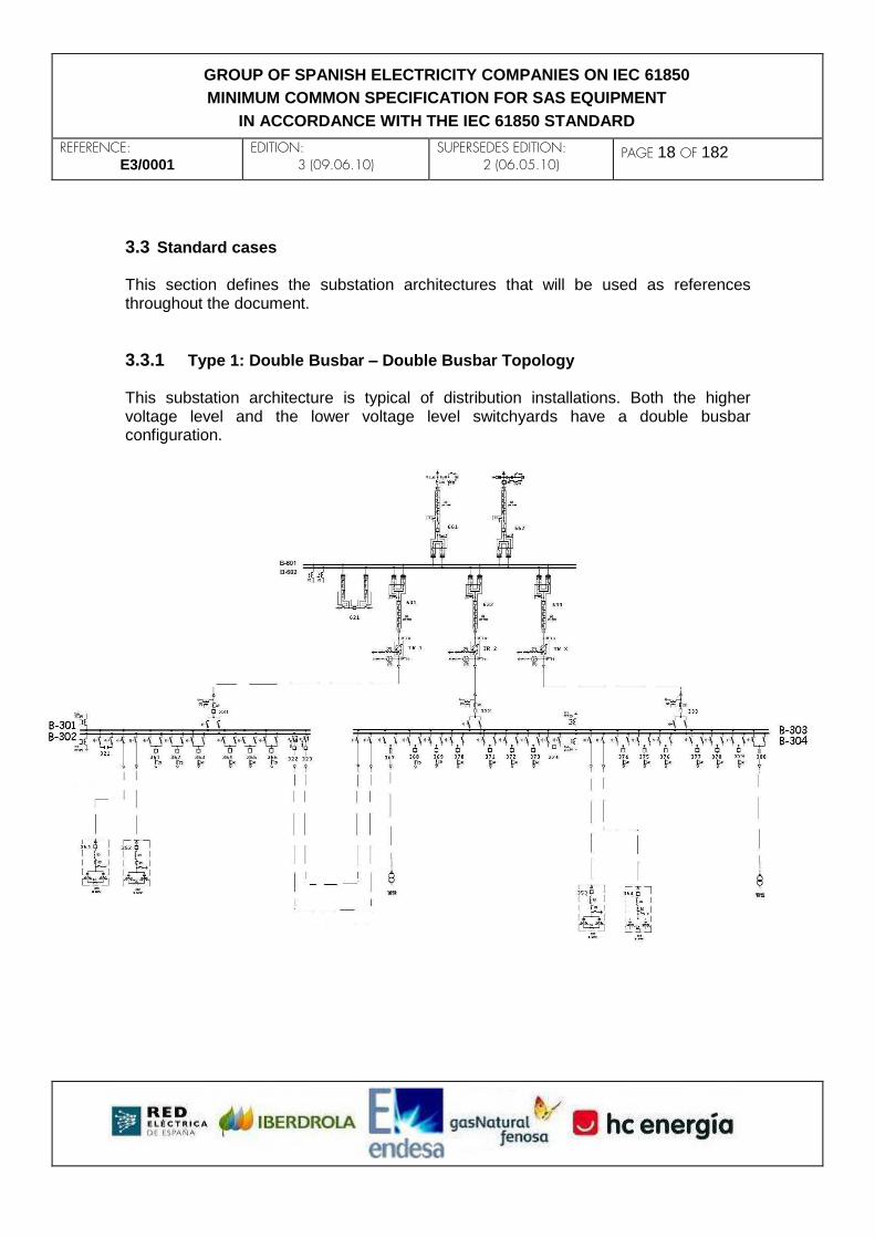
3.3 Standard cases This section defines the substation architectures that will be used as references throughout the document.
3.3.1 Type 1: Double Busbar – Double Busbar Topology This substation architecture is typical of distribution installations. Both the higher voltage level and the lower voltage level switchyards have a double busbar configuration.
REFERENCE: E3/0001
EDITION: 3 (09.06.10)
SUPERSEDES EDITION: 2 (06.05.10)
PAGE 19 OF 182
GROUP OF SPANISH ELECTRICITY COMPANIES ON IEC 61850
MINIMUM COMMON SPECIFICATION FOR SAS EQUIPMENT
IN ACCORDANCE WITH THE IEC 61850 STANDARD
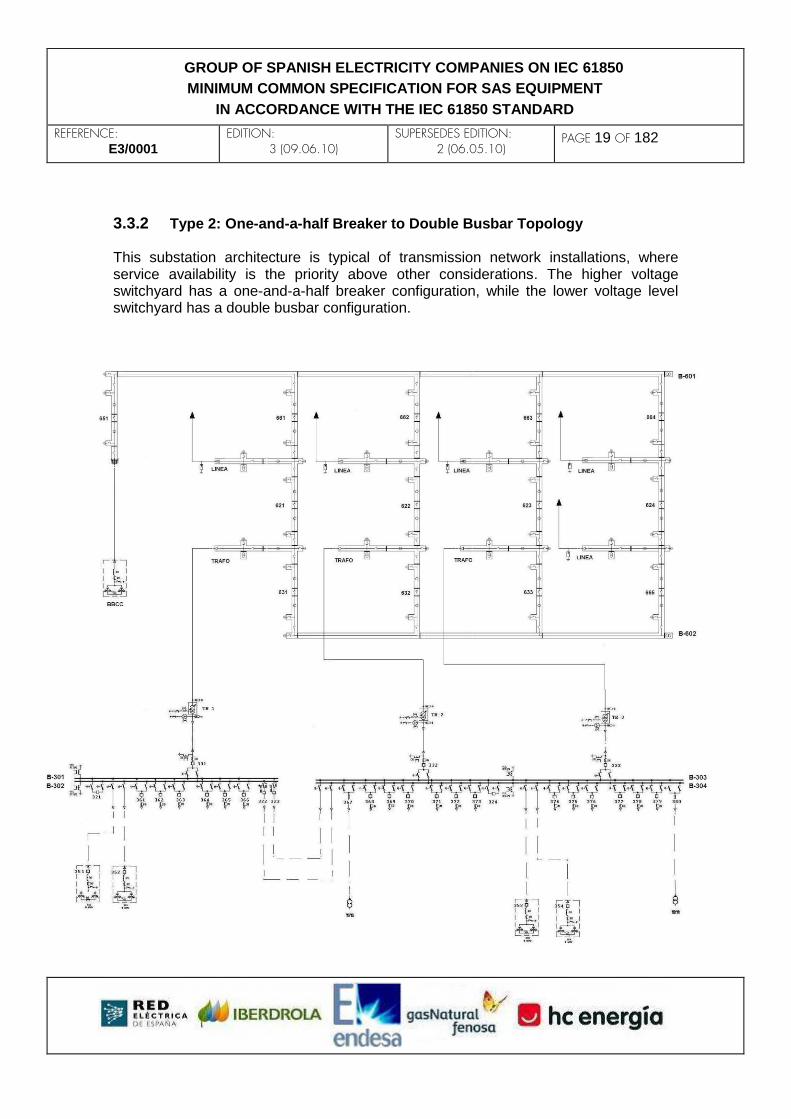
3.3.2 Type 2: One-and-a-half Breaker to Double Busbar Topology This substation architecture is typical of transmission network installations, where service availability is the priority above other considerations. The higher voltage switchyard has a one-and-a-half breaker configuration, while the lower voltage level switchyard has a double busbar configuration.

REFERENCE: E3/0001
EDITION: 3 (09.06.10)
SUPERSEDES EDITION: 2 (06.05.10)
PAGE 20 OF 182
GROUP OF SPANISH ELECTRICITY COMPANIES ON IEC 61850
MINIMUM COMMON SPECIFICATION FOR SAS EQUIPMENT
IN ACCORDANCE WITH THE IEC 61850 STANDARD
3.3.3 Type 3: H Topology This substation architecture is typical of distribution installations. The higher voltage switchyard has an H configuration as depicted in the figure, while the lower voltage level switchyard has a single busbar configuration.

REFERENCE: E3/0001
EDITION: 3 (09.06.10)
SUPERSEDES EDITION: 2 (06.05.10)
PAGE 21 OF 182
GROUP OF SPANISH ELECTRICITY COMPANIES ON IEC 61850
MINIMUM COMMON SPECIFICATION FOR SAS EQUIPMENT
IN ACCORDANCE WITH THE IEC 61850 STANDARD
3.4 Types of IED The different types of IED to which the contents of this document will be applicable are classified below.
LEVEL 0 IED: These are IEDs basically used for the capture and sending of field signals. The necessary configuration in this type of IED will be limited to communication mapping. Generally speaking, the interlockings will not be managed at this level.
LEVEL 1 IED: These are IEDs associated in general with a given bay. The interlockings will normally be managed at this level. A level 1 IED performs one or more of the following functions:
o Control
o Protection
o Measurement
Any interface devices for Telecommunication-Aided Distance Protection or for remote tripping will also be level 1 IEDs, and will comply with the specifications of this document, when applicable
LEVEL 2 IED: These are the IEDs that take care of the general functions of the substation. They use their characteristics as clients of the rest of the substation IEDs. A level 2 IED may integrate one or several of the following functions:
o SCADA control server at substation level
o General substation logics
o Configuration manager
o Gateway to remote control center
Although there are different functions to be performed by the level 2 IEDs, one should not forget that is dealing with another IED in the system and it should therefore be configured and maintained like the other IEDs of the substation.
ETHERNET SWITCH: These are the local area network nodes of the substation (switched Ethernet). For the purpose of configuration and monitoring, they will comply with the specifications of this document.
The detailed characteristics and response times of each one of the types of IED are
specified in later chapters of this document.

REFERENCE: E3/0001
EDITION: 3 (09.06.10)
SUPERSEDES EDITION: 2 (06.05.10)
PAGE 22 OF 182
GROUP OF SPANISH ELECTRICITY COMPANIES ON IEC 61850
MINIMUM COMMON SPECIFICATION FOR SAS EQUIPMENT
IN ACCORDANCE WITH THE IEC 61850 STANDARD
4. APPLICATIONS (FUNCTIONALITIES AT ELECTRICAL LEVEL) This chapter of the document indicates what current, and some future, functionalities, an electricity company requires or may require for the intelligent protection and control of its substations. The proposals expounded in this section are given by way of orientation, and although they have been agreed within the E3 group, some of them may be discarded or modified in the future, and some new ones may even appear. The ultimate objective of this section is to ascertain approximately how much information should be exchanged by the different IEDs of a substation. The present edition of this document only considers the exchange of information between IEDs located in different cabins. It is considered that the implementation of the automation protocol by means of the IEC 61850 should be carried out taking into account the criticality involved in terms of operation and safety. For this reason, the following classification is proposed, in ascending order of criticality:
Criticality I Remote control and remote access
Criticality II Protection systems
Criticality III Interlockings
Criticality IV Measurements
Criticality V Circuit breaker trips
Criticality VI Sampled Values
Besides criticality, the functionalities required are grouped according to the voltage level of an IED in a substation. There are three groups in a substation:
HV (High Voltage) Switchyard
Transformer
MV (Medium Voltage) Switchyard Throughout this section it will be seen that the functionalities required in the MV switchyard are very different to those required in the HV switchyard. The current implementations reflected in this document make it possible for the three groups to operate separately. In the future, it is not ruled out the emergence of advanced functionalities that entail interaction, for example, between the IEDs of the HV switchyard and the IEDs of the MV switchyard. Each proposal suggests an implementation. This proposal is only given by way of guidance and by no means intends to be exhaustive. A bay may contain several IEDs, although in the specific case of MV (Medium Voltage)

REFERENCE: E3/0001
EDITION: 3 (09.06.10)
SUPERSEDES EDITION: 2 (06.05.10)
PAGE 23 OF 182
GROUP OF SPANISH ELECTRICITY COMPANIES ON IEC 61850
MINIMUM COMMON SPECIFICATION FOR SAS EQUIPMENT
IN ACCORDANCE WITH THE IEC 61850 STANDARD
the most common use is a single IED per bay.
4.1 MV Switchyard
4.1.1 Criticality I 4.1.1.1 Remote control This function is needed for remote operation. 4.1.1.2 Remote access This function is needed for engineering and maintenance tasks remotely performed.
4.1.2 Criticality II 4.1.2.1 Permission for sensitive neutral tripping (Ref.MV-2.1) The I0 (neutral current) detection signal is currently wired from the cabinet associated to the transformer MV bay to all those associated to the MV line bays. It is used as a sensitive neutral trip condition. In other words, the sensitive neutral trip function in a MV line is conditioned to the presence of neutral current in the earthing of the HV/MV Transformer. An IEC 61850 implementation would reduce conventional wiring outside the control panel of the cabinet and would increase system ruggedness. 4.1.2.2 Trip of the capacitor bank breaker due to voltage MCB trip (Ref.MV-2.2) Voltage measurement is captured in the cabinet associated to transversal coupling and measurement. The voltage transformer secondaries are wired to the cabinet associated to the capacitor bank, with a Magnetothermal Circuit Breaker (MCB) protecting the circuit. This MCB has an activation-reporting contact that is also wired to the capacitor bank cabinet. The protection unit of the capacitor bank should trip whenever it detects an undervoltage condition in the measurement of the transformer secondaries, unless an activation indication from the MCB is received at the same time. In this situation, an electricity company may encounter two action philosophies:
- Option 1: Maintain service: When the voltage MCB trips, the protection unit

REFERENCE: E3/0001
EDITION: 3 (09.06.10)
SUPERSEDES EDITION: 2 (06.05.10)
PAGE 24 OF 182
GROUP OF SPANISH ELECTRICITY COMPANIES ON IEC 61850
MINIMUM COMMON SPECIFICATION FOR SAS EQUIPMENT
IN ACCORDANCE WITH THE IEC 61850 STANDARD
should generate a reporting signal, but under no circumstances should it trip the breaker connecting the capacitor bank to the busbars. It is assumed that the MCB trip is not linked to zero voltage on the busbars. In any event, resetting the MCB requires the presence of technicians, thus leading to an undesirable prolonged situation.
- Option 2: Protect the installation: When the voltage MCB trip occurs the breaker should trip (thus disconnecting the capacitor banks).
An IEC 61850 implementation would reduce conventional wiring outside the control panel of the cabinet and would increase system ruggedness. 4.1.2.3 Disturbance recording start-up (Ref.MV-2.3) Any MV protection unit shall be able to generate a disturbance recording start-up of the MV-side transformer protection IED. The user shall define in what circumstances this disturbance recording file shall be generated so as not to cause an excessive number of records to be stored in the IED. An IEC 61850 implementation may improve the analysis of certain incidents. 4.1.2.4 Logical selectivity or MV busbar protection (Ref.MV-2.4) The objective is to minimize the tripping time of the transformer protection IED when the fault is on the MV busbars. The protection systems described in this section only apply to MV level while operation is radial, i.e. without return voltage. Two different protection schemes for accomplishing the same objective are presented below. 4.1.2.4.1 Delay logic (Ref.MV-2.4.1)
The transformer, transversal coupling and longitudinal couplings instantaneous overcurrent units are enabled in permanence with a delay. This delay shall be 100 ms in transformer (to allow enough time for blocking) and 250 ms in transversal couplings and longitudinal couplings (to allow enough time for the line to trip), unless there is a pick-up of any overcurrent unit of a line, transversal coupling or longitudinal coupling that would block the instantaneous elements of the corresponding transformer, or of both the transformer and the longitudinal coupling breaker, according to whether it is closed or not.
REFERENCE: E3/0001
EDITION: 3 (09.06.10)
SUPERSEDES EDITION: 2 (06.05.10)
PAGE 25 OF 182
GROUP OF SPANISH ELECTRICITY COMPANIES ON IEC 61850
MINIMUM COMMON SPECIFICATION FOR SAS EQUIPMENT
IN ACCORDANCE WITH THE IEC 61850 STANDARD
An IEC 61850 implementation of this functionality makes it possible to clear the fault with a minimum delay, thus minimising the premature aging of the transformer, while still facilitating the selectivity of the overcurrent settings. 4.1.2.4.2 Acceleration logic (Ref.MV-2.4.2)
When the overcurrent protection of the transformer picks up, and there is no line protection reporting a pick-up, the next automation sequence should be performed:
1) Tripping order to the transversal coupling breaker (whenever it is closed).
2) If the fault persists: tripping order to the longitudinal coupling breaker of the busbar to which the transformer is connected (whenever it is closed).
3) If the fault persists: tripping order to the transformer breaker.
An IEC 61850 implementation of this functionality minimizes the premature aging of the transformer and may facilitate the selectivity of the overcurrent settings. With the information indicated in Ref.MV- 3.14, the functionality action described in this section can improve in time, i.e., if the position of the transversal coupling breaker is known and it is open, then the point 1) can be skipped and go directly on to point 2), i.e., send the tripping order to the longitudinal coupling. With the information indicated in Ref.MV- 2.8, the functionality action described in this section can improve in time, i.e., if the position of the longitudinal coupling breaker is known and it is open, then the point 2) can be skipped and go directly on to point 3), i.e., send the tripping order to the transformer breaker without further delay. With the information indicated in Ref.MV- 2.9, the functionality action described in this section can improve in time, i.e., if the position of the longitudinal coupling breaker is known and it is open, then the point 2) can be skipped and go directly on to point 3), i.e., send the tripping order to the transformer breaker without further delay. 4.1.2.5 Line breaker failure (Ref.MV-2.5) The objective is to minimize the tripping time of the transformer protection elements whenever a breaker failure occurs on a line bay. When the line protection trips and the breaker does not open within the time scheduled, the breaker failure condition is activated. The reception of this indication by the transformer-protecting IED, provided it is also detecting the fault, should activate
REFERENCE: E3/0001
EDITION: 3 (09.06.10)
SUPERSEDES EDITION: 2 (06.05.10)
PAGE 26 OF 182
GROUP OF SPANISH ELECTRICITY COMPANIES ON IEC 61850
MINIMUM COMMON SPECIFICATION FOR SAS EQUIPMENT
IN ACCORDANCE WITH THE IEC 61850 STANDARD
the following sequence of actions.
1) Tripping order to the breaker whose breaker failure condition has been started (this is only to make sure it is not a false condition caused by a setting error).
2) Tripping order to transversal coupling breaker (provided that it is closed).
3) If the fault persists: tripping order to the longitudinal coupling breaker of the busbar to which the transformer is connected (provided that it is closed).
4) If the fault persists: tripping order to the transformer breaker.
An IEC 61850 implementation of this functionality minimizes the premature aging of the transformer. 4.1.2.6 Isolation of a busbar fault or a line fault affected by a breaker failure (Ref.MV-2.6) Once a fault on the busbars or on the line affected by a breaker failure has been cleared, the aim must be to isolate the electrical connection of the busbar to the other lines and switchgear. For this purpose, all the breakers with an electrical connection to the busbar affected shall be automatically disconnected. This disconnection shall be sequenced, never performed in an all-at-a-time schedule.. Once all the breakers have been opened, all the switch disconnectors with electrical connection to the busbar affected would be automatically disconnected. This disconnection should be sequenced, never performed in an all-at-a-time schedule. An IEC 61850 implementation of this functionality reduces the number of orders to be executed by the system operator, who will find the switchyard ready to receive his service restore orders. Besides, an IEC 61850 implementation of this functionality minimizes service restoration times and may help to minimize or eliminate economic penalties due to cuts in supply.
REFERENCE: E3/0001
EDITION: 3 (09.06.10)
SUPERSEDES EDITION: 2 (06.05.10)
PAGE 27 OF 182
GROUP OF SPANISH ELECTRICITY COMPANIES ON IEC 61850
MINIMUM COMMON SPECIFICATION FOR SAS EQUIPMENT
IN ACCORDANCE WITH THE IEC 61850 STANDARD
4.1.2.7 Status signalling from the transformer breaker to the capacitor bank protection IED (Ref.MV-2.7) Due to criteria similar to those indicated in Ref.MV- 2.2, it must be sent to the IED protecting the capacitor bank. 4.1.2.8 Status signalling from the longitudinal coupling breaker of busbars 1 to the transformer protection IEDs (Ref.MV-2.8) The objective of sending this information is to expedite the activities indicated in Ref.MV- 2.4.2 4.1.2.9 Status signalling from the longitudinal coupling breaker of busbars 2 to the transformer protection IEDs (Ref.MV-2.9) The objective of sending this information is to expedite the activities indicated in Ref.MV- 2.4.2 4.1.2.10 Sending of capacitor bank breaker status change to transformer voltage regulator (Ref.MV-2.10)
When the capacitor bank breaker changes its status, it must be reported to the transformer voltage regulator for its immediate operation All the delays must be disabled in order to reach the set point voltage as soon as possible.
4.1.3 Criticality III 4.1.3.1 Permission for earthing of busbars 1 (Ref.MV-3.1) Taking into account that busbar earthing can only be carried out in the cabinet associated to the transversal coupling or the longitudinal coupling for single busbar configurations (case 3 H topology), the following clause is defined: ‘The condition for earthing busbars 1 is that there be no closed disconnector onto busbars 1’ An IEC 61850 implementation would eliminate the conventional external wiring to the cabins, reduce installation time and switchgear tests and increase system ruggedness. However, the safety assessment remains pending. 4.1.3.2 Permission for earthing of busbars 2 (Ref.MV-3.2) Same condition as Ref.MV-3.1 but for busbars 2.

REFERENCE: E3/0001
EDITION: 3 (09.06.10)
SUPERSEDES EDITION: 2 (06.05.10)
PAGE 28 OF 182
GROUP OF SPANISH ELECTRICITY COMPANIES ON IEC 61850
MINIMUM COMMON SPECIFICATION FOR SAS EQUIPMENT
IN ACCORDANCE WITH THE IEC 61850 STANDARD
This function is not applicable to single busbar configurations (case 3 H topology). 4.1.3.3 Permission for opening of the transversal coupling breaker (Ref.MV-3.3) The condition for opening the transversal coupling breaker is that there must be no coupling via the busbar-side disconnectors of any line position. An IEC 61850 implementation would eliminate the conventional external wiring to the cabins, reduce installation time and switchgear tests and increase system ruggedness. However, the safety assessment remains pending. This function is not applicable to single busbar configurations (case 3 H topology). 4.1.3.4 Permission for opening the longitudinal coupling breaker of busbars 1 (Ref.MV-3.4) The condition for opening the longitudinal coupling breaker is that the transversal coupling breaker be open. This condition only applies to double busbar switchyards linked by longitudinal couplings where there is a transversal coupling in only one side. An IEC 61850 implementation would eliminate the conventional external wiring to the cabins, reduce installation time and switchgear tests and increase system ruggedness. However, the safety assessment remains pending. This function is not applicable to single busbar configurations (case 3 H topology). 4.1.3.5 Permission for opening the longitudinal coupling breaker of busbars 2 (Ref.MV-3.5) Same condition as Ref.MV-3.4 but for busbars 2. This function is not applicable to single busbar configurations (case 3 H topology). 4.1.3.6 Permission for closing the disconnector of busbars 1 with that of busbars 2 closed (Ref.MV-3.6) The condition is that the transversal coupling breaker be closed, i.e.: (Disconnector of busbars 1 closed AND breaker closed AND disconnector of busbars 2 closed). Unlike the information supplied in Ref.MV- 3.14, this information may be conditioned to

REFERENCE: E3/0001
EDITION: 3 (09.06.10)
SUPERSEDES EDITION: 2 (06.05.10)
PAGE 29 OF 182
GROUP OF SPANISH ELECTRICITY COMPANIES ON IEC 61850
MINIMUM COMMON SPECIFICATION FOR SAS EQUIPMENT
IN ACCORDANCE WITH THE IEC 61850 STANDARD
an express authorization if the company so requires, i.e., even if the transversal coupling has been performed, this coupling cannot be reported until the express authorization is activated. An IEC 61850 implementation would eliminate the conventional external wiring to the cabins, reduce installation time and switchgear tests and increase system ruggedness. However, the safety assessment remains pending This function is not applicable to single busbar configurations (case 3 H topology). 4.1.3.7 Permission for closing the disconnector of busbars 2 with that of busbars 1 closed (Ref.MV-3.7) Same condition as Ref.MV-3.6 but for busbars 2. This function is not applicable to single busbar configurations (case 3 H topology). 4.1.3.8 Permission for Closing the disconnector of busbars 1 (Ref.MV-3.8) The condition is that busbar 1 not be earthed. An IEC 61850 implementation would eliminate the conventional external wiring to the cabins, reduce installation time and switchgear tests and increase system ruggedness. However, the safety assessment remains pending 4.1.3.9 Permission for closing the switch disconnector of busbars 2 (Ref.MV-3.9) Same condition as Ref.MV-3.8 but for busbars 2. This function is not applicable to single busbar configurations (case 3 H topology). 4.1.3.10 SF6-underpressure trip and/or blocking command for Busbars 1 (Ref.MV-3.10) This signal is sent to all the bays of the switchyard when the SF6 underpressure alarm or trip is activated. Upon reception of this signal, the protection IEDs may perform one or any of the following three actions:
1) Trip the breaker.
2) Block the possible closing of the breaker.
3) No action.

REFERENCE: E3/0001
EDITION: 3 (09.06.10)
SUPERSEDES EDITION: 2 (06.05.10)
PAGE 30 OF 182
GROUP OF SPANISH ELECTRICITY COMPANIES ON IEC 61850
MINIMUM COMMON SPECIFICATION FOR SAS EQUIPMENT
IN ACCORDANCE WITH THE IEC 61850 STANDARD
4.1.3.11 SF6-underpressure trip and/or blocking command for busbars 2 (Ref.MV-3.11) Same condition Ref.MV-3.10 but for busbars 2. This function is not applicable to single busbar configurations (case 3 H topology). 4.1.3.12 SF6-underpressure alarm or trip for busbars 1 (Ref.MV-3.12) For those MV cabinet control projects featuring SF6 underpressure alarm or trip signalling in every bay (and not concentrated in the transversal coupling cabinet), this information has to be sent to the transversal coupling so that, depending on the requirements of each company, Ref.MV- 3.10 can be applied. 4.1.3.13 SF6-underpressure alarm or trip for busbars 2 (Ref.MV-3.13) Same condition Ref.MV-3.12 but for busbars 2. This function is not applicable to single busbar configurations (case 3 H topology). 4.1.3.14 Transversal coupling status closed (Ref.MV-3.14) The information that the transversal coupling is closed will be sent when the switch disconnector of busbars 1, the breaker and the switch disconnector of busbars 2 are all closed. This information will allow the transformer protection IEDs to expedite the operations indicated in Ref.MV-2.4.2, thus minimising fault time in MV busbars. This function is not applicable to single busbar configurations (case 3 H topology). 4.1.3.15 Transformers in parallel regulation detection (Ref.MV-3.15) Currently, there is a switch that activates the parallel operation of two regulators. With IEC 61850, this control could be done automatically from the breaker and switch disconnector statuses. An IEC 61850 implementation would mean that a technician would not have to travel to activate/deactivate the mentioned switch in situ. Also it would reduce conventional wiring outside the cabinet and would increase system ruggedness.

REFERENCE: E3/0001
EDITION: 3 (09.06.10)
SUPERSEDES EDITION: 2 (06.05.10)
PAGE 31 OF 182
GROUP OF SPANISH ELECTRICITY COMPANIES ON IEC 61850
MINIMUM COMMON SPECIFICATION FOR SAS EQUIPMENT
IN ACCORDANCE WITH THE IEC 61850 STANDARD
4.1.4 Criticality IV 4.1.4.1 Sending of MV busbar voltage measurement to MV IEDs (Ref.MV-4.1) MV busbar voltage measurement will be sent to every MV IED in order to compute calculated measurements like active power, reactive power, etc. This measurements will not be used for critical functions such as protection or voltage regulation. An IEC 61850 implementation would eliminate conventional wiring outside the cabinet and would increase system ruggedness. It shall avoid to install some voltage transformers reducing the cost of the project. 4.1.4.2 Regulation of transformers in parallel (Ref.MV-4.3) Currently, vendors propose their proprietary protocols for exchanging information between items of equipment to regulate transformers in parallel. The IEC 61850 implementation of this functionality would spare a parallel communication infrastructure (a specific wiring) and would ensure the interoperability of devices from different vendors.
4.1.5 Criticality V Currently, there is no possibility of applying this phase given the current state-of-the-art of both the available IEC 61850 IEDs and the switched network configurations that can be implemented at the moment. Whenever no incidence is occurring on the network the transmission times of this trip may be accepted. However, delays in transmission of a trip order due, for example, to the resetting of the LAN switches to which the IED causing the trip is connected cannot be assumed. This posture will be reconsidered when port redundancy in the IEDs and switch redundancy on the network have evolved, and when the amortization of the cost increment which this network architecture and new equipment is going to involve has been studied.
4.1.6 Criticality VI
It is not considered. It will only apply to the process bus (chapter 10) and it will depend on its future evolution.

REFERENCE: E3/0001
EDITION: 3 (09.06.10)
SUPERSEDES EDITION: 2 (06.05.10)
PAGE 32 OF 182
GROUP OF SPANISH ELECTRICITY COMPANIES ON IEC 61850
MINIMUM COMMON SPECIFICATION FOR SAS EQUIPMENT
IN ACCORDANCE WITH THE IEC 61850 STANDARD
4.2 Transformer The IEDs associated with the transformer do not need to be located in the same control cabinet. In fact, the ease of exchanging information between the IED equipment with IEC 61850 may suggest that new locations should be sought for certain IEDs. This document addresses the exchange of information between the IEDs related to the HV side of the transformer and the IEDs related to the MV side of the same transformer, which might not be located in the actual transformer control cabinet. More specifically, it considers the possibility that the transformer voltage regulator and the MV multifunction equipment (phase overcurrent, neutral, etc.) be located in the control panel of the MV cabins. This is only a consideration and in no case is it mandatory to modify current control projects. This document also addresses the need to exchange information between the IEDs of different transformers in the same substation.
4.2.1 Criticality I 4.2.1.1 Remote control Same definition as described for the MV switchyard 4.2.1.2 Remote access Same definition as described for the MV switchyard
4.2.2 Criticality II 4.2.2.1 Disturbance recording start-up (Ref.TR-2.1) All transformer protection IEDs shall be able to send a disturbance recording start-up order to each other. For example, a MV protection IED shall be able to send a disturbance recording start-up order to the HV-side and machine protection IEDs corresponding to the transformer position it belongs to. The circumstances in which this recording shall be generated will be selected so as not to cause an excessive number of records, which would lead to the loss of stored records that are of major interest. An IEC 61850 implementation may improve the analysis of certain incidents. 4.2.2.2 Reconnection due to termination of Frequency load shedding (81) (Ref.TR 2.2)

REFERENCE: E3/0001
EDITION: 3 (09.06.10)
SUPERSEDES EDITION: 2 (06.05.10)
PAGE 33 OF 182
GROUP OF SPANISH ELECTRICITY COMPANIES ON IEC 61850
MINIMUM COMMON SPECIFICATION FOR SAS EQUIPMENT
IN ACCORDANCE WITH THE IEC 61850 STANDARD
The frequency-based load-shedding functionality corresponding to the HV protection of the transformer generates first the blocking and then the closure of the MV breaker of the transformer once the conditions that had generated the load-shedding trips have disappeared. For the complete analysis of this functionality please consult Ref.TR 2.3 . 4.2.2.3 Topological status of the MV breaker for frequency load shedding (81) (Ref.TR 2.3) The frequency-based load-shedding functionality corresponding to the HV protection of the transformer will receive the MV breaker topological status to be able to perform the logics required for it to work properly. For the complete analysis of this functionality please consult Ref.TR 2.2 .
4.2.3 Criticality III 4.2.3.1 Blocking of the HV-side switch disconnector (Ref.TR 3.1) The MV-side transformer protection IED generates a block to the HV-side IED. The closure of the switch disconnector at the HV side of the transformer shall be blocked whenever,
1) the breaker at the MV side is closed, or
2) the MV busbar switch disconnector is closed, or
3) the earthing switch disconnector at the MV side is closed, or
4) there is a crank inserted.
4.2.3.2 Blocking of regulator and MV breakers in the standard configuration Type 3 (H topology) (Ref.TR 3.2) The IED of a transformer position should send a blocking signal to prevent the closure of both the MV breaker and the IED voltage regulator automatism caused by a machine trip (86).

REFERENCE: E3/0001
EDITION: 3 (09.06.10)
SUPERSEDES EDITION: 2 (06.05.10)
PAGE 34 OF 182
GROUP OF SPANISH ELECTRICITY COMPANIES ON IEC 61850
MINIMUM COMMON SPECIFICATION FOR SAS EQUIPMENT
IN ACCORDANCE WITH THE IEC 61850 STANDARD
4.2.4 Criticality IV 4.2.4.1 Sending of voltage measurement from the measurement cabinet to the transformer cabinet (Ref.TR 4.1) There are projects in which the transformer cabinet is not supplied with voltage transformers. The voltage transformer secondary windings located in the measurement cabinet are wired to the transformer cabinet. Currently, the transformer cabinet must be adapted to be able to receive the transformer secondary windings from the measurement cabinet. It is then possible to regulate voltage from this voltage measurement, whilst the calculation of active and reactive power can be obtained from this voltage measurement plus the current measurement from the transformer cabinet itself. An IEC 61850 implementation would reduce conventional wiring outside the cabinet and would increase system ruggedness.
4.2.5 Criticality V Same definition as described for the MV switchyard.
4.2.6 Criticality VI
It is not considered. It will only apply to the process bus (chapter 10) and it will depend on its future evolution.
4.3 HV Switchyard
4.3.1 Criticality I 4.3.1.1 Remote control Same definition as described for the MV Switchyard 4.3.1.2 Remote access Same definition as described for the MV switchyard
4.3.2 Criticality II
REFERENCE: E3/0001
EDITION: 3 (09.06.10)
SUPERSEDES EDITION: 2 (06.05.10)
PAGE 35 OF 182
GROUP OF SPANISH ELECTRICITY COMPANIES ON IEC 61850
MINIMUM COMMON SPECIFICATION FOR SAS EQUIPMENT
IN ACCORDANCE WITH THE IEC 61850 STANDARD
4.3.2.1 Disturbance recording start-up (Ref.HV 2.1) Any HV protection unit shall be able to generate a disturbance recording start-up of the other HV-side protection IEDs. The user shall define in what circumstances this disturbance recording file shall be generated so as not to cause an excessive number of records to be stored in the IED. The implementation may improve the analysis of certain incidents. 4.3.2.2 Reception of zone acceleration (Ref.HV 2.2) A HV line protection IED shall receive an IEC 61850 signal from the TADP (Telecommunication-Aided Distance Protection) interface. The IEC 61850 implementation would eliminate wiring between the protection IED and the communications equipment. 4.3.2.3 Emission of zone acceleration (Ref.HV 2.3) Analogous of Ref.HV 2.2. 4.3.2.4 Remote tripping order reception (Ref.HV 2.4) Analogous of Ref.HV 2.2. 4.3.2.5 Remote tripping order emission (Ref.HV 2.5) Analogous of Ref.HV 2.2. 4.3.2.6 Putting synchronism detection in/out of service (Ref.HV 2.6) An IED shall send an IEC 61850 signal to all the HV switchyard IEDs to put synchronism detection in/out of service at the operator's will. An IEC 61850 implementation would eliminate wiring between IEDs. 4.3.2.7 Putting frequency-based load shedding in/out of service (Ref.HV 2.7) An IED will send an IEC 61850 signal to all the HV-side IEDs corresponding to the transformer to put the frequency-based load-shedding function in/out of service at the operator's will. An IEC 61850 implementation would eliminate wiring between IEDs.

REFERENCE: E3/0001
EDITION: 3 (09.06.10)
SUPERSEDES EDITION: 2 (06.05.10)
PAGE 36 OF 182
GROUP OF SPANISH ELECTRICITY COMPANIES ON IEC 61850
MINIMUM COMMON SPECIFICATION FOR SAS EQUIPMENT
IN ACCORDANCE WITH THE IEC 61850 STANDARD
4.3.3 Criticality III 4.3.3.1 Permission for earthing of busbars 1 (Ref.HV 3.1) The same functionality as described for MV applies (Ref.MV 3.1). 4.3.3.2 Permission for earthing of busbars 2 (Ref.HV 3.2) The same functionality as described for MV applies (Ref.MV 3.2). 4.3.3.3 Permission for opening the transversal coupling breaker (Ref.HV 3.3) The same functionality as described for MV applies (Ref.MV 3.3). 4.3.3.4 Permission for closing the switch disconnector of busbars 1 with that of busbars 2 closed (Ref.HV 3.6) The same functionality as described for MV applies (Ref.MV 3.6). 4.3.3.5 Permission for closing the switch disconnector of busbars 2 with that of busbars 1 closed (Ref.HV 3.7) The same functionality as described for MV applies (Ref.MV 3.7). 4.3.3.6 Permission for closing the switch disconnector of busbars 1 (Ref.HV 3.8) The same functionality as described for MV applies (Ref.MV 3.8). 4.3.3.7 Permission for closing the switch disconnector of busbars 2 (Ref.HV 3.9) The same functionality as described for MV applies (Ref.MV 3.9). 4.3.3.8 Blocking of the HV breakers in the standard case 3 (H topology) (Ref.HV 3.20) The IED of a transformer position should send the blocking of the possible closure of both the HV line breaker and the transversal coupling breaker configuration caused by a machine trip (86). An IEC 61850 implementation would eliminate wiring between IEDs.

REFERENCE: E3/0001
EDITION: 3 (09.06.10)
SUPERSEDES EDITION: 2 (06.05.10)
PAGE 37 OF 182
GROUP OF SPANISH ELECTRICITY COMPANIES ON IEC 61850
MINIMUM COMMON SPECIFICATION FOR SAS EQUIPMENT
IN ACCORDANCE WITH THE IEC 61850 STANDARD
4.3.3.9 Status signalling from the HV longitudinal coupling breaker to frequency load shedding (81) in the standard configuration Type 3 (H topology) (Ref.HV 3.21) The busbar 1 and 2 voltage measurements are sent to the frequency load shedding IED, located in the HV transformer cabinet. Considering the HV longitudinal coupling breaker status this IED can choose the correct voltage measurement to be used for checking the frequency. An IEC 61850 implementation would reduce conventional wiring outside the cabinet and would increase system ruggedness. 4.3.3.10 Blocking of the HV breakers in the standard configuration type 3 (H topology) (Ref.HV 3.22) The transformer IED should send the blocking of the opening and closing of both the HV line breaker and the transversal coupling breaker when HV transformer switch is open. An IEC 61850 implementation would eliminate wiring between IEDs.
4.3.4 Criticality IV
No implementation is required, at least in this version.
4.3.5 Criticality V Same definition as described for the MV switchyard.
4.3.6 Criticality VI
It is not considered. It will only apply to the process bus (chapter 10) and it will depend on its future evolution.

REFERENCE: E3/0001
EDITION: 3 (09.06.10)
SUPERSEDES EDITION: 2 (06.05.10)
PAGE 38 OF 182
GROUP OF SPANISH ELECTRICITY COMPANIES ON IEC 61850
MINIMUM COMMON SPECIFICATION FOR SAS EQUIPMENT
IN ACCORDANCE WITH THE IEC 61850 STANDARD
4.4 Graphic representation of the exchange of information The following figures reflect graphically the exchange of information for the two most significant of the standard cases, with regard to the complexity and amount of signalling involved.
4.4.1 Diagram of the application to standard case 1: Double Busbar – Double Busbar Topology

REFERENCE: E3/0001
EDITION: 3 (09.06.10)
SUPERSEDES EDITION: 2 (06.05.10)
PAGE 39 OF 182
GROUP OF SPANISH ELECTRICITY COMPANIES ON IEC 61850
MINIMUM COMMON SPECIFICATION FOR SAS EQUIPMENT
IN ACCORDANCE WITH THE IEC 61850 STANDARD
4.4.2 Diagram of the application to standard case 2: One-and-a-half Breaker to Double Busbar Topology The corresponding diagram for this topology is not depicted in this section because this case is included in the analysis performed in the other two cases.
4.4.3 Diagram of the application to standard case 3: H Topology

REFERENCE: E3/0001
EDITION: 3 (09.06.10)
SUPERSEDES EDITION: 2 (06.05.10)
PAGE 40 OF 182
GROUP OF SPANISH ELECTRICITY COMPANIES ON IEC 61850
MINIMUM COMMON SPECIFICATION FOR SAS EQUIPMENT
IN ACCORDANCE WITH THE IEC 61850 STANDARD
5. LAN TOPOLOGY FOR THE STATION BUS This section discusses the different Local Area Network (LAN) topologies applicable to an IEC-61850-automated substation, including the concepts of redundancy and needed network features of IEDs. The network topologies described here are based on the following requirements:
recovery time As defined in IEC 62439.
redundancy As defined in IEC 62439.
deterministic The guarantee that the recovery time remains below a certain value as long as the basic assumptions are met. (From IEC 62439)
robustness As defined and classified in IEC 62439.
fault tolerance How many and what failures at a time can happen that are not overcome by redundancy.
economical aspects
As determined by each company according to its own criteria.
Only two topologies will be analysed in the present edition of this document, namely the multi-ring collar and the redundant double star. The single ring and the single star topologies are implicitly contemplated as straightforward instantiations of the former and the latter, respectively.
5.1 Multi-ring collar topology or redundant master switch The requirements met with this topology are the following:
recovery time Around 50 ms for GOOSE messaging in a multi-ring collar topology.
redundancy No redundant LAN.
One redundant leaf.
deterministic No
robustness All end nodes remain able to communicate (with possibly some interruption) in case of single link failure. All but a few remain able to communicate (with possibly some interruption) in case of single switch failure.
fault tolerance Single failure of an inter-switch link at a time.

REFERENCE: E3/0001
EDITION: 3 (09.06.10)
SUPERSEDES EDITION: 2 (06.05.10)
PAGE 41 OF 182
GROUP OF SPANISH ELECTRICITY COMPANIES ON IEC 61850
MINIMUM COMMON SPECIFICATION FOR SAS EQUIPMENT
IN ACCORDANCE WITH THE IEC 61850 STANDARD
economical aspects
Due to the big number of bays, the number of switches has to be reduced to be economically attractive.
5.1.1 Description of the topology The departure point for multi-ring collar topology is a single ring, which, due to the large size of the substations in which it is applied, has to be split into several smaller rings. All these rings are interconnected by means of a couple of master switches.
5.1.2 Physical interconnection diagram The following figure shows the simplest case of this topology, namely that in which the collar comprises a single ring:

REFERENCE: E3/0001
EDITION: 3 (09.06.10)
SUPERSEDES EDITION: 2 (06.05.10)
PAGE 42 OF 182
GROUP OF SPANISH ELECTRICITY COMPANIES ON IEC 61850
MINIMUM COMMON SPECIFICATION FOR SAS EQUIPMENT
IN ACCORDANCE WITH THE IEC 61850 STANDARD
The master switch will be connected to the gateway to the remote control centre and the redundant master switch to the local control terminal (HMI). In this way, if a master switch fails the installation can be operated through the gateway or HMI. The network ring configuration and the master switch redundancy guarantees that if one of the LAN switches becomes inactive, the hosts attached to the other switches still have at least one physical path to each other. In view of the possible number of LAN switches in a substation it becomes necessary to create several rings to minimize the number of switches per ring as far as possible. This segregation also increases system availability and facilitates maintainability. The following figure schematically shows a more complex case of the multi-ring collar topology.

REFERENCE: E3/0001
EDITION: 3 (09.06.10)
SUPERSEDES EDITION: 2 (06.05.10)
PAGE 43 OF 182
GROUP OF SPANISH ELECTRICITY COMPANIES ON IEC 61850
MINIMUM COMMON SPECIFICATION FOR SAS EQUIPMENT
IN ACCORDANCE WITH THE IEC 61850 STANDARD
5.1.3 Fibre-optic communication in the substation For every ring, the LAN switches (and therefore the cabins hosting them) will be linked consecutively by means of fibre-optic cables. Typically, there will be a single LAN switch in every cabinet, although this topology does not exclude the existence of multiple switches per cabinet, in which case the switches would also be sequentially connected inside the cabinet. One end of the resulting total chain will be linked to the main master switch and the other end to the redundant master switch, thus physically closing the ring.

REFERENCE: E3/0001
EDITION: 3 (09.06.10)
SUPERSEDES EDITION: 2 (06.05.10)
PAGE 44 OF 182
GROUP OF SPANISH ELECTRICITY COMPANIES ON IEC 61850
MINIMUM COMMON SPECIFICATION FOR SAS EQUIPMENT
IN ACCORDANCE WITH THE IEC 61850 STANDARD
The optical fibre laid between each end and their respective master switch should travel along different physical paths.
5.1.4 LAN redundancy This topology ensures that the failure of a LAN switch, be it a master or a cabinet one, leaves the hosts which are connected directly to it isolated and without connectivity, but the other switches of the ring will have an alternative path to access any other switch. Moreover, the failure of a single link between switches will not leave any equipment without connectivity. Initially, ring redundancy for the HV level and Transformer is not addressed because of economic cost and installation complexity. The redundancy protocol will be Rapid Spanning Tree Protocol (RSTP) to guarantee compatibility between different vendors.
5.1.5 Equipment By way of example, for the following substation:
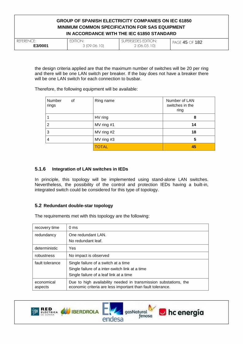
REFERENCE: E3/0001
EDITION: 3 (09.06.10)
SUPERSEDES EDITION: 2 (06.05.10)
PAGE 45 OF 182
GROUP OF SPANISH ELECTRICITY COMPANIES ON IEC 61850
MINIMUM COMMON SPECIFICATION FOR SAS EQUIPMENT
IN ACCORDANCE WITH THE IEC 61850 STANDARD
the design criteria applied are that the maximum number of switches will be 20 per ring and there will be one LAN switch per breaker. If the bay does not have a breaker there will be one LAN switch for each connection to busbar. Therefore, the following equipment will be available:
Number of rings
Ring name Number of LAN switches in the
ring
1 HV ring 8
2 MV ring #1 14
3 MV ring #2 18
4 MV ring #3 5
TOTAL 45
5.1.6 Integration of LAN switches in IEDs In principle, this topology will be implemented using stand-alone LAN switches. Nevertheless, the possibility of the control and protection IEDs having a built-in, integrated switch could be considered for this type of topology.
5.2 Redundant double-star topology The requirements met with this topology are the following:
recovery time 0 ms
redundancy One redundant LAN.
No redundant leaf.
deterministic Yes
robustness No impact is observed
fault tolerance Single failure of a switch at a time
Single failure of a inter-switch link at a time
Single failure of a leaf link at a time
economical aspects
Due to high availability needed in transmission substations, the economic criteria are less important than fault tolerance.

REFERENCE: E3/0001
EDITION: 3 (09.06.10)
SUPERSEDES EDITION: 2 (06.05.10)
PAGE 46 OF 182
GROUP OF SPANISH ELECTRICITY COMPANIES ON IEC 61850
MINIMUM COMMON SPECIFICATION FOR SAS EQUIPMENT
IN ACCORDANCE WITH THE IEC 61850 STANDARD
5.2.1 Description of the topology As its name indicates, the redundant double-star topology consists of a pair of independent and closed star LANs, which will be called LAN A and LAN B, so that every IED will have two Ethernet ports through which it will be connected to each LAN, respectively. On the basis of the standard case 2 (one-and-a-half breaker to double busbar), defined in section 3.2 of the document, the IEDs present the following layout:
1) At bay level, there will be one bay for every one-and-a-half breaker diameter. All the telecommunications, remote control and protection IEDs necessary for the diameter to operate will be inside the bay.
2) At station level, there will be one or several level 2 IEDs.
The following figure shows the configuration of the bay level for the one-and-a-half breaker diameters of standard case 2.

REFERENCE: E3/0001
EDITION: 3 (09.06.10)
SUPERSEDES EDITION: 2 (06.05.10)
PAGE 47 OF 182
GROUP OF SPANISH ELECTRICITY COMPANIES ON IEC 61850
MINIMUM COMMON SPECIFICATION FOR SAS EQUIPMENT
IN ACCORDANCE WITH THE IEC 61850 STANDARD
5.2.2 Physical interconnection diagram The redundant double-star topology diagram is shown below. Three bays have been drawn, and will correspond to 3 diameters. LAN A is shown in red colour, while LAN B is shown in blue colour.

REFERENCE: E3/0001
EDITION: 3 (09.06.10)
SUPERSEDES EDITION: 2 (06.05.10)
PAGE 48 OF 182
GROUP OF SPANISH ELECTRICITY COMPANIES ON IEC 61850
MINIMUM COMMON SPECIFICATION FOR SAS EQUIPMENT
IN ACCORDANCE WITH THE IEC 61850 STANDARD
Each IED is connected to the closest switch of each network by means of two independent Ethernet ports. The connection between the bay switches and the IEDs in the same bay can be done by UTP Cat 5E cable with RJ-45 connectors. The connection of the bay switches to the station ones is effected through the multimode optical fibre of the substation. The station switches and the level 2 IEDs can be connected by means of either optical fibre or UTP Cat 5E cable with RJ-45 connectors.
5.2.3 Fibre-optic communication in substation In substations of this kind there will be, generally speaking, two independent multimode fibre-optic networks that link the bays to the station level. Each network (normally called track 1 and track 2) use independent physical paths through the conduits of the

REFERENCE: E3/0001
EDITION: 3 (09.06.10)
SUPERSEDES EDITION: 2 (06.05.10)
PAGE 49 OF 182
GROUP OF SPANISH ELECTRICITY COMPANIES ON IEC 61850
MINIMUM COMMON SPECIFICATION FOR SAS EQUIPMENT
IN ACCORDANCE WITH THE IEC 61850 STANDARD
substation and is carried by independent optical fibre hoses. In a few words, from one bay there will be two independent communication tracks towards the station level. The number of fibre-optic services of these tracks depends on the needs of every substation. In the case of a redundant double star, this duplicity will be leveraged to create LAN A on network track 1, and LAN B on the network track 2. Each one of the LANs needs 2 optical fibres (one for transmission, another for reception) plus 2 optical fibres as backup between each bay and the station level. It should be noted that the configuration of each multimode fibre-optic network is in itself a star. If someone wishes to link two bays to each other by means of fibre optics, it would be necessary to go up to the station level and make the necessary splices at that level.
5.2.4 LAN redundancy To obtain total LAN redundancy and leverage the full physical redundancy described above, it will be necessary to use a redundancy protocol that guarantees an instant recovery time. In this regard, the PRP protocol specified in the IEC 62439 standard will be used. In the future, other redundancy protocols proposed by the IEC 61850 standard will be assessed.
5.2.5 Equipment In order to create the redundant double star, LAN switches will be required at both the bay level and the station level. In view of the hub nature of the station level in this topology, the station level switches must have greater capacity. The use of several switches connected to each other could even be addressed for big enough substations. By way of example, suppose a one-and-a-half breaker substation topology with five diameters, as shown in 5.2.1. In this case, the following level 0 and 1 equipment will be located for one diameter:
1) 1 level 1 IED with client IEC 61850 functions for the local remote control of the full diameter.
2) 1 level 1 IED for the protection of the central breaker.
3) 3 level 1 IEDs for primary, secondary and breaker protection of each one of the line bays.
4) 1 level 1 IED for a busbar differential protection (only two diameters with this IED).
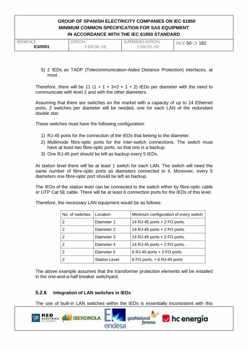
REFERENCE: E3/0001
EDITION: 3 (09.06.10)
SUPERSEDES EDITION: 2 (06.05.10)
PAGE 50 OF 182
GROUP OF SPANISH ELECTRICITY COMPANIES ON IEC 61850
MINIMUM COMMON SPECIFICATION FOR SAS EQUIPMENT
IN ACCORDANCE WITH THE IEC 61850 STANDARD
5) 2 IEDs as TADP (Telecommunication-Aided Distance Protection) interfaces, at most .
Therefore, there will be 11 (1 + 1 + 3×2 + 1 + 2) IEDs per diameter with the need to communicate with level 2 and with the other diameters. Assuming that there are switches on the market with a capacity of up to 24 Ethernet ports, 2 switches per diameter will be needed, one for each LAN of the redundant double star. These switches must have the following configuration:
1) RJ-45 ports for the connection of the IEDs that belong to the diameter.
2) Multimode fibre-optic ports for the inter-switch connections. The switch must have at least two fibre-optic ports, so that one is a backup.
3) One RJ-45 port should be left as backup every 5 IEDs.
At station level there will be at least 1 switch for each LAN. The switch will need the same number of fibre-optic ports as diameters connected to it. Moreover, every 5 diameters one fibre-optic port should be left as backup. The IEDs of the station level can be connected to the switch either by fibre-optic cable or UTP Cat 5E cable. There will be at least 6 connection ports for the IEDs of this level. Therefore, the necessary LAN equipment would be as follows:
No. of switches Location Minimum configuration of every switch
2 Diameter 1 14 RJ-45 ports + 2 FO ports.
2 Diameter 2 14 RJ-45 ports + 2 FO ports.
2 Diameter 3 14 RJ-45 ports + 2 FO ports.
2 Diameter 4 14 RJ-45 ports + 2 FO ports.
2 Diameter 5 6 RJ-45 ports + 2 FO ports.
2 Station Level 6 FO ports. + 6 RJ-45 ports
The above example assumes that the transformer protection elements will be installed in the one-and-a-half breaker switchyard.
5.2.6 Integration of LAN switches in IEDs The use of built-in LAN switches within the IEDs is essentially inconsistent with this

REFERENCE: E3/0001
EDITION: 3 (09.06.10)
SUPERSEDES EDITION: 2 (06.05.10)
PAGE 51 OF 182
GROUP OF SPANISH ELECTRICITY COMPANIES ON IEC 61850
MINIMUM COMMON SPECIFICATION FOR SAS EQUIPMENT
IN ACCORDANCE WITH THE IEC 61850 STANDARD
topology.
5.3 Conclusions For the standard cases 1 and 3, the multi-ring collar topology is considered as the most suitable bearing in mind the technical needs as well as the economic constraints. For the standard case 2, the application criticality suggests an implementation based on a redundant double-star topology. In view of the large amount of fibre-optic services needed, the use of bi-directional single fibre solutions (a single optical fibre for both transmission and reception) will be assessed in the future. Finally, it is the will of the E3 Group to remain open to other network topology solutions, like HSR, that might be proposed in the future by IEC or other authorized standard developers as long as these solutions comply with the requirements defined in this document.

REFERENCE: E3/0001
EDITION: 3 (09.06.10)
SUPERSEDES EDITION: 2 (06.05.10)
PAGE 52 OF 182
GROUP OF SPANISH ELECTRICITY COMPANIES ON IEC 61850
MINIMUM COMMON SPECIFICATION FOR SAS EQUIPMENT
IN ACCORDANCE WITH THE IEC 61850 STANDARD
6. ENGINEERING, EXPLOITATION AND MAINTENANCE This chapter defines the configuration of the IEDs and the management of configuration file versions. Basic rules are set to facilitate the integration of the IEDs in substations, tests, commissioning and subsequent maintenance of the installations.
6.1 Basic principles of equipment configuration
6.1.1 A single file per IED: the CID file The IEDs, whatever their type, must be totally configured with a single file, the CID. The CID, which will be coded in XML language, as indicated in part 6 of the IEC 61850 standard, should have all the information needed for the equipment to be fully configured. No IEDs that need several configuration files will be accepted.
6.1.1.1 Composition of the CID file In the more general case a CID will be comprised of two different parts:
STANDARD PART: It will contain all the functions of the IED that are modeled, and it should be possible to edit it with IEC 61850 tools (SCL editors).
PROPRIETARY PART: It will comprise all the functions that are not modeled and which must be configured only with the vendor’s tool. The ultimate objective is to reduce the proprietary part until it disappears.
Both parts shall be strictly complementary, which means that if a function is totally modeled on IEC 61850 it should not be referenced in the proprietary part.
6.1.1.2 Extension of the modeling The CID, as the single IED configuration file, must have the greatest possible part of the configuration information modeled according to IEC 61850 and therefore included in its standard part. To achieve this, the extension rules given by the standard should be applied, with a view to modeling each and every one of the functions of the IED. The ultimate objective is for the IEDs to have only a standard part. Some of the basic criteria for extending the modeling are detailed below.

REFERENCE: E3/0001
EDITION: 3 (09.06.10)
SUPERSEDES EDITION: 2 (06.05.10)
PAGE 53 OF 182
GROUP OF SPANISH ELECTRICITY COMPANIES ON IEC 61850
MINIMUM COMMON SPECIFICATION FOR SAS EQUIPMENT
IN ACCORDANCE WITH THE IEC 61850 STANDARD
APPLICATION OF ‘INREF’ DATA OBJECTS: ‘InRef’ data objects must be used mainly in logical nodes involved in control functions, for all of them to be completely modeled.
To perform its function, any logical node, in its internal logic, should use the status of other variables such as input and output statuses, results of logics, interlockings, etc.
In the protection nodes, these references to variables are generally fixed (currents, voltages), while on the other hand in the control nodes they are subject to changes between different positions (groupings of CALH alarms, XCBR/XSWI switchgear statuses, CILO blocking signals, etc.). These references to variables are settings or adjustments that change from one position to another.
These variables must be modeled by means of the inputs defined in the standard, i.e. every node must have the necessary ‘InRef’ data objects comprising all the variables the node needs to fulfil its functionality.
CONTROL LOGICS: The application of the ‘InRef’ data objects makes it possible to drastically reduce the needs for programmable control logics. The control logics should be included in the IED's firmware, so that the job of configuring the control is reduced to a mere parameterization of the control nodes, much in the same way as the protection elements (as an example: nobody would think of configuring the distance protection algorithm from scratch when adjusting a protection).
Nevertheless, it will continue to be necessary to make minor control logics (groupings, timings, etc.), that they may be modeled by means of a logical node (e.g. a LOG.GGIO), where it is possible to include a small logic in literal language in its ‘InRef’ DOs. (See Annex A for further information).
GOOSE CLIENT: This is another function that should be modeled with a Logical Node (e.g. GI.GGIO), by which it is possible to configure all the information an IED needs to subscribe to a data object of a GOOSE data set. (See Annex D for further information).
6.1.1.3 Management of the filename and date of the CID The filename of the CID shall be composed of a maximum of 32 characters including a ‘.CID’ extension. Valid characters for the filename shall be those allowed by the VISIBLE STRING datatype as defined in IEC 61850-8-1, section 8.1.2.5. The filename shall be defined by the user according to local coding standards, in order to facilitate the identification and handling of the complete set of files that will make up a whole IEC 61850 substation.
REFERENCE: E3/0001
EDITION: 3 (09.06.10)
SUPERSEDES EDITION: 2 (06.05.10)
PAGE 54 OF 182
GROUP OF SPANISH ELECTRICITY COMPANIES ON IEC 61850
MINIMUM COMMON SPECIFICATION FOR SAS EQUIPMENT
IN ACCORDANCE WITH THE IEC 61850 STANDARD
By way of example a possible coding of a CID filename is shown below: Filename mask: ‘0123456789012345678901234567.CID’
Filename : ‘P-MVCab-ON-31.CID’
In the previous example, the filename clearly identifies the CID as corresponding to a standard project (P) identified as ‘MV cabins’ (MVCab) and applied to the bay with ‘Operation Number’ (ON) 31. Another approach would be the use of a filename based on the IED name, as follows: {iedName}_{vvv}.CID (where vvv is a version sequence number)
In some other cases, the user might prefer to include in the filename the date and time when the CID file has been generated. For example, to indicate that the CID was generated on date (D) July 3rd, 2009 the filename could be as follows: Filename mask: ‘0123456789012345678901234567.CID’
Filename : ‘P-MVCab-ON-31-D-20090703.CID’
When accessing the CID-storing directories of an IED via FTP, the FTP client will show, as provided by the FTP server, the filename of the stored CIDs as well as the local IED date and time when they were last updated. In normal operation, the IED shall be synchronized via GPS. When retrieving a CID file via FTP or USB memory, the date and time of last update shall be locally generated at the destination.
6.1.2 A single file per substation: the SCD file The SCD file is the one that groups together, in a single item, all the CID files of a substation IEDs.
SCD includes (CID1 + CID2 + … + CIDn) Therefore, the SCD is the only configuration file of a substation. The SCD file may be maintained by a configuration manager who should distribute it and keep it updated. In view of the agglutinative nature of the SCD, in the course of this document, the focus will be generally placed on the analysis of the CID file.

REFERENCE: E3/0001
EDITION: 3 (09.06.10)
SUPERSEDES EDITION: 2 (06.05.10)
PAGE 55 OF 182
GROUP OF SPANISH ELECTRICITY COMPANIES ON IEC 61850
MINIMUM COMMON SPECIFICATION FOR SAS EQUIPMENT
IN ACCORDANCE WITH THE IEC 61850 STANDARD
6.1.3 Directory structure for the CID management The directory structure for the storage of the CID files in the internal non-volatile memory of the equipment will be as indicated in Appendix D of part 8-1 of the IEC 61850 standard, which proposes a root directory called SCL, which will be comprised of two subdirectories:
notvalidated: it will contain the CID files loaded in the IED from the outside (see section 6.2) which have not been validated locally by it.
validated: it is the directory that contains CIDs validated locally by the IED.
The CIDs generated internally by the IED will be located directly in ‘validated’. The CIDs loaded into the IED externally will be moved from ‘notvalidated’ to ‘validated’ when the IED successfully runs the validation process; then they will disappear from ‘notvalidated’. By means of the ACSI services, access to the SCL Control Block (see IEC 61850-8-1 Appendix D) will allow to know at all times which CID is active, which CID has been the object of the latest validation attempt and what the result of this attempt was.
6.2 IED configuration processes This section describes the processes which the external agents (specialized personnel and applications) will use to enter and modify the configuration, either totally (complete CID) or partially, in the IED.
6.2.1 Types of configuration modifications A distinction may be made between two types of modifications that can be made in an IED, depending on the mode. ‘Hot’ modifications, which are performed quickly without interrupting the IED's functionalities. They are also known as parameterization changes. They are generally adjustment or setting changes. These modifications can be made by means of the IED's integrated physical interface (if it has one), its own proprietary software tool, or the ACSI services described in IEC 61850. Therefore, they shall not require the loading of a CID file, while the IED must dynamically update its active CID file to keep it consistent at all times with the actual status of the equipment (see section 6.2.6). ‘Cold’ modifications affect the structure of the CID file (database, single-line diagrams, datasets, RCB, GCB, InRefs, proprietary parts, etc.) and are normally

REFERENCE: E3/0001
EDITION: 3 (09.06.10)
SUPERSEDES EDITION: 2 (06.05.10)
PAGE 56 OF 182
GROUP OF SPANISH ELECTRICITY COMPANIES ON IEC 61850
MINIMUM COMMON SPECIFICATION FOR SAS EQUIPMENT
IN ACCORDANCE WITH THE IEC 61850 STANDARD
performed by engineering personnel (in test and commissioning phases) and by the maintenance personnel, for tasks that go beyond a mere change of settings (replacement of faulty equipment, introduction of new functions, etc.). This type also includes modifications that require a reboot, such as hardware and firmware upgrades. ‘Cold’ modifications require the loading, validation and activation of a CID, processes which are described in the following sections.
6.2.2 Uploading and downloading files By means of the ACSI services specified in IEC 61850-8-1 Appendix D, it will be possible to upload and download a CID file to/from the IED. Nevertheless, in view of the qualities of the FTP protocol (simplicity, availability of client tools and universality), the IED must also accept the uploading and downloading of a CID file by this medium, which assumes the existence of an FTP server in the device. The IED should have a LED to show that it is being accessed by FTP. This LED should remain active throughout the FTP session and not just when a file transfer is ongoing. Moreover, the IED shall have a USB port and will also permit the uploading and downloading of the CID file by this medium. When a USB memory (pen drive) is plugged into, the IED shall automatically behave as detailed below:
If the pen drive is empty, the IED shall download its active CID and all the information held by the IED in file format: disturbance records, fault reports, sequence of events, etc.
If the pen drive contains a single CID file, the IED shall upload it automatically to ‘notvalidated’ and then shall automatically run a validation and possibly an activation (see section 6.2.4).
In any other case, the IED will perform no action.
It will not be possible, by the means described in this chapter, to delete, edit or overwrite any IED internal file. The only file that may be uploaded to the IED will be the CID file, and only in the ‘notvalidated’ directory.
6.2.3 Loading mode Assuming that the user may want to guarantee the presence of personnel at the installation and thus avoid errors in the transmission of configurations via FTP or MMS, the IED shall have, in its LPHD logical node, a modifiable parameter ‘LoadMod’ that will allow to protect the equipment from unwanted loading of CID files. This parameter (see Annex F) shall take values that shall identify the following three statuses, which are

REFERENCE: E3/0001
EDITION: 3 (09.06.10)
SUPERSEDES EDITION: 2 (06.05.10)
PAGE 57 OF 182
GROUP OF SPANISH ELECTRICITY COMPANIES ON IEC 61850
MINIMUM COMMON SPECIFICATION FOR SAS EQUIPMENT
IN ACCORDANCE WITH THE IEC 61850 STANDARD
mutually exclusive:
INDIFFERENT: The equipment shall always accept a CID file upload into the ‘notvalidated’ directory by any of the methods described in 6.2.2.
UPLOAD MODE: The equipment shall always accept a CID file upload into the ‘notvalidated’ directory by any of the methods shown in 6.2.2, but only temporarily, as described below.
PROTECTED MODE: The equipment shall not accept the uploading of the CID file into the ‘notvalidated’ directory.
The change from protected mode to upload mode shall not be possible through the ACSI services. The change from protected mode to indifferent mode and vice versa shall be allowed in this way, although possibly requiring a higher authorization profile. If the IED has an integrated physical interface (including switches, buttons and even digital inputs), the upload mode must be easy to activate by this medium, with a LED or on-screen message clearly indicating that the IED is in this status. From the foregoing it may be deduced that the upload mode is not applicable to IEDs that do not have an integrated physical interface; such equipment shall only accept the loading of a CID file when in indifferent mode. The upload mode must remain activated until one of the following events takes place, when it switches automatically to protected mode.
The equipment is reconfigured (CID file activation) for the next time.
The upload mode is deactivated by the user.
An hour has elapsed since the activation of the upload mode.
The period of one hour is set to allow for the preparation work previous to the actual configuration. If the IED has a local display and keyboard interface, it shall be possible to activate/deactivate/configure by these means the user profiles and passwords associated with file writing. In such a case, if and only if a loading process is started by the USB insertion method, the interface shall launch a confirmation dialog before the effective loading of the CID file. Read access to the CID files stored in the equipment, as well as to others directories and files of interest for the user (events, fault reports, disturbance records) will always be permitted.

REFERENCE: E3/0001
EDITION: 3 (09.06.10)
SUPERSEDES EDITION: 2 (06.05.10)
PAGE 58 OF 182
GROUP OF SPANISH ELECTRICITY COMPANIES ON IEC 61850
MINIMUM COMMON SPECIFICATION FOR SAS EQUIPMENT
IN ACCORDANCE WITH THE IEC 61850 STANDARD
6.2.4 Validation and activation processes The processes of validation and activation shall be the only ways of cold-modifying the IED. They shall comply with the specifications of IEC 61850-8-1 Appendix D, as well as the procedures that are specified below. The IED shall have, in its LPHD logical node, a modifiable parameter ‘ValActAuto’ (see Annex F) that will establish the mode in which the IED will run the validation and the activation, with both of the following being possible:
a) AUTOMATIC: automatic validation of the CID file by the IED and immediate and automatic reconfiguration (activation of the CID file) once the file has been validated.
b) CONTROLLED: controlled validation and activation of the CID file by access to the ‘validate’ and ‘activate’ attributes of the SCL Control Block element, using, for this purpose, the ACSI communications services. This mode may be used, for example, by a configuration management tool. This mode will fulfil the specifications of 61850-8-1 Annex D.
Once the CID file has been uploaded (i.e., written to the ‘notvalidated’ directory, as described in the preceding sections), the IED shall validate it, either, depending on the mode, automatically or by an order issued via the ACSI services (access to the ‘validate’ attribute of the SCL Control Block element by means of an MMS browser or a configuration management tool, if there is one). All the essential functionality of the IED shall be maintained throughout the process. When the IED functions in automatic mode, the loading of the CID file will immediately and automatically trigger a validation process. A text file with a report on the result of the process will be created in one of the user-accessible internal directories, called ‘validation_traces’. If process errors occur, the report will specify the line number of the CID file in which the error was detected and also, as applicable, the address, within the data model, of the element or the elements in error. If the process was initiated from a USB device this text file will also be copied to the device. If the validation process ends successfully, the CID file will be deleted from the ‘notvalidated’ directory and will be transferred to the ‘validated’ directory. If there is already a file with the same name in ‘validated’, the validation will fail. Once the CID file has been validated, the IED will activate it, either, depending on the mode, automatically or by order issued via the ACSI services (access to the ‘activate’ attribute of the SCL Control Block element by means of an MMS browser or a configuration management tool, if there is one).
REFERENCE: E3/0001
EDITION: 3 (09.06.10)
SUPERSEDES EDITION: 2 (06.05.10)
PAGE 59 OF 182
GROUP OF SPANISH ELECTRICITY COMPANIES ON IEC 61850
MINIMUM COMMON SPECIFICATION FOR SAS EQUIPMENT
IN ACCORDANCE WITH THE IEC 61850 STANDARD
The CID file activation process is identified with a complete reconfiguration of the IED, which will probably entail a reset of all its firmware. Nevertheless, IEDs not requiring this reset will be assessed. The sum of the CID file upload, validation and activation times shall not be longer than 5 minutes. The activation time shall not be longer than 3 minutes. The non-availability time of protection functions (including GOOSE messaging) shall be much less and anyhow it must be clearly specified by the manufacturer. A positive assessment will be made of an IED if, at switch-on time after being switched off for any reason, it does not load the entire CID file unless it has been modified, thus allowing a faster activation.
6.2.5 IP addressing Static IP addressing shall be used throughout the substation, and the allocation or change of IP of any IED must be performed in situ. Each IED will have a fixed IP address, associated explicitly with its position and functions, according to criteria defined by each installation. Therefore, the allocation of addressing will be done in the engineering phase. Below are the fundamental criteria to be fulfilled by the IEDs to be compatible with this philosophy:
The network configuration of an IED shall be easy to display and modify
from the integrated physical interface. If the IED does not have one, the
vendor must facilitate a way of obtaining and modifying this configuration
in a standard way and without the need for proprietary tools, for example
by means of text files copied in USB memories (pen drives).
The modification of an IP address shall not be possible via the ACSI
services.
In the CID file, the network configuration shall be stored in the communi-
cations section, following the provisions of the IEC 61850 standard.
Normally, the effective IP address in the equipment will be the same as
that of the active CID file.
Nevertheless, the IP address of an IED shall be independent from the
one that figures in the activated CID file, and any possible discordance
will be treated as follows:
o If the IP address is changed in an IED by means of its physical
interface (or, if the IED does not have one, by the method men-
REFERENCE: E3/0001
EDITION: 3 (09.06.10)
SUPERSEDES EDITION: 2 (06.05.10)
PAGE 60 OF 182
GROUP OF SPANISH ELECTRICITY COMPANIES ON IEC 61850
MINIMUM COMMON SPECIFICATION FOR SAS EQUIPMENT
IN ACCORDANCE WITH THE IEC 61850 STANDARD
tioned above), the IED will stop serving data in IEC 61850, but
will maintain all its network functionality, thus permitting the re-
ception of a new CID file which will eventually fix the discor-
dance.
o If an IED receives a CID file with an IP address not matching the
one currently effective, the CID file will not be validated, and
therefore the IED will maintain its IP address and the entire pre-
vious configuration.
6.2.6 Version management Apart from a single configuration file per IED, there must exist a good version control method enabling proper maintenance. The main attributes that will identify the version of the configuration of an IED unequivocally are:
LLN0.NamPlt.configRev: it univocally identifies the individual configuration of
a logical device in an IED, definitive instances of logical nodes, relationships be-
tween logical nodes, datasets, control blocks, proprietary part and one-line dia-
grams. The LLN0.NamPlt.configRev attribute will therefore be modified in the
event of any semantic change of the data model of the associated logical de-
vice or the proprietary part of the CID file. In short, any change that cannot be
done ‘hot’.
LLN0.NamPlt.paramRev: it univocally identifies the individual parameterization
of a logical device in an IED, which is the information compiled in the CID file
generated in the parameterization phase of the IED and which will include set-
tings values and configuration parameters (attributes with functional constraint
CF, SP and SG). In a few words, a change in the parameterization of the IED
may be regarded as any ‘hot’ change that can be performed without the need
for loading, validation and activation of a new CID file.
The LLN0.NamPlt.configRev and LLN0.NamPlt.paramRev attributes respond to the VisibleString255 type of data and shall use the following format:
INDEX YEAR.MONTH.DAY.HOUR:MINUTE:SECOND [EDITOR INFORMATION] The index shall be an incremental field that will increase whenever its value changes.

REFERENCE: E3/0001
EDITION: 3 (09.06.10)
SUPERSEDES EDITION: 2 (06.05.10)
PAGE 61 OF 182
GROUP OF SPANISH ELECTRICITY COMPANIES ON IEC 61850
MINIMUM COMMON SPECIFICATION FOR SAS EQUIPMENT
IN ACCORDANCE WITH THE IEC 61850 STANDARD
In this way, the date on which the last configuration or parameterization of the IED was made will be recorded, as well as the information the version management tool considers necessary to identify its configuration and source. In the event of any change in its configuration or parameterization, the IED must consequently refresh the active CID file, as well as the ‘configRev’ and ‘paramRev’ values.
6.3 Tools Several types of tools may be considered for the management of the configuration of the IEDs of a given substation. An initial classification of the type of tool would be:
STANDARD TOOLS: These are tools for modifying any function of the IED that has been modeled as an IEC 61850 function. These tools are, or are based on, SCL editors and MMS clients.
PROPRIETARY TOOLS: These are tools provided by each vendor and required for editing the proprietary part of a device’s configuration. As stated earlier, the objective shall be to reduce the need of these proprietary tools to a minimum.
Moreover, and depending on the possible types of modification, three fundamental types of tools are distinguished:
PARAMETERISATION TOOLS: These are tools for ‘hot’ change and change management, basically the IED settings. They can be classified in two types:
o GLOBAL: They manage the parameterization of settings at global level, i.e. for all the IEDs of one or several substations.
o PARTICULAR: They manage the parameterization of settings for just one IED at a time.
CONFIGURATION TOOLS: These are tools for the implementation and management of ‘cold’ changes. They can also be classified in two types:
o GLOBAL: These can be used for the complete engineering of one or several substations.
o PARTICULAR: Simpler tools, optimized to facilitate maintenance and oriented to modifications at the IED level.
TESTING TOOLS: These are tools for both protection and maintenance personnel and engineering personnel, and facilitate the tests on the IED, client

REFERENCE: E3/0001
EDITION: 3 (09.06.10)
SUPERSEDES EDITION: 2 (06.05.10)
PAGE 62 OF 182
GROUP OF SPANISH ELECTRICITY COMPANIES ON IEC 61850
MINIMUM COMMON SPECIFICATION FOR SAS EQUIPMENT
IN ACCORDANCE WITH THE IEC 61850 STANDARD
and server, allowing to simulate equipment and perform automations. This type of tools can be divided into:
o ORIENTED TOWARDS SERVER TESTING: These are tools that allow to automate the tests of the internal logic and the parameterization of the server IEDs.
o ORIENTED TOWARDS CLIENT TESTING: These are server emulation tools that allow to test the behaviour of IEDs that work basically as clients, such as the SCADA of the substations or for remote control.
The decision of what types of tools shall be used shall be an internal issue of each company, which can either select among those available on the market or develop their own in order to cover their specific needs. As it has already been said, priority will be given to IEDs whose need for proprietary tools is minimal. Equipment will be regarded as easier to integrate in a system the lesser the need to use proprietary tools for configuration.
6.4 Added value functions
6.4.1 Disturbance recording Disturbance recording will be configured by means of logical nodes defined in the IEC 61850-7-2 standard (logical nodes RDRE, RADR, RBRS and RDRS). A disturbance record will be recorded in COMTRADE format and will be stored in one of the following directories of the IED file system:
‘/LD/<ldname>/COMTRADE’, as specified in IEC 61850-8, when the disturbance record is associated to a single logical device.
‘/COMTRADE’, when the disturbance record is associated to several logical devices.
Three different ways may be used to download a disturbance record from an IED: by means of FTP service; by means of an USB memory plugged into the IED; by means of ACSI File Transfer service.
6.4.2 Sequence of events (SOE) The sequence of events recording functionality is supported on IEC 61850 by means of the Log service defined in IEC 61850-7-2. In addition to this, a readable text file stored
REFERENCE: E3/0001
EDITION: 3 (09.06.10)
SUPERSEDES EDITION: 2 (06.05.10)
PAGE 63 OF 182
GROUP OF SPANISH ELECTRICITY COMPANIES ON IEC 61850
MINIMUM COMMON SPECIFICATION FOR SAS EQUIPMENT
IN ACCORDANCE WITH THE IEC 61850 STANDARD
in an internal directory of the IED file system is required. All SOE files will be stored in a directory call ‘/SOE’. This file will be a readable mirror of the sequence of events contained in the Log service. Three different ways may be used to download the Sequence of Events file from an IED: by means of FTP service; by means of an USB memory plugged into the IED; by means of ACSI File Transfer service. The proposed format for this text file is defined in annex E.
6.4.3 Fault reports A fault report is a special summary file created from the disturbance record and sequence of events data stored during a power network fault. The main purpose of this file is to offer the technician an easier way to find out and understand what happened during the fault. Inside a fault report, predictive maintenance information could be included, for example dissolved gases and water in oil measurement, transformer temperature, etc. Furthermore, any predictive maintenance information level could generate a new fault report. The data objects and attributes contained in a fault report will be defined by means of a dataset configured in the CID file of the IED. All fault report files will be stored in a directory call ‘/FAULT_RECORDS’. Although the format of this file is not specified in this document, it must fulfil the following requirements:
1. It must contain all the data objects and attributes defined in the dataset.
2. All the information must be presented in a readable text format.
Three different ways may be used to download a fault report from an IED: by means of FTP service; by means of an USB memory plugged into the IED; by means of ACSI File Transfer service.
6.4.4 Internal event log in the IED Logging is an internal function of the IED consisting on tracing system and kernel events that happen during its operation. All log files will be stored in a directory called ‘/SYSTEM_LOG’. No restriction about size, management or number of log files will be defined in this document. However, at least the following event classes must be stored

REFERENCE: E3/0001
EDITION: 3 (09.06.10)
SUPERSEDES EDITION: 2 (06.05.10)
PAGE 64 OF 182
GROUP OF SPANISH ELECTRICITY COMPANIES ON IEC 61850
MINIMUM COMMON SPECIFICATION FOR SAS EQUIPMENT
IN ACCORDANCE WITH THE IEC 61850 STANDARD
in this kind of files:
Boot up / shutdown time and date.
CID loading, validation and activation.
Setting and parameter updates.
Internal task errors.
Diagnosis information.
Module loading errors, driver errors, Ethernet errors.
Debug information.
Security monitoring (as stated in chapter 9).
Three different ways may be used to download a log file from an IED: by means of FTP service; by means of an USB memory plugged into the IED; by means of ACSI File Transfer service.

REFERENCE: E3/0001
EDITION: 3 (09.06.10)
SUPERSEDES EDITION: 2 (06.05.10)
PAGE 65 OF 182
GROUP OF SPANISH ELECTRICITY COMPANIES ON IEC 61850
MINIMUM COMMON SPECIFICATION FOR SAS EQUIPMENT
IN ACCORDANCE WITH THE IEC 61850 STANDARD
7. COMMUNICATION SERVICES This chapter specifies, with respect to communication services, the minimum quantitative requirements that devices must satisfy. It consists of four main parts: GOOSE multicast communication, SV (sampled values) communication, MMS services (client-server), and requisites for remote access and control.
7.1 GOOSE
7.1.1 GOOSE message and dataset capacity In order to ensure the satisfaction of general-purpose multicast communication needs in most of installations, every IED will be able to publish at least 8 GOOSE with their respective GoCB (GOOSE Control Block) and to subscribe to at least 64 publishers. Regarding transmitted data, the granularity of data inclusion into the dataset will be at a DataAttribute (DA) level. This means that any non-structured FCDA (Functionally Constrained DA) of any FCD (Functionally Constrained Data) shall be able to be transmitted by a GOOSE message.
7.1.2 GOOSE Control Block configuration All the available GoCB in an IED must be configurable in the CID file. Likewise, and in particular, the GoCB name will also be configurable in the CID file. It will be required, in the CID file, so as to control the re-transmissions and to adjust them to different scenarios, the presence of the standard-defined maxTime and minTime parameters. These will be configurable as well. The timeAllowedToLive will be two times maxTime. The behaviour when an association loss occurs will also be configurable via CID file. The GOOSE sent signal could keep the value it had before the failure or switch to the default value. This decision will depend on the logics, in the receiving IED, on which the mentioned signal acts.
7.1.3 GOOSE validation mechanism In order to recognize incoming GOOSE messages as valid for an IED, a two-stage validation of certain fields of the message will be carried out. Firstly, the destination MAC address will be checked by the Network Interface Card. It must be one of the

REFERENCE: E3/0001
EDITION: 3 (09.06.10)
SUPERSEDES EDITION: 2 (06.05.10)
PAGE 66 OF 182
GROUP OF SPANISH ELECTRICITY COMPANIES ON IEC 61850
MINIMUM COMMON SPECIFICATION FOR SAS EQUIPMENT
IN ACCORDANCE WITH THE IEC 61850 STANDARD
GOOSE multicast addresses the IED is listening to. An IED shall accept a GOOSE message even if no IEEE 802.1 Q information is contained in the Ethernet packet. Next, if an incoming GOOSE message passes the previous check, the IED will check its validity. With this purpose, the controlled parameters will be a selection or all of the following:
1) GOOSE Control Block reference.
2) Dataset reference.
In addition, the message will be discarded if the dataset contained in the incoming message is different than expected.
3) Application ID.
4) GOOSE ID.
5) ConfRev. Discarded if the value of ConfRev field is different than expected.
6) Needs Commissioning flag.
The selection of the fields, among the six specified above, that will be checked to accept a GOOSE message will be configurable in the CID file. For further details, refer to annex D.
7.2 SV (Sampled values) The data model of an SV-source IED and the structure of the data set containing the samples shall be as specified in the ‘Implementation Guideline for Digital Interface to Instrument Transformers using IEC 61850-9-2’, frequently referred to as ‘IEC 61850-9-2 Lite Edition’. However, contrary to this guideline’s restriction to multicast, a choice will be possible between unicast and multicast publishing. This implies that there shall be one ‘MU’ logical device for each group of 8 electrical magnitudes relative to a particular point of the power network. Therefore, if an SV-source IED has the capability of processing more than one of such groups, as many instances of the ‘MU’ logical device will be implemented. Within an ‘MU’ logical device, a specific logical node of the TCTR or the TVTR class will be the source of the samples corresponding to each one of the electrical magnitudes; e.g. BTCTR generates the phase B current samples. Within an individual frame’s APDU, each ASDU shall contain four currents plus four voltages, ordered as follows: phase A current, phase B current, phase C current, neutral current, phase A voltage, phase B voltage, phase C voltage, neutral voltage. The LN shall always be LLN0.

REFERENCE: E3/0001
EDITION: 3 (09.06.10)
SUPERSEDES EDITION: 2 (06.05.10)
PAGE 67 OF 182
GROUP OF SPANISH ELECTRICITY COMPANIES ON IEC 61850
MINIMUM COMMON SPECIFICATION FOR SAS EQUIPMENT
IN ACCORDANCE WITH THE IEC 61850 STANDARD
Each ‘MU’ logical device shall contain at least the multicast ‘basic’ control block MSVCB01 with a sampling rate of 80 samples per nominal period. Depending on particular needs, some additional control blocks could be considered: two ‘advanced’ control blocks (USVCB02 for unicast and MSVCB02 for multicast) with a sampling rate of 256 samples per nominal period, the other ‘basic’ control block (USVCB01 for unicast), etc.. An individual sample shall be an INT32 data element, according to the fixed scaling established in ‘IEC 61850-9-2 Lite Edition’. For the detailed mapping of the sampled value buffer onto the APDU, see Appendix A of ‘IEC 61850-9-2 Lite Edition’. The configuration of the publishing and the subscription processes shall be done entirely within the boundaries of SCL and the IEC 61850 data model, hence eliminating the need for proprietary tools.
7.3 MMS
7.3.1 Reports 7.3.1.1 Capacities In order to cover, for the largest part of installations, the needs of information transmission by reports, the following potential clients are considered:
SCADA control server (HMI) at substation level. Redundant.
Gateway to remote control center. Redundant..
Engineering and maintenance equipment.
Gateway for inter-utility information exchange.
Equipment for remote access to IEDs.
Seven (7) potential clients are then taken into account. Separate requirements will be established for signalling (buffered) and telemetering (unbuffered): therefore, a server will be able to provide up to 7 buffered Reports and 7 unbuffered reports. In addition, there may be a dataset per RCB (Report Control Block), which means up to 14 datasets. 7.3.1.2 General configuration requirements All RCB and all their parameters must be configurable in the CID file. That includes the

REFERENCE: E3/0001
EDITION: 3 (09.06.10)
SUPERSEDES EDITION: 2 (06.05.10)
PAGE 68 OF 182
GROUP OF SPANISH ELECTRICITY COMPANIES ON IEC 61850
MINIMUM COMMON SPECIFICATION FOR SAS EQUIPMENT
IN ACCORDANCE WITH THE IEC 61850 STANDARD
optional fields and the trigger options: IEDs will implement all the functionalities defined by these fields. Besides, for their configuration in the CID file, the following particular requirements are emphasized:
The max attribute of RptEnabled will be set to 1, so there will not exist virtual RCBs created by the IED at execution time. Each RCB will be assigned to no more than one client at the same time.
The content of the Report identification field (rptID) will be configurable.
7.3.1.3 Signalling Signalling transmission will be accomplished by means of the buffered reporting service. Depending on the functionality of each device, the required capacity of the buffer will be different, so the following categories are defined:
Capability 0: up to 512 attributes.
Capability 1: up to 2048 attributes.
Similarly, the required capacity of a dataset will be different according to the characteristics of each device. The following categories are defined:
Capability 0: up to 256 attributes.
Capability 1: up to 512 attributes.
Capability 2: up to 1024 attributes.
Capability 3: up to 2048 attributes.
The requested category will depend on the needs of each utility for a particular installation. 7.3.1.4 Telemetering Measurements transmission will be accomplished by means of the unbuffered reporting service. As for the dataset, it will have a capability of at least 16 measurements with all the necessary attributes.

REFERENCE: E3/0001
EDITION: 3 (09.06.10)
SUPERSEDES EDITION: 2 (06.05.10)
PAGE 69 OF 182
GROUP OF SPANISH ELECTRICITY COMPANIES ON IEC 61850
MINIMUM COMMON SPECIFICATION FOR SAS EQUIPMENT
IN ACCORDANCE WITH THE IEC 61850 STANDARD
7.3.2 Control model IEDs will be able to implement any of the four standard services of the CONTROL class model :
Direct control with normal security.
SBO control with normal security.
Direct control with enhanced security.
SBO control with enhanced security.
The option of disabling MMS control operations will also be configurable for each data object by using the Control Model 0, which is defined by setting the value of the Ctlmodel attribute to ‘status only’. As established in IEC 61850-7-2, the Control Model will be applied on data attributes of, at least, the following Common Data Classes:
Controllable single point (SPC)
Controllable double point (DPC)
Cotrollable integer status (INC)
Binary controlled step position information (BSC)
Integer controlled step position information (ISC)
Controllable analogue set point (APC)
If the IED has any binary inputs or outputs, they shall be modeled within the IEC 61850’s data model of the device. See Annex G for more information.
7.3.3 Log service As defined in IEC 61850-7-2, chapter 14.3, two different applications for the log service will be defined in any IED:
1) Event-triggered ‘sequence-of-events’ (also known as SOE)
2) Periodic recordings of data (also known as profiles)
This section covers specification issues for SOE and profile log functionality.
REFERENCE: E3/0001
EDITION: 3 (09.06.10)
SUPERSEDES EDITION: 2 (06.05.10)
PAGE 70 OF 182
GROUP OF SPANISH ELECTRICITY COMPANIES ON IEC 61850
MINIMUM COMMON SPECIFICATION FOR SAS EQUIPMENT
IN ACCORDANCE WITH THE IEC 61850 STANDARD
7.3.3.1 ACSI services The following ACSI services related to log service will be implemented in any server IED:
GetLCBValues
SetLCBValues
QueryLogByTime
QueryLogAfter
GetLogStatusValues
7.3.3.2 SOE log functionality In order to implement the SOE log service the following applies:
1) One SOE log will be available in any server IED.
2) A SOE log will be distinguished because of the ‘d-chg’, ‘q-chg’ or both triggers being set to ‘true’ in the CID file of the IED.
3) The SOE log service will always be automatically enabled at boot time.
4) At run-time, the user will be able to disable or enable a SOE log via SetLCBValues ACSI service (therefore, writing a value of true/false on the LogEna data attribute).
5) The dataset associated to the SOE log functionality will be independent of those defined for other purposes (reports, profile logs).
6) The dataset associated to the SOE log will only contain data attributes whose trigger options contain dchg or qchg or both.
7) After a ‘cold’ or ‘hot’ modification of the IED (see 6.2.1), all historical data values of the SOE log stored previously to the modification will be preserved.
7.3.3.3 Profile log functionality In order to implement the profile functionality, the following applies:
1) At least one profile log will be available in any server IED.
2) The recording period will be configured by means of ‘IntgPd’ attribute of the log control block and the ‘integrity’ and ‘d-upd’ flags of the ‘TrgOp’ attribute, as desired. Both ‘d-chg’ and ‘q-chg’ flags will be always set to 0.
3) At run-time, the user will be able to disable or enable a profile log by means of the SetLCBValues ACSI service (therefore, writing a value of true/false on the
REFERENCE: E3/0001
EDITION: 3 (09.06.10)
SUPERSEDES EDITION: 2 (06.05.10)
PAGE 71 OF 182
GROUP OF SPANISH ELECTRICITY COMPANIES ON IEC 61850
MINIMUM COMMON SPECIFICATION FOR SAS EQUIPMENT
IN ACCORDANCE WITH THE IEC 61850 STANDARD
‘LogEna’ data attribute).
4) The dataset associated to the profile log functionality will be independent of those defined for other purposes (reports, SOE log, other profile logs).
5) There is no restriction about dataset configuration.
6) After a ‘cold’ or ‘hot’ modification of the IED (see 6.2.1), all historical data values of the all profiles log stored previously to the modification will be preserved.
7) The ability of dynamically reconfiguration of profile log datasets (by means of ACSI services) will be assessed.
7.3.4 Clear log service Despite of not having been defined in IEC 61850 standard, it would be desirable that the IED provides a mechanism over MMS to easily clear all the events stored in any log service. After a clear operation, the ‘EntryID’ parameter of the log control block will be initialized to 0. A first event must be stored in the log to indicate ‘clear operation done’.
7.3.5 File transfer service As defined in IEC 61850-7-2, clause 20. All ACSI services related to file transferring will be available in any server IED. No additional specification is needed.
7.3.6 Substitution model Substitution model will be used as defined in IEC 61850-7-2, clause 12, with the following requirements:
1) A data attribute that has been substituted, only has been substituted for ACSI services. That means that if the IED has non IEC 61850 interfaces that can provide the data attribute, the value provided over these interfaces will be the process value.
2) If the association over which a substitution has been enabled fails, then the value shall remain unchanged until other existing or a new association to the IED changes the substituted value.
3) On an IED restart or power-down, all the substituted values will be lost. All data attribute with functional constraint ‘SV’ will be initialized with ‘subEna’ set to ‘false’.
4) If the client has no direct access to the server responsible for the data acquisition to be substituted, then the substitution is not possible. The only way is that the

REFERENCE: E3/0001
EDITION: 3 (09.06.10)
SUPERSEDES EDITION: 2 (06.05.10)
PAGE 72 OF 182
GROUP OF SPANISH ELECTRICITY COMPANIES ON IEC 61850
MINIMUM COMMON SPECIFICATION FOR SAS EQUIPMENT
IN ACCORDANCE WITH THE IEC 61850 STANDARD
client substitutes the mirrored data attribute in the proxy, and accesses directly to the proxy in order to substitute the value in the server (if this is possible).
5) One of the possible values of the ‘subID’ data attribute will be ‘MAINTENANCE’.
7.3.7 Test process When information is processed in substations, it is necessary during certain inspection, test or service operations that recipients no longer receive information they usually receive during normal operation, or they have to be notified that the information does not reflect the normal status to derive corresponding reactions. For instance, unloading of switching lines during commissioning checks or removing test messages and test values not relevant for the evaluation from event logs should be performed. It is equally important to deliberately block commands from external communication publishers during check, test or service work. 7.3.7.1 Information objects In order to implement the Test mode, the following information shall be used:
The data objects ‘Mod/Beh’ of the central node LLN0 for switching and signaling the test mode.
The quality identifier of the data attribute (‘q’ - quality) contained in each data object for reporting and GOOSE messages.
The service parameter ‘T’ for executing a command from the client during test mode.
The test flag of the GOOSE message.
7.3.7.2 IED behaviour If the IED is switched as a server in the test mode, the test bit is henceforth set in the ‘q’ attribute for each message to an external destination (e.g. reporting or GOOSE messages) so that all affected clients and GOOSE messages subscribers will now ignore this information or handle it separately (this will be defined in the client IED logic). The test flag of all GOOSE messages that the IED publishes will be set to ‘true’. A command coming from an external source is handled in the same way. An IED in test mode must ignore each command without test bit coming from a client or GOOSE publisher. The IED in test mode may only execute received commands with the test attribute set to test mode (service parameter ‘T’ or ‘q-Test’). In the same way, an IED in
REFERENCE: E3/0001
EDITION: 3 (09.06.10)
SUPERSEDES EDITION: 2 (06.05.10)
PAGE 73 OF 182
GROUP OF SPANISH ELECTRICITY COMPANIES ON IEC 61850
MINIMUM COMMON SPECIFICATION FOR SAS EQUIPMENT
IN ACCORDANCE WITH THE IEC 61850 STANDARD
‘normal’ mode will only execute commands from a client or GOOSE publisher without the test attribute set to test mode. Commands from the IEDs front panel will be allowed regardless of the IED ‘test’ or ‘normal’ mode setting. This ensures that all actions and reactions of the communication subscribers in the network can be clearly assigned to either the normal mode or the test mode. This method is of special interest for bay-spanning checks since it allows the rather complex GOOSE structures to be included in or excluded from the test. 7.3.7.3 Procedure to activate/deactivate the test mode The procedure for changing the mode is to set the value ‘Mod’ of LLN0 of all Logical Devices (LD) to test. This process could be done by one or several of the following processes:
1) A test/normal hardware switch key installed on the front of the IED.
2) A digital input of the IED that can be connected with a test/normal hardware switch key installed on another equipment, cabinet or whatever.
3) From the front panel of the IED.
7.4 Remote access FTP remote access to the equipment will be required. This access will also be possible with the supplier’s software.
REFERENCE: E3/0001
EDITION: 3 (09.06.10)
SUPERSEDES EDITION: 2 (06.05.10)
PAGE 74 OF 182
GROUP OF SPANISH ELECTRICITY COMPANIES ON IEC 61850
MINIMUM COMMON SPECIFICATION FOR SAS EQUIPMENT
IN ACCORDANCE WITH THE IEC 61850 STANDARD
8. SYNCHRONIZATION (NTP/GPS/IRIG-B)
8.1 Standard cases application From a synchronization point of view, the solution for the distribution and transmission substations should be individualized due to the different requirements of these two voltage levels. A reference to the standard cases defined in previous chapters will be used in order to clearly define the two different approaches.
8.2 Functionality
8.2.1 Overview For the distribution level, every single IED within the substation and connected to the station bus must be synchronized by using the mechanism provided by the SNTP protocol as it is stated within the IEC 61850-8-1 standard. The standard cases Type 1 and 3 defined in chapter 3.3 shall use this synchronization solution. For the transmission level, where precision time requirements are not achieved by SNTP, every single IED within the substation and connected to the station bus must be synchronized through an IRIG-B connection with the GPS clock. A redundant SNTP protocol based synchronization solution must be available as in the distribution level commented in the above paragraph and assume the synchronizing role when the IRIG-B connection is lost. The standard case Type 2 defined in chapter 3.3 shall use this synchronization solution. When IEEE1588 solutions are implemented as a standard in the market, the IRIG-B solution might be substituted by IEEE1588 solutions. This chapter will focus exclusively on the requirements for the SNTP protocol synchronization solution as it is contemplated in the IEC 61850-8-1 standard.
8.2.2 Time format Time stamp for data changes at the substation level shall be stored using UTC time format, as it is stated within the IEC 61850-8-1 standard. Any corrections to use local time and possible daylight-saving time corrections depending on winter/summer season, if applicable, shall be performed as follows:

REFERENCE: E3/0001
EDITION: 3 (09.06.10)
SUPERSEDES EDITION: 2 (06.05.10)
PAGE 75 OF 182
GROUP OF SPANISH ELECTRICITY COMPANIES ON IEC 61850
MINIMUM COMMON SPECIFICATION FOR SAS EQUIPMENT
IN ACCORDANCE WITH THE IEC 61850 STANDARD
1) At the presentation function level (local operation HMIs, local IED displays)
2) Optionally, at the gateway to remote control center
8.3 Synchronization of IEDs connected to the station bus
8.3.1 Synchronization solutions It is considered that time stamp coherency is actually more important than global time accuracy so, even if a system is synchronized from a universal time source, reality shows that some time delay exists. User’s viewpoint states that it is actually useful to have a coherent cross check capability between event lists coming from remote control system and local ones. Two different synchronization sources shall always be available for all the IEDs connected to the station bus within the substation.
Architecture #1 The two synchronizing sources may synchronize all IEDs in the substation through different devices. In figure 1, it is shown this architecture: the synchronization process can be performed through a GPS clock connected to the station bus or through a gateway to remote control center also connected to the station bus, and synchronized from the GPS clock, from the remote control center via SNTP protocol, or from both.
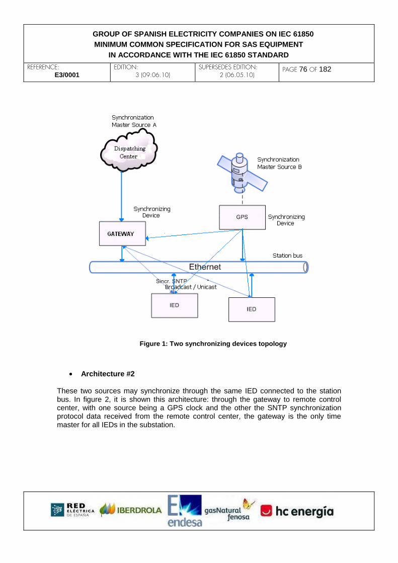
REFERENCE: E3/0001
EDITION: 3 (09.06.10)
SUPERSEDES EDITION: 2 (06.05.10)
PAGE 76 OF 182
GROUP OF SPANISH ELECTRICITY COMPANIES ON IEC 61850
MINIMUM COMMON SPECIFICATION FOR SAS EQUIPMENT
IN ACCORDANCE WITH THE IEC 61850 STANDARD
Figure 1: Two synchronizing devices topology
Architecture #2 These two sources may synchronize through the same IED connected to the station bus. In figure 2, it is shown this architecture: through the gateway to remote control center, with one source being a GPS clock and the other the SNTP synchronization protocol data received from the remote control center, the gateway is the only time master for all IEDs in the substation.

REFERENCE: E3/0001
EDITION: 3 (09.06.10)
SUPERSEDES EDITION: 2 (06.05.10)
PAGE 77 OF 182
GROUP OF SPANISH ELECTRICITY COMPANIES ON IEC 61850
MINIMUM COMMON SPECIFICATION FOR SAS EQUIPMENT
IN ACCORDANCE WITH THE IEC 61850 STANDARD
Figure 2: One synchronizing device topology
Independently of the types of synchronization topologies that are possible based on the two synchronization sources, only one of those two synchronization sources must work as the unique synchronization master source at a time, while the second synchronization source must stay as a stand-by synchronization master source. All IEDs connected to the station bus must be kept always synchronized even in the case the active synchronization master source stops working or a switch between the active synchronization master source and the stand-by synchronization master source occurs.
8.3.2 Synchronizing IEDs within a SAS The synchronization protocol will be SNTP1 and the following indicated services will be used:
1 For any additional information refer to RFC 2030 document

REFERENCE: E3/0001
EDITION: 3 (09.06.10)
SUPERSEDES EDITION: 2 (06.05.10)
PAGE 78 OF 182
GROUP OF SPANISH ELECTRICITY COMPANIES ON IEC 61850
MINIMUM COMMON SPECIFICATION FOR SAS EQUIPMENT
IN ACCORDANCE WITH THE IEC 61850 STANDARD
Client Server
Unicast
Multicast
Broadcast
AnyCast
Table 1 – SNTP services to be used
8.4 IED synchronization functionality
8.4.1 Time synchronization
Any IED must be able to be synchronized from two different synchronization sources.
The total configuration of the SNTP will be modeled by LNs like LTMS and LTIM.
Also, time stamping will be carried out at each bay level for any given IED being part of.
Every signal shall include a quality and a time stamp data (the last, according with the
data structure stated in part 7-2 of the standard). Therefore, the time stamp functionali-
ty shall include quality related information by using the following parameters:
a) ClockFailure. It details an internal error RTC (Real Time Clock) within IED and
hence the IED internal time shall be tagged as probably not valid.
b) ClockNotSynchronized. This bit shall be activated whenever the external syn-
chronization source is not available or the received time for the external synchroni-
zation source figures are ‘not synchronized’ (Leap Indicator = 3).
Both, internal clock precisions and the IED time update frequency (synchronization re-
quest through unicast service) shall have such a value that 1ms precision time stamp-
ing must be guaranteed.
In order to be sure that all IEDs within the substation are synchronized with the same
time, it is asked that every single IED must update its time whenever it receives a
SNTP synchronization message, without considering the Leap Indicator value of that
message. Thus, the internal clock updating process after receiving a SNTP message
shall be performed in a time period no longer than 50 milliseconds.
The SNTP services that the IEDs shall simultaneously bear are indicated in the follow-
ing table:
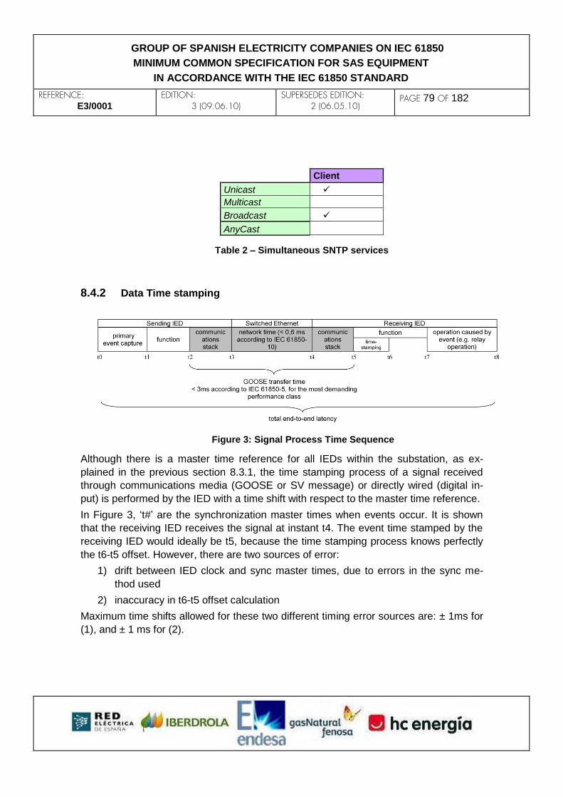
REFERENCE: E3/0001
EDITION: 3 (09.06.10)
SUPERSEDES EDITION: 2 (06.05.10)
PAGE 79 OF 182
GROUP OF SPANISH ELECTRICITY COMPANIES ON IEC 61850
MINIMUM COMMON SPECIFICATION FOR SAS EQUIPMENT
IN ACCORDANCE WITH THE IEC 61850 STANDARD
Client
Unicast
Multicast
Broadcast
AnyCast
Table 2 – Simultaneous SNTP services
8.4.2 Data Time stamping
Figure 3: Signal Process Time Sequence
Although there is a master time reference for all IEDs within the substation, as ex-
plained in the previous section 8.3.1, the time stamping process of a signal received
through communications media (GOOSE or SV message) or directly wired (digital in-
put) is performed by the IED with a time shift with respect to the master time reference.
In Figure 3, ‘t#’ are the synchronization master times when events occur. It is shown
that the receiving IED receives the signal at instant t4. The event time stamped by the
receiving IED would ideally be t5, because the time stamping process knows perfectly
the t6-t5 offset. However, there are two sources of error:
1) drift between IED clock and sync master times, due to errors in the sync me-
thod used
2) inaccuracy in t6-t5 offset calculation
Maximum time shifts allowed for these two different timing error sources are: ± 1ms for
(1), and ± 1 ms for (2).

REFERENCE: E3/0001
EDITION: 3 (09.06.10)
SUPERSEDES EDITION: 2 (06.05.10)
PAGE 80 OF 182
GROUP OF SPANISH ELECTRICITY COMPANIES ON IEC 61850
MINIMUM COMMON SPECIFICATION FOR SAS EQUIPMENT
IN ACCORDANCE WITH THE IEC 61850 STANDARD
9. SECURITY
9.1 Introduction
9.1.1 Foreword to this first version of the chapter With the massive advent of the communications to the SAS and, even more, with the arrival of TCP/IP over Ethernet, cybersecurity is added, with great importance, to the performance requirements set demanded until now. However, two characteristics determine this subject: firstly, utilities (at least, E3-group members) have the problem of the lack of previous solid experience in this issue, and, on the other hand, the communication networks, the devices within and the functionality developed, make this system singular and very different from others where security measures are well installed and proved. These characteristics imply that this chapter is under development with forecast of future updates, and it must be considered as a first approach.
9.1.2 Objectives The main objectives of the current chapter are to study the information security for the secondary systems operation in 61850 substations and to decide the most proper solutions in order to minimize the risks with a reasonable investment.
9.1.3 Overview The first block (sections 9.2 to 9.4) shows the most probable cyber-attacks. Firstly, a set of the most common threats and possible attacks, in general terms, are listed. Next, the communication scheme is explained, identifying the types of communicaction inside the substation. Finally, the most expected attacks are listed and described taking into account some hypothesis explained as well. In the second block (sections 9.5 and 9.6), minimum security requirements are shown and required behaviour under each attack is established. Finally, section 9.6 shows the countermeasures and their relationship to each type of communication. The referenced document for the whole chapter is the standard IEC-62351 (mainly in its parts 62351-1, 62351-2, 62351-3, 62351-4 and 62351-6).

REFERENCE: E3/0001
EDITION: 3 (09.06.10)
SUPERSEDES EDITION: 2 (06.05.10)
PAGE 81 OF 182
GROUP OF SPANISH ELECTRICITY COMPANIES ON IEC 61850
MINIMUM COMMON SPECIFICATION FOR SAS EQUIPMENT
IN ACCORDANCE WITH THE IEC 61850 STANDARD
9.2 Threats and attacks There are a lot of threats and possible attacks which may trigger non-desirable consequences. For example, the IEC-62351 standard, in part 1, shows a classification of general causes:
Inadvertent causes: safety failures, equipment failures, carelessness…
Deliberate causes: disgruntled employee, industrial espionage, vandalism, cyber hackers...
These threats may trigger an attack over the system or a part of it. Paying attention to the nature of the action, a possible classification could be the next one:
Attack for listening: eavesdropping, traffic analysis, EM/RF interception, indiscretions by personnel, etc.
Interactions with the system: masquerade, bypassing controls, authorization violation, physical intrusion, man-in-the-middle, integrity violation, theft, replay, etc.
Planted in system: virus/worms, Trojan horse, trapdoor, service spoofing, etc.
Attacks that deny the service: resource exhaustion, equipment failure, software failure, etc.
Threats after-the-fact: denial of action, claim of action, stolen/altered, repudiation, etc.
Whatever the cause or the type of the attack could be, the main objective of a security system is to avoid the success of any attack or, at least, minimize the consequences of a successful attack. Total security for each one of the attack consequences is unworkable, due to the high complexity of the subject. It will be necessary to identify those points where it is interesting the investment of a reasonable amount of time and money. Furthermore, it is absolutely necessary to balance the security measures and complexity of maintenance and exploitation.
9.3 Communication scheme The communications scheme can be divided into four well-defined cases:
Communications inside the substation or through the LAN (or LANs)

REFERENCE: E3/0001
EDITION: 3 (09.06.10)
SUPERSEDES EDITION: 2 (06.05.10)
PAGE 82 OF 182
GROUP OF SPANISH ELECTRICITY COMPANIES ON IEC 61850
MINIMUM COMMON SPECIFICATION FOR SAS EQUIPMENT
IN ACCORDANCE WITH THE IEC 61850 STANDARD
Communications between substations
Communications between substations and control centers
Communications between substations and remote configuration and monitoring agents
Each case has its own characteristics that make their weaknesses and strengths be different and, therefore, threats and possible attacks are not similar. Nowadays, only the communications inside the substation are provided by the IEC 61850 although communications outside the substation are expected to be analyzed in the future due to substitute proprietary protocols and other standard protocols like the IEC 60870-5 series or DNP 3.0. For these reasons, communications inside substations shall be studied in this document, admitting the future possibility of implementing IEC 61850 outside substation communications.
9.3.1 Communications inside the substation Chapter 5 of this document shows two possible LAN topologies for the bus station. In both topologies, the last device in the link to the control center, is the substation gateway to remote control center. The communication inside the substation is developed from this IED to the last IEDs in the lowest level (IEDs in level 0). The next graphics show the two topologies and, in both of them, the existence of the Gateway as the link with the control center.
As explained in previous chapters, there could be three different kinds of information

REFERENCE: E3/0001
EDITION: 3 (09.06.10)
SUPERSEDES EDITION: 2 (06.05.10)
PAGE 83 OF 182
GROUP OF SPANISH ELECTRICITY COMPANIES ON IEC 61850
MINIMUM COMMON SPECIFICATION FOR SAS EQUIPMENT
IN ACCORDANCE WITH THE IEC 61850 STANDARD
exchanging inside the substation through the station bus:
Communication for specifically protection functions which will be conducted through GOOSE messages. In this case, because of the criticality, reliability and speed are crucial.
Communication for not critical functions such as reporting, logging, commands, etc. where the quality and the amount of data take precedence over speed, will be conducted through MMS communication. Communication for maintenance and diagnosis operations over ACSI services, such as GetDataValues, SetDataValues, polling actions and so on, is included in this type.
File transfer such as SCL files or report fault files.
9.4 Expected attacks Some hypothesis and postulates have been taken into account in order to identify the most likely attacks presented in this section:
A. The substation-LAN, or LANs, normally will be connected to the private network
of the utility. So it is strictly isolated from the Internet. One or several links with
Internet is another possibility for explotation and maintenance but, then, the
system is ‘open’ to non-desirable users.
B. If someone may go into the substation with malicious purposes, avoiding the
physical security measures, a direct attack over the equipment, primary or sec-
ondary system, will be more probable than a cyber attack. This person could
make a lot of damages e.g. switching off several control and protection devices
or damaging physically any device. Those examples are less complicated than
connecting to the substation-LAN through the station switch with a PC and
causing a non-desirable consequence.
Outside substation cyber-attacks have to be avoided mainly by firewalls and access controls implemented in the software applications over the company´s Intranet. These security measures are out of the scope of IEC 61850 and, therefore, will not be discussed in this document. However, they are considered a fundamental part of a security system for this kind of installations. If it is not considered that anybody may go physically into the substation and provoke a cyber attack (at least not as a priority threat), then the cyber attacks, made inside the substation, may be caused by carelessness of the employees or by disgruntled workers, with authorized access and malicious purposes. The most likely attacks are listed in the next sections.

REFERENCE: E3/0001
EDITION: 3 (09.06.10)
SUPERSEDES EDITION: 2 (06.05.10)
PAGE 84 OF 182
GROUP OF SPANISH ELECTRICITY COMPANIES ON IEC 61850
MINIMUM COMMON SPECIFICATION FOR SAS EQUIPMENT
IN ACCORDANCE WITH THE IEC 61850 STANDARD
9.4.1 Repudiation The consequences of this attack are either the denial, by an entity, of an action in which it was involved, or the claim of an action in which it was not involved. For example, claim to have sent to a receiver, at a specified time, information that was not sent, or was sent at a different time.
9.4.2 Denial of service It inhibits the normal use or management of communications facilities. Different forms of service denial exist, for example, the disruption of the LAN, directly disabling the network. 9.4.2.1 Resource exhaustion
It is a ‘denial of service’ attack. An entity could make fast connections and disconnections or make massive connections to a server. These actions would cause the IED to slow down and finally would cause the communications to break between server and clients. The same result would appear if the network were overloaded with messages.
9.4.3 Masquerade It takes place when one entity pretends to be a different entitiy in order to originate fraudulent information, modify legitimate information, use fraudulent identity to gain unauthorized access or authorize fraudulent transactions or endorse them. A masquerade attack usually includes one of other forms of attacks, for example, replay or denial of service. Nevertheless, inadvertent causes may provoke this attack, for example if an IED takes a wrong IP direction as a consequence of a software or file configuration failure, it might cause that other IEDs could not identify it correctly. 9.4.3.1 Man-in-the-middle
It is a type of masquerade attack. The attacker makes independent connections

REFERENCE: E3/0001
EDITION: 3 (09.06.10)
SUPERSEDES EDITION: 2 (06.05.10)
PAGE 85 OF 182
GROUP OF SPANISH ELECTRICITY COMPANIES ON IEC 61850
MINIMUM COMMON SPECIFICATION FOR SAS EQUIPMENT
IN ACCORDANCE WITH THE IEC 61850 STANDARD
between two entities so that it receives the messages from the original source and it sends messages to the original destination introducing a time delay, modificating the information or both of them.
9.4.4 Eavesdropping Also known as monitoring, the objective is to obtain information that is being transmitted. It is the main cause of confidentiality loss. Two eavesdropping modes have been identified:
Attack caused by an authorized entity
IEDs and the company´s employees are authorized entities. The first entity is discarded as a cause of eavesdropping. It is unlikely that an IED, e.g. protection device, has been modified by the ciber-attackers in order to store information which will be sent and used later. On the other hand, an employee might be the cause of eavesdropping. Probably, the fact that an employee accesses non-authorized information will be unintentional, but could provoke other incorrect actions because of misunderstanding.
Attack caused by an unauthorized entity
As it was said before, inside-the-substation attacks are not considered so an hypothetic eavesdropping has to be provoked by an external agent. For example, spying.
9.4.5 Replay It involves the passive capture of a data unit and its subsequent retransmission to produce an unauthorized effect. It will use previously transmitted messages. It could be a masquerade based attack but not necessarily.
9.4.6 Non-desirable-CID loading. It could be an error or done on purpose. A non-desirable-CID means a wrong configuration file, e.g. it is a correct file but an earlier version. Several cases of integrity loss are identified:

REFERENCE: E3/0001
EDITION: 3 (09.06.10)
SUPERSEDES EDITION: 2 (06.05.10)
PAGE 86 OF 182
GROUP OF SPANISH ELECTRICITY COMPANIES ON IEC 61850
MINIMUM COMMON SPECIFICATION FOR SAS EQUIPMENT
IN ACCORDANCE WITH THE IEC 61850 STANDARD
Introducing an USB, that contains a CID file without knowledge of the employee, in order to recover the log file.
Loading of an earlier version CID
Loading of a CID corresponding to another IED.
9.4.7 Malicious code Virus, worms and Trojan horses introduced into the devices through USB connection, FTP or externally via the LAN Network.
9.5 Security assessments – requirements The security requirements involve to avoid the consequences of an attack to the system. To sum up, the next provisions apply:
Confidentiality: preventing the unauthorized acces to information.
Integrity: preventing the unauthorized modification or theft of information.
Availability: preventing the denial of service and ensuring authorized acces to information.
Non-repudiation or accountability: preventing the denial of an action that took place or the claim of an action that did not take place.
Authentication: assuring that a communication and the transmitted information is authentic, i.e. the message is from the source that it claims to be from.
The next table shows practice cases in which it is generated a loss of any of the above requirements.
Requirements Key:
Attacks (1) (2) (3) (4) (5) (1) Confidentiality
Repudiation X (2) Integrity
Denial of service X (3) Availability
Resource exhaustion X (4) Non-repudiation or accountability
Masquerade X X X X X (5)Authentication
Man-in-the-middle X X
Eavesdropping X
Replay X
Non-desirable-CID loading
X X X
Malicious code X X X X X
REFERENCE: E3/0001
EDITION: 3 (09.06.10)
SUPERSEDES EDITION: 2 (06.05.10)
PAGE 87 OF 182
GROUP OF SPANISH ELECTRICITY COMPANIES ON IEC 61850
MINIMUM COMMON SPECIFICATION FOR SAS EQUIPMENT
IN ACCORDANCE WITH THE IEC 61850 STANDARD
The consequences of a virus, Trojan horse or any other type of malicious code successfully introduced in a device, might cause the loss of any of the above requirements. A masquerade attack, as it was said before, might imply one of the other forms of attacks. In following sections, the behaviour of the required system security against the early defined attacks is analyzed. The system will fullfil the desired behaviours depending on the security measures implemented. The situation in which one or several attacks do not have associated countermeasures is included.
9.5.1 Required behaviour
Repudiation. The requirement is the accomplishment of the two next rules:
o No agent, which has done an action, shall deny the responsibility later.
o No agent, which has not performed an action, shall claim the responsi-
bility later
Denial of service: A normal situation shall require a minimum time availability. In case of attack, it could be required any of the next behaviours:
o Devices time availability is kept.
o Devices time availability is decreased till a certain level.
o No time availiability is required under a denial of service attack.
Resource exhaustion. The highest desired level would imply to avoid the device saturation and, therefore, the device crash. The next option would be determining a period of time in which the device must reject the attack. The last level, which is the lowest one, minimizes the consequences of isolating some parts of the device, mainly those that suffer the attack.
Man in the middle. The most desirable situation is that this attack does not succeed. If the achievement of the attack is inevitable, the second requirement is minimize the time delay the agent introduces and in a third stage, no device must accept as valid the adulterated information received as a consequence of a Man-in-the-middle attack.
Eavesdropping. The required behaviour is the absolute avoidance of information access by non-authorized employees and the total avoidance of attacks caused by unauthorized entities.
Replay. The desirable behaviour shall be that no external agent could be able to launch the attack. If the achievement of the attack is inevitable, no device must accept as valid the adulterated information received as a consequence of the replay.
Non-desirable-CID loading. In all cases the objective is to avoid the non-

REFERENCE: E3/0001
EDITION: 3 (09.06.10)
SUPERSEDES EDITION: 2 (06.05.10)
PAGE 88 OF 182
GROUP OF SPANISH ELECTRICITY COMPANIES ON IEC 61850
MINIMUM COMMON SPECIFICATION FOR SAS EQUIPMENT
IN ACCORDANCE WITH THE IEC 61850 STANDARD
desirable-CID loading. As a second option, at least it shall be mandatory to know the author and date of the loading.
Malicious code. The required level is to achieve the 0% of infection. As it was said before, if devices are connected to an isolate-substation-LAN, there will be no means to get a virus into the system. The only ways will be the USB and the FTP connection. In both cases 0% infection shall be required. In the case of the USB, if 0% infection cannot be guaranteed, at least it shall be necessary to know the author and the time stamp of the malicious loading.
9.6 Security methods In the following sections, security methods are explained.
9.6.1 Encryption This countermeasure is not required due to the hypothesis A and B showed in section 9.4. In addition, operation, performance and maintenance problems associated with this measure have been described.
9.6.2 Digital signature This countermeasure is not required due to the hypothesis A and B showed in section 9.4. In addition, operation and maintenance problems associated with this measure have to be taken into account, i.e. digital certificates revocation or update and certification authorities management.
9.6.3 Association with Authentication 9.6.3.1 MMS Authentication
Authentication for MMS associations will be supported as explained in 61850-7-2, section 7.4. This section defines two attributes within the class: ‘AssociationId’ and ‘AuthenticationParameter’. It is said that the type of these attributes is SCSM specific so is addressed to part 8-1 of the standard. The association mapping to MMS protocol is explained in 61850-8-1, section 10.2. simply referring to ISO 9506 and to the works under development of 7 and 15 WG of

REFERENCE: E3/0001
EDITION: 3 (09.06.10)
SUPERSEDES EDITION: 2 (06.05.10)
PAGE 89 OF 182
GROUP OF SPANISH ELECTRICITY COMPANIES ON IEC 61850
MINIMUM COMMON SPECIFICATION FOR SAS EQUIPMENT
IN ACCORDANCE WITH THE IEC 61850 STANDARD
TC 57. The WG 15 is the developer of IEC 62351 standard. Both ISO 9506 and IEC 62351 make reference to the Association Control Service Element (ACSE)2 as the security method for association authentication. The Access Condition (ISO 9506) type, which is the MMS element on which ‘AuthenticationParameter’ attribute is mapped to, shall be ‘Password’ as defined in ISO 9506-1, section 9.1.2. The ‘virtual access view’ concept associated to MMS authentication is not considered nowadays but it will be followed up by the E3 group.
9.6.4 Audit/Logging Each IED shall register, in the internal event log file defined in 6.4.4, the following events:
MMS associations initialized successfully.
MMS associations rejected (by authentication or parameter negotiation).
MMS associations aborted or cancelled.
FTP connections initialized successfully.
FTP connection rejected.
File loadings and downloadings through the USB port in addition to the text file defined in section 6.2.4.
For security monitoring, the LN GSAL will be used in the IED.
9.6.5 Access control for remote configuration and monitoring agents This countermeasure is not required due to the hypothesis A and B showed in section 9.4. However, each configuration, management or maintenance tool shall be provided with access control security, but this is a utility issue.
9.6.6 Security over switches Switches shall be able to address their ports by IP addresses in addition to MAC addresses and shall be able to limit the throughput over each port.
2 The ACSE protocol is defined in ISO 8650 and ISO 8649 and ITU X.217 X.227 and X.237.

REFERENCE: E3/0001
EDITION: 3 (09.06.10)
SUPERSEDES EDITION: 2 (06.05.10)
PAGE 90 OF 182
GROUP OF SPANISH ELECTRICITY COMPANIES ON IEC 61850
MINIMUM COMMON SPECIFICATION FOR SAS EQUIPMENT
IN ACCORDANCE WITH THE IEC 61850 STANDARD
The way to configure the switches in order to achieve a certain security level is a utility issue.
9.6.7 Anti-virus The devices, which might be infected by malicious code, must allow the installation of anti-virus software. The installation and the anti-virus operation will not disturb the IED performance and functionality.
9.7 Application of countermeasures The next clauses show the application, over each type of communication, of the different security measures explained above.
9.7.1 Security general methods Security general methods mean those countermeasures which are not associated di-rectly to any communication profile.
Access control as explained in section 9.6.5.
IP addressing taking into account section 9.6.6.
9.7.2 Security methods for MMS The following countermeasures, specified above, are required:
Authentication, User/Password as explained in section 9.6.3.
Audit/Logging as explained in section 9.6.4.
9.7.3 Security methods for GOOSE No additional countermeasures to the GOOSE validation mechanism explained in section 7.1.3. are required, due to the criticality (transfer time) associated to GOOSE communication and the hypothesis A and B showed in section 9.4.

REFERENCE: E3/0001
EDITION: 3 (09.06.10)
SUPERSEDES EDITION: 2 (06.05.10)
PAGE 91 OF 182
GROUP OF SPANISH ELECTRICITY COMPANIES ON IEC 61850
MINIMUM COMMON SPECIFICATION FOR SAS EQUIPMENT
IN ACCORDANCE WITH THE IEC 61850 STANDARD
9.7.4 Security methods for SCL digital signature These countermeasures are not required because of the hypothesis A and B showed in section 9.4.
9.7.5 Security for FTP No additional security countermeasures are required because of the hypothesis A and B showed in section 9.4, except Audit/Loging explained in section 9.6.4. Nevertheless, any enhanced security over FTP such as SFTP, FTP over SSH, or FTP over SSL, will be considered in future revisions.
9.7.6 Security for USB The required security countermeasures associated to the USB communication are the following:
IED behaviour described in sections 6.2.2 to 6.2.4 and 6.2.6.
Non-desired CID loadings can be avoided combining the loading modes with the activation processes. The security levels achieved are explained in the next table: in the first column, the two types of loading mode are listed and in the first row, the two types of activation processes. The cells in the crosses show the security behaviour.
AUTOMATIC CONTROLLED
INDIFERENT Security does not exist CID validated but not activated
PROTECTED MODE Safe: CID is not loaded3 Safe: CID is not loaded3
Anti-virus considerations made in section 9.6.7
3 In these cases, the CID loading will be made changing to upload mode by mean of a physical interface
so that the subsequent CID loading would be desired.

REFERENCE: E3/0001
EDITION: 3 (09.06.10)
SUPERSEDES EDITION: 2 (06.05.10)
PAGE 92 OF 182
GROUP OF SPANISH ELECTRICITY COMPANIES ON IEC 61850
MINIMUM COMMON SPECIFICATION FOR SAS EQUIPMENT
IN ACCORDANCE WITH THE IEC 61850 STANDARD
9.8 Security management Under consideration. To be developed in future revisions.

REFERENCE: E3/0001
EDITION: 3 (09.06.10)
SUPERSEDES EDITION: 2 (06.05.10)
PAGE 93 OF 182
GROUP OF SPANISH ELECTRICITY COMPANIES ON IEC 61850
MINIMUM COMMON SPECIFICATION FOR SAS EQUIPMENT
IN ACCORDANCE WITH THE IEC 61850 STANDARD
10. PROCESS BUS
10.1 Summary Process level functions are normally based on the GOOSE (IEC 61850-8-1) and the SV (IEC 61850-9-2) protocols. The two key requisites for them are reliability and performance. A separate analysis for each protocol is provided, including recommendations for the communication links and the switch layout. Regarding the acquisition and delivery of sampled analog magnitudes (by means of the SV protocol), and with a view to guarantee minimum serial complexity and thus maximum reliability, only 2-tier architectures shall be considered, i.e. those where
i) the SV-source IED acquires its input information in the form of an analog magnitude directly from the physical world, and
ii) the SV samples travel from the source IED to the sink IED without any intermediate IED in-between, except possibly one or more Ethernet switches.
The first of the above conditions allows the SV-source IED to be any kind of sensor, such as a non-conventional instrument transformer or an electronic device with analog inputs directly wired from a conventional instrument transformer, as long as its output is SV-coded. The data model of an SV-source IED and the structure of the dataset containing the samples shall be as specified in the ‘Implementation Guideline for Digital Interface to Instrument Transformers using IEC 61850-9-2’, frequently referred to as ‘IEC 61850-9-2 Lite Edition’. In principle, the requirements of time coherence between different SV-source IEDs shall be at least those declared in ‘IEC 61850-9-2 Lite Edition’). This implies:
Limited delay or fixed delay methods are not accepted.
The synchronization messages shall have an accuracy of ± 1 microsecond or better (at the origin).
Sampling IEDs will be kept synchronized by
a server (which can be the SV client itself) that sends one synchronization pulse per second (1PPS), or
a method able to provide a still higher accuracy (e.g. IEEE 1588 or IRIG-B).
REFERENCE: E3/0001
EDITION: 3 (09.06.10)
SUPERSEDES EDITION: 2 (06.05.10)
PAGE 94 OF 182
GROUP OF SPANISH ELECTRICITY COMPANIES ON IEC 61850
MINIMUM COMMON SPECIFICATION FOR SAS EQUIPMENT
IN ACCORDANCE WITH THE IEC 61850 STANDARD
The possible process bus architectures are almost countless, given the high number of independent choices. Nevertheless, a few reasonable architectures are suggested, ranging from bottom to top in terms of cost: a virtual process bus hosted within the station bus, a non-redundant point-to-point architecture and a full process bus with maximum redundancy.
10.2 Introduction Process level functions, as defined in IEC 61850-2 (Glossary), are the logical interfaces 4 (CT and VT instantaneous data exchange, especially samples, between level 0 and level 1) and 5 (low-latency control-data exchange between level 0 and level 1). The logical interfaces are defined in clause 6.2 of IEC 61850-1 (Introduction and overview). The SCSMs (specific mappings) currently specified by the standard are the GOOSE protocol for logical interface 5 (described in IEC 61850-8-1) and the SV protocol for logical interface 4 (described in IEC 61850-9-1 and 2). ‘Process bus’ is a network dedicated to the communications pertaining to process level functions and perhaps also those confined within level 1, i.e. logical interface 3 (level-1-to-level-1 or level-1-to-level-0 data exchange within a bay) and logical interface 8 (level-1-to-level-1 direct data exchange between the bays, especially for fast functions such as interlocking). An immediate consequence from the above definition is that the process bus, when present, must encompass the levels 0 and 1, and exclude level 2 and above. The existence of a process bus is not mandatory; an installation may choose to transmit the process level communications over the station bus, along with those pertaining to other logical interfaces (such as client/server communications involving level 2). In that case, the station bus would reach the three levels within the substation, including level 0. If a process bus is present, all level 1 IEDs will be typically attached to both the station and the process bus, whereas the level 0 IEDs will be typically attached to the process bus only, in which case the supervisory and control functions performed from level 2 on the level 0 IEDs, if they exist, shall take place through a level 1 IED acting as a proxy. An approach that is intermediate between the presence of a physical process bus, i.e. a network physically isolated from the station bus, and the use of a single network (which shall still be called the station bus) for all logical interfaces inside the substation, is the implementation of a ‘virtual process bus’ by means of a software mechanism such as Ethernet VLANs. The main reason for implementing a process bus is assuring the performance (especially in terms of latency) of logical interfaces 4, 5 and 8, by
i. preventing critical data traffic from contending with client/server data traffic. ii. allocating special and specific resources, both hardware and software, for
critical data traffic, so as to optimize latency and reliability.
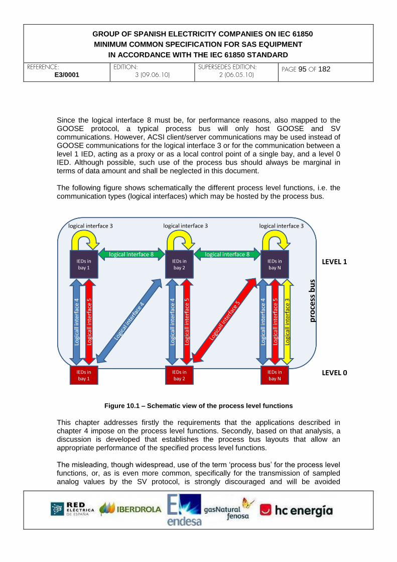
REFERENCE: E3/0001
EDITION: 3 (09.06.10)
SUPERSEDES EDITION: 2 (06.05.10)
PAGE 95 OF 182
GROUP OF SPANISH ELECTRICITY COMPANIES ON IEC 61850
MINIMUM COMMON SPECIFICATION FOR SAS EQUIPMENT
IN ACCORDANCE WITH THE IEC 61850 STANDARD
Since the logical interface 8 must be, for performance reasons, also mapped to the GOOSE protocol, a typical process bus will only host GOOSE and SV communications. However, ACSI client/server communications may be used instead of GOOSE communications for the logical interface 3 or for the communication between a level 1 IED, acting as a proxy or as a local control point of a single bay, and a level 0 IED. Although possible, such use of the process bus should always be marginal in terms of data amount and shall be neglected in this document. The following figure shows schematically the different process level functions, i.e. the communication types (logical interfaces) which may be hosted by the process bus.
Figure 10.1 – Schematic view of the process level functions
This chapter addresses firstly the requirements that the applications described in chapter 4 impose on the process level functions. Secondly, based on that analysis, a discussion is developed that establishes the process bus layouts that allow an appropriate performance of the specified process level functions. The misleading, though widespread, use of the term ‘process bus’ for the process level functions, or, as is even more common, specifically for the transmission of sampled analog values by the SV protocol, is strongly discouraged and will be avoided
REFERENCE: E3/0001
EDITION: 3 (09.06.10)
SUPERSEDES EDITION: 2 (06.05.10)
PAGE 96 OF 182
GROUP OF SPANISH ELECTRICITY COMPANIES ON IEC 61850
MINIMUM COMMON SPECIFICATION FOR SAS EQUIPMENT
IN ACCORDANCE WITH THE IEC 61850 STANDARD
throughout this document.
10.3 General requirements of process level functions This section analyses the nature and requirements that are common to the logical interfaces 5 and 8 (GOOSE-mapped process level functions) and 4 (SV-mapped process level functions). A specific analysis of each of them is to be found in later sections. The main challenge of process level functions is availability. The nature of such functions implies that poor performance may have the same consequences as the total failure of a component. Therefore, reliability and performance are the crucial issues and will be treated separately in the following sections.
10.3.1 Reliability IEC-61850-communicated process level functions entail the deployment of electronic devices close to the process, i.e. in places where no such devices have usually existed so far and the operation was the responsibility of robust and long-proven equipment. There is clearly a potential reduction in reliability when conventionally-wired process level communications are replaced by an IEC 61850 system. 10.3.1.1 Serial versus parallel complexity
Serial complexity can be defined as the number of components an item of information must traverse from its origin to its destination. Serial complexity diminishes reliability and thus shall be reduced to a minimum. However, IEC-61850-communicated process level functions between level-1 and level-0 IEDs inherently impose a higher degree of serial complexity than conventional wired communications, because of the addition of the Ethernet network and the level-0 devices. This is an absolute drawback of IEC 61850 process level functions that can only be countered by
i) Robust design and manufacture of the added components (low MTBF, low MTTR)
ii) Redundancy of the added components
Apart from this unavoidable degree of serial complexity, further serial complexity shall only be implemented if it provides compensating benefits that cannot be achieved otherwise. An example is a multi-tier switch architecture, i.e. one where a message must go through more than one Ethernet switch. Another example is the use of ‘nested merging units’ for the transmission of analog information. This issue will be further

REFERENCE: E3/0001
EDITION: 3 (09.06.10)
SUPERSEDES EDITION: 2 (06.05.10)
PAGE 97 OF 182
GROUP OF SPANISH ELECTRICITY COMPANIES ON IEC 61850
MINIMUM COMMON SPECIFICATION FOR SAS EQUIPMENT
IN ACCORDANCE WITH THE IEC 61850 STANDARD
discussed in the section devoted to SV-mapped process level functions. Parallel complexity can be defined as the number of alternative paths available for an item of information to go from its origin to its destination. Parallel complexity is a way to achieve redundancy when combined with appropriate redundancy protocols. The following section examines this particular more closely. 10.3.1.2 Redundancy in IEC 61850 versus conventional substations
Redundancy already exists in conventional substations where the concept of ‘overlapping protection zones’ is used, so that a fault on the power network can be cleared (with probably lower selectivity and/or a longer response time) by a backup IED, in case the primary IED fails. IEC-61850-communicated process level functions should never encumber this zonal redundancy. Consider for instance an Ethernet switch that connects all the voltage and current sensors and all the protection IEDs related to a busbar. A failure of such switch would prevent, should a fault occur, the operation of the primary protection IED (that which is closest to the fault) as well as the operation of the backup protection IED. Consequently, either switch redundancy or physical LAN segmentation is mandatory. On the other hand, the design of many conventional substations does not introduce redundancy in all components. In the previous example, a line bay could be protected by an overcurrent/overvoltage IED alone, connected to non-redundant current and voltage measurement circuits. The aim of IEC 61850 engineering does not need to be the achievement of a higher degree of redundancy. In other words, non-redundant Ethernet switches or single point-to-point Ethernet connections may constitute an acceptable solution in such a case. 10.3.1.3 Level-0 IED redundancy
The failure of a single level-0 IED may cause, depending on the functions performed thereby, the following types of serious disruption:
Inability to operate a power network interrupting element and to sense its status.
Inability to process analog measurements, which implies inability for one or more protection IEDs to clear a fault in the power network.
Although doubling level-0 IEDs is a way to improve reliability, taking real advantage of it is not immediate. The following considerations apply:
Commands might have to be doubled, i.e. sent to both level-0 IEDs
REFERENCE: E3/0001
EDITION: 3 (09.06.10)
SUPERSEDES EDITION: 2 (06.05.10)
PAGE 98 OF 182
GROUP OF SPANISH ELECTRICITY COMPANIES ON IEC 61850
MINIMUM COMMON SPECIFICATION FOR SAS EQUIPMENT
IN ACCORDANCE WITH THE IEC 61850 STANDARD
simultaneously.
An IED which receives one SV stream from each level-0 IED (assuming they are time-coherent) must either
i) discard one (typically the latest) of each pair of homologous samples, or
ii) optionally, check for the equality of the two homologous samples, and set an exception status if they are not equal
An IED which receives status signalling must consider all signals as if coming from the same level-0 IED, i.e. the most recent signal is the valid one.
10.3.1.4 Network redundancy
Network redundancy is one of the subjects of the yet expected IEC 61850-90-4 Technical Report, on ‘Network Engineering Guidelines’, which will be partly based on IEC 62439 (‘Highly Available Automation Networks’). The E3 Group will pay due attention to these IEC outputs when they are released. First-rate installations will demand zero recovery time upon a single failure, which is only achievable through the so-called ‘seamless network redundancy’. However, a more economic alternative may well found its place in less critical systems. In that respect, a non-redundant network seems to be a coherent match for non-redundant level-0 IEDs. A brief exposition follows on the different possibilities for network redundancy. Seamless network redundancy
Seamless network redundancy consists in having every frame sent through independent network paths, so that a single failure cannot prevent the ‘lucky’ frame to reach its destination with no added delay. The redundancy should be handled in the link layer, so that the higher layers do not need to be doubled. Two protocols are considered at the moment: PRP (Parallel Redundant Protocol), which was mentioned in chapter 5 of the present document, and HSR (High-availability Seamless Ring), which is a ring based on the same double-delivery principle as PRP. The following layouts can be evaluated:
Redundant point-to-point Ethernet connections. From the network point of view, it is arguably the best solution in terms of both reliability and performance. It has, however, two disadvantages:
i) it is less scalable than a switched network
ii) at every IED, as many pairs of Ethernet ports are required as connected

REFERENCE: E3/0001
EDITION: 3 (09.06.10)
SUPERSEDES EDITION: 2 (06.05.10)
PAGE 99 OF 182
GROUP OF SPANISH ELECTRICITY COMPANIES ON IEC 61850
MINIMUM COMMON SPECIFICATION FOR SAS EQUIPMENT
IN ACCORDANCE WITH THE IEC 61850 STANDARD
IEDs
A one-tier PRP process bus, i.e. a double star where all frames must traverse one switch only. It provides the best balance between reliability, performance, scalability and cost-effectiveness. However, a practical limit to this solution is the maximum number of ports per switch.
A multi-tier PRP process bus, where frames must traverse two or more switches. This provides almost maximum reliability but higher latencies. A variant of this architecture is a PRP+RSTP double ring, where the two independent LANs have each a physical ring topology, and at any given moment one of the inter-switch links is an RSTP-managed backup which will become effective only if another link fails.
An HSR process bus, with almost maximum reliability and still higher latencies than multi-tier PRP. It can be expected to be more economical than PRP because it eliminates the external Ethernet switches.
Alternatives to seamless network redundancy
It is sometimes stated that an IEC 61850 process bus must offer seamless redundancy. However, this is not exactly true, as was shown in 10.3.1.2. In applications where single-element failure is allowed nowadays, a transition to IEC 61850 could be carried out without a demand for a higher level of redundancy. In that respect, the following layouts can be acceptable, depending on the reliability standards imposed for the whole system and the assessment of the individual reliability (MTBF and MTTR) of the level-0 IEDs and the network:
Switched Ethernet with RSTP (Rapid Spanning Tree Protocol) redundancy
Single point-to-point Ethernet connections
Switched Ethernet without redundancy (e.g. a non-redundant star)
In the second and the third of the above layouts, the mean recovery time amounts to the MMTR of the failed component, whilst a solution based on RSTP can be expected to have a recovery time of several seconds. Therefore, when there is no seamless network redundancy, latency-critical functions shall rely on backup protection rather than network redundancy.
10.3.2 Performance With respect to performance, messaging speed is critical in process level functions and both the GOOSE and the SV protocols have been designed upon this requirement. The following two sections discuss two concepts that are inter-related and crucial to

REFERENCE: E3/0001
EDITION: 3 (09.06.10)
SUPERSEDES EDITION: 2 (06.05.10)
PAGE 100 OF 182
GROUP OF SPANISH ELECTRICITY COMPANIES ON IEC 61850
MINIMUM COMMON SPECIFICATION FOR SAS EQUIPMENT
IN ACCORDANCE WITH THE IEC 61850 STANDARD
process level performance: transfer time and the choice between unicast and multicast messaging. 10.3.2.1 Transfer time and its components The transfer time of a message is defined in IEC 61850-5 as that required for ‘the complete transmission of a message including necessary handling at both ends’. The transfer time is then: Transfer time = (handling time at sending IED) + (network time) + (handling time at receiving IED)
A discussion follows about the different factors that add to the transfer time and the possible ways to reduce their impact. The IED handling time is the time needed by an IED’s communications software before/after the message begins/ends to be ‘put/get on/from the wire’. At the sending IED, it is the time elapsed from the instant when the communicating function leaves the message (an Ethernet APDU) at the place from which the Ethernet firmware will pick it up, until the moment when the first bit of the resulting Ethernet frame is ‘put on the wire’. At the receiving IED, it is the time elapsed from the instant when the last bit of the Ethernet frame is ‘got from the wire’ until the instant when the Ethernet firmware leaves the APDU at the place from which the communicating function will pick it up. It must be noticed that any queueing at the access to/from the Ethernet firmware (for instance if many applications want to use the Ethernet port at the same time) adds to the IED handling time. Both IED handling times (at origin and destination) are independent from the nature and current throughput of the LAN. Assuming that the frame must traverse N Ethernet switches (thus taking N+1 ‘hops’) from the sending to the receiving IED, the network time shall be the sum of:
i) The ‘frame time’ (i.e. the frame size divided by the bit rate of the network interface cards) multiplied by the number of ‘hops’, plus
ii) The sum of all the ‘switch latencies’ (i.e. the time required by the switches to process the frame internally)
Henceforth, the first of the above addends shall be called ‘accumulated frame time’, and the second shall be called ‘accumulated switch latency’. Note 1: It is assumed that the switches work in a ‘store and forward’ fashion, which means that the frame is completely ‘read’ from the input port, then processed, and

REFERENCE: E3/0001
EDITION: 3 (09.06.10)
SUPERSEDES EDITION: 2 (06.05.10)
PAGE 101 OF 182
GROUP OF SPANISH ELECTRICITY COMPANIES ON IEC 61850
MINIMUM COMMON SPECIFICATION FOR SAS EQUIPMENT
IN ACCORDANCE WITH THE IEC 61850 STANDARD
finally ‘written’ on the output port. Note 2: In a LAN, the ‘wire’ latencies are within the nanosecond range and thus negligible. Note 3: The first ‘frame time’ takes place at the sending IED; however, it is computed within the network time. The frame time at a receiving device is synchronous (because the ‘wire’ latency is negligible) with respect to that at the immediate sending device; therefore, it is not computed. The network time is independent from the nature and current throughput of both the sending and the receiving IED. More particularly, the individual frame time depends only on the frame size and the network bit rate, and is independent from the nature and current throughput of the switches. Conversely, the switch latency depends only on the nature and current throughput of the switch, and is practically independent from the frame size and the network bit rate. The following figure shows schematically the structure of the transfer time.
Figure 10.2 – Structure of the transfer time
The above dissection allows us to pinpoint the causes of normal and excessive transfer time. The following principles must always be borne in mind:

REFERENCE: E3/0001
EDITION: 3 (09.06.10)
SUPERSEDES EDITION: 2 (06.05.10)
PAGE 102 OF 182
GROUP OF SPANISH ELECTRICITY COMPANIES ON IEC 61850
MINIMUM COMMON SPECIFICATION FOR SAS EQUIPMENT
IN ACCORDANCE WITH THE IEC 61850 STANDARD
The IED handling time depends on the IED’s hardware and software design and the operation of its software at a particular moment. It is almost impossible to measure, although it can be estimated (see IEC 61850-10, clause 7.2).
Excessive IED handling times can be caused by congestion of the IED’s hardware and software. The IED must have a correct combination of memory and peripheral bus chipset, network interface card, CPU power, communications drivers, operating system design and factory configuration. These seem to be aspects that most IED manufacturers have overlooked so far, since Ethernet ports, if present, were used for ancillary functions only. However, they become crucial when IEC 61850 process level functions are involved.
The use of dedicated network interface cards (NIC) for process level functions shall be considered to minimize the risk of congestion at the NIC.
There are only two practical options for the bit rate of the network interface cards (NIC): 100 Mbps and 1 Gbps. IEDs will work at 100 Mbps in the foreseeable future. 1 Gbps NICs could be considered to prevent bottlenecks at inter-switch links (ISL).
The frame size is determined by the APDU size, which in turn depends on the application needs exclusively.
As a result of the previous item, once the NIC bit rate is established, there are only two ways to reduce the network time: 1) reduce the number of hops by choosing a convenient topology, and 2) reduce switch latency.
There are, in turn, only two ways to reduce switch latency: 1) improve circuitry performance, and 2) reduce the switch’s input load. Most commercial Ethernet switches, even the not-so-expensive ones, have very fast microelectronics and can be expected to take latencies in the range of the microsecond, at the limit of zero throughput.
Much in the same way as in a classical traffic problem, as the input load of the switch increases, the internal FIFO queues grow longer and latency also increases. In the environment of a critical value for the input data volume, switch latency surges abruptly. When an input queue is filled up, frames begin to be discarded, i.e. switch latency and overall transfer time become infinite for those frames. Another possible cause of abnormal switch latency is a topology reconfiguration going on, for instance an RSTP reconfiguration following an inter-switch link disruption. This is not the case if ‘seamless’ protocols such as PRP or HSR are used, as long as the incident is single-failure, because such protocols have zero recovery time. The conclusion of the above is that, once the ‘fixed’ attributes of the system have been correctly set and tested (particular equipment, NIC bit rate, application messaging, topology), the system’s performance can be expected to meet the standards established at design time for the whole lifetime of the system, UNLESS congestion
REFERENCE: E3/0001
EDITION: 3 (09.06.10)
SUPERSEDES EDITION: 2 (06.05.10)
PAGE 103 OF 182
GROUP OF SPANISH ELECTRICITY COMPANIES ON IEC 61850
MINIMUM COMMON SPECIFICATION FOR SAS EQUIPMENT
IN ACCORDANCE WITH THE IEC 61850 STANDARD
occurs in one or more of the switches. Given a correct design, the only possible cause of switch congestion is pathological flooding. The bottom line is: ‘Bad design and pathological flooding are the only possible causes of unacceptable transfer times in a switched Ethernet process bus’. A further simplification would be to observe that pathological flooding is always the consequence of bad design and should therefore be removed from the above statement. Practice shows, however, that at the present state of evolution of network and IED technology, pathological flooding does occur even in the most carefully designed systems. The main reasons of pathological flooding are IEDs going ‘mad’ (due to, for example, an unexpected condition or a non-filtered oscillatory state change) and junk broadcast traffic originated by ancillary network services such as ARP or redundancy protocols. 10.3.2.2 Unicast and multicast messaging
The GOOSE protocol only supports Ethernet frames with multicast addressing, whereas IEC 61850-9-2 allows for both multicast and unicast addressing for the SV protocol. As will be further explained in this section, performance considerations are, in some cases, the best reason to choose multicast, as much as, in other cases, they make unicast preferable. The following alternatives are available:
1) Plain Ethernet multicast: a frame reaches all IEDs except the sender.
2) Selective multicast: a frame only reaches a group of selected IEDs. This can be achieved by
Software segmentation of the LAN (VLAN tagging, multicast filtering)
Physical segmentation of the LAN
3) Unicast: a frame is delivered to only one IED. This can be achieved by
Plain Ethernet unicast addressing
Physical point-to-point connections
The following figure depicts the above described alternatives schematically.

REFERENCE: E3/0001
EDITION: 3 (09.06.10)
SUPERSEDES EDITION: 2 (06.05.10)
PAGE 104 OF 182
GROUP OF SPANISH ELECTRICITY COMPANIES ON IEC 61850
MINIMUM COMMON SPECIFICATION FOR SAS EQUIPMENT
IN ACCORDANCE WITH THE IEC 61850 STANDARD
Figure 10.3 – Multicast and unicast alternatives
The main disadvantage of unicast is that the sender IED must send as many copies of a particular frame as IEDs are desired to receive the information therein. This necessarily implies higher average transfer times and a potentially inefficient capacity usage of the IED-switch link. Contrarily, multicast combined with full-wire speed Ethernet switches ensures parallel frame replication and thus no congestion at the IED-switch link and no noticeable increase in transfer times. As a conclusion, multicast is far better for bulky one-to-many applications, like, for instance, a busbar voltage that is delivered from a voltage-sensing SV-source IED to all protection IEDs related to the busbar. On the other hand, the main disadvantage of multicast is the existence of frames reaching places they are not intended to get to. This causes unnecessary switch load and hence an increase in switch latency, along with a higher risk of pathological flooding. An increase in IED handling times can be, however, discarded if the NIC (network interface card) is completely full-duplex, which means that the NIC can be processing outcoming frames and dropping undesired incoming frames at the same time. A good candidate for unicast is a bulky one-to-one application, such as a feeder phase and neutral current that is delivered from a current-sensing SV-source to just
REFERENCE: E3/0001
EDITION: 3 (09.06.10)
SUPERSEDES EDITION: 2 (06.05.10)
PAGE 105 OF 182
GROUP OF SPANISH ELECTRICITY COMPANIES ON IEC 61850
MINIMUM COMMON SPECIFICATION FOR SAS EQUIPMENT
IN ACCORDANCE WITH THE IEC 61850 STANDARD
one overcurrent feeder protection. In other cases (many GOOSE applications, for instance), neither the advantages of multicast nor those of unicast outweigh so clearly the disadvantages and a more quantitative analysis becomes advisable. It must be noted that physical segmentation methods create physical ‘islands’ among which communication is no longer possible, which causes a reduction in flexibility and scalability, and prevents the implementation of multicast partially-overlapping zones.
10.4 GOOSE-mapped process level functions With regard to the classification of applications given in chapter 4, those functions labelled as of criticality II (protection), III (control interlocking) and V (tripping) shall use the logical interfaces 5 and 8 and shall therefore be GOOSE-mapped. Switchyard state signalling between levels 0 and 1, as well as ‘alive-and-ready’ signalling between IEDs, are an implicit requirement of these functions and shall also be considered within the GOOSE-mapped group of communications.
10.4.1 Requirements of GOOSE transmission 10.4.1.1 Reliability: delivery assurance Because of the nature of the signals that are typically conveyed by this protocol, a GOOSE frame is normally made obsolete by the next GOOSE frame, which renders buffering useless. An individual frame can be lost without impact on the application provided that a later frame is still delivered within the delay constraints imposed by the application. Note: It must be remembered that the GOOSE protocol does not provide a mechanism for the detection and resending of lost frames (neither does SV). 10.4.1.2 Performance: upper limit for transfer time For the transfer time of the communications that will be typically included in the logical interfaces 5 and 8, that is to say, those which will normally be GOOSE-mapped, IEC 61850-5 sets an upper limit of 3 ms (fast messages in performance class P2 or P3), 10 ms (fast messages in performance class P1), 20 ms (non-critical fast messages in performance class P2 or P3) and 100 ms (non-critical fast messages in performance class P1 or medium speed messages).

REFERENCE: E3/0001
EDITION: 3 (09.06.10)
SUPERSEDES EDITION: 2 (06.05.10)
PAGE 106 OF 182
GROUP OF SPANISH ELECTRICITY COMPANIES ON IEC 61850
MINIMUM COMMON SPECIFICATION FOR SAS EQUIPMENT
IN ACCORDANCE WITH THE IEC 61850 STANDARD
10.4.1.2.1 Impact of the multicast approach on performance This section discusses the different multicast approaches under the assumption that no physical segmentation is used. The more general discussion of 10.3.2.2 always applies. One-to-all multicast approach
In the vast majority of scenarios an IED will only need to transmit 5 to 10 ‘value’ bits in the GOOSE format. Because of this and the multicast nature of GOOSE, all these bits, no matter their possibly different destinations, can be comfortably accommodated in a single GOOSE data set. In principle, therefore, every IED will publish one and only one GOOSE data set, whereas it will be typically subscribed to many GOOSE data sets, each originated by a different IED. One-to-some multicast approach
There is, however, a possible exception to this one-to-all approach if the number of IEDs intercommunicating in a multicast domain is too large, which can result in a higher probability of flooding if an incident occurs (an IED going ‘mad’ for instance). It must be remembered that pathological flooding is the main cause of unacceptable latency increase in a switched LAN. To minimize this risk, the creation of several multicast domains, with a degree of possible superposition between each other, may be a good choice. An example of this would be a double busbar to double busbar or an ‘H’ topology, where a large number of medium voltage feeders stem from the ‘receiving’ busbar. In such a case, the installation may choose to have a dedicated multicast domain for the IEDs controlling the HV side and another one for those controlling the MV side. Physical segmentation, however, is not the best way to achieve this since it would prevent any communication across busbars, like, for instance, a tripping order to the circuit breaker on the HV side of a transformer when the MV one has failed. The preferable solution is the creation of, for instance, three VLANs as follows:
1) A HV VLAN for the multicast communication between IEDs controlling the HV side.
2) A MV VLAN for the multicast communication between IEDs controlling the MV side.
3) A ‘cross-communication’ VLAN for signals from a MV side IED to a HV side IED or vice versa.
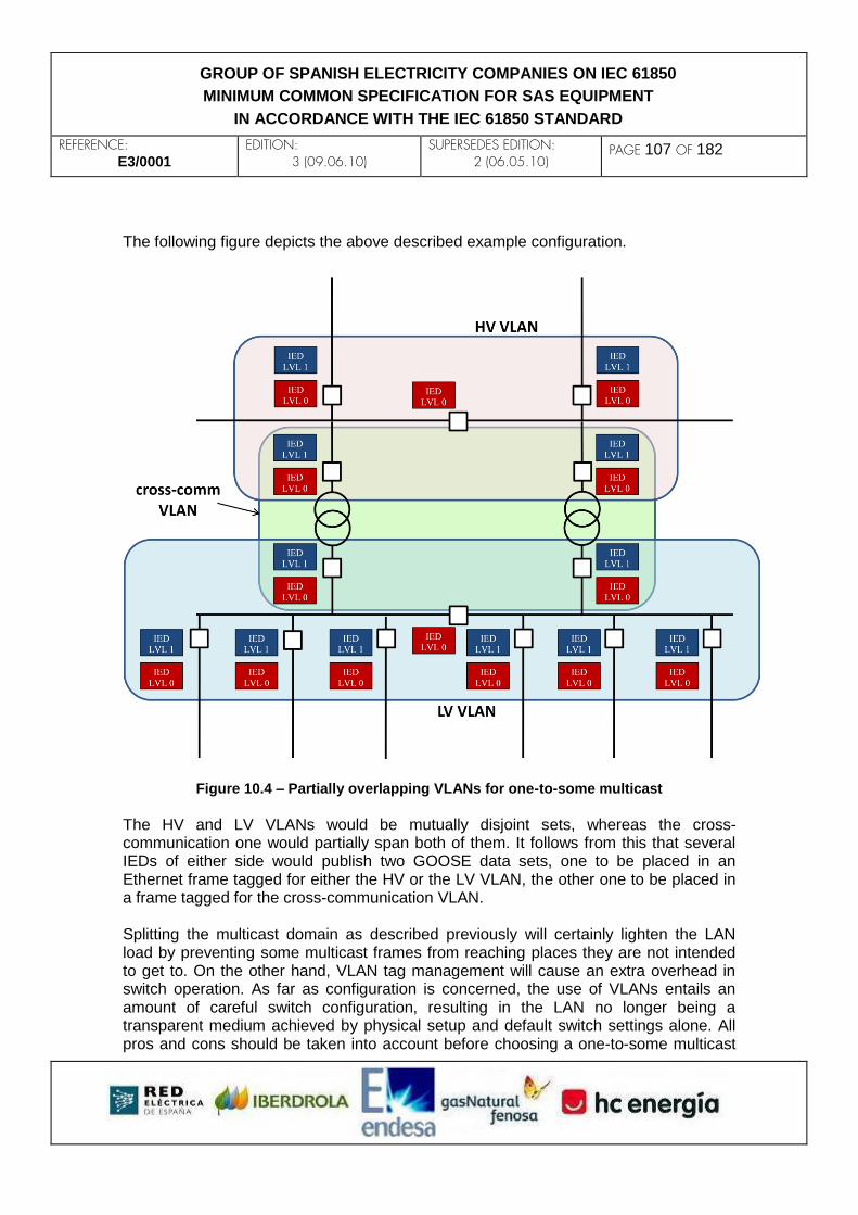
REFERENCE: E3/0001
EDITION: 3 (09.06.10)
SUPERSEDES EDITION: 2 (06.05.10)
PAGE 107 OF 182
GROUP OF SPANISH ELECTRICITY COMPANIES ON IEC 61850
MINIMUM COMMON SPECIFICATION FOR SAS EQUIPMENT
IN ACCORDANCE WITH THE IEC 61850 STANDARD
The following figure depicts the above described example configuration.
Figure 10.4 – Partially overlapping VLANs for one-to-some multicast
The HV and LV VLANs would be mutually disjoint sets, whereas the cross-communication one would partially span both of them. It follows from this that several IEDs of either side would publish two GOOSE data sets, one to be placed in an Ethernet frame tagged for either the HV or the LV VLAN, the other one to be placed in a frame tagged for the cross-communication VLAN. Splitting the multicast domain as described previously will certainly lighten the LAN load by preventing some multicast frames from reaching places they are not intended to get to. On the other hand, VLAN tag management will cause an extra overhead in switch operation. As far as configuration is concerned, the use of VLANs entails an amount of careful switch configuration, resulting in the LAN no longer being a transparent medium achieved by physical setup and default switch settings alone. All pros and cons should be taken into account before choosing a one-to-some multicast

REFERENCE: E3/0001
EDITION: 3 (09.06.10)
SUPERSEDES EDITION: 2 (06.05.10)
PAGE 108 OF 182
GROUP OF SPANISH ELECTRICITY COMPANIES ON IEC 61850
MINIMUM COMMON SPECIFICATION FOR SAS EQUIPMENT
IN ACCORDANCE WITH THE IEC 61850 STANDARD
approach for GOOSE communication.
10.5 SV-mapped process level functions As stated in the introduction, the logical interface 4 is mapped according to IEC 61850-9. Only IEC 61850-9-2 (transmission of SV over Ethernet) will be considered in this document. More specifically, the present specification will adhere to a long extent, although not completely, to the ‘Implementation Guideline for Digital Interface to Instrument Transformers using IEC 61850-9-2’. Frequently referred to as ‘IEC 61850-9-2 Lite Edition’, or ‘9-2 LE’ for short, this document is a subset of IEC 61850-9-2 and was published by UCA in 2004. The purpose of SV is the transmission of samples of a continuosly-varying magnitude from a source IED to a sink IED. The source IED can be a device having an interface to the physical world, plus the capability to sample one or more physical magnitudes and, with or without additional processing, send a stream of samples to the sink IED. The additional processing could be rms calculation, phasor extraction, active and reactive power calculation, etc. A source IED with additional processing capabilities would be able to send samples of these calculated magnitudes instead of, or together with, the primary samples. The sink IED would be a device using the samples for one or more of the following purposes:
Making a decision (e.g. a protection device)
Storing the information contained in the stream of samples, with possibly some summarization or integration (e.g. a metering device)
Sending the information online, with possibly some summarization or integration, to upper levels of the telecontrol system, by means of protocols slower than SV (e.g. a bay device which sends measurements to the local or global SCADA via an IEC 61850 reporting service).
10.5.1 Requirements of SV transmission Reliability (delivery assurance) and performance (low transfer time) are requisites for SV transmission in the same way as they are for GOOSE transmission. A new requisite, namely time coherence, is specific of SV. Additionally, a specific discussion on network transmission rate is required for SV since, as will be explained in 10.5.1.4, insufficient network capacity may eventually lead to frame loss (poor reliability) and/or high frame delays (poor performance), even if no pathological flooding is present. 10.5.1.1 Reliability (delivery assurance): no frames lost

REFERENCE: E3/0001
EDITION: 3 (09.06.10)
SUPERSEDES EDITION: 2 (06.05.10)
PAGE 109 OF 182
GROUP OF SPANISH ELECTRICITY COMPANIES ON IEC 61850
MINIMUM COMMON SPECIFICATION FOR SAS EQUIPMENT
IN ACCORDANCE WITH THE IEC 61850 STANDARD
The impact of frame and therefore of sample loss must be assessed with respect to the particular application. In a metering, HMI display or SCADA recording application, the occasional loss of a few samples should not have a relevant impact. In a protection application, however, the loss of a small number of consecutive samples during a fault on the power network would probably cause abortion and restart of the fault detection process, which would result in delayed clearance. Since, for performance reasons, most implementations of SV place several consecutive samples of a given physical magnitude in each Ethernet frame, it follows from the above reasoning that the loss of a single frame is unacceptable in protection applications. NOTE: It must be remembered that the SV protocol does not provide a mechanism for the detection and resending of lost frames (neither does GOOSE). The two-tier constraint
Bearing in mind the resolution stated in 10.3.1.1 in favour of the most robust IED layouts, and particularly those having the least serial complexity, multi-tier arrangements shall not be accepted, such as those having intermediate IEDs which concentrate samples from ‘downstream’ IEDs and send them, with or without additional processing, to ‘upstream’ IEDs. In other words, only 2-tier applications shall be considered, i.e. those where
i) the SV-source IED acquires its input information in the form of an analog magnitude directly from the physical world, and
ii) the SV samples travel from the source IED to the sink IED without any
intermediate IED in-between, except possibly one or more Ethernet switches. The first of the above conditions allows the SV-source IED to be any kind of sensor, such as a non-conventional instrument transformer or an electronic device with analog inputs directly wired from a conventional instrument transformer, as long as its output is SV-coded. The concept of ‘merging unit’ is introduced in IEC 60044-7 and IEC 60044-8 (on electronic voltage and current transformers) to denote any device which merges into a single digital output a number of independent analog or digital streams corresponding to different physical magnitudes. Since the above sections reduce the term ‘merging unit’ to an equivalent of ‘SV-source IED’, for the purpose of this document only the latter denomination will be used. 10.5.1.2 Performance: 3 or 10 ms maximum transfer time With respect to SV performance specifically, the following two considerations must be made:
REFERENCE: E3/0001
EDITION: 3 (09.06.10)
SUPERSEDES EDITION: 2 (06.05.10)
PAGE 110 OF 182
GROUP OF SPANISH ELECTRICITY COMPANIES ON IEC 61850
MINIMUM COMMON SPECIFICATION FOR SAS EQUIPMENT
IN ACCORDANCE WITH THE IEC 61850 STANDARD
i) SV frames will be normally much larger than GOOSE frames, which implies that frame times, accumulated frame times and network times will be larger as well. SV frame size can be reduced by placing fewer samples in each APDU; however, this would only reduce overall performance because of the resulting increase in overhead load.
ii) SV frames will be normally more numerous than GOOSE ones due to their higher production frequency in normal conditions. However, unlike what occurs to GOOSE traffic, their abundance is absolutely predictable in normal conditions. The risk of SV accidental flooding is therefore smaller.
In a metering application, the receiving IED can easily cope with big transfer times (up to several seconds) since it basically works as an information buffer. In an HMI display or SCADA recording application, SV transfer times might be moderate (up to a few tenths of a second) and still be a fraction of the overall latency. In a protection application, since SV delays are net contributors to the total fault clearance time, they must be lower than a few milliseconds. IEC 61850-5 sets a lower limit of 3 ms (performance class P3) and an upper limit of 10 ms (performance class P1). Frame delay variation (FDV) can be described as the absolute value of the difference between the expected time of arrival of a frame (calculated on the basis of average transfer time) and the real time of arrival. As far as the FDV is concerned, if a protection IED is subscribed to more than one sample streams (a voltage and a current intensity, for instance), it must have the buffering capability necessary to make up for the worst case, that is, an accumulation of R*(2*D) samples of the non-delayed stream, where ‘R’ is the sampling rate and ‘D’ is the maximum possible FDV. Multicast versus unicast SV
As stated in 10.3.2.2, unicast SV is the best choice for a one-to-one application. For a one-to-many application, either plain multicast or segmented multicast shall be chosen. The discussion of 10.4.1.2.1 on muticast approaches for GOOSE also applies essentially for SV multicast. Impact of network capacity usage on performance
This subject is discussed at length in 10.5.1.4. 10.5.1.3 Time coherence
Time coherence ensures that an SV-receiving IED always knows when samples

REFERENCE: E3/0001
EDITION: 3 (09.06.10)
SUPERSEDES EDITION: 2 (06.05.10)
PAGE 111 OF 182
GROUP OF SPANISH ELECTRICITY COMPANIES ON IEC 61850
MINIMUM COMMON SPECIFICATION FOR SAS EQUIPMENT
IN ACCORDANCE WITH THE IEC 61850 STANDARD
coming from different SV sources are simultaneous (within a predetermined error margin) and can thus be correlated (e.g. for an impedance calculation). In principle, the resolution provided by a synchronizing method acceptable for control event correlation (such as SNTP, which provides a proven resolution of up to a few milliseconds) is not high enough to guarantee the time coherence demanded by an SV application. Four methods for achieving time coherence may be considered:
1) Source-synchronous sampling
If the samples to be correlated come from the same source IED and from the same publishing control block, and are placed in the same ASDU of the same frame, they must be simultaneous within a negligible margin.
If the samples to be correlated come from the same source IED but different publishing control blocks (that is, they belong to different datasets and travel in different frames), their local time tags (either a timestamp or a fixed-period counter) can be looked up by the receiving IED, which will still be able to correlate them.
In both the above cases it is assumed that the source IED’s design is such as to make internal delays (or at least those that are relevant to sample processing and timestamping) negligible in the context of the most demanding application that might use the SV data.
2) Limited-delay assumption
In certain cases, the design and architecture of the whole system (the source and sink IEDs, and the network connecting them), the time coherence requirements of the application that uses the SV data, or both, may allow to assume that the delays are kept below the acceptable maximum. Under this assumption, no process-bus-specific synchronization mechanism would be necessary. (The IEDs would probably be synchronized by a coarser method like SNTP, which would anyway provide a certain degree of synchronization.)
3) Fixed delay
The receiving IED knows the delay difference between the different sample streams and applies the corresponding offset. This method only works when both delays (or at least its mutual difference) are constant and known. The protocol must supply a mechanism to that purpose.

REFERENCE: E3/0001
EDITION: 3 (09.06.10)
SUPERSEDES EDITION: 2 (06.05.10)
PAGE 112 OF 182
GROUP OF SPANISH ELECTRICITY COMPANIES ON IEC 61850
MINIMUM COMMON SPECIFICATION FOR SAS EQUIPMENT
IN ACCORDANCE WITH THE IEC 61850 STANDARD
4) Synchronized sampling
A stand-alone synchronization server (such as a one-pulse-per-second server) keeps all sampling IEDs synchronized, by means of signals transmited through dedicated point-to-point connections. This solution shall be called ‘external synchronization’.
The SV-sink IED (or SV ‘client’) is, at the same time, the synchronization server, by means of signals transmitted through the process bus itself. This solution shall be called ‘client synchronization’.
The following figure shows schematically the synchronized sampling alternatives.
Figure 10.5 – Synchronized sampling alternatives
The limited-delay assumption and the fixed delay method are unadvisable in either a switched Ethernet or a point-to-point Ethernet with non-dedicated connections, where the probability of non-zero FDV (frame delay variation) is considerable. Moreover, the fixed delay method requires non-trivial offset calculation in the receiving IED. To a certain extent, the client synchronization method also presents the first of the above disadvantages. However, some retardation tolerance for the synchronization signal, together with reliable clocks within the sampling IEDs, can neutralize small
REFERENCE: E3/0001
EDITION: 3 (09.06.10)
SUPERSEDES EDITION: 2 (06.05.10)
PAGE 113 OF 182
GROUP OF SPANISH ELECTRICITY COMPANIES ON IEC 61850
MINIMUM COMMON SPECIFICATION FOR SAS EQUIPMENT
IN ACCORDANCE WITH THE IEC 61850 STANDARD
FDVs in a very consistent way. At the present stage of the analyses carried out by the E3 Group, it seems advisable to adopt, at least, the time coherence requirements declared in the ‘Implementation Guideline for Digital Interface to Instrument Transformers using IEC 61850-9-2’ (henceforth, ‘9-2 LE’). This implies:
Non-synchronized (i.e. limited delay or fixed delay) methods are discarded.
The synchronization messages shall have an accuracy of ± 1 microsecond or better (at the origin).
The sampling IED (and SV source) numbers the samples, and a new count starts upon reception of each synchronization message (with a certain tolerance for message retardation).
Although 9-2 LE mentions ‘an external time reference’, client synchronization can be assumed to be implicitly compatible with this specification.
9-2 LE specifies that the synchronization message shall be ‘one pulse per second’ (1PPS). However, methods that can provide a still higher resolution (e.g. IEEE 1588 or IRIG-B) will also be accepted. 10.5.1.4 Transmission rate The bit transmission rate of the network has not been considered as a relevant factor in the previous analysis of GOOSE-mapped process level functions, since under normal conditions they need to transmit a volume of data per time unit that is several orders of magnitude smaller than the capacity available in a 100 Mbps or a 1 Gbps network. This is not the case, however, with SV-mapped process level functions. An examination of these issues follows, based on the requirements assumed by the 9-2 LE specification. The sampling frequency and the sampling accuracy must not be less than whatever is imposed by the application. Both conditions, together with frame structure and headers, directly determine a bit rate that must fit comfortably under the network ceiling. If it does not, queues will soon grow in the sending IEDs as well as in the switches, which will cause degraded performance followed by frames getting lost. This problem is independent from pathological flooding and is a mere consequence of poor system design. It must be noted that, although pure SV data traffic is almost totally deterministic, traffic bumps can occur if the network also hosts GOOSE traffic or because of ancillary network processes such as redundancy protocols, ARP broadcasting, etc. For this reason, and because frame loss is not acceptable in SV, this protocol requires larger buffering memory than GOOSE alone, both in the sending IEDs and in the switches, to allow for these transitory traffic bumps. However, useful buffer sizes are limited by the transfer times acceptable (i.e. a too-late frame can be

REFERENCE: E3/0001
EDITION: 3 (09.06.10)
SUPERSEDES EDITION: 2 (06.05.10)
PAGE 114 OF 182
GROUP OF SPANISH ELECTRICITY COMPANIES ON IEC 61850
MINIMUM COMMON SPECIFICATION FOR SAS EQUIPMENT
IN ACCORDANCE WITH THE IEC 61850 STANDARD
just as bad as a missing frame). 9-2 LE proposes a choice of two sampling rates: 80 and 256 samples per cycle, and sample values of the ‘INT32’ attribute type, i.e. an accuracy of 31 bits plus one sign bit. Appendix D of 9-2 LE proves that this ‘satisfies the complete dynamic range required by all practical cases’, either for protection or for metering applications. For a stream of 256*60=15360 samples per second, and assuming that 8 consecutive samples of a particular electrical magnitude are placed in each frame and a frame size of around 1000 bytes (following the specification of clause 7.1.4 and appendix A of 9-2 LE), 15360/8=1920 frames i.e. roughly 2 megabytes or 16 megabits are transmitted per second, which is not so far below the theoretical limit of a 100 Mbps NIC. The above calculation shows that for the most demanding applications, careful design is needed and the concurrence of several SV streams or even an SV stream with GOOSE traffic must be avoided if the links are 100 Mbps. In that case, Gigabit Ethernet or link aggregation (between switches) may be necessary. The discussion of 10.3.2.2 applies entirely.
10.6 Process bus design alternatives The previous sections present a number of requirements for the process level functions that can, in principle, be met by many different process bus structures. However, no single layout is the best solution for all the requirements at the same time. Consequently, the process bus selection will, in any particular case, be based on a trade-off analysis. Intended as a framework for such analysis, and based on the above review, the following sections enumerate the fundamental design alternatives and the essential decision criteria. The alternatives are constrained by some technical requisites which are declared and are mandatory in the context of this specification.
10.6.1 Process bus versus no process bus The first decision to make is whether
a dedicated network (physical process bus) is set up for the process level functions, or
the process level functions will share the station bus with the other logical interfaces (i.e. no process bus)
In the latter case, a virtual process bus can still be obtained by VLAN splitting of the network.

REFERENCE: E3/0001
EDITION: 3 (09.06.10)
SUPERSEDES EDITION: 2 (06.05.10)
PAGE 115 OF 182
GROUP OF SPANISH ELECTRICITY COMPANIES ON IEC 61850
MINIMUM COMMON SPECIFICATION FOR SAS EQUIPMENT
IN ACCORDANCE WITH THE IEC 61850 STANDARD
Advantages of physical or virtual process bus: lower risk of flooding no contention with station bus client/server traffic better performance
Disadvantages of physical or virtual process bus: more switches and/or switch management needed more Ethernet ports needed in level-1 IEDs (only if physical) less flexible and scalable (only if physical) level-0 IEDs cannot communicate directly with level 2, i.e. level-1 IEDs must be
proxies (maybe only if physical) The advantages of virtual process bus clearly outweigh those of no process bus; hence, the latter shall be preferred for the simplest installations only, or when process level functions are not IEC-61850-communicated.
10.6.2 Switched versus point-to-point process bus Switched uses Ethernet switches. Point-to-point uses dedicated point-to-point Ethernet links with crossed RX/TX connectors. Advantages of switched Ethernet:
lower processing overhead at sending IEDs in one-to-many applications fewer Ethernet ports are needed in IEDs much more flexible and scalable much simpler wiring
Disadvantages of switched Ethernet: switches and switch management are needed introduces serial complexity intrinsically higher transfer times higher risk of flooding client synchronization not possible/advisable shared medium implies lower transmission rate: high-rate SV streams may not
be able to coexist demands careful dimensioning of the switches’ buffers (especially for SV)
No less than those of a switched Ethernet, point-to-point physical connectors shall always comply with international standards, in accordance with IEC 61850-9-2, so that interoperability is assured. This implies that proprietary physical connections shall not be accepted. Further details can be found in 10.6.7.
REFERENCE: E3/0001
EDITION: 3 (09.06.10)
SUPERSEDES EDITION: 2 (06.05.10)
PAGE 116 OF 182
GROUP OF SPANISH ELECTRICITY COMPANIES ON IEC 61850
MINIMUM COMMON SPECIFICATION FOR SAS EQUIPMENT
IN ACCORDANCE WITH THE IEC 61850 STANDARD
10.6.3 Segmented versus non-segmented process bus If the process bus is switched, it can be either segmented (divided into several multicast domains) or non-segmented (multicast frames go everywhere). It is inherent to a point-to-point process bus to be (physically) segmented. There are still two options if segmentation is chosen:
Physical segmentation with switched ‘islands’
Virtual segmentation (unicast SV, VLAN, MMRP multicast filtering) Advantages of segmentation: diminishes the risk of flooding typically increases effective transmission rate of network
Disadvantages of segmentation: (possibly) higher processing overhead at sending IEDs (if virtual) more complex engineering/maintenance (possibly) more Ethernet ports needed in IEDs (if physical) much less flexible and scalable (if physical)
As a general rule, if segmentation is chosen and a point-to-point solution is discarded, virtual rather than physical segmentation shall be preferred. Virtual segmentation shall be normally accomplished by unicasting (only available for SV), VLAN tagging or multicast filtering in switches.
10.6.4 Redundant versus non-redundant process bus Fundamental principle: the process bus layout must not hinder the zonal protection redundancy of a conventional substation. Unless seamless network redundancy is provided, latency-critical functions shall rely on backup protection in case of network failure. However, RSTP redundancy or no redundancy at all can still be considered depending on overall reliability requirements. The discussion in 10.3.1.4 applies.
10.6.5 Topology alternatives for a switched process bus The selection shall be based on:

REFERENCE: E3/0001
EDITION: 3 (09.06.10)
SUPERSEDES EDITION: 2 (06.05.10)
PAGE 117 OF 182
GROUP OF SPANISH ELECTRICITY COMPANIES ON IEC 61850
MINIMUM COMMON SPECIFICATION FOR SAS EQUIPMENT
IN ACCORDANCE WITH THE IEC 61850 STANDARD
Redundancy issues
Minimization of transfer time minimization of hops
The following alternatives may be considered (see complete discussion in 10.3.1.4):
A one-tier PRP process bus. Provides the best balance between reliability, performance, scalability and cost-effectiveness. Limit: maximum number of ports per switch.
A multi-tier PRP process bus. Provides very good reliability but higher latencies. A variant of this architecture is a PRP+RSTP double ring.
An HSR process bus. Provides very good reliability and still higher latencies than multi-tier PRP. It is expectably more economical than PRP.
Switched Ethernet with RSTP. Self-healing, but slow. Latency-critical functions shall rely on backup protection rather than RSTP redundancy.
Switched Ethernet with star topology and no redundancy. Latency-critical functions shall rely on backup protection.
10.6.6 Quality of service policies Quality of service policies administer the contention for shared resources so that the most critical pieces of communication are granted higher reliability and performance. As a general principle, the different types of communication can be classified as follows by ascending order of criticality:
1) client/server upstream
2) client/server downstream
3) SV
4) GOOSE
5) infrastructure services (redundancy protocol reconfiguration, self-diagnosis, network management, synchronization, etc.)
As far as process level functions are concerned, only the last three types are relevant. Regarding the component where the quality of service policies are applied, they can be classified into two categories:
1) Quality of service within the server or client IEDs

REFERENCE: E3/0001
EDITION: 3 (09.06.10)
SUPERSEDES EDITION: 2 (06.05.10)
PAGE 118 OF 182
GROUP OF SPANISH ELECTRICITY COMPANIES ON IEC 61850
MINIMUM COMMON SPECIFICATION FOR SAS EQUIPMENT
IN ACCORDANCE WITH THE IEC 61850 STANDARD
This must assure that processes of higher criticality do not have to wait for those of lower criticality within the IED. It is accomplished by correct design of the internal real-time operations of the IED. At the present moment, user-configurable quality of service (e.g. for assigning different priorities to different GOOSE applications) is not envisaged.
2) Quality of service within the Ethernet switches
This must assure that highly-critical frames are dispatched faster than less critical ones within the switch. The following mechanisms are available in most commercial Ethernet switches.
VLAN priority tagging (according to IEEE 802.1p, as a partial feature of IEEE 802.1Q). This mechanism allows the publishing IED to discretionally assign a priority to each frame. There are eight priority levels numbered 0 to 7 and coded as a 3-bit string placed in the 3rd octet of the IEEE 802.1Q tag.
Priority based on ingress port. This mechanism permits to assign a priority based on the port through which the frame enters the switch. This method is simpler, since the application is no longer required to tag the frames at origin; however, it is less convenient in a typical IEC 61850 installation, since a particular IED can be simultaneously the source of frames of dissimilar criticality.
Priority based on other criteria (origin MAC address, destination MAC address, frame size, Ethertype, APPID, etc.) These methods are not as standard as IEEE 802.1p or port priority; however, they might be considered.
Rate control at switch port level. This method permits to set a limit on the throughput of a port, depending on several criteria, and is essential to prevent pathological flooding. Unlike the previous ones, this is not (at least in an explicit way) a priority assignment method. A high degree of flexibility in the configuration would be desirable, including options such as:
Individual configuration of each port
Static and dynamic limit setting
Limitation criteria: ingress/egress; unicast, multicast or broadcast; Ethertype; APPID; VLAN ID/priority
Notification of close-to-limit (controlled by a certain configurable percentage) and limit-reached conditions

REFERENCE: E3/0001
EDITION: 3 (09.06.10)
SUPERSEDES EDITION: 2 (06.05.10)
PAGE 119 OF 182
GROUP OF SPANISH ELECTRICITY COMPANIES ON IEC 61850
MINIMUM COMMON SPECIFICATION FOR SAS EQUIPMENT
IN ACCORDANCE WITH THE IEC 61850 STANDARD
10.6.7 Physical connections and quality control of the optical fibre network In accordance with the recommendation of IEC 61850-9-2, 100Base-FX dual-fibre multimode links shall be used. The connectors shall be rugged enough as to endure the most stringent conditions possible in an open-air installation. Multimode 100Base-FX allows distances of up to about 2 kilometers, which will be enough for probably all practical scenarios. (Single-mode links would reach about 10 km.) In the future, 1000Base-SX (multimode, up to a few hundreds of meters) or 1000Base-LX (single-mode, up to about 5 kilometers) Gigabit Ethernet connections might be considered, specially for heavily solicited inter-switch links and for one-to-many SV sources or many-to-one SV sinks. Future connector technology might be considered as well, both for 100 Mbps or for Gigabit Ethernet. In large, air-insulated substations with level-0 IEDs placed at the switchyard and level-1 IEDs placed in a distant control building, a switched process bus based on a few level-0-concentrating switches and another few level-1-concentrating switches may be the best option, so as to minimize the number of fibre connections between the switchyard and the building. Apart from following the best practices with regard to the physical design, coating, laying and maintenance of the optical fibres, the installation must take full advantage of the self-diagnosis capabilities of IEC 61850, by means of the exchange of ‘alive-and-ready’ GOOSE signals between IEDs.
10.7 Three reasonable process bus scenarios For illustration purposes, the following sections describe three process bus architectures that may apply to a great number of substation types.
10.7.1 Virtual process bus This solution is the simplest architecture provided that a switched station bus is already present, and is compatible with a high level of reliability, although it may pose performance challenges. The process level functions are mapped to a virtual LAN (a virtual process bus) based on the same physical network as the station bus. Both the level-1 and the level-0 IEDs are connected through one or two Ethernet ports only, depending on the redundancy level of the station bus. If the redundancy is achieved through an end-node based protocol such as PRP or HSR, it must be implemented on both the level-1 and the

REFERENCE: E3/0001
EDITION: 3 (09.06.10)
SUPERSEDES EDITION: 2 (06.05.10)
PAGE 120 OF 182
GROUP OF SPANISH ELECTRICITY COMPANIES ON IEC 61850
MINIMUM COMMON SPECIFICATION FOR SAS EQUIPMENT
IN ACCORDANCE WITH THE IEC 61850 STANDARD
level-0 IEDs. Consequently, it is particularly appropriate when there are no SV-mapped process level functions, i.e. the level-0 IEDs are only used for the logical interfaces 3 and 5 (status indication, command execution, etc.) To guarantee a good quality of service for the process level functions, the use of VLAN priority tagging is recommended. The following figure shows an example of a virtual process bus implemented as a VLAN hosted by an RSTP ring. The ‘station’ VLAN interconnects the level-2 and level-1 IEDs but does not reach the level-0 IEDs. In turn, the ‘process’ VLAN interconnects the level-1 and the level-0 IEDs only. As a consequence, the Ethernet links of the level- 1 IEDs belong to both VLANs at the same time. (In a more complex solution, level-1 IEDs would have duplicated Ethernet ports so that each port would be assigned to one of the two VLANs.) It must be noted that this example assumes that there is no process level communication between bay groups. (There are, in fact, several isolated process busses, one per bay group, instead of a single process bus.) Should inter-group communication be required, the trunk links connecting the bay level switches with one another would belong to the ‘process’ VLAN as well.

REFERENCE: E3/0001
EDITION: 3 (09.06.10)
SUPERSEDES EDITION: 2 (06.05.10)
PAGE 121 OF 182
GROUP OF SPANISH ELECTRICITY COMPANIES ON IEC 61850
MINIMUM COMMON SPECIFICATION FOR SAS EQUIPMENT
IN ACCORDANCE WITH THE IEC 61850 STANDARD
Figure 10.6 – Virtual process bus hosted by an RSTP ring
10.7.2 Point-to-point non-redundant connections with non-redundant level-0 IEDs This is a switchless solution, which offers a high degree of performance, but restricted reliability. The following figure shows a schematic example of such scenario.
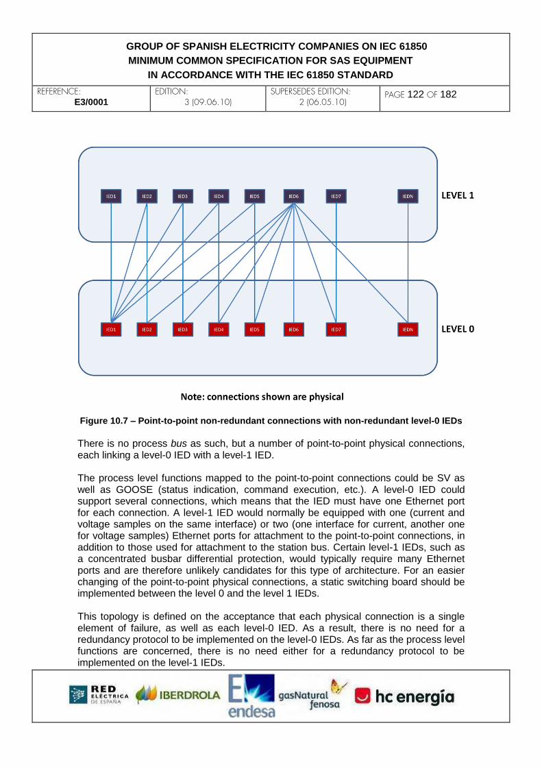
REFERENCE: E3/0001
EDITION: 3 (09.06.10)
SUPERSEDES EDITION: 2 (06.05.10)
PAGE 122 OF 182
GROUP OF SPANISH ELECTRICITY COMPANIES ON IEC 61850
MINIMUM COMMON SPECIFICATION FOR SAS EQUIPMENT
IN ACCORDANCE WITH THE IEC 61850 STANDARD
Figure 10.7 – Point-to-point non-redundant connections with non-redundant level-0 IEDs
There is no process bus as such, but a number of point-to-point physical connections, each linking a level-0 IED with a level-1 IED. The process level functions mapped to the point-to-point connections could be SV as well as GOOSE (status indication, command execution, etc.). A level-0 IED could support several connections, which means that the IED must have one Ethernet port for each connection. A level-1 IED would normally be equipped with one (current and voltage samples on the same interface) or two (one interface for current, another one for voltage samples) Ethernet ports for attachment to the point-to-point connections, in addition to those used for attachment to the station bus. Certain level-1 IEDs, such as a concentrated busbar differential protection, would typically require many Ethernet ports and are therefore unlikely candidates for this type of architecture. For an easier changing of the point-to-point physical connections, a static switching board should be implemented between the level 0 and the level 1 IEDs. This topology is defined on the acceptance that each physical connection is a single element of failure, as well as each level-0 IED. As a result, there is no need for a redundancy protocol to be implemented on the level-0 IEDs. As far as the process level functions are concerned, there is no need either for a redundancy protocol to be implemented on the level-1 IEDs.

REFERENCE: E3/0001
EDITION: 3 (09.06.10)
SUPERSEDES EDITION: 2 (06.05.10)
PAGE 123 OF 182
GROUP OF SPANISH ELECTRICITY COMPANIES ON IEC 61850
MINIMUM COMMON SPECIFICATION FOR SAS EQUIPMENT
IN ACCORDANCE WITH THE IEC 61850 STANDARD
10.7.3 Full process bus with redundant level-0 IEDs and seamless network redundancy This architecture is superior to the previous ones both in terms of performance and reliability, but is also more expensive. As opposed to the previously mentioned topologies, this one is a fully-redundant physical process bus. The level-0 IEDs are redundant and both the level-0 and the level-1 IEDs have two Ethernet ports each, for attachment to the process bus, in addition to those used for attachment to the station bus. The seamless network redundancy can be achieved by means of a PRP double star, a PRP+RSTP double ring or a High-availability Seamless Ring (HSR). The protocol must be implemented on both the level-1 and the level-0 IEDs. The following figure shows an example of this architecture based on a PRP double star LAN topology.
Figure 10.8 – Fully redundant process bus based on a PRP double star topology

REFERENCE: E3/0001
EDITION: 3 (09.06.10)
SUPERSEDES EDITION: 2 (06.05.10)
PAGE 124 OF 182
GROUP OF SPANISH ELECTRICITY COMPANIES ON IEC 61850
MINIMUM COMMON SPECIFICATION FOR SAS EQUIPMENT
IN ACCORDANCE WITH THE IEC 61850 STANDARD
A large number of alternative redundant architectures can stem from this one, by relaxation of the above mentioned requirements.

REFERENCE: E3/0001
EDITION: 3 (09.06.10)
SUPERSEDES EDITION: 2 (06.05.10)
PAGE 125 OF 182
GROUP OF SPANISH ELECTRICITY COMPANIES ON IEC 61850
MINIMUM COMMON SPECIFICATION FOR SAS EQUIPMENT
IN ACCORDANCE WITH THE IEC 61850 STANDARD
11. SYSTEM DEPLOYMENT This chapter proposes how to implant the IEC 61850 standard in a utility, bearing in mind the different scenarios that may be found, but without carrying out economic or technical assessments about their appropriateness. It is assumed that all the equipments have achieved all the functions described in this document. Due to the immaturity of the process bus, a further revision of this section is
not discarded in the future. According to the methodology used throughout this document, and only for this section, different types of installation plants are proposed with the aim of covering all or most of the cases that can be found in Spanish Electricity Companies
The installation types of plants on which the implementation is evaluated are the following:
1) Facilities with conventional control gear (Type A Plant: Outdoor installation)
2) Indoor facilities (Type B Plant: Indoor installation)
3) Joint Facilities (Type C Plant: Mixed Outdoor/Indoor installation)
11.1 Plant standard cases This section defines the installation plants that will be used as reference throughout this chapter.
11.2 Type A Plant: Outdoor installation These facilities are usual in sparsely populated areas with ease to achieve a large enough area for construction.

REFERENCE: E3/0001
EDITION: 3 (09.06.10)
SUPERSEDES EDITION: 2 (06.05.10)
PAGE 126 OF 182
GROUP OF SPANISH ELECTRICITY COMPANIES ON IEC 61850
MINIMUM COMMON SPECIFICATION FOR SAS EQUIPMENT
IN ACCORDANCE WITH THE IEC 61850 STANDARD
11.2.1 Type B Plant: Indoor installation These facilities are usual in densely populated zones with great difficulty to obtain large enough areas for the construction of ‘type A plants: outdoor installation’. This type of plant is necessary in areas with a great social demand of electrical installations invisibility.

REFERENCE: E3/0001
EDITION: 3 (09.06.10)
SUPERSEDES EDITION: 2 (06.05.10)
PAGE 127 OF 182
GROUP OF SPANISH ELECTRICITY COMPANIES ON IEC 61850
MINIMUM COMMON SPECIFICATION FOR SAS EQUIPMENT
IN ACCORDANCE WITH THE IEC 61850 STANDARD
11.2.2 Plant Type C mixed: Outdoor/Indoor installation
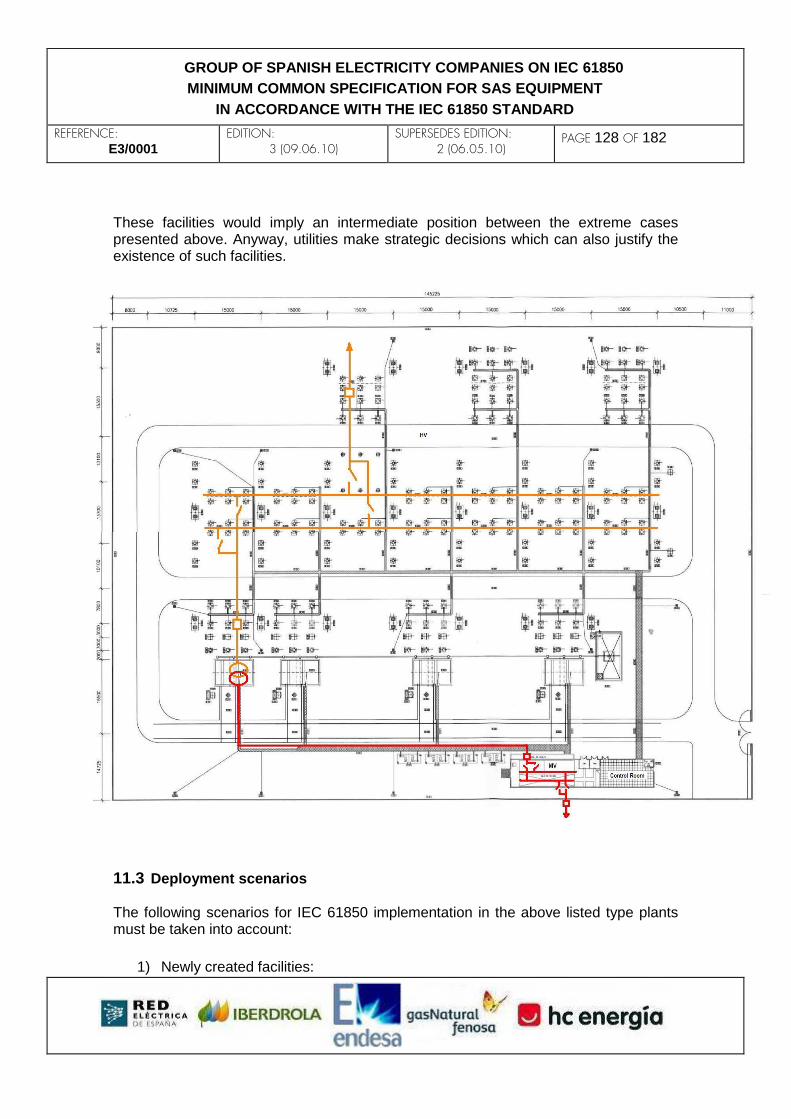
REFERENCE: E3/0001
EDITION: 3 (09.06.10)
SUPERSEDES EDITION: 2 (06.05.10)
PAGE 128 OF 182
GROUP OF SPANISH ELECTRICITY COMPANIES ON IEC 61850
MINIMUM COMMON SPECIFICATION FOR SAS EQUIPMENT
IN ACCORDANCE WITH THE IEC 61850 STANDARD
These facilities would imply an intermediate position between the extreme cases presented above. Anyway, utilities make strategic decisions which can also justify the existence of such facilities.
11.3 Deployment scenarios The following scenarios for IEC 61850 implementation in the above listed type plants must be taken into account:
1) Newly created facilities:

REFERENCE: E3/0001
EDITION: 3 (09.06.10)
SUPERSEDES EDITION: 2 (06.05.10)
PAGE 129 OF 182
GROUP OF SPANISH ELECTRICITY COMPANIES ON IEC 61850
MINIMUM COMMON SPECIFICATION FOR SAS EQUIPMENT
IN ACCORDANCE WITH THE IEC 61850 STANDARD
- Advantages:
The implantation takes place at 100% of the installation.
There is no need to maintain the service during implantation.
The automation benefits are obtained immediately and completely.
Investment in IEC 61850 is relatively easy to justify within the overall budget amount.
In general, new facilities represent a small part of the utilities current investment.
2) Remodeled or expanded facilities:
-Advantages
Investment can be made in a laminated way.
A remodeled facility can be justified by different reasons such as improving the safety of maintenance tasks, reducing failure rates, etc. With these justifications the utilities can take the opportunity to gradually implant IEC 61850 and pave the way to extend automation, with their added benefits.
-Disadvantages
The new implementation has to live together for long periods of time with older technologies.
The new implementation has to live together with very varied technologies.
Service maintenance during deployment is needed, and it must not affect their exploitation.
The benefits of new technologies are partially or fully mortgaged until the deployment of all new technology in that facility, which may take a long time to be achieved.
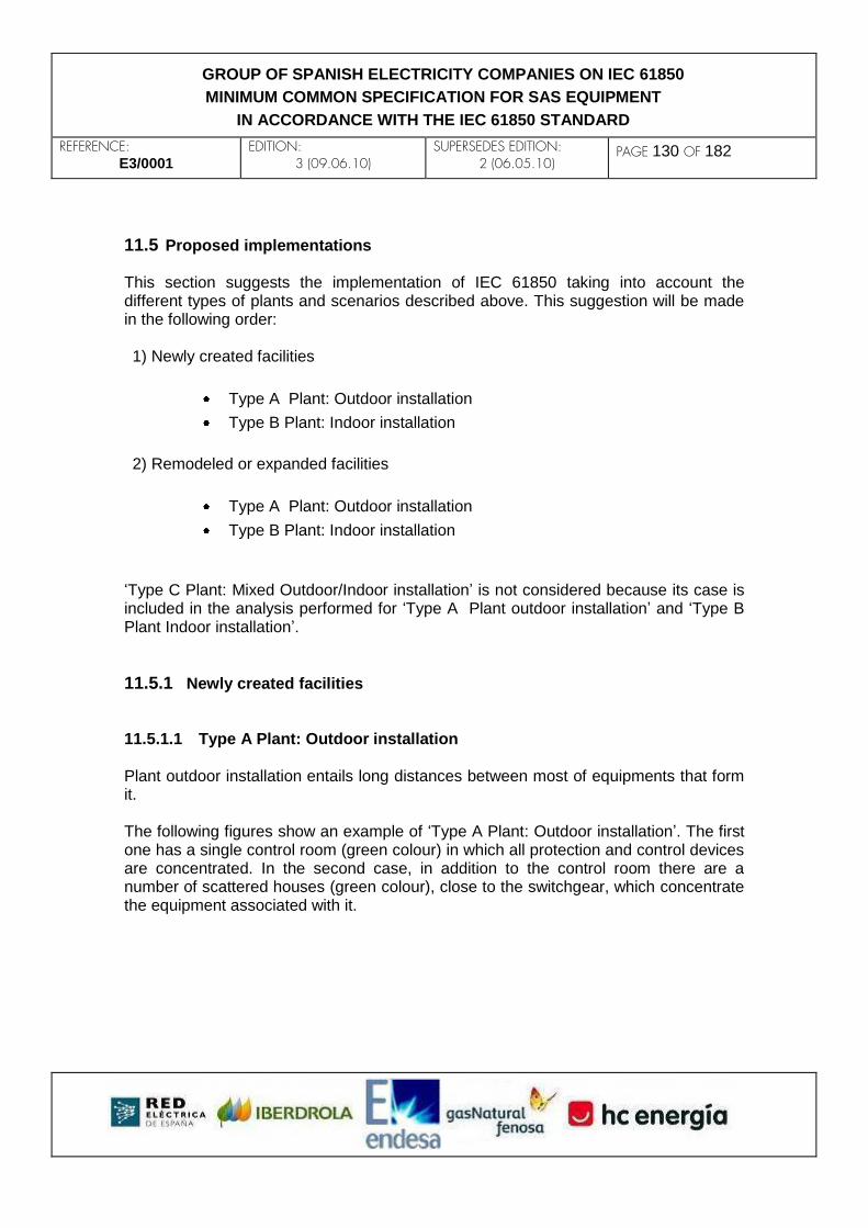
REFERENCE: E3/0001
EDITION: 3 (09.06.10)
SUPERSEDES EDITION: 2 (06.05.10)
PAGE 130 OF 182
GROUP OF SPANISH ELECTRICITY COMPANIES ON IEC 61850
MINIMUM COMMON SPECIFICATION FOR SAS EQUIPMENT
IN ACCORDANCE WITH THE IEC 61850 STANDARD
11.5 Proposed implementations This section suggests the implementation of IEC 61850 taking into account the different types of plants and scenarios described above. This suggestion will be made in the following order: 1) Newly created facilities
Type A Plant: Outdoor installation
Type B Plant: Indoor installation
2) Remodeled or expanded facilities
Type A Plant: Outdoor installation
Type B Plant: Indoor installation
‘Type C Plant: Mixed Outdoor/Indoor installation’ is not considered because its case is included in the analysis performed for ‘Type A Plant outdoor installation’ and ‘Type B Plant Indoor installation’.
11.5.1 Newly created facilities 11.5.1.1 Type A Plant: Outdoor installation Plant outdoor installation entails long distances between most of equipments that form it. The following figures show an example of ‘Type A Plant: Outdoor installation’. The first one has a single control room (green colour) in which all protection and control devices are concentrated. In the second case, in addition to the control room there are a number of scattered houses (green colour), close to the switchgear, which concentrate the equipment associated with it.

REFERENCE: E3/0001
EDITION: 3 (09.06.10)
SUPERSEDES EDITION: 2 (06.05.10)
PAGE 131 OF 182
GROUP OF SPANISH ELECTRICITY COMPANIES ON IEC 61850
MINIMUM COMMON SPECIFICATION FOR SAS EQUIPMENT
IN ACCORDANCE WITH THE IEC 61850 STANDARD
The following figures show that, applying IEC 61850 to the two previous cases, the areas of the station bus (blue color) and the process bus (red color) are very different.
In both cases the functional level of IEC 61850 implantation is the same and the features described in this document are accomplished without distinction. The level 0 IEDs belonging to the process bus are close to the switchgear. This does not eliminate or reduce conventional wiring, but minimizes its length. Additionally it can
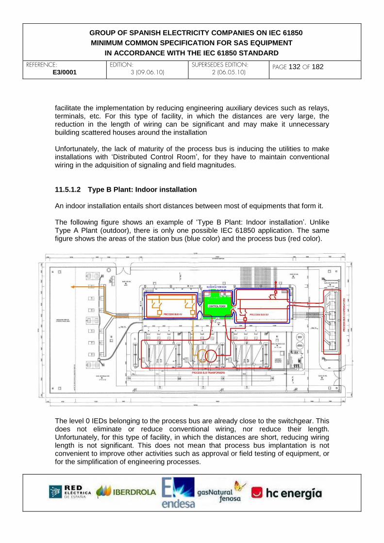
REFERENCE: E3/0001
EDITION: 3 (09.06.10)
SUPERSEDES EDITION: 2 (06.05.10)
PAGE 132 OF 182
GROUP OF SPANISH ELECTRICITY COMPANIES ON IEC 61850
MINIMUM COMMON SPECIFICATION FOR SAS EQUIPMENT
IN ACCORDANCE WITH THE IEC 61850 STANDARD
facilitate the implementation by reducing engineering auxiliary devices such as relays, terminals, etc. For this type of facility, in which the distances are very large, the reduction in the length of wiring can be significant and may make it unnecessary building scattered houses around the installation Unfortunately, the lack of maturity of the process bus is inducing the utilities to make installations with ‘Distributed Control Room’, for they have to maintain conventional wiring in the adquisition of signaling and field magnitudes. 11.5.1.2 Type B Plant: Indoor installation An indoor installation entails short distances between most of equipments that form it. The following figure shows an example of ‘Type B Plant: Indoor installation’. Unlike Type A Plant (outdoor), there is only one possible IEC 61850 application. The same figure shows the areas of the station bus (blue color) and the process bus (red color).
The level 0 IEDs belonging to the process bus are already close to the switchgear. This does not eliminate or reduce conventional wiring, nor reduce their length. Unfortunately, for this type of facility, in which the distances are short, reducing wiring length is not significant. This does not mean that process bus implantation is not convenient to improve other activities such as approval or field testing of equipment, or for the simplification of engineering processes.

REFERENCE: E3/0001
EDITION: 3 (09.06.10)
SUPERSEDES EDITION: 2 (06.05.10)
PAGE 133 OF 182
GROUP OF SPANISH ELECTRICITY COMPANIES ON IEC 61850
MINIMUM COMMON SPECIFICATION FOR SAS EQUIPMENT
IN ACCORDANCE WITH THE IEC 61850 STANDARD
Despite the extensive area of transformer and capacitor process bus, the number of their equipments will always be much lower than that of the equipments belonging to the HV and MV process bus. 11.5.1.3 Type C Plant: Mixed Outdoor/Indoor installation ‘Type C Plant: Mixed Outdoor/Indoor installation’ is not considered because this case is included in the analysis performed for ‘Type A Plant: Outdoor installation’ and ‘Type B Plant: Indoor installation’.
11.5.2 Remodeled or expanded facilities 11.5.2.1 Type A Plant: Outdoor installation The following figure shows a ‘Type A Plant: Outdoor installation’ in which the partial renovation to IEC 61850 is proposed only for the MV level. The Transformer and HV level will be kept with conventional wiring.

REFERENCE: E3/0001
EDITION: 3 (09.06.10)
SUPERSEDES EDITION: 2 (06.05.10)
PAGE 134 OF 182
GROUP OF SPANISH ELECTRICITY COMPANIES ON IEC 61850
MINIMUM COMMON SPECIFICATION FOR SAS EQUIPMENT
IN ACCORDANCE WITH THE IEC 61850 STANDARD
The largest complexity and problems would occur in the control room, where IEC 61850 must coexist with legacy systems. A particular company may choose to implement IEC 61850 to a greater or a lesser extent and thus get the facility more or less prepared for a full future implementation of IEC 61850.
In the expanded case, e.g., several new MV lines, the trouble-shooting and derived cases are identical to the remodeled case introduced in this section.
The utility can deploy to a greater or a lesser extent the IEC 61850 standard, based on their resources and / or future investment policies. As an example, 3 possible levels of implementation are detailed, ordered by lowest to highest commitment of the company to the deployment of IEC 61850. The latter approach is a clear commitment to achieve maximum substation automation in the future as soon as possible. 11.5.2.1.1 Minimum deployment in a conventional substation

REFERENCE: E3/0001
EDITION: 3 (09.06.10)
SUPERSEDES EDITION: 2 (06.05.10)
PAGE 135 OF 182
GROUP OF SPANISH ELECTRICITY COMPANIES ON IEC 61850
MINIMUM COMMON SPECIFICATION FOR SAS EQUIPMENT
IN ACCORDANCE WITH THE IEC 61850 STANDARD
The utility decides to keep the current wiring with the gateway to remote control center, changing to IEC 61850 the MV equipments and taking advantage of the process bus, which eliminates the conventional wiring. This decision can be conditioned by the existence of an ancient, non-updatable gateway to remote control center: its change may imply space problems or costs that the utility does not want to assume.

REFERENCE: E3/0001
EDITION: 3 (09.06.10)
SUPERSEDES EDITION: 2 (06.05.10)
PAGE 136 OF 182
GROUP OF SPANISH ELECTRICITY COMPANIES ON IEC 61850
MINIMUM COMMON SPECIFICATION FOR SAS EQUIPMENT
IN ACCORDANCE WITH THE IEC 61850 STANDARD
The IEC 61850 devices are connected to a small station bus, but the substation automation is very reduced and too located. 11.5.2.1.2 Intermediate deployment in a conventional substation Unlike the previous case, the hardware and software in the gateway to remote control center can be upgraded with one of the protocols currently approved by the utility. This eliminates the wiring in the MV control room. On the other hand, this requires installing new equipment between the gateway to remote control center and the IEC 61850 station bus.

REFERENCE: E3/0001
EDITION: 3 (09.06.10)
SUPERSEDES EDITION: 2 (06.05.10)
PAGE 137 OF 182
GROUP OF SPANISH ELECTRICITY COMPANIES ON IEC 61850
MINIMUM COMMON SPECIFICATION FOR SAS EQUIPMENT
IN ACCORDANCE WITH THE IEC 61850 STANDARD
The IEC 61850 devices are connected to a small station bus, but the substation automation is much reduced and too located. 11.5.2.1.3 Maximum deployment in a conventional substation This approach is a clear commitment to achieving maximum automation in the substation in the future as soon as possible. The architecture of the substation would be as shown in the image below. Because it is a remodeling, the ancient gateway to
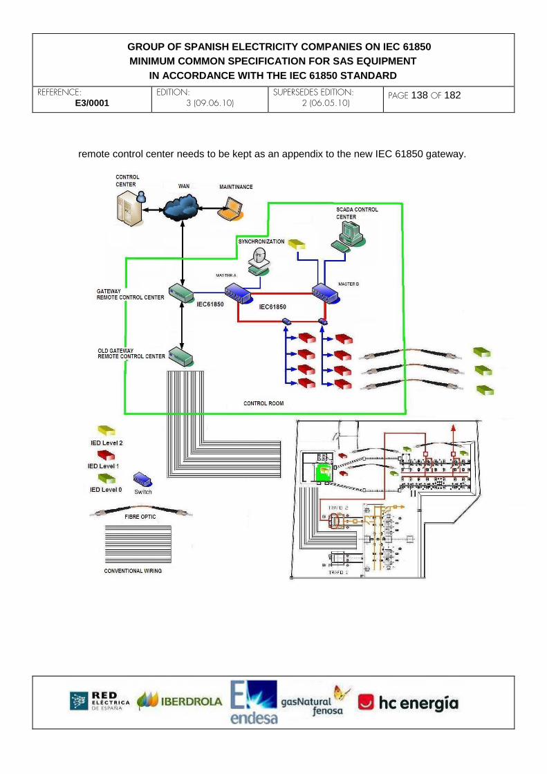
REFERENCE: E3/0001
EDITION: 3 (09.06.10)
SUPERSEDES EDITION: 2 (06.05.10)
PAGE 138 OF 182
GROUP OF SPANISH ELECTRICITY COMPANIES ON IEC 61850
MINIMUM COMMON SPECIFICATION FOR SAS EQUIPMENT
IN ACCORDANCE WITH THE IEC 61850 STANDARD
remote control center needs to be kept as an appendix to the new IEC 61850 gateway.

REFERENCE: E3/0001
EDITION: 3 (09.06.10)
SUPERSEDES EDITION: 2 (06.05.10)
PAGE 139 OF 182
GROUP OF SPANISH ELECTRICITY COMPANIES ON IEC 61850
MINIMUM COMMON SPECIFICATION FOR SAS EQUIPMENT
IN ACCORDANCE WITH THE IEC 61850 STANDARD
11.5.2.2 Type B Plants: Plant Indoor installation For ‘Type B Plants: Indoor installations’, the same analysis performed in ‘Type A Plant: outdoor installation’ can be applied. The following figure shows a ‘Type B Plant: Indoor installation’ in which the partial renovation to IEC 61850 is proposed only for the MV level. The transformer and the HV level will be kept with conventional wiring.
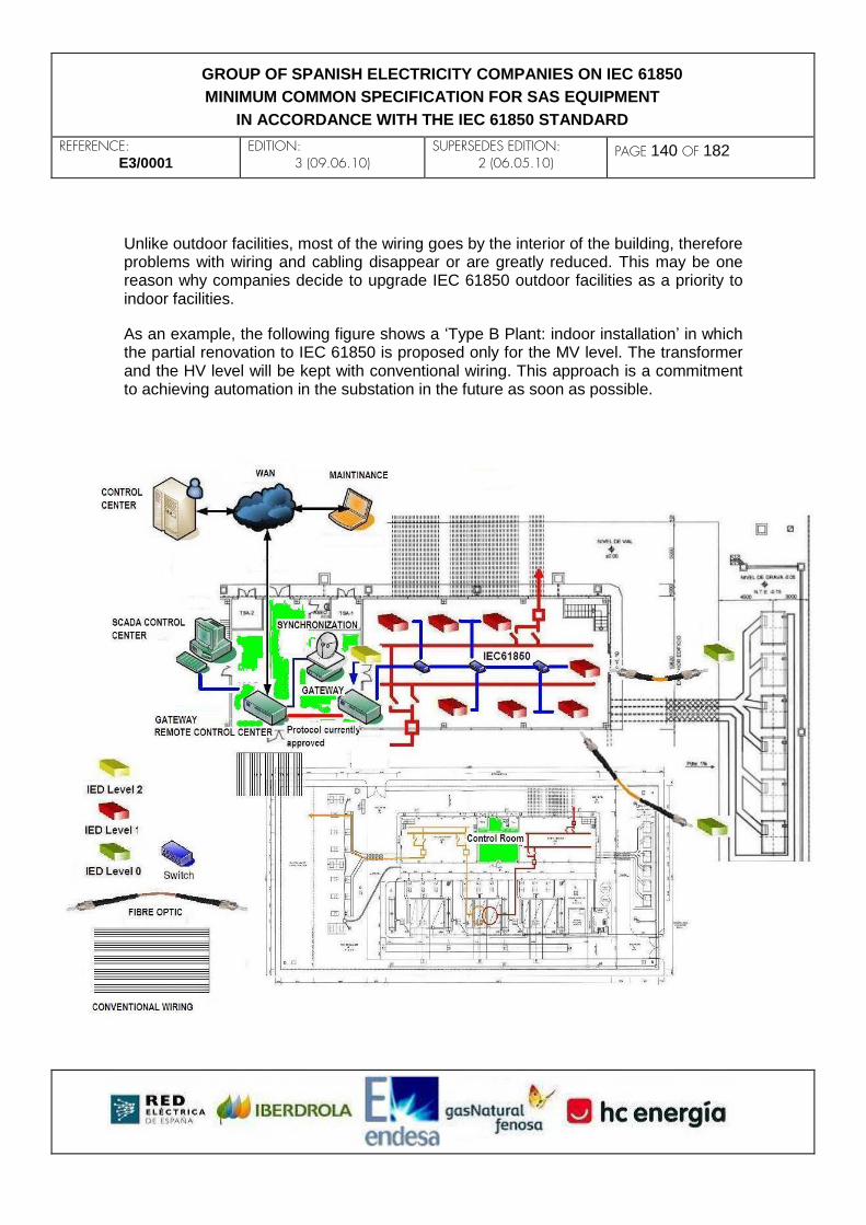
REFERENCE: E3/0001
EDITION: 3 (09.06.10)
SUPERSEDES EDITION: 2 (06.05.10)
PAGE 140 OF 182
GROUP OF SPANISH ELECTRICITY COMPANIES ON IEC 61850
MINIMUM COMMON SPECIFICATION FOR SAS EQUIPMENT
IN ACCORDANCE WITH THE IEC 61850 STANDARD
Unlike outdoor facilities, most of the wiring goes by the interior of the building, therefore problems with wiring and cabling disappear or are greatly reduced. This may be one reason why companies decide to upgrade IEC 61850 outdoor facilities as a priority to indoor facilities.
As an example, the following figure shows a ‘Type B Plant: indoor installation’ in which the partial renovation to IEC 61850 is proposed only for the MV level. The transformer and the HV level will be kept with conventional wiring. This approach is a commitment to achieving automation in the substation in the future as soon as possible.

REFERENCE: E3/0001
EDITION: 3 (09.06.10)
SUPERSEDES EDITION: 2 (06.05.10)
PAGE 141 OF 182
GROUP OF SPANISH ELECTRICITY COMPANIES ON IEC 61850
MINIMUM COMMON SPECIFICATION FOR SAS EQUIPMENT
IN ACCORDANCE WITH THE IEC 61850 STANDARD
11.5.3 Type C Plant: Mixed Outdoor/Indoor installation ‘Type C Plant: Mixed Outdoor/Indoor installation’ is not considered because this case is included in the analysis performed in ‘Type A Plant: outdoor installation’ and ‘Type B Plant: Indoor installation’.

REFERENCE: E3/0001
EDITION: 3 (09.06.10)
SUPERSEDES EDITION: 2 (06.05.10)
PAGE 142 OF 182
GROUP OF SPANISH ELECTRICITY COMPANIES ON IEC 61850
MINIMUM COMMON SPECIFICATION FOR SAS EQUIPMENT
IN ACCORDANCE WITH THE IEC 61850 STANDARD
A. ANNEX: MODELING OF LOGICS The logic implemented in the IEDs will be modeled as any other functionality. There are two different types of logic in an IED: fixed logic and editable logic. Fixed logics are included in the firmware of the IED and final users can only set the configurable fields of that logic. This type of logic is very easy to configure but has low flexibility. On the other hand, Editable Logics give the IED a high flexibility but with the disadvantage of a complex configurability. Therefore, in order to have a highly configurable IED which is at the same time simple enough to maintain, it shall have the following three facilities:
1) Use of fixed logic in all LNs.
2) Use of LN ‘InRef’ data objects.
3) Use of one dedicated LN to contain editable logics.
A.1 Fixed logic Any function modeled by one or more LNs is based on an internal logic that allows the IED to perform the function. This internal logic shall be fixed and is implemented by the manufacturer, based on the characteristic of the IED and the specifications of the utility. This logic shall not be modifiable by the user. The user shall only be able to modify the LN settings. All functions in an IED must be, by design, modeled using LNs, so the initial logic of a particular IED will be fixed. In addition to this, there may exist requirements for editable logics which are restricted to some special functions that might be necessary for the complete configuration of the IED. Therefore, the major part of an IED’s logic shall be considered as fixed and non modifiable, while a minor part shall be considered as editable and has to be modeled in order to provide some flexibility.
A.2 Application of ‘InRef’ data objects The IEC 61850 standard defines the use of ‘InRef’ data objects, in which references to data in another LN are used as inputs. Each LN shall have all necessary ‘InRef’ data objects that allow it to comply with its

REFERENCE: E3/0001
EDITION: 3 (09.06.10)
SUPERSEDES EDITION: 2 (06.05.10)
PAGE 143 OF 182
GROUP OF SPANISH ELECTRICITY COMPANIES ON IEC 61850
MINIMUM COMMON SPECIFICATION FOR SAS EQUIPMENT
IN ACCORDANCE WITH THE IEC 61850 STANDARD
functionality and the requirements of the utility. In the ‘setRef’ DA of each ‘InRef’ DO, the reference of the DO or DA to be used as an input for the LN shall be included.
LDName/LNName.DataObjectName[.SubDataObjectName[. ...]].DataAttributeName
A previous adaptation of the ‘Inputs’ element is necessary to simplify the setting of the fixed logic associated to a LN. This adaptation is one of the major components of any logic programming system, and it is convenient to reduce it as much as possible to make it a more easily configurable system. In order to achieve this, the expected value of the referenced signal shall be included next to that reference of an object being part of the ‘setRef’ DA. By using this method, the internal logic considers that the value of this input is true if the real value is one of the expected values; in case that the real value is different from the expected ones, the internal logic considers that the input value is false. The format shall be as follows:
LDName/LNName.DataObjectName…DataAttributeName…[SV1;SV2;…]
Together with the expected values of a signal, the following comparators might be included: when, >, <, >=, and so on.
A.3 Editable logic The use of editable logic should be reduced to some particular implementations that cannot be achieved by the above methods. Editable logic shall only be included in a dedicated LN that shall make use of a new Data Type. This new Data Type shall contain logical equations using the different inputs of this dedicated LN. This new DO shall be called ‘Logic’, and it shall be one DO inside the new Logic Setting (LS) CDC.

REFERENCE: E3/0001
EDITION: 3 (09.06.10)
SUPERSEDES EDITION: 2 (06.05.10)
PAGE 144 OF 182
GROUP OF SPANISH ELECTRICITY COMPANIES ON IEC 61850
MINIMUM COMMON SPECIFICATION FOR SAS EQUIPMENT
IN ACCORDANCE WITH THE IEC 61850 STANDARD
The value for the ‘setVal’ DA shall be a logical equation using IEC 61131; e.g.:
VAR5 := (VAR1 OR VAR2) AND (VAR3 OR VAR4)…;…;
The variables referenced by the logical equation shall be inputs of the same LN. The operators to be used shall be at least:
OR, AND, NOT, NOR, NAND, TON, TOF, IF
The LN designated to model the editable logics will be a GAPC LN with at least 16 Logic DOs. The table below represents this GAPC LN (# goes from 3 to 16):

REFERENCE: E3/0001
EDITION: 3 (09.06.10)
SUPERSEDES EDITION: 2 (06.05.10)
PAGE 145 OF 182
GROUP OF SPANISH ELECTRICITY COMPANIES ON IEC 61850
MINIMUM COMMON SPECIFICATION FOR SAS EQUIPMENT
IN ACCORDANCE WITH THE IEC 61850 STANDARD
Note: ‘ME’ means ‘mandatory by extension’; ‘OE’ means ‘optional by extension’. The ‘Ind’ DO will be used for mapping the result of the binary logic and the ‘IntIn’ DO will be used for mapping the result of the integer logics.
A.4 Example 1: fixed logic in a CALH logical node In this example, the following fixed logic associated to a CALH LN (Alarm Handling) is studied (this LN is used for grouping alarms of different types):
The ‘GrWrn’ DO is activated when any non urgent alarm is activated.
The ‘GrAlm’ DO is activated when any urgent alarm is activated.

REFERENCE: E3/0001
EDITION: 3 (09.06.10)
SUPERSEDES EDITION: 2 (06.05.10)
PAGE 146 OF 182
GROUP OF SPANISH ELECTRICITY COMPANIES ON IEC 61850
MINIMUM COMMON SPECIFICATION FOR SAS EQUIPMENT
IN ACCORDANCE WITH THE IEC 61850 STANDARD
The different types of alarms for an IED depend on the mission of that IED in a particular bay in the substation. It is convenient that the same CALH LN is used in any substation and position, without changing the IED’s configuration, i.e. only customizing its settings so as to adapt the IED’s configuration to the new bay. In the ‘setRef’ DA of each ‘InRef’ DO, the reference to the signal to be used as an element in the logical equation is indicated. The ‘intAddr’ DA indicates if the signal generates a non urgent alarm or an urgent alarm, introducing the data where it will be used, either ‘GrWrn’ or ‘GrAlm’. The internal fixed logic will perform the grouping of all inputs associated to the ‘GrWrn’ DO and of all those associated to the ‘GrAlm’ DO. This fixed logic is very simple because only boolean values are used. If it were necessary to include complex or inverted values in the logical equation, they should be adapted by means of the previously explained signal adaptation method, which consists on reducing the possible values to just the expected values in the ‘setRef’ DA.

REFERENCE: E3/0001
EDITION: 3 (09.06.10)
SUPERSEDES EDITION: 2 (06.05.10)
PAGE 147 OF 182
GROUP OF SPANISH ELECTRICITY COMPANIES ON IEC 61850
MINIMUM COMMON SPECIFICATION FOR SAS EQUIPMENT
IN ACCORDANCE WITH THE IEC 61850 STANDARD
The above example shows how the CALH LN is configured using the expected values method:
GrAlm is activated by two physical inputs, LD1/GGIO1.Ind8.stVal = 1 or LD1/GGIO1.Ind20.stVal = 0.
GrWrn is activated by any of two possible statuses of one same breaker, the intermediate state and the bad state, LD1/XCBR1.Pos.stVal = 0 or LD1/XCBR1.Pos.stVal = 3.(also, GrWrn is activated with the physical input LD1/GGIO1.Ind15.stVal = 1).
A.5 Example 2: editable logic LOGGAPC In this example, one LOGGAPC LN instance is shown, including the modeling of the editable logics of one IED.
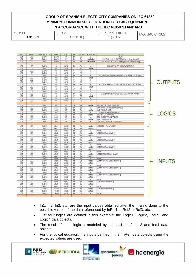
REFERENCE: E3/0001
EDITION: 3 (09.06.10)
SUPERSEDES EDITION: 2 (06.05.10)
PAGE 148 OF 182
GROUP OF SPANISH ELECTRICITY COMPANIES ON IEC 61850
MINIMUM COMMON SPECIFICATION FOR SAS EQUIPMENT
IN ACCORDANCE WITH THE IEC 61850 STANDARD
In1, In2, In3, etc. are the input values obtained after the filtering done to the possible values of the data referenced by InRef1, InRef2, InRef3, etc.
Just four logics are defined in this example: the Logic1, Logic2, Logic3 and Logic4 data objects.
The result of each logic is modeled by the Ind1, Ind2, Ind3 and Ind4 data objects.
For the logical equation, the inputs defined in the ‘InRef’ data objects using the expected values are used.

REFERENCE: E3/0001
EDITION: 3 (09.06.10)
SUPERSEDES EDITION: 2 (06.05.10)
PAGE 149 OF 182
GROUP OF SPANISH ELECTRICITY COMPANIES ON IEC 61850
MINIMUM COMMON SPECIFICATION FOR SAS EQUIPMENT
IN ACCORDANCE WITH THE IEC 61850 STANDARD
REFERENCE: E3/0001
EDITION: 3 (09.06.10)
SUPERSEDES EDITION: 2 (06.05.10)
PAGE 150 OF 182
GROUP OF SPANISH ELECTRICITY COMPANIES ON IEC 61850
MINIMUM COMMON SPECIFICATION FOR SAS EQUIPMENT
IN ACCORDANCE WITH THE IEC 61850 STANDARD
B. ANNEX: (INFORMATIVE) HMI AND GRAPHICAL SCREEN MODELING The HMI modeling solution described in this annex is a consequence of the research carried out to try to model as many IED´s configurable parts as possible and it is totally supported by some of the E3 group companies, while others are still studying it. The Human-Machine Interface (HMI) is one of the most important controllable elements in Substation Automation Systems (SAS). Like any other function, it shall be modeled.
B.1 HMI modeling The IEC 61850 standard defines the Logical Node (LN) IHMI for the modeling of the HMI function, but it is not completed. Using the extension rules of the IEC 61850 standard, it is possible to extend the LN IHMI for fully modeling the total functionality of the HMIs. One HMI have three types of elements:
Visual indicators.
Interaction buttons.
Graphic screens.
Visual indicators and Interaction Buttons can be modeled using standard data types as SPS, DPS, INS, SPC, etc. for status and actions, and data types ORG, ING, SPG, etc. for configuration. For modeling the Graphic Screens, it is necessary to introduce some graphical characteristics for the different elements that make the graphic screens up. Therefore, it becomes necessary to use a library of elements which would include the required graphic characteristics of any kind of elements that can be added in a graphical screen. Once the library exists, the LN IHMI only needs to define the configuration of each graphic element that makes the graphical screen and adjust all elements graphic characteristics. In order to include the information of each graphic element, a new CDC ‘Graphic Element’ is defined:

REFERENCE: E3/0001
EDITION: 3 (09.06.10)
SUPERSEDES EDITION: 2 (06.05.10)
PAGE 151 OF 182
GROUP OF SPANISH ELECTRICITY COMPANIES ON IEC 61850
MINIMUM COMMON SPECIFICATION FOR SAS EQUIPMENT
IN ACCORDANCE WITH THE IEC 61850 STANDARD
Attribute Name
Attribute Type
FC TrgOp Value / Value Range
M/O/C
DataName Inherited from Data Class (see IEC 61850-7-2)
DataAttribute
configuration, description and extension
elmRef VISIBLE STRING255 CF Library element or LN IHMI
M
strPosX INT32 CF Initial position of the element in the screen X
M
strPosY INT32 CF Initial position of the element in the screen Y
M
endPosX INT32 CF Final position of the element in the screen X
M
endPosY INT32 CF Final position of the element in the screen Y
M
elmCol VISIBLE STRING255 CF Element color M
elmWidth INT32 CF Element width M
elmTxt VISIBLE STRING255 CF Element text M
fonTyp VISIBLE STRING255 CF Font type M
elmMask VISIBLE STRING255 CF Element mask M
status1 VISIBLE STRING255 SP Status reference 1 M
action1 VISIBLE STRING255 SP Action reference 1 M
d VISIBLE STRING255 DC Description M
Services
GetDataValues, SetDataValues, GetDataDefinition
When modeling one graphic screen, the LN IHMI shall include two different types of information:
General information of the screen: Where the characteristics of the background area of the screen are defined.
Graphic Elements that are placed on the background to make up the single line diagram.
Attribute Name
Attr. Type
Description
Setting
XBase ING Background size (X axis)
YBase ING Background size (Y axis)
BaseColor ING Background colour

REFERENCE: E3/0001
EDITION: 3 (09.06.10)
SUPERSEDES EDITION: 2 (06.05.10)
PAGE 152 OF 182
GROUP OF SPANISH ELECTRICITY COMPANIES ON IEC 61850
MINIMUM COMMON SPECIFICATION FOR SAS EQUIPMENT
IN ACCORDANCE WITH THE IEC 61850 STANDARD
GrpElm1 GE Graphic Element 1
GrpElm2 GE Graphic Element 2
GrpElm # GE Graphic Element #
The library of elements will be defined by the utility, and the IED manufacturers will
generate their own library equivalent to the one of the utility.
B.2 Example 1: modeling of one simple screen In this example, a LN IHMI corresponding to a line (Linea 1) single line diagram of an IED HMI or even to a SCADA HMI is modeled.
In this example, the graphic screen can be divided into a background area and five graphic elements to be placed on it.
The library used and defined by the utility could be as follows:

REFERENCE: E3/0001
EDITION: 3 (09.06.10)
SUPERSEDES EDITION: 2 (06.05.10)
PAGE 153 OF 182
GROUP OF SPANISH ELECTRICITY COMPANIES ON IEC 61850
MINIMUM COMMON SPECIFICATION FOR SAS EQUIPMENT
IN ACCORDANCE WITH THE IEC 61850 STANDARD
The graphic element number 1 has the following configuration:
Then the IHMI LN that models this graphical screen is:
LN DO CDC FC DA VALOR
IHMI 1 NamPlt LPL DC d D: LINE 1
IHMI 1 NamPlt LPL DC configRev 1 2010.02.01 10:24:35 [iSAS@Works:Jose Gonzalo]
IHMI 1 NamPlt LPL DC paramRev 1302 2010.03.10 15:07:11 [iSAS@Works:Jose Gonzalo]
IHMI 1 XBase ING SP setVal 120
IHMI 1 XBase ING CF minVal 1
IHMI 1 XBase ING CF maxVal 1000
IHMI 1 XBase ING CF stepSize 1
IHMI 1 XBase ING DC d X axis length
IHMI 1 YBase ING SP setVal 150
IHMI 1 YBase ING CF minVal 1
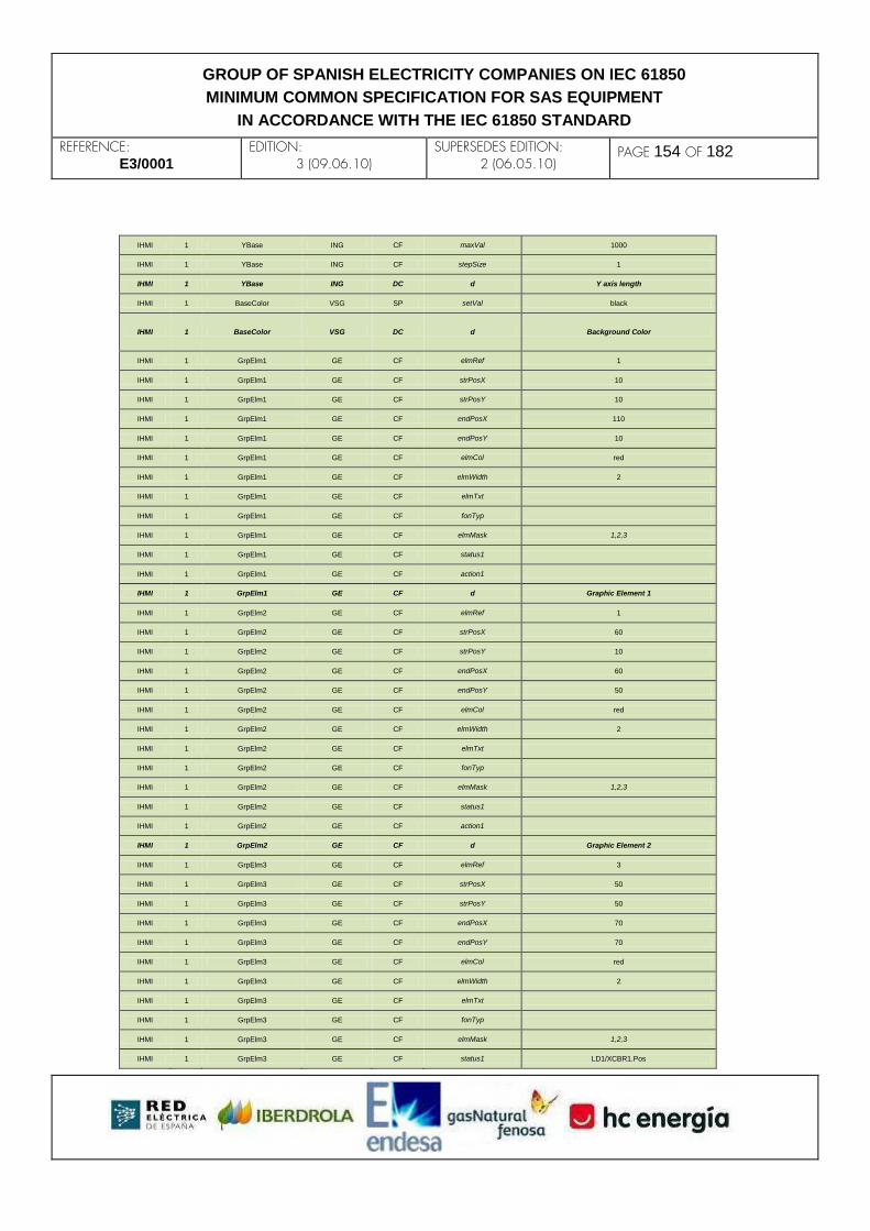
REFERENCE: E3/0001
EDITION: 3 (09.06.10)
SUPERSEDES EDITION: 2 (06.05.10)
PAGE 154 OF 182
GROUP OF SPANISH ELECTRICITY COMPANIES ON IEC 61850
MINIMUM COMMON SPECIFICATION FOR SAS EQUIPMENT
IN ACCORDANCE WITH THE IEC 61850 STANDARD
IHMI 1 YBase ING CF maxVal 1000
IHMI 1 YBase ING CF stepSize 1
IHMI 1 YBase ING DC d Y axis length
IHMI 1 BaseColor VSG SP setVal black
IHMI 1 BaseColor VSG DC d Background Color
IHMI 1 GrpElm1 GE CF elmRef 1
IHMI 1 GrpElm1 GE CF strPosX 10
IHMI 1 GrpElm1 GE CF strPosY 10
IHMI 1 GrpElm1 GE CF endPosX 110
IHMI 1 GrpElm1 GE CF endPosY 10
IHMI 1 GrpElm1 GE CF elmCol red
IHMI 1 GrpElm1 GE CF elmWidth 2
IHMI 1 GrpElm1 GE CF elmTxt
IHMI 1 GrpElm1 GE CF fonTyp
IHMI 1 GrpElm1 GE CF elmMask 1,2,3
IHMI 1 GrpElm1 GE CF status1
IHMI 1 GrpElm1 GE CF action1
IHMI 1 GrpElm1 GE CF d Graphic Element 1
IHMI 1 GrpElm2 GE CF elmRef 1
IHMI 1 GrpElm2 GE CF strPosX 60
IHMI 1 GrpElm2 GE CF strPosY 10
IHMI 1 GrpElm2 GE CF endPosX 60
IHMI 1 GrpElm2 GE CF endPosY 50
IHMI 1 GrpElm2 GE CF elmCol red
IHMI 1 GrpElm2 GE CF elmWidth 2
IHMI 1 GrpElm2 GE CF elmTxt
IHMI 1 GrpElm2 GE CF fonTyp
IHMI 1 GrpElm2 GE CF elmMask 1,2,3
IHMI 1 GrpElm2 GE CF status1
IHMI 1 GrpElm2 GE CF action1
IHMI 1 GrpElm2 GE CF d Graphic Element 2
IHMI 1 GrpElm3 GE CF elmRef 3
IHMI 1 GrpElm3 GE CF strPosX 50
IHMI 1 GrpElm3 GE CF strPosY 50
IHMI 1 GrpElm3 GE CF endPosX 70
IHMI 1 GrpElm3 GE CF endPosY 70
IHMI 1 GrpElm3 GE CF elmCol red
IHMI 1 GrpElm3 GE CF elmWidth 2
IHMI 1 GrpElm3 GE CF elmTxt
IHMI 1 GrpElm3 GE CF fonTyp
IHMI 1 GrpElm3 GE CF elmMask 1,2,3
IHMI 1 GrpElm3 GE CF status1 LD1/XCBR1.Pos

REFERENCE: E3/0001
EDITION: 3 (09.06.10)
SUPERSEDES EDITION: 2 (06.05.10)
PAGE 155 OF 182
GROUP OF SPANISH ELECTRICITY COMPANIES ON IEC 61850
MINIMUM COMMON SPECIFICATION FOR SAS EQUIPMENT
IN ACCORDANCE WITH THE IEC 61850 STANDARD
IHMI 1 GrpElm3 GE CF action1 LD1/CSWI1.Pos.Oper
IHMI 1 GrpElm3 GE CF d Graphic Element 3
IHMI 1 GrpElm4 GE CF elmRef 1
IHMI 1 GrpElm4 GE CF strPosX 60
IHMI 1 GrpElm4 GE CF strPosY 70
IHMI 1 GrpElm4 GE CF endPosX 60
IHMI 1 GrpElm4 GE CF endPosY 120
IHMI 1 GrpElm4 GE CF elmCol red
IHMI 1 GrpElm4 GE CF elmWidth 2
IHMI 1 GrpElm4 GE CF elmTxt
IHMI 1 GrpElm4 GE CF fonTyp
IHMI 1 GrpElm4 GE CF elmMask 1,2,3
IHMI 1 GrpElm4 GE CF status1
IHMI 1 GrpElm4 GE CF action1
IHMI 1 GrpElm4 GE CF d Graphic Element 4
IHMI 1 GrpElm5 GE CF elmRef 2
IHMI 1 GrpElm5 GE CF strPosX 30
IHMI 1 GrpElm5 GE CF strPosY 130
IHMI 1 GrpElm5 GE CF endPosX 90
IHMI 1 GrpElm5 GE CF endPosY 130
IHMI 1 GrpElm5 GE CF elmCol Red
IHMI 1 GrpElm5 GE CF elmWidth 2
IHMI 1 GrpElm5 GE CF elmTxt LINE 1
IHMI 1 GrpElm5 GE CF fonTyp Arial
IHMI 1 GrpElm5 GE CF elmMask 1,2,3
IHMI 1 GrpElm5 GE CF status1
IHMI 1 GrpElm5 GE CF action1
IHMI 1 GrpElm5 GE CF d Graphic Element 5
B.3 Example 2: modeling of a more complex screen
In this example, the IHMI LN of one general single line diagram screen of a SAS SCADA system is modeled.
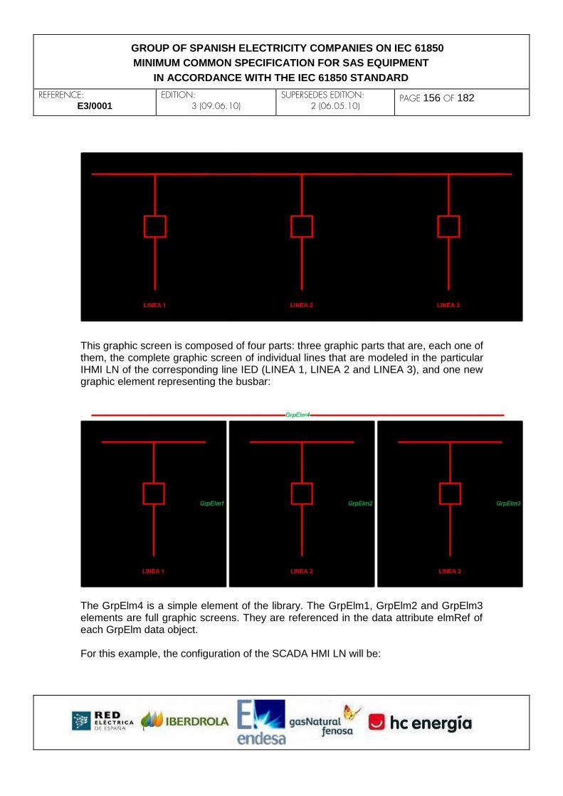
REFERENCE: E3/0001
EDITION: 3 (09.06.10)
SUPERSEDES EDITION: 2 (06.05.10)
PAGE 156 OF 182
GROUP OF SPANISH ELECTRICITY COMPANIES ON IEC 61850
MINIMUM COMMON SPECIFICATION FOR SAS EQUIPMENT
IN ACCORDANCE WITH THE IEC 61850 STANDARD
This graphic screen is composed of four parts: three graphic parts that are, each one of them, the complete graphic screen of individual lines that are modeled in the particular IHMI LN of the corresponding line IED (LINEA 1, LINEA 2 and LINEA 3), and one new graphic element representing the busbar:
The GrpElm4 is a simple element of the library. The GrpElm1, GrpElm2 and GrpElm3 elements are full graphic screens. They are referenced in the data attribute elmRef of each GrpElm data object. For this example, the configuration of the SCADA HMI LN will be:
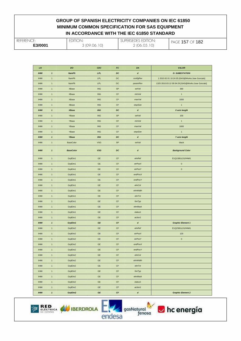
REFERENCE: E3/0001
EDITION: 3 (09.06.10)
SUPERSEDES EDITION: 2 (06.05.10)
PAGE 157 OF 182
GROUP OF SPANISH ELECTRICITY COMPANIES ON IEC 61850
MINIMUM COMMON SPECIFICATION FOR SAS EQUIPMENT
IN ACCORDANCE WITH THE IEC 61850 STANDARD
LN DO CDC FC DA VALOR
IHMI 1 NamPlt LPL DC d D: SUBESTATION
IHMI 1 NamPlt LPL DC configRev 1 2010.02.01 10:24:35 [iSAS@Works:Jose Gonzalo]
IHMI 1 NamPlt LPL DC paramRev 1325 2010.03.12 09:34:29 [iSAS@Works:Jose Gonzalo]
IHMI 1 XBase ING SP setVal 360
IHMI 1 XBase ING CF minVal 1
IHMI 1 XBase ING CF maxVal 1000
IHMI 1 XBase ING CF stepSize 1
IHMI 1 XBase ING DC d X axis length
IHMI 1 YBase ING SP setVal 150
IHMI 1 YBase ING CF minVal 1
IHMI 1 YBase ING CF maxVal 1000
IHMI 1 YBase ING CF stepSize 1
IHMI 1 YBase ING DC d Y axis length
IHMI 1 BaseColor VSG SP setVal black
IHMI 1 BaseColor VSG DC d Background Color
IHMI 1 GrpElm1 GE CF elmRef E1Q1SB1LD1/IHMI1
IHMI 1 GrpElm1 GE CF strPosX 0
IHMI 1 GrpElm1 GE CF strPosY 0
IHMI 1 GrpElm1 GE CF endPosX
IHMI 1 GrpElm1 GE CF endPosY
IHMI 1 GrpElm1 GE CF elmCol
IHMI 1 GrpElm1 GE CF elmWidth
IHMI 1 GrpElm1 GE CF elmTxt
IHMI 1 GrpElm1 GE CF fonTyp
IHMI 1 GrpElm1 GE CF elmMask
IHMI 1 GrpElm1 GE CF status1
IHMI 1 GrpElm1 GE CF action1
IHMI 1 GrpElm1 GE CF d Graphic Element 1
IHMI 1 GrpElm2 GE CF elmRef E1Q2SB1LD1/IHMI1
IHMI 1 GrpElm2 GE CF strPosX 120
IHMI 1 GrpElm2 GE CF strPosY 0
IHMI 1 GrpElm2 GE CF endPosX
IHMI 1 GrpElm2 GE CF endPosY
IHMI 1 GrpElm2 GE CF elmCol
IHMI 1 GrpElm2 GE CF elmWidth
IHMI 1 GrpElm2 GE CF elmTxt
IHMI 1 GrpElm2 GE CF fonTyp
IHMI 1 GrpElm2 GE CF elmMask
IHMI 1 GrpElm2 GE CF status1
IHMI 1 GrpElm2 GE CF action1
IHMI 1 GrpElm2 GE CF d Graphic Element 2

REFERENCE: E3/0001
EDITION: 3 (09.06.10)
SUPERSEDES EDITION: 2 (06.05.10)
PAGE 158 OF 182
GROUP OF SPANISH ELECTRICITY COMPANIES ON IEC 61850
MINIMUM COMMON SPECIFICATION FOR SAS EQUIPMENT
IN ACCORDANCE WITH THE IEC 61850 STANDARD
IHMI 1 GrpElm3 GE CF elmRef E1Q3SB1LD1/IHMI1
IHMI 1 GrpElm3 GE CF strPosX 240
IHMI 1 GrpElm3 GE CF strPosY 0
IHMI 1 GrpElm3 GE CF endPosX
IHMI 1 GrpElm3 GE CF endPosY
IHMI 1 GrpElm3 GE CF elmCol
IHMI 1 GrpElm3 GE CF elmWidth
IHMI 1 GrpElm3 GE CF elmTxt
IHMI 1 GrpElm3 GE CF fonTyp
IHMI 1 GrpElm3 GE CF elmMask
IHMI 1 GrpElm3 GE CF status1
IHMI 1 GrpElm3 GE CF action1
IHMI 1 GrpElm3 GE CF d Graphic Element 3
IHMI 1 GrpElm4 GE CF elmRef 1
IHMI 1 GrpElm4 GE CF strPosX 10
IHMI 1 GrpElm4 GE CF strPosY 10
IHMI 1 GrpElm4 GE CF endPosX 350
IHMI 1 GrpElm4 GE CF endPosY 10
IHMI 1 GrpElm4 GE CF elmCol Red
IHMI 1 GrpElm4 GE CF elmWidth 2
IHMI 1 GrpElm4 GE CF elmTxt
IHMI 1 GrpElm4 GE CF fonTyp
IHMI 1 GrpElm4 GE CF elmMask 2,3
IHMI 1 GrpElm4 GE CF status1
IHMI 1 GrpElm4 GE CF action1
IHMI 1 GrpElm4 GE CF d Graphic Element 4

REFERENCE: E3/0001
EDITION: 3 (09.06.10)
SUPERSEDES EDITION: 2 (06.05.10)
PAGE 159 OF 182
GROUP OF SPANISH ELECTRICITY COMPANIES ON IEC 61850
MINIMUM COMMON SPECIFICATION FOR SAS EQUIPMENT
IN ACCORDANCE WITH THE IEC 61850 STANDARD
C. ANNEX: QUALITY AND TIMESTAMP IN A CLIENT/SERVER CONTEXT This annex studies how to manage the quality and timestamp data attributes when the information is received from GOOSE messages or MMS information messages and mapped to an IEC 61850 server, according to what is defined in section 6.2 of IEC 61850-7-3. For example, an IED located in the bay level shall acquire information from IEDs located in the process level, and then it will send this information to station level acting as an IEC 61850 server. This IED would act as a GOOSE subscriber or MMS client in order to get information from the process bus, and would act as an IEC 61850 server in order to send information to the station level IEDs (or even another IEDs in the bay level). The following figure shows an example of such design:
As an IEC 61850 server, the IED 2 shall model the information received from GOOSE messages in data attributes grouped in logical nodes. For example, the dataset for a GOOSE message published by IED 1 has a ‘stVal’ DA and a ‘q’ DA of an SPS DO of the IED 2 IEC 61850 server model.

REFERENCE: E3/0001
EDITION: 3 (09.06.10)
SUPERSEDES EDITION: 2 (06.05.10)
PAGE 160 OF 182
GROUP OF SPANISH ELECTRICITY COMPANIES ON IEC 61850
MINIMUM COMMON SPECIFICATION FOR SAS EQUIPMENT
IN ACCORDANCE WITH THE IEC 61850 STANDARD
For every GOOSE message or MMS information message received from IED 1, the IED 2 decodes it and maps the information onto the IEC 61850 server model defined in its CID file. For example, the two data attributes received from the GOOSE message published by IED1 are mapped to the ‘Ind01’ SPS attribute of the instance logical nodel ‘GGIO1’. The ‘t’ DA will be updated with the timestamp of the last change of the ‘q’ or ‘stVal’ DA. Due to association lost/recover events, and possibly substitution and test actions on IED 2, the value of the mapped ‘q’, ‘t’ or ‘stVal’ DA shall not be an exact copy of the received ‘q’, ‘t’ and ‘stVal’ data attributes. In order to update the ‘LDName/GGIO1.Ind01.stVal’ DA, the IED2 should follow the following requirements:
1) If substitution is performed for the ‘stVal’ DA on the IED 2, then the value re-
ceived from the message will be ignored.
2) Otherwise, the ‘stVal’ DA will be a copy of the ‘stVal’ DA received from the
message.
In order to update the ‘LDName/GGIO1.Ind01.q’ DA, the IED2 should follow the following requirements:
1) If the association IED1IED2 is lost, the ‘validity’ field will be set to questiona-
ble, and the detailQual ‘oldData’ will be set. The rest of quality fields will not be
changed.
2) If the association IED1 IED2 is ok:
1. ‘validity’ field will be updated with the ‘validity’ field from the received ‘q’ DA.
2. ‘process’ field will be set to true if substitution was performed for this SPS attribute on the IED 2, o if the ‘process’ field from the received ‘q’ DA is set to true.
3. ‘test’ field will be set to true if the IED 2 is in test mode, or the ‘test’ field from the received ‘q’ DA is set to true.
4. ‘operatorBlocked’ field will be a copy of the ‘operatorBlocked’ field from the received ‘q’ DA.
5. ‘detailQual’ field will be a copy of the ‘detailQual’ field from the received ‘q’ DA, except possibly the ‘oscillatory’ bit if the IED 2 has such functionality for logical information.
In order to update the ‘LDName/GGIO1.Ind01.t’ DA, the IED2 should follow the

REFERENCE: E3/0001
EDITION: 3 (09.06.10)
SUPERSEDES EDITION: 2 (06.05.10)
PAGE 161 OF 182
GROUP OF SPANISH ELECTRICITY COMPANIES ON IEC 61850
MINIMUM COMMON SPECIFICATION FOR SAS EQUIPMENT
IN ACCORDANCE WITH THE IEC 61850 STANDARD
following requirements:
1) The ‘t’ DA will be automatically updated when a local change is done on
‘Ind01.stVal’ or ‘Ind01.q’ DA.
2) If the association IED1 IED2 is ok and the ‘t’ DA is transmitted from IED 1
(normally in MMS client/server context), then the ‘t’ DA will be an exact copy of
the received ‘t’ DA.
Additionally, if the SPS attribute is modeled with the substitution model (FC = SV), then an operator or IEC 61850 client could substitute the ‘stVal’ and ‘q’ data attributes with another values (subVal and subQ data attributes).

REFERENCE: E3/0001
EDITION: 3 (09.06.10)
SUPERSEDES EDITION: 2 (06.05.10)
PAGE 162 OF 182
GROUP OF SPANISH ELECTRICITY COMPANIES ON IEC 61850
MINIMUM COMMON SPECIFICATION FOR SAS EQUIPMENT
IN ACCORDANCE WITH THE IEC 61850 STANDARD
D. ANNEX: GOOSE AND SV SUBSCRIPTION MODELING It is considered necessary to model the subscription to SV and GOOSE messages of any IED and to give precise rules of implementation, because there are lots of types of different implementations in the market that reduce the interoperability of the IEC61850 standard based systems. D.1 Publisher’s side For the SV messages, the subscription model will be based on UCA’s ‘IEC 61850-9-2 Lite Edition’ which gives the rules about how to do it, stating the exact type of data to be sent in an SV message. This simplification makes the subscription and mapping of SV messages very easy because the information transmitted is fixed, and it also prevents from having different manufacturers´ implementations. In the case of GOOSE messages, it is not possible to state a common type of data to be transmitted in all of them, because each GOOSE message has different types of signals (i.e., Boolean signals, BitString signals…) that depend on the requirements of the user. Also, the order in which the signals are placed in the GOOSE message depends on the requirements of the final user. In order to increase the interoperability of IEDs for exchanging GOOSE messages, it is necessary to comply with two basic requirements:
1) Any type of simple attributes in an IED can be sent in a GOOSE message, no
matter its Functional Constraint. Therefore, attributes with FC of any type can
be sent in a GOOSE message.
2) Individual simple data attribute can be sent in GOOSE messages, i.e., the use
of the complete FCDA definition in the GOOSE data set.
D.2 Subscriber’s side Throughout this section, two options shall be defined to guarantee the interoperability and the configurability of the subscription to GOOSE and SV messages. D.2.1 Option A: Modeling of the subscription using only a subscribing LN Each IED´s subscription to a GOOSE or SV message will be modeled by a Logical Node (LN), which could be a GOSGGIO LN, a SVSGGIO LN or other possible new LN to be defined in the next IEC61850-7-4 Ed.2 as LGOS or LSVS:

REFERENCE: E3/0001
EDITION: 3 (09.06.10)
SUPERSEDES EDITION: 2 (06.05.10)
PAGE 163 OF 182
GROUP OF SPANISH ELECTRICITY COMPANIES ON IEC 61850
MINIMUM COMMON SPECIFICATION FOR SAS EQUIPMENT
IN ACCORDANCE WITH THE IEC 61850 STANDARD
Subscribing LN class
Data object name
Common data class
Explanation T M/O/C
LNName The name shall be composed of the class name, the LN-Prefix and LN-Instance-ID according to IEC 61850-7-2, Clause 22
Data objects
Status information
St SPS Status of the subscription (True = active, False=not active)
M
LastStNum INS Last state number received M
ConfRevNum INS Configuration revision number M
Settings
MAC VSG Publisher IED MAC address M
APPID ING GOOSE/SV message application identifier M
GoCBRef /SvCBRef
ORG Reference to the subscribed GOOSE/SV Control Block
M
GoDatSetRef /SvDatSetRef
ORG Reference to the subscribed GOOSE/SV Data Set M
GoID/SvID VSG Identification for the GOOSE/SV message M
ConfRev ING GOOSE/SV configuration revision number M
InRef# ORG Reference to data attributes received in the sub-scribed message
M
Note: # is a number which goes from 1 to N (N will be specified as needed).
The LN that models the subscription to a GOOSE or SV message must include the following information:
1- Status of the subscription.
2- Configuration of the subscription.
3- Mapping of signals received.
The status of the subscription The status of the subscription will be modeled according with the data included in the previous example table of the LN for subscribing to a GOOSE/SV message, with not only the presence of the ‘St’ data object for the status of the subscription, but also the ‘LastStNum’ and ‘ConfRevNum’ data objects, which shall be mandatory.

REFERENCE: E3/0001
EDITION: 3 (09.06.10)
SUPERSEDES EDITION: 2 (06.05.10)
PAGE 164 OF 182
GROUP OF SPANISH ELECTRICITY COMPANIES ON IEC 61850
MINIMUM COMMON SPECIFICATION FOR SAS EQUIPMENT
IN ACCORDANCE WITH THE IEC 61850 STANDARD
The configuration of the subscription
For the configuration of the subscription to a GOOSE/SV message, a future way of working might be to have IEDs with its client parts developed enough so they would have all information necessary for searching the information they need in other IEDs, subscribing to the GOOSE/SV message, obtaining the MAC address, the APPID field and checking the integrity of the GOOSE/SV message by means of the client services.
However, since IEDs do not have such capabilities today, the required information must be configured in the subscriber IED. The subscription could be configured including a data object in the subscriber LN (data object MAC (VSG) and data object APPID (ING)), as it is shown in the previous table. Therefore, in this option, it is not necessary to include either the IED section or the communication section where the dataset is modeled in the subscriber CID file, or the data for each publisher, because that structure is already considered in the subscribing LN configuration.
For different users or for different uses, it will be necessary to have different levels of surveillance of the subscription:
The simplest surveillance level focuses only on the MAC address and the APPID field, so, in this case, the IED will subscribe to any message with the right configured MAC address and APPID field.
In a more restrictive case, the IED will only subscribe if all the information included in the GOOSE/SV message is the same as is configured in the LN.
As stated before, if the IEDs were already self-configurable, these two different surveillance levels would not be necessary, as everything would be checked. The data that need to be checked in the last surveillance case explained and that have to be included in the subscribing LN, as stated in section 7.1.3 and represented in the above LN table, are listed below. They allow configuring the restrictions of subscription required for different users or for different uses:
o GoCBRef (ORG) / SvCBRef (ORG)
o GoDatSetRef (ORG) / SvDatSetRef (ORG)
o GoID (VSG) / SvID (VSG)
o ConfRev (ING)
REFERENCE: E3/0001
EDITION: 3 (09.06.10)
SUPERSEDES EDITION: 2 (06.05.10)
PAGE 165 OF 182
GROUP OF SPANISH ELECTRICITY COMPANIES ON IEC 61850
MINIMUM COMMON SPECIFICATION FOR SAS EQUIPMENT
IN ACCORDANCE WITH THE IEC 61850 STANDARD
The mapping of signals
The mapping of signals acquired from a GOOSE/SV message shall be performed by means of the ‘InRef’ data objects (also to be included in each subscribing LN in the subscriber IED). In order to realize the data set structure of the incoming GOOSE/SV message, the mapping destination of each incoming signal should be as follows: the InRef1 should correspond to data set entry 1 of the GOOSE/SV message; the InRef2, to the Data Set Entry 2; and so on. The subscriber IED shall be capable of mapping those signals acquired using the following procedure:
The acquired signals are stored inside the same subscribing LN. In this case, the ‘IntAddr’ data attribute in the ‘InRef’ data object contains a data attribute reference to a data object defined in the same subscribing LN. This information remains available for whatever the data or service which requires it within the subscribing IED This solution requires to have some predefined data of different classes in each subscribing LN, and they shall be defined as needed by every utility.
As can be deduced from the previous paragraph, there will be one subscribing LN for
each GOOSE/SV message in a subscriber IED, and the incoming message data are
stored inside the corresponding one. Apart from the data objects required for modeling
the status of the subscription and the configuration of the subscription already men-
tioned for a subscribing LN, some ‘InRef’ data objects are also demanded in the sub-
scribing LN to reference the incoming signals to the location where they will be stored
in each subscribing LN.
The mapping of the data included in a SV message is automatic because its structure is fixed. The LN that models the subscription to a SV message shall contain the data for the mapping of the voltage and current samples received. For GOOSE messages, this is not possible, because the information to transmit is not fixed. D.2.2 Option B: Modeling of the subscription through the publisher´s IED and Communication sections in the subscriber´s side In this option, the CID shall contain as many IED sections as publishers the subscriber IED is willing to subscribe to, plus the subscriber IED section. Therefore, the Communication section of the CID file shall also contain information about the subscriber and all of the publisher IEDs. The configuration of a subscription to a GOOSE or SV message implies the following:
3) The publisher IED section. It is not mandatory that the complete IED section of
the publisher appears in the CID file, but only all the information necessary for a
subscriber to get the GOOSE or SV information from the publisher.

REFERENCE: E3/0001
EDITION: 3 (09.06.10)
SUPERSEDES EDITION: 2 (06.05.10)
PAGE 166 OF 182
GROUP OF SPANISH ELECTRICITY COMPANIES ON IEC 61850
MINIMUM COMMON SPECIFICATION FOR SAS EQUIPMENT
IN ACCORDANCE WITH THE IEC 61850 STANDARD
4) The Communication section shall contain a ConnectedAP section for each pub-
lisher defining a GSE or SV section or both.
5) In the subscriber IED section, InRef data objects will be defined in the LNs con-
taining data objects / data attributes that have to be bound to the subscribed in-
formation.
In order to monitor the subscription to a GOOSE or SV message and to refine the spe-cification of fields that must be checked when validating a GOOSE or SV message, a LGOS or LSVS LN could be used, as explained below:
Subscribing logical node class:
Subscribing LN class
Data object name
Common data class
Explanation T M/O/C
LNName The name shall be composed of the class name, the LN-Prefix and LN-Instance-ID according to IEC 61850-7-2, Clause 22
Data objects
Status information
St SPS Status of the subscription (True = active, False=not active) M
LastStNum INS Last state number received M
ConfRevNum INS Configuration revision number M
Settings
GoCBRef / SmvCBRef
ORG Reference to the subscribed GOOSE/SV Control Block M
For a better monitoring of the status of the subscription, ‘LastStNum’ and ‘ConfRev-Num’ data objects shall be mandatory. D.3 Example of GOOSE suscription To clarify the above expounded concepts, an example is presented and resolved in the following sections. It is schematically shown in the following figure:

REFERENCE: E3/0001
EDITION: 3 (09.06.10)
SUPERSEDES EDITION: 2 (06.05.10)
PAGE 167 OF 182
GROUP OF SPANISH ELECTRICITY COMPANIES ON IEC 61850
MINIMUM COMMON SPECIFICATION FOR SAS EQUIPMENT
IN ACCORDANCE WITH THE IEC 61850 STANDARD
Figure 1 - Architecture of the example
The publisher (IED1) is a simple electronic device that gets information from a breaker in a wired, conventional way, and models this information into an IEC 61850 very primitive model. The IED uses a GGIO logical node to virtualize its eight (8) digital inputs in the following predefined configuration:
1. The first digital input is mapped to the DataAttribute ‘Ind01’ of the GGIO1 logical node instance. This digital input is wired to a Breaker Fault Indication.
2. The second digital input is mapped to the DataAttribute ‘Ind02’ of the GGIO1 logical node instance. This digital input is wired to the LOCAL/REMOTE selector of a breaker.

REFERENCE: E3/0001
EDITION: 3 (09.06.10)
SUPERSEDES EDITION: 2 (06.05.10)
PAGE 168 OF 182
GROUP OF SPANISH ELECTRICITY COMPANIES ON IEC 61850
MINIMUM COMMON SPECIFICATION FOR SAS EQUIPMENT
IN ACCORDANCE WITH THE IEC 61850 STANDARD
3. The other 6 digital inputs represent the breaker position, and are mapped to the DataAttribute ‘Dps01’ of the GGIO1 logical node instance. The IED implicitly converts the 6 digital inputs in a two-bit binary value.
A second IED, called IED 2, offers in its IEC 61850 model a logical node for the breaker failure (RBRF) and a logical node for the breaker (XCBR). However, in this example, the information of these logical nodes is not wired to the IED2, but linked to the wired information of IED1. IED1 will publish a GOOSE message with this information and the IED2 will subscribe to it. As shown in figure 1, the associations between IED1 DataObjects and IED2 DataObjects are the following:
IED1 DataObject/DataAttribute (source) IED2 DataObject/DataAttribute (target)
ADQ/GGIO1.Ind01.stVal,q ADQ/RBRF1.OpEx.general,q
ADQ/GGIO1.Ind02.stVal,q ADQ/XCBR1.Loc.stVal,q
ADQ/GGIO1.Dps01.stVal,q ADQ/XCBR1.Pos.stVal,q
These associations will be made through a single GOOSE message. D.3.1 IED1 CID file The IED1 CID file is simple, due to the predefined mapping of the wired information to the IEC 61850 model. The abbreviated contents of the CID file follow: <SCL>
<Header nameStructure="IEDName" id="IED1" version="1.0" revision="" toolID="">
<Text>Publisher IED1 sending fault signal and breaker position over Goose message</Text>
</Header>
<Communication>
<SubNetwork name="W01">
<ConnectedAP iedName="IED1" apName="IED1_AP1">
<Address>
<P type="IP">10.25.62.101</P>
<P type="IP-SUBNET">255.255.192.0</P>
<P type="IP-GATEWAY">10.25.1.1</P>
<P type="OSI-TSEL">0001</P>
<P type="OSI-PSEL">00000001</P>
<P type="OSI-SSEL">0001</P>
</Address>
<GSE ldInst="ADQ" cbName="CBIED1">
<Address>
<P type="MAC-Address">01-0C-CD-01-00-04</P>
<P type="APPID">1001</P>
<P type="VLAN-PRIORITY">4</P>
<P type="VLAN-ID">00A</P>
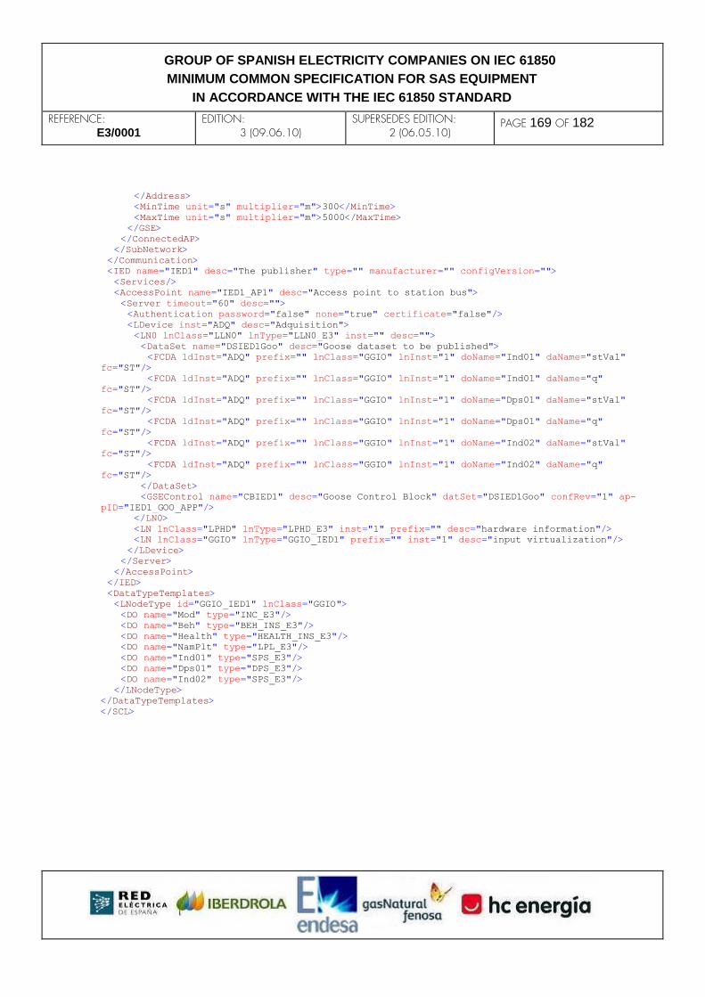
REFERENCE: E3/0001
EDITION: 3 (09.06.10)
SUPERSEDES EDITION: 2 (06.05.10)
PAGE 169 OF 182
GROUP OF SPANISH ELECTRICITY COMPANIES ON IEC 61850
MINIMUM COMMON SPECIFICATION FOR SAS EQUIPMENT
IN ACCORDANCE WITH THE IEC 61850 STANDARD
</Address>
<MinTime unit="s" multiplier="m">300</MinTime>
<MaxTime unit="s" multiplier="m">5000</MaxTime>
</GSE>
</ConnectedAP>
</SubNetwork>
</Communication>
<IED name="IED1" desc="The publisher" type="" manufacturer="" configVersion="">
<Services/>
<AccessPoint name="IED1_AP1" desc="Access point to station bus">
<Server timeout="60" desc="">
<Authentication password="false" none="true" certificate="false"/>
<LDevice inst="ADQ" desc="Adquisition">
<LN0 lnClass="LLN0" lnType="LLN0_E3" inst="" desc="">
<DataSet name="DSIED1Goo" desc="Goose dataset to be published">
<FCDA ldInst="ADQ" prefix="" lnClass="GGIO" lnInst="1" doName="Ind01" daName="stVal"
fc="ST"/>
<FCDA ldInst="ADQ" prefix="" lnClass="GGIO" lnInst="1" doName="Ind01" daName="q"
fc="ST"/>
<FCDA ldInst="ADQ" prefix="" lnClass="GGIO" lnInst="1" doName="Dps01" daName="stVal"
fc="ST"/>
<FCDA ldInst="ADQ" prefix="" lnClass="GGIO" lnInst="1" doName="Dps01" daName="q"
fc="ST"/>
<FCDA ldInst="ADQ" prefix="" lnClass="GGIO" lnInst="1" doName="Ind02" daName="stVal"
fc="ST"/>
<FCDA ldInst="ADQ" prefix="" lnClass="GGIO" lnInst="1" doName="Ind02" daName="q"
fc="ST"/>
</DataSet>
<GSEControl name="CBIED1" desc="Goose Control Block" datSet="DSIED1Goo" confRev="1" ap-
pID="IED1_GOO_APP"/>
</LN0>
<LN lnClass="LPHD" lnType="LPHD_E3" inst="1" prefix="" desc="hardware information"/>
<LN lnClass="GGIO" lnType="GGIO_IED1" prefix="" inst="1" desc="input virtualization"/>
</LDevice>
</Server>
</AccessPoint>
</IED>
<DataTypeTemplates>
<LNodeType id="GGIO_IED1" lnClass="GGIO">
<DO name="Mod" type="INC_E3"/>
<DO name="Beh" type="BEH_INS_E3"/>
<DO name="Health" type="HEALTH_INS_E3"/>
<DO name="NamPlt" type="LPL_E3"/>
<DO name="Ind01" type="SPS_E3"/>
<DO name="Dps01" type="DPS_E3"/>
<DO name="Ind02" type="SPS_E3"/>
</LNodeType>
</DataTypeTemplates>
</SCL>

REFERENCE: E3/0001
EDITION: 3 (09.06.10)
SUPERSEDES EDITION: 2 (06.05.10)
PAGE 170 OF 182
GROUP OF SPANISH ELECTRICITY COMPANIES ON IEC 61850
MINIMUM COMMON SPECIFICATION FOR SAS EQUIPMENT
IN ACCORDANCE WITH THE IEC 61850 STANDARD
D.3.2 Option A: Modeling of the subscription using only a subscribing LN This modeling option does not require either the IED or the Communication sections from the publisher IEDs to be added to the subscriber IED´s CID file. In the next example, only the MAC address, the APPID field and the data set reference are checked. If additional checks are desired, the corresponding data objects in the subscribing LN shall be configured. This option allows the changing of the subscription settings through the MMS services, as any other function within the IED. <SCL>
<Header nameStructure="IEDName" id="IED2" version="1.0" revision="" toolID="">
<Text>Annex D Goose Suscription Modeling Example, Option A</Text>
</Header>
<Communication>
<SubNetwork name="W01">
<ConnectedAP iedName="IED2" apName="IED2_AP1">
<Address>
<P type="IP">10.25.62.102</P>
<P type="IP-SUBNET">255.255.192.0</P>
<P type="IP-GATEWAY">10.25.1.1</P>
<P type="OSI-TSEL">0001</P>
<P type="OSI-PSEL">00000001</P>
<P type="OSI-SSEL">0001</P>
</Address>
</ConnectedAP>
</SubNetwork>
</Communication>
<IED name="IED2" desc="Subscriptor" type="" manufacturer="" configVersion="">
<Services/>
<AccessPoint name="IED2_AP1" desc="Access point">
<Server desc="">
<Authentication password="false" none="true" certificate="false"/>
<LDevice inst="ADQ" desc="Adquisition">
<LN0 lnClass="LLN0" lnType="LLN0_E3" inst="" desc=""/>
<LN lnClass="LPHD" lnType="LPHD_E3" inst="1" prefix="" desc=""/>
<LN lnClass="GGIO" lnType="GOSGGIO_E3" prefix="GOS" inst="1" desc="Monitoring of the Goose
received from IED1">
<DOI name="MAC">
<DAI name="setVal"><Val>01-CD-0C-01-00-04</Val></DAI>
</DOI>
<DOI name="APPID">
<DAI name="setVal"><Val>1001</Val></DAI>
</DOI>
<DOI name="GoCBRef">
<DAI name="setScrRef"><Val></Val></DAI>
</DOI>
<DOI name="GoDatSetRef">
<DAI name="setScrRef"><Val>IED1ADQ/LLN0.DSIED1Goo</Val></DAI>
</DOI>
<DOI name="GoID">
<DAI name="setVal"><Val></Val></DAI>
</DOI>
<DOI name="ConfRev">
<DAI name="setVal"><Val></Val></DAI>
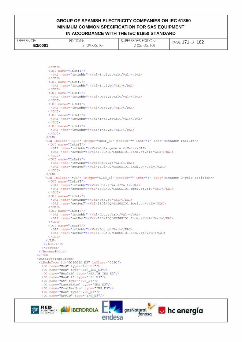
REFERENCE: E3/0001
EDITION: 3 (09.06.10)
SUPERSEDES EDITION: 2 (06.05.10)
PAGE 171 OF 182
GROUP OF SPANISH ELECTRICITY COMPANIES ON IEC 61850
MINIMUM COMMON SPECIFICATION FOR SAS EQUIPMENT
IN ACCORDANCE WITH THE IEC 61850 STANDARD
</DOI>
<DOI name="InRef1">
<DAI name="intAddr"><Val>Ind1.stVal</Val></DAI>
</DOI>
<DOI name="InRef2">
<DAI name="intAddr"><Val>Ind1.q</Val></DAI>
</DOI>
<DOI name="InRef3">
<DAI name="intAddr"><Val>Dps1.stVal</Val></DAI>
</DOI>
<DOI name="InRef4">
<DAI name="intAddr"><Val>Dps1.q</Val></DAI>
</DOI>
<DOI name="InRef5">
<DAI name="intAddr"><Val>Ind2.stVal</Val></DAI>
</DOI>
<DOI name="InRef6">
<DAI name="intAddr"><Val>Ind2.q</Val></DAI>
</DOI>
</LN>
<LN lnClass="RBRF" lnType="RBRF_E3" prefix="" inst="1" desc="Breaker Failure">
<DOI name="InRef1">
<DAI name="intAddr"><Val>OpEx.general</Val></DAI>
<DAI name="setRef"><Val>IED2ADQ/GOSGGIO1.Ind1.stVal</Val></DAI>
</DOI>
<DOI name="InRef2">
<DAI name="intAddr"><Val>OpEx.q</Val></DAI>
<DAI name="setRef"><Val>IED2ADQ/GOSGGIO1.Ind1.q</Val></DAI>
</DOI>
</LN>
<LN lnClass="XCBR" lnType="XCBR_E3" prefix="" inst="1" desc="Breaker 2-pole position">
<DOI name="InRef1">
<DAI name="intAddr"><Val>Pos.stVal</Val></DAI>
<DAI name="setRef"><Val>IED2ADQ/GOSGGIO1.Dps1.stVal</Val></DAI>
</DOI>
<DOI name="InRef2">
<DAI name="intAddr"><Val>Pos.q</Val></DAI>
<DAI name="setRef"><Val>IED2ADQ/GOSGGIO1.Dps1.q</Val></DAI>
</DOI>
<DOI name="InRef3">
<DAI name="intAddr"><Val>Loc.stVal</Val></DAI>
<DAI name="setRef"><Val>IED2ADQ/GOSGGIO1.Ind2.stVal</Val></DAI>
</DOI>
<DOI name="InRef4">
<DAI name="intAddr"><Val>Loc.q</Val></DAI>
<DAI name="setRef"><Val>IED2ADQ/GOSGGIO1.Ind2.q</Val></DAI>
</DOI>
</LN>
</LDevice>
</Server>
</AccessPoint>
</IED>
<DataTypeTemplates>
<LNodeType id="GOSGGIO_E3" lnClass="GGIO">
<DO name="Mod" type="INC_E3"/>
<DO name="Beh" type="BEH_INS_E3"/>
<DO name="Health" type="HEALTH_INS_E3"/>
<DO name="NamPlt" type="LPL_E3"/>
<DO name="St" type="SPS_E3"/>
<DO name="LastStNum" type="INS_E3"/>
<DO name="ConfRevNum" type="INS_E3"/>
<DO name="MAC" type="VSG_E3"/>
<DO name="APPID" type="ING_E3"/>
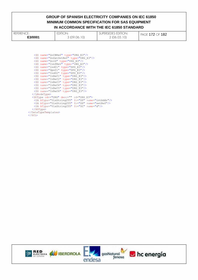
REFERENCE: E3/0001
EDITION: 3 (09.06.10)
SUPERSEDES EDITION: 2 (06.05.10)
PAGE 172 OF 182
GROUP OF SPANISH ELECTRICITY COMPANIES ON IEC 61850
MINIMUM COMMON SPECIFICATION FOR SAS EQUIPMENT
IN ACCORDANCE WITH THE IEC 61850 STANDARD
<DO name="GoCBRef" type="ORG_E3"/>
<DO name="GoDatSetRef" type="ORG_E3"/>
<DO name="GoID" type="VSG_E3"/>
<DO name="ConfRev" type="ING_E3"/>
<DO name="Ind01" type="SPS_E3"/>
<DO name="Dps01" type="DPS_E3"/>
<DO name="Ind02" type="SPS_E3"/>
<DO name="InRef1" type="ORG_E3"/>
<DO name="InRef2" type="ORG_E3"/>
<DO name="InRef3" type="ORG_E3"/>
<DO name="InRef4" type="ORG_E3"/>
<DO name="InRef5" type="ORG_E3"/>
<DO name="InRef6" type="ORG_E3"/>
</LNodeType>
<DOType cdc="ORG" desc="" id="ORG_E3">
<DA bType="VisString255" fc="SP" name="intAddr"/>
<DA bType="VisString255" fc="SP" name="setRef"/>
<DA bType="VisString255" fc="DC" name="d"/>
</DOType>
</DataTypeTemplates>
</SCL>

REFERENCE: E3/0001
EDITION: 3 (09.06.10)
SUPERSEDES EDITION: 2 (06.05.10)
PAGE 173 OF 182
GROUP OF SPANISH ELECTRICITY COMPANIES ON IEC 61850
MINIMUM COMMON SPECIFICATION FOR SAS EQUIPMENT
IN ACCORDANCE WITH THE IEC 61850 STANDARD
D.3.3 Option B: Modeling of the subscription through the publisher´s IED and Communication sections in the subscriber´s side In this case, the IED2 CID file shall contain two (2) IED sections, and the Communication section shall have a ConnectedAP section for the IED1 IED. In order to configure the link between the GOOSE message and the target data objects / data attributes, InRef data objects shall be defined in the RBRF and XCBR logical node class. A subscribing LN is included in the example to monitor the status of the subscription. The abbreviated contents of the CID file follow: <SCL>
<Header nameStructure="IEDName" id="IED2" version="1.0" revision="" toolID="">
<Text>Annex D Goose Suscription Modeling Example, Option B</Text>
</Header>
<Communication>
<SubNetwork name="W01">
<ConnectedAP iedName="IED1" apName="IED1_AP1">
<GSE ldInst="ADQ" cbName="CBIED1">
<Address>
<P type="MAC-Address">01-0C-CD-01-00-04</P>
<P type="APPID">1001</P>
<P type="VLAN-PRIORITY">4</P>
<P type="VLAN-ID">00A</P>
</Address>
<MinTime unit="s" multiplier="m">300</MinTime>
<MaxTime unit="s" multiplier="m">5000</MaxTime>
</GSE>
</ConnectedAP>
<ConnectedAP iedName="IED2" apName="IED2_AP1">
<Address>
<P type="IP">10.25.62.102</P>
<P type="IP-SUBNET">255.255.192.0</P>
<P type="IP-GATEWAY">10.25.1.1</P>
<P type="OSI-TSEL">0001</P>
<P type="OSI-PSEL">00000001</P>
<P type="OSI-SSEL">0001</P>
</Address>
</ConnectedAP>
</SubNetwork>
</Communication>
<IED name="IED1" desc="The publisher" type="" manufacturer="" configVersion="">
<Services/>
<AccessPoint name="IED1_AP1" desc="Access point to station bus">
<Server desc="">
<Authentication password="false" none="true" certificate="false"/>
<LDevice inst="ADQ" desc="Acquisition and publishing">
<LN0 lnClass="LLN0" lnType="LLN0_E3" inst="" desc="">
<DataSet name="DSIED1Goo" desc="Goose dataset to be published">
<FCDA ldInst="ADQ" prefix="" lnClass="GGIO" lnInst="1" doName="Ind01" daName="stVal"
fc="ST"/>
<FCDA ldInst="ADQ" prefix="" lnClass="GGIO" lnInst="1" doName="Ind01" daName="q"
fc="ST"/>
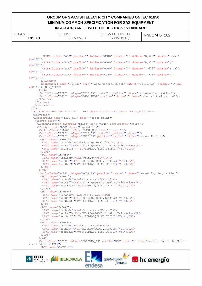
REFERENCE: E3/0001
EDITION: 3 (09.06.10)
SUPERSEDES EDITION: 2 (06.05.10)
PAGE 174 OF 182
GROUP OF SPANISH ELECTRICITY COMPANIES ON IEC 61850
MINIMUM COMMON SPECIFICATION FOR SAS EQUIPMENT
IN ACCORDANCE WITH THE IEC 61850 STANDARD
<FCDA ldInst="ADQ" prefix="" lnClass="GGIO" lnInst="1" doName="Dps01" daName="stVal"
fc="ST"/>
<FCDA ldInst="ADQ" prefix="" lnClass="GGIO" lnInst="1" doName="Dps01" daName="q"
fc="ST"/>
<FCDA ldInst="ADQ" prefix="" lnClass="GGIO" lnInst="1" doName="Ind02" daName="stVal"
fc="ST"/>
<FCDA ldInst="ADQ" prefix="" lnClass="GGIO" lnInst="1" doName="Ind02" daName="q"
fc="ST"/>
</DataSet>
<GSEControl name="CBIED1" desc="Goose Control Block" datSet="DSIED1Goo" confRev="1" ap-
pID="IED1_GOO_APP"/>
</LN0>
<LN lnClass="LPHD" lnType="LPHD_E3" inst="1" prefix="" desc="hardware information"/>
<LN lnClass="GGIO" lnType="GGIO_IED1" prefix="" inst="1" desc="input virtualization"/>
</LDevice>
</Server>
</AccessPoint>
</IED>
<IED name="IED2" desc="Subscriptor" type="" manufacturer="" configVersion="">
<Services/>
<AccessPoint name="IED2_AP1" desc="Access point">
<Server desc="">
<Authentication password="false" none="true" certificate="false"/>
<LDevice inst="ADQ" desc="Adquisition">
<LN0 lnClass="LLN0" lnType="LLN0_E3" inst="" desc=""/>
<LN lnClass="LPHD" lnType="LPHD_E3" inst="1" prefix="" desc=""/>
<LN lnClass="RBRF" lnType="RBRF_E3" prefix="" inst="1" desc="Breaker Failure">
<DOI name="InRef1">
<DAI name="intAddr"><Val>OpEx.general</Val></DAI>
<DAI name="setRef"><Val>IED1ADQ/GGIO1.Ind01.stVal</Val></DAI>
<DAI name="setSrcCB"><Val>IED1ADQ/LLN0.CBIED1</Val></DAI>
</DOI>
<DOI name="InRef2">
<DAI name="intAddr"><Val>OpEx.q</Val></DAI>
<DAI name="setRef"><Val>IED1ADQ/GGIO1.Ind01.q</Val></DAI>
<DAI name="setSrcCB"><Val>IED1ADQ/LLN0.CBIED1</Val></DAI>
</DOI>
</LN>
<LN lnClass="XCBR" lnType="XCBR_E3" prefix="" inst="1" desc="Breaker 2-pole position">
<DOI name="InRef1">
<DAI name="intAddr"><Val>Pos.stVal</Val></DAI>
<DAI name="setRef"><Val>IED1ADQ/GGIO1.Dps01.stVal</Val></DAI>
<DAI name="setSrcCB"><Val>IED1ADQ/LLN0.CBIED1</Val></DAI>
</DOI>
<DOI name="InRef2">
<DAI name="intAddr"><Val>Pos.q</Val></DAI>
<DAI name="setRef"><Val>IED1ADQ/GGIO1.Dps01.q</Val></DAI>
<DAI name="setSrcCB"><Val>IED1ADQ/LLN0.CBIED1</Val></DAI>
</DOI>
<DOI name="InRef3">
<DAI name="intAddr"><Val>Loc.stVal</Val></DAI>
<DAI name="setRef"><Val>IED1ADQ/GGIO1.Ind02.stVal</Val></DAI>
<DAI name="setSrcCB"><Val>IED1ADQ/LLN0.CBIED1</Val></DAI>
</DOI>
<DOI name="InRef4">
<DAI name="intAddr"><Val>Loc.q</Val></DAI>
<DAI name="setRef"><Val>IED1ADQ/GGIO1.Ind02.q</Val></DAI>
<DAI name="setSrcCB"><Val>IED1ADQ/LLN0.CBIED1</Val></DAI>
</DOI>
</LN>
<LN lnClass="GGIO" lnType="GOSGGIO_E3" prefix="GOS" inst="1" desc="Monitoring of the Goose
received from IED1">
<DOI name="GoCBRef">

REFERENCE: E3/0001
EDITION: 3 (09.06.10)
SUPERSEDES EDITION: 2 (06.05.10)
PAGE 175 OF 182
GROUP OF SPANISH ELECTRICITY COMPANIES ON IEC 61850
MINIMUM COMMON SPECIFICATION FOR SAS EQUIPMENT
IN ACCORDANCE WITH THE IEC 61850 STANDARD
<DAI name="setRef"><Val>IED1ADQ/LLN0.CBIED1</Val></DAI>
</DOI>
</LN>
</LDevice>
</Server>
</AccessPoint>
</IED>
<DataTypeTemplates>
<LNodeType id="GGIO_IED1" lnClass="GGIO">
<DO name="Mod" type="INC_E3"/>
<DO name="Beh" type="BEH_INS_E3"/>
<DO name="Health" type="HEALTH_INS_E3"/>
<DO name="NamPlt" type="LPL_E3"/>
<DO name="Ind01" type="SPS_E3"/>
<DO name="Dps01" type="DPS_E3"/>
<DO name="Ind02" type="SPS_E3"/>
</LNodeType>
<LNodeType id="GOSGGIO_E3" lnClass="GGIO">
<DO name="Mod" type="INC_E3"/>
<DO name="Beh" type="BEH_INS_E3"/>
<DO name="Health" type="HEALTH_INS_E3"/>
<DO name="NamPlt" type="LPL_E3"/>
<DO name="St" type="SPS_E3"/>
<DO name="GoCBRef" type="ORG_E3"/>
</LNodeType>
<DOType cdc="ORG" desc="" id="ORG_E3" iedType="">
<DA bType="VisString255" fc="SP" name="intAddr"/>
<DA bType="VisString255" fc="SP" name="setRef"/>
<DA bType="VisString255" fc="SP" name="setSrcCB"/>
<DA bType="VisString255" fc="DC" name="d"/>
</DOType>
</DataTypeTemplates>
</SCL>
REFERENCE: E3/0001
EDITION: 3 (09.06.10)
SUPERSEDES EDITION: 2 (06.05.10)
PAGE 176 OF 182
GROUP OF SPANISH ELECTRICITY COMPANIES ON IEC 61850
MINIMUM COMMON SPECIFICATION FOR SAS EQUIPMENT
IN ACCORDANCE WITH THE IEC 61850 STANDARD
E. ANNEX: (INFORMATIVE) ASCII MIRRORED VIEW OF A SOE LOG As defined in 6.4.2 of this document, a readable mirror of the SOE log will be required as a file in order to download it from the IED. In spite of being outside the scope of the standard, this annex is a proposal of such readable text file.
E.1 General format The mirrored view of the SOE log will be an ASCII text file, with fixed-length fields, in order to easily read the information. Every line will represent a log entry, and each line will have the following ordered fixed-length fields:
1) ‘EntryTime’ field of the log entry.
2) ‘EntryID’ field of the log entry.
3) IEC 61850 reference of the attribute associated to the log entry.
4) Value of the attribute associated to the log entry (‘stVal’ or equivalent).
5) Quality information, based on ‘q’ DA.
6) Date and time with their quality information (based on ‘t’ DA).
7) Description of the data object (based on ‘d’ DA).
In the following clauses, all fields will be specified.
E.1.1 Field #1: EntryTime This field will represent the ‘EntryTime’ attribute of the log entry. The length of this field is 26 ASCII characters and it will have the following format: *#yyyy/mm/dd hh:mm:ss.ccc
Where,
* if ‘ClockFailure’ bit is set, space character instead.
# if ‘ClockNotSynchronized’ bit is set, space character instead.
yyyy/mm/dd hh:mm:ss.ccc the local date and time.
E.1.2 Field #2: EntryID
REFERENCE: E3/0001
EDITION: 3 (09.06.10)
SUPERSEDES EDITION: 2 (06.05.10)
PAGE 177 OF 182
GROUP OF SPANISH ELECTRICITY COMPANIES ON IEC 61850
MINIMUM COMMON SPECIFICATION FOR SAS EQUIPMENT
IN ACCORDANCE WITH THE IEC 61850 STANDARD
This field will represent the ‘EntryID’ attribute of the log entry, The length will be 16 characters, in decimal format, as defined in IEC 61850-6, Table 42 – Data type mapping.
E.1.3 Field #3: IEC 61850 Reference This field will have a length of 255 ASCII characters with the following format constructed from the FCDA entry of the log dataset: LDName/[prefix][LNClass][instance].[DOName].[DAName]
The field ‘.[DAName]’ is optional and depends on whether it appears in the FCDA.
E.1.4 Field #4: Value This field will have a length of 20 ASCII characters. The format will be as follows:
1) If the ‘d’ DA (FC = DC) is not structured, or if no ‘d’ DA exists:
Enum values will be represented according to the DataTypeTemplates section of the CID of the IED.
Other values will be converted to ASCII representation as defined in IEC 61850-6, Table 42 – Data type mapping.
2) If the ‘d’ DA is structured, then tag values ‘A0’, ‘A1’, ‘A2’, ‘A3’, and so on will be used to represent the value of this field.
See section E.2 for information about ‘d’ structured DA.
E.1.5 Field #5: Quality This field will have a length of 29 ASCII characters with the following format: Z(…)PTB
Where,
Field Description
REFERENCE: E3/0001
EDITION: 3 (09.06.10)
SUPERSEDES EDITION: 2 (06.05.10)
PAGE 178 OF 182
GROUP OF SPANISH ELECTRICITY COMPANIES ON IEC 61850
MINIMUM COMMON SPECIFICATION FOR SAS EQUIPMENT
IN ACCORDANCE WITH THE IEC 61850 STANDARD
Z ‘validity’ attribute. It can be the following values:
G for ‘good’ value
I for ‘invalid’ value
R for ‘reserved’ value
Q for ‘questionable’ value
(…) ‘detailQual’ attribute. For every bit active in this attribute, a two ASCII character will be used to represent it. A comma will be used as separator. The following format applies: OV for ‘overflow’ detailQual bit
OR for ‘outOfRange’ detailQual bit
BR for ‘badReference’ detailQual bit
OS for ‘oscillatory’ detailQual bit
FL for ‘failure’ detailQual bit
OD for ‘oldData’ detailQual bit
ER for ‘inconsistent’ detailQual bit
IN for ‘inaccurate’ detailQual bit
Example: (OV,FL,IN) P ‘source’ attribute. It can be ‘P’ for ‘process’ or ‘S’ for ‘substituted’. T ‘test’ attribute. It can be ‘T’ for ‘true’ or space character for ‘false’. B ‘operatorBlocked‘ attribute. It can be ‘B’ for ‘true’ or space character
for ‘false’.
E.1.6 Field #6: Date and time with its quality information This field will be a mirror view of the ‘t’ attribute. If no ‘t’ attribute is present in the DA associated with the log entry, then the ‘EntryTime’ field will be used. The length of this field is 26 ASCII characters and it will have the following format: *#yyyy/mm/dd hh:mm:ss.ccc
Where,
* if ‘ClockFailure’ bit is set, space character instead.
# if ‘ClockNotSynchronized’ bit is set, space character instead.
yyyy/mm/dd hh:mm:ss.ccc the local date and time.
E.1.7 Field #7: Description This field will be a portion of the ‘d’ DA. If no ‘d’ DA belongs to the attribute that the log
REFERENCE: E3/0001
EDITION: 3 (09.06.10)
SUPERSEDES EDITION: 2 (06.05.10)
PAGE 179 OF 182
GROUP OF SPANISH ELECTRICITY COMPANIES ON IEC 61850
MINIMUM COMMON SPECIFICATION FOR SAS EQUIPMENT
IN ACCORDANCE WITH THE IEC 61850 STANDARD
entry is related to, then this field will be filled with space characters. The length of the field will be 60 ASCII characters, and if the ‘d’ DA exists, then the format will be as follows:
1) If the ‘d’ DA is structured, then the tag ‘D’ value of the data attribute will be used to represent this field.
2) If the ‘d’ DA is not structured, then the first 60 ASCII characters will be used to represent this field.
See section E.2 for information about ‘d’ structured data attribute.
E.2 The ‘d’ structured data attribute The ‘d’ DA is called structured if it contains a simple tagged information that is used for several purposes. Every tag is followed by a colon (‘:’) and a text value. The semicolon (‘;’) character is used to separate two consecutive tags. For example, a structured value of a specific ‘d’ DA is the following: ‘D:POSITION;A1:OPEN;A2:CLOSED;A3:DISCORDANCE;A0:UNKNOWN’
Usually, this kind of ‘d’ DA will be used when it is related to a ‘stVal’ DA or equivalent. The following table summarizes the tags that will be used:
TAG DESCRIPTION
D General text for descriptive field. The colon or semicolon character are not allowed.
A0 The text describing the value of 0 of the ‘stVal’ related to.
A1 The text describing the value of 1 of the ‘stVal’ related to.
A2 The text describing the value of 2 of the ‘stVal’ related to.
A3 The text describing the value of 3 of the ‘stVal’ related to.

REFERENCE: E3/0001
EDITION: 3 (09.06.10)
SUPERSEDES EDITION: 2 (06.05.10)
PAGE 180 OF 182
GROUP OF SPANISH ELECTRICITY COMPANIES ON IEC 61850
MINIMUM COMMON SPECIFICATION FOR SAS EQUIPMENT
IN ACCORDANCE WITH THE IEC 61850 STANDARD
F. ANNEX: MODIFIABLE PARAMETERS FOR CONTROLLING AN IED´S BEHAVIOUR WITH RESPECT TO CID LOADING, VALIDATION AND ACTIVATION
The following data objects (in red color in the next table) shall be added to the LPHD logical node of the IED. If several LPHD logical nodes exist, because the IED contains several logical devices, then these data objects shall be placed in the LPHD logical node of that logical device which is fundamentally oriented to control functions.
See 6.2.3 and 6.2.4 for a detailed description of the values of these data objects and their meanings.
LPHD class
Data Name Comon Data
Class Explanation T M/O/C
LLName Shall be inherited from Logical-Node Class (see IEC 61850-7-2)
Data
PhyNam DPL Physical device name plate M
PhyHealth INS Physical device health M
OutOv SPS Output communications buffer overflow O
Proxy SPS Indicates if this LN is a proxy M
InOv SPS Input communications buffer overflow O
NumPwrUp INS Number of Opwer ups O
WrmStr INS Number of Warm Starts O
WacTrg INS Number of watchdog device resets detected O
PwrUp SPS Power Up detected O
PwrDn SPS Power Down detected O
PwrSupAlm SPS External power supply alarm O
RsStat SPC Reset device statistics T O
LoadMod ING Behavior with respect to CID loading. 1- Indifferent mode 2- Protected mode 3- Upload mode NOTE: The change from protected mode to upload mode shall not be pos-sible through the ACSI services. It shall only be possible by means of the IED’s physical interface, if such exists.
ME
ValActAuto SPG Behavior with respect to CID validation and activation. 0 - Controlled mode 1 - Automatic mode
ME

REFERENCE: E3/0001
EDITION: 3 (09.06.10)
SUPERSEDES EDITION: 2 (06.05.10)
PAGE 181 OF 182
GROUP OF SPANISH ELECTRICITY COMPANIES ON IEC 61850
MINIMUM COMMON SPECIFICATION FOR SAS EQUIPMENT
IN ACCORDANCE WITH THE IEC 61850 STANDARD
Data Sets (see IEC 61850-7-2)
Inherited and specialised from Logical Node class (see IEC 61850-7-2)
Control Blocks (see IEC 61850-7-2)
Inherited and specialised from Logical Node class (see IEC 61850-7-2)
Services (see IEC 61850-7-2)
Inherited and specialised from Logical Node class (see IEC 61850-7-2)
Note: ‘ME’ means ‘mandatory by extension’.

REFERENCE: E3/0001
EDITION: 3 (09.06.10)
SUPERSEDES EDITION: 2 (06.05.10)
PAGE 182 OF 182
GROUP OF SPANISH ELECTRICITY COMPANIES ON IEC 61850
MINIMUM COMMON SPECIFICATION FOR SAS EQUIPMENT
IN ACCORDANCE WITH THE IEC 61850 STANDARD
G. ANNEX: CONVENTIONAL INPUTS AND OUTPUTS Binary inputs and outputs In an ideal IEC 61850 SAS, IEDs will have no binary inputs or outputs, with the exception of level-0 IEDs. In real systems, however, these interfaces will continue to be required in the near future. When present, they shall be modeled within the IEC 61850’s data model of the device. An array of binary inputs shall be modeled by a GGIO logical node. Each input status shall be modeled by an ‘Ind’ SPS data object. In a similar way, an array of binary outputs shall be modeled by a GGIO logical node. In addition to the status data, there shall be a controllable data object for each output. In other words, each output status shall be modeled by an ‘SPCSO’ SPC data object. Analog inputs and outputs Analog inputs and outputs, when present, shall be modeled within the IEC 61850’s data model of the device. An array of analog inputs shall be modeled by a GGIO logical node. Each input status shall be modeled by an ‘AnIn’ MV data object. In a similar way, an array of analog outputs shall be modeled by a GGIO logical node. Each input status shall be modeled by an ‘AnOut’ APC data object.