growth of cnts over fe co/nanometric tio2 catalyst by...
TRANSCRIPT

Int. J. Nanosci. Nanotechnol., Vol. 13, No. 1, March. 2017, pp. 1-9
1
Growth of CNTs over Fe–Co/Nanometric TiO2
Catalyst by CVD: The Effects of Catalyst
Composition and Growth Temperature
Z. S. Arabshahi1, M. Akbarzadeh Pasha1,2* and F. Shahi1
1Department of Solid State Physics, Faculty of Basic Science, University of Mazandaran,
P. O. Box 47416-95447, Babolsar, Iran 2Research lab of Carbon-based nanostructures, Faculty of Basic Science, University of
Mazandaran, Babolsar, Iran
(*) Corresponding author: [email protected] (Received: 02 March 2015 and Accepted: 17 August 2016)
Abstract In this research carbon nanotubes were produced by chemical vapor deposition of acetylene over a
mixture of iron and cobalt catalysts supported on nanometric TiO2 and the influences of two synthesis
parameters: growth temperature and catalyst composition ratio on properties of end-product carbon
nanotubes were investigated. The catalytic basis was prepared by wet impregnation method with
different wt% mass ratio of Fe-Co/TiO2=20-0/80, 15-5/80, 10-10/80, 5-15/80 and 0-20/80 wt%. The
nanomaterials (catalysts and carbon nanotubes) were characterized using X-ray diffraction (XRD), field
emission scanning electron microscopy (FESEM), X-ray map of elemental distribution (Xmap) and
Raman spectroscopy. The results confirmed that by increasing the growth temperature from 650°C to
800°C; the growth rate, the average diameter and the amount of impurities of grown carbon nanotubes
increase and their length and density decrease. Furthermore, it was observed that in comparison with
monometallic Fe or Co, bimetallic compositions of these metals exhibit better catalytic activity in growth
of carbon nanotubes. The highest yield of carbon nanotubes possessing minimum average diameter was
obtained on Fe-Co/TiO2 catalyst with a mass ratio of 10-10/80 wt%.
Keywords: Carbon Nanotubes, Wet Impregnation, Chemical Vapor Deposition, TiO2
Nanopowder, Bimetallic Catalyst Composition.
1. INRODUCTION
Carbon nanotubes (CNTs) are seamless
coaxial cylinders of one or several
graphene sheets denoted by single wall
carbon nanotubes, SWCNTs, or Multiwall
carbon nanotubes, MWCNTs [1]. Due to
their remarkable mechanical, structural,
electronic, electromechanical and chemical
properties [2, 3], CNTs are considered to
be excellent candidates for many potential
applications such as nanocomposite
materials, sensors and actuators, catalyst
and catalyst supports, field emitters, tips
for scanning probe microscopy, energy
storage devices, nanoelectronics, bio-
nanomaterials and nanomedicine,
hydrogen storage and fuel cell [4-12].
CNTs are generally synthesized by three
major methods including arc-discharge
[13], laser ablation [14] and chemical
vapour deposition (CVD) [15-20]. Among
these, CVD has attracted much attention
owing to its advantages such as simplicity,
high purity, high yield, selective, scalable
and cost-effective growth of CNTs [18-
20]. The CVD growth of CNTs is a
catalytic reaction. Researchers have shown
that monometallic or bimetallic
combination of iron group metals, i.e. Fe,
Co and Ni or addition of other metals to
them as co-catalysts including Mo, Mg,
Mn, Cr and Pd can catalyze CNTs from
decomposition of different hydrocarbon
gases via CVD [16, 18, 19, 21-26]. It is
widely reported that various parameters
2 Arabshahi, Akbarzadeh Pasha and Shahi
comprising of the type and composition of
catalyst, the preparation method and pre-
treatment of catalyst, type of catalyst
support or substrate, kind and flow of
hydrocarbon source, the growth
temperature and growth time can deeply
influence the structural features of CNTs
such as their diameter and length,
morphology, thermal stability, crystallinity
and growth yield [16, 18, 19, 24, 27-36].
Kathyayini et al. examined the catalytic
activity of Fe, Co and Fe/Co supported on
Ca and Mg oxides, hydroxides and
carbonates in the synthesis of CNTs via
thermal CVD (TCVD) [37]. The catalyst-
support mixtures were prepared by wet
impregnation method. Acetylene and
ethylene were used as the two different
carbon sources and N2 as the carrier gas
and the synthesis reactions were conducted
at 700°C. They observed that irrespective
of applied support, the best yield of carbon
deposit was obtained for mixture of Fe and
Co compared to monometallic catalysts.
Furthermore they found that calcium
carbonate and magnesium oxide are the
best supports among the six compositions
of Ca and Mg. Pudukudy et al. reported
direct decomposition of methane to COx-
free hydrogen and CNTs over SBA-
15(highly ordered mesoporous silicate)
supported Ni, Co and Fe based bimetallic
catalysts [38]. They concluded that the
SBA-15 supported bimetallic catalysts
have key role on formation of open tip
CNTs. This work aims to study the
variation of CNTs characteristics including
mean diameter, growth rate, quality and
density of growth at different temperatures
ranging from 650°C to 800°C by CVD of
acetylene, over bimetallic Fe-Co catalysts
with different mass ratios supported on
nanomeric TiO2. TiO2 is a well-known
semiconductor material and combination
of CNT with TiO2 nanoparticles may lead
to new potential application in
photocatalysis [39, 40].
2. MATERIALS AND METHODS
2.1. Preparation of the Catalysts
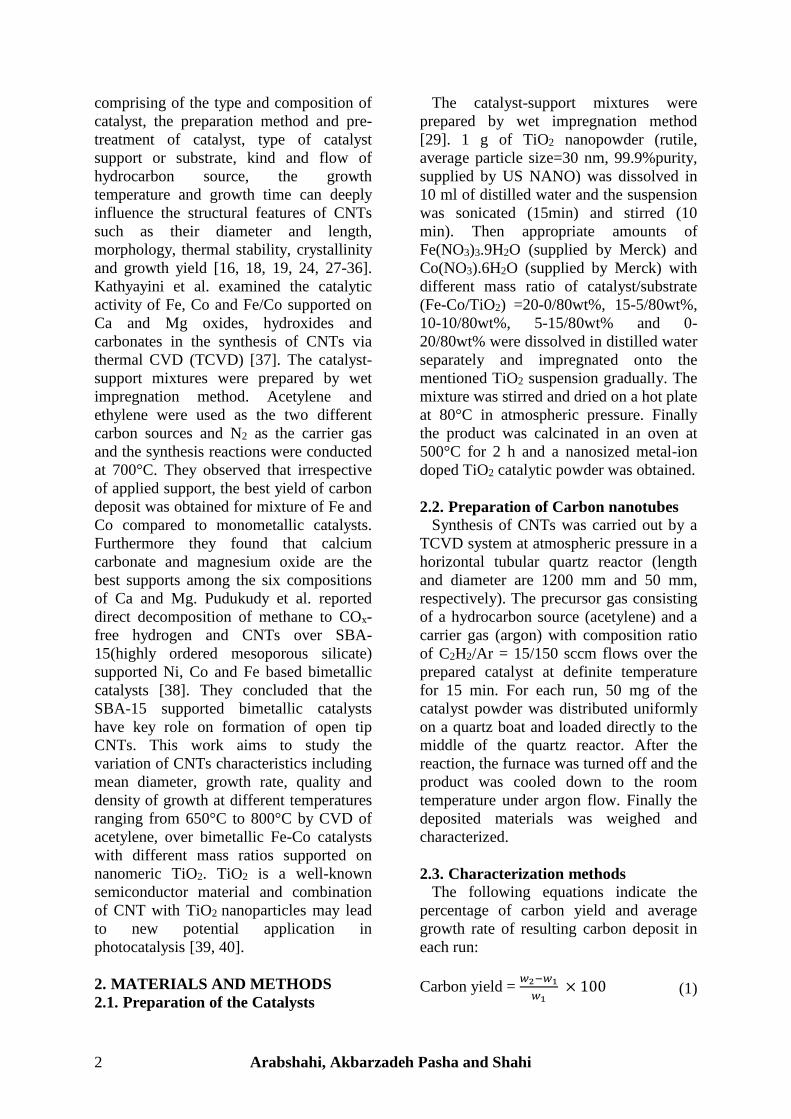
The catalyst-support mixtures were
prepared by wet impregnation method
[29]. 1 g of TiO2 nanopowder (rutile,
average particle size=30 nm, 99.9%purity,
supplied by US NANO) was dissolved in
10 ml of distilled water and the suspension
was sonicated (15min) and stirred (10
min). Then appropriate amounts of
Fe(NO3)3.9H2O (supplied by Merck) and
Co(NO3).6H2O (supplied by Merck) with
different mass ratio of catalyst/substrate
(Fe-Co/TiO2) =20-0/80wt%, 15-5/80wt%,
10-10/80wt%, 5-15/80wt% and 0-
20/80wt% were dissolved in distilled water
separately and impregnated onto the
mentioned TiO2 suspension gradually. The
mixture was stirred and dried on a hot plate
at 80°C in atmospheric pressure. Finally
the product was calcinated in an oven at
500°C for 2 h and a nanosized metal-ion
doped TiO2 catalytic powder was obtained.
2.2. Preparation of Carbon nanotubes
Synthesis of CNTs was carried out by a
TCVD system at atmospheric pressure in a
horizontal tubular quartz reactor (length
and diameter are 1200 mm and 50 mm,
respectively). The precursor gas consisting
of a hydrocarbon source (acetylene) and a
carrier gas (argon) with composition ratio
of C2H2/Ar = 15/150 sccm flows over the
prepared catalyst at definite temperature
for 15 min. For each run, 50 mg of the
catalyst powder was distributed uniformly
on a quartz boat and loaded directly to the
middle of the quartz reactor. After the
reaction, the furnace was turned off and the
product was cooled down to the room
temperature under argon flow. Finally the
deposited materials was weighed and
characterized.
2.3. Characterization methods
The following equations indicate the
percentage of carbon yield and average
growth rate of resulting carbon deposit in
each run:
Carbon yield = 𝑤2−𝑤1
𝑤1 × 100 (1)

International Journal of Nanoscience and Nanotechnology 3
Ave. growth rate = 𝑤2−𝑤1
𝑔𝑟𝑜𝑤𝑡ℎ 𝑡𝑖𝑚𝑒 (
𝑚𝑔
𝑚𝑖𝑛 ) (2)
Where 𝑤2 is the total mass of final
product, catalyst and carbon deposit, and
𝑤1 is the initial mass of catalyst. The
morphology and microstructure of
resulting catalytic powders and CNTs were
characterized by Field Emission Scanning
Electron Microscopy (FESEM, MIRA\\
TESCAN). To determine the crystalline
structure and average size of catalyst
nanoparticles, the X-ray diffraction pattern
(XRD, Bruker AXS, D8- Advance, Cu–Kα,
λ= 1.54 Å) was used. The approximate
sizes of metal oxide particles were
calculated by the Scherrer equation:
D = 𝐾𝜆
𝛽 𝐶𝑜𝑠 𝜃 (3)
Where D is the size of particle, λ= 1.54 Å
is the X ray wavelength, is the diffraction
angle, k=0.89 is the shape factor and β is
the FWHM of the peak (full width at half
maximum). The crystallization and quality
of CNTs was investigated using Micro-
Raman spectroscopy (SENTERRA
BRUKER, λ= 785nm).
3. RESULTS AND DISCUSSION
3.1. The Effect of Catalyst Composition
In order to examine the effect of catalyst
composition on properties of end-product
CNTs, different catalyst samples with
different mass ratios of catalyst/substrate
(Fe-Co/TiO2) =20-0/80 wt%, 15-5/80 wt%,
10-10/80 wt%, 5-15/80 wt% and 0-20/80
wt% were prepared and used for synthesis
of carbon nanotubes at temperature of
700°C. Crystalline structures of the
catalysts were characterized by XRD.
The diffraction patterns are shown in
Figure 1. The most intense peaks in Figure
1 correspond to the rutile phase of TiO2
support which are observed for all
compositions of the catalysts at 2 = 27.5°,
36.1°, 39.2°, 41.3°, 44°, 54.3°, 56.7°,
62.8°, 64°, 69.1° and 70°. Beside the
support’s peaks, the metal oxides peaks
were also observed in the catalysts. The
peaks at 2 = 24.2°, 33.2°, 36.1°, 41°,
49.5°, 57.8°, 62.8°, 64.1° and 72° in Figure
1 (a) to (d) indicate the presence of Fe2O3
particles and the peaks at 2 = 31.3°,
36.9°, 38.5°, 44.9°, 59.4° and 65.3° in
Figure 1 (b) to (d), correspond to the
Co3O4 particles. Furthermore the XRD
patterns show that when the amount of
metal salts increases the intensity of the
corresponding peaks (related metal oxides)
increases as well. The approximate sizes of
crystallites were calculated using Scherer
equation (equation (3)) and shown in Table
1. The approximate sizes of catalyst
nanoparticles on different catalyst
compositions are nearly similar. It seems
that bimetallic composition of Fe and Co
lead to smaller particles compared to
monometallic ones.
Figure 2 (a) to (e) shows the typical
FESEM images of the five catalyst
samples. These images exhibit the granular
and nanometric structure of different
compositions of Fe-Co/TiO2 catalyst
samples. The morphologies of the five
compositions of catalysts are nearly
similar. The distribution of particles on
catalyst-support matrix is relatively
uniform and the particles have rather
spherical shapes. It seems that bimetallic
catalyst samples (Fig.2 (b), (c) and (d))
possess smaller particles and finer
Figure 1. XRD patterns of the Fe-Co/TiO2
catalysts with different wt% mass ratios, a)
20-0/80, b) 15-5/80, c) 10-10/80, d) 5-
15/80, e) 0-20/80.
4 Arabshahi, Akbarzadeh Pasha and Shahi
structures compared to monometallic ones
(Figure 2(a) and (e)).
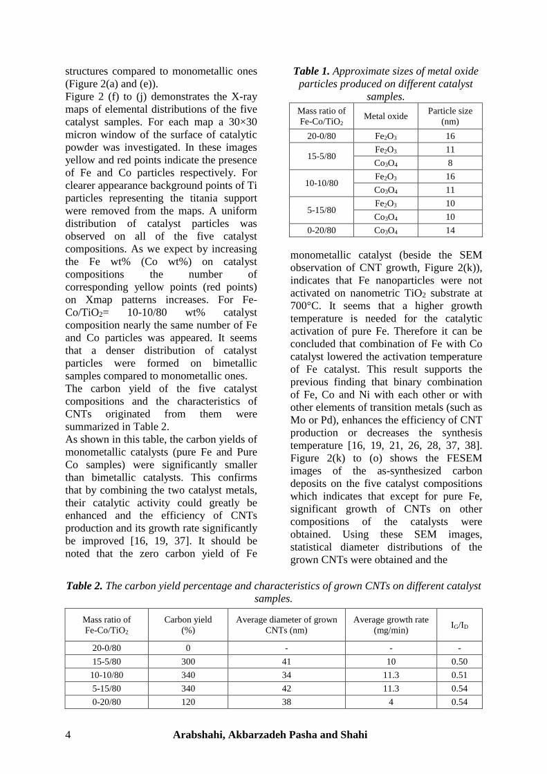
Figure 2 (f) to (j) demonstrates the X-ray
maps of elemental distributions of the five
catalyst samples. For each map a 30×30
micron window of the surface of catalytic
powder was investigated. In these images
yellow and red points indicate the presence
of Fe and Co particles respectively. For
clearer appearance background points of Ti
particles representing the titania support
were removed from the maps. A uniform
distribution of catalyst particles was
observed on all of the five catalyst
compositions. As we expect by increasing
the Fe wt% (Co wt%) on catalyst
compositions the number of
corresponding yellow points (red points)
on Xmap patterns increases. For Fe-
Co/TiO2= 10-10/80 wt% catalyst
composition nearly the same number of Fe
and Co particles was appeared. It seems
that a denser distribution of catalyst
particles were formed on bimetallic
samples compared to monometallic ones.
The carbon yield of the five catalyst
compositions and the characteristics of
CNTs originated from them were
summarized in Table 2.
As shown in this table, the carbon yields of
monometallic catalysts (pure Fe and Pure
Co samples) were significantly smaller
than bimetallic catalysts. This confirms
that by combining the two catalyst metals,
their catalytic activity could greatly be
enhanced and the efficiency of CNTs
production and its growth rate significantly
be improved [16, 19, 37]. It should be
noted that the zero carbon yield of Fe
monometallic catalyst (beside the SEM
observation of CNT growth, Figure 2(k)),
indicates that Fe nanoparticles were not
activated on nanometric TiO2 substrate at
700°C. It seems that a higher growth
temperature is needed for the catalytic
activation of pure Fe. Therefore it can be
concluded that combination of Fe with Co
catalyst lowered the activation temperature
of Fe catalyst. This result supports the
previous finding that binary combination
of Fe, Co and Ni with each other or with
other elements of transition metals (such as
Mo or Pd), enhances the efficiency of CNT
production or decreases the synthesis
temperature [16, 19, 21, 26, 28, 37, 38].
Figure 2(k) to (o) shows the FESEM
images of the as-synthesized carbon
deposits on the five catalyst compositions
which indicates that except for pure Fe,
significant growth of CNTs on other
compositions of the catalysts were
obtained. Using these SEM images,
statistical diameter distributions of the
grown CNTs were obtained and the
Table 1. Approximate sizes of metal oxide
particles produced on different catalyst
samples.
Mass ratio of
Fe-Co/TiO2 Metal oxide
Particle size
(nm)
20-0/80 Fe2O3 16
15-5/80 Fe2O3 11
Co3O4 8
10-10/80 Fe2O3 16
Co3O4 11
5-15/80 Fe2O3 10
Co3O4 10
0-20/80 Co3O4 14
Table 2. The carbon yield percentage and characteristics of grown CNTs on different catalyst
samples.
Mass ratio of
Fe-Co/TiO2
Carbon yield
(%)
Average diameter of grown
CNTs (nm)
Average growth rate
(mg/min) IG/ID
20-0/80 0 - - -
15-5/80 300 41 10 0.50
10-10/80 340 34 11.3 0.51
5-15/80 340 42 11.3 0.54
0-20/80 120 38 4 0.54

International Journal of Nanoscience and Nanotechnology 5
Figure 2. FESEM images of catalyst basis with wt% of Fe-Co/TiO2 : a) 20-0/80, b) 15-5/80,
c) 10-10/80, d) 5-15/80 and e) 0-20/80. Xmap images of catalyst basis with wt% of Fe-
Co/TiO2 : f) 20-0/80, g) 15-5/80, h) 10-10/80, i) 5-15/80 and j) 0-20/80. FESEM images of
grown CNTs on different catalysts basis with wt% of Fe-Co/TiO2 : k) 20-0/80, l) 15-5/80, m)
10-10/80, n) 5-15/80 and o) 0-20/80.
6 Arabshahi, Akbarzadeh Pasha and Shahi
average diameters of the nanotubes were
calculated and presented in Table 2. Our
observations show that the best catalyst
composition for CNT production is Fe-
Co/TiO2=10-10/80 wt%, because this
composition led to maximum abundance of
CNTs with minimum average diameter.
Furthermore, it can be concluded that the
addition of Fe particles to pure Co catalyst
has beneficial result. At the critical mass
ratio of Fe-Co/ TiO2=10-10/80 wt%, the
best catalytic activity is obtained. After
this critical point, addition of more Fe
content may lead to destructive results.
In order to investigate the crystallinity of
the grown CNTs, Raman spectroscopy was
executed. Figure 3 represents the Raman
spectra of the grown CNTs on different
catalyst samples. The Raman band
appearing in 1500-1605 cm-1 region of the
wave number is ascribed to G band
(graphite band) and the one appearing in
1250-1450 cm-1 spectral region is known
as D band (disorder-induced band). The G
band is assigned to C-C vibration
frequency of the carbon material with sp2
orbital structure and the D band
contributed to disorder-induced vibration
of C-C band [41]. According to Figure 3,
two peaks corresponding to the D and G
bands of MWCNTs appeared in each
spectrum. The intensity ratio of G to D
band, IG/ID is known as a rough measure
for the quality of produced CNTs. This
parameter was calculated from Raman
analysis and shown in Table 2.
Considering this Table, it can be concluded
that in bimetallic catalysts with increasing
Co content, the quality and order of
crystallinity of grown CNTs were slightly
improved. This result confirms the
previous reports that the catalytic activity
of iron nanoparticles is higher than cobalt
ones. However the quality and order of
crystallinity of the nanotubes in the
vicinity of Fe catalyst is lower than Co
[16].
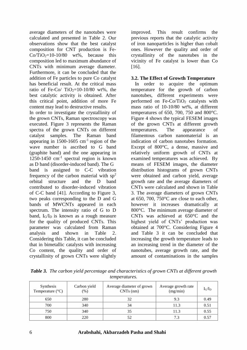
3.2. The Effect of Growth Temperature
In order to acquire the optimum
temperature for the growth of carbon
nanotubes, different experiments were
performed on Fe-Co/TiO2 catalysts with
mass ratio of 10-10/80 wt%, at different
temperatures of 650, 700, 750 and 800°C.
Figure 4 shows the typical FESEM images
of the grown CNTs at different growth
temperatures. The appearance of
filamentous carbon nanomaterial is an
indication of carbon nanotubes formation.
Except of 800°C, a dense, massive and
relatively uniform growth of CNTs at
examined temperatures was achieved. By
means of FESEM images, the diameter
distribution histograms of grown CNTs
were obtained and carbon yield, average
growth rate and the average diameters of
CNTs were calculated and shown in Table
3. The average diameters of grown CNTs
at 650, 700, 750°C are close to each other,
however it increases dramatically at
800°C. The minimum average diameter of
CNTs was achieved at 650°C and the
highest yield of CNTs’ production was
obtained at 700°C. Considering Figure 4
and Table 3 it can be concluded that
increasing the growth temperature leads to
an increasing trend in the diameter of the
nanotubes, average growth rate, and the
amount of contaminations in the samples
Table 3. The carbon yield percentage and characteristics of grown CNTs at different growth
temperatures.
Synthesis
Temperature (°C)
Carbon yield
(%)
Average diameter of grown
CNTs (nm)
Average growth rate
(mg/min) IG/ID
650 280 32 9.3 0.49
700 340 34 11.3 0.51
750 340 35 11.3 0.55
800 220 52 7.3 0.57

International Journal of Nanoscience and Nanotechnology 7
along with a reduction in the length and
density of CNTs. The CNTs with larger
diameter and lower density are grown by
raising the growth temperature. Increasing
the growth temperature may lead to
agglomeration of catalyst particles, so at
higher temperature, larger catalyst particles
can be formed. It is generally accepted that
the sizes of catalyst particles usually
determine the diameters of CNTs in CVD
approach [16, 19, 42]. On the other hand,
increasing the growth temperature, results
in more impurities in the final product
which may also relate to formation of
larger catalyst particles at higher
temperatures. These larger catalyst
particles have lower catalytic activities
which may cause to formation of
amorphous carbon [27]. Figure 5
represents Raman spectra of the grown
CNTs at different growth temperatures.
The IG/ID ratios of the grown CNTs were
calculated using these spectra and shown
in Table 3. Raman spectroscopy indicated
that increasing the growth temperature
gradually improves the quality of produced
CNTs, which is in accordance with the
finding of other researchers [27, 43].
4. CONCLUSIONS
In summary, we have successfully grown
CNTs on a wet impregnation prepared
mixture of iron and cobalt nanoparticles
supported on TiO2 substrate from
decomposing of acetylene by TCVD in the
temperature range of 650-800°C. It was
observed that the growth rate, diameter and
crystallinity of CNTs can be controlled by
adjusting the growth temperature. With
increasing the temperature from 650°C to
800°C, the growth rate, average diameter,
and the amount of impurities increase
along with reduction in the length and
Figure 3. Raman spectrum of the grown
CNTs at different wt% mass ratios of Fe-
Co/TiO2, a) 15-5/80, b) 10-10/80, c) 5-
15/80 and d) 0-20/80.
Figure 4. SEM images of the CNTs grown
on Fe-Co/TiO2=10-10/80 wt% catalyst at
a) 650°C, b) 700°C, c) 750°C, d) 800°C.

8 Arabshahi, Akbarzadeh Pasha and Shahi
density of CNTs. In addition, CNTs were
synthesized on different composition of
monometallic and bimetallic Fe and Co
catalysts which further proves that the
carbon yield of the catalyst and its activity,
the average diameter of end-product CNTs,
and the density of the growth are
significantly influenced by the composition
of the catalyst. No growth of CNTs on
titania supported pure Fe catalyst was
achieved. The growth on binary
combination of Fe and Co was much more
successful than monometallic Co catalyst.
The best catalytic activity and the most
favourable growth of CNTs was obtained
on the catalyst-support composition of Fe-
Co/TiO2 = 10-10/80 %wt.
REFERENCES 1. Iijima, S., (1991). “Helical microtubules of graphitic carbon”, nature, 354: 56-58.
2. Harris, P. J. F., Harris, P. J. F., (2009). “Carbon Nanotube Science: Synthesis, Properties and Applications”,
Cambridge University Press.
3. Popov, V. N., (2004). “Carbon nanotubes: Properties and application”, Mater. Sci. Eng., R, 43: 61-102.
4. De Volder, M. F. L., Tawfick, S. H., Baughman, R. H., Hart, A. J., (2013). “Carbon nanotubes: Present and
future commercial applications”, Science, 339: 535-539.
5. Zhang, Q., (2012). “Carbon Nanotubes and Their Applications”, CRC Press.
6. Tan, C. W., Tan, K. H., Ong, Y. T., Mohamed, A. R., Zein, S. H. S., Tan, S. H., (2012). “Energy and
environmental applications of carbon nanotubes”, Environ. Chem. Lett., 10: 265-273.
7. Verma, P., Saini, P., Malik, R. S., Choudhary, V., (2015). “Excellent electromagnetic interference shielding
and mechanical properties of high loading carbon-nanotubes/polymer composites designed using melt
recirculation equipped twin-screw extruder”, Carbon, 89: 308-317.
8. Cheng, Y., Xu, C., Jia, L., Gale, J. D., Zhang, L., Liu, C., Shen, P. K., Jiang, S. P., (2015). “Pristine carbon
nanotubes as non-metal electrocatalysts for oxygen evolution reaction of water splitting”, Appl. Catal., B,
163: 96-104.
9. Alsawat, M., Altalhi, T., Kumeria, T., Santos, A., Losic, D., (2015). “Carbon nanotube-nanoporous anodic
alumina composite membranes with controllable inner diameters and surface chemistry: Influence on
molecular transport and chemical selectivity”, Carbon, 93: 681-692.
10. Hou, P.-X., Liu, C., Cheng, H.-M., (2008). “Purification of carbon nanotubes”, Carbon, 46: 2003-2025.
11. Hamidi Malayeri, F., Sohrabi, M. R., Ghourchian, H., (2012). “Magnetic multi-walled carbon nanotube as
an adsorbent for toluidine blue O removal from aqueous solution”, Int. J. Nanosci. Nanotechnol., 8: 79-86.
12. Kolangikhah, M., Maghrebi, M., Ghazvini, K., Farhadian, N., (2012). “Separation of salmonella
typhimurium bacteria from water using MWCNTs arrays”, Int. J. Nanosci. Nanotechnol., 8: 3-10.
13. Arora, N., Sharma, N., (2014). “Arc discharge synthesis of carbon nanotubes: Comprehensive review”,
Diamond Relat. Mater., 50: 135-150.
14. Chrzanowska, J., Hoffman, J., Małolepszy, A., Mazurkiewicz, M., Kowalewski, T. A., Szymanski, Z.,
Stobinski, L., (2015). “Synthesis of carbon nanotubes by the laser ablation method: Effect of laser
wavelength”, Phys. Status Solidi B, 252: 1860-1867.
15. Jourdain, V., Bichara, C., (2013). “Current understanding of the growth of carbon nanotubes in catalytic
chemical vapour deposition”, Carbon, 58: 2-39.
16. Dupuis, A.-C., (2005). “The catalyst in the CCVD of carbon nanotubes-a review”, Prog. Mater Sci., 50:
929-961.
17. Yu, Z., Chen, D., Tøtdal, B., Holmen, A., (2005). “Effect of catalyst preparation on the carbon nanotube
growth rate”, Catal. Today, 100: 261-267.
18. Mubarak, N., Abdullah, E., Jayakumar, N., Sahu, J., (2014). “An overview on methods for the production of
carbon nanotubes”, J. Ind. Eng. Chem., 20: 1186-1197.
Figure 5. Raman spectrum of the grown
CNTs on Fe-Co/TiO2=10-10/80 wt%
catalyst at a) 650°C, b) 700°C, c) 750°C,
d) 800°C.
International Journal of Nanoscience and Nanotechnology 9
19. Kumar, M., Ando, Y., (2010). “Chemical vapor deposition of carbon nanotubes: a review on growth
mechanism and mass production”, J. Nanosci. Nanotechnol., 10: 3739-3758.
20. Zhang, Q., Huang, J. Q., Zhao, M. Q., Qian, W. Z., Wei, F., (2011). “Carbon nanotube mass production:
principles and processes”, ChemSusChem., 4: 864-889.
21. Lobiak, E., Shlyakhova, E., Bulusheva, L., Plyusnin, P., Shubin, Y. V., Okotrub, A., (2015). “Ni–Mo and
Co–Mo alloy nanoparticles for catalytic chemical vapor deposition synthesis of carbon nanotubes”, J. Alloys
Compd., 621: 351-356.
22. Takagi, D., Hibino, H., Suzuki, S., Kobayashi, Y., Homma, Y., (2007). “Carbon nanotube growth from
semiconductor nanoparticles”, Nano Lett., 7: 2272-2275.
23. Tan, L.-L., Ong, W.-J., Chai, S.-P., Mohamed, A. R., (2013). “Growth of carbon nanotubes over non-
metallic based catalysts: A review on the recent developments”, Catal. Today, 217: 1-12.
24. Chiang, W.-H., Sankaran, R. M., (2009). “Linking catalyst composition to chirality distributions of as-
grown single-walled carbon nanotubes by tuning NixFe1− x nanoparticles”, Nat. Mater., 8: 882-886.
25. Pasha, M. A., Shafiekhani, A., Vesaghi, M., (2009). “Hot filament CVD of Fe–Cr catalyst for thermal CVD
carbon nanotube growth from liquid petroleum gas”, Appl. Surf. Sci., 256: 1365-1371.
26. Mortazavi, S., Reyhani, A., (2008). “The effect of Pd addition to Fe as catalysts on growth of carbon
nanotubes by TCVD method”, Appl. Surf. Sci., 254: 6416-6421.
27. Pasha, M. A., Poursalehi, R., Vesaghi, M., Shafiekhani, A., (2010). “The effect of temperature on the
TCVD growth of CNTs from LPG over Pd nanoparticles prepared by laser ablation”, Phys. B, 405: 3468-
3474.
28. Shah, K. A., Tali, B. A., (2016). “Synthesis of carbon nanotubes by catalytic chemical vapour deposition: A
review on carbon sources, catalysts and substrates”, Mater. Sci. Semicond. Process, 41: 67-82.
29. Tsoufis, T., Xidas, P., Jankovic, L., Gournis, D., Saranti, A., Bakas, T., Karakassides, M. A., (2007).
“Catalytic production of carbon nanotubes over Fe-Ni bimetallic catalysts supported on MgO”, Diamond
Relat. Mater., 16: 155-160.
30. Huang, Z., Wang, D., Wen, J., Sennett, M., Gibson, H., Ren, Z., (2002). “Effect of nickel, iron and cobalt
on growth of aligned carbon nanotubes”, Appl. Phys. A, 74: 387-391.
31. Harutyunyan, A. R., Pradhan, B. K., Kim, U., Chen, G., Eklund, P., (2002). “CVD synthesis of single wall
carbon nanotubes under “soft” conditions”, Nano Lett., 2: 525-530.
32. Kichambare, P. D., Qian, D., Dickey, E. C., Grimes, C. A., (2002). “Thin film metallic catalyst coatings for
the growth of multiwalled carbon nanotubes by pyrolysis of xylene”, Carbon, 40: 1903-1909.
33. Alvarez, W. E., Kitiyanan, B., Borgna, A., Resasco, D. E., (2001). “Synergism of Co and Mo in the
catalytic production of single-wall carbon nanotubes by decomposition of CO”, Carbon, 39: 547-558.
34. Hernadi, K., Fonseca, A., Nagy, J. B., Siska, A., Kiricsi, I., (2000). “Production of nanotubes by the
catalytic decomposition of different carbon-containing compounds”, Appl. Catal. A, 199: 245-255.
35. Masoumi, M., Mehrnia, M. R., Montazer-Rahmati, M. M., Rashidi, A. M., (2010). “Templated growth of
carbon nanotubes on nickel loaded mesoporous MCM-41 and MCM-48 molecular sieves”, Int. J. Nanosci.
Nanotechnol., 6: 88-96.
36. Jabari Seresht, R., Jahanshahi, M., Raoof, J., Khorram, M., (2009). “Optimization of experimental
conditions for fabrication of carbon nanotubes based on taguchi robust design method”, Int. J. Nanosci.
Nanotechnol., 5: 9-18.
37. Kathyayini, H., Nagaraju, N., Fonseca, A., Nagy, J., (2004). “Catalytic activity of Fe, Co and Fe/Co
supported on Ca and Mg oxides, hydroxides and carbonates in the synthesis of carbon nanotubes”, J. Mol.
Catal. A: Chem., 223: 129-136.
38. Pudukudy, M., Yaakob, Z., Akmal, Z. S., (2015). “Direct decomposition of methane over SBA-15
supported Ni, Co and Fe based bimetallic catalysts”, Appl. Surf. Sci., 330: 418-430.
39. Chen, H., Wang, L., (2014). “Nanostructure sensitization of transition metal oxides for visible-light
photocatalysis”, Beilstein J. Nanotechnol., 5: 696-710.
40. Soroodan Miandoab, E., Fatemi, S., (2014). “Upgrading TiO2 photoactivity under visible light by synthesis
of MWCNT/TiO2 nanocomposite”, Int. J. Nanosci. Nanotechnol., 11: 1-12.
41. Dresselhaus, M. S., Dresselhaus, G., Saito, R., Jorio, A., (2005). “Raman spectroscopy of carbon
nanotubes”, Phys. Rep., 409: 47-99.
42. Lee, C. J., Park, J., Huh, Y., Lee, J. Y., (2001). “Temperature effect on the growth of carbon nanotubes
using thermal chemical vapor deposition”, Chem. Phys. Lett., 343: 33-38.
43. Kim, K.-E., Kim, K.-J., Jung, W. S., Bae, S. Y., Park, J., Choi, J., Choo, J., (2005). “Investigation on the
temperature-dependent growth rate of carbon nanotubes using chemical vapor deposition of ferrocene and
acetylene”, Chem. Phys. Lett., 401: 459-464.