growth of garnet and perovskite scintillators with non...
TRANSCRIPT
Growth of garnet and perovskite
scintillators with non-isovalent minor
components and related effects
A. Petrosyan1, K. Hovhannesyan1, M. Derdzyan1,
A. Yeganyan1, R. Sargsyan1, F. Moretti2, C. Dujardin2
1Institute for Physical Research, National Academy of Sciences, 0203 Ashtarak, Armenia
2Institut Lumière Matière, UMR 5306 Université Lyon 1-CNRS, Villeurbanne,
France
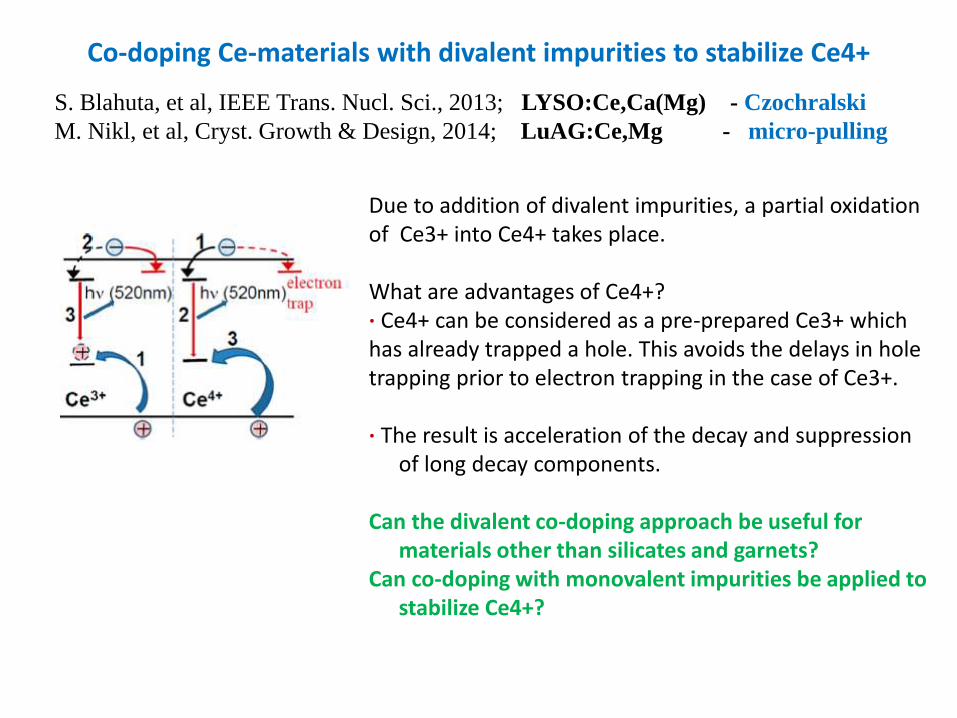
Co-doping Ce-materials with divalent impurities to stabilize Ce4+
S. Blahuta, et al, IEEE Trans. Nucl. Sci., 2013; LYSO:Ce,Ca(Mg) - Czochralski
M. Nikl, et al, Cryst. Growth & Design, 2014; LuAG:Ce,Mg - micro-pulling
Due to addition of divalent impurities, a partial oxidation of Ce3+ into Ce4+ takes place. What are advantages of Ce4+? ∙ Ce4+ can be considered as a pre-prepared Ce3+ which has already trapped a hole. This avoids the delays in hole trapping prior to electron trapping in the case of Ce3+. ∙ The result is acceleration of the decay and suppression
of long decay components. Can the divalent co-doping approach be useful for
materials other than silicates and garnets? Can co-doping with monovalent impurities be applied to
stabilize Ce4+?
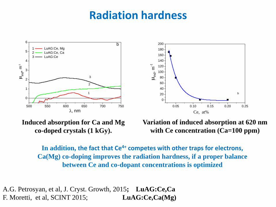
Radiation hardness
Induced absorption for Ca and Mg
co-doped crystals (1 kGy).
500 550 600 650 700 750
0
1
2
3
4
5
6
3
2
ind,
m-1
nm
1
b1 LuAG:Ce, Mg
2 LuAG:Ce, Ca
3 LuAG:Ce
A.G. Petrosyan, et al, J. Cryst. Growth, 2015; LuAG:Ce,Ca
F. Moretti, et al, SCINT 2015; LuAG:Ce,Ca(Mg)
0.05 0.10 0.15 0.20 0.25
0
20
40
60
80
100
120
140
160
180
200
Ce, at%
ind,
m-1
b
Variation of induced absorption at 620 nm
with Ce concentration (Ca=100 ppm)
In addition, the fact that Ce4+ competes with other traps for electrons, Ca(Mg) co-doping improves the radiation hardness, if a proper balance
between Ce and co-dopant concentrations is optimized
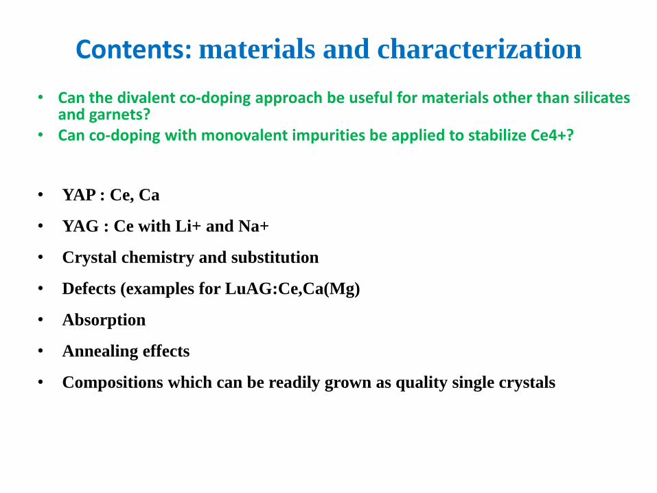
Contents: materials and characterization
• Can the divalent co-doping approach be useful for materials other than silicates and garnets?
• Can co-doping with monovalent impurities be applied to stabilize Ce4+?
• YAP : Ce, Ca
• YAG : Ce with Li+ and Na+
• Crystal chemistry and substitution
• Defects (examples for LuAG:Ce,Ca(Mg)
• Absorption
• Annealing effects
• Compositions which can be readily grown as quality single crystals
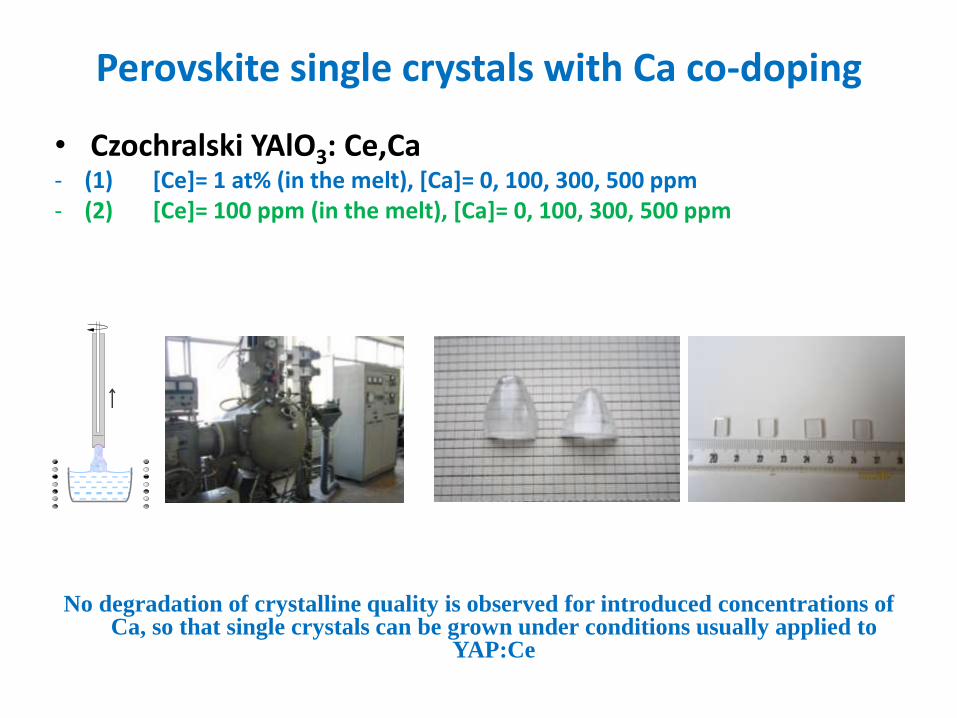
Perovskite single crystals with Ca co-doping
• Czochralski YAlO3: Ce,Ca - (1) [Ce]= 1 at% (in the melt), [Ca]= 0, 100, 300, 500 ppm - (2) [Ce]= 100 ppm (in the melt), [Ca]= 0, 100, 300, 500 ppm
No degradation of crystalline quality is observed for introduced concentrations of Ca, so that single crystals can be grown under conditions usually applied to
YAP:Ce
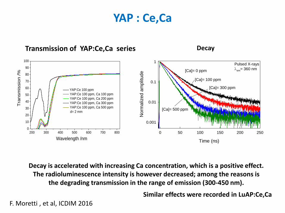
YAP : Ce,Ca
200 300 400 500 600 700 8000
10
20
30
40
50
60
70
80
90
100
Wavelength /nm
Tra
nsm
issio
n /%
YAP:Ce 100 ppm
YAP:Ce 100 ppm, Ca 100 ppm
YAP:Ce 100 ppm, Ca 200 ppm
YAP:Ce 100 ppm, Ca 300 ppm
YAP:Ce 100 ppm, Ca 500 ppm
d= 2 mm
Transmission of YAP:Ce,Ca series
Decay is accelerated with increasing Ca concentration, which is a positive effect. The radioluminescence intensity is however decreased; among the reasons is
the degrading transmission in the range of emission (300-450 nm).
Similar effects were recorded in LuAP:Ce,Ca
F. Moretti , et al, ICDIM 2016
Time (ns)
0 50 100 150 200 250
Norm
aliz
ed a
mplit
ude
0.001
0.01
0.1
1Pulsed X-rays
em= 360 nm[Ca]= 0 ppm
[Ca]= 500 ppm
[Ca]= 100 ppm
[Ca]= 300 ppm
Decay
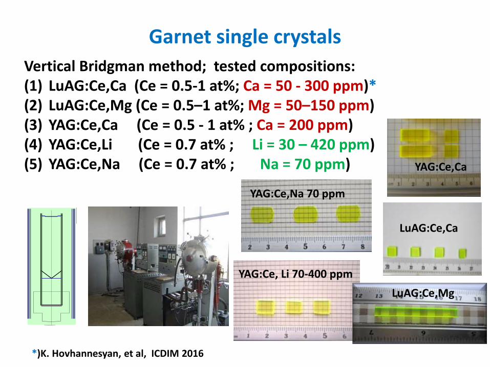
Garnet single crystals
*)K. Hovhannesyan, et al, ICDIM 2016
Vertical Bridgman method; tested compositions: (1) LuAG:Ce,Ca (Ce = 0.5-1 at%; Ca = 50 - 300 ppm)* (2) LuAG:Ce,Mg (Ce = 0.5–1 at%; Mg = 50–150 ppm) (3) YAG:Ce,Ca (Ce = 0.5 - 1 at% ; Ca = 200 ppm) (4) YAG:Ce,Li (Ce = 0.7 at% ; Li = 30 – 420 ppm) (5) YAG:Ce,Na (Ce = 0.7 at% ; Na = 70 ppm)
YAG:Ce,Na 70 ppm
YAG:Ce, Li 70-400 ppm
YAG:Ce,Ca
LuAG:Ce,Ca
LuAG:Ce,Mg
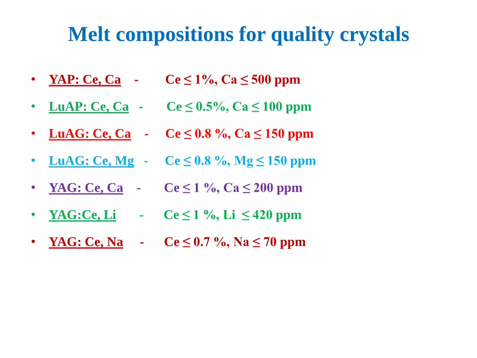
Melt compositions for quality crystals
• YAP: Ce, Ca - Ce ≤ 1%, Ca ≤ 500 ppm
• LuAP: Ce, Ca - Ce ≤ 0.5%, Ca ≤ 100 ppm
• LuAG: Ce, Ca - Ce ≤ 0.8 %, Ca ≤ 150 ppm
• LuAG: Ce, Mg - Ce ≤ 0.8 %, Mg ≤ 150 ppm
• YAG: Ce, Ca - Ce ≤ 1 %, Ca ≤ 200 ppm
• YAG:Ce, Li - Ce ≤ 1 %, Li ≤ 420 ppm
• YAG: Ce, Na - Ce ≤ 0.7 %, Na ≤ 70 ppm
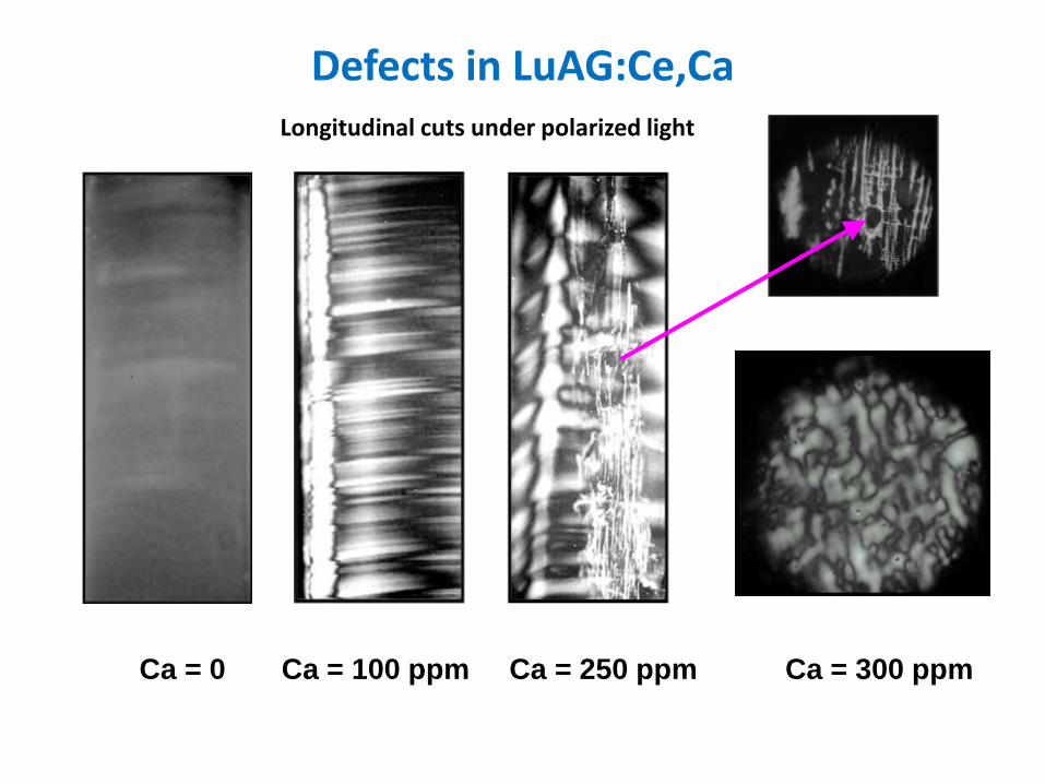
Defects in LuAG:Ce,Ca
Ca = 0 Ca = 100 ppm Ca = 250 ppm Ca = 300 ppm
Longitudinal cuts under polarized light
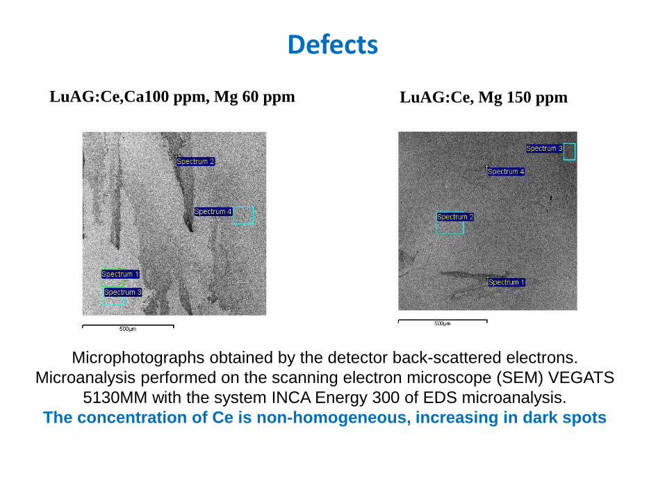
Defects
LuAG:Ce,Ca100 ppm, Mg 60 ppm
Microphotographs obtained by the detector back-scattered electrons.
Microanalysis performed on the scanning electron microscope (SEM) VEGATS
5130MM with the system INCA Energy 300 of EDS microanalysis.
The concentration of Ce is non-homogeneous, increasing in dark spots
LuAG:Ce, Mg 150 ppm
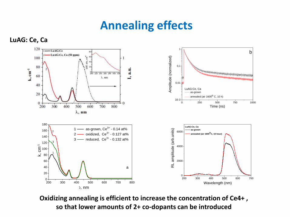
Annealing effects
Oxidizing annealing is efficient to increase the concentration of Ce4+ , so that lower amounts of 2+ co-dopants can be introduced
LuAG: Ce, Ca
0 250 500 750 10001E-3
0,01
0,1
1
Am
plit
ud
e (
norm
aliz
ed)
Time (ns)
LuAG:Ce, Ca as-grown
annealed (air 1600o C, 10 h)
b
200 300 400 500 600 7000
2000
4000
6000
LuAG:Ce, Ca
as-grown
annealed (air 1600o
C, 10 hour)
RL
am
plit
ud
e (
arb
.un
its)
Wavelength (nm)200 300 400 500 600 700 8000
20
40
60
80
100
120
140
160
180
a
1 as-grown, Ce3+ - 0.14 at%
2 oxidized, Ce3+ - 0.127 at%
3 reduced, Ce3+ - 0.132 at%
nm
k, cm
-1
1
2
3
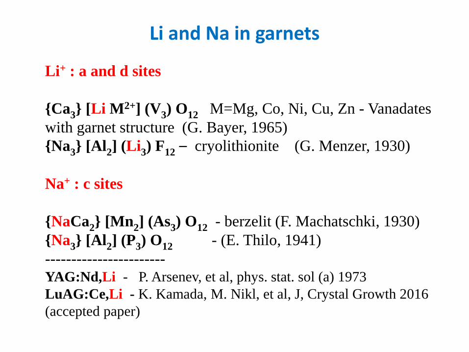
Li and Na in garnets
Li+ : a and d sites
{Ca3} [Li M2+] (V3) O12 M=Mg, Co, Ni, Cu, Zn - Vanadates
with garnet structure (G. Bayer, 1965)
{Na3} [Al2] (Li3) F12 – cryolithionite (G. Menzer, 1930)
Na+ : c sites
{NaCa2} [Mn2] (As3) O12 - berzelit (F. Machatschki, 1930)
{Na3} [Al2] (P3) O12 - (E. Thilo, 1941)
----------------------- YAG:Nd,Li - P. Arsenev, et al, phys. stat. sol (a) 1973
LuAG:Ce,Li - K. Kamada, M. Nikl, et al, J, Crystal Growth 2016
(accepted paper)
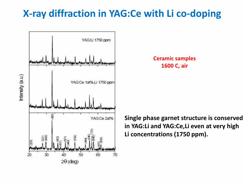
X-ray diffraction in YAG:Ce with Li co-doping
Ceramic samples 1600 C, air
Single phase garnet structure is conserved in YAG:Li and YAG:Ce,Li even at very high Li concentrations (1750 ppm).
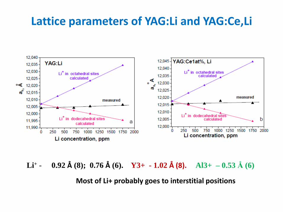
Lattice parameters of YAG:Li and YAG:Ce,Li
Li+ - 0.92 Å (8); 0.76 Å (6). Y3+ - 1.02 Å (8). Al3+ – 0.53 Å (6)
Most of Li+ probably goes to interstitial positions
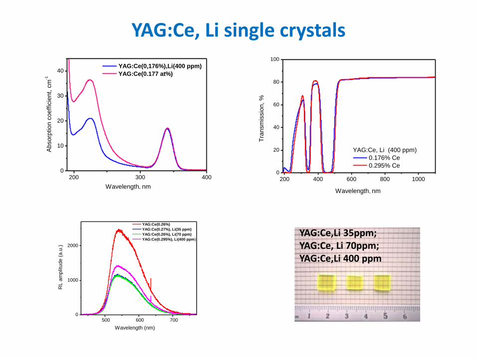
YAG:Ce, Li single crystals
500 600 700010002000RL amplitude (a.u.) Wavelength (nm) YAG:Ce(0.26%) YAG:Ce(0.27%), Li(35 ppm) YAG:Ce(0.26%), Li(70 ppm) YAG:Ce(0.295%), Li(400 ppm)200 400 600 800 1000020406080100Transmission, % YAG:Ce, Li (400 ppm) 0.176% Ce 0.295% CeWavelength nm
YAG:Ce,Li 35ppm; YAG:Ce, Li 70ppm; YAG:Ce,Li 400 ppm
200 300 4000
10
20
30
40 YAG:Ce(0,176%),Li(400 ppm)
YAG:Ce(0.177 at%)
Wavelength nm
Ab
so
rptio
n c
oe
ffic
ien
t, c
m-1
200 400 600 800 10000
20
40
60
80
100
Tra
nsm
issio
n,
%
YAG:Ce, Li (400 ppm)
0.176% Ce
0.295% Ce
Wavelength nm
500 600 7000
1000
2000
RL
am
plit
ud
e (
a.u
.)
Wavelength (nm)
YAG:Ce(0.26%)
YAG:Ce(0.27%), Li(35 ppm)
YAG:Ce(0.26%), Li(70 ppm)
YAG:Ce(0.295%), Li(400 ppm)
500 600700010002000RL amplitude (a.u.)Wavelength (nm) YAG:Ce(0.26%) YAG:Ce(0.27%), Li(35 ppm) YAG:Ce(0.26%), Li(70 ppm) YAG:Ce(0.295%), Li(400 ppm)2004006008001000020406080100Transmission, %YAG:Ce, Li (400 ppm) 0.176% Ce 0.295% CeWavelengthnm
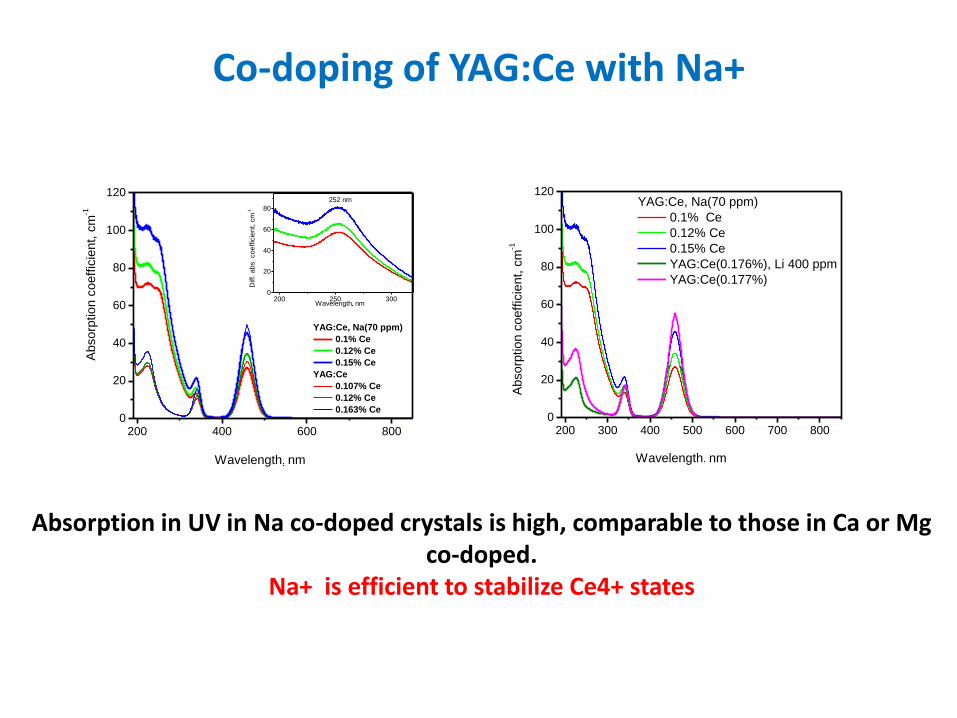
Co-doping of YAG:Ce with Na+
200 300 400 500 600 700 800020406080100120 YAG:Ce, Na(70 ppm) 0.1% Ce 0.12% Ce 0.15% Ce YAG:Ce(0.176%), Li 400 ppm YAG:Ce(0.177%)Absorption coefficient, cm-1 Wavelength nm
Absorption in UV in Na co-doped crystals is high, comparable to those in Ca or Mg co-doped.
Na+ is efficient to stabilize Ce4+ states
200 250 3000
20
40
60
80
200 400 600 8000
20
40
60
80
100
120
Wavelength nm
YAG:Ce, Na(70 ppm)
0.1% Ce
0.12% Ce
0.15% Ce
YAG:Ce
0.107% Ce
0.12% Ce
0.163% Ce
Ab
so
rptio
n c
oe
ffic
ien
t, c
m-1
Wavelength nm
Diff. a
bs. co
effic
ien
t, c
m-1
252 nm
200 300 400 500 600 700 8000
20
40
60
80
100
120YAG:Ce, Na(70 ppm)
0.1% Ce
0.12% Ce
0.15% Ce
YAG:Ce(0.176%), Li 400 ppm
YAG:Ce(0.177%)
Ab
so
rptio
n c
oe
ffic
ien
t, c
m-1
Wavelength nm
200300400500600700800020406080100120YAG:Ce, Na(70 ppm) 0.1% Ce 0.12% Ce 0.15% Ce YAG:Ce(0.176%), Li 400 ppm YAG:Ce(0.177%)Absorption coefficient, cm-1Wavelengthnm
Summary
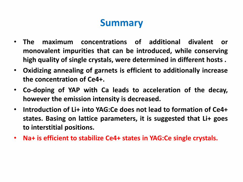
• The maximum concentrations of additional divalent or monovalent impurities that can be introduced, while conserving high quality of single crystals, were determined in different hosts .
• Oxidizing annealing of garnets is efficient to additionally increase the concentration of Ce4+.
• Co-doping of YAP with Ca leads to acceleration of the decay, however the emission intensity is decreased.
• Introduction of Li+ into YAG:Ce does not lead to formation of Ce4+ states. Basing on lattice parameters, it is suggested that Li+ goes to interstitial positions.
• Na+ is efficient to stabilize Ce4+ states in YAG:Ce single crystals.

Thank you for your attention
This work has been performed in the framework of
International Associated Laboratory IRMAS
(CNRS-France and SCS-Armenia)
and
EU H2020 programme grant n. 644260
(INTELUM)
Experimental (ILM – CNRS)
Radioluminescence spectra were recorded at RT under X-ray
irradiation. The excitation source was X-ray tube (Philips 2274)
operated at 30 kV, 20 mA, exposure time is 5 seconds.
Monochromator working in the range 430-770 nm and 230-570 nm
for YAG:Ce,Li(Ca) and LuAG:Pr,Ca respectively.
Scintillation decay measurements were performed at room
temperature under X-ray excitation using a picosecond pulsed laser
(C10196; Hamamatsu Inc.) with 100 kHz and 0.2 mA, using
interference filters YG11 and 320BP10 for YAG:Ce,Li(Ca) and
LuAG:Pr,Ca respectively. To analyze the temporal histogram for the
counts TCSPC module (PicoHarp 300) is adopted.