grundfos home booster - akvedukts booklets...product description 3 grundfos home booster 1 1....
TRANSCRIPT
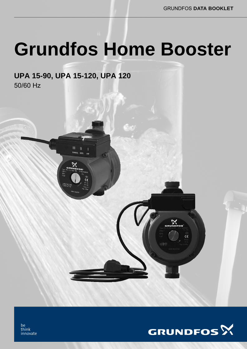
GRUNDFOS DATA BOOKLET
Grundfos Home BoosterUPA 15-90, UPA 15-120, UPA 12050/60 Hz
Ta
ble
of c
on
ten
ts
2
Grundfos Home Booster
1. Product description 3Applications . . . . . . . . . . . . . . . . . . . . . . . . . . . . . . . . . . . . . . . . . . . . . . . . . . . . . . . . . . . . . . . . . . . . . . . . . . . . . . . . . . 3Type key . . . . . . . . . . . . . . . . . . . . . . . . . . . . . . . . . . . . . . . . . . . . . . . . . . . . . . . . . . . . . . . . . . . . . . . . . . . . . . . . . . . . 3Performance range . . . . . . . . . . . . . . . . . . . . . . . . . . . . . . . . . . . . . . . . . . . . . . . . . . . . . . . . . . . . . . . . . . . . . . . . . . . . 3
2. Operating conditions 4Start-up . . . . . . . . . . . . . . . . . . . . . . . . . . . . . . . . . . . . . . . . . . . . . . . . . . . . . . . . . . . . . . . . . . . . . . . . . . . . . . . . . . . . . 4Pumped liquids . . . . . . . . . . . . . . . . . . . . . . . . . . . . . . . . . . . . . . . . . . . . . . . . . . . . . . . . . . . . . . . . . . . . . . . . . . . . . . . 4Temperature . . . . . . . . . . . . . . . . . . . . . . . . . . . . . . . . . . . . . . . . . . . . . . . . . . . . . . . . . . . . . . . . . . . . . . . . . . . . . . . . . 4Pressure. . . . . . . . . . . . . . . . . . . . . . . . . . . . . . . . . . . . . . . . . . . . . . . . . . . . . . . . . . . . . . . . . . . . . . . . . . . . . . . . . . . . . 4
3. Construction 5Sectional drawings UPA 15-90, UPA 15-120. . . . . . . . . . . . . . . . . . . . . . . . . . . . . . . . . . . . . . . . . . . . . . . . . . . . . . . . . 5Sectional drawing UPA 120 . . . . . . . . . . . . . . . . . . . . . . . . . . . . . . . . . . . . . . . . . . . . . . . . . . . . . . . . . . . . . . . . . . . . . . 6Motor UPA 15-90 (N) . . . . . . . . . . . . . . . . . . . . . . . . . . . . . . . . . . . . . . . . . . . . . . . . . . . . . . . . . . . . . . . . . . . . . . . . . . . 7Motor UPA 120 and UPA 15-120. . . . . . . . . . . . . . . . . . . . . . . . . . . . . . . . . . . . . . . . . . . . . . . . . . . . . . . . . . . . . . . . . . 7Rotor can . . . . . . . . . . . . . . . . . . . . . . . . . . . . . . . . . . . . . . . . . . . . . . . . . . . . . . . . . . . . . . . . . . . . . . . . . . . . . . . . . . . . 7Shaft with rotor. . . . . . . . . . . . . . . . . . . . . . . . . . . . . . . . . . . . . . . . . . . . . . . . . . . . . . . . . . . . . . . . . . . . . . . . . . . . . . . . 7Thrust bearing . . . . . . . . . . . . . . . . . . . . . . . . . . . . . . . . . . . . . . . . . . . . . . . . . . . . . . . . . . . . . . . . . . . . . . . . . . . . . . . . 7Bearing plate . . . . . . . . . . . . . . . . . . . . . . . . . . . . . . . . . . . . . . . . . . . . . . . . . . . . . . . . . . . . . . . . . . . . . . . . . . . . . . . . . 7Impeller . . . . . . . . . . . . . . . . . . . . . . . . . . . . . . . . . . . . . . . . . . . . . . . . . . . . . . . . . . . . . . . . . . . . . . . . . . . . . . . . . . . . . 7Pump housing . . . . . . . . . . . . . . . . . . . . . . . . . . . . . . . . . . . . . . . . . . . . . . . . . . . . . . . . . . . . . . . . . . . . . . . . . . . . . . . . 7Flow switch . . . . . . . . . . . . . . . . . . . . . . . . . . . . . . . . . . . . . . . . . . . . . . . . . . . . . . . . . . . . . . . . . . . . . . . . . . . . . . . . . . 8
4. Installation 9
5. Performance curves 10Curve conditions . . . . . . . . . . . . . . . . . . . . . . . . . . . . . . . . . . . . . . . . . . . . . . . . . . . . . . . . . . . . . . . . . . . . . . . . . . . . . 10
6. Data sheets 11
7. Product numbers 25
8. Accessories 26External flow switch for UPA 120. . . . . . . . . . . . . . . . . . . . . . . . . . . . . . . . . . . . . . . . . . . . . . . . . . . . . . . . . . . . . . . . . 26
9. Grundfos Product Center 27

Pro
du
ct
de
sc
rip
tio
n
Grundfos Home Booster 1
1. Product description
UPA 15-90, UPA 15-120 and UPA 120 circulator pumps are designed for pressure boosting of domestic water supplied from an external source in residential homes. UPA 15-90, UPA 15-120 and UPA 120 circulator pumps increase the pressure in order to make the required pressure available at showers, taps and other tapping points of domestic water.
UPA 15-90, UPA 15-120 and UPA 120 circulator pumps are used in open systems and can also be connected directly to the water main.
A flow switch starts or stops the pump when a tapping point is turned on or off. UPA 15-90 pumps have an integrated flow switch. UPA 15-120 pumps for China and Europe have an integrated flow switch. All other UPA 15-120 pumps and all UPA 120 pumps are supplied with an external flow switch, which has to be placed after the outlet of the pump.
All UPA circulator pumps are supplied with a cable and plug as required, and with fittings.
UPA 15-90, UPA 15-120 and UPA 120 circulator pumps offer a host of advantages:
• Flexibility: Suitable for installation in existing systems.
• Comfort: Low-noise operation.
• User friendliness: Plug and play.
• Reliability: Well known Grundfos quality.
ApplicationsUPA 15-90, UPA 15-120 and UPA 120 circulator pumps are designed for pressure boosting of domestic water supplied from an external source in residential homes.
UPA 15-90, UPA 15-120 and UPA 120 circulator pumps supply the required pressure for showers, taps and other tapping points for domestic water.
UPA pumps are used in open systems and can also be connected directly to the water main.
Type key
Performance range
Fig. 1 Performance range UPA 15-90, UPA 15-120, UPA 120 (230 V, 50 Hz)
Example: UP A 15 -90 N 160
Circulator pump
Automatic start/stop
Type range
Maximum head
Pump housing
Cast iron
N Stainless steel
Port-to port length [mm]
TM
06
22
80
39
14
UPA50 Hz
15-90 15-120 UPA 120
p[kPa]
H[m]
120
100
80
60
40
20
0
0.0 0.2 0.4 0.6 0.8 1.0 Q [l/s]
1.6
Q [m³/h]0.0 2.00.4 2.40.8 1.2 2.8 3.2 3.6
0
4.0 4.4
2
4
6
8
10
12
3

Op
era
ting
co
nd
ition
s
4
Grundfos Home Booster2
2. Operating conditions
Start-upThe pump must not be started until the system has been filled with liquid and vented. Furthermore, the required minimum inlet pressure must be available at the pump inlet. The system cannot be vented through the pump.
The pump is self-venting and does not require venting before start-up.
Pumped liquidsUPA 15-90, UPA 15-120 and UPA 120 circulator pumps are suitable for the these liquids:
• Fresh water
• Potable water without chemical additives
• Chlorinated potable water.
UPA 15-90, UPA 15-120 and UPA 120 circulator pumps are not suitable for the transfer of flammable liquids such as diesel oil and petrol.
Temperature
For liquid temperatures, please see also the Data sheets on page 10 and following.
Pressure
Operating pressure
For operating pressures, please see also the Data sheets on page 10 and following.
Inlet pressureTo avoid cavitation noise and risk of damage to the pump bearings, a minimum pressure of 2.0 m head/0.2 bar is required at the pump suction port during operation.
Standard pumpsMax.[°C]
Min.[°C]
Liquid temperature 60/95/110 2
Ambient temperature 40 2
Pump versionMaximum operating pressure
[MPa] [bar]
UPA 15-90 0.6 6
UPA 15-90 NetherlandsUPA 15-90 Global
1.0 10
UPA 15-120 1.0 10
UPA 120 0.6 6
UPA 120 Mexico 1.0 10
Co
ns
tru
cti
on
Grundfos Home Booster 3
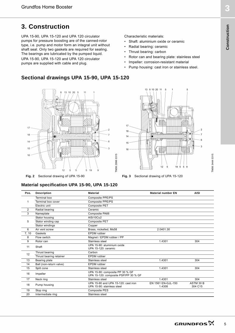
3. Construction
UPA 15-90, UPA 15-120 and UPA 120 circulator pumps for pressure boosting are of the canned-rotor type, i.e. pump and motor form an integral unit without shaft seal. Only two gaskets are required for sealing. The bearings are lubricated by the pumped liquid.
UPA 15-90, UPA 15-120 and UPA 120 circulator pumps are supplied with cable and plug.
Characteristic materials:
• Shaft: aluminium oxide or ceramic
• Radial bearing: ceramic
• Thrust bearing: carbon
• Rotor can and bearing plate: stainless steel
• Impeller: corrosion-resistant material
• Pump housing: cast iron or stainless steel.
Sectional drawings UPA 15-90, UPA 15-120
Material specification UPA 15-90, UPA 15-120
TM
06
29
96
03
15
TM
06
34
44
03
15
Fig. 2 Sectional drawing of UPA 15-90 Fig. 3 Sectional drawing of UPA 15-120
Pos. Description Material Material number EN AISI
1
Terminal box Composite PPE/PS
Terminal box cover Composite PPE/PS
Electric unit Composite PET
2 Radial bearing Ceramic
3 Nameplate Composite PA66
5
Stator housing AlSi10Cu2
Stator winding cap Composite PET
Stator windings Copper
6 Air vent screw Brass, nickelled, Ms58 2.0401.30
7, 10 Gaskets EPDM rubber
8 Flow switch Magnet / EPDM rubber / PP
9 Rotor can Stainless steel 1.4301 304
11 ShaftUPA 15-90: aluminium oxideUPA 15-120: ceramic
12Thrust bearing Carbon
Thrust bearing retainer EPDM rubber
13 Bearing plate Stainless steel 1.4301 304
14 Ball (non-return valve) EPDM rubber
15 Split cone Stainless steel 1.4301 304
16 ImpellerUPA 15-90: composite PP 30 % GFUPA 15-120: composite PSP/PP 30 % GF
17 Neck ring Stainless steel 1.4301 304
18 Pump housingUPA 15-90 and UPA 15-120: cast ironUPA 15-90: stainless steel
EN 1561 EN-GJL-1501.4308
ASTM 30 B304 C15
19 Stop ring Composite PES
20 Intermediate ring Stainless steel
13 10 20 11 1
2
7
6
3
17
18
14
15
16
12 195 9
8 5
5 5
17
18
14
15
16
12 19 5 9
2
7
6
3
13 10 20 11 18 5
5 5
5
5
Co
ns
truc
tion
6
Grundfos Home Booster3
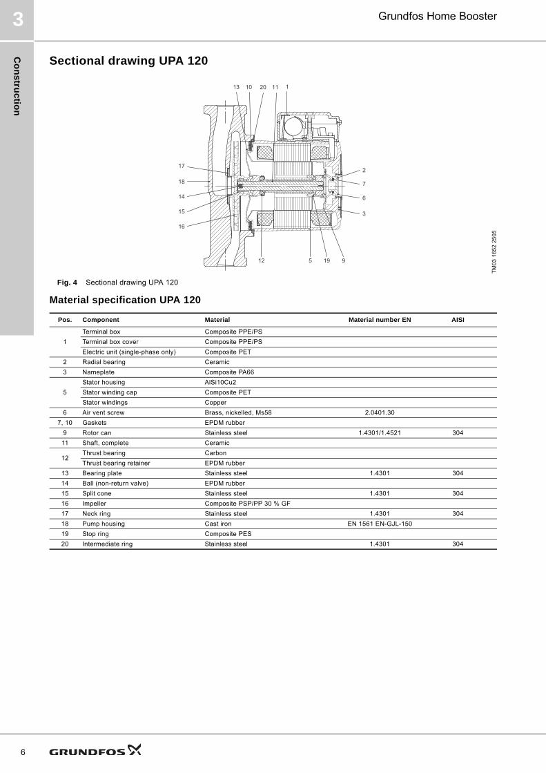
Sectional drawing UPA 120
Fig. 4 Sectional drawing UPA 120
Material specification UPA 120
TM
03
16
52
25
05
7
2
13
17
10 11 1
6
3
18
14
15
16
512 19 9
20
Pos. Component Material Material number EN AISI
1
Terminal box Composite PPE/PS
Terminal box cover Composite PPE/PS
Electric unit (single-phase only) Composite PET
2 Radial bearing Ceramic
3 Nameplate Composite PA66
5
Stator housing AlSi10Cu2
Stator winding cap Composite PET
Stator windings Copper
6 Air vent screw Brass, nickelled, Ms58 2.0401.30
7, 10 Gaskets EPDM rubber
9 Rotor can Stainless steel 1.4301/1.4521 304
11 Shaft, complete Ceramic
12Thrust bearing Carbon
Thrust bearing retainer EPDM rubber
13 Bearing plate Stainless steel 1.4301 304
14 Ball (non-return valve) EPDM rubber
15 Split cone Stainless steel 1.4301 304
16 Impeller Composite PSP/PP 30 % GF
17 Neck ring Stainless steel 1.4301 304
18 Pump housing Cast iron EN 1561 EN-GJL-150
19 Stop ring Composite PES
20 Intermediate ring Stainless steel 1.4301 304
Co
ns
tru
cti
on
Grundfos Home Booster 3
Motor UPA 15-90 (N)The motor is a 2-pole, asynchronous, squirrel-cage motor. The motor has a built-in impedance protection and is short-circuit-proof. No external motor protection is required. The terminal box is easily accessible and has functional cable-connecting terminals. The cable entry is tight and incorporates cable relief.
Motor UPA 120 and UPA 15-120The motor is a 2-pole, asynchronous, squirrel-cage motor. The motor incorporates thermal overload protection. Therefore, no external motor protection is required. The terminal box is easily accessible and has functional cable-connecting terminals. The cable entry is tight and incorporates cable relief including the plug.
Rotor canThe rotor can is closed with an air vent screw fitted directly at the top.
The upper radial bearing is incorporated in the top of the rotor can, and ground and honed with great precision.
Shaft with rotorThe rotor is secured to the shaft with a pipe and an elastic sleeve. The rotor is totally encapsulated in a stainless-steel cladding. To avoid precipitation of calcium in the radial bearings, the shaft has been plunge-ground at the bearing entries.
The shaft has a through-going hole to ensure perfect lubrication and cooling of the upper bearing. See sectional drawings.
To prevent system water under pressure from running out when the air vent screw is removed, a non-return valve (rubber ball) is incorporated at the impeller end of the shaft.
The air in the rotor chamber escapes out into the system through the hole in the shaft.
Thrust bearingThe thrust bearing is secured to the shaft by a spherically flexible suspension.
Bearing plateThe lower radial bearing is pressed into the bearing plate, and ground and honed with great precision.
Due to the relatively large surface of the bearing plate, the motor heat is carried away from the rotor can by the pumped liquid.
ImpellerThe impeller is a radial impeller with curved composite blades. It is secured to the shaft by a split cone.
Pump housing
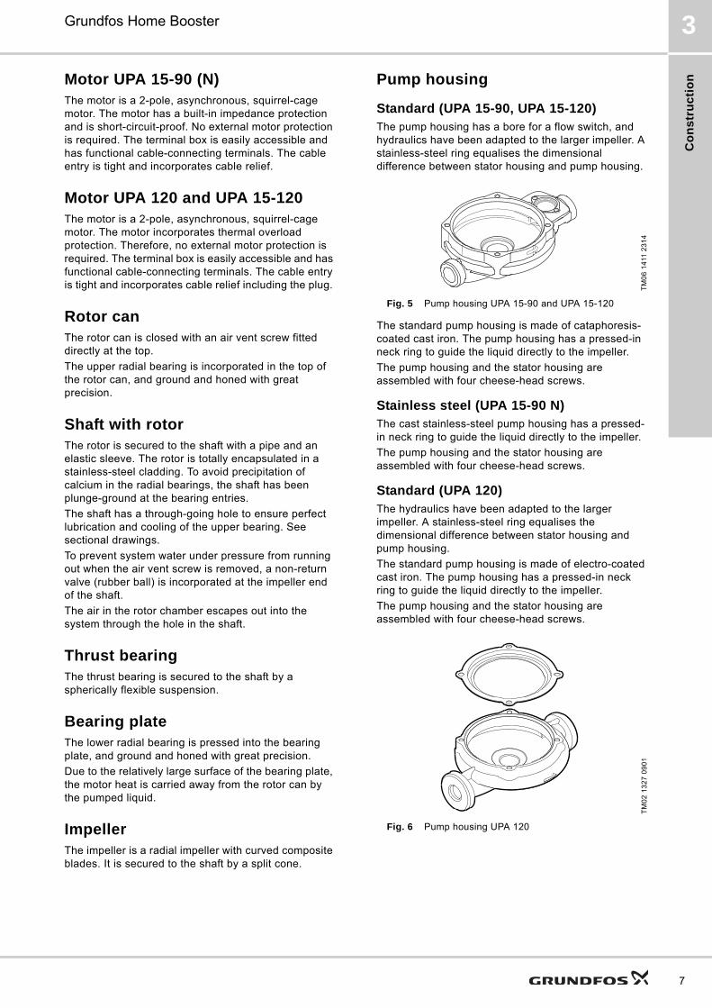
Standard (UPA 15-90, UPA 15-120)The pump housing has a bore for a flow switch, and hydraulics have been adapted to the larger impeller. A stainless-steel ring equalises the dimensional difference between stator housing and pump housing.
Fig. 5 Pump housing UPA 15-90 and UPA 15-120
The standard pump housing is made of cataphoresis- coated cast iron. The pump housing has a pressed-in neck ring to guide the liquid directly to the impeller.
The pump housing and the stator housing are assembled with four cheese-head screws.
Stainless steel (UPA 15-90 N)The cast stainless-steel pump housing has a pressed-in neck ring to guide the liquid directly to the impeller.
The pump housing and the stator housing are assembled with four cheese-head screws.
Standard (UPA 120)The hydraulics have been adapted to the larger impeller. A stainless-steel ring equalises the dimensional difference between stator housing and pump housing.
The standard pump housing is made of electro-coated cast iron. The pump housing has a pressed-in neck ring to guide the liquid directly to the impeller.
The pump housing and the stator housing are assembled with four cheese-head screws.
Fig. 6 Pump housing UPA 120
TM
06
14
11 2
31
4T
M0
2 1
32
7 0
90
1
7

Co
ns
truc
tion
8
Grundfos Home Booster3
Flow switch
UPA 15-90The flow switch consists of an arm with a magnet (1), that moves in a chamber (2). The chamber is separated from the pumped liquid and the terminal box. The magnetic field activates a magnetic contact (3).
Fig. 7 UPA 15-90 flow switch in "OFF" position
The pump selector can be set to the positions "OFF", "AUTO" and "MANUAL".
* When the selector is in position "MANUAL", at least one tap must be open. Otherwise the pumped liquid may become too hot.
UPA 15-120The flow switch consists of an arm with a magnet (1), that moves in a chamber (2). The chamber is separated from the pumped liquid and the terminal box. The magnetic field activates a magnetic contact (3).
Fig. 8 UPA 15-120 flow switch
The UPA 15-120 doesn’t contain an On/Off switch.
TM
01
72
51
41
99
Selector in positions Description
I OFF The pump is switched off.
II AUTOThe pump starts and stops automatically (when the flow exceeds or falls below 90-120 l/h).
III MANUAL*The pump runs continuously (even if tapping points are turned off).
3
1
2
TM
06
51
04
33
15
3
1
2

Ins
tall
ati
on
Grundfos Home Booster 4
4. Installation
The pump must always be installed with horizontal motor shaft. At start-up, the rotor can must be vented by removing the plug from the top of the motor.
Within a short time, the rotor forces the remaining air out into the system via the shaft.
UPA 120 and UPA 15-120 pumps can be installed vertically or horizontally. The mounting position is limited by the length of the cable between the external flow switch and the terminal box.
The terminal box of the UPA 15-90 has to be on the outlet of the pump, because of the built-in flow switch.
Note: As the pumps have drain holes, the terminal box must not face downwards.
Fig. 9 Installation directions
TM
06
22
51
38
14
9
Pe
rform
an
ce
cu
rve
s
10
5
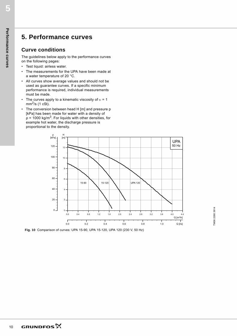
5. Performance curves
Curve conditionsThe guidelines below apply to the performance curves on the following pages:
• Test liquid: airless water.
• The measurements for the UPA have been made at a water temperature of 20 °C.
• All curves show average values and should not be used as guarantee curves. If a specific minimum performance is required, individual measurements must be made.
• The curves apply to a kinematic viscosity of = 1 mm2/s (1 cSt).
• The conversion between head H [m] and pressure p [kPa] has been made for water with a density of ρ = 1000 kg/m3. For liquids with other densities, for example hot water, the discharge pressure is proportional to the density.
Fig. 10 Comparison of curves: UPA 15-90, UPA 15-120, UPA 120 (230 V, 50 Hz)
TM
06
22
80
39
14
UPA50 Hz
15-90 15-120 UPA 120
p[kPa]
H[m]
120
100
80
60
40
20
0
0.0 0.2 0.4 0.6 0.8 1.0 Q [l/s]
1.6
Q [m³/h]0.0 2.00.4 2.40.8 1.2 2.8 3.2 3.6
0
4.0 4.4
2
4
6
8
10
12
Da
ta s
he
ets
6
6. Data sheets
UPA 15-90, 1 x 230 V, 50 Hz
China, Argentina, Czech Republic, Turkey, Romania, Indonesia
Dimensions
TM
01
68
93
36
99
0.0 0.2 0.4 0.6 0.8 1.0 1.2 1.4 1.6 Q [m³/h]0.0
1.0
2.0
3.0
4.0
5.0
6.0
7.0
8.0
H[m]
0
15
30
45
60
75
p[kPa]
0.00 0.05 0.10 0.15 0.20 0.25 0.30 0.35 0.40 0.45 Q [l/s]
P1max [W] I1/1 [A]
120 0.48
TM
05
25
34
02
12
G
B1 B2 H2H1
L2L1
Enclosure class: IPX2D
Connections: Rp 3/4 - Rp 1/2 unions
Operating pressure: Max. 6 bar
Liquid temperature: +2 °C to +95 °C (TF 95)
Pump typeDimensions [mm] Weights [kg] Shipping volume
[m3]L1 L2 H1 H2 B1 B2 G Net Gross
UPA 15-90 160 214 23 103 50 54 3/4" 2.5 2.7 0.0042
11
Da
ta s
he
ets
12
6
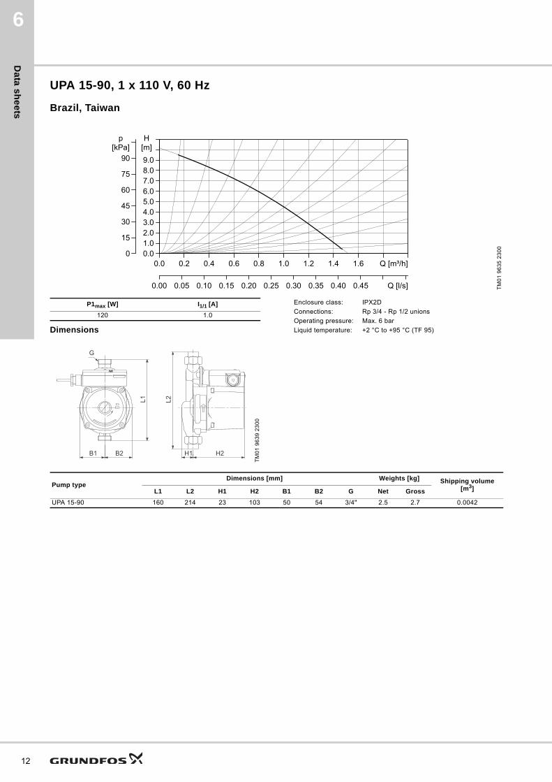
UPA 15-90, 1 x 110 V, 60 Hz
Brazil, Taiwan
Dimensions
TM
01
96
35
23
00
0.0 0.2 0.4 0.6 0.8 1.0 1.2 1.4 1.6 Q [m³/h]0.01.02.03.04.05.06.07.08.09.0
H[m]
0
15
30
45
60
75
90
p[kPa]
0.00 0.05 0.10 0.15 0.20 0.25 0.30 0.35 0.40 0.45 Q [l/s]
P1max [W] I1/1 [A]
120 1.0
TM
01
96
39
23
00
G
B1 B2 H2H1
L2L1
Enclosure class: IPX2D
Connections: Rp 3/4 - Rp 1/2 unions
Operating pressure: Max. 6 bar
Liquid temperature: +2 °C to +95 °C (TF 95)
Pump typeDimensions [mm] Weights [kg] Shipping volume
[m3]L1 L2 H1 H2 B1 B2 G Net Gross
UPA 15-90 160 214 23 103 50 54 3/4" 2.5 2.7 0.0042
Da
ta s
he
ets
6
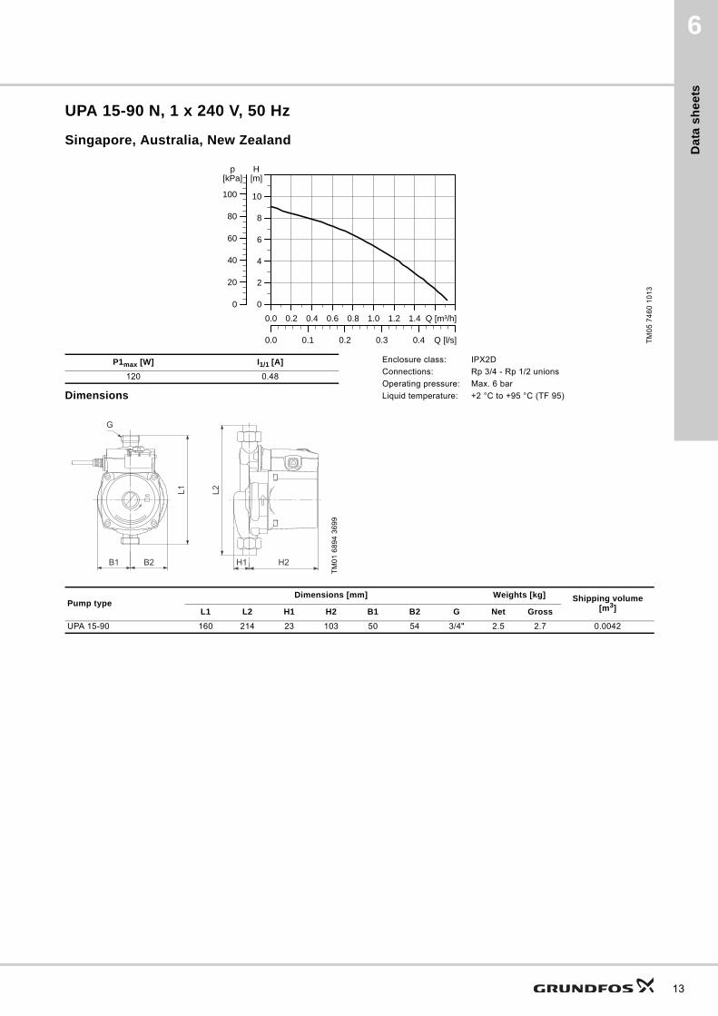
UPA 15-90 N, 1 x 240 V, 50 Hz
Singapore, Australia, New Zealand
Dimensions
TM
05
74
60
10
13
0.0 0.2 0.4 0.6 0.8 1.0 1.2 1.4 Q [m³/h]0
2
4
6
8
10
H[m]
0
20
40
60
80
100
[kPa]p
0.0 0.1 0.2 0.3 0.4 Q [l/s]
P1max [W] I1/1 [A]
120 0.48
TM
01
68
94
36
99
G
B1 B2 H2H1
L2L1
Enclosure class: IPX2D
Connections: Rp 3/4 - Rp 1/2 unions
Operating pressure: Max. 6 bar
Liquid temperature: +2 °C to +95 °C (TF 95)
Pump typeDimensions [mm] Weights [kg] Shipping volume
[m3]L1 L2 H1 H2 B1 B2 G Net Gross
UPA 15-90 160 214 23 103 50 54 3/4" 2.5 2.7 0.0042
13

Da
ta s
he
ets
14
6
UPA 15-90, 1 x 220 V, 60 Hz
Brazil, Korea, Taiwan
Dimensions
TM
01
96
36
23
00
0.0 0.2 0.4 0.6 0.8 1.0 1.2 1.4 1.6 Q [m³/h]0.01.02.03.04.05.06.07.08.09.0
H[m]
0
15
30
45
60
75
90
p[kPa]
0.00 0.05 0.10 0.15 0.20 0.25 0.30 0.35 0.40 0.45 0.50Q [l/s]
P1max [W] I1/1 [A]
120 0.48
TM
01
68
94
36
99
G
B1 B2 H2H1
L2L1
Enclosure class: IPX2D
Connections: Rp 3/4 - Rp 1/2 unions
Operating pressure: Max. 6 bar
Liquid temperature: +2 °C to +95 °C (TF 95)
Pump typeDimensions [mm] Weights [kg] Shipping volume
[m3]L1 L2 H1 H2 B1 B2 G Net Gross
UPA 15-90 160 214 23 103 50 54 3/4" 2.5 2.7 0.0042
Da
ta s
he
ets
6
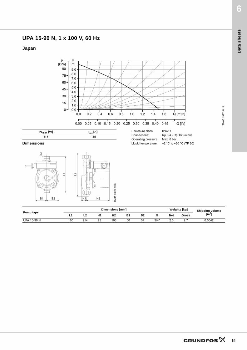
UPA 15-90 N, 1 x 100 V, 60 Hz
Japan
Dimensions
TM
06
19
27
34
14
0.0 0.2 0.4 0.6 0.8 1.0 1.2 1.4 1.6 Q [m³/h]0.01.02.03.04.05.06.07.08.09.0
H[m]
0
15
30
45
60
75
90
p[kPa]
0.00 0.05 0.10 0.15 0.20 0.25 0.30 0.35 0.40 0.45 Q [l/s]
P1max [W] I1/1 [A]
115 1.15
TM
01
96
39
23
00
G
B1 B2 H2H1
L2L1
Enclosure class: IPX2D
Connections: Rp 3/4 - Rp 1/2 unions
Operating pressure: Max. 6 bar
Liquid temperature: +2 °C to +60 °C (TF 60)
Pump typeDimensions [mm] Weights [kg] Shipping volume
[m3]L1 L2 H1 H2 B1 B2 G Net Gross
UPA 15-90 N 160 214 23 103 50 54 3/4" 2.5 2.7 0.0042
15

Da
ta s
he
ets
16
6
UPA 15-90, 1 x 230 V, 50 Hz
UK, India, Russia, Global
Dimensions
TM
01
68
93
36
99
0.0 0.2 0.4 0.6 0.8 1.0 1.2 1.4 1.6 Q [m³/h]0.0
1.0
2.0
3.0
4.0
5.0
6.0
7.0
8.0
H[m]
0
15
30
45
60
75
p[kPa]
0.00 0.05 0.10 0.15 0.20 0.25 0.30 0.35 0.40 0.45 Q [l/s]
P1max [W] I1/1 [A]
120 0.48
TM
01
96
39
23
00
G
B1 B2 H2H1
L2L1
Enclosure class: IPX2D
Connections: Rp 3/4 - Rp 1/2 unions
Operating pressure: Max. 6 bar / Max. 10 bar (Global only)
Liquid temperature: +2 °C to +95 °C (TF 95)
Pump typeDimensions [mm] Weights [kg] Shipping volume
[m3]L1 L2 H1 H2 B1 B2 G Net Gross
UPA 15-90 160 214 23 103 50 54 3/4" 2.5 2.7 0.0042

Da
ta s
he
ets
6
UPA 15-90 N, 1 x 230 V, 50 Hz
Netherlands, UK
Dimensions
TM
01
68
93
36
99
0.0 0.2 0.4 0.6 0.8 1.0 1.2 1.4 1.6 Q [m³/h]0.0
1.0
2.0
3.0
4.0
5.0
6.0
7.0
8.0
H[m]
0
15
30
45
60
75
p[kPa]
0.00 0.05 0.10 0.15 0.20 0.25 0.30 0.35 0.40 0.45 Q [l/s]
P1max [W] I1/1 [A]
120 0.48
TM
01
96
39
23
00
G
B1 B2 H2H1
L2L1
Enclosure class: IPX2D
Connections: Rp 3/4 - Rp 1/2 unions
Operating pressure: Max. 6 bar / Max. 10 bar (Netherlands only)
Liquid temperature: +2 °C to +95 °C (TF 95)
Pump typeDimensions [mm] Weights [kg] Shipping volume
[m3]L1 L2 H1 H2 B1 B2 G Net Gross
UPA 15-90 160 214 23 103 50 54 3/4" 2.5 2.7 0.0042
17

Da
ta s
he
ets
18
6
UPA 15-90, 1 x 127 V, 60 Hz
Mexico
TM
05
74
60
10
13
0.0 0.2 0.4 0.6 0.8 1.0 1.2 1.4 Q [m³/h]0
2
4
6
8
10
H[m]
0
20
40
60
80
100
[kPa]p
0.0 0.1 0.2 0.3 0.4 Q [l/s]
P1max [W] I1/1 [A]
120 1
TM
01
96
39
23
00
G
B1 B2 H2H1
L2L1
Enclosure class: IPX2D
Connections: Rp 3/4 - Rp 1/2 unions
Operating pressure: Max. 6 bar
Liquid temperature: +2 °C to +60 °C (TF 60)
Pump type
Dimensions [mm] Weights [kg]Shipping volume
[m3]L1 L2 H1 H2 B1 B2 GNet[kg]
Gross[kg]
UPA 15-90 160 214 23 103 50 54 3/4" 2.5 2.7 0.0042

Da
ta s
he
ets
6
UPA 15-120, 1 x 230 V, 50 Hz
Europe
TM
06
20
52
38
14
��� ��� ��� ��� ��� ��� ��� ��� ��� ��� �� ����
�
�
�
�
��
��
����
�
��
��
��
��
���
���������
��� ��� ��� ��� ��� ��� �����
P1max [W] I1/1 [A]
200 0.89
TM
06
51
03
33
15
H1 H2
L1
B2B1
G
Enclosure class: IPX2D
Connections: Rp 1 - Rp 1/2 unions
Operating pressure: Max. 10 bar
Liquid temperature: +2 °C to +95 °C (TF 95)
Pump type
Dimensions [mm] Weights [kg]Shipping volume
[m3]L1 H1 H2 B1 B2 GNet[kg]
Gross[kg]
UPA 120 200 20 130 63 69 1" 4.7 5.1 0.0058
19

Da
ta s
he
ets
20
6
UPA 15-120, 1 x 230 V, 50 Hz
China
TM
06
20
52
38
14
��� ��� ��� ��� ��� ��� ��� ��� ��� ��� �� ����
�
�
�
�
��
��
����
�
��
��
��
��
���
���������
��� ��� ��� ��� ��� ��� �����
P1max [W] I1/1 [A]
200 0.89
TM
06
51
03
33
15
H1 H2
L1
B2B1
G
Enclosure class: IPX2D
Connections: Rp 1- Rp 1/2 unions
Operating pressure: Max. 10 bar
Liquid temperature: +2 °C to +95 °C (TF 95)
Pump typeDimensions [mm] Weights [kg] Shipping volume
[m3]L1 H1 H2 B1 B2 G Net Gross
UPA 15-120 200 20 130 63 69 1" 4.7 5 0.0058
Da
ta s
he
ets
6
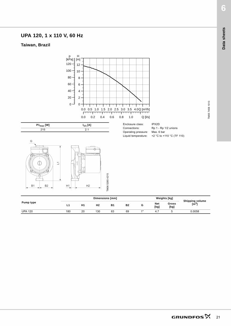
UPA 120, 1 x 110 V, 60 Hz
Taiwan, Brazil
TM
05
74
58
10
13
0.0 0.5 1.0 1.5 2.0 2.5 3.0 3.5 4.0Q [m³/h]0
2
4
6
8
10
12
H[m]
0
20
40
60
80
100
120[kPa]
p
0.0 0.2 0.4 0.6 0.8 1.0 Q [l/s]
P1max [W] I1/1 [A]
215 2.1
TM
06
52
65
42
15
H1 H2
L1
B2B1
G
Enclosure class: IPX2D
Connections: Rp 1 - Rp 1/2 unions
Operating pressure: Max. 6 bar
Liquid temperature: +2 °C to +110 °C (TF 110)
Pump type
Dimensions [mm] Weights [kg]Shipping volume
[m3]L1 H1 H2 B1 B2 GNet[kg]
Gross[kg]
UPA 120 180 20 130 63 69 1" 4.7 5 0.0058
21

Da
ta s
he
ets
22
6
UPA 120, 1 x 220 V, 60 Hz
Taiwan, Brazil, Korea
TM
05
74
62
10
13
0.0 0.5 1.0 1.5 2.0 2.5 3.0 3.5 4.0Q [m³/h]0
2
4
6
8
10
12
H[m]
0
20
40
60
80
100
120[kPa]
p
0.0 0.2 0.4 0.6 0.8 1.0 Q [l/s]
P1max [W] I1/1 [A]
220 1.05
TM
06
52
65
42
15
H1 H2
L1
B2B1
G
Enclosure class: IPX2D
Connections: Rp 1 - Rp 1/2 unions
Operating pressure: Max. 6 bar
Liquid temperature: +2 °C to +110 °C (TF 110)
Pump type
Dimensions [mm] Weights [kg]Shipping volume
[m3]L1 H1 H2 B1 B2 GNet[kg]
Gross[kg]
UPA 120 180 20 130 63 69 1" 4.7 5 0.0058
Da
ta s
he
ets
6
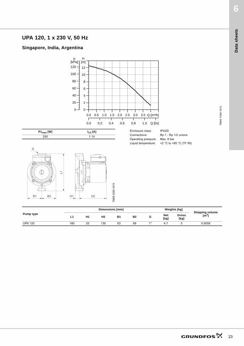
UPA 120, 1 x 230 V, 50 Hz
Singapore, India, Argentina
TM
05
74
59
10
13
0.0 0.5 1.0 1.5 2.0 2.5 3.0 3.5 Q [m³/h]0
2
4
6
8
10
12
H[m]
0
20
40
60
80
100
120[kPa]
p
0.0 0.2 0.4 0.6 0.8 1.0 Q [l/s]
P1max [W] I1/1 [A]
250 1.14
TM
06
52
65
42
15
H1 H2
L1
B2B1
G
Enclosure class: IPX2D
Connections: Rp 1 - Rp 1/2 unions
Operating pressure: Max. 6 bar
Liquid temperature: +2 °C to +95 °C (TF 95)
Pump type
Dimensions [mm] Weights [kg]Shipping volume
[m3]L1 H1 H2 B1 B2 GNet[kg]
Gross[kg]
UPA 120 180 20 130 63 69 1" 4.7 5 0.0058
23
Da
ta s
he
ets
24
6
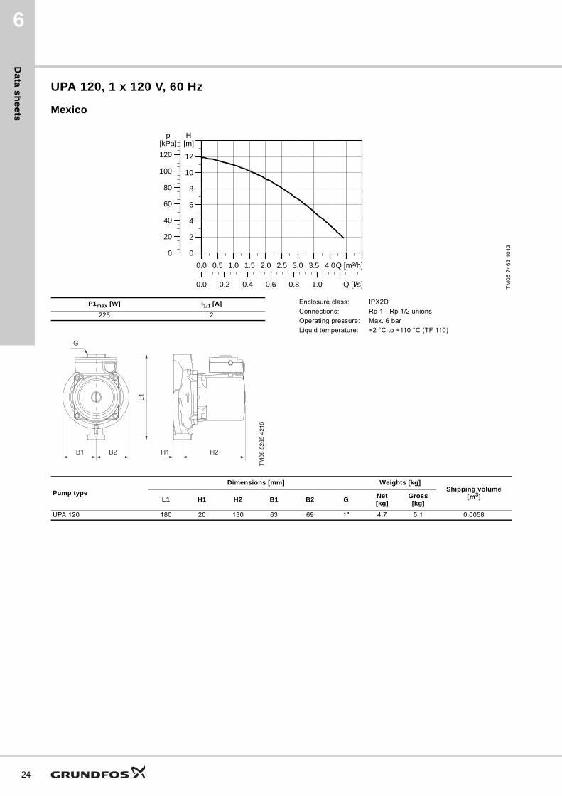
UPA 120, 1 x 120 V, 60 Hz
Mexico
TM
05
74
63
10
13
0.0 0.5 1.0 1.5 2.0 2.5 3.0 3.5 4.0Q [m³/h]0
2
4
6
8
10
12
H[m]
0
20
40
60
80
100
120[kPa]
p
0.0 0.2 0.4 0.6 0.8 1.0 Q [l/s]
P1max [W] I1/1 [A]
225 2
TM
06
52
65
42
15
H1 H2
L1
B2B1
G
Enclosure class: IPX2D
Connections: Rp 1 - Rp 1/2 unions
Operating pressure: Max. 6 bar
Liquid temperature: +2 °C to +110 °C (TF 110)
Pump type
Dimensions [mm] Weights [kg]Shipping volume
[m3]L1 H1 H2 B1 B2 GNet[kg]
Gross[kg]
UPA 120 180 20 130 63 69 1" 4.7 5.1 0.0058

Pro
du
ct
nu
mb
ers
Grundfos Home Booster 7
7. Product numbers
Market Pump typePort-to-port
length[mm]
Terminal box position
ConnectionVoltage
[V]Frequency
[Hz]Product number
Data sheet page
ArgentinaUPA 15-90 160 12 H G 3/4 230 50 59539502 11
UPA 120 180 12 H G 1 230 50 52588423 23
Australia and New Zealand
UPA 15-90 N 160 12 H G 3/4 240 50 59539508 13
Brazil
UPA 15-90 160 12 H G 3/4 110 60 59539518 12
UPA 15-90 160 12 H G 3/4 220 60 59539517 14
UPA 120 180 12 H G 1 110 60 52588421 21
UPA 120 180 12 H G 1 220 60 52588420 22
Brazil (white colour)
UPA 15-90 160 12 H G 3/4 110 60 98559024 12
UPA 15-90 160 12 H G 3/4 220 60 98559114 14
UPA 120 180 12 H G 1 110 60 98559136 21
UPA 120 180 12 H G 1 220 60 98559140 22
ChinaUPA 15-90 160 12 H G 3/4 230 50 59539500 11
UPA 15-120 200 12 H G 1 230 50 98699697 20
Czech Republic UPA 15-90 160 12 H G 3/4 230 50 59539514 11
Europe UPA 15-120 200 12 H G 1 230 50 98699677 19
Global UPA 15-90 160 12 H G 3/4 230 50 59539521 16
Netherlands UPA 15-90 N 160 12 H G 3/4 230 50 96621403 17
IndiaUPA 15-90 160 12 H G 3/4 230 50 59539511 16
UPA 120 180 12 H G 1 230 50 52588416 23
Indonesia UPA 15-90 160 12 H G 3/4 230 50 59539519 11
Japan UPA 15-90 N 160 12 H G 3/4 100 60 59539505 15
KoreaUPA 15-90 160 12 H G 3/4 220 60 59539513 14
UPA 120 180 12 H G 1 220 60 52588418 22
MexicoUPA 15-90 160 12 H G 3/4 127 60 59539520 18
UPA 120 180 12 H G 1 120 60 52588422 24
Romania UPA 15-90 160 12 H G 3/4 230 50 59539516 11
Russia UPA 15-90 160 12 H G 3/4 230 50 59539512 16
SingaporeUPA 15-90 N 160 12 H G 3/4 240 50 59539509 13
UPA 120 180 12 H G 1 230 50 52588415 23
Taiwan
UPA 15-90 160 12 H G 3/4 110 60 59539506 12
UPA 15-90 160 12 H G 3/4 220 60 59539507 14
UPA 120 180 12 H G 1 110 60 52588413 21
UPA 120 180 12 H G 1 220 60 52588414 22
Turkey UPA 15-90 160 12 H G 3/4 230 50 59539515 11
UKUPA 15-90 N 160 12 H G 3/4 230 50 97620721 17
UPA 15-90 160 12 H G 3/4 230 50 59539510 16
25

Ac
ce
ss
orie
s
26
Grundfos Home Booster8
8. Accessories
External flow switch for UPA 120
Fig. 11 External flow switch for UPA 120
TM
06
51
93
411
5T
M0
6 5
16
2 3
91
5
DescriptionProduct number
External flow switch for UPA 120 91760166

Gru
nd
fos
Pro
du
ct
Ce
nte
r
27
Grundfos Home Booster 9
9. Grundfos Product Center
Subject to alterations.
All the information you need in one place Downloads
Performance curves, technical specifications, pictures, dimensional drawings, motor curves, wiring diagrams, spare parts, service kits, 3D drawings, documents, system parts. The Product Center displays any recent and saved items - including complete projects - right on the main page.
On the product pages, you can download installation and operating instructions, data booklets, service instructions, etc. in PDF format.
SIZING enables you to size a pump based on entered data and selection choices.
Online search and sizing tool to help you make the right choice.
http://product-selection.grundfos.com
REPLACEMENT enables you to find a replacement product.Search results will include information on
• the lowest purchase price• the lowest energy consumption• the lowest total life cycle cost.
CATALOGUE gives you access to the Grundfos product catalogue.
LIQUIDS enables you to find pumps designed for aggressive, flammable or other special liquids.

GRUNDFOS A/S DK-8850 Bjerringbro . DenmarkTelephone: +45 87 50 14 00www.grundfos.com
98715166 1015
ECM: 1168460 Th
e n
am
e G
run
dfo
s, t
he
Gru
nd
fos
log
o,
an
d b
e t
hin
k i
nn
ov
ate
are
re
gis
tere
d t
rad
em
ark
s o
wn
ed
by
Gru
nd
fos
Ho
ldin
g A
/S o
r G
run
dfo
s A
/S,
De
nm
ark
. A
ll ri
gh
ts r
ese
rve
d w
orl
dw
ide
.©
Co
pyr
igh
t G
run
dfo
s H
old
ing
A/S