grundfos rsi - solar solved · system components 6 3 grundfos rsi 3. system components an rsi...
TRANSCRIPT
GRUNDFOS DATA BOOKLET
Grundfos RSIRenewable solar inverter for pump control1.5 - 37 kW
Ta
ble
of c
on
ten
ts
2
Grundfos RSI
1. Product introduction 3General description . . . . . . . . . . . . . . . . . . . . . . . . . . . . . . . . . . . . . . . . . . . . . . . . . . . . . . . . . . . . . . . . . . . . . . . . . . . . 3Features and benefits . . . . . . . . . . . . . . . . . . . . . . . . . . . . . . . . . . . . . . . . . . . . . . . . . . . . . . . . . . . . . . . . . . . . . . . . . . 3Type key . . . . . . . . . . . . . . . . . . . . . . . . . . . . . . . . . . . . . . . . . . . . . . . . . . . . . . . . . . . . . . . . . . . . . . . . . . . . . . . . . . . . 4
2. Applications 5
3. System components 6Pumps . . . . . . . . . . . . . . . . . . . . . . . . . . . . . . . . . . . . . . . . . . . . . . . . . . . . . . . . . . . . . . . . . . . . . . . . . . . . . . . . . . . . . . 6Renewable Solar Inverter . . . . . . . . . . . . . . . . . . . . . . . . . . . . . . . . . . . . . . . . . . . . . . . . . . . . . . . . . . . . . . . . . . . . . . . 6Circuit breaker, AC (optional). . . . . . . . . . . . . . . . . . . . . . . . . . . . . . . . . . . . . . . . . . . . . . . . . . . . . . . . . . . . . . . . . . . . . 6Sine wave filter (optional). . . . . . . . . . . . . . . . . . . . . . . . . . . . . . . . . . . . . . . . . . . . . . . . . . . . . . . . . . . . . . . . . . . . . . . . 6Solar panel. . . . . . . . . . . . . . . . . . . . . . . . . . . . . . . . . . . . . . . . . . . . . . . . . . . . . . . . . . . . . . . . . . . . . . . . . . . . . . . . . . . 6Dry-running switch . . . . . . . . . . . . . . . . . . . . . . . . . . . . . . . . . . . . . . . . . . . . . . . . . . . . . . . . . . . . . . . . . . . . . . . . . . . . . 6Circuit breaker, DC . . . . . . . . . . . . . . . . . . . . . . . . . . . . . . . . . . . . . . . . . . . . . . . . . . . . . . . . . . . . . . . . . . . . . . . . . . . . 7Combiner box (optional). . . . . . . . . . . . . . . . . . . . . . . . . . . . . . . . . . . . . . . . . . . . . . . . . . . . . . . . . . . . . . . . . . . . . . . . . 7Surge protection, DC . . . . . . . . . . . . . . . . . . . . . . . . . . . . . . . . . . . . . . . . . . . . . . . . . . . . . . . . . . . . . . . . . . . . . . . . . . . 7Level switch (optional) . . . . . . . . . . . . . . . . . . . . . . . . . . . . . . . . . . . . . . . . . . . . . . . . . . . . . . . . . . . . . . . . . . . . . . . . . . 7
4. Technical data 8Dimensions . . . . . . . . . . . . . . . . . . . . . . . . . . . . . . . . . . . . . . . . . . . . . . . . . . . . . . . . . . . . . . . . . . . . . . . . . . . . . . . . . . 8Electrical and enclosure data. . . . . . . . . . . . . . . . . . . . . . . . . . . . . . . . . . . . . . . . . . . . . . . . . . . . . . . . . . . . . . . . . . . . 11Technical data for circuit breaker, DC . . . . . . . . . . . . . . . . . . . . . . . . . . . . . . . . . . . . . . . . . . . . . . . . . . . . . . . . . . . . . 11Technical data for surge protection, DC . . . . . . . . . . . . . . . . . . . . . . . . . . . . . . . . . . . . . . . . . . . . . . . . . . . . . . . . . . . 11
5. Product numbers 12Renewable Solar Inverter . . . . . . . . . . . . . . . . . . . . . . . . . . . . . . . . . . . . . . . . . . . . . . . . . . . . . . . . . . . . . . . . . . . . . . 12Junction box components kit (optional) . . . . . . . . . . . . . . . . . . . . . . . . . . . . . . . . . . . . . . . . . . . . . . . . . . . . . . . . . . . . 12Dry-running switch . . . . . . . . . . . . . . . . . . . . . . . . . . . . . . . . . . . . . . . . . . . . . . . . . . . . . . . . . . . . . . . . . . . . . . . . . . . . 12Level switch (optional) . . . . . . . . . . . . . . . . . . . . . . . . . . . . . . . . . . . . . . . . . . . . . . . . . . . . . . . . . . . . . . . . . . . . . . . . . 12Sine-wave filter . . . . . . . . . . . . . . . . . . . . . . . . . . . . . . . . . . . . . . . . . . . . . . . . . . . . . . . . . . . . . . . . . . . . . . . . . . . . . . 12
6. Appendix 13
7. Grundfos Product Center 14

Pro
du
ct
intr
od
uc
tio
n
Grundfos RSI 1
1. Product introduction
General descriptionThe Grundfos Renewable Solar Inverter (RSI) is an off-grid solar inverter converting the DC power output from the solar panel to AC power supply for pump operation.
RSI can be used in both new and existing systems as long as the motor specifications are compatible and is suitable for use with a variable frequency drive.
The list below contains the Grundfos pump types for use in applications with RSI:
• CR
• SP
• NB, NK
• MTR
• CM
• TP.
Features and benefits
Enclosure class IP66RSI is designed to achieve enclosure class IP66. This means the inverter is weather proof and can be installed outside.
Note: Installing the inverter underneath the solar array reduces the cable length to a minimum, reduces power losses and improves the safety conditions.
Setup wizard with Grundfos product libraryRSI has a built-in Grundfos product library which allows a plug-and-pump experience. The motor library contains all related parameters that simplifies the setup process to just a few clicks and a setup time of a few minutes.
Detachable control panelThe control panel is mounted on RSI by a magnet and with a communication plug. The inverter can operate without the control panel and will operate with the last saved setup data.
AC/DC compatibilityRSI is AC and DC compatible. RSI can be connected to the grid or a generator as back-up power during solar panel disruptions.
The AC compatibility also allows the end user to connect the inverter to three-phase power in their workshop for off-site setup which enables a fast and simple on-site installation.
Maximum power point tracking (MPPT)The inverter has built-in electronics with four MPPT algorithms. The inverter will continuously optimise according to available solar irradiation as well as various environmental conditions.
Overvoltage and undervoltage protectionOvervoltage and undervoltage may occur in case of faulty installation. The inverter will cut out the power connection to the motor if the voltage falls outside the allowed voltage limits. The inverter will stay in fault mode with the error code displayed on the inverter until the inverter is reset.
Overload protectionOverload may occur if the maximum allowed frequency is set too high or a wrong pump is used. The inverter will cut out the power connection to the motor if overload occurs. The inverter will stay in fault mode with the error code displayed on the inverter until the inverter is reset.
Overcurrent protectionOvercurrent may occur if, for example, a wrong cable size is used. The inverter will cut out the power connection to the motor if the current falls outside the allowed current limits. The inverter will stay in fault mode with the error code displayed on the inverter until the inverter is reset.
Note: For the overcurrent protection to function properly, the actual current value must be adjusted according to the maximum current attained at the maximum frequency shortly after the system started operation.
3
Pro
du
ct in
trod
uc
tion
4
Grundfos RSI1
Overtemperature protectionThe inverter may be overheated if appropriate ventilation is not available or the ambient temperature is too high. The inverter will cut out the power connection to the motor if overtemperature occurs in the inverter. The inverter will stay in fault mode with the error code displayed on the inverter until the inverter is reset.
Note: The inverter does not detect motor temperature or protect the motor against overtemperature.
No-load protectionNo-load situation of the inverter may occur if, for example, the cable to the motor is broken. The inverter will cut out the power connection to the motor if no-load occurs. The inverter will stay in fault mode with the error code displayed on the inverter until the inverter is reset.
Note: For the no-load protection to function properly, please check the RSI installation and operating instructions carefully during the operation.
Operating history memoryThe inverter will store historical operating data. The data can be retrieved through the menu on the inverter. The data can be retrieved for every minute of operation up to two years back.
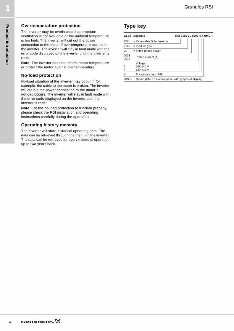
Type key
Code Example RSI 0100 3L 0003 4 X HMGR
RSI = Renewable Solar Inverter
0100 = Product type
3L = Three-phase power
00030072
Rated current [A]
24
Voltage 208-240 V380-415 V
X Enclosure class IP66
HMGR Option (HMGR: Control panel with graphical display)
Ap
pli
ca
tio
ns
Grundfos RSI 2
2. Applications
RSI is designed for continuous as well as intermittent operation. The system is suitable for various water supply systems including irrigation.
RSI can be used in existing systems with submersible pumps or dry-installed pumps, thus providing a very wide range of applications allowing you to leverage renewable energy sources with the ability to back up the system with grid or generator power.
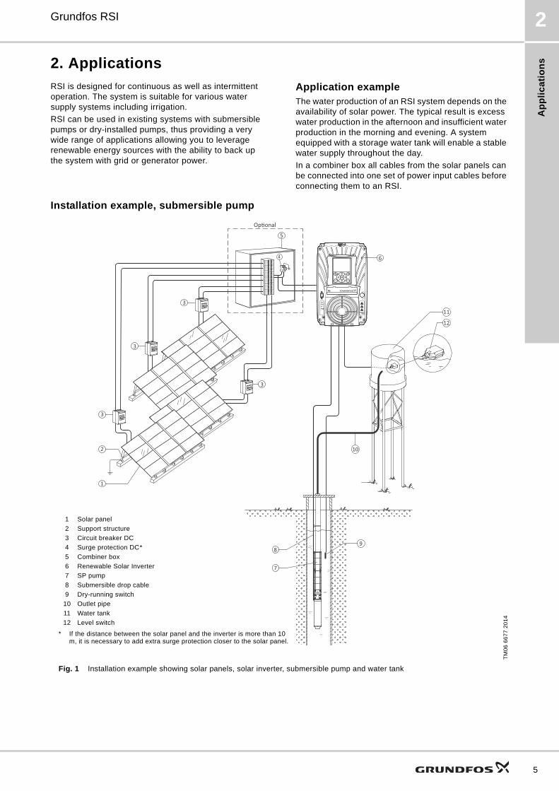
Application exampleThe water production of an RSI system depends on the availability of solar power. The typical result is excess water production in the afternoon and insufficient water production in the morning and evening. A system equipped with a storage water tank will enable a stable water supply throughout the day.
In a combiner box all cables from the solar panels can be connected into one set of power input cables before connecting them to an RSI.
Installation example, submersible pump
Fig. 1 Installation example showing solar panels, solar inverter, submersible pump and water tank
TM
06
66
77
20
14
1
2
8
7
4
10
11
12
9
3
3
3
6
5
3
1 Solar panel
2 Support structure
3 Circuit breaker DC
4 Surge protection DC*
5 Combiner box
6 Renewable Solar Inverter
7 SP pump
8 Submersible drop cable
9 Dry-running switch
10 Outlet pipe
11 Water tank
12 Level switch
* If the distance between the solar panel and the inverter is more than 10 m, it is necessary to add extra surge protection closer to the solar panel.
5
Sy
ste
m c
om
po
ne
nts
6
Grundfos RSI3
3. System components
An RSI system consists of a three-phase Grundfos motor, an RSI solar inverter, and various protection accessories.
The RSI system components include the following components:
• a Grundfos motor
• an RSI
• a circuit breaker, AC (optional)
• a circuit breaker, DC
• a surge protection, DC
• a solar panel
• a dry-running switch
• a level switch (optional)
• a sine wave filter (optional)
• a combiner box.
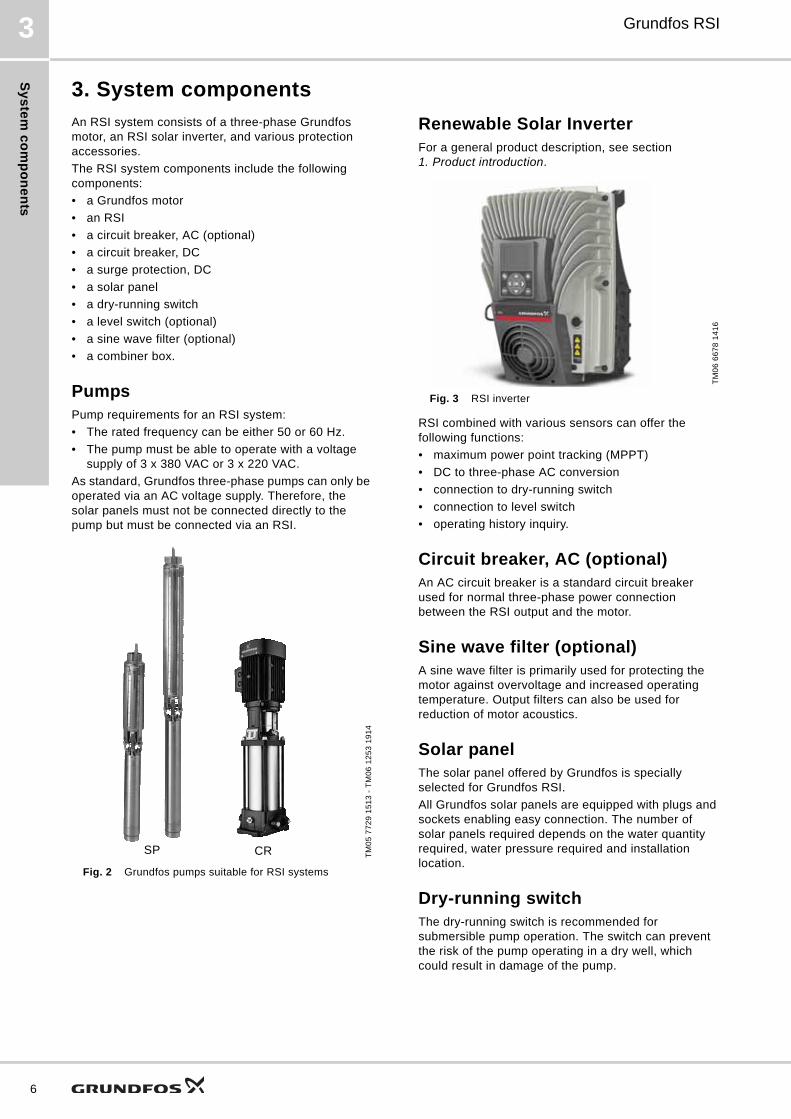
PumpsPump requirements for an RSI system:
• The rated frequency can be either 50 or 60 Hz.
• The pump must be able to operate with a voltage supply of 3 x 380 VAC or 3 x 220 VAC.
As standard, Grundfos three-phase pumps can only be operated via an AC voltage supply. Therefore, the solar panels must not be connected directly to the pump but must be connected via an RSI.
Fig. 2 Grundfos pumps suitable for RSI systems
Renewable Solar InverterFor a general product description, see section 1. Product introduction.
Fig. 3 RSI inverter
RSI combined with various sensors can offer the following functions:
• maximum power point tracking (MPPT)
• DC to three-phase AC conversion
• connection to dry-running switch
• connection to level switch
• operating history inquiry.
Circuit breaker, AC (optional)An AC circuit breaker is a standard circuit breaker used for normal three-phase power connection between the RSI output and the motor.
Sine wave filter (optional)A sine wave filter is primarily used for protecting the motor against overvoltage and increased operating temperature. Output filters can also be used for reduction of motor acoustics.
Solar panelThe solar panel offered by Grundfos is specially selected for Grundfos RSI.
All Grundfos solar panels are equipped with plugs and sockets enabling easy connection. The number of solar panels required depends on the water quantity required, water pressure required and installation location.
Dry-running switchThe dry-running switch is recommended for submersible pump operation. The switch can prevent the risk of the pump operating in a dry well, which could result in damage of the pump.
TM
05
77
29
15
13
- T
M0
6 1
25
3 1
91
4
SP CR
TM
06
66
78
14
16
Sy
ste
m c
om
po
ne
nts
Grundfos RSI 3
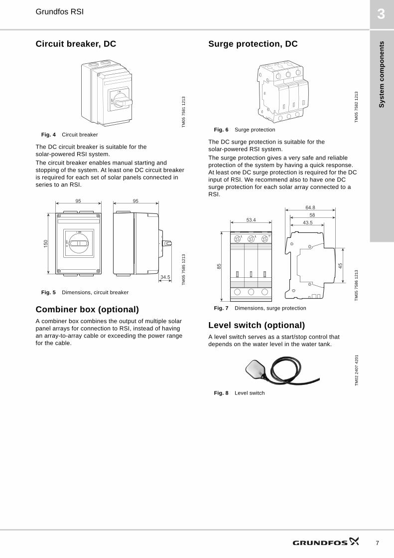
Circuit breaker, DC
Fig. 4 Circuit breaker
The DC circuit breaker is suitable for the solar-powered RSI system.
The circuit breaker enables manual starting and stopping of the system. At least one DC circuit breaker is required for each set of solar panels connected in series to an RSI.
Fig. 5 Dimensions, circuit breaker
Combiner box (optional)A combiner box combines the output of multiple solar panel arrays for connection to RSI, instead of having an array-to-array cable or exceeding the power range for the cable.
Surge protection, DC
Fig. 6 Surge protection
The DC surge protection is suitable for the solar-powered RSI system.
The surge protection gives a very safe and reliable protection of the system by having a quick response. At least one DC surge protection is required for the DC input of RSI. We recommend also to have one DC surge protection for each solar array connected to a RSI.
Fig. 7 Dimensions, surge protection
Level switch (optional)A level switch serves as a start/stop control that depends on the water level in the water tank.
Fig. 8 Level switch
TM
05
75
81
12
13
TM
05
75
85
12
13
I ON
O O
FF
150
95 95
34.5
TM
05
75
82
12
13
TM
05
75
86
12
13
TM
02
24
07
42
01
43.558
64.8
85 45
53.4
LL
7
Te
ch
nic
al d
ata
8
Grundfos RSI4
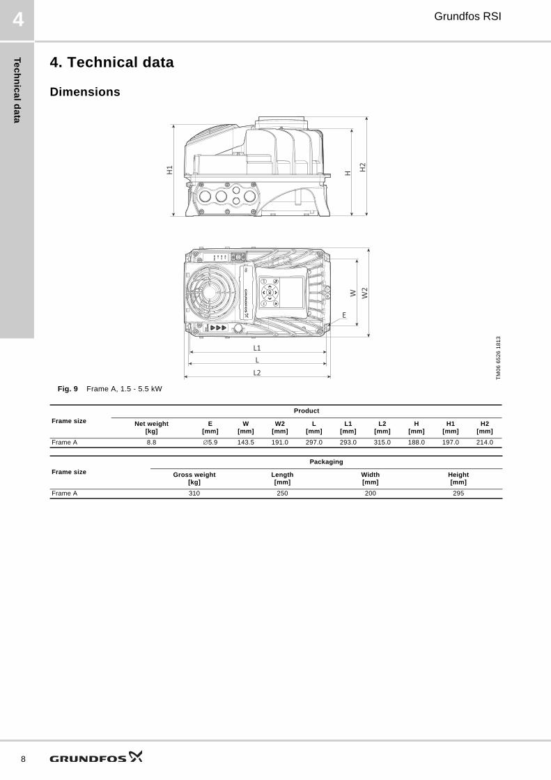
4. Technical data
Dimensions
Fig. 9 Frame A, 1.5 - 5.5 kW
TM
06
65
26
18
13
Frame size
Product
Net weight[kg]
E [mm]
W [mm]
W2[mm]
L[mm]
L1[mm]
L2[mm]
H[mm]
H1[mm]
H2[mm]
Frame A 8.8 ∅5.9 143.5 191.0 297.0 293.0 315.0 188.0 197.0 214.0
E
W W2
L1LL2
H H2H1
Frame size
Packaging
Gross weight[kg]
Length[mm]
Width[mm]
Height[mm]
Frame A 310 250 200 295
Te
ch
nic
al
da
ta
Grundfos RSI 4
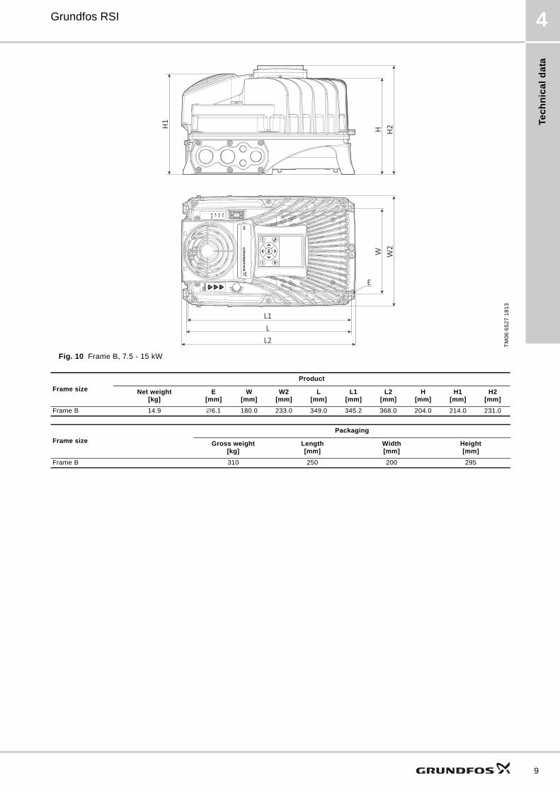
Fig. 10 Frame B, 7.5 - 15 kW
TM
06
65
27
18
13
Frame size
Product
Net weight[kg]
E [mm]
W [mm]
W2[mm]
L[mm]
L1[mm]
L2[mm]
H[mm]
H1[mm]
H2[mm]
Frame B 14.9 ∅6.1 180.0 233.0 349.0 345.2 368.0 204.0 214.0 231.0
E
W W2
H H2
H1
L1LL2
Frame size
Packaging
Gross weight[kg]
Length[mm]
Width[mm]
Height[mm]
Frame B 310 250 200 295
9
Te
ch
nic
al d
ata
10
Grundfos RSI4
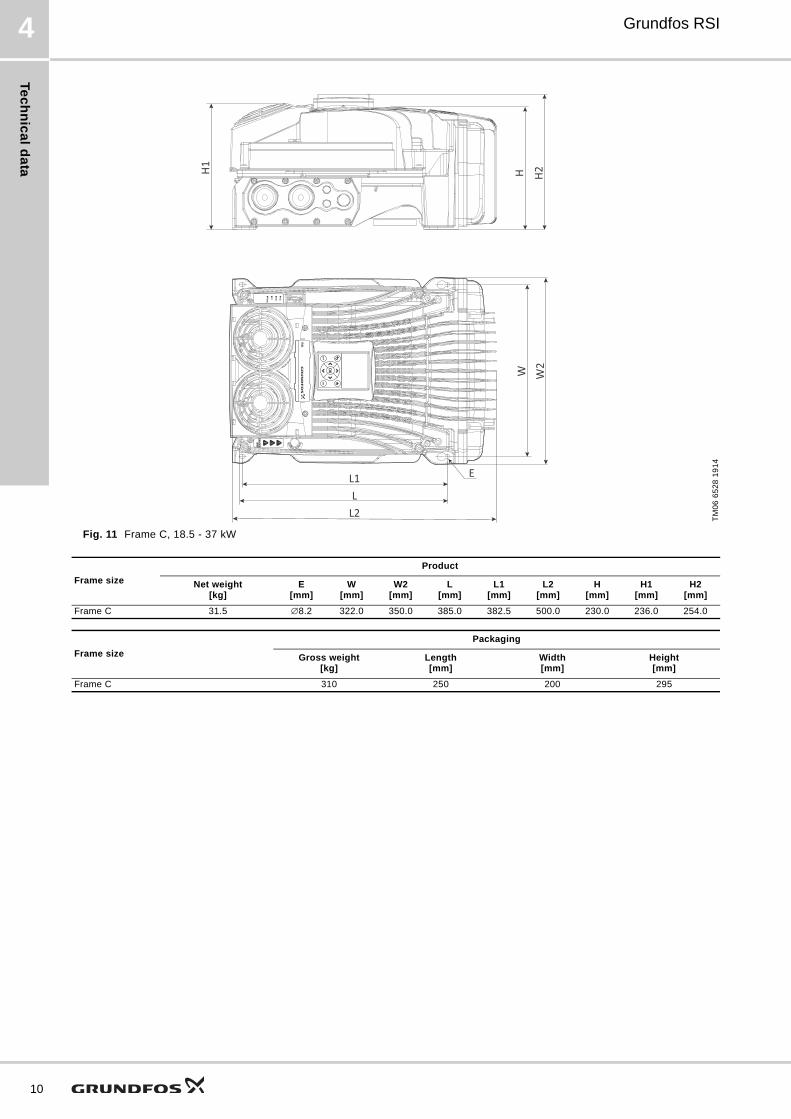
Fig. 11 Frame C, 18.5 - 37 kW
TM
06
65
28
19
14
Frame size
Product
Net weight[kg]
E [mm]
W [mm]
W2[mm]
L[mm]
L1[mm]
L2[mm]
H[mm]
H1[mm]
H2[mm]
Frame C 31.5 ∅8.2 322.0 350.0 385.0 382.5 500.0 230.0 236.0 254.0
E
W W2
H H2H1
L1LL2
Frame size
Packaging
Gross weight[kg]
Length[mm]
Width[mm]
Height[mm]
Frame C 310 250 200 295
Te
ch
nic
al
da
ta
Grundfos RSI 4
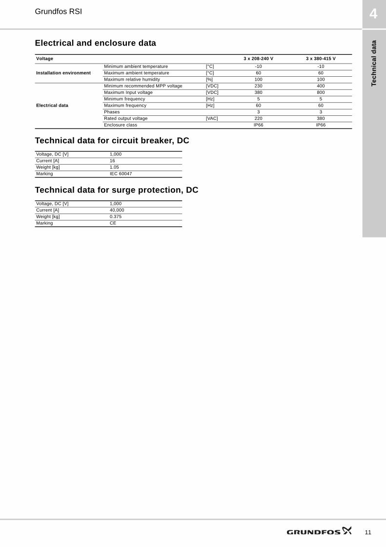
Electrical and enclosure data
Technical data for circuit breaker, DC
Technical data for surge protection, DC
Voltage 3 x 208-240 V 3 x 380-415 V
Installation environment
Minimum ambient temperature [°C] -10 -10
Maximum ambient temperature [°C] 60 60
Maximum relative humidity [%] 100 100
Electrical data
Minimum recommended MPP voltage [VDC] 230 400
Maximum Input voltage [VDC] 380 800
Minimum frequency [Hz] 5 5
Maximum frequency [Hz] 60 60
Phases 3 3
Rated output voltage [VAC] 220 380
Enclosure class IP66 IP66
Voltage, DC [V] 1,000
Current [A] 16
Weight [kg] 1.05
Marking IEC 60047
Voltage, DC [V] 1,000
Current [A] 40,000
Weight [kg] 0.375
Marking CE
11
Pro
du
ct n
um
be
rs
12
Grundfos RSI5
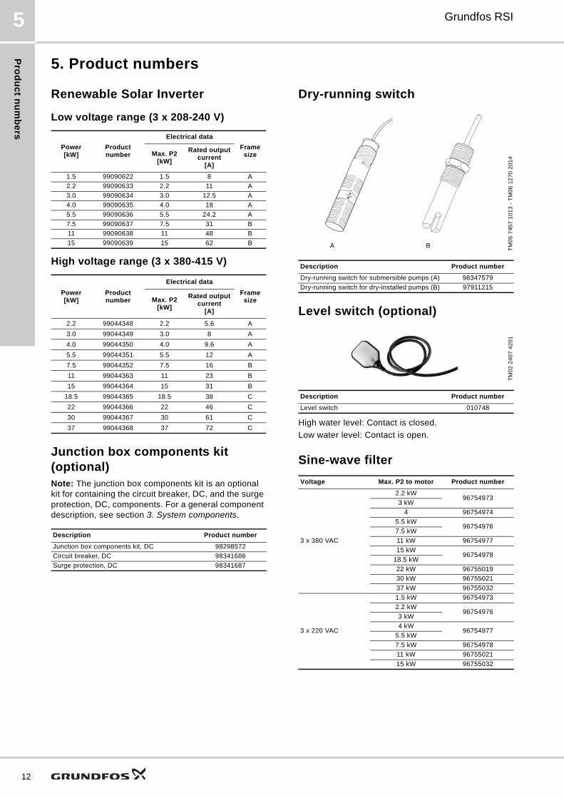
5. Product numbers
Renewable Solar Inverter
Low voltage range (3 x 208-240 V)
High voltage range (3 x 380-415 V)
Junction box components kit (optional)Note: The junction box components kit is an optional kit for containing the circuit breaker, DC, and the surge protection, DC, components. For a general component description, see section 3. System components.
Dry-running switch
Level switch (optional)
High water level: Contact is closed.
Low water level: Contact is open.
Sine-wave filter
Power[kW]
Product number
Electrical data
Frame sizeMax. P2
[kW]
Rated output current
[A]
1.5 99090622 1.5 8 A
2.2 99090633 2.2 11 A
3.0 99090634 3.0 12.5 A
4.0 99090635 4.0 18 A
5.5 99090636 5.5 24.2 A
7.5 99090637 7.5 31 B
11 99090638 11 48 B
15 99090639 15 62 B
Power[kW]
Product number
Electrical data
Frame sizeMax. P2
[kW]
Rated output current
[A]
2.2 99044348 2.2 5.6 A
3.0 99044349 3.0 8 A
4.0 99044350 4.0 9.6 A
5.5 99044351 5.5 12 A
7.5 99044352 7.5 16 B
11 99044363 11 23 B
15 99044364 15 31 B
18.5 99044365 18.5 38 C
22 99044366 22 46 C
30 99044367 30 61 C
37 99044368 37 72 C
Description Product number
Junction box components kit, DC 98298572
Circuit breaker, DC 98341686
Surge protection, DC 98341687
TM
05
74
57
10
13
- T
M0
6 1
27
0 2
01
4
Description Product number
Dry-running switch for submersible pumps (A) 98347579
Dry-running switch for dry-installed pumps (B) 97911215
TM
02
24
07
42
01
Description Product number
Level switch 010748
Voltage Max. P2 to motor Product number
3 x 380 VAC
2.2 kW96754973
3 kW
4 96754974
5.5 kW96754976
7.5 kW
11 kW 96754977
15 kW96754978
18.5 kW
22 kW 96755019
30 kW 96755021
37 kW 96755032
3 x 220 VAC
1.5 kW 96754973
2.2 kW96754976
3 kW
4 kW96754977
5.5 kW
7.5 kW 96754978
11 kW 96755021
15 kW 96755032
A B
Ap
pe
nd
ix
Grundfos RSI 6
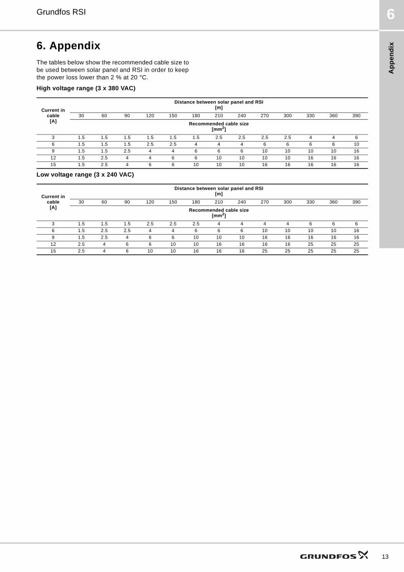
6. Appendix
The tables below show the recommended cable size to be used between solar panel and RSI in order to keep the power loss lower than 2 % at 20 °C.
High voltage range (3 x 380 VAC)
Low voltage range (3 x 240 VAC)
Current in cable
[A]
Distance between solar panel and RSI[m]
30 60 90 120 150 180 210 240 270 300 330 360 390
Recommended cable size [mm2]
3 1.5 1.5 1.5 1.5 1.5 1.5 2.5 2.5 2.5 2.5 4 4 6
6 1.5 1.5 1.5 2.5 2.5 4 4 4 6 6 6 6 10
9 1.5 1.5 2.5 4 4 6 6 6 10 10 10 10 16
12 1.5 2.5 4 4 6 6 10 10 10 10 16 16 16
15 1.5 2.5 4 6 6 10 10 10 16 16 16 16 16
Current in cable
[A]
Distance between solar panel and RSI[m]
30 60 90 120 150 180 210 240 270 300 330 360 390
Recommended cable size[mm2]
3 1.5 1.5 1.5 2.5 2.5 2.5 4 4 4 4 6 6 6
6 1.5 2.5 2.5 4 4 6 6 6 10 10 10 10 16
9 1.5 2.5 4 6 6 10 10 10 16 16 16 16 16
12 2.5 4 6 6 10 10 16 16 16 16 25 25 25
15 2.5 4 6 10 10 16 16 16 25 25 25 25 25
13
Gru
nd
fos
Pro
du
ct C
en
ter
14
Grundfos RSI7
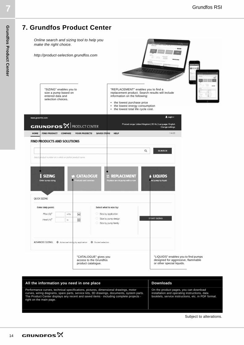
7. Grundfos Product Center
Subject to alterations.
All the information you need in one place Downloads
Performance curves, technical specifications, pictures, dimensional drawings, motor curves, wiring diagrams, spare parts, service kits, 3D drawings, documents, system parts. The Product Center displays any recent and saved items - including complete projects - right on the main page.
On the product pages, you can download installation and operating instructions, data booklets, service instructions, etc. in PDF format.
"SIZING" enables you to size a pump based on entered data and selection choices.
Online search and sizing tool to help you make the right choice.
http://product-selection.grundfos.com
"REPLACEMENT" enables you to find a replacement product. Search results will include information on the following:
• the lowest purchase price• the lowest energy consumption• the lowest total life cycle cost.
"CATALOGUE" gives you access to the Grundfos product catalogue.
"LIQUIDS" enables you to find pumps designed for aggressive, flammable or other special liquids.

15
GRUNDFOS A/S DK-8850 Bjerringbro . DenmarkTelephone: +45 87 50 14 00www.grundfos.com
98462976 0616
ECM: 1187156 Th
e n
am
e G
run
dfo
s, t
he
Gru
nd
fos
log
o,
an
d b
e t
hin
k i
nn
ov
ate
are
re
gis
tere
d t
rad
em
ark
s o
wn
ed
by
Gru
nd
fos
Ho
ldin
g A
/S o
r G
run
dfo
s A
/S,
De
nm
ark
. A
ll ri
gh
ts r
ese
rve
d w
orl
dw
ide
.©
Co
pyr
igh
t G
run
dfo
s H
old
ing
A/S